1
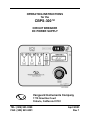
OPERATING INSTRUCTIONS for the CBPS-300™ CIRCUIT BREAKER DC POWER SUPPLY Vanguard Instruments Company 1710 Grevillea Court Ontario, California 91761 TEL: (909) 923-9390 FAX: (909) 923-9391 April 2003 Rev 1 CBPS-300 OPERATING INSTRUCTIONS SAFETY WARNINGS AND CAUTIONS Only trained operators shall use this device. All circuit breakers under test shall be off line and fully isolated. Do Not Service or Test Alone Do not perform test procedures or service unless another person is also present who is capable of rendering aid and resuscitation. Do Not Modify Test Equipment Due to the added risk of introducing additional or unknown hazards, do not install substitute parts or perform any unauthorized modification to any CBPS-300 test unit. To ensure that all designed safety features are maintained, it is recommended that repairs be performed only by Vanguard Instruments Company’s factory personnel or by an authorized repair service center. Unauthorized modifications can cause serious safety hazards and will nullify the manufacturer's warranty. Follow Exact Operating Procedures Any deviation from the procedures described in the operator’s manual may create one or more safety hazards, damage the CBPS-300 and the test transformer, or cause errors in the test results. Vanguard Instruments Company, Incorporated assumes no liability for unsafe or improper use of the CBPS-300. 1 CBPS-300 OPERATING INSTRUCTIONS Table of Contents 1.0 INTRODUCTION...................................................................................................... 4 1.1 GENERAL DESCRIPTION ........................................................................................... 4 1.2 FUNCTIONAL DESCRIPTION ...................................................................................... 4 1.3 FURNISHED ACCESSORIES ....................................................................................... 4 2.0 CBPS-300 SPECIFICATIONS ................................................................................. 5 3.0 CONTROLS and INDICATORS ............................................................................... 6 4.0 PRETEST SETUP.................................................................................................... 9 4.1 OPERATING VOLTAGES ............................................................................................ 9 5.0 OPERATING PROCEDURES................................................................................ 10 5.1 CBPS-300 CABLE CONNECTION ............................................................................ 10 5.2 GENERAL PROCEDURES ........................................................................................ 11 5.3 TEST OPEN COIL PROCEDURE ............................................................................. 11 5.4 TEST CLOSE COIL PROCEDURE ........................................................................... 11 5.5 ENERGIZE SPRING CHARGING MOTOR PROCEDURE ................................................ 12 5.6 REMOTE CONTROL MODE ...................................................................................... 12 2 CBPS-300 OPERATING INSTRUCTIONS List of Tables Table 1.0 CBPS-300 SPECIFICATIONS....................................................................... 5 Table 2.0 Functional Descriptions of the CBPS-300 Controls and Indicators................ 7 Table 2.0 Functional Descriptions of CBPS-300 Controls and Indicators Cont. ............ 8 List of Figures Figure 1.0 CBPS-300 Controls and Indicators................................................................ 6 Figure 2.0 90 to 130Vac Switch Setting.......................................................................... 9 Figure 3.0 200 to 240 Vac Switch setting ....................................................................... 9 Figure 4.0 Typical CBPS-300 Connection Diagram...................................................... 10 3 CBPS-300 OPERATING INSTRUCTIONS 1.0 INTRODUCTION 1.1 General Description Vanguard Instruments Company produces the CBPS-300 as a microprocessorcontrolled circuit breaker DC power supply. This device was designed to replace the substation batteries during circuit breaker testing. The CBPS provides a ripple free, DC power source to operate utility circuit breakers for contact-timing and other breaker operations. The CBPS-300 allows the user to operate the OPEN and CLOSE coils of a circuit breaker during tests under different selectable operating conditions such as full voltage or minimum voltage operations. External trigger input allows the CBPS-300 to be used with the Vanguard Instruments circuit breaker timers. A separate DC supply is also available to drive the breaker mechanism charging motor. All CBPS-300 supply outputs are over current and short circuit protected. This feature protects the CBPS-300 powersupplies and eliminates the use of conventional fuses or circuit breaker protection circuitry. The CBPS-300 test voltage is selectable from 24Vdc to 250Vdc. The voltage control knob on the CBPS-300 front panel allows the operators to select test voltages. Coil or charging motor voltage reading is displayed on a 2 line by 16-character back lit LCD screen. Push button switches marked OPEN, CLOSE and MOTOR are used to operate the breaker’s respected coils and charging motor voltage variation under-load; making it an ideal device for testing circuit breaker coils under different operating voltages. A built-in initiate circuit allows the user to OPEN or CLOSE breakers from the CBPS300 control panel. The CBPS-300 will energize the breaker trip or close coil for one-second duration. This initiate circuit is over current and short circuit protected. Reset key on the front panel allows the user to clear the fault condition. An unfiltered DC supply is also available to drive the breaker mechanism charging motor. A voltage control knob allows the user to set coil or motor test DC voltage. DC voltage output is shown on the 2 lines by 16 characters back-lighted LCD. 1.3 Furnished Accessories The CBPS-300 is shipped with six 10-foot test cables with “quick disconnect” type test plugs on the unit end, and alligator clips at the test load end. The following cables shall also be included with the CBPS-300: One power cord, One ground cable and a cablecarrying bag. 1.2 Functional Description The CBPS-300 is a variable voltage DC power supply designed specifically to perform maintenance test on circuit breakers. The CBPS-300 DC voltage is selectable for 24Vdc to 250Vdc. Its ripple free DC output voltage is regulated up to 2% 4 CBPS-300 OPERATING INSTRUCTIONS 2.0 CBPS-300 SPECIFICATIONS Table 1.0 CBPS-300 SPECIFICATIONS TYPE Special-purpose test equipment, Variable DC Power Supply SIZE (inches) 16.8” wide by 12.6” high by 12”deep (42.6cm x 32 cm x 27cm) WEIGHT 60 pounds (27 Kg) INPUT POWER 120 Vac or 240Vac selectable, 50/60Hz DISPLAY 2 line by 16 character back-lighted LCD VOLT METER DISPLAY 0-300VDC, ±1 V OUTPUT VOLTAGE 12 to 250 Vdc COIL DC POWER SUPPLY DC OUTPUT 24 Vdc 48 Vdc 120 Vdc 250 Vdc CURRENT 10A 10A 6A 3A REGULATION <6% <3% <2% <2% CHARGING MOTOR DC POWER SUPPLY NO LOAD VLTG 48 Vdc 48 Vdc 120 Vdc 120 Vdc 240 Vdc 240 Vdc LOAD CURRENT 12A 18A 12A 18A 6A 9A LOAD INTERVAL 60 S 20 S 60 S 20 S 60 S 20 S FULL LOAD VLTG 40 Vdc 30 Vdc 90 Vdc 70 Vdc 200 Vdc 185 Vdc OUTPUT PROTECTION All DC outputs are over-current protected ENVIRONMENT Operating: -10°C to 55°C; Storage: -40°C to 65°C WARRANTY One-year parts & labor (post warranty service is available) NOTE: THE ABOVE SPECIFICATIONS ARE VALID AT NOMINAL OPERATING VOLTAGE AND AT A TEMPERATURE OF 25°C (77°F) CBPS-300 SPECIFICATIONS MAY BE UPGRADED AND CHANGED WITHOUT PRIOR NOTICE. 5 CBPS-300 OPERATING INSTRUCTIONS 3.0 CONTROLS AND INDICATORS CBPS-300 controls and indicators are shown in Figure 1.0. The leader line with an index number points to each control or indicator, which is then cross-referenced to a functional description in Table 2.0. The table describes the function of each item on the control-panel. The purpose of the controls and indicators may seem obvious, Figure 1.0 but users should become familiar with them before using the CBPS-300. Accidental misuse of the controls may damage the CBPS-300. Users should also be familiar with the Safety Warnings and Cautions found on the front page of this operator’s manual. CBPS-300 Controls and Indicators 6 CBPS-300 OPERATING INSTRUCTIONS Table 2.0 Fig. 1 Index Functional Descriptions of the CBPS-300 Controls and Indicators Panel Markings Functional Descriptions 1 NONE OPEN coil voltage positive terminal. Female, Red connector jacks used for connecting voltage test leads. 2 NONE 3 NONE 4 EXT TRIGGER 5 NONE 6 NONE MOTOR voltage positive terminal. Female, Red connector jacks used for connecting voltage test leads. 7 NONE MOTOR coil voltage negative terminal. Female, Black connector jacks used for connecting voltage test leads. 8 FAULT RESET Fault LED. Led is lit when over current is detected. RESET switch. Reset fault condition and ready CBPS-300 for next operation. 9 NONE 10 120/240 Vac, 8A, 50- 60 Hz 11 NONE OPEN coil voltage negative terminal. Female, Black connector jacks used for connecting voltage test leads. CLOSE coil voltage positive terminal. Female, Red connector jacks used for connecting voltage test leads. External trigger input for remote control. This input is to be used with the Vanguard Instruments Company circuit breaker timers. Female, 4 pin connector. CLOSE coil voltage negative terminal. Female, Black connector jacks used for connecting voltage test leads. LCD; 2-line by 16-character; back-lighted; Displays coil/motor voltages. Input power connector with third-wire safety ground and 10A built-in circuit breaker Safety Ground. A 5/16 threaded stud with handturned wing nut. This must be connected to the station ground before connecting any CBPS-300 test leads to the transformer. 7 CBPS-300 OPERATING INSTRUCTIONS Table 2.0 Functional Descriptions of CBPS-300 Controls and Indicators Cont. Fig. 1 Index Panel Markings 12 VOLTAGE CONTROL 13 COIL/MOTOR 14 MOTOR Functional Descriptions Voltage control knob. Coil or Motor voltage display selection. 15 16 Motor voltage initiate switch. Depress switch to energize motor. CLOSE Close coil initiate switch. Depress switch to energize close coil. The CBPS-300 will energized the close coil for 1 second period. OPEN Trip coil initiate switch. Depress switch to energize close coil. The CBPS-300 will energized the close coil for 1 second period. 8 CBPS-300 OPERATING INSTRUCTIONS 4.0 PRETEST SETUP 4.1 Operating Voltages The operating voltages for the CBPS-300 are selectable between 90-130 Volts AC, 50/60 Hertz or 200-240 Volts AC, 50/60 Hertz. Voltage selection is set by the 120/240 selector switch as how in Figures 2.0 and Figure 3.0. Figure 2.0 90 to 130Vac Switch Setting Figure 3.0 200 to 240 Vac Switch setting 9 CBPS-300 OPERATING INSTRUCTIONS 5.0 OPERATING PROCEDURES Before using the CBPS-300, operators should familiarize themselves with the CBPS-300 controls and indicators. Figure 4.0 5.1 CBPS-300 Cable connection A typical connection diagram of the CBPS300 is shown in Figure 3.0. Typical CBPS-300 Connection Diagram . 10 CBPS-300 OPERATING INSTRUCTIONS 5.2 General Procedures a. Ground the CBPS-300 to the substation ground. (Item 11 in Figure 1.0.) 300. Failure to follow this procedure may damage the CBPS-300. 5.3 Test OPEN Coil Procedure The following procedures will allow the operator to initiate an Open operation. b. Disconnect Circuit breaker control circuitry from the substation battery. a. Make sure the CBPS-300 display voltage is selected to display coil voltage. Press Coil/Motor switch to display coil voltage. WARNING Never connect the CBPS-300 control signals to substation battery or live circuit. Failure to follow this procedure will damage the CBPS-300. b. Turn the voltage control knob to select the desired test voltage. Observe test voltage displayed on the LCD as shown below: c. Plug the CBPS-300 power cable into a power outlet. COIL VLTG: 120.0 V WARNING Always return the voltage control knob to the zero position before connecting or disconnecting the CBPS-300 test leads. NOTE Allow 3 seconds after turning voltage control knob for the voltage display to be stable. d. Connect the CBPS-300 positive and negative cable clips to the appropriate terminals of the trip coil. c. Press the control OPEN switch to energize OPEN coil. e. Connect the CBPS-300 positive and negative cable clips to the appropriate terminals of the close coil. d. Observe OPEN coil was energized and circuit breaker was opened. f. Connect the CBPS-300 positive and negative cable clips to the appropriate terminals of the circuit breaker motor. e. If an over-current condition was detected, the FAULT LED will be lit. f. Check the OPEN coil connection. Press RESET switch and go to step c to open circuit breaker. g. Turn voltage control knob to zero. Turn on the CBPS-300 power. Observe that after configuration data is displayed briefly, the coil voltage is displayed on LCD as shown below: g. To end test, turn the voltage control knob to zero position before turning off CBPS300. COIL VLTG: 0.0V 5.4 Test CLOSE Coil Procedure The following procedures will allow the operator to initiate a CLOSE operation. WARNING Always turn the CBPS-300 voltage control knob to zero before turning on the CBPS- a. Make sure the CBPS-300 display voltage is selected to display coil voltage. Press Coil/Motor switch to display coil voltage. 11 CBPS-300 OPERATING INSTRUCTIONS b. Turn the voltage control knob to select the desired test voltage. Observe test voltage displayed on the LCD as shown below: b. Turn the voltage control knob to select the desired test voltage. Observe test voltage displayed on the LCD as shown below: MOTOR VLTG: 120.0 V COIL VLTG: 120.0 V NOTE Allow 3 seconds after setting voltage control knob for the voltage display to be stable. NOTE Allow 3 seconds after turning voltage control knob for the voltage display to be stable. c. Hold the MOTOR switch to energize circuit breaker charging motor. c. Press the control CLOSE switch to energize CLOSE coil. d. Observe circuit breaker charging motor is energizing. d. Observe CLOSE coil was energized and circuit breaker was closed. e. Release switch after spring was charged. e. If an over-current condition was detected, the FAULT LED will be lit. f. If an over-current condition was detected, the FAULT LED will be lit. f. Check the CLOSE coil connection. Press RESET switch and go to step c to close circuit breaker. g. Check motor lead connection. Press RESET switch and go to step c to energize charging motor. g. To end test, turn the voltage control knob to zero position before turning off CBPS300. h. To end test, turn the voltage control knob to zero position before turning off CBPS300. WARNING Always return the voltage control knob to the zero position before connecting or disconnecting the CBPS-300 test leads. WARNING Always return the voltage control knob to the zero position before connecting or disconnecting the CBPS-300 test leads. 5.5 Energize Spring Charging Motor Procedure The following procedures will allow the operator to energize circuit breaker charging motor. 5.6 Remote control Mode The CBPS-300 can be control by the Vanguard Instrument circuit breaker timers (CT-6500, CT-7000, CT-7500). The following procedures allow the user to operate the CBPS-300 with the Vanguard Instrument timers. a. Make sure the CBPS-300 display voltage is selected to display coil voltage. Press Coil/Motor switch to display motor voltage. a. Connect the initiate cable from the CTXXX timer to the CBPS-300. b. Turn the voltage control knob to zero. 12 CBPS-300 OPERATING INSTRUCTIONS c. Turn on the CBPS-300. d. Turn the voltage control knob to select the desired test voltage. Observe test voltage displayed on the LCD as shown below: COIL VLTG: 120.0 V NOTE Allow 3 seconds after turning voltage control knob for the voltage display to be stable. e. Initiate Open or Close command from the circuit breaker timer. f. Observe circuit breaker operated. g. To end test, turn the voltage control knob to zero position before turning off CBPS300. WARNING Always return the voltage control knob to the zero position before connecting or disconnecting the CBPS-300 test leads. 13 CBPS-300 OPERATING INSTRUCTIONS 1710 Grevillea Court, Ontario, CA 91761, USA Phone: 909-923-9390 Fax: 909-923-9391 Website: http//www.vanguard-instruments.com CBPS-300 04/01/03: 14