1
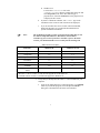
USING YOUR NI-DAQ SOFTWARE
WITH YOUR VXI-DAQ MODULE
Introduction
These notes describe your options when using NI-DAQ for PC
Compatibles version 5.1 or later with your VXI-data acquisition
(VXI-DAQ) module.
Note:
The information in these release notes applies only to configurations
using National Instruments VXIbus controllers.
NI-DAQ for PC Compatibles version 5.1 supports the following
VXI-DAQ products:
•
VXI-DIO-128
•
VXI-MIO-64XE-10
•
VXI-MIO-64E-1
•
VXI-AO-48XDC
•
VXI-SC-1000
•
VXI-SC-1102
•
VXI-SC-1150
on the following operating systems:
•
Windows 95
•
Windows NT 4.0
ComponentWorks ™, CVI ™, LabVIEW ™, MITE ™, NI-DAQ ™, NI-VISA ™, NI-VXI ™, VirtualBench ™, and VXIpc ™ are trademarks of National Instruments
Corporation. Product and company names are trademarks or trade names of their respective companies.
321519B-01
© Copyright 1996, 1997 National Instruments Corp. All rights reserved.
October 1997
Software Installation
A typical installation includes these National Instruments driver software
products:
•
NI-VXI
•
NI-VISA
•
NI-DAQ for PC Compatibles
•
VXIplug&play Instrument Driver and Soft Front Panels
and one or more of these National Instruments application software
packages and documentation:
Note:
•
LabVIEW
•
LabWindows /CVI
•
ComponentWorks
•
VirtualBench
™
If you are using LabVIEW and are new to VXI and data acquisition,
refer to the LabVIEW DAQ Basics Manual.
Perform the following steps to install your software:
1.
Verify that you have the correct version of NI-VXI installed on your
computer. The necessary version number will vary with your
configuration; Table 1 lists the possible controller and operating
system combinations and the oldest version of NI-VXI you can use
to create VXI-DAQ applications.
To determine the version of NI-VXI you have installed on your
computer, perform the following steps:
a.
If you are using a VXIpc-800/700 Series embedded controller,
PCI-MXI-2 controller, or AT-MXI-2 controller, perform the
following steps:
♦
Windows 95
Look for the NIVXIINT.DLL file in the \WINDOWS\SYSTEM
directory. Right-click on the file and select Properties in
the menu. This will bring up a properties box. Select the
Version tab on the properties box to display the file version.
2
♦
Note:
Windows NT
Look for the NIVXIINT.DLL file in the
\WINDOWS\SYSTEM32 directory. Right-click on the file and
select Properties in the menu. This will bring up a
properties box. Select the Version tab on the properties box
to display the file version.
b.
If you have a different controller, run VICTEXT. Type in the
command version. Your NI-VXI version will be displayed.
c.
If you do NOT have the correct version of NI-VXI installed,
install it at this time. See your NI-VXI documentation for
specific installation instructions.
The NI-DAQ CD includes versions of NI-VXI and NI-VISA that you can
use with the VXIpc-800/700 Series, PCI-MXI-2, and AT-MXI-2
controllers. If your version of NI-VXI or NI-VISA is prior to the listed
versions, you should install the correct version from the NI-DAQ CD.
Table 1. NI-VXI Version Options
Controller
Windows 95
Windows NT 4.0
VXIpc-860
1.5.1
1.5.1
VXIpc-850
1.5
1.5
VXIpc-700 Series
1.5
1.5
PCI-MXI-2
1.5
1.5
AT-MXI-2
1.0*
N/A (not supported)
AT-MXI-1
3.3†
1.1
VXIpc-486, Model 500
Series
1.4
1.1
* Windows 3.1 driver version 1.0 with NI-VXI upgrade kit for Windows 95
† AT-MXI-1 driver revision 3.3 with NI-VXI upgrade to Windows 95
2.
Verify that you already have NI-VISA 1.1 or later installed on your
computer:
a.
Look for the VISA Interactive Control program in your VXIpnp
folder. If you find the program, run it and open the About...
dialog box to determine the NI-VISA version number.
3
If you do not find the program, perform the following steps:
♦
Windows 95
Look in the \WINDOWS\SYSTEM\ directory for the
VISA32.DLL file. Right-click on the file and select
Properties in the menu. This will bring up a properties box.
Select the Version tab on the properties box to display the
file version.
♦
Windows NT 4.x
Look in the \WINNT\SYSTEM32\ directory for the
VISA32.DLL file. Right-click on the file and select
properties in the menu. This will bring up a properties box.
Select the Version tab on the properties box to display the
file version.
b.
If you do not have NI-VISA 1.1 or later installed, install it at this
time. Refer to your NI-VISA documentation for specific
instructions.
3.
Install your application software using the appropriate
documentation.
4.
Install NI-DAQ version 5.1 or later on your computer, if it is not
already installed. Use the NI-DAQ CD and release notes that were
included with your VXI-DAQ hardware for NI-DAQ software and
documentation installation instructions.
If NI-DAQ is already installed, run the NI-DAQ Configuration
Utility and check the title bar for the version number. If you have a
version earlier than 5.1, replace it with version 5.1 or later. See your
NI-DAQ release notes for installation instructions.
5.
If you plan to use the VXIplug&play Instrument Driver, install it
using the instructions in the Setup Utility on the diskettes that were
included with your VXI-DAQ hardware.
Your software installation is now complete.
4
Configuration
Configuring Your VXIbus Controller
After you install all your software, run the following configuration
programs to configure your VXIbus system with NI-DAQ:
•
Note:
Note:
Run the Resource Manager, RESMAN, to initialize the VXIbus
modules in your chassis. RESMAN is not an interactive utility. RESMAN
assigns resources to the VXIbus modules in your chassis.
You must run RESMAN every time you reset your VXIbus controller or
VXIbus chassis.
•
Run VXIEDIT or Test & Measurement Explorer to configure your
VXIbus controller. Read the section of this note that is appropriate
for your VXIbus controller to configure your controller to use
VXI-DAQ products.
•
Run the NI-DAQ Configuration Utility to configure your VXI-DAQ
modules. More detailed information is in the Configuring Your
VXI-DAQ Module with NI-DAQ section later in these release notes.
You only need to run VXIEDIT or Test & Measurement Explorer when
you configure your system for the first time or when you add or remove
memory on your controller. You only need to run the NI-DAQ
Configuration Utility when you add or remove VXI-DAQ modules or
when you add or remove memory on your VXI-DAQ modules.
Configuring VXIpc-800/700 Series Embedded
Controllers
♦
Configuration using NI-VXI 1.5 and VXIEDIT
1.
Launch VXIEDIT.
2.
Choose the VXIpc Configuration Editor.
3.
Select Load Configuration From File.
4.
If you have a VXIpc-860 embedded controller, find
\NIVXI\TBL\VDAQ860.CFG and select it. If you have a VXIpc-850
embedded controller, find \NIVXI\TBL\VDAQ850.CFG and select it.
If you have a VXIpc-740 embedded controller, find
\NIVXI\TBL\VDAQ740.CFG and select it.
5
5.
Click on Load.
6.
You should see a message that your Configuration Restored
Successfully.
7.
Select Update Current Configuration. After updating the
EEPROM, return to the main menu.
8.
If you are using VXI-MXI-2 extenders in your system, select the
VXI/VME-MXI-2 Configuration Editor.
9.
For each VXI-MXI-2 in your system, select the Enable Interlocked
Mode field.
10. Reset your VXI chassis and rerun RESMAN.
Note:
After you have configured your controller, if you later add or remove
memory on your controller, you must run VXIEDIT. Choose the Logical
Address Configuration Editor. In the VXI Shared RAM Size control,
select Share All of System Memory and click on OK. You must actually
select the control even if its setting is already Share All of System
Memory. Only by activating the control is the new memory size
calculated. Then perform step 7.
♦
Configuration using NI-VXI 2.0 and Test & Measurement Explorer
1.
Launch Test & Measurement Explorer.
2.
In the System View window, right-click on the VXIpc controller
icon.
3.
Select Hardware Configuration from the pop-up menu.
4.
Under the General tab, select VXI-DAQ Configuration from the
Common Configurations menu.
5.
Click on OK.
6.
The utility will ask you to reboot. Click OK.
7.
If you are using VXI-MXI-2 extenders in your system, right-click on
the first extender shown in the System View window.
8.
Under the General tab, select VXI-DAQ Configuration from the
Common Configurations menu.
9.
Repeat Step 8 for each VXI-MXI-2 extender in your system.
10. Reset your VXI chassis and run RESMAN.
6
Configuring PCI-MXI-2 Controllers
♦
Using NI-VXI 1.5 and VXIEDIT
1.
Launch VXIEDIT.
2.
Choose the PCI-MXI-2 Configuration Editor.
3.
Select Load Configuration From File.
4.
Select \NIVXI\TBL\VXIDAQ.CFG.
5.
Click on Load.
6.
You should see a message that your Configuration Restored
Successfully.
7.
Select Update Current Configuration. After updating the
EEPROM, return to the main menu.
8.
Select the VXI-MXI-2 Configuration Editor for each VXI-MXI-2
in your system by selecting a particular VXI-MXI-2 and clicking on
OK.
9.
Set the Interlocked field to Enable and click on OK. Repeat this
step for each VXI-MXI-2 in your system.
10. Quit VXIEDIT and restart your computer. Power cycle your VXIbus
chassis, then run RESMAN.
Note:
After you have configured your controller, if you later add or remove
memory on your controller, you must run VXIEDIT. Choose the Logical
Address Configuration Editor. In the VXI Shared RAM Size control,
select Share All of System Memory and click on OK. You must actually
select the control even if its setting is already Share All of System
Memory. Only by activating the control is the new memory size
calculated. Then perform step 7.
7
♦
Using NI-VXI 2.0 and Test & Measurement Explorer
1.
Launch Test & Measurement Explorer.
2.
In the System View window, right click on the PCI-MXI-2
controller.
3.
Select Hardware Configuration from the pop-up menu.
4.
Under the General tab, select VXI-DAQ Configuration from the
Common Configurations menu.
5.
Click on OK.
6.
The utility will ask you to reboot. Click OK.
7.
Right-click on the first VXI-MXI-2 extender shown in the System
View window.
8.
Under the General tab, select VXI-DAQ Configuration from the
Common Configurations menu.
9.
Repeat Step 8 for each VXI-MXI-2 extender in your system.
10. Reset your VXI chassis and run RESMAN.
Configuring VXIpc-486 Model 500 Series
Embedded Controllers
No additional configuration steps are necessary for these controllers.
Configuring AT-MXI-2 and AT-MXI-1 Controllers
No additional configuration steps are necessary for these controllers.
Configuring the GPIB-VXI/C Controller
No additional configuration steps are necessary for this controller.
Configuring Your VXI-DAQ Module with NI-DAQ
The NI-DAQ Configuration Utility identifies your VXI-DAQ module and
configures its various operating settings. When using a VXIpc-740,
VXIpc-850, VXIpc-860, or PCI-MXI-2, the NI-DAQ Configuration
Utility automatically detects the VXI-DAQ modules installed in your
system. For the configuration utility to automatically detect modules, you
must have the modules installed in your VXIbus chassis, and you must
have run the Resource Manager, RESMAN, before starting the NI-DAQ
configuration utility.
8
To configure your new VXI-DAQ device for use by NI-DAQ, perform
the following steps:
1.
Run the NI-DAQ Configuration Utility.
2.
The utility should now prompt you to configure a new device in your
computer. Select a device number from the list of device numbers
provided, and click OK.
Note:
If your VXI-DAQ device is not automatically detected, see the
information on manually adding a device later in this section.
Note:
The device number is NOT the same as the VXIbus logical address for the
module.
3.
From the list of devices, select the number for the device you
assigned in step 2. Click the Configure button.
4.
If your device was automatically detected, the Logical Address field
and the VXIbus Address Space are already filled in. If you
manually added a device to your system, perform the following
steps:
a.
b.
Note:
Using the Logical Address control, assign the module its logical
address. This number MUST match the module DIP switch
setting.
•
You cannot use this control to change the module logical
address; you can use it only to associate an NI-DAQ device
number to a logical address.
•
If you do not know the logical address for your module,
RESMAN lists logical addresses as part of its output.
Using the VXIbus Address Space control, assign the module a
VXIbus address space. You can get the current address space as
part of the RESMAN output. You can use this control to change
the A24/A32 address space.
You should select the A32 address space for your VXI-MIO modules. If
you are using the GPIB-VXI/C, select the A24 address space.
5.
Select the VXI Interrupt Request field to assign a VXIbus interrupt
to your MIO module. You can choose any line for this setting.
6.
Use the Apply button to verify your settings. If one or more of your
settings is incorrect and the message Failed to set the resource is
displayed, check your VXI-DAQ device settings.
7.
Test your configuration by clicking the Test button.
9
8.
If you get the message The device did not pass the test, check your
VXI-DAQ device settings.
9.
When finished testing your device, close the panel by clicking on
OK.
10. Before exiting the NI-DAQ Configuration Utility, save the
configuration by selecting the File»Save menu option.
Your VXI-DAQ configuration is complete.
If your VXI-DAQ device was not automatically detected, you can
manually add the device to your configuration. To add a device, perform
the following steps:
♦
♦
Windows 95
1.
Open the Control Panel folder and click on the Add New
Hardware icon.
2.
When prompted with Do you want Windows to search for your
new hardware?, click on No.
3.
If there is a Data Acquisition Devices heading, click on this.
Otherwise, select Other Devices and choose National Instruments
in the Manufacturer setting.
4.
Select the VXI-DAQ module you have installed from the available
choices.
5.
When prompted, click on Finished.
6.
Run the NI-DAQ Configuration Utility and perform the steps for
configuring a new VXI-DAQ device as described in this note.
Windows NT
1.
Run the NI-DAQ Configuration Utility.
2.
Click on the Add button and select the appropriate VXI-DAQ device
from the displayed list.
Follow the steps for configuring a new VXI-DAQ device as described in
this note.
10
Configuring Your VXI-SC Submodule
You must run RESMAN before starting the NI-DAQ Configuration Utility.
Write down the VXI logical address assigned to each VXI-SC
submodule, because the NI-DAQ Configuration Utility cannot
automatically detect VXI-SC submodules. All VXI-SC submodules must
be adjacent and to the right of a VXI-MIO device. For a VXI chassis
oriented in the upright position (controller on the left), the VXI-SC
submodule slots are numbered sequentially, first from top to bottom, then
from left to right.
To configure your new VXI-SC submodule for use by NI-DAQ, perform
the following steps after configuring your VXI-MIO devices:
1.
Run the NI-DAQ Configuration Utility.
2.
Click on the SCXI Devices tab.
3.
On the Chassis panel, click on the Add button and select VXI-SC.
4.
Assign the chassis a Chassis ID and Chassis address. This does NOT
have to match the VXI logical address.
5.
On the Modules panel, click on the Add button and select any
VXI-SC submodules you have installed.
6.
A configuration dialog box will appear. Assign to the submodule the
VXI logical address that you obtained from RESMAN.
7.
There may be other configurable options, such as Connected to,
Operating Mode, and selections for gains and accessories. Select
these as you would for a conventional SCXI module in an external
chassis.
8.
Use the Apply button to verify your settings, then close the panel by
clicking on the OK button.
9.
Test your configuration by using the Test button. If you get the
message, Failed to find VXI-SC-xxxx, check the settings of your
VXI-SC submodule.
10. Before exiting the NI-DAQ Configuration Utility, save the
configuration by selecting the File»Save menu option.
11
Programming Your VXI-DAQ Module
This section provides an overview of the functions available for
programming your VXI-DAQ modules. Additional information is
available in the NI-DAQ Function Reference Manual for PC
Compatibles.
VXI-MIO Series Modules
The VXI-MIO-64XE-10 is functionally equivalent to the
AT-MIO-16XE-10. Any VI or function valid for the AT-MIO-16XE-10
is also valid for the VXI-MIO-64XE-10. The same relationship exists
between the VXI-MIO-64E-1 and the AT-MIO-16E-1. The channel
numbering scheme for both VXI-MIO Series modules is identical to that
of the AT-MIO-64E-3. The few differences that do exist, such as onboard
memory, are discussed in the Common Questions section of this
document.
VXI-DIO-128 Module
The VXI-DIO-128 currently has no functionally equivalent DAQ
hardware. The following sections list the LabWindows/CVI functions
and LabVIEW VIs you will use to program your VXI-DIO-128.
Note:
You cannot change the direction of the digital lines on the VXI-DIO-128;
64 of the lines are always input and 64 are always output.
LabWindows/CVI Functions
Use the following functions to program the VXI-DIO-128 module. More
detailed information about these functions is available in the NI-DAQ
Function Reference Manual for PC Compatibles.
DIG_Prt_Config
•
Ports 0–7 are always input ports and ports 8–15 are always output
ports.
•
latchMode is not supported and must be set to 0.
•
You must set Direction to input for ports 0–7 and to output for
ports 8–15.
12
DIG_In_Port
•
When the software reads output ports, the returned data is simply the
last data written, and the returned status is the badChanDirError
warning.
DIG_Out_Port
•
Ports must be 8–15.
DIG_Line_Config
•
Lines in ports 0–7 are always input lines and lines in ports 8–15 are
always output lines.
•
There are eight lines per port numbered 0–7.
•
You must set Direction to input for lines in ports 0–7 and to output
for lines in ports 8–15.
DIG_In_Line
•
When the software reads output lines, the returned data is simply the
last data written, and the returned status is the
badDirOnSomeLinesError warning.
DIG_Out_Line
•
Ports must be 8–15.
Set_DAQ_Device_Info
The VXI-DIO-128 supports an adjustable threshold for the input ports.
The logical 0-to-logical 1 transition can occur anywhere in the range of
-32.00 to +31.75 V in 250 mV steps. Set this threshold with the
Set_DAQ_Device_Info function as shown in the following example,
which sets the threshold of input port 3 to TTL level (1.5 V):
status = Set_DAQ_Device_Info(device,
ND_DIO128_SELECT_INPUT_PORT, 3);
status = Set_DAQ_Device_Info(device,
ND_DIO128_SET_PORT_THRESHOLD, 1500);
The first Set_DAQ_Device_Info call selects which input port threshold
to modify. The definitions for ND_DIO128_SELECT_INPUT_PORT and
ND_DIO128_SET_PORT_THRESHOLD are in the NIDAQCNS include
file. The value for ND_DIO128_SET_PORT_THRESHOLD is in millivolts.
The input port thresholds of input ports 0–7 are automatically initialized
13
to the TTL level (1.5 V) whenever the NI-DAQ driver is loaded. Any
changes you make will endure only for the life of the program.
Get_DAQ_Device_Info
In addition to its other functions, you can use Get_DAQ_Device_Info
to get the current input port threshold as shown in the following example:
err = Set_DAQ_Device_Info (device,
ND_DIO128_SELECT_INPUT_PORT, 3);
err = Get_DAQ_Device_Info (device,
ND_DIO128_GET_PORT_THRESHOLD, &port3threshold);
The value returned will be in millivolts.
LabVIEW VIs
Use the following LabVIEW VIs—DIO Port Config, DIO Port Read,
DIO Port Write, and DIO Parameter—to program the VXI-DIO-128
module.
DIO Port Config
•
Ports 0–7 are input ports and ports 8–15 are output ports.
•
Every line within a port must have the same direction (for instance,
all input or all output).
•
The physical port width is 8 bits. You can combine up to four
consecutive ports into a 32-bit port.
DIO Port Read
•
When the software reads the output lines, the returned data is simply
the last data written, and the returned status is the
badDirOnSomeLinesError warning.
DIO Port Write
You can write only to ports 8–15.
DIO Parameter
•
You can use the GET operation on a particular input port to obtain
that port’s current logic threshold.
•
You can use the SET operation on a particular input port to change
that port’s current logic threshold.
14
VXI-AO-48XDC Module
The VXI-AO-48XDC programming model is very similar to the
AO-2DC device. Any function or VI valid for the AO-2DC is also valid
for the VXI-AO-48XDC. Furthermore, the Set_DAQ_Device_Info
function and the AO Parameter VI provide support for changing this
device’s power-on state. Additional information is available in the
NI-DAQ Function Reference Manual for PC Compatibles.
Set_DAQ_Device_Info
The following example shows how to use this function to save the current
values of the voltage and current channels as the power-on values:
status = Set_DAQ_Device_Info(device,
ND_AO48XDC_SET_POWERUP_STATE, ND_NODE);
AO Parameter VI
•
You can use the Save power-on state option to save the current
values of the voltage and current channels as the power-on values.
Common Questions
1.
When I attempt to save my configuration in the NI-DAQ
Configuration Utility, I receive a dialog box that says The device
is not responding to the selected base address. What does this
mean?
If you followed the steps in the Software Installation and
Configuration sections of these release notes and you get this
message, most likely it means that an incorrect VXI Logical Address
is specified. Please verify that the displayed logical address matches
the logical address set by the device DIP switch. Additionally, it may
mean that you have forgotten to run RESMAN.
With the VXI-MIO boards, another possibility is that your EEPROM
may be incorrect. The VXI-MIO boards need at least 4 KB of VXI
address space to function properly. Check the amount of space your
board is requesting by launching VXIEDIT and selecting your
VXI-MIO from the list of available boards. If the address size is less
than 4 KB (0X1000 B), repair your EEPROM.
15
To repair your EEPROM, perform the following steps:
a.
Power down your chassis and remove your VXI-MIO board
from the system.
b.
Change switch S2 to the Load Factory Configuration setting.
c.
Reinstall your board into the system and power on your chassis.
d.
Run RESMAN and launch the NI-DAQ Configuration Utility.
e.
Select your VXI-MIO board from the list of devices and click on
Configure.
f.
Set the address space and onboard memory fields to your
desired settings and click on Apply.
g.
Exit the NI-DAQ Configuration Utility.
h.
Power down your chassis, remove your MIO board, and set
switch S2 to the Load User Configuration setting.
Your EEPROM settings are now restored.
The VXI-MIO devices are bus mastering boards and they generate
VXI interrupts. Some VXI chassis require jumper settings for the
interrupt acknowledge and bus arbitration signals. Ensure that the
ACK signal and bus arbitration jumpers are removed from between
the slots that the VXI modules occupy and are present between the
slots that are empty. Refer to your mainframe documentation for
more information. To test your configuration, try installing the
VXI-MIO device adjacent to the VXI controller (slot 1).
2.
When I attempt to save my configuration in the NI-DAQ
Configuration Utility, I receive a dialog box that says The device
is not responding to the first IRQ level. What does this mean?
If you followed the steps in the Software Installation and
Configuration sections of these release notes and you get this
message, most likely it means that your controller does not provide
kernel mode access and cannot handle interrupts from your
VXI-DAQ board. See question 6 for more information about kernel
mode access.
3.
When I attempt to save my configuration in the NI-DAQ
Configuration Utility, I receive a dialog box that says The device
is not responding to the first DMA channel. What does this mean?
This message is returned when the NI-DAQ Configuration Utility
attempts to perform a DMA transfer from the board to your VXI
controller. If you followed the steps in the Software Installation and
Configuration sections of these release notes and you get this
16
message, most likely it means that you failed to configure your VXI
controller correctly.
If you added additional memory to your VXI controller without
reconfiguring your controller, you may receive this error. See the
sections, Configuring VXIpc-860, VXIpc-850, and VXIpc-740
Embedded Controllers and Configuring PCI-MXI-2 Controllers,
earlier in this document for the steps to configure your controller
when adding additional memory.
4.
When I attempt to save my configuration in the NI-DAQ
Configuration Utility, I receive a dialog box that says The device
did not pass the test. What does this mean?
If you followed the steps in the Software Installation and
Configuration sections of these release notes and you get this
message, most likely it means that you failed to configure your VXI
controller correctly.
5.
How do I know my VXI-DAQ module is installed and working?
After following the installation and configuration steps, run the
NI-DAQ Configuration Utility. After opening the program, click on
the entry for your VXI-DAQ module. When the second window
appears, click on the Test Resources button. If the device passes the
test, a message box will appear that states The device has passed the
test. The tests are interactive and test the A/D converter, the D/A
converter, the digital I/O lines, and the counter/timers. Additionally,
if you installed the VXIplug&play instrument driver, the soft front
panels included with the instrument driver are also useful in
verifying that your module is working.
6.
What is meant by kernel mode access and what do I need to know
about it?
NI-DAQ handles all interrupts in kernel mode. However, old
versions of NI-VXI or NI-VISA can prevent NI-DAQ from
communicating with your VXI-DAQ module in kernel mode.
Furthermore, certain controllers do not provide all of the necessary
hardware support for kernel mode access. The following controllers
do NOT provide the necessary hardware support: AT-MXI-1,
AT-MXI-2, VXIpc-486 Model, 500 Series Embedded, GPIB-VXI,
and third-party controllers.
When NI-DAQ is denied kernel mode access, it is unable to perform
some buffered operations, such as waveform capture. It can still
perform immediate operations, such as AI_VRead in
LabWindows/CVI, or AI Single Scan and timed, nonbuffered
17
operations in LabVIEW. The VXI-DIO-128 and the
VXI-AO-48XDC do not require kernel mode access and are
completely functional without it.
7.
How do I know that NI-DAQ has kernel mode access?
If you attempt an operation on a VXI-DAQ module that requires
NI-DAQ to communicate with your module at interrupt time, such as
buffered waveform capture, and NI-DAQ does not have kernel mode
access to the module, your application will receive the
deviceSupportError. See Question 6 for more information.
8.
Is there anything I can do about a kernel mode access problem?
One way to solve a kernel mode access problem is to use onboard
memory on the VXI-MIO module. Timed, buffered analog input
(waveform capture) without kernel mode access is possible only if
you have onboard memory.
Timed, buffered analog output (waveform generation) is possible
even when kernel mode access is denied. However, the iteration
count will be unavailable and the regeneration modes are
unsupported. You can use either host or onboard memory for your
waveform generation, even when NI-DAQ does not have kernel
mode access.
Timed, buffered counter/timer input is not available without kernel
mode access.
Only one operation at a time can use onboard memory. That is, you
can acquire analog input data into the onboard memory, but you
cannot simultaneously generate a waveform from data in that
onboard memory. The VXI-MIO Series modules support onboard
memory only in LabVIEW and LabWindows/CVI. See Question 9
for more information about onboard memory.
9.
How do I specify the use of onboard memory in my program?
The VXI-MIO Series modules support onboard memory only in
LabVIEW and LabWindows/CVI. First, you must tell NI-DAQ via
the NI-DAQ Configuration Utility that you have installed onboard
memory. See the Installation chapter of your VXI-DAQ device user
manual for more information. The onboard memory is on the
VXI-DAQ module itself, not on the VXIbus controller.
Select the amount of onboard memory you intend to use via the VXI
onboard memory field in the NI-DAQ Configuration Utility. Select
A32 address space for your module if your controller allows it. After
18
making these changes in the NI-DAQ Configuration Utility, reset or
power cycle your VXIbus chassis, and run RESMAN.
Next, set your LabVIEW application to use onboard memory at run
time. For analog input, set the allocation mode control in the
AI Config VI to 3; allocate DSP Memory. For analog output, set the
allocate mode control in AO Config VI to 4; allocate
DSP Memory. Ignore the text referring to DSP Memory and the
AT-DSP2200 module.
Under LabWindows/CVI, the VXI-MIO series modules support
onboard memory only when using the Easy I/O for DAQ library. To
use the onboard memory, open the Set Device Information
function, which is located in the Initialization/Utilities section of the
Data Acquisition Library. Specify the Select VXI-MIO Memory
Allocation Mode choice for the Type of Information field. Select
the desired memory allocation mode from the choices available in
the Information Value field. For example, to use onboard memory
for waveform capture, select the Use Onboard Memory for
VXI-MIO AI option. Note that these settings apply on a per-module
basis.
A constraint is placed on analog input operations that use onboard
memory when kernel mode access is denied—you cannot acquire
more data than the buffer that you allocated in the onboard memory
can hold. For example, if your buffer is 1,000 scans in size, you can
acquire no more than 1,000 scans. Continuous acquisition is not
allowed under these conditions.
Note:
You will be unable to utilize a buffer as large as the memory that you
installed because 6 KB of this memory is reserved and unavailable for
your use.
10. What exactly does the VXI-DAQ configuration file (VXIDAQ.CFG,
VDAQ860.CFG, VDAQ850.CFG, VDAQ740.CFG) do to my VXIEDIT
configuration?
For all controllers, the VXI-DAQ configuration file sets your
controller address space to A32, sets the Byte Order to
Non-Swapped, and sets Slave Write Posting to Enable. The
PCI-MXI-2 VXI-DAQ configuration file will also point retries
caused by CPU-MXI collisions towards the MXIbus, and set
MXI Auto Retry to disable. The VXIpc-700 Series VXI-DAQ
configuration file will point retries caused by CPU-VXI collisions
toward the VXIbus and set VXI Auto Retry to Disable.
19
11. How do I use SCXI with my VXI-MIO module?
Simply follow the procedures outlined in your NI-DAQ
documentation for MIO E Series devices. Using SCXI with your
VXI-MIO module is no different than using SCXI with any other
MIO E Series device.
12. Are there any module features described in my VXI-DAQ user
manuals that may not be supported in NI-DAQ?
For the VXI-DIO-128 and the VXI-AO-48XDC modules,
NI-DAQ 5.1 does not support Serial Number EPROM or
Temperature Sensor features.
13. When I attempt to use the regeneration modes for waveform
generation, why do I receive the -10004 (valueConflictError)
error?
Waveform regeneration modes (regeneration mode values 2 and 3
in the AO Buffer Write VI in LabVIEW and oldDataStop value 1
and partialTransferStop value 1 in WFM_DB_Config) are supported
on the VXI-MIO modules only when you use interrupts to send the
waveform data to the module. Since the default transfer mode for
waveform generation uses DMA, use the Set DAQ Device
Information VI in LabVIEW or the Set_DAQ_Device_Info
function in the C language interface to switch to using interrupts.
Also notice that if kernel mode access is denied, the regeneration
modes will never be available, since you can only use DMA in this
case.
14. I am using an embedded controller and when I attempt to test
the resources, the NI-DAQ Configuration Utility stops
responding. What is wrong?
The address map for your controller might be incorrect. Run RESMAN
and note the amount of memory requested by your controller. If the
amount of memory requested does not match the actual amount of
memory in the embedded controller, you need to reconfigure your
controller.
a.
Launch VXIEDIT.
b.
Choose VXIpc Configuration Editor.
c.
Choose Logical Address Configuration Editor.
d.
Change the VXI Shared Ram Size to the amount of RAM in
the controller.
e.
Click on OK.
20
f.
Select Update Current Configuration. After updating the
EEPROM, return to the Logical Address Configuration
Editor.
g.
Change the VXI Shared Ram Size to All of System Ram.
h.
Click on OK.
i.
Select Update Current Configuration. After updating the
EEPROM, return to the main menu.
j.
Quit VXIEDIT and restart your machine.
Rerun RESMAN to verify that the amount of requested memory now
matches the amount of memory in the controller.
21