1
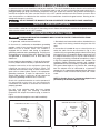
(Model 28-348)
PART NO. 426-03-651-0013 - 1-31-06
Copyright © 2006 Delta Machinery
To learn more about DELTA MACHINERY
visit our website at: www.deltamachinery.com.
For Parts, Service, Warranty or other Assistance,
please call
1-800-223-7278 (In Canada call 1-800-463-3582).
INSTRUCTION MANUAL
14" Metal/Wood Cutting
Band Saw
SAFETY GUIDELINES - DEFINITIONS
This manual contains information that is important for you to know and understand. This information relates to protecting YOUR SAFETY and PREVENTING EQUIPMENT PROBLEMS. To help you recognize this information, we use the
symbols to the right. Please read the manual and pay attention to these sections.
Indicates an imminently hazardous situation which, if not avoided, will result in death or serious injury.
Indicates a potentially hazardous situation which, if not avoided, could result in death or serious injury.
Indicates a potentially hazardous situation which, if not avoided, may result in minor or moderate injury.
Used without the safety alert symbol indicates potentially hazardous situation which, if not avoided, may
result in property damage.
SOME DUST CREATED BY POWER SANDING, SAWING, GRINDING, DRILLING, AND OTHER
CONSTRUCTION ACTIVITIES contains chemicals known to cause cancer, birth defects or other reproductive harm.
Some examples of these chemicals are:
· lead from lead-based paints,
· crystalline silica from bricks and cement and other masonry products, and
· arsenic and chromium from chemically-treated lumber.
Your risk from these exposures varies, depending on how often you do this type of work. To reduce your exposure to
these chemicals: work in a well ventilated area, and work with approved safety equipment, always wear MSHA/NIOSH
approved, properly fitting face mask or respirator when using such tools.
GENERAL SAFETY RULES
READ AND UNDERSTAND ALL WARNINGS AND OPERATING INSTRUCTIONS BEFORE
USING THIS EQUIPMENT. Failure to follow all instructions listed below, may result in electric shock,
fire, and/or serious personal injury or property damage.
IMPORTANT SAFETY INSTRUCTIONS
Woodworking can be dangerous if safe and proper operating procedures are not followed. As with all machinery, there
are certain hazards involved with the operation of the product. Using the machine with respect and caution will
considerably lessen the possibility of personal injury. However, if normal safety precautions are overlooked or ignored,
personal injury to the operator may result. Safety equipment such as guards, push sticks, hold-downs, featherboards,
goggles, dust masks and hearing protection can reduce your potential for injury. But even the best guard won’t make
up for poor judgment, carelessness or inattention. Always use common sense and exercise caution in the workshop.
If a procedure feels dangerous, don’t try it. Figure out an alternative procedure that feels safer. REMEMBER: Your
personal safety is your responsibility. For additional information please visit our website www.deltamachinery.com.
This machine was designed for certain applications only. Delta Machinery strongly recommends that this
machine not be modified and/or used for any application other than that for which it was designed. If you have any
questions relative to a particular application, DO NOT use the machine until you have first contacted Delta to determine
if it can or should be performed on the product.
Technical Service Manager
Delta Machinery
4825 Highway 45 North
Jackson, TN 38305
(IN CANADA: 505 SOUTHGATE DRIVE, GUELPH, ONTARIO N1H 6M7)
2
FAILURE TO FOLLOW THESE RULES MAY RESULT IN SERIOUS PERSONAL INJURY.
1. FOR YOUR OWN SAFETY, READ THE INSTRUCTION
MANUAL BEFORE OPERATING THE MACHINE.
Learning the machine’s application, limitations, and
specific hazards will greatly minimize the possibility of
accidents and injury.
2. WEAR EYE PROTECTION. ALWAYS USE SAFETY
GLASSES. Also use face or dust mask if cutting
operation is dusty. Everyday eyeglasses are NOT safety
glasses. USE CERTIFIED SAFETY EQUIPMENT. Eye
protection equipment should comply with ANSI Z87.1
standards, hearing equipment should comply with
ANSI S3.19 standards, and dust mask protection
should comply with MSHA/NIOSH certified respirator
standards. Splinters, air-borne debris, and dust can
cause irritation, injury, and/or illness.
3. WEAR PROPER APPAREL. Do not wear loose
clothing, gloves, neckties, rings, bracelets, or other
jewelry which may get caught in moving parts. Nonslip
footwear is recommended. Wear protective hair
covering to contain long hair.
4. DO NOT USE THE MACHINE IN A DANGEROUS
ENVIRONMENT. The use of power tools in damp or
wet locations or in rain can cause shock or
electrocution. Keep your work area well-lit to prevent
tripping or placing arms, hands, and fingers in danger.
5. MAINTAIN ALL TOOLS AND MACHINES IN PEAK
CONDITION. Keep tools sharp and clean for best and safest
performance. Follow instructions for lubricating and changing
accessories. Poorly maintained tools and machines can further
damage the tool or machine and/or cause injury.
6. CHECK FOR DAMAGED PARTS. Before using the
machine, check for any damaged parts. Check for
alignment of moving parts, binding of moving parts,
breakage of parts, and any other conditions that may
affect its operation. A guard or any other part that is
damaged should be properly repaired or replaced.
Damaged parts can cause further damage to the
machine and/or injury.
7. KEEP THE WORK AREA CLEAN. Cluttered areas and
benches invite accidents.
8. KEEP CHILDREN AND VISITORS AWAY. Your shop is a
potentially dangerous environment. Children and visitors can
be injured.
9. REDUCE THE RISK OF UNINTENTIONAL STARTING.
Make sure that the switch is in the “OFF” position
before plugging in the power cord. In the event of a
power failure, move the switch to the “OFF” position.
An accidental start-up can cause injury.
10. USE THE GUARDS. Check to see that all guards are in
place, secured, and working correctly to prevent injury.
11. REMOVE ADJUSTING KEYS AND WRENCHES
BEFORE STARTING THE MACHINE. Tools, scrap
pieces, and other debris can be thrown at high speed,
causing injury.
12. USE THE RIGHT MACHINE. Don’t force a machine or
an attachment to do a job for which it was not
designed. Damage to the machine and/or injury may
result.
13. USE RECOMMENDED ACCESSORIES. The use of
accessories and attachments not recommended by
Delta may cause damage to the machine or injury to the
user.
14. USE THE PROPER EXTENSION CORD. Make sure
your extension cord is in good condition. When using
an extension cord, be sure to use one heavy enough to
carry the current your product will draw. An undersized
cord will cause a drop in line voltage, resulting in loss of
power and overheating. See the Extension Cord Chart
for the correct size depending on the cord length and
nameplate ampere rating. If in doubt, use the next
heavier gauge. The smaller the gauge number, the
heavier the cord.
15. SECURE THE WORKPIECE. Use clamps or a vise to hold
the workpiece when practical. Loss of control of a
workpiece can cause injury.
16. FEED THE WORKPIECE AGAINST THE DIRECTION OF
THE ROTATION OF THE BLADE, CUTTER, OR ABRASIVE
SURFACE. Feeding it from the other direction will cause
the workpiece to be thrown out at high speed.
17. DON’T FORCE THE WORKPIECE ON THE MACHINE.
Damage to the machine and/or injury may result.
18. DON’T OVERREACH. Loss of balance can make you
fall into a working machine, causing injury.
19. NEVER STAND ON THE MACHINE. Injury could occur if the
tool tips, or if you accidentally contact the cutting tool.
20. NEVER LEAVE THE MACHINE RUNNING UNATTENDED.
TURN THE POWER OFF. Don’t leave the machine until it
comes to a complete stop. A child or visitor could be injured.
21. TURN THE MACHINE “OFF”, AND DISCONNECT THE
MACHINE FROM THE POWER SOURCE before installing
or removing accessories, before adjusting or changing
set-ups, or when making repairs. An accidental start-up
can cause injury.
22. MAKE YOUR WORKSHOP CHILDPROOF WITH
PADLOCKS, MASTER SWITCHES, OR BY
REMOVING STARTER KEYS. The accidental start-up
of a machine by a child or visitor could cause injury.
23. STAY ALERT, WATCH WHAT YOU ARE DOING, AND
USE COMMON SENSE. DO NOT USE THE
MACHINE WHEN YOU ARE TIRED OR UNDER THE
INFLUENCE OF DRUGS, ALCOHOL, OR MEDICATION. A moment of inattention while operating power
tools may result in injury.
24. THE DUST GENERATED by certain woods and wood
products can be injurious to your health. Always
operate machinery in well-ventilated areas, and provide
for proper dust removal. Use wood dust collection
systems whenever possible.
3
ADDITIONAL SAFETY RULES
FOR BAND SAWS
FAILURE TO FOLLOW THESE RULES MAY RESULT IN SERIOUS PERSONAL INJURY.
1.
2.
3.
4.
5.
6.
7.
8.
9.
10.
11.
12.
13.
DO NOT OPERATE THIS MACHINE UNTIL it is
assembled and installed according to the
instructions.
OBTAIN ADVICE from your supervisor,
instructor, or another qualified person if you are
not familiar with the operation of this tool.
FOLLOW ALL WIRING CODES and recommended
electrical connections.
USE THE GUARDS WHENEVER POSSIBLE. Check
to see that they are in place, properly adjusted,
secured, and working correctly.
USE PROPER BLADE SIZE and type.
ADJUST THE UPPER BLADE GUIDE AND
GUARD so that it is about 1/8" above the
workpiece.
PROPERLY ADJUST the blade tension, tracking,
blade guides, and blade support bearings.
KEEP ARMS, HANDS, AND FINGERS away from
the blade.
AVOID AWKWARD OPERATIONS and hand
positions where a sudden slip could cause a hand
to move into the blade.
NEVER START THE MACHINE before clearing the
table of all objects (tools, scrap pieces, etc.).
NEVER START THE MACHINE with the workpiece
against the blade.
HOLD WORKPIECE FIRMLY against the table. DO
NOT attempt to saw a workpiece that does not have
a flat surface against the table.
HOLD WORKPIECE FIRMLY and feed into blade at
a moderate speed.
14. NEVER REACH UNDER THE TABLE while the
machine is running.
15. TURN THE MACHINE “OFF” to back out of an
uncompleted or jammed cut.
16. MAKE “RELIEF” CUTS prior to cutting long curves.
17. TURN THE MACHINE “OFF” and wait for the blade
to stop prior to cleaning the blade area, removing
debris near the blade, removing or securing
workpiece, or changing the angle of the table. A
coasting blade can be dangerous.
18. NEVER PERFORM LAYOUT, ASSEMBLY, or setup work on the table/work area when the machine is
running.
19. TURN THE MACHINE “OFF” AND DISCONNECT
THE MACHINE from the power source before
installing or removing accessories, before adjusting
or changing set-ups, or when making repairs.
20. TURN THE MACHINE “OFF”, disconnect the
machine from the power source, and clean the
table/work area before leaving the machine. LOCK
THE SWITCH IN THE “OFF” POSITION to prevent
unauthorized use.
21. ADDITIONAL INFORMATION regarding the safe
and proper operation of power tools (i.e. a safety
video) is available from the Power Tool Institute,
1300 Sumner Avenue, Cleveland, OH 44115-2851
(www.powertoolinstitute.com). Information is also
available from the National Safety Council, 1121
Spring Lake Drive, Itasca, IL 60143-3201. Please
refer to the American National Standards Institute
ANSI 01.1 Safety Requirements for Woodworking
Machines and the U.S. Department of Labor OSHA
1910.213 Regulations.
SAVE THESE INSTRUCTIONS.
Refer to them often and use them to instruct others.
4
POWER CONNECTIONS
A separate electrical circuit should be used for your machines. This circuit should not be less than #12 wire and should
be protected with a 20 Amp time lag fuse. If an extension cord is used, use only 3-wire extension cords which have 3prong grounding type plugs and matching receptacle which will accept the machine’s plug. Before connecting the
machine to the power line, make sure the switch is in the “OFF” position and be sure that the electric current is of the
same characteristics as indicated on the machine. All line connections should make good contact. Running on low
voltage will damage the machine.
DO NOT EXPOSE THE MACHINE TO RAIN OR OPERATE THE MACHINE IN DAMP LOCATIONS.
MOTOR SPECIFICATIONS
Your machine is wired for 120 volt, 60 HZ alternating current. Before connecting the machine to the power source,
make sure the switch is in the “OFF” position.
GROUNDING INSTRUCTIONS
THIS MACHINE MUST BE GROUNDED WHILE IN USE TO PROTECT THE OPERATOR FROM
ELECTRIC SHOCK.
1. All grounded, cord-connected machines:
2. Grounded, cord-connected machines intended for use
on a supply circuit having a nominal rating less than 150
volts:
In the event of a malfunction or breakdown, grounding
provides a path of least resistance for electric current to
reduce the risk of electric shock. This machine is
equipped with an electric cord having an equipmentgrounding conductor and a grounding plug. The plug must
be plugged into a matching outlet that is properly installed
and grounded in accordance with all local codes and
ordinances.
If the machine is intended for use on a circuit that has an
outlet that looks like the one illustrated in Fig. A, the
machine will have a grounding plug that looks like the plug
illustrated in Fig. A. A temporary adapter, which looks like
the adapter illustrated in Fig. B, may be used to connect
this plug to a matching 2-conductor receptacle as shown
in Fig. B if a properly grounded outlet is not available. The
temporary adapter should be used only until a properly
grounded outlet can be installed by a qualified electrician.
The green-colored rigid ear, lug, and the like, extending
from the adapter must be connected to a permanent
ground such as a properly grounded outlet box. Whenever
the adapter is used, it must be held in place with a metal
screw.
Do not modify the plug provided - if it will not fit the outlet,
have the proper outlet installed by a qualified electrician.
Improper connection of the equipment-grounding
conductor can result in risk of electric shock. The
conductor with insulation having an outer surface that is
green with or without yellow stripes is the equipmentgrounding conductor. If repair or replacement of the
electric cord or plug is necessary, do not connect the
equipment-grounding conductor to a live terminal.
NOTE: In Canada, the use of a temporary adapter is not
permitted by the Canadian Electric Code.
Check with a qualified electrician or service personnel if
t h e g ro u n d i n g i n s t r u c t i o n s a re n o t c o m p l e t e l y
understood, or if in doubt as to whether the machine is
properly grounded.
Use only 3-wire extension cords that have 3-prong
grounding type plugs and matching 3-conductor
receptacles that accept the machine’s plug, as shown in
Fig. A.
Repair or replace damaged or worn cord immediately.
GROUNDED OUTLET BOX
GROUNDED OUTLET BOX
GROUNDING
MEANS
CURRENT
CARRYING
PRONGS
ADAPTER
GROUNDING BLADE
IS LONGEST OF THE 3 BLADES
Fig. A
5
Fig. B
3. Grounded, cord-connected machines intended for
use on a supply circuit having a nominal rating between
150 - 250 volts, inclusive:
If the machine is intended for use on a circuit that has an
outlet that looks like the one illustrated in Fig. C, the
machine will have a grounding plug that looks like the
plug illustrated in Fig. C. Make sure the machine is
connected to an outlet having the same configuration as
the plug. No adapter is available or should be used with
this machine. If the machine must be re-connected for
use on a different type of electric circuit, the reconnection should be made by qualified service
personnel; and after re-connection, the machine should
comply with all local codes and ordinances.
CURRENT
CARRYING
PRONGS
GROUNDED OUTLET BOX
GROUNDING BLADE
IS LONGEST OF THE 3 BLADES
Fig. C
IN ALL CASES, MAKE CERTAIN
THE
R E C E P TA C L E I N Q U E S T I O N I S P R O P E R LY
G R O U N D E D . I F Y O U A R E N O T S U R E H AV E A
QUALIFIED ELECTRICIAN CHECK THE
RECEPTACLE.
EXTENSION CORDS
Use proper extension cords. Make sure your extension cord is in good condition and is a 3-wire
extension cord which has a 3-prong grounding type plug and matching receptacle which will accept the machine’s
plug. When using an extension cord, be sure to use one heavy enough to carry the current of the machine. An
undersized cord will cause a drop in line voltage, resulting in loss of power and overheating. Fig. D, shows the correct
gauge to use depending on the cord length. If in doubt, use the next heavier gauge. The smaller the gauge number,
the heavier the cord.
MINIMUM GAUGE EXTENSION CORD
MINIMUM GAUGE EXTENSION CORD
RECOMMENDED SIZES FOR USE WITH STATIONARY ELECTRIC MACHINES
RECOMMENDED SIZES FOR USE WITH STATIONARY ELECTRIC MACHINES
Ampere
Rating
Volts
Total Length
of Cord in Feet
Ampere
Rating
Gauge of
Extension Cord
Volts
Total Length
of Cord in Feet
Gauge of
Extension Cord
0-6
0-6
0-6
0-6
120
120
120
120
up to 25
25-50
50-100
100-150
18 AWG
16 AWG
16 AWG
14 AWG
0-6
0-6
0-6
0-6
240
240
240
240
up to 50
50-100
100-200
200-300
18 AWG
16 AWG
16 AWG
14 AWG
6-10
6-10
6-10
6-10
120
120
120
120
up to 25
25-50
50-100
100-150
18 AWG
16 AWG
14 AWG
12 AWG
6-10
6-10
6-10
6-10
240
240
240
240
up to 50
50-100
100-200
200-300
18 AWG
16 AWG
14 AWG
12 AWG
10-12
10-12
10-12
10-12
120
120
120
120
up to 25
25-50
50-100
100-150
16 AWG
16 AWG
14 AWG
12 AWG
10-12
10-12
10-12
10-12
240
240
240
240
up to 50
50-100
100-200
200-300
16 AWG
16 AWG
14 AWG
12 AWG
12-16
12-16
12-16
120
120
120
up to 25
25-50
14 AWG
12 AWG
12-16
12-16
12-16
240
240
240
up to 50
50-100
14 AWG
12 AWG
GREATER THAN 50 FEET NOT RECOMMENDED
GREATER THAN 100 FEET NOT RECOMMENDED
Fig. D
Fig. D
FUNCTIONAL DESCRIPTION
FOREWORD
Delta Model 28-348 is a 14" Metal and Wood Cutting Band Saw. This machine has speeds of 40, 60, 85, 115, 160, 220,
335, and 3000 SFM. Its blade to frame capacity is 13-3/4" and its under-guide and wheel capacity is 6-1/4".The band
saw has a quick tensioning blade mechanism for ease of changing blades and applying tension to the blade. The Delta
Model 28-348 has a large 16"x16" cast iron table that can be tilted 45 degrees to the right and 8 degrees to the left. The
band saw also comes with a 4" O.D. dust port for connecting the band saw to a dust collector.
NOTICE: THE MANUAL COVER PHOTO ILLUSTRATES THE CURRENT PRODUCTION
MODEL. ALL OTHER ILLUSTRATIONS ARE REPRESENTATIVE ONLY AND MAY NOT
DEPICT THE ACTUAL COLOR, LABELING OR ACCESSORIES AND MAY BE INTENDED TO
ILLUSTRATE TECHNIQUE ONLY.
6
UNPACKING AND CLEANING
Carefully unpack the machine and all loose items from the shipping container(s). Remove the protective coating from
all unpainted surfaces. This coating may be removed with a soft cloth moistened with kerosene (do not use acetone,
gasoline or lacquer thinner for this purpose). After cleaning, cover the unpainted surfaces with a good quality household
floor paste wax.
1. Remove the cardboard box from around the packing
skid (A) Fig. 2.
2. Remove the two bolts (B) Fig. 2, with a 1/2" wrench,
that attach the motor to the packing skid (A)
A
B
Fig. 2
3. Remove the bolts that attach the stand (C) Fig. 3,
and the saw (D) to the the packing skid (A) with a 3/8"
wrench.
D
C
A
Fig. 3
7
BAND SAW PARTS
7
6
8
2
1
9
10
12
13
14
11
15
3
16
17
18
4
5
24
19
20
21
22
23
25
27
26
29
Fig. 4
28
Fig. 5
1. Saw
18. #10-32x1/2" Pan Head Screw (4)
2. Cabinet
19. 5/16" Flat Washer (4)
3. Dust Chute
20. 7/16-14 Jam Nut (2)
4. Top Plate
21. 7/16-14 Locknut (2)
5. Stand Door
22. 5/16-18 Flange Hex Nut (20)
6. Motor Assembly
23. #10-32 Hex Nut (4)
7. Table
24. Table Handle (2)
8. Long V-Belt
25. Hinge Pin (2)
9. Blade
26. Door Latch
10. Dust Port
27. Hinge (2)
11. Table Insert
28. 3/4" to 5/8" Reducing Bushing
12. Short V-Belt
29. Key
13. Motor Bracket (2)
14. Motor Pulley
15. 5/16-18x1½" Hex Head Screw (4)
16. 5/16-18x3/4" Carriage Head Bolt (16)
17. #10-24x1/2" Socket Head Cap Screw (8)
8
ASSEMBLY
FOR YOUR OWN SAFETY, DO NOT CONNECT THE MACHINE TO THE POWER SOURCE UNTIL
THE MACHINE IS COMPLETELY ASSEMBLED AND YOU READ AND UNDERSTAND THE ENTIRE
INSTRUCTION MANUAL.
MOTOR BRACKET
TO CABINET
1. Place the cabinet on its side as shown in Fig. 6.
1
2. Align the two holes in the motor bracket (A) Fig. 7,
with the two holes in the cabinet. NOTE: ATTACH
MOTOR BRACKETS TO HOLES #2 AND 4 IN FRONT
CABINET FLANGE (D) FIG. 6, AND HOLES #4 AND 6
IN REAR CABINET FLANGE (E).
2 34 5
6
2 3
4
E
1
D
NOTE: MAKE SURE THE SLOTS (C) FIG. 7, IN THE
MOTOR BRACKET (A), ARE POSITIONED CLOSER
TO THE OPENING OF THE CABINET (D) THAN THE
BACK PANEL (E) OF THE CABINET.
Fig. 6
E
3. Insert 5/16-18x3/4" carriage head bolts through the
holes in the motor brackets (A) Fig. 7, and the holes in
the cabinet.
4. Thread 5/16-18 flange hex nuts onto the screws and
tighten securely.
D
C
C
A
Fig. 7
MOTOR TO
MOTOR BRACKET
B
1. Place the motor (B) Fig. 8, on the motor brackets (A).
Align the holes in the motor mounting plate with the
holes on the motor brackets.
A
2. Insert 5/16-18x3/4" carriage head bolts through the
holes in the motor brackets and the holes in the motor
mounting plate.
Fig. 8
3. Thread 5/16-18 flange hex nuts on to screws.
NOTE: DO NOT COMPLETELY TIGHTEN THE
HARDWARE AT THIS TIME.
4. Place cabinet on its base as shown in Fig. 9.
Fig. 9
9
TOP PLATE TO CABINET
G
NOTE: IF YOUR MACHINE IS SUPPLIED WITH AN
LVC STARTER BOX, PLEASE REFER TO THE
SUPPLEMENTAL INSTRUCTION SHEET FOR
MOUNTING THE LVC BOX TO THE STAND. THEN
PROCEED AS FOLLOWS.
F
H
A
1. Place the top plate (A) Fig. 10, on the top of the
cabinet (B). NOTE: PLACE THE SWITCH CORD (F)
FIG. 10, THROUGH THE SLOTTED HOLE (G) IN THE
TOP PLATE (A) AND INSERT PLASTIC BUSHING (H)
INTO THE SLOTTED HOLE (G).
B
Fig. 10
2. Align the six square holes on the top plate (A) Fig.
10, with the holes in the cabinet (B).
3. Align the two square holes on the side of the plate
(A) Fig. 10, with the two holes on the side of the cabinet
(B).
A
4. Insert 5/16-18x3/4" carriage head bolts through the
top plate and the cabinet. Thread 5/16-18 flange hex
nuts on to screws.
5. Make sure the door opening is at least 13" wide
before tightening the screws. If the door opening is not
at least 13" wide, spread the door opening and tighten
the hardware when the opening is at least 13" wide.
DUST CHUTE
Fig. 11
1. Insert the dust chute from inside the stand through
the opening (A) Fig. 11, in the top of the stand.
B
C
NOTE: MAKE SURE THAT THE MOTOR CORD IS
BEHIND THE DUST CHUTE.
NOTE: MAKE SURE THE TAB (B) FIG. 12, ON THE
DUST CHUTE, ENGAGES THE CUTOUT (C) IN THE
TOP OF THE STAND.
2. Align the two slotted holes (D) Fig. 13, in the bottom
of the dust chute with the two holes (E) Fig. 14, in the
stand.
Fig. 12
D
E
Fig. 13
Fig. 14
10
BAND SAW USED WITH A DUST
COLLECTOR
B
B
3. If you are going to use your band saw with a dust
collector, attach the dust port as follows:
A
A. Align the four holes in the dust port (A) Fig. 15,
with the four holes in the side of the stand.
B. NOTE: THE DUST CHUTE WILL ONLY BE
ATTACHED AT THE TWO BOTTOM HOLES
(C) IN THE DUST PORT.
C
C
Fig. 15
C. Insert #10-32x1/2" pan head screws through
the four holes (B) and (C) Fig. 15, in the dust
port, and cabinet. Thread #10-32 hex nuts onto
the screws, and tighten securely.
BAND SAW USED WITHOUT A
DUST COLLECTOR
3. If you are not going to use a dust collector with your
band saw proceed as follows:
A
Insert #10-32x1/2" pan head screws through
holes (A) Fig. 16, in the cabinet and dust chute.
Thread #10-32 hex nuts onto the screws, and
tighten securely.
Fig. 16
STAND DOOR TO STAND
1. Align the two holes in the hinge pins (A) Figs. 17 and
18, with the two holes on the cabinet. NOTE: MAKE
SURE THE HINGE PINS (A) ARE POINTED UP AS
SHOWN IN FIGS. 17 AND 18.
A
Fig. 17
2. Insert #10-24x1/2" socket head cap screws through
the holes in the cabinet, (from the inside of the stand),
and thread the screw into the hinge pins.
NOTE: DO NOT COMPLETELY TIGHTEN THE
SCREWS AT THIS TIME.
3. Make sure the two hinge pins (A) are aligned with
each other by using a straight edge as shown in Fig18.
A
4. Tighten the four screws securely.
Fig. 18
11
5. Align the two holes in the hinge (C) Fig. 19, with the
two holes in the cabinet door (D). MAKE SURE THAT
THE HINGE OPENING IS POINTING DOWN.
C
6. Insert #10-24x1/2" socket head cap screws through
the holes in the door, and thread the screws into the
holes in the hinge. NOTE: DO NOT COMPLETELY
TIGHTEN THE SCREWS AT THIS TIME.
D
7. Make sure the two hinges are aligned with each
other by using a straight edge as shown in Fig. 20.
8. Tighten the four screws securely.
Fig. 19
Fig. 20
9. Insert the door latch (F) Fig. 21, from the outside,
through the hole in the door.
10. Push down on the door latch to snap the latch in
place.
F
Fig. 21
11. Slide the two hinges (C) Fig. 22, on the door, over
the two hinge pins (A) on the cabinet.
C
12. To open or shut the door, slide the latch away from
the cabinet and pull or push the door.
A
C
A
Fig. 22
12
SAW TO STAND
A
THE BAND SAW IS VERY HEAVY. USE A
HELPER WHEN ATTACHING THE SAW TO THE
CABINET.
1. Place the band saw on top of the cabinet as shown
in Fig. 23. NOTE: MAKE SURE THE PULLEY (A) FIG.
23, IS ON THE SIDE OF THE CABINET WITH THE
BELT OPENING (B).
2. Align the four holes in the saw with the four holes in
the top of the cabinet.
3. Place 5/16" flat washers on a 5/16-18x1½" hex
head screws. Insert the screws through the holes (C) in
the saw and the cabinet.
4. Thread 5/16-18 hex nuts on the screws and tighten
securely.
B
C
Fig. 23
MOTOR PULLEY
NOTE: Both the motor pulley (A) Fig. 24, and the
gearbox pulley (B) are four-step pulleys and should
always be attached inverted to each other.
Check to see if the gear box pulley (B) is attached with
the largest step of the pulley in the “in” or “out” position.
In this case, the largest step of the gear box pulley (B) is
in the “out” position. Attach the motor pulley (A) to the
motor shaft with the largest step of the motor pulley in
the “in” position.
1. Place the 3/4" to 5/8" reducing bushing on the
motor shaft. Align the split in the reducer with the key
way slot.
2. Place the key in the motor shaft.
3. Position the pulley on the shaft. Line it up with the
key. Secure with two 5/16-18x5/16" set screws.
B
A
Fig. 24
BELT TO SAW AND MOTOR
PULLEY
1.
DISCONNECT MACHINE FROM POWER
SOURCE.
2. Use a straight edge to align the inside grooves of
the pulleys (A) and (B) Fig. 24 to the inside edge of the
drive pulley (C). The pulleys can be moved in or out on
the shafts and the motor can also be moved.
C
B
3. Place the longer V-Belt on the inside groove of the
motor (A) and the drive pulley (C) Fig. 25. Place the
shorter V-Belt on any one of the remaining three grooves
on the motor pulley (A) and the corresponding groove on
the gear box pulley (B). (Fig. 25 shows belts in place.)
4. Adjust the belt tension by raising or lowering the
motor on the motor mounting brackets (A) Fig. 7. Keep
the pulleys in alignment when performing this operation.
Proper tension is 1/4" deflection at the center of the belt
with light finger pressure.
A
Fig. 25
13
TABLE TO SAW
C
1. Align the two table studs (A) Fig. 27, on the bottom
of the table, with the two holes in the trunnion
assemblies (B). Place table on trunnion assemblies.
NOTE: MAKE SURE THE SLOT (C) FIG. 27, IN THE
TABLE IS FACING AWAY FROM THE ARM (D).
A
D
A
B
B
2. Thread a 7/16" jam nut (C) Fig. 28 onto each table
stud and tighten securely.
Fig. 27
C
C
Fig. 28
3. Place table handles (H) on each stud as shown in
Fig. 29. NOTE: MAKE SURE THE TABLE HANDLES
ARE POSITIONED AS SHOWN IN FIG. 29.
H
H
Fig. 29
4. Thread a 7/16" locknut (D) Fig. 30, onto each stud,
up to the table handle and then loosen a 1/2 turn.
D
D
Fig. 30
14
BLADE TO SAW
B
D
THE 14" BAND SAW USES 93½"
LENGTH BLADES.
E
1. Remove the table pin (A) Fig. 31 from the table.
2. Open the two wheel guard doors (B) Fig. 31, and the
blade guard door (C).
A
B
3. Make sure the quick tension lever (D) Fig. 31, is
positioned to the right of the machine as shown.
C
Fig. 31
4. MAKE SURE THAT THE TEETH ON THE BLADE
ARE POINTING DOWN TOWARD THE TABLE WHEN
INSTALLED AS SHOWN IN FIG. 33. IF NOT, TURN
BLADE INSIDE OUT. Slide the band saw blade, (teeth
facing out), through the slot (E) Fig. 31, in the band saw
table.
D
5. Place the blade around the two wheel assemblies
(A) Fig. 32.
A
6. Replace the table pin (A) Fig. 31. Table alignment pin
should be re-seated by gently tapping it with a hammer.
7. Close the two wheel guard doors (B) Fig. 31, and the
blade guard door (C).
8. Move the quick tension lever (D) Fig. 32, to the left
position (when facing the rear of the saw) to put tension
on the blade as shown.
Fig. 32
9. See the section “OPERATING CONTROLS AND
ADJUSTMENTS” to adjust blade tension and tracking.
TABLE INSERT
Place table insert (A) Fig. 33, in opening of table. NOTE:
A tab (B) is provided on insert that engages with notch
(C) in table opening.
C
B
A
Fig. 33
15
ON / OFF SWITCH
TO STAND
A
B
1. Remove the two outer hex nuts and lock washers (A)
Fig. 34 from the switch box (B).
A
Fig. 34
2. Insert two screws (C) Fig. 35, located on back of
switch box, into two holes (D) located in the band saw
arm.
D
C
Fig. 35
3. Use the two nuts and lockwashers (L) Fig. 36,
removed in STEP 1, to fasten the switch box to the
bandsaw arm.
L
Fig. 36
4. Remove the screw and cable clamp (E) Fig. 37 from
the lower arm of the band saw.
F
5. Insert the switch cord and power cord (F) Fig. 37
into the clamp (E), and fasten to the bandsaw.
E
Fig. 37
16
OPERATING CONTROLS AND ADJUSTMENTS
STARTING AND
STOPPING SAW
The power switch is located on the left side of the
machine. To turn the machine “ON”, push the green
start button (A) Fig. 41. To turn the machine “OFF”, push
the red stop button (B).
A
B
Fig. 41
LOCKING SWITCH IN THE
“OFF” POSITION
IMPORTANT: When the tool is not in use, the switch
should be locked in the “OFF” position to prevent
unauthorized use, using a padlock (C) Fig. 42 with a
3/16" diameter shackle.
C
Fig. 42
TILTING THE TABLE
1.
DISCONNECT MACHINE
POWER SOURCE.
FROM
D
2. The table on the band saw can be tilted 45 degrees
to the right and 9 degrees to the left. To tilt the table to
the right, loosen the two clamp handles (A) Fig. 43, tilt
the table to the desired angle as shown on the scale (D)
Figs. 43 and 44, and tighten two locking handles (A) Fig.
43.
A
A
Fig. 43
3. To tilt the table to the left, loosen the two locking
handles (A) Fig. 43, and tilt the table to the right until the
table stops (B) Fig. 44 can be accessed. Rotate the table
stop (B) Fig. 44, and tilt the table to the left. Tighten the
two locking handles (A) Fig. 43.
B
D
Fig. 44
17
ADJUSTING THE
TABLE STOPS
To adjust the 90 degree stop
1.
DISCONNECT MACHINE
POWER SOURCE.
B
FROM
F
2. Loosen the table clamp handles (A) Fig. 43, and tilt
the table to the right.
3. Rotate the stop (B) Fig. 45 out of the way.
Fig. 45
4. Place a square (G) Fig. 46, on the table and set
blade square to table.
5. Tighten table clamp handles (A) Fig. 43.
G
6. Rotate the stop (B) Fig. 45, until the tallest screw is
under the table.
7. Turn the screw up or down until the screw touches
the table skirt.
8. Loosen screw (K) Fig. 47 and move pointer (J) to the
“0”, and tighten screw (K).
Fig. 46
To set the adjustable stops:
The adjustable stops (quick stop table presets) can be
used to set the table any where from 0 to 9 degrees left
for beveling operations.
1.
J
DISCONNECT MACHINE
POWER SOURCE.
FROM
K
2. Loosen the two clamp handles (A) Fig. 43.
3. Tilt the table to the right, and turn the stop until
either stop screw (M) or (N) Fig. 48, is under the table
skirt.
Fig. 47
4. Tilt the table to the left until it rests on the selected
stop screw (M) or (N) Fig. 48.
5. The angle can be set by turning the stop screw and
checking the angle on the side of the scale with pointer
(J) Fig. 47.
M
N
6. Adjust the other stop screw (M) or (N) Fig. 48, in the
same manner.
Fig. 48
18
ADJUSTING BLADE
TENSION
A
The band saw is equipped with a quick tensioning blade
mechanism. To apply tension, move the tension handle
(A) to the left as shown. To release tension, move the
tension lever lock (B) Fig. 49 up, and move the tension
handle (A) to the right as shown in Fig. 50.
B
To adjust the blade tension proceed as follows:
1.
DISCONNECT MACHINE
POWER SOURCE.
FROM
Fig. 49
2. Push up on the blade tension lever lock (B) Fig. 49,
move the blade tension handle to the right, to remove
the blade tension.
3. The blade tension handle can be set for blade widths
of 3/4", 1/2", 3/8", 1/4", and 1/8".
C
A
4. Pull out on the blade tension handle (A) Fig. 50, and
turn the the tension lever until the appropriate width of
the blade is shown on the top of the blade tension lever
scale (C) and then release the blade tension lever
handle.
D
5. Move the blade tension handle to the left until the
lever lock (B) Fig. 49 engages the blade tension lever
handle (A).
Fig. 50
6. The band saw blade tension can be fine tuned by
turning adjustment nut (N) Fig. 51, while the blade is
tensioned.
7. A series of graduations is located on the back of the
upper wheel slide bracket (T) Fig. 51. These graduations
indicate the proper tension for various widths of blades.
B
C
NOTE: THESE GRADUATIONS ARE CORRECT FOR
AVERAGE WORK, AND WILL NOT BE AFFECTED BY
REBRAZING OF THE SAW BLADE.
T
N
WHEN CUTTING THIN PIECES, 3/4" OR
LESS, SET THE BLADE TENSION BELOW THE
MAXIMUM SETTING FOR BLADE WIDTH, TO
EXTEND BLADE LIFE.
Fig. 51
OVER-STRAINING IS A COMMON CAUSE
OF BLADE BREAKAGE AND OTHER UNSATISFACTORY
BLADE PERFORMANCE. RELEASE THE TENSION
WHEN THE TOOL IS NOT IN USE.
19
TRACKING THE BLADE
DISCONNECT MACHINE FROM POWER
SOURCE.
BEFORE TRACKING THE BLADE,
MAKE SURE THAT THE BLADE GUIDES AND BLADE
SUPPORT BEARINGS ARE CLEAR OF THE BLADE.
After applying tension to the blade, rotate the upper
wheel slowly forward by hand and observe the blade’s
movement. The blade (A) Fig. 52 should travel in the
center of the upper tire. If the blade creeps toward the
front edge, loosen the wing nut (B) Fig. 51, and turn the
thumb screw (C) clockwise. This action draws the blade
toward the center of the tire. If the blade creeps toward
the back edge, turn the thumb screw in the opposite
direction. Adjust the thumb screw (C) Fig. 51 only a
fraction of a turn each time.
NEVER TRACK THE BLADE WHILE
THE TOOL IS RUNNING.
After the blade is tracking in the center of the tires,
tighten the wing nut (B) Fig. 51.
A
Fig. 52
VERTICAL ADJUSTMENT OF
THE UPPER BLADE GUIDE AND
GUARD ASSEMBLY
B
DISCONNECT MACHINE FROM POWER
SOURCE.
Adjust the blade guides and bearings according to the
following instructions.
Set the upper blade guide and guard assembly (A) Fig.
53 as close as possible to the top surface of the
workpiece. Loosen the lock knob (B) and move the
guide assembly (A) to the desired position.
A
Fig. 53
ADJUSTING THE UPPER
BLADE GUIDES AND BLADE
SUPPORT BEARING
Adjust the upper blade guides and blade support
bearings ONLY AFTER the blade has the correct tension
and is tracking properly. To adjust, proceed as follows:
1.
DISCONNECT MACHINE FROM
POWER SOURCE
2. Make sure that the bottom blade guides and support
bearings are not touching the blade.
3. Check the upper blade guide assembly. The blade
guides (A) Fig. 54 should be parallel to the blade. To
adjust, loosen the screw (B) and rotate the complete
guide assembly (C). When the blade guides are parallel
with the blade, tighten the screw (B).
4. Adjust the guides (A) Fig. 55 so that the front edge of
the guides are just behind the “gullets” of the saw teeth.
The complete guide block bracket can be moved in or
out by loosening the thumb screw (C) and turning the
knurled knob (D) Fig. 55. When the guides (A) are set
properly, tighten thumb screw (C).
B
C
A
Fig. 54
20
5. Two set screws (B) Fig. 55 hold the upper blade
guides (A) in place. Loosen the set screws (B) to move
the guides (A). Place them as close as possible to the
side of the blade. (Be careful not to pinch the blade).
Tighten the screws (B).
F
6. When the blade guide wears to a point that it cannot
be adjusted close to the blade, loosen screw (B) Fig. 55
and reverse the blade guides (A) Fig. 55.
G
H
E
C
D
7. The upper blade support bearing (E) Fig. 55 prevents
damage to the set in the saw teeth by keeping the blade
from being pushed too far toward the back. The support
bearing (E) should be set 1/64" behind the blade by
loosening the thumb screw (F) and turning the knurled
knob (G) to move the support bearing (E) in or out.
B
A
B
A
Fig. 55
8. Adjust the blade support bearing (E) so that the back
edge of the blade overlaps the outside diameter of the
ball bearing by about 1/16". The bearing (E) is set on an
eccentric. To change the position, remove the screw (H)
and bearing (E) Fig. 55. Loosen the thumb screw (F),
back out the knurled knob from the set screw. Remove
the hex shaft from the hole, and rotate it to move the
eccentric for the bearing.
B
E
A
A
B
ADJUSTING LOWER BLADE
GUIDES AND BLADE SUPPORT
BEARING
C
D
Adjust the lower blade guides and blade support bearing
after the upper guides and bearing have been adjusted.
1.
DISCONNECT MACHINE FROM
POWER SOURCE.
2. Adjust the front edge of the guide blocks (B) Fig. 56
so that they are just behind the “gullets” of the saw
teeth. Turn the knurled knob (C) Fig. 56 to make this
adjustment. Check the support bearing (D) Fig. 56. It
should not be touching the back of the blade.
3. Loosen the two screws (A) Fig. 56. Move the guides
(B) as close as possible to the side of the blade, being
careful not to pinch the blade. Tighten screws (A).
4. Turn the other knurled knob (E) to adjust the lower
blade support bearing (D) Fig. 56 so that it is about 1/64"
behind the back of the blade.
Fig. 56
Fig. 57
CHANGING SPEEDS
An advantage of this machine is that it can be changed instantly from a slow-speed metal cutting band saw to a highspeed wood cutting band.
DISCONNECT MACHINE FROM POWER SOURCE.
Be certain that the band saw is in the “off” position and the power is disconnected when changing from either metalto-wood cutting or from wood-to-metal cutting.
When using the machine for cutting wood (3000 SFM), pull the shifter knob (A) Fig. 57 all the way out so that the lugs
of the clutch (B) are engaged with the hub (C) of the drive pulley. This action will disengage the clutch (D) from the hub
(E) of the gear that transmits power through the gear box. It may be necessary to rotate the pulley manually in order to
line up the clutch lugs with the slots in the hub of the pulley. This action provides a direct drive from the motor pulley
to the drive pulley, by-passing the gear box.
21
When using the machine for cutting metal (40, 60, 85,
115, 160, 220, and 335 SFM), push the shifter knob (A)
Fig. 58 all the way in, disengaging the clutch (B) from the
hub (C) of the pulley. An additional clutch (D) is located
inside the band saw. It must be engaged with the hub (E)
of the gear that transmits power through the gear box.
When pushing in on the shifter knob (A) Fig. 58, rotate
the lower wheel of the band saw to feel when the
engagement occurs.
Fig. 58
With the longest belt on the inside groove of the motor
pulley (B) Fig. 59 and on the drive pulley (C), and the
small belt in one of the remaining three grooves of the
motor pulley and the corresponding groove of the gear
box pulley (E), speeds of 40, 60, 85, and 3000 SFM are
readily available. To obtain speeds of 40, 60, and 85
SFM, push the shifter knob (F) Fig. 59 all the way in, and
position the small belt on one of the three outside
grooves of the motor pulley (B) and the gear box pulley
(E).
F
C
C
F
E
E
Blade speeds of 115,160, 220, 335, and 3000 SFM are
available by simply interchanging the positions of the
motor pulley and the gear box pulley. Fig. 60 shows the
motor pulley (A) positioned on the gear box shaft and the
gear box pulley (B) positioned on the motor shaft. With
the long belt positioned on the inside groove of the
pulley (B) and the pulley (C), and the small belt
positioned in one of the remaining three grooves of the
pulleys (A) and (B) Fig. 60, speeds of 160, 220, and 335
SFM are obtained when the shifter knob (D) is pushed in.
To obtain a blade speed of 115 SFM, push in the shifter
knob (D), remove the long belt from the pulleys (B) and
(C), and place the small belt on the inside groove of the
motor pulley (B) and the inside groove of the gear box
pulley (A).
Except for the one speed of 115 SFM, both belts may be
left on the machine, regardless of the blade speed.
BLADE SPEED RPM
3000 WOOD CUTTING
85
B
B
40
115
Fig. 59
D
C
C
A
A
BLADE SPEED RPM
3000 WOOD CUTTING
220
335
B
B
160
115
Fig. 60
OPERATIONS
Before starting the machine, insure that all adjustments are properly made and the guards are in place. Turn the upper
wheel by hand to make sure that everything is correct BEFORE turning on the power.
Keep the top blade guide assembly within 1/8" of the work piece at all times. Do not force the material
against the blade. Light pressure on the work piece will produce a smoother cut, and prevent excess friction, and
heating of the blade.
KEEP THE SAW BLADE SHARP. Very little forward pressure is required for normal cutting. Keep the workpiece
moving at a slow and consistent rate against the blade to ensure a smooth and accurate cut.
Avoid twisting the blade, by trying not to turn sharp corners. Remember, you must saw around corners.
22
CUTTING CURVES
When cutting curves, turn the stock carefully so that the blade follows without twisting. If a curve is so abrupt that it is
necessary to repeatedly back up and cut a new kerf, a narrower blade, a blade with more set, or additional relief cuts
Fig. 61, may be necessary to allow the blade to cut more efficiently. The more set a blade has, the easier it will allow
the stock to be turned, but the cut is usually rougher.
When withdrawing the piece being cut, changing the cut, or for any other reason, be careful not to accidentally draw
the blade off the wheels. In most cases, it is easier and safer to turn the stock and saw out through the waste material,
rather than try to withdraw the stock from the blade.
Fig. 61
TROUBLESHOOTING GUIDE
In spite of how well a band saw is maintained, problems can occur. The following troubleshooting
guide will help you solve the more common problems:
Trouble: SAW WILL NOT START.
Probable Cause
1. Saw not plugged in.
2. Fuse blown or circuit breaker tripped.
3. Cord damaged.
Remedy
1. Plug in saw.
2. Replace fuse or reset circuit breaker.
3. Replace cord.
Trouble: SAW WILL RUN, BUT BLADE WILL NOT TURN.
Probable Cause
1. Gearbox is disengaged.
1. Properly engage the shifter knob.
Trouble: BREAKER KICKS OUT FREQUENTLY.
Probable Cause
1. Extension cord too light or too long.
2. Feeding stock too fast.
3. Blade in poor condition (dull, warped, gummed).
4. Low voltage supply.
Remedy
1. Replace with adequate size cord.
2. Feed stock more slowly.
3. Clean, sharpen, or replace blade.
4. Contact an electrician.
Trouble: BAND SAW VIBRATES EXCESSIVELY.
Probable Cause
1. Machine not mounted securely to stand.
2. Stand on uneven surface.
3. Worn belt.
4. Pulley not aligned.
5. Motor not fastened securely.
Remedy
1. Tighten all mounting hardware.
2. Reposition on flat level surface.
3. Replace belt.
4. Adjust pulleys.
5. Tighten all mounting hardware.
(continued on next page)
23
Trouble: BAND SAW DOES NOT COME UP TO SPEED.
Probable Cause
1. Low voltage due to improper extension cord size.
2. Low voltage.
Remedy
1. Replace with adequate size cord.
2. Contact an electrician.
Trouble: BLADES BREAK.
Probable Cause
1. Blade not tensioned properly.
2. Blade guides improperly adjusted.
3. Blade support bearing improperly adjusted.
4. Blade not tracking properly on wheel.
5. Bad weld on blade.
6. Worn tires.
7. Forcing wide blade around short radius.
8. Dull blade or insufficient set.
9. Upper blade guide/guard assembly set too high.
Remedy
1. Adjust blade tension.
2. Adjust blade guides.
3. Adjust blade support bearing.
4. Adjust blade tracking.
5. Replace blade.
6. Replace tires.
7. Change to a narrower blade.
8. Replace or sharpen blade.
9. Set upper blade guide/guard assembly within 1/8"
of workpiece.
10. Turn off machine when not performing cutting
operation.
10. Continuous running of machine when not actually
cutting.
Trouble: BLADE WILL NOT TRACK.
Probable Cause
1. Blade too loose.
2. Upper wheel not properly adjusted.
3. Improperly adjusted blade support bearing.
4. Worn tires.
Remedy
1. Adjust tension.
2. Adjust upper wheel.
3. Adjust blade support bearing.
4. Replace tires.
Trouble: CUT DOES NOT AGREE WITH SETTING ON THE TILT SCALE.
Probable Cause
Remedy
1. Pointer out of adjustment.
1. Adjust pointer.
Trouble: BLADE WILL NOT STAY ON WHEEL.
Probable Cause
1. Blade not tensioned properly.
2. Blade guides improperly adjusted.
3. Blade support bearing improperly adjusted.
4. Blade not tracking properly.
5. Bad weld on blade.
6. Worn tires.
Remedy
1. Adjust blade tension.
2. Adjust blade guides.
3. Adjust blade support bearing.
4. Adjust blade tracking.
5. Replace the blade.
6. Replace tires.
Trouble: BAND SAW MAKES UNSATISFACTORY CUTS.
Probable Cause
1. Blade not tensioned properly.
2. Blade guides improperly adjusted.
3. Blade support bearing improperly set.
4. Blade not tracking properly.
5. Bad weld on blade.
6. Worn tires.
7. Incorrect blade for work being done.
8. Dull blade or insufficient set.
9. Upper blade guide set too high.
10. Speed set incorrectly.
Remedy
1. Adjust blade tension.
2. Adjust blade guides.
3. Adjust blade support bearing.
4. Adjust blade tracking.
5. Replace the blade.
6. Replace tires.
7. Change the blade.
8. Replace blade.
9. Set upper blade guide within 1/8" of work piece.
10. Adjust speed.
24
BAND SAW BLADES
A band saw blade is a delicate piece of steel that is subjected to tremendous strain. You can obtain long use from a
band saw blade if you use it properly. Be sure you use blades of the proper thickness, width, and temper for the various
types of material and cuts.
Always use the widest blade possible. Use narrow blades only for sawing small, abrupt curves and for fine, delicate
work. This will save blades and will produce better cuts. For cutting wood and similar materials, Delta offers blades in
widths of 1/8", 1/4", 3/8", 1/2" and 3/4". Delta also offers several 1/2" blades for metal cutting of different teeth per
inch configurations.
Any one of a number of conditions may cause a band saw blade to break. Blade breakage is, in some cases,
unavoidable, being the natural result of the peculiar stresses to which blades are subjected. Blades will break often
due to avoidable causes, such as the lack of care to the blade or the blade not being properly adjusted to the band
saw. The most common causes of blade breakage are:
(1) faulty alignments and adjustments of the guides.
(2) forcing or twisting a wide blade around a curve of short radius.
(3) feeding the work piece too fast into the blade.
(4) dullness of the teeth, or absence of sufficient set.
(5) improperly tensioned blade.
(6) top guide set too high above the work piece being cut.
(7) using a blade with a lumpy or improperly finished braze or weld.
(8) continuous running of the saw blade when not cutting.
Use blades that are 93½" in length on this machine.
Always use a sharp blade. Keep it free from gum and pitch. Clean frequently with a stiff fiber brush.
Narrow blades are used for cutting small circles or curves while the wider blades are best suited for straight cutting
such as ripping.
A new blade, in most cases, will perform better and last longer than a re-sharpened blade.
Ensure that the blade guides are adjusted properly.
Do not force or twist the blade around a curve or a very short radius.
Feed the workpiece through the blade at a consistent rate, allow the blade to do the cutting – do not feed the work
piece too fast. Do not apply excessive tension to the blade. Set the tension to the proper tension as shown on the
tension scale.
SUGGESTED METAL CUTTING BLADES AND SPEEDS
¼”
1/ TO ¾”
UNDER ¼”
FPM
Angle Iron
Armor Plate
Carbon Steel
Chromium Steel
Cold Rolled Steel
Drill Rod
Graphite Steel
Hidfh speed Steel
Machinery Steel
Molybenium Steel
Nickel Steel
Silicon Manganese
Stainless Steel
Structural Steel
Tungsten Steel
TEETH
PER
INCH
24
18
24
24-18
24-18
14
18
24
18
18
18
18
24
24
18
FOUNDRY METALS
Brass-hard and soft
Bronze – Aluminum
Bronze – Manganese
Bronze _ Naval
Bronze – Phosphorus
Cast Iron – Gray
Cast Iron – Malleable
Cast Steel
Copper – Beryllium
Gunnite
Meehanite
Monet
Nickel – Cold Rolled
Nickel Silver
Silver
NON-METALS
Bakelite
Cork
Fibre
Hose –Canvas, Rubber
Hose – Mettalic
Mica
Plastics
Porcelain
Slate
Transite
MATERIAL
STEELS
1 “AND UP
FPM
160
40
85
85
220
85
60
85
160
85
40
85
40
160
40
TEETH
PER
INCH
14
14
14
14
14
14
14
14
14
14
14
14
14
14
14
18
18
18
18
18
18
18
18
18
24
18
18
14
18
24
335
335
160
160
335
115
160
160
160
335
160
115
60
220
220
14
14
14
14
14
14
14
14
14
18
14
14
10
14
18
10
10
14
10
24
24
14
24
24
24
335
3000
3000
3000
220
335
3000
160
335
335
160
40
60
60
220
60
40
60
160
60
40
85
40
160
40
TEETH
PER
INCH
FPM
10
14
14
14
40
40
40
160
14
14
14
14
14
14
10
14
10
40
40
160
40
40
60
40
115
40
335
335
115
115
335
85
115
115
85
220
115
85
40
220
220
10
14
14
14
14
10
14
14
10
14
10
10
10
14
14
335
335
85
85
220
60
85
85
40
160
85
60
40
220
220
10
10
10
220
3000
3000
10
10
10
160
3000
3000
18
14
18
18
18
220
3000
115
220
220
14
10
220
3000
14
14
160
85
25
SUGGESTED SKIP TOOTH BLADES AND SPEEDS
UNDER ½”
MATERIAL
STEELS
Aluminum
Asbestos
Babbitt
Brake Lining
Carbon
Copper – Drawn
Duralumin
Lead
Magnesium
Paper Board
Rubber – Hard
Zinc
Plastics
Builders Board
Hardwoods
Plywoods
Softwoods
NOTE:
2”AND UP
1/2” TO 2”
TEETH
PER
INCH
3
4
4
6
4
6
3
6
3
6
6
6
TEETH
PER
INCH
FPM
3000
3000
3000
3000
3000
3000
3000
3000
3000
3000
3000
3000
See note
6
6
6
6
3000
3000
3000
3000
FPM
TEETH
PER
INCH
3000
3000
3000
3000
3000
3000
3000
3000
3000
3000
3000
3000
3000
3000
3000
3000
3000
3
4
3
4
3
4
3
4
3
4
4
4
4
4
4
4
4
FPM
3
4
3
3000
3000
3000
3
4
3
4
3
4
4
4
4
4
4
4
4
3000
3000
3000
3000
3000
3000
3000
3000
3000
3000
3000
3000
3000
Some types of plastics lend themselves to more pronounced results with the regular saw blades.
Sheets under ¼” thickness and tubing under ¼” wall thickness are not adapted to skip tooth blades.
WIDTH
MIN. CUTTING RADIUS
WIDTH
MIN. CUTTING RADIUS
1/8”
3/16”
1/4”
1/4”
1/2”
3/4”
3/8”
1/2”
3/4”
1”
1-1/4”
1-3/4”
MAINTENANCE
CHANGING THE BLADES
1.
2.
3.
4.
5.
DISCONNECT MACHINE FROM POWER SOURCE.
Open the upper and lower wheel guard doors and blade guard door.
Release tension on the saw blade.
Remove table alignment pin and table insert.
Take the blade off the wheel, and guide it through the slot in the table.
Install the new blade by reversing the procedure. Table alignment pin should be re-seated by gently tapping it with
a hammer.
LUBRICATION
The gear case is filled at the factory with 1-1/2 quarts of
oil. The case should be drained after 1500 to 2000 hours
of operation and filled with a good grade of heavy
adhesive gear oil. A pipe plug is located below the
elbow (B) Fig. 62. Remove this plug to drain the oil.
A
This machine is equipped with a 1/2" street elbow (B)
Fig. 62 and a pipe plug (A).Remove the plug (A) to check
the oil level and, when necessary, to add oil. The oil level
should be approximately at the top of the bend in the
elbow (B).
The sealed-for-life ball bearings on the wheels of the
bandsaw and the blade supports require no lubrication.
B
Fig. 62
26
ACCESSORIES
A complete line of accessories is available from your Delta Supplier, Porter-Cable • Delta Factory Service Centers,
and Delta Authorized Service Stations. Please visit our Web Site www.deltamachinery.com for a catalog or
for the name of your nearest supplier.
Since accessories other than those offered by Delta have not been tested with this
product, use of such accessories could be hazardous. For safest operation, only Delta
recommended accessories should be used with this product.
PARTS, SERVICE OR WARRANTY ASSISTANCE
All Delta Machines and accessories are manufactured to high quality standards and are serviced by a network
of Porter-Cable • Delta Factory Service Centers and Delta Authorized Service Stations. To obtain additional
information regarding your Delta quality product or to obtain parts, service, warranty assistance, or the location
of the nearest service outlet, please call 1-800-223-7278 (In Canada call 1-800-463-3582).
Two Year Limited New Product Warranty
Delta will repair or replace, at its expense and at its option, any new Delta machine, machine part, or machine accessory
which in normal use has proven to be defective in workmanship or material, provided that the customer returns the product
prepaid to a Delta factory service center or authorized service station with proof of purchase of the product within two
years and provides Delta with reasonable opportunity to verify the alleged defect by inspection. For all refurbished Delta
product, the warranty period is 180 days. Delta may require that electric motors be returned prepaid to a motor
manufacturer’s authorized station for inspection and repair or replacement. Delta will not be responsible for any asserted
defect which has resulted from normal wear, misuse, abuse or repair or alteration made or specifically authorized by
anyone other than an authorized Delta service facility or representative. Under no circumstances will Delta be liable for
incidental or consequential damages resulting from defective products. This warranty is Delta’s sole warranty and sets
forth the customer’s exclusive remedy, with respect to defective products; all other warranties, express or implied, whether
of merchantability, fitness for purpose, or otherwise, are expressly disclaimed by Delta.
27
PORTER-CABLE • DELTA SERVICE CENTERS
(CENTROS DE SERVICIO DE PORTER-CABLE • DELTA)
Parts and Repair Service for Porter-Cable • Delta Machinery are Available at These Locations
(Obtenga Refaccion de Partes o Servicio para su Herramienta en los Siguientes Centros de Porter-Cable • Delta)
ARIZONA
Tempe 85282 (Phoenix)
2400 West Southern Avenue
Suite 105
Phone: (602) 437-1200
Fax: (602) 437-2200
CALIFORNIA
Ontario 91761 (Los Angeles)
3949A East Guasti Road
Phone: (909) 390-5555
Fax: (909) 390-5554
San Leandro 94577 (Oakland)
3039 Teagarden Street
Phone: (510) 357-9762
Fax: (510) 357-7939
COLORADO
Arvada 80003 (Denver)
8175 Sheridan Blvd., Unit S
Phone: (303) 487-1809
Fax: (303) 487-1868
FLORIDA
Davie 33314 (Miami)
4343 South State Rd. 7 (441)
Unit #107
Phone: (954) 321-6635
Fax: (954) 321-6638
Tampa 33609
4538 W. Kennedy Boulevard
Phone: (813) 877-9585
Fax: (813) 289-7948
GEORGIA
Forest Park 30297 (Atlanta)
5442 Frontage Road,
Suite 112
Phone: (404) 608-0006
Fax: (404) 608-1123
ILLINOIS
Addison 60101 (Chicago)
400 South Rohlwing Rd.
Phone: (630) 424-8805
Fax: (630) 424-8895
Woodridge 60517 (Chicago)
2033 West 75th Street
Phone: (630) 910-9200
Fax: (630) 910-0360
MARYLAND
Elkridge 21075 (Baltimore)
7397-102 Washington Blvd.
Phone: (410) 799-9394
Fax: (410) 799-9398
MASSACHUSETTS
Braintree 02185 (Boston)
719 Granite Street
Phone: (781) 848-9810
Fax: (781) 848-6759
Franklin 02038 (Boston)
Franklin Industrial Park
101E Constitution Blvd.
Phone: (508) 520-8802
Fax: (508) 528-8089
MICHIGAN
Madison Heights 48071 (Detroit)
30475 Stephenson Highway
Phone: (248) 597-5000
Fax: (248) 597-5004
MINNESOTA
Minneapolis 55429
5522 Lakeland Avenue North
Phone: (763) 561-9080
Fax: (763) 561-0653
Cleveland 44125
8001 Sweet Valley Drive
Unit #19
Phone: (216) 447-9030
Fax: (216) 447-3097
MISSOURI
North Kansas City 64116
1141 Swift Avenue
Phone: (816) 221-2070
Fax: (816) 221-2897
OREGON
Portland 97230
4916 NE 122 nd Ave.
Phone: (503) 252-0107
Fax: (503) 252-2123
St. Louis 63119
7574 Watson Road
Phone: (314) 968-8950
Fax: (314) 968-2790
NEW YORK
Flushing 11365-1595 (N.Y.C.)
175-25 Horace Harding Expwy.
Phone: (718) 225-2040
Fax: (718) 423-9619
NORTH CAROLINA
Charlotte 28270
9129 Monroe Road, Suite 115
Phone: (704) 841-1176
Fax: (704) 708-4625
OHIO
Columbus 43214
4560 Indianola Avenue
Phone: (614) 263-0929
Fax: (614) 263-1238
PENNSYLVANIA
Willow Grove 19090
520 North York Road
Phone: (215) 658-1430
Fax: (215) 658-1433
TEXAS
Carrollton 75006 (Dallas)
1300 Interstate 35 N, Suite 112
Phone: (972) 446-2996
Fax: (972) 446-8157
Houston 77038
4321 Sam Houston Parkway,
West
Suite 180
Phone: (281) 260-8887
Fax: (281) 260-9989
WASHINGTON
Auburn 98001(Seattle)
3320 West Valley HWY, North
Building D, Suite 111
Phone: (253) 333-8353
Fax: (253) 333-9613
Authorized Service Stations are located in many large cities. Telephone 800-438-2486 or 731-541-6042 for assistance locating one.
Parts and accessories for Porter-Cable·Delta products should be obtained by contacting any Porter-Cable·Delta Distributor, Authorized
Service Center, or Porter-Cable·Delta Factory Service Center. If you do not have access to any of these, call 800-223-7278 and you will
be directed to the nearest Porter-Cable·Delta Factory Service Center. Las Estaciones de Servicio Autorizadas están ubicadas en muchas
grandes ciudades. Llame al 800-438-2486 ó al 731-541-6042 para obtener asistencia a fin de localizar una. Las piezas y los accesorios
para los productos Porter-Cable·Delta deben obtenerse poniéndose en contacto con cualquier distribuidor Porter-Cable·Delta, Centro
de Servicio Autorizado o Centro de Servicio de Fábrica Porter-Cable·Delta. Si no tiene acceso a ninguna de estas opciones, llame al
800-223-7278 y le dirigirán al Centro de Servicio de Fábrica Porter-Cable·Delta más cercano.
CANADIAN PORTER-CABLE • DELTA SERVICE CENTERS
ALBERTA
Bay 6, 2520-23rd St. N.E.
Calgary, Alberta
T2E 8L2
Phone: (403) 735-6166
Fax: (403) 735-6144
BRITISH COLUMBIA
8520 Baxter Place
Burnaby, B.C.
V5A 4T8
Phone: (604) 420-0102
Fax: (604) 420-3522
MANITOBA
1699 Dublin Avenue
Winnipeg, Manitoba
R3H 0H2
Phone: (204) 633-9259
Fax: (204) 632-1976
ONTARIO
505 Southgate Drive
Guelph, Ontario
N1H 6M7
Phone: (519) 767-4132
Fax: (519) 767-4131
QUÉBEC
1515 ave.
St-Jean Baptiste, Suite 160
Québec, Québec
G2E 5E2
Phone: (418) 877-7112
Fax: (418) 877-7123
1447, Begin
St-Laurent, (Montréal),
Québec
H4R 1V8
Phone: (514) 336-8772
Fax: (514) 336-3505
The following are trademarks of PORTER-CABLE·DELTA (Las siguientes son marcas registradas de PORTER-CABLE S.A.): Auto-Set®,
BAMMER®, B.O.S.S.®, Builder’s Saw®, Contractor’s Saw®, Contractor’s Saw II™, Delta®, DELTACRAFT®, DELTAGRAM™, Delta Series
2000™, DURATRONIC™, Emc²™, FLEX ®, Flying Chips™, FRAME SAW ®, Homecraft ®, INNOVATION THAT WORKS ®, Jet-Lock ®,
JETSTREAM®, ‘kickstand®, LASERLOC®, MICRO-SET®, Micro-Set®, MIDI LATHE®, MORTEN™, NETWORK™, OMNIJIG®, POCKET
CUTTER®, PORTA-BAND®, PORTA-PLANE®, PORTER-CABLE®&(design), PORTER-CABLE®PROFESSIONAL POWER TOOLS, Posi-Matic®,
Q-3®&(design), QUICKSAND®&(design), QUICKSET™, QUICKSET II®, QUICKSET PLUS™, RIPTIDE™&(design), SAFE GUARD II®, SAFELOC®, Sanding Center®, SANDTRAP®&(design), SAW BOSS®, Sawbuck™, Sidekick®, SPEED-BLOC®, SPEEDMATIC®, SPEEDTRONIC®,
STAIR EASE®, The American Woodshop®&(design), The Lumber Company®&(design), THE PROFESSIONAL EDGE®, THE PROFESSIONAL
SELECT ®, THIN-LINE™, TIGER ®, TIGER CUB ®, TIGER SAW ®, TORQBUSTER ®, TORQ-BUSTER ®, TRU-MATCH™, TWIN-LITE ®,
UNIGUARD®, Unifence®, UNIFEEDER™, Unihead®, Uniplane™, Unirip®, Unisaw®, Univise®, Versa-Feeder®, VERSA-PLANE® , WHISPER
SERIES®, WOODWORKER’S CHOICE™.
Trademarks noted with ™ and ® are registered in the United States Patent and Trademark Office and may also be registered in other
countries. Las Marcas Registradas con el signo de ™ y ® son registradas por la Oficina de Registros y Patentes de los Estados Unidos y
también pueden estar registradas en otros países.
Printed in U.S.A.
PC-0603-149