1
Installation and service
instructions
VIESMANN
for contractors
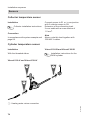
Electronic temperature differential control unit
Vitosolic 200
Type SD4
For applicability, see the last page
VITOSOLIC 200
5414 620 GB
6/2009
Please keep safe.
Safety instructions
Safety instructions
Please follow these safety instructions closely to prevent accidents and material losses.
Danger
This symbol warns against the
risk of injury.
!
Please note
This symbol warns against the
risk of material losses and environmental pollution.
Note
Details identified by the word "Note" contain additional information.
Working on the system
■ Isolate the system from the power supply and check that it is no longer 'live',
e.g. by removing a separate fuse or by
means of a main isolator.
■ Safeguard the system against unauthorised reconnection.
!
Target group
These instructions are exclusively
designed for qualified personnel.
■ Work on electrical equipment must
only be carried out by a qualified electrician.
■ The system must be commissioned by
the system installer or a qualified person authorised by the installer.
Regulations
Observe the following when working on
this system
■ all legal instructions regarding the prevention of accidents,
■ all legal instructions regarding environmental protection,
■ the Code of Practice of relevant trade
associations.
■ all current safety regulations as
defined by DIN, EN, DVGW, VDE and
all locally applicable standards
2
Please note
Electronic modules can be damaged by electrostatic discharges.
Touch earthed objects, such as
heating or water pipes, to discharge static loads.
Repair work
!
Please note
Repairing components that fulfil a
safety function can compromise
the safe operation of your heating
system.
Replace faulty components only
with original Viessmann spare
parts.
5414 620 GB
Safety instructions explained
Safety instructions
Safety instructions (cont.)
Ancillary components, spare and
wearing parts
Please note
Spare and wearing parts that
have not been tested together
with the heating system can compromise its function. Installing
non-authorised components and
non-approved modifications or
conversions can compromise
safety and may invalidate our
warranty.
For replacements, use only original spare parts supplied or
approved by Viessmann.
5414 620 GB
!
3
Index
Index
Installation instructions
System examples
General information..............................................................................................
Overview of system examples..............................................................................
System example 1................................................................................................
System example 2................................................................................................
System example 3................................................................................................
System example 4................................................................................................
System example 5................................................................................................
System example 6................................................................................................
System example 7................................................................................................
System example 8................................................................................................
System example 9................................................................................................
7
8
9
14
21
26
35
41
48
54
59
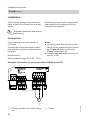
Installation sequence
Fitting the solar control unit..................................................................................
Overview of electrical connections.......................................................................
Pumps..................................................................................................................
High limit safety cut-out........................................................................................
Central fault message facility...............................................................................
Sensors................................................................................................................
Solar cell...............................................................................................................
Power supply........................................................................................................
67
68
69
71
73
74
76
77
Service instructions
79
79
80
81
82
82
82
84
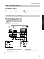
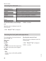
Service scans
Scanning temperatures and operating conditions................................................
Scanning the statement........................................................................................
Scanning the heat yield and temperatures...........................................................
Scanning messages.............................................................................................
85
85
86
87
5414 620 GB
Commissioning
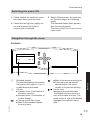
Switching the power ON.......................................................................................
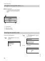
Navigation through the menu...............................................................................
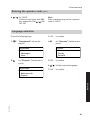
Entering the operator code...................................................................................
Language selection..............................................................................................
Setting the time and date.....................................................................................
Adjusting the display............................................................................................
Setting parameters...............................................................................................
Carrying out a relay test (testing actuators).........................................................
4
Index
Index
Troubleshooting
Fault messages....................................................................................................
Checking sensors.................................................................................................
Checking relays (actuators)..................................................................................
Changing the fuse................................................................................................
88
92
92
93
Function description
Systems................................................................................................................ 94
Function blocks.................................................................................................... 112
Cylinder temperature control................................................................................ 116
Cylinder temperature limit.................................................................................... 117
Cylinder priority control......................................................................................... 117
Collector emergency stop..................................................................................... 118
Bypass.................................................................................................................. 118
External heat exchanger...................................................................................... 122
Cooling function.................................................................................................... 126
Interval function.................................................................................................... 127
Collector cooling function..................................................................................... 128
Reverse cooling function...................................................................................... 129
Frost protection function....................................................................................... 129
Target temperature............................................................................................... 130
Parallel relay......................................................................................................... 130
Booster suppression............................................................................................. 131
Cylinder 2 (to 4) ON............................................................................................. 134
Utilisation of excess heat...................................................................................... 134
Minimum collector temperature limit..................................................................... 135
Cyclical heating.................................................................................................... 135
Additional function for DHW heating.................................................................... 136
Cylinder heating................................................................................................... 138
Speed control....................................................................................................... 139
Central fault message — signalling relay............................................................. 141
Heat statement..................................................................................................... 141
SD module............................................................................................................ 145
Relay kick............................................................................................................. 147
Parts list.............................................................................................................. 148
5414 620 GB
Specification....................................................................................................... 149
Appendix
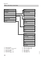
Menu structure overview...................................................................................... 150
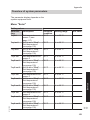
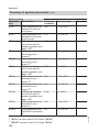
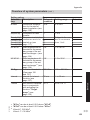
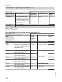
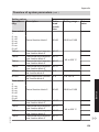
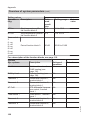
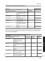
Overview of system parameters........................................................................... 151
PCBs.................................................................................................................... 166
5
Index
Index (cont.)
Certificates
Declaration of conformity...................................................................................... 168
5414 620 GB
Keyword index.................................................................................................... 169
6
System examples
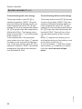
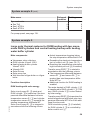
General information
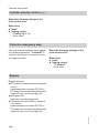
Anti-scalding protection
To limit the temperature to 60 °C,
install mixing equipment, e.g. a
thermostatically controlled mixing valve (accessory). Install a
mixer tap as anti-scalding device
at the draw-off point.
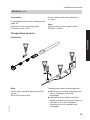
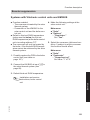
Equipotential bonding and lightning protection of the solar thermal system
Install an electrical conductor on the
pipework system of the solar circuit in the
lower part of the building in compliance
with VDE or local regulations.
The connection of the collector system to
a new or existing lightning protection
system or the provision of local earthing
must only be carried out by authorised
trained personnel, who must take into
account the conditions applicable on
site.
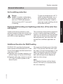
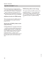
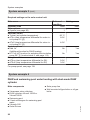
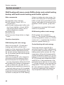
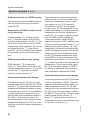
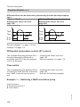
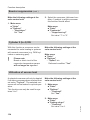
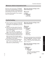
Additional function for DHW heating
We recommend heating up in late afternoon. This ensures that the lower cylinder area or the pre-heating stage is cold
again following the expected drawings
(evenings and the following morning)
and can subsequently be heated up
again by solar energy.
Note
For detached houses and two-family
homes, this heat up is recommended,
but not compulsory.
5414 620 GB
DVGW W 551 specifies that the total
water content is maintained at 60 ºC and
the pre-heat stages must be heated once
every day to 60 ºC.
■ Systems with a cylinder capacity, incl.
preheat stage, in excess of 400 litres
■ Systems with a line content in excess
of 3 l from the DHW cylinder to the
draw-off point
7
Installation
Danger
Subject to system configuration,
DHW temperatures above 60 °C
can occur. DHW with temperatures in excess of 60 °C can result
in scalding.
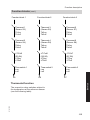
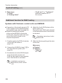
System examples
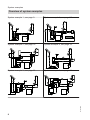
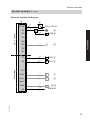
Overview of system examples
System example 1, see page 9.
System example 4, see page 26.
M
M
System example 2, see page 14.
System example 5, see page 35.
M
M
M
M
System example 3, see page 21.
System example 6, see page 41.
M
M
5414 620 GB
M
8
System examples
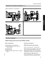
Overview of system examples (cont.)
System example 7, see page 48.
System example 9, see page 59.
M
M
M
Installation
M
System example 8, see page 54.
M
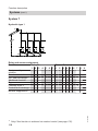
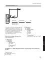
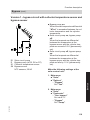
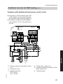
System example 1
5414 620 GB
DHW heating with dual-mode DHW cylinder
Main components
Function description
■ Viessmann solar collectors
■ DHW cylinders Vitocell 100-B or
Vitocell 300-B
■ Vitosolic 200
■ Solar-Divicon
■ Wall mounted oil/gas boiler or oil/gas
boiler
DHW heating with solar energy
Solar circuit pump R1 eE starts and
DHW cylinder qP is heated up if the temperature differential between collector
temperature sensor S1 eQ and cylinder
temperature sensor S2 qQ exceeds the
start temperature differential ΔT.
Solar circuit pump R1 eE is stopped in
accordance with the following criteria:
9
System examples
System example 1 (cont.)
■ Actual temperature dropping below
the stop temperature differential ΔToff
■ Exceeding the electronic temperature
limit of control unit eZ (max. 90 °C)
■ Reaching the temperature selected at
high limit safety cut-out qW (if installed)
Additional function for DHW heating
DHW heating without solar energy
The upper section of DHW cylinder qP is
heated by boiler 1. The cylinder thermostat with cylinder temperature sensor 3 of boiler control unit 2 regulates
circulation pump for cylinder heating
4.
The requirements for the additional function are achieved through circulation
pump R5 qT.
Suppression of DHW cylinder reheating by the boiler
5414 620 GB
Coding address "67" in boiler control unit
2 defaults a third set DHW temperature
(setting range 10 to 95 °C). This value
must be below the first set DHW temperature. DHW cylinder qP will only be
heated by boiler 1 (solar circuit
pump R1 eE runs) if this set value cannot
be achieved by the solar thermal system.
10
System examples
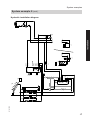
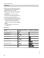
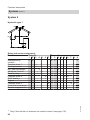
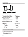
System example 1 (cont.)
qT
eE
eW
5414 620 GB
eQ
qR
P
eP
qW
qP
3
qE
eZ
qQ
2
1
4
2
1
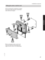
Installation
M
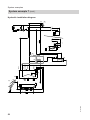
Hydraulic installation diagram
11
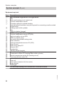
System examples
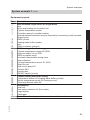
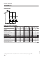
System example 1 (cont.)
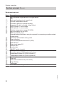
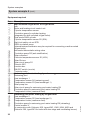
Equipment required
Pos.
1
2
3
4
qP
qQ
qW
qE
qR
qT
eP
eQ
eW
eE
eZ
eU
eI
5414 620 GB
uQ
uW
uE
uR
Description
Wall mounted oil/gas boiler or oil/gas boiler
with
Boiler and heating circuit control unit
Cylinder temperature sensor
Circulation pump for cylinder heating
(integrated for wall mounted oil/gas boiler)
Dual-mode DHW cylinder
Cylinder temperature sensor S2 (SOL)
High limit safety cut-out STB
DHW circulation pump
(internal/external extension may be required for connecting a wall mounted
oil/gas boiler)
Automatic thermostatic mixing valve
Circulation pump R5 (anti-stratification)
Solar collectors
Collector temperature sensor S1 (KOL)
Solar-Divicon
Solar circuit pump R1
Vitosolic 200
Junction box
ON/OFF switch (on site)
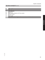
Accessories
Solar cell
Heat meter extension kit (flow meter)
Large display
Datalogger
For boiler and heating circuit accessories, see boiler scheme.
12
System examples
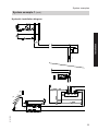
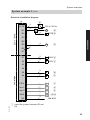
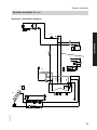
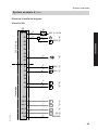
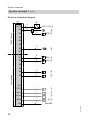
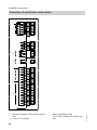
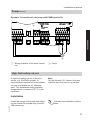
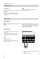
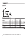
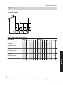
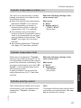
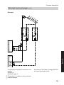
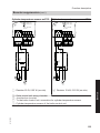
System example 1 (cont.)
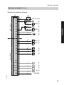
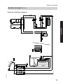
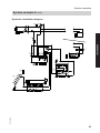
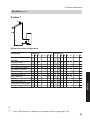
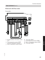
Electrical installation diagram
eZ
N,L,PE
R2
3
eU
3
3
230 V / 50 Hz
M
eE
STB qW
R3
R4
R5
3
M
Installation
230 V / 50 Hz
R1
eI
3
qT
R6
R7
S1
Low voltage
S2
.
.
.
S12
CS10
Imp 1
Imp 2
V BUS
2
2
2
2
2
KOL eQ
SOL qQ
uQ
uW
uE/uR
KM BUS
5414 620 GB
145
2
13
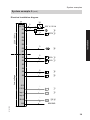
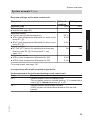
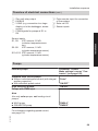
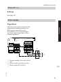
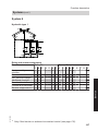
System examples
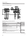
System example 1 (cont.)
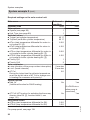
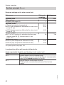
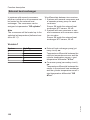
Required settings on the solar control unit
Main menu
Operator code
Solar options
■ System (see page 95)
Set solar values
■ Tcylset (set cylinder temperature)
■ ΔTon (start temperature differential for solar circuit
pump R1 eE)
■ ΔToff (stop temperature differential for solar circuit
pump R1 eE)
System options
■ Add. fct.
(Additional function for DHW heating)
Delivered Setting
condition
0000
1
0200
1
60 °C
8.0 K
4.0 K
No
Yes
(if a DHW circulation pump
is connected)
For pump speed, see page 139.
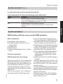
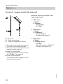
System example 2
Main components
Function description
■ Viessmann solar collectors
■ DHW cylinders Vitocell 100-B or
Vitocell 300-B
■ Heating water buffer cylinder
Vitocell 140-E or Vitocell 160-E
■ Vitosolic 200
■ Solar-Divicon
■ Solar pump line
■ Wall mounted oil/gas boiler or oil/gas
boiler
DHW heating with solar energy
14
Solar circuit pump R1 eE starts and
DHW cylinder qP is heated up if the temperature differential between collector
temperature sensor S1 eQ and cylinder
temperature sensor S2 qQ exceeds the
start temperature differential ΔT.
Solar circuit pump R1 eE is stopped in
accordance with the following criteria:
5414 620 GB
DHW heating with dual-mode DHW cylinder and central heating
backup with heating water buffer cylinder
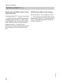
System examples
System example 2 (cont.)
Additional function for DHW heating
The requirements for the additional function are achieved through circulation
pump R5 qT.
Suppression of DHW cylinder reheating by the boiler
Coding address "67" in boiler control
unit 2 defaults a third set DHW temperature (setting range 10 to 95 °C). This
value must be below the first set DHW
temperature. DHW cylinder qP will only
be heated by boiler 1 (solar circuit
pump R1 eE runs) if this set value cannot
be achieved by the solar thermal system.
DHW heating without solar energy
Circulation pump R4 eT is started to heat
heating water buffer cylinder rP if the
DHW cylinder qP cannot be heated and
the temperature differential between collector temperature sensor S1 eQ and
buffer cylinder temperature sensor S4
rQ is greater than start temperature differential ΔT2on. The pump will stop if the
actual temperature falls below the stop
temperature differential ΔT2off or it reaches the set buffer cylinder temperature
Tcyl2set.
The temperature inside heating water
buffer cylinder rP will be limited by the
electronic temperature limiter or high
limit safety cut-out rR (if required).
Circulation pump R4 eT is stopped
roughly every 15 min for approx. 2 min,
(times adjustable), to check whether the
temperature at collector temperature
sensor S1 eQ is high enough to change
over to DHW cylinder heating qP.
Three-way diverter valve R6 rZ is
switched to position "AB-A" and the heating return water is routed to boiler 1 via
heating water buffer cylinder rP, if the
temperature differential between buffer
cylinder temperature sensor S5 rE and
heating circuit return temperature sensor S6 rT exceeds start temperature differential ΔT6on. If the temperature of the
preheated return water is too low, boiler
1 reheats the water to the required flow
temperature. Three-way diverter valve
R6 rZ is switched to position "AB-B" if
the actual temperature falls below the
stop temperature differential ΔT6off.
5414 620 GB
The upper section of DHW cylinder qP is
heated by boiler 1. The cylinder thermostat with cylinder temperature sensor 3 of boiler control unit 2 regulates
circulation pump for cylinder heating 4.
Central heating with solar energy
15
Installation
■ Actual temperature dropping below
the stop temperature differential ΔToff
■ Exceeding the electronic temperature
limit of control unit eZ (max. 90 °C)
■ Reaching the temperature selected at
high limit safety cut-out qW (if installed)
System examples
System example 2 (cont.)
Central heating without solar energy
5414 620 GB
Three-way diverter valve R6 rZ remains
at zero volt (position "AB-B") if the temperature differential between buffer cylinder temperature sensor S5 rE and
heating circuit return temperature sensor
S6 rT is less than temperature differential ΔT6off. There will be no flow through
heating water buffer cylinder rP.
Boiler 1 supplies the heating circuit
with heat according to the heating curve
set at boiler control unit 2.
A low loss header 6 with flow temperature sensor 5 is required in conjunction with a wall mounted oil/gas
boiler.
16
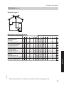
5414 620 GB
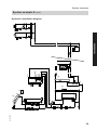
eW
eE
eR
eT
eQ
qT
qR
P
qP
qW
eP
qQ
3
qE
eZ
rQ
rR
rE
rP
2
1
4
HR3
HR4
HV3/HR1
HR2
HV1
HV2
6
5
1
Installation
2
rZ
BM A
AB
rT
M
System examples
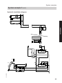
System example 2 (cont.)
Hydraulic installation diagram
17
System examples
System example 2 (cont.)
Equipment required
Pos.
1
2
3
4
qP
qQ
qW
qE
qR
qT
eP
eQ
eW
eE
eZ
eU
eI
rP
eR
eT
rQ
rE
rR
rT
rZ
5414 620 GB
uQ
uW
uE
uR
Description
Wall mounted oil/gas boiler or oil/gas boiler
with
Boiler and heating circuit control unit
Cylinder temperature sensor
Circulation pump for cylinder heating
(internal/external extension may be required for connecting a wall mounted
oil/gas boiler)
DHW heating with solar energy
Dual-mode DHW cylinder
Cylinder temperature sensor S2 (SOL)
High limit safety cut-out STB
DHW circulation pump
Automatic thermostatic mixing valve
Circulation pump R5 (anti-stratification)
Solar collectors
Collector temperature sensor S1 (KOL)
Solar-Divicon
Solar circuit pump R1
Vitosolic 200
Junction box
ON/OFF switch (on site)
Central heating with solar energy
Heating water buffer cylinder
Solar pump line
Solar circuit pump for heating buffer cylinder R4
Temperature sensor S4 (heating water buffer cylinder), heating up
Temperature sensor S5 (heating water buffer cylinder), discharge
High limit safety cut-out STB
Return temperature sensor S6 (heating circuit)
Three-way diverter valve R6
Accessories
Solar cell
Heat meter extension kit (flow meter)
Large display
Datalogger
For boiler and heating circuit accessories, see boiler scheme.
18
System examples
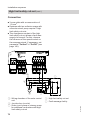
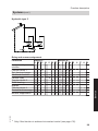
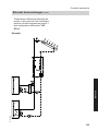
System example 2 (cont.)
Electrical installation diagram
eZ
230 V / 50 Hz
R1
R2
R3
R4
R5
R6
3
eU
3
3
eU
3
3
3
3
230 V / 50 Hz
M
eE
STB qW
M
eT
STB rR
M
qT
M
rZ
Installation
N,L,PE
eI
3
R7
S1
S2
S3
S4
Low voltage
S5
S6
.
.
.
S12
CS10
Imp 1
Imp 2
V BUS
2
2
2
2
2
2
2
2
2
KOL eQ
SOL qQ
rQ
rE
rT
uQ
uW
uW
uE/uR
KM BUS
5414 620 GB
145
2
19
System examples
System example 2 (cont.)
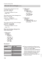
Required settings on the solar control unit
Operator code
Solar options
■ System (see page 99)
■ Hyd. Type (see page 99)
Set solar values
■ Tcylset (set cylinder temperature)
■ Tcyl2set (set buffer cylinder temperature)
■ ΔTon (start temperature differential for solar circuit pump R1 eE)
■ ΔToff (stop temperature differential for solar circuit pump R1 eE)
■ ΔT2on (start temperature differential for solar circuit pump for buffer cylinder heating R4 eT)
■ ΔT2off (stop temperature differential for solar circuit pump for buffer cylinder heating R4 eT)
■ Priority Cyl1
■ Priority Cyl2
Solar contractor
■ t-stop (duration of the pump runtime interruption)
■ t-circ. (break intervals)
■ ΔT Col
During the t-stop time the collector temperature
must rise by the value of ΔT Col to change over
to heating the consumer with priority 1.
System options
■ Add. fct.
(Additional function for DHW heating)
■ ΔT Fct6 (ΔT function for switching the three-way
diverter valve R6 rZ, function block 2, see
page 112)
Set system values
■ ΔT6on (start temperature differential for R6)
■ ΔT6off (stop temperature differential for R6)
For pump speed, see page 139.
20
Delivered
Setting
condition
0000
1
1
0200
3
2
60 °C
60 °C
8.0 K
4.0 K
8.0 K
4.0 K
1
2
2 minutes
15 minutes
2K
No
Yes
(if a DHW circulation pump is
connected)
No
Yes
5.0 K
3.0 K
5414 620 GB
Main menu
System examples
System example 2 (cont.)
In conjunction with a wall mounted oil/gas boiler
Installation
Codes required at the boiler and heating circuit control unit
Code
Function
53:3
System without DHW circulation pump:
The circulation pump for cylinder heating 4 is connected to
output sK of internal extension H1 or H2
5b:1
Internal diverter valve without function
(DHW cylinder connected downstream of the low loss
header)
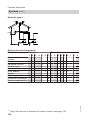
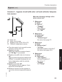
System example 3
DHW heating with two mono-mode DHW cylinders
Main components
■ Viessmann solar collectors
■ 2 DHW cylinders Vitocell 100-V or
Vitocell 300-V
■ Vitosolic 200
■ Solar-Divicon
■ Wall mounted oil/gas boiler or oil/gas
boiler
Function description
DHW heating with solar energy
5414 620 GB
Solar circuit pump R1 eE is switched on
and DHW cylinder 1 qP is heated up if
the temperature differential between collector temperature sensor S1 eQ and
cylinder temperature sensor S2 qQ is
greater than the start temperature differential ΔTon.
Solar circuit pump R1 eE is stopped in
accordance with the following criteria:
■ Actual temperature dropping below
the stop temperature differential ΔToff
■ Exceeding the electronic temperature
limit of control unit eZ (max. 90 °C)
■ Reaching the temperature selected at
high limit safety cut-out qW (if installed)
Transfer pump R5/R6 qT is started in
accordance with the following criteria:
■ The temperature differential between
sensor S5 qZ and sensor S6 qU is
greater than start temperature differential ΔT6on
■ Additional function for DHW heating is
enabled
The water heated in DHW cylinder 1 qP
is transferred to DHW cylinder 2 qI. This
way, DHW cylinder 2 qI is also heated
by solar energy.
Transfer pump R5/R6 qT stops when the
actual temperature falls below stop temperature differential ΔT6off or if the additional function stops.
DHW circulation pump qE (if installed)
for DHW cylinder 2 qI is controlled by
boiler control unit 2.
21
System examples
System example 3 (cont.)
Suppression of DHW cylinder reheating by the boiler
DHW cylinder 2 qI is heated by boiler
1. The cylinder thermostat with cylinder
temperature sensor 3 of boiler control
unit 2 regulates circulation pump for
cylinder heating 4.
5414 620 GB
Coding address "67" in boiler control unit
2 defaults a third set DHW temperature
(setting range 10 to 95 °C). This value
must be below the first set DHW temperature. DHW cylinder 2 qI will only be
heated by boiler 1 (solar circuit
pump R1 eE runs) if this set value cannot
be achieved by the solar thermal system.
DHW heating without solar energy
22
System examples
System example 3 (cont.)
qU
eE
eW
5414 620 GB
eQ
qW
P
1
qP
qQ
eP
qT
qZ
eZ
qR
2
qI
qE
3
2
1
4
2
Installation
1
M
Hydraulic installation diagram
23
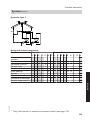
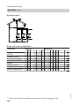
System examples
System example 3 (cont.)
Equipment required
Pos.
1
2
3
4
qI
qP
qQ
qW
qE
qR
eP
eQ
eW
eE
eZ
eU
eI
qT
qZ
qU
5414 620 GB
uQ
uW
uE
uR
Description
Wall mounted oil/gas boiler or oil/gas boiler
with
Boiler and heating circuit control unit
Cylinder temperature sensor
Circulation pump for cylinder heating
(integrated for wall mounted oil/gas boiler)
DHW cylinder 2, mono-mode
DHW cylinder 1, mono-mode
Cylinder temperature sensor S2 (SOL)
High limit safety cut-out STB
DHW circulation pump
(internal/external extension may be required for connecting a wall mounted
oil/gas boiler)
Automatic thermostatic mixing valve
Solar collectors
Collector temperature sensor S1 (KOL)
Solar-Divicon
Solar circuit pump R1
Vitosolic 200
Junction box
ON/OFF switch (on site)
DHW circulation diversion
Circulation pump R5/R6 (anti-stratification)
Temperature sensor S5 (DHW cylinder 1)
Temperature sensor S6 (DHW cylinder 2)
Accessories
Solar cell
Heat meter extension kit (flow meter)
Large display
Datalogger
For boiler and heating circuit accessories, see boiler scheme.
24
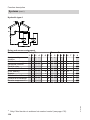
System examples
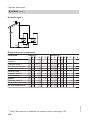
System example 3 (cont.)
Electrical installation diagram
eZ
N,L,PE
3
eU
3
3
R2
230 V / 50 Hz
M
eE
STB qW
R3
R4
3
R5
R6
M
Installation
230 V / 50 Hz
R1
eI
3
qT
A
R7
S1
S2
2
2
KOL eQ
SOL qQ
S3
S4
Low voltage
S5
S6
.
.
.
CS10
Imp 1
Imp 2
V BUS
5414 620 GB
145
2
2
2
2
2
2
2
qZ
qU
uQ
uW
uW
uE/uR
KM BUS
A Insert the jumper between R5 and
R6.
25
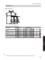
System examples
System example 3 (cont.)
Required settings on the solar control unit
Main menu
Operator code
Solar options
■ System (see page 95)
Set solar values
■ Tcylset (set cylinder temperature)
■ ΔTon (start temperature differential for solar circuit pump R1 eE)
■ ΔToff (stop temperature differential for solar circuit pump R1 eE)
System options
■ Add. fct.
(Additional function for DHW heating)
■ ΔT Fct6 (ΔT function for switching the circulation
pump R6 qT, function block 2, see page 112)
Set system values
■ ΔT6on (start temperature differential for R6)
■ ΔT6off (stop temperature differential for R6)
Delivered
Setting
condition
0000
0200
1
1
60 °C
8.0 K
4.0 K
No
Yes
No
Yes
5.0 K
3.0 K
For pump speed, see page 139.
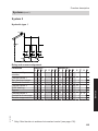
System example 4
DHW and swimming pool water heating with dual-mode DHW
cylinder
■ Viessmann solar collectors
■ DHW cylinders Vitocell 100-B or
Vitocell 300-B
■ Swimming pool
■ 2 heat exchangers for swimming pool
water
■ Vitosolic 200
■ Solar-Divicon
26
■ Solar pump line
■ Wall mounted oil/gas boiler or oil/gas
boiler
5414 620 GB
Main components
System examples
Function description
DHW heating without solar energy
DHW heating with solar energy
The upper section of DHW cylinder qP
is heated by boiler 1. The cylinder thermostat with cylinder temperature sensor 3 of boiler control unit 2 regulates
circulation pump for cylinder heating 4.
Solar circuit pump R1 eE starts and
DHW cylinder qP is heated up if the temperature differential between collector
temperature sensor S1 eQ and cylinder
temperature sensor S2 qQ is greater
than the start temperature differential
ΔTon.
Solar circuit pump R1 eE is stopped in
accordance with the following criteria:
■ Actual temperature dropping below
the stop temperature differential ΔToff
■ Exceeding the electronic temperature
limit of control unit eZ (max. 90 °C)
■ Reaching the temperature selected at
high limit safety cut-out qW (if installed)
Additional function for DHW heating
The requirements for the additional function are achieved through circulation
pump R5 qT.
Suppression of DHW cylinder reheating by the boiler
5414 620 GB
Coding address "67" in boiler control
unit 2 defaults a third set DHW temperature (setting range 10 to 95 °C). This
value must be below the first set DHW
temperature. DHW cylinder qP will only
be heated by boiler 1 (solar circuit
pump R1 eE runs) if this set value cannot
be achieved by the solar thermal system.
Swimming pool water heating by
solar energy
If the DHW cylinder qP cannot continue
to be heated, the system checks whether
the swimming pool tP can be heated.
Circulation pump R4 eT starts if the temperature differential between collector
temperature sensor S1 eQ and temperature sensor S4 tW is greater than start
temperature differential ΔT2on. The
pump stops if the actual temperature
falls below the stop temperature differential ΔT2off or if the set swimming pool
temperature Tcyl2set has been
reached.
Circulation pump R4 eT is stopped
roughly every 30 minutes for approx.
7 minutes (times adjustable), to check
whether the temperature at collector
temperature sensor S1 eQ is high
enough to change over to DHW cylinder
heating qP.
The circulation pump for heating swimming pool water R3 tE starts if the temperature differential between temperature sensor S3 tT and temperature sensor S4 tW is greater than start temperature differential ΔT5on and start temperature differential Th2on has not been
reached. The pump stops if the actual
temperature falls below the stop temperature differential ΔT5off or if the stop
temperature Th2off has been reached.
27
Installation
System example 4 (cont.)
System examples
System example 4 (cont.)
Filter time and possible reheating by the
boiler 1:
■ outside the times during which heating
by solar energy can be expected
■ outside the times when central heating
and DHW heating are required
5414 620 GB
Swimming pool water heating by
boiler:
If the solar energy is inadequate to heat
the swimming pool water, it will be
heated by boiler 1 via temperature sensor S5 tU on heat exchanger 2 tZ.
Circulation pump R6 zP and filter
pump tI start when the start temperature Th3on and has not been reached
during the time set via time switch 2. The
pumps stop when the stop temperature
Th3off has been reached or if the time
frame is exceeded.
28
5414 620 GB
eT
eR eW
eE
eQ
qT
qR
P
qP
qW
eP
qQ
3
qE
eZ
2
1
4
2
Installation
1
tE
tI
tW
tR
tU
tO
tP
M
tQ
tZ
tT
zP
System examples
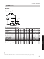
System example 4 (cont.)
Hydraulic installation diagram
29
System examples
System example 4 (cont.)
Pos.
1
2
3
4
qP
qQ
qW
qE
qR
qT
eP
eQ
eW
eE
eZ
eU
eI
eO
tP
tQ
tW
tT
eR
eT
tE
tR
tZ
tU
tO
zP
zQ
30
Description
Wall mounted oil/gas boiler or oil/gas boiler
with
Boiler and heating circuit control unit
Cylinder temperature sensor
Circulation pump for cylinder heating
(integrated for wall mounted oil/gas boiler)
Dual-mode DHW cylinder
Cylinder temperature sensor S2 (SOL)
High limit safety cut-out STB
DHW circulation pump
(internal/external extension may be required for connecting a wall mounted
oil/gas boiler)
Automatic thermostatic mixing valve
Circulation pump R5 (anti-stratification)
Solar collectors
Collector temperature sensor S1 (KOL)
Solar-Divicon
Solar circuit pump R1
Vitosolic 200
Junction box
ON/OFF switch (on site)
Contactor relay
Swimming pool water heating by solar energy
Swimming pool
Heat exchanger 1
Temperature sensor S4 (swimming pool)
Temperature sensor S3 (heat exchanger 1)
Solar pump line
Solar circuit pump for swimming pool water heating R4
Circulation pump for swimming pool water heating R3
Temperature limiter (maximum limit)
Swimming pool water heating by oil/gas boiler
Heat exchanger 2
Temperature sensor S5 (heat exchanger 2)
Temperature limiter (maximum limit)
Circulation pump for swimming pool water heating R6 (reheating)
Control module V
(in conjunction with Vitotronic 200, types KW1, KW2, KW4, KW5 and
Vitotronic 300, type KW3 for boiler with two-stage and modulating burner)
5414 620 GB
Equipment required
System examples
System example 4 (cont.)
Pos.
tI
5414 620 GB
Installation
uQ
uW
uE
uR
Description
Filter pump
Accessories
Solar cell
Heat meter extension kit (flow meter)
Large display
Datalogger
For boiler and heating circuit accessories, see boiler scheme.
31
System examples
System example 4 (cont.)
Electrical installation diagram
eI
230 V / 50 Hz
eZ
L 35
N
?
M
1~
230 V / 50 Hz
R134
R233
eE
qW
R332
R431
M
1~
R530
N
eT
tR
?
R629
R7-R
R7-M
R7-A
S1
S2
S3
Low voltage
S4
S5
S6
.
.
.
CS10
Imp 1
Imp 2
V BUS
145
M
1~
2
2
2
SOL qQ
tE
tO
tT
tW
2
tU
eO
2
uQ
2
uW
2
2
M
1~
KOL eQ
2
2
eO
qT
M
1~
uW
AB
uE/uR
KM BUS
zP
eU
5414 620 GB
A, B See the following page.
32
System examples
A Start signal for filter pump tI
B External burner start in conjunction
with the following control units:
Vitotronic 200, types KW1, KW2, KW4,
KW5, Vitotronic 300, type KW3:
Connection in plug "X12"
or
Connection in plug aBÖ at terminals
"ON", "ON/TR"
or
in socket "DE4" in control module V zQ
in plug a-D at terminals "1" and "2"
(Set the minimum set boiler water temperature via coding address "32" at the
boiler circuit control unit)
Vitotronic 200, type GW1, GW2:
Connection in plug aVH at terminals "2"
and "3"
(Set the minimum set boiler water temperature via coding address "9b" at the
boiler circuit control unit)
Vitotronic 200, type KW6:
Connection in plug aVD at terminals "1"
and "2"
(Set the minimum set boiler water temperature via coding address "9b" at the
boiler circuit control unit)
Vitotronic 200, type HO1/HO1A:
Connection in external extension H1, in
plug aVD at terminals "1" and "2"
(Set the minimum set boiler water temperature via coding address "9b" at the
boiler circuit control unit)
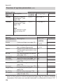
Required settings on the solar control unit
5414 620 GB
Main menu
Operator code
Solar options
■ System (see page 99)
■ Hyd. Type (see page 99)
Set solar values
■ Tcylset (set cylinder temperature)
■ Tcyl2set (set swimming pool temperature)
■ ΔTon (start temperature differential for solar circuit pump R1 eE)
■ ΔToff (stop temperature differential for solar circuit pump R1 eE)
■ ΔT2on (start temperature differential for solar circuit pump for swimming pool water heating R4
eT)
■ ΔT2off (stop temperature differential for solar circuit pump for swimming pool water heating R4
eT)
■ Priority Cyl1
■ Priority Cyl2 (swimming pool)
Delivered
Setting
condition
0000
0200
1
1
3
2
60 °C
60 °C
8.0 K
28 °C
4.0 K
8.0 K
4.0 K
1
2
33
Installation
System example 4 (cont.)
System examples
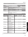
System example 4 (cont.)
Main menu
Delivered
condition
Solar contractor
■ t-stop (duration of the pump runtime interruption)
■ t-circ. (break intervals)
■ ΔT Col
During the t-stop time the collector temperature
must rise by the value of ΔT Col to change over
to heating the consumer with priority 1.
System options
■ Add. fct.
(Additional function for DHW heating)
■ Thermost. 2 (S4)
(Thermostat function for maximum temperature
stop of circulation pump R3 tE, function block 1,
see page 112)
■ ΔT Fct5 (ΔT function for switching the circulation
pump R3 tE, function block 1, see page 112)
■ Thermost. 3 (S5)
(Thermostat function for swimming pool water
heating by the boiler,
for switching circulation pump R6 zP, function
block 2, see page 112)
■ Time switch 2*1
Set system values
■ Th2on (start temperature for R3)
■ Th2off (stop temperature for R3)
■ ΔT5on (start temperature differential for R3)
■ ΔT5off (stop temperature differential for R3)
■ Th3on (start temperature for R6 and tI)
■ Th3off (stop temperature for R6 and tI)
*1
*2
2 minutes
15 minutes
2K
7 minutes
30 minutes
No
Yes
(if a DHW circulation pump is
connected)
No
Yes
No
Yes
No
Yes
No
Yes
40 °C Tcyl2set−0.5 K
45 °C
Tcylset*2
5.0 K
3.0 K
40 °C
26.5 °C
45 °C
Th3on + 0.5 K
For the solar circuit pump for swimming
pool water heating R4 eT, parameter
"Control" must not be set to "Pulse"
(see page 140).
Setting the times, see page 159.
Possibly set a value 1 to 2 K higher. For this, observe that the relative humidity will
increase in indoor swimming pools.
34
5414 620 GB
For pump speed, see page 139.
Setting
System examples
System example 5
DHW heating and central heating backup with a multi-mode heating water buffer cylinder
■ Viessmann solar collectors
■ Vitocell 340-M or Vitocell 360-M multimode heating water buffer cylinder
with integral DHW heating, with or
without stratification system
■ Vitosolic 200
■ Solar-Divicon
■ Wall mounted oil/gas boiler or oil/gas
boiler
Function description
5414 620 GB
DHW heating with solar energy
Solar circuit pump R1 eE starts and
heating water buffer cylinder qP is
heated up if the temperature differential
between collector temperature sensor
S1 eQ and cylinder temperature sensor
S2 qQ is greater than the start temperature differential ΔTon.
Solar circuit pump R1 eE is stopped in
accordance with the following criteria:
■ Actual temperature dropping below
the stop temperature differential ΔToff
■ Exceeding the electronic temperature
limit of control unit eZ (max. 90 °C)
■ Reaching the temperature selected at
high limit safety cut-out qW (if installed)
Entire heating water buffer cylinder qP is
heated by the solar thermal system if the
insolation is adequate.
The upper part of heating water buffer
cylinder qP will only be reheated by
boiler 1 if the actual water temperature
falls below the set temperature selected
at boiler control unit 2.
If the solar energy is inadequate to cover
the entire heat demand, the DHW in the
lower part of heating water buffer cylinder qP will be preheated by solar energy.
The DHW in the upper part of the cylinder is heated to the required temperature
by boiler 1.
Suppression of DHW cylinder reheating by the boiler
Coding address "67" in boiler control
unit 2 defaults a third set DHW temperature (setting range 10 to 95 °C). This
value must be below the first set DHW
temperature. The DHW cylinder will only
be heated by the boiler (solar circuit
pump R1 eE runs) if this set value cannot
be achieved by the solar thermal system.
DHW heating without solar energy
The upper area of heating water buffer
cylinder qP is heated by boiler 1. The
integral instantaneous water heater/
standby section is heated by the surrounding buffer cylinder water.
The cylinder thermostat with cylinder
temperature sensor 3 of boiler control
unit 2 regulates circulation pump for
cylinder heating 4.
35
Installation
Main components
System examples
System example 5 (cont.)
Central heating without solar energy
Three-way diverter valve R6 rZ is
switched to position "AB-A" if the temperature differential between buffer cylinder temperature sensor S5 qZ and
heating circuit return temperature sensor
S6 rT is greater than start temperature
differential ΔT6on. The heating return
water is fed to boiler 1 via heating water
buffer cylinder qP.
If the temperature of the preheated
return water is too low, boiler 1 reheats
the water to the required flow temperature. Three-way diverter valve R6 rZ is
switched to position "AB-B" if the actual
temperature falls below stop temperature differential ΔT6off.
Three-way diverter valve R6 rZ remains
at zero volt (position "AB-B") if the temperature differential between buffer cylinder temperature sensor S5 qZ and
heating circuit return temperature sensor
S6 rT is less than stop temperature differential ΔT6off. There will be no flow
through heating water buffer cylinder
qP.
Boiler 1 supplies the heating circuit
with heat according to the heating curve
set at boiler control unit 2.
A low loss header 6 with flow temperature sensor 5 is required in conjunction with a wall mounted oil/gas
boiler.
5414 620 GB
Central heating with solar energy
36
5414 620 GB
eE
eW
eQ
qW
3
qQ
qZ
P
eP
qP
eZ
HR3
HR2
HV2/HR1
wW
HV1
qR
2
qE
1
6
5
1
Installation
2
4
B M A
rZ AB
rT
M
System examples
System example 5 (cont.)
Hydraulic installation diagram
37
System examples
System example 5 (cont.)
Equipment required
Pos.
1
2
3
4
qP
wW
qQ
qW
qE
qR
eP
eQ
eW
eE
eZ
eU
eI
qZ
rT
rZ
5414 620 GB
uQ
uW
uE
uR
Description
Wall mounted oil/gas boiler or oil/gas boiler
with
Boiler and heating circuit control unit
Cylinder temperature sensor
Circulation pump for cylinder heating
(internal/external extension may be required for connecting a wall mounted
oil/gas boiler)
Heating water buffer cylinder
with
DHW circulation (integral)
DHW heating with solar energy
Cylinder temperature sensor S2 (SOL)
High limit safety cut-out STB
DHW circulation pump
Automatic thermostatic mixing valve
Solar collectors
Collector temperature sensor S1 (KOL)
Solar-Divicon
Solar circuit pump R1
Vitosolic 200
Junction box
ON/OFF switch (on site)
Central heating with solar energy
Temperature sensor S5 (heating water buffer cylinder)
Return temperature sensor S6 (heating circuit)
Three-way diverter valve R6
Accessories
Solar cell
Heat meter extension kit (flow meter)
Large display
Datalogger
For boiler and heating circuit accessories, see boiler scheme.
38
System examples
System example 5 (cont.)
Electrical installation diagram
eZ
N,L,PE
R2
3
eU
3
3
230 V / 50 Hz
M
eE
STB qW
R3
R4
R5
R6
3
M
Installation
230 V / 50 Hz
R1
eI
3
rZ
R7
S1
S2
2
2
KOL eQ
SOL qQ
S3
S4
Low voltage
S5
S6
.
.
.
S12
CS10
Imp 1
Imp 2
V BUS
2
2
2
2
2
qZ
rT
uQ
uW
uE/uR
KM BUS
5414 620 GB
145
2
39
System examples
System example 5 (cont.)
Required settings on the solar control unit
Main menu
Operator code
Solar options
■ System (see page 95)
Set solar values
■ Tcylset (set cylinder temperature)
■ ΔTon (start temperature differential for solar circuit
pump R1 eE)
■ ΔToff (stop temperature differential for solar circuit
pump R1 eE)
System options
■ ΔT Fct6 (ΔT function for switching the three-way
diverter valve R6 rZ, function block 2, see
page 112)
Set system values
■ ΔT6on (start temperature differential for R6)
■ ΔT6off (stop temperature differential for R6)
Delivered
Setting
condition
0000
0200
1
1
60 °C
8.0 K
4.0 K
No
Yes
5.0 K
3.0 K
For pump speed, see page 139.
In conjunction with a wall mounted oil/gas boiler
5414 620 GB
Codes required at the boiler and heating circuit control unit
Code
Function
53:3
System without DHW circulation pump:
The circulation pump for cylinder heating 4 is connected to
output sK of internal extension H1 or H2
5b:1
Internal diverter valve without function
(DHW cylinder connected downstream of the low loss
header)
40
System examples
System example 6
Main components
DHW heating with solar energy
■ Viessmann solar collectors
■ Freshwater module
■ Heating water buffer cylinder
Vitocell 140-E or Vitocell 160-E
■ Vitosolic 200
■ Solar-Divicon
■ Wall mounted oil/gas boiler or oil/gas
boiler
Solar circuit pump R1 eE starts and
heating water buffer cylinder rP is
heated up if the temperature differential
between collector temperature sensor
S1 eQ and cylinder temperature sensor
S2 rQ is greater than the start temperature differential ΔTon.
Solar circuit pump R1 eE is stopped in
accordance with the following criteria:
■ Actual temperature dropping below
the stop temperature differential ΔToff
■ Exceeding the electronic temperature
limit of control unit eZ (max. 90 °C)
■ Reaching the temperature selected at
high limit safety cut-out rR (if installed)
Entire heating water buffer cylinder rP is
heated by the solar thermal system if the
insolation is adequate.
The upper part of heating water buffer
cylinder rP will only be reheated by
boiler 1 if the actual water temperature
falls below the set temperature selected
at boiler control unit 2.
5414 620 GB
Function description
Freshwater module qP heats DHW
when hot water is drawn. The energy
supply to freshwater module qP is provided via heating water buffer cylinder rP. Buffer cylinder rP is heated by
the solar thermal system or, in the upper
area, by boiler 1.
The heated DHW is heated by freshwater module qP according to the instantaneous water heater principle. An internal
pump transports the heating water from
heating water buffer cylinder rP into the
freshwater module qP. This heats the
DHW in the heat exchanger of the freshwater module qP according to the countercurrent principle. This is regulated by
the internal control unit of the freshwater
module qP.
When utilising the freshwater module
with integral DHW circulation pump, the
three-way diverter valve qQ in conjunction with sensors qE and S4 qW of the
freshwater module can be regulated by
its control unit to provide an optimum
stratification of the return water into the
heating water buffer cylinder rP.
DHW heating without solar energy
The upper area of heating water buffer
cylinder rP is heated by boiler 1. The
cylinder thermostat with cylinder temperature sensor 3 of boiler control unit
2 regulates circulation pump for cylinder heating 4.
41
Installation
DHW heating with freshwater module and central heating backup
with heating water buffer cylinder
System examples
System example 6 (cont.)
Central heating without solar energy
Three-way diverter valve R6 rZ is
switched to position "AB-A" and the heating return water is routed to boiler 1 via
heating water buffer cylinder rP, if the
temperature differential between buffer
cylinder temperature sensor S5 rW and
heating circuit return temperature sensor
S6 rT exceeds start temperature differential ΔT6on. If the temperature of the
preheated return water is too low,
boiler 1 reheats the water to the
required flow temperature. Three-way
diverter valve R6 rZ is switched to position "AB-B" if the actual temperature falls
below the stop temperature differential
ΔT6off.
Three-way diverter valve R6 rZ remains
at zero volt (position "AB-B") if the temperature differential between buffer cylinder temperature sensor S5 rW and
heating circuit return temperature sensor
S6 rT is less than temperature differential ΔT6off. There will be no flow through
heating water buffer cylinder rP.
Boiler 1 supplies the heating circuit
with heat according to the heating curve
set at boiler control unit 2.
A low loss header 6 with flow temperature sensor 5 is required in conjunction with a wall mounted oil/gas
boiler.
5414 620 GB
Central heating with solar energy
42
5414 620 GB
eE
eW
eQ
P
qW
eP
qP
eZ
rQ
qE
rW
3
rR
2
rP
B M A
6
5
qQ AB
Installation
1
HR3
HR4
HV3/HR1
HR2
HV2
HV1
2
4
1
M
rZ
B MA
AB
rT
System examples
System example 6 (cont.)
Hydraulic installation diagram
43
System examples
System example 6 (cont.)
Equipment required
Pos.
1
2
3
4
qP
qQ
qW
qE
rP
rQ
rR
eP
eQ
eW
eE
eZ
eU
eI
rW
rT
rZ
5414 620 GB
uQ
uW
uE
uR
Description
Wall mounted oil/gas boiler or oil/gas boiler
with
Boiler and heating circuit control unit
Cylinder temperature sensor
Circulation pump for cylinder heating
(internal/external extension may be required for connecting a wall mounted
oil/gas boiler)
Freshwater module
Three-way diverter valve (accessory for pos. qP)
Temperature sensor S4 (accessory for pos. qP)
Temperature sensor S3 (accessory for pos. qP)
Heating water buffer cylinder
DHW heating with solar energy
Cylinder temperature sensor S2 (SOL)
High limit safety cut-out STB
Solar collectors
Collector temperature sensor S1 (KOL)
Solar-Divicon
Solar circuit pump R1
Vitosolic 200
Junction box
ON/OFF switch (on site)
Central heating with solar energy
Temperature sensor S5 (heating water buffer cylinder)
Return temperature sensor S6 (heating circuit)
Three-way diverter valve R6
Accessories
Solar cell
Heat meter extension kit (flow meter)
Large display
Datalogger
For boiler and heating circuit accessories, see boiler scheme.
44
System examples
System example 6 (cont.)
Electrical installation diagram
Vitosolic 200
eZ
230 V / 50 Hz
R1
R2
3
eU
230 V / 50 Hz
3
3
M
eE
STB rR
Installation
N,L,PE
eI
3
R3
R4
R5
R6
3
M
rZ
R7
S1
S2
2
2
KOL eQ
SOL rQ
S3
S4
Low voltage
S5
S6
.
.
.
S12
CS10
Imp 1
Imp 2
5414 620 GB
V BUS
145
2
2
2
2
2
2
2
rW
rT
uQ
uW
uW
uE/uR
KM BUS
45
System examples
System example 6 (cont.)
R4
R3
R2
R1
R5-A
R5-M
R5-R
GND
S1
S2
S3
S4
S5
S6
S7
Control unit, freshwater module
L N
N
?
qP
M
1~
qE
qW
qQ
?N L
230 V / 50 Hz
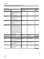
Required settings on the solar control unit
Main menu
1
1
60 °C
8.0 K
4.0 K
No
Yes
5414 620 GB
Operator code
Solar options
■ System (see page 95)
Set solar values
■ Tcylset (set cylinder temperature)
■ ΔTon (start temperature differential for solar circuit
pump R1 eE)
■ ΔToff (stop temperature differential for solar circuit
pump R1 eE)
System options
■ ΔT Fct6 (ΔT function for switching the three-way
diverter valve R6 rZ, function block 2, see
page 112)
Delivered
Setting
condition
0000
0200
46
System examples
System example 6 (cont.)
Main menu
Delivered
condition
Set system values
■ ΔT6on (start temperature differential for R6)
■ ΔT6off (stop temperature differential for R6)
Setting
5.0 K
3.0 K
For pump speed, see page 139.
Main menu
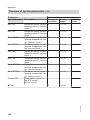
Options
■ Return dist. (return distribution)
Setting values
■ ΔT-RVon (start temperature differential for return
valve R3 qQ)
■ ΔT-RVoff (stop temperature differential for return
valve R3 qQ)
Delivered
condition
OFF
Setting
ON
5.0 K
5.0 K
In conjunction with a wall mounted oil/gas boiler
5414 620 GB
Codes required at the boiler and heating circuit control unit
Code
Function
53:3
System without DHW circulation pump:
The circulation pump for cylinder heating 4 is connected to
output sK of internal extension H1 or H2
5b:1
Internal diverter valve without function
(DHW cylinder connected downstream of the low loss
header)
47
Installation
Required settings at the freshwater module control unit
System examples
System example 7
DHW heating with mono-mode DHW cylinder and central heating
backup with multi-mode heating water buffer cylinder
Main components
■ Viessmann solar collectors
■ DHW cylinder Vitocell 100-V or
Vitocell 300-V
■ Multi-mode heating water buffer cylinder Vitocell 340-M or Vitocell 360-M
with integral DHW heating, with or
without stratification system
■ Vitosolic 200
■ Solar-Divicon
■ Wall mounted oil/gas boiler or oil/gas
boiler
Function description
DHW heating with solar energy
DHW heating without solar energy
DHW cylinder qP is heated by
boiler 1. The cylinder thermostat with
cylinder temperature sensor 3 of boiler
control unit 2 regulates the circulation
pump for cylinder heating 4.
Central heating with solar energy
Three-way diverter valve R6 rZ is
switched to position "AB-A" and the heating return water is routed to boiler 1 via
heating water buffer cylinder rP, if the
temperature differential between buffer
cylinder temperature sensor S5 rW and
heating circuit return temperature sensor
S6 rT exceeds start temperature differential ΔT6on. If the temperature of the
preheated return water is too low, boiler
1 reheats the water to the required flow
temperature. Three-way diverter valve
R6 rZ is switched to position "AB-B" if
the actual temperature falls below the
stop temperature differential ΔT6off.
5414 620 GB
Solar circuit pump R1 eE starts and
heating water buffer cylinder rP is
heated up if the temperature differential
between collector temperature sensor
S1 eQ and cylinder temperature sensor
S2 rQ is greater than the start temperature differential ΔTon.
Solar circuit pump R1 eE is stopped in
accordance with the following criteria:
■ Actual temperature dropping below
the stop temperature differential ΔToff
■ Exceeding the electronic temperature
limit of control unit eZ (max. 90 °C)
■ Reaching the temperature selected at
high limit safety cut-out rR (if installed)
Entire heating water buffer cylinder rP is
heated by the solar thermal system if the
insolation is adequate for DHW heating.
If there is inadequate solar energy, the
DHW in the lower part of heating water
buffer cylinder rP is preheated by solar
energy, and heated to the required temperature in DHW cylinder qP by boiler
1.
A temperature-controlled DHW stratification is not possible.
48
System examples
System example 7 (cont.)
5414 620 GB
Three-way diverter valve R6 rZ remains
at zero volt (position "AB-B") if the temperature differential between buffer cylinder temperature sensor S5 rW and
heating circuit return temperature sensor
S6 rT is less than stop temperature differential ΔT6off. There will be no flow
through heating water buffer cylinder
rP.
Boiler 1 supplies the heating circuit
with heat according to the heating curve
set at boiler control unit 2.
A low loss header 6 with flow temperature sensor 5 is required in conjunction with a wall mounted oil/gas
boiler.
Installation
Central heating without solar energy
49
50
5414 620 GB
eE
eW
eQ
P
rP
HR3
rQ
HV2/HR1
rE
HV1
HR2
eZ
rW
rR
eP
qP
qR
3
qE
2
1
6
5
4
2
1
M
BMA
AB
rZ
rT
System examples
System example 7 (cont.)
Hydraulic installation diagram
System examples
System example 7 (cont.)
Pos.
1
2
3
4
qP
rP
rE
rQ
rR
qE
qR
eP
eQ
eW
eE
eZ
eU
eI
rW
rT
rZ
5414 620 GB
uQ
uW
uE
uR
Description
Wall mounted oil/gas boiler or oil/gas boiler
with
Boiler and heating circuit control unit
Cylinder temperature sensor
Circulation pump for cylinder heating
(internal/external extension may be required for connecting a wall mounted
oil/gas boiler)
DHW cylinder
Heating water buffer cylinder
with
DHW circulation (integral)
DHW heating with solar energy
Cylinder temperature sensor S2 (SOL)
High limit safety cut-out STB
DHW circulation pump
Automatic thermostatic mixing valve
Solar collectors
Collector temperature sensor S1 (KOL)
Solar-Divicon
Solar circuit pump R1
Vitosolic 200
Junction box
ON/OFF switch (on site)
Central heating with solar energy
Temperature sensor S5 (heating water buffer cylinder)
Return temperature sensor S6 (heating circuit)
Three-way diverter valve R6
Accessories
Solar cell
Heat meter extension kit (flow meter)
Large display
Datalogger
For boiler and heating circuit accessories, see boiler scheme.
51
Installation
Equipment required
System examples
System example 7 (cont.)
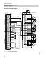
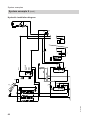
Electrical installation diagram
eZ
N,L,PE
230 V / 50 Hz
R1
R2
eI
3
3
eU
3
3
230 V / 50 Hz
M
eE
STB rR
R3
R4
R5
R6
3
M
rZ
R7
S1
S2
2
2
KOL eQ
SOL rQ
S3
S4
Low voltage
S5
S6
.
.
.
S12
CS10
Imp 1
Imp 2
V BUS
2
2
2
2
2
2
rW
rT
uQ
uW
uW
uE/uR
KM BUS
5414 620 GB
145
2
52
System examples
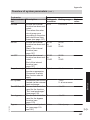
System example 7 (cont.)
Required settings on the solar control unit
Operator code
Solar options
■ System (see page 95)
Set solar values
■ Tcylset (set cylinder temperature)
■ ΔTon (start temperature differential for solar circuit
pump R1 eE)
■ ΔToff (stop temperature differential for solar circuit
pump R1 eE)
System options
■ ΔT Fct6 (ΔT function for switching the three-way
diverter valve R6 rZ, function block 2, see
page 112)
Set system values
■ ΔT6on (start temperature differential for R6)
■ ΔT6off (stop temperature differential for R6)
Delivered
Setting
condition
0000
0200
1
1
60 °C
8.0 K
4.0 K
No
Yes
5.0 K
3.0 K
For pump speed, see page 139.
In conjunction with a wall mounted oil/gas boiler
5414 620 GB
Codes required at the boiler and heating circuit control unit
Code
Function
53:3
System without DHW circulation pump:
The circulation pump for cylinder heating 4 is connected to
output sK of internal extension H1 or H2
5b:1
Internal diverter valve without function
(DHW cylinder connected downstream of the low loss
header)
53
Installation
Main menu
System examples
System example 8
Large solar thermal systems for DHW heating
■ Viessmann solar collectors
■ DHW cylinder Vitocell 100-V or
Vitocell 300-V
■ Vitocell 100-L preheating cylinder
■ Heating water buffer cylinder
Vitocell 140-E or Vitocell 160-E
■ Vitosolic 200
■ Solar-Divicon
■ Wall mounted oil/gas boiler or oil/gas
boiler
Function description
DHW heating with solar energy
Charge circuit
Solar circuit pump R1 eE starts and
heating water buffer cylinder rP is
heated up if the temperature differential
between collector temperature sensor S1 eQ and cylinder temperature sensor S2 rQ is greater than start temperature differential ΔTon.
Solar circuit pump R1 eE is stopped in
accordance with the following criteria:
■ Actual temperature dropping below
the stop temperature differential ΔToff
■ Exceeding the electronic temperature
limit of control unit eZ (max. 90 °C)
■ Reaching the temperature selected at
high limit safety cut-out rE (if installed)
Primary pump (preheating cylinder) R6
qR and discharge pump (heating water
buffer cylinder) R3 qI start in accordance with the following criteria:
54
■ The temperature differential between
buffer cylinder temperature sensor S5
rW and pre-heating cylinder temperature sensor S6 qW is greater than start
temperature differential ΔT6on
and
■ The temperature in preheating cylinder qQ is below the value set at thermostatically controlled mixing
valve qO
Discharge circuit
Preheating cylinder qQ is force-filled with
cold water. The water in preheating cylinder qQ is heated via heat
exchanger qU.
Additional function for DHW heating
The requirements for the additional function are achieved through circulation
pump R5 qT. Cylinders qP and qQ are
heated.
DHW heating without solar energy
DHW cylinder qP is heated by boiler
1. The cylinder thermostat with cylinder
temperature sensor 3 of boiler control
unit 2 regulates circulation pump for
cylinder heating 4. DHW circulation
pump qE (if installed) is controlled by
boiler control unit 2. Primary pump
(preheating cylinder) R6 qR and discharge pump (heating water buffer cylinder) R6 qI are stopped. The DHW is
routed to DHW cylinder qP via preheating cylinder qQ.
5414 620 GB
Main components
5414 620 GB
qR
qZ
qU
qI
qZ
eE
eW
eQ
qW
qO
P
qQ
eP
eZ
qT
rQ
rE
rW
qP
qE
3
rP
HR3
HR4
HV3/HR1
HR2
HV1
HV2
2
1
1
Installation
4 2
M
M
System examples
System example 8 (cont.)
Hydraulic installation diagram
55
System examples
System example 8 (cont.)
Equipment required
Pos.
1
2
3
4
qP
qE
qT
qQ
qW
qR
qZ
qU
qI
qO
eP
eQ
eW
eE
eZ
eU
eI
rP
rQ
rW
rE
5414 620 GB
uQ
uW
uE
uR
Description
Wall mounted oil/gas boiler or oil/gas boiler
with
Boiler and heating circuit control unit
Cylinder temperature sensor
Circulation pump for cylinder heating
(integrated for wall mounted oil/gas boiler)
DHW cylinder
DHW heating with solar energy
DHW circulation pump
(internal/external extension may be required for connecting a wall mounted
oil/gas boiler)
Circulation pump R5 (anti-stratification)
Preheating cylinder
Temperature sensor S6 (preheating cylinder)
Primary pump R6 (preheating cylinder)
Line regulating valve
Heat exchanger
Discharge pump R3 (heating water buffer cylinder)
Thermostatic mixing valve for hard water protection
Solar collectors
Collector temperature sensor S1 (KOL)
Solar-Divicon
Solar circuit pump R1
Vitosolic 200
Junction box
ON/OFF switch (on site)
Heating water buffer cylinder
Cylinder temperature sensor S2 (SOL)
Temperature sensor S5 (heating water buffer cylinder)
High limit safety cut-out STB
Accessories
Solar cell
Heat meter extension kit (flow meter)
Large display
Datalogger
For boiler and heating circuit accessories, see boiler scheme.
56
System examples
System example 8 (cont.)
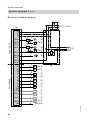
Electrical installation diagram
eZ
230 V / 50 Hz
R1
R2
R3
R4
R5
R6
3
eU
230 V / 50 Hz
3
3
3
3
3
M
eE
STB rE
M
qI
M
qT
M
qR
Installation
N,L,PE
eI
3
R7
S1
S2
2
2
KOL eQ
SOL rQ
S3
S4
Low voltage
S5
S6
.
.
.
S12
CS10
Imp 1
Imp 2
V BUS
2
2
2
2
2
2
rW
qW
uQ
uW
uW
uE/uR
KM BUS
5414 620 GB
145
2
57
System examples
System example 8 (cont.)
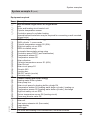
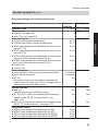
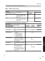
Required settings on the solar control unit
Operator code
Solar options
■ System (see page 95)
Set solar values
■ Tcylset (set cylinder temperature)
■ ΔTon (start temperature differential for solar circuit
pump R1 eE)
■ ΔToff (stop temperature differential for solar circuit
pump R1 eE)
System options
■ Add. fct.
(Additional function for DHW heating)
■ Thermost. 2, function block 1, see page 112)
■ ΔT Fct5 (ΔT function for switching discharge pump
(heating water buffer cylinder) R3 qI, function block
1, see page 112)
■ Thermost. 4, function block 2, see page 112)
■ ΔT Fct6 (ΔT function for switching the primary pump
(preheating cylinder) R6 qR, function block 2, see
page 112)
Set system values
■ Th2on (start temperature for R3)
■ Th2off (stop temperature for R3)
■ ΔT5on (start temperature differential for R3)
■ ΔT5off (stop temperature differential for R3)
■ Th4on (start temperature for R6)
■ Th4off (stop temperature for R6)
■ ΔT6on (start temperature differential for R6)
■ ΔT6off (stop temperature differential for R6)
58
Delivered
Setting
condition
0000
1
0200
1
60 °C
8.0 K
4.0 K
No
Yes
No
No
Yes
Yes
No
No
Yes
Yes
40 °C Value at the
mixing valve
qO − 10 K
45 °C Value at the
mixing valve
qO − 7K
5.0 K
10 K
3.0 K
6K
40 °C Value at the
mixing valve
qO − 10 K
45 °C Value at the
mixing valve
qO − 7 K
5.0 K
10 K
3.0 K
6K
5414 620 GB
Main menu
System examples
System example 8 (cont.)
Main menu
Sys.contractor
■ Sen.Th2
■ Sen1 ΔT5Fct
■ Sen2 ΔT5Fct
Delivered
condition
Setting
4
3
4
6
5
6
System example 9
Large solar thermal systems for DHW heating with two monomode DHW cylinders and central heating backup with heating
water buffer cylinder
Main components
■ Viessmann solar collectors
■ DHW cylinder Vitocell 100-V
■ Heating water buffer cylinder
Vitocell 140-E
■ Vitosolic 200
■ Solar-Divicon
■ Solar pump line
■ Wall mounted oil/gas boiler or oil/gas
boiler
Function description
5414 620 GB
DHW heating with solar energy
Solar circuit pump R1 eE starts and
DHW cylinder qP is heated up if the temperature differential between collector
temperature sensor S1 eQ and cylinder
temperature sensor S2 qQ exceeds the
starting temperature differential ΔT.
Solar circuit pump R1 eE is stopped in
accordance with the following criteria:
■ Actual temperature dropping below
the stop temperature differential ΔToff
■ Exceeding the electronic temperature
limit of control unit eZ (max. 90 °C)
■ Reaching the temperature selected at
high limit safety cut-out qW (if installed)
Transfer pump R5/R7 qT is started in
accordance with the following criteria:
■ The temperature differential between
sensor S7 qZ and sensor S8 qU is
greater than start temperature differential ΔT7on
■ Additional function for DHW heating is
enabled
The water heated in DHW cylinder 1 qP
is transferred to DHW cylinder 2 qI. This
way, DHW cylinder 2 qI is also heated
by solar energy.
Transfer pump R5/R7 qT stops when the
actual temperature falls below stop temperature differential ΔT7off or if the additional function ends.
DHW circulation pump qE (if installed)
for DHW cylinder 2 qI is controlled by
boiler control unit 2.
59
Installation
For pump speed, see page 139.
System examples
System example 9 (cont.)
Additional function for DHW heating
The requirements for the additional function are achieved through circulation
pump R5 qT.
Suppression of DHW cylinder reheating by the boiler
Coding address "67" in boiler control
unit 2 defaults a third set DHW temperature (setting range 10 to 95 °C). This
value must be below the first set DHW
temperature. DHW cylinder 2 qI will only
be heated by boiler 1 (solar circuit
pump R1 eE runs) if this set value cannot
be achieved by the solar thermal system.
DHW heating without solar energy
DHW cylinder 2 qI is heated by
boiler 1. The cylinder thermostat with
cylinder temperature sensor 3 of boiler
control unit 2 regulates circulation
pump for cylinder heating 4.
The temperature inside heating water
buffer cylinder rP will be limited by the
electronic temperature limiter or high
limit safety cut-out rR (if required).
Circulation pump R4 eT is stopped
roughly every 15 min for approx. 2 min,
(times adjustable), to check whether the
temperature at collector temperature
sensor S1 eQ is high enough to change
over to DHW cylinder heating qP.
Three-way diverter valve R6 rZ is
switched to position "AB-A" and the heating return water is routed to boiler 1 via
heating water buffer cylinder rP, if the
temperature differential between buffer
cylinder temperature sensor S5 rE and
heating circuit return temperature sensor S6 rT exceeds temperature differential ΔT6on. If the temperature of the
preheated return water is too low, boiler
1 reheats the water to the required flow
temperature. Three-way diverter valve
R6 rZ is switched to position "AB-B" if
the actual temperature falls below the
stop temperature differential ΔT6off.
Central heating without solar energy
Central heating with solar energy
60
Three-way diverter valve R6 rZ remains
at zero volt (position "AB-B") if the temperature differential between buffer cylinder temperature sensor S5 rE and
heating circuit return temperature sensor
S6 rT is less than temperature differential ΔT6off. There will be no flow through
heating water buffer cylinder rP.
Boiler 1 supplies the heating circuit
with heat according to the heating curve
set at boiler control unit 2.
5414 620 GB
Circulation pump R4 eT starts to heat
heating water buffer cylinder rP if DHW
cylinder 1 qP cannot be heated and the
temperature differential between collector temperature sensor S1 eQ and buffer
cylinder temperature sensor S4 rQ is
greater than start temperature differential ΔT2on. The pump will stop if the
actual temperature falls below the stop
temperature differential ΔT2off or it reaches the set buffer cylinder temperature
Tcyl2set.
System examples
System example 9 (cont.)
5414 620 GB
Installation
A low loss header 6 with flow temperature sensor 5 is required in conjunction with a wall mounted oil/gas
boiler.
61
62
5414 620 GB
eW
eE
eR
eT
eQ
qW
1
P
qP
qQ
qZ
qT
eP
qR
rQ
rR
rE
eZ
rP
2
qI
qE
HR3
HR4
3
qU
HV3/HR1
HR2
HV1
HV2
2
1
6
5
4
1
2
rZ
rT
BMA
AB
M
System examples
System example 9 (cont.)
Hydraulic installation diagram
System examples
System example 9 (cont.)
Pos.
1
2
3
4
qP
qQ
qW
qE
qR
qT
qZ
qU
eP
eQ
eW
eE
eZ
eU
eI
eO
5414 620 GB
rP
eR
eT
rQ
rE
rR
rT
rZ
uQ
uW
uE
uR
Description
Wall mounted oil/gas boiler or oil/gas boiler
with
Boiler and heating circuit control unit
Cylinder temperature sensor
Circulation pump for cylinder heating
(internal/external extension may be required for connecting a wall mounted
oil/gas boiler)
DHW heating with solar energy
DHW cylinder 1, mono-mode
Cylinder temperature sensor S2 (SOL)
High limit safety cut-out STB
DHW circulation pump
Automatic thermostatic mixing valve
Circulation pump R5/R7 (anti-stratification)
Temperature sensor S7
Temperature sensor S8
Solar collectors
Collector temperature sensor S1 (KOL)
Solar-Divicon
Solar circuit pump R1
Vitosolic 200
Junction box
ON/OFF switch (on site)
Contactor relay
Central heating with solar energy
Heating water buffer cylinder
Solar pump line
Solar circuit pump for heating buffer cylinder R4
Temperature sensor S4 (heating water buffer cylinder), heating up
Temperature sensor S5 (heating water buffer cylinder), discharge
High limit safety cut-out STB
Return temperature sensor S6 (heating circuit)
Three-way diverter valve R6
Accessories
Solar cell
Heat meter extension kit (flow meter)
Large display
Datalogger
For boiler and heating circuit accessories, see boiler scheme.
63
Installation
Equipment required
System examples
System example 9 (cont.)
Electrical installation diagram
eI
230 V / 50 Hz
eZ
L 35
N
?
eU
230 V / 50 Hz
R134
R233
R332
R431
R530
R629
R7-R
R7-M
R7-A
S1
S2
S3
S4
Low voltage
S5
S6
S7
S8
S12
CS10
Imp 1
Imp 2
3
2 eU
3
3
3
2
2
2
2
2
2
2
2
2
2
2
2
M
eE
STBqW
M
eT
M
1~ qT
STB rR
M
rZ
KOL eQ
eO
SOL qQ
rQ
rE
rT
qZ
qU
uQ
uW
uW
uE/uR
KM BUS
5414 620 GB
V BUS
145
3
64
System examples
System example 9 (cont.)
Required settings on the solar control unit
5414 620 GB
Operator code
Solar options
■ System (see page 99)
■ Hyd. Type (see page 99)
Set solar values
■ Tcylset (set cylinder temperature)
■ Tcyl2set (set buffer cylinder temperature)
■ ΔTon (start temperature differential for solar circuit
pump R1 eE)
■ ΔToff (stop temperature differential for solar circuit
pump R1 eE)
■ ΔT2on (start temperature differential for solar circuit
pump for buffer cylinder heating R4 eT)
■ ΔT2off (stop temperature differential for solar circuit
pump for buffer cylinder heating R4 eT)
■ Priority Cyl1
■ Priority Cyl2
Solar contractor
■ t-stop (duration of the pump runtime interruption)
■ t-circ. (break intervals)
■ ΔT Col
During the t-stop time the collector temperature
must rise by the value of ΔT Col to change over to
heating the consumer with priority 1.
System options
■ Add. fct.
(Additional function for DHW heating)
■ ΔT Fct6 (ΔT function for switching the three-way
diverter valve R6 rZ, function block 2, see
page 112)
■ ΔT Fct5 (ΔT function for switching the transfer pump
R5/R7 qT, function block 3, see page 112)
Set system values
■ ΔT6on (start temperature differential for R6)
■ ΔT6off (stop temperature differential for R6)
■ ΔT7on (start temperature differential for R5/R7)
■ ΔT7off (stop temperature differential for R5/R7)
Delivered
Setting
condition
0000
0200
1
1
3
2
60 °C
60 °C
8.0 K
Installation
Main menu
4.0 K
8.0 K
4.0 K
1
2
2 minutes
15 minutes
2K
No
Yes
No
Yes
No
Yes
5.0 K
3.0 K
5.0 K
3.0 K
65
System examples
System example 9 (cont.)
For pump speed, see page 139.
In conjunction with a wall mounted oil/gas boiler
5414 620 GB
Codes required at the boiler and heating circuit control unit
Code
Function
53:3
System without DHW circulation pump:
The circulation pump for cylinder heating 4 is connected to
output sK of internal extension H1 or H2
5b:1
Internal diverter valve without function
(DHW cylinder connected downstream of the low loss
header)
66
Installation sequence
Fitting the solar control unit
When selecting the installation location,
take note of the electrical connections
and cable/lead lengths.
3.
153
2x
Installation
4.
5.
6.
2.
23
3
1.
5414 620 GB
Before closing the solar control unit,
make all electrical connections and
apply a strain relief to all cables/leads.
67
Installation sequence
Overview of electrical connections
N
N
N
R2
N
N
N
N
N
R1
R3
R4
C
27 30 31 32 33 34 35
L
A
B
R5
R6
R7-R
145
9
8
7
6
PWM R1
Imp2
CS10
Imp1
S11
S10
S9
S8
S7
S6
S5
S4
S2
2
S3
S1
1
GND
S12
A Wiring chamber of the solar control
unit
B Fuse, 6.3 A (slow)
68
C Semi-conductor relay
(R1 to R4 suitable for speed control)
5414 620 GB
PWM R2
L
5
PWM R3
K
4
PWM R4
H
3
VBus
G
10 11 12 13 14 15 16 17 18 19 20
145
F
R7-A
E
R7-M
D
Installation sequence
Overview of electrical connections (cont.)
D Zero volt relay output
E KM BUS
F V BUS (e.g. connection to a large
display or to the datalogger, accessories)
G PWM signals for pumps at R1 to
R4
H Pulse counter input for connection
of flow meters
K Solar cell CS
L Sensor inputs
Installation
Sensor inputs
S1, S9
NTC sensors, 20 kΩ
(collector temperature sensor)
S2–S8
NTC sensors, 10 kΩ
(cylinder temperature sensor)
S10–S12 NTC sensors, 10 kΩ
(cylinder temperature sensor)
Pumps
Possible pumps
Standard solar circuit pumps
■ Without individual speed control (with integral
auxiliary capacitor)
■ With individual speed control
High efficiency pumps
Pumps with PWM input
Parameter "Control"
Make settings in menu "Contractor" (see page 165).
"Pulse"
"ON/OFF"
"ON/OFF"
Note
Use only solar pumps, not heating circuit
pumps.
■ WILO pump
■ GRUNDFOS pump
"PWM A"
"PWM B"
5414 620 GB
For information regarding speed control,
see page 139
69
Installation sequence
Pumps (cont.)
Installation
The circulation pump with connecting
cable is part of the Solar-Divicon pump
station.
Alternative pumps must be type-tested
and installed in accordance with the
manufacturer's details.
Separate installation and service
instructions
Connection
3-core cable with a cross-section of
0.75 mm2
Connect the neutral and earth conductors with the respective collective terminal block.
Rated current
Semi-conductor relay R1 to R6: 0.8 A
Notes
■ Connect pumps that draw more than
190 W via an additional relay. Parameter "Control" must not be set to
"Pulse" (see page 140).
■ Connect only one pump each to outputs R1 to R6.
Example: Connection of one pump without PWM input to R1
A
27 30 31 32 33 34 35
M
1~
A Wiring chamber of the solar control
unit
70
B Pump
5414 620 GB
B
Installation sequence
Pumps (cont.)
Example: Connection of one pump with PWM input to R1
145
145
VBus
PWM R4
PWM R3
PWM R2
PWM R1
A
27 30 31 32 33 34 35
Installation
16 17 18 19 20
M
1~
B
A Wiring chamber of the solar control
unit
B Pump
High limit safety cut-out
A high limit safety cut-out in the consumer, e.g. the DHW cylinder, is
required when less than 40 litres cylinder
volume is available per m2 absorber
area. This installation safely prevents
temperatures in excess of 95 °C in the
consumer.
Note
For the Vitocell 100, observe the max.
collector area that can be connected.
5414 620 GB
Installation
Install the sensor of the high limit safety
cut-out inside the cylinder cap (Vitocell
300 accessory).
Cylinder cap installation instructions
71
Installation sequence
High limit safety cut-out (cont.)
Connection
■ 3-core cable with a cross-section of
1.5 mm2.
■ Systems with two collector arrays with
one solar circuit pump require 2 high
limit safety cut-outs.
■ The changeover contact of the high
limit safety cut-out allows a fault message to be issued. For this, observe
the influence of the speed control on
the message signal. If necessary, set
parameter "Control" to "On/Off" (see
page 140).
A
27 30 31 32 33 34 35
E
B
?
M
1~
D
A Wiring chamber of the solar control
unit
B Junction box (on site)
C Solar circuit pump or primary pump
for additional consumers with high
limit safety cut-out
72
D High limit safety cut-out
E Fault message facility
5414 620 GB
C
Installation sequence
High limit safety cut-out (cont.)
Temperature setting
Delivered condition: 120 °C
Requires adjustment to 95 °C
High limit safety cut-out installation instructions
Central fault message facility
R1
R2
R3
R5
R6
R7-R
R7-M
R7-A
A
Netz
Réseau électrique T6,3A
Red eléctrica
230V
AC 250V 0,8 A
AC 250V 4(2) A
T40
IP20
230V ~ 50-60 Hz
P = 3VA
R4
R1-R6
R7
Installation
■ In accordance with the diagram, a central fault message facility can be connected to the zero volt output R7. This
relay is then unavailable for any other
function.
■ For settings, see page 141.
L
N
27 30 31 32 33 34 35
N
N
D
N
N
N
B
?N L
5414 620 GB
C
A Wiring chamber of the solar control
unit
B ON/OFF switch (on site)
C Power supply
D Central fault message facility
73
Installation sequence
Sensors
Collector temperature sensor
Installation
Collector installation instructions
Connect sensor to S1 or, in conjunction
with 2 collector arrays to S9.
Extension of the connecting lead:
2-core cable with a cross-section of
1.5 mm2.
Connection
In accordance with system example and
page 68.
Note
Never route this lead together with
230/400 V cables.
Cylinder temperature sensor
Installation
Vitocell 100-B and Vitocell 300-B
With the threaded elbow.
Installation instructions for the
DHW cylinder
Vitocell 100-V and Vitocell 300-V
3.
1.
2.
5414 620 GB
A Heating water return connection
74
Installation sequence
Sensors (cont.)
Connection
2-core cable with a cross-section of
1.5 mm2.
In accordance with system example and
page 68.
Extension of the connecting lead:
Connect sensor to S2.
Note
Never route this lead together with
230/400 V cables.
Temperature sensors
Installation
Installation
1.
2.
4.
3.
5414 620 GB
Note
Never wrap insulating tape around the
sensor.
Seal in the sensor well.
Temperature sensor (swimming pool):
■ Install sensor into the swimming pool
return, upstream of the heat
exchanger.
■ Installation in accordance with the
details provided by the swimming pool
manufacturer or the installation
instructions of any installed heat
exchanger
75
Installation sequence
Sensors (cont.)
Connection
In accordance with system example and
page 68.
Extension of the connecting lead:
2-core cable with a cross-section of
1.5 mm2.
Note
Never route this lead together with
230/400 V cables.
Solar cell
Installation
Separate installation instructions
An identifying letter (type of solar cell) is
visible on the solar cell. For commissioning, enter this in the table on page 164
under "Solarcell type".
Connection
Note
Observe polarity.
Never route this lead together with
230/400 V cables.
VBus
PWM R4
PWM R3
PWM R2
PWM R1
Imp2
Imp1
CS10
S12
S11
S10
S9
A
S8
2-core cable with a cross-section of
0.75 mm2.
Extension of the connecting lead:
2-core cable with a cross-section of
1.5 mm2.
GND
8
9
10 11 12 13 14 15 16 17 18 19 20
BU
BN
A Wiring chamber of the solar control
unit
B Solar cell CS10
76
5414 620 GB
B
Installation sequence
Solar cell (cont.)
Settings
See page 164.
Power supply
Regulations
R1
R2
R3
R5
R6
R7-R
R7-M
R7-A
A
Netz
Réseau électrique T6,3A
Red eléctrica
230V
AC 250V 0,8 A
AC 250V 4(2) A
T40
IP20
230V ~ 50-60 Hz
P = 3VA
R4
R1-R6
R7
Installation
Make the power supply connection and
implement all earthing measures (i.e.
RCD circuit) in accordance with
IEC 60364-4-41, the requirements of
your local power supply utility, VDE or
national regulations.
L
N
27 30 31 32 33 34 35
N
N
N
N
N
B
L
N
C
?
5414 620 GB
A Wiring chamber of the solar control
unit
B Mains isolator, two-pole (on site)
C Mains voltage 230 V/50 Hz
77
Installation sequence
Power supply (cont.)
■ Protect the cable to the control unit
with an appropriate fuse/MCB.
■ Disconnect the system by means of a
device that simultaneously separates
all non-earthed conductors with
at least 3mm contact separation.
■ Connect the power supply in accordance with the diagram.
5414 620 GB
Danger
Incorrect core termination can
cause severe injuries and damage to the equipment.
Never interchange cores "L" and
"N".
L brown
N blue
PE green/yellow
78
Commissioning
Switching the power ON
1. Check whether all electrical connections have been correctly made.
2. Check that the high limit safety cutout and temperature limiter (if
required) are connected.
3. Switch ON the power; the solar control unit then begins an initialising
phase.
The standard display then appears
(see following diagram).
The solar control unit is now in automatic mode.
Navigation through the menu
Controls
10:59
Tcol
47.7 °C
Tcylb
35.4 °C
A
A
/
■ Back to the previous menu point
■ Terminating an adjustment
already begun (the value
reverts to its previous setting)
Cursor keys
Navigation through the menu
The display can only show four
lines of the menu at a time. The
arrow on the l.h. side of the display
highlights the available menu
item.
5414 620 GB
B
Standard display
The standard display will automatically show after approx. 4 min, if
no adjustments are made.
OK key
■ Pressed once: Confirmation of
the menu selection
■ Pressed twice: Confirmation of
a value change
■ Calling up the main menu
■ Back to the standard display
from any menu
B
79
Service
30.04.2009
Commissioning
Navigation through the menu (cont.)
/
Cursor keys
To display values (with graphic
support; see the following diagram)
A
ΔT1on
8.0K
1.5
=8.0
20.0
B
C
A Parameters
B Minimum value
C Maximum value
Entering the operator code
Press the following keys:
1.
2.
"Hauptmenü" will be displayed.
Hauptmenü:
Messwerte
Meldungen
Solar
for "Bedienercode" (lowest
menu point).
Hauptmenü:
SD-Karte
Manuellbetrieb
Bedienercode
3. OK
to confirm.
Bedienercode:
5414 620 GB
0000
80
Commissioning
Entering the operator code (cont.)
4.
/
for "0200".
Confirm every figure with OK.
Key sequence: OK/ / / OK/
OK/ OK
Note
After commissioning set the operator
code to "0000".
Language selection
Press the following keys:
3. OK
to confirm.
1.
4.
for "Sprache" (lowest menu
point).
"Hauptmenü" will be displayed.
Hauptmenü:
Messwerte
Meldungen
Solar
2.
for "Experte" (lowest menu
point).
5. OK
to confirm.
6.
for the required language.
/
7. OK
to confirm.
5414 620 GB
Service
Hauptmenü:
Manuellbetrieb
Bedienercode
Experte
Experte:
Uhr
Display
Sprache
81
Commissioning
Setting the time and date
Make the following settings at the
solar control unit:
For further time adjustments, see
page 166.
Main menu
■ "System"
■ "Setting values"
– "Time"
First set the hour, then the minutes.
– "Date"
Set the year, month and day in that
order.
Adjusting the display
The level of backlighting and font colour
can be selected (black on a white background or vice-versa) (see page 166).
Setting parameters
Selecting the system and hydraulic type
System:
■ How many collector arrays have been
installed?
■ How many consumers have been
installed?
Hydraulic type:
■ Which hydraulic version (pump or
valve control)?
82
Note
By selecting the "System" and "Hyd.
Type" relays and sensors are automatically assigned.
Make the following settings at the
solar control unit:
Main menu
■ "Solar"
■ "Options"
– "System"
Delivered condition: 1
Set a value.
– "Hyd. Type"
Delivered condition: 1
Set a value.
5414 620 GB
Prior to setting the system parameters,
the "System" and "Hyd. Type" (see
chapter "Systems" from page 94) must
be selected in accordance with the following criteria:
Commissioning
Setting parameters (cont.)
Note
All parameters are reset into their delivered condition when the setting for "System" is changed.
Setting pump parameters
Check which type of pumps are connected and set parameter "Control"
accordingly (see page 69).
Activating additional functions
5414 620 GB
■ For each system, additional functions
can be activated (see the table for the
respective system from page 95).
Functions for which the same relay
output is used can only be used alternately.
Example system 1 (see page 95):
The "Parallel relay" function can only
be activated if no additional function
for DHW heating was activated.
■ For functions that can be selected
independently of the relay assignment, see the following table.
Page
117
118
127
128
129
129
130
134
134
135
135
83
Service
Function
Cylinder priority control
(only in conjunction with several consumers, systems 3 to 5)
Collector emergency stop
Interval function
Collector cooling function
Return cooling function
Frost protection
Target temperature
Cylinder (2 to 4)
Overheat
Collector minimum limit
Cyclical heating
Commissioning
Setting parameters (cont.)
Resetting parameters into their delivered state
Make the following settings at the
solar control unit:
Main menu
■ "Solar"
■ "Options"
– "System"
Set value "1".
Carrying out a relay test (testing actuators)
The relays can be switched individually
or together.
Make the following settings at the
solar control unit:
Main menu
■ "Manual mode"
– "All relays"
or
– "Relay 1"
to
"Relay 7"
Note
If a relay is in manual mode, the standard
display will indicate accordingly:
30.04,2009
10:59
Tcol
47.7 °C
Tcylb
35.4 °C
Manual mode
Switching states:
■ "ON"
■ "Auto" ≙ Controlled operation
■ "OFF"
5414 620 GB
After the relay test has been completed,
select "Auto" for all relays.
84
Service scans
Scanning temperatures and operating conditions
Subject to system configuration, the following values can be scanned with keys
/ :
°C
°C
°C
°C
°C
°C
°C
°C
–
–
–
Explanation
Collector temperature
Collector temperature, collector array 2
Cylinder temperature, bottom
Cylinder temperature, consumer 2, bottom
Cylinder temperature, consumer 3, bottom
Cylinder temperature, consumer 4, bottom
Bypass temperature
Temperature external heat exchanger
Additional function for DHW heating is active
% Speed, relay 1 to 4
– Switching state, relays 5 to 7
°C Temperature sensors 1 to 12
Display when there is a sensor break: 888.8
Display when there is a sensor short circuit: −888.8
Note
The temperature can also be displayed in °F (degree
Fahrenheit) (selection, see 165)
Intens.
W/qm Insolation intensity (actual insolation) in conjunction
with the solar cell
5414 620 GB
Scanning the statement
Subject to system configuration, the following values can be scanned with keys
/ :
Main menu
■ "Solar"
■ "Statement"
85
Service
"Actual values:"
Tcol
Tcol2
Tcylb
Tcyl2b
Tcyl3b
Tcyl4b
Tby
T-HE
Cyl. add.
Time
Date
Relay
Relay 1
to
Relay 4
Relay 5
to
Relay 7
Sensors
Sen.1
to
Sen.12
Main menu
■ "Actual values"
Service scans
Scanning the statement (cont.)
"Solar statement:"
Colmax
Col2max
Cylmax
Cyl2max
Cyl3max
Cyl4max
Relay 1
to
Relay 7
Days
°C
°C
°C
°C
°C
°C
h
Explanation
Maximum collector temperature, collector array 1
Maximum collector temperature, collector array 2
Maximum DHW cylinder temperature
Maximum cylinder temperature, consumer 2
Maximum cylinder temperature, consumer 3
Maximum cylinder temperature, consumer 4
Hours run for relays R1 to R7
– Days run, solar control unit
To reset the values, except for days
run:
2. OK to confirm.
Whilst this value is displayed, press the
following keys:
1. OK "Delete?""Yes" is displayed.
Scanning the heat yield and temperatures
Main menu
■ "HM"
■ "HM 1"
or
"HM 2"
■ "Tflow" (heat meter flow temperature)
■ "Tretn" (heat meter return temperature)
■ "Heat"
Note
Add the values for Wh, kWh and MWh
together.
86
Resetting the amount of heat
Whilst this value is displayed, press the
following keys:
1. OK "Delete?""Yes" is displayed.
2. OK to confirm.
5414 620 GB
For a description of the heat statement,
see from page 141.
Service scans
Scanning messages
Main menu
■ "Messages"
"Messages:"
Loading cyl...
(only with several consumers)
Pause cyl...
(only with several consumers)
Cyl set...
Fault
SW version
HW version
Explanation
Consumer displayed is being heated.
Only in conjunction with cyclical heating (see
page 135):
Pause in the heating of the displayed consumer.
Consumer displayed has reached its set
value.
A fault has occurred at the solar control unit (for
"Scanning the fault display", see page 88).
Software version
Hardware version
Priority of the displayed messages in the standard display
Manual mode
Fault
Loading cyl...
Pause cyl...
5414 620 GB
Service
■
■
■
■
87
Troubleshooting
Fault messages
If the system develops faults, the display
backlighting flashes and "Fault" will be
displayed.
30.04.2009
Tcol
Tcylb
Fault
10:59
47.7 °C
35.4 °C
2.
for "Messages".
3. OK to confirm.
4.
for scanning the fault.
5. OK to acknowledge.
6.
for scanning further faults (see
the following table).
Checking and acknowledging faults
Press the following keys:
"Main menu" will be displayed.
5414 620 GB
1.
Note
If an acknowledged fault is not removed,
the fault message will be re-displayed.
88
Troubleshooting
Fault messages (cont.)
"Messages:"
"Fault"
!Interruption
>Sensor <
!Sensor circuit
>Sensor <
?Night circ.
Cause
The sensor has suffered a
break
The sensor has suffered a
short circuit
Recirculation via gravity
Remedy
Check the sensor concerned (see page 92).
Check the sensor concerned (see page 92).
Check any installed nonreturn damper (Solar-Divicon) or install one.
Circulation pump faulty.
Message only if solar
heating takes place for
longer than 20 min at a
temperature differential
between collector and
consumer greater than
50 K.
Internal fault.
Check pump connection
and pump.
Note
A central fault message
facility that may be connected to relay R7 will not be
switched ON.
?ΔT too high
See information above.
!EEPROM
!Processors
5414 620 GB
!SD module fault
SD fault
Switch solar control unit
OFF and ON again after a
brief interval. Check all settings. If the fault recurs,
replace the solar control
unit.
Display cause of the fault: See page 147.
Press OK (see
page 147).
89
Service
Displayed faults
Troubleshooting
Fault messages (cont.)
Faults without display
■ Solar circuit pump runs hot, but no heat transport from the collector array
to the consumer
■ Flow and return lines are equally hot
■ Noisy pipework
Air in the system? ⇒
No
Yes
A dirt trap may be
Vent the system (see collector service instructions).
blocked.
Clean dirt trap.
The solar circuit pump starts briefly, then stops and starts again, etc:
Temperature differential ΔT too small? ⇒
No
Yes
Collector temperature sensor located
Change "ΔTon" and "ΔToff"
incorrectly?
(see page 151).
No
Yes
Check interval func- Locate the collection (see
tor temperature
page 127).
sensor at the hottest place on the
solar flow.
5414 620 GB
The solar circuit pump starts too late:
Start temperature differential "ΔTon" too great? ⇒
No
Yes
Collector temperature sen- Change "ΔTon" and "ΔToff" (see page 151).
sor located incorrectly?
If yes, poss. activate interval function (see
page 127).
90
Troubleshooting
Fault messages (cont.)
Very large temperature differential between the collector array and consumers
during operation (heat cannot be dissipated):
Solar circuit pump faulty? ⇒
No
Yes
Check the solar circuit pump:
Solar heat exchanger scaled up? ⇒
■ Check the operating voltage
No
Yes
(ON/OFF switch, power
Solar heat exchanger blocked? Descale solar
cable).
heat
⇒
■ Check fuse F1, 6.3 A (slow).
exchanger.
No
Yes
If fuse F1 is faulty; replace it
Solar heat
Flush the solar
(see page 93).
exchanger
thermal sys-
5414 620 GB
The solar circuit pump does not run, although the temperature in the collector
array is higher than that in the consumer.
Display dark?⇒
Yes
No
■ Check the operating voltage (ON/OFF Check whether the solar circuit pump
switch, power cable).
runs in manual mode (see page 84).
■ Check fuse F1, 6.3 A (slow).
No
Yes
If fuse F1 is faulty; replace it (see
Is pump current enabled
Start tempage 93).
by the solar control unit? perature differential
⇒
"ΔTon" too
No
Yes
Check fuse Solar circuit great?
If yes,
F1, 6.3 A
pump
change
(slow).
seized.
value (see
If fuse F1 is Free the
faulty;
pump shaft. page 151).
replace it
Replace the
(see
pump if it
page 93).
refuses to
Otherwise
run.
replace
solar control unit.
91
Service
sized too small. tem (see collector service
instructions).
Troubleshooting
Checking sensors
1000
100
Resistance in kΩ
10
1
B
0.1
-20
0
20 25
Temperature in °C
40
60
80
100
A
120
140
A Resistance 20 kΩ
(sensor S1, S9, collector temperature sensor)
B Resistance 10 kΩ
(sensors S2 to S8, S10 to S12)
1. Disconnect the respective sensor
and measure its resistance.
2. Compare the measurement with the
actual temperature (for scanning see
page 85). Check the installation and,
in case of severe deviation, replace
the sensor.
Sensor NTC
Protection
Permissible ambient
temperature
■ during operation
■ during storage and
transport
10 kΩ at 25 °C
IP 53
20 kΩ at 25 °C
IP 53
−20 to + 90 °C
−20 to + 70 °C
−20 to + 200 °C
−20 to + 70 °C
Checking relays (actuators)
See chapter "Relay test" on page 84.
92
5414 620 GB
Specification
Troubleshooting
Changing the fuse
R1
R2
R3
R5
R6
R7-R
T40
IP20
230V ~ 50-60 Hz
P = 3VA
R7-M
R7-A
A
Netz
Réseau électrique T6,3A
Red eléctrica
230V
AC 250V 0,8 A
AC 250V 4(2) A
R4
R1-R6
R7
L
N
B
27 30 31 32 33 34 35
N
N
N
N
N
N
N
A Solar control unit wiring chamber
B Fuse, 6.3 A (slow)
5414 620 GB
Service
Open the solar control unit wiring chamber.
A spare fuse is included in the fuse
holder.
93
Function description
Systems
■ With the Vitosolic 200 solar control unit
7 systems with different hydraulic
types can be implemented.
■ System selection in accordance with
the number of collector arrays and
consumers.
■ Selection of the hydraulic type in
accordance with the hydraulic connection (e.g. via pumps or valves).
■ For each system, additional functions
can be activated (see the table for the
respective system from page 95).
Functions for which the same relay
output is used can only be used alternately.
For explanations and settings see
from page 112.
Overview
System
Number of collector
arrays
Number of consumers
Delivered condition:
1 (see page 95)
2 (see page 96)
3 (see page 98)
4 (see page 101)
5 (see page 105)
6 (see page 107)
5414 620 GB
7 (see page 110)
94
Function description
Systems (cont.)
System 1
S1
R1
S2
Relay and sensor assignment
5414 620 GB
Assignment by
scheme
Function block 1
Cooling function
Ext. Heat exchanger
Additional function
Parallel relay
Function block 2
DHW heating
Bypass
Function block 3
Central fault message
Booster suppression*3
*3
Relay R...
1 2 3 4
x
5
6
7
x
x
Sensor S...
1 2 3 4
x x
x
x
5
6
x
x
x
x
7
8
x
x
9
x
x
x
x
x
x
x
x
x
x
x
Service
Functions
Only if this function is achieved via contact control (see page 132).
95
Function description
Systems (cont.)
System 2
Hydraulic type 1
S1
R1
S9
R2
S2
*3
Only if this function is achieved via contact control (see page 132).
96
5414 620 GB
Relay and sensor assignment
Functions
Relay R...
Sensor S...
1 2 3 4 5 6 7 1 2 3 4 5 6 7 8 9
Assignment by
x x
x x
x
scheme
Function block 1
x
x x
Cooling function
x
Ext. Heat exchanger
x
x
Additional function
x
Parallel relay
x
Function block 2
x
x x
DHW heating
x
x x
Bypass
x
x
Function block 3
x
x x
Central fault message
x
x
Booster suppression*3
Function description
Systems (cont.)
Hydraulic type 2
S1
R1
S9
R2
R4
S2
5414 620 GB
*3
5
6
7
Sensor S...
1 2 3 4
x x
x
x
5
6
x
x
x
x
7
8
x
x
9
x
x
x
x
x
x
x
x
x
x
x
Service
Relay and sensor assignment
Functions
Relay R...
1 2 3 4
Assignment by
x x
x
scheme
Function block 1
x
Ext. Heat exchanger
x
Cooling function
x
Additional function
Parallel relay
Function block 2
DHW heating
Bypass
Function block 3
Central fault message
Booster suppression*3
Only if this function is achieved via contact control (see page 132).
97
Function description
Systems (cont.)
System 3
Hydraulic type 1
S1
R4
R1
S4
Relay and sensor assignment
Functions
Relay R...
1 2 3 4
Assignment by
x
x
scheme
Function block 1
x
Ext. Heat exchanger
x
Additional function
Parallel relay
Function block 2
DHW heating
Bypass
x
Function block 3
Central fault message
Booster suppression*3
*3
5
6
7
Sensor S...
1 2 3 4
x x
x
x
x
5
6
x
x
x
x
8
x
x
9
x
x
x
x
x
x
x
x
x
Only if this function is achieved via contact control (see page 132).
98
7
5414 620 GB
S2
Function description
Systems (cont.)
Hydraulic type 2
S1
S2
R4
5414 620 GB
Relay and sensor assignment
Functions
Relay R...
1 2 3 4
Assignment by
x
x
scheme
Function block 1
x
Ext. Heat exchanger
x
Additional function
Parallel relay
Function block 2
DHW heating
Bypass
x
Function block 3
Central fault message
Booster suppression*3
*3
5
6
7
Sensor S...
1 2 3 4
x x
x
x
x
5
6
x
x
x
x
7
8
x
x
9
x
x
x
x
x
x
x
x
x
Service
R1
S4
Only if this function is achieved via contact control (see page 132).
99
Function description
Systems (cont.)
Hydraulic type 3
S1
R1
S2
R4
Relay and sensor assignment
Functions
Relay R...
1 2 3 4
Assignment by
x x
x
scheme
Function block 1
x
Ext. Heat exchanger
x
Additional function
Parallel relay
Function block 2
DHW heating
Bypass
Function block 3
Central fault message
Booster suppression*3
*3
5
6
7
Sensor S...
1 2 3 4
x x
x
x
x
5
6
x
x
x
x
8
x
x
9
x
x
x
x
x
x
x
x
x
x
Only if this function is achieved via contact control (see page 132).
100
7
5414 620 GB
R2
S4
Function description
Systems (cont.)
System 4
Hydraulic type 1
S1
R1
S9
R2
S2
S4
R4
5414 620 GB
*3
5
6
7
Sensor S...
1 2 3 4
x x
x
x
x
5
6
x
x
x
x
7
8
x
x
9
x
x
x
x
x
x
x
x
x
x
x
Service
Relay and sensor assignment
Functions
Relay R...
1 2 3 4
Assignment by
x x
x
scheme
Function block 1
x
Ext. Heat exchanger
x
Additional function
Parallel relay
Function block 2
DHW heating
Bypass
Function block 3
Central fault message
Booster suppression*3
Only if this function is achieved via contact control (see page 132).
101
Function description
Systems (cont.)
Hydraulic type 2
S1
R2
S2
R3
S4
R4
Relay and sensor assignment
Functions
Relay R...
1 2 3 4
Assignment by
x x x x
scheme
Ext. Heat exchanger
Additional function
Parallel relay
Function block 2
DHW heating
Bypass
Function block 3
Central fault message
Booster suppression*3
*3
5
6
7
x
x
x
Sensor S...
1 2 3 4
x x
x
5
6
x
x
x
x
8
x
x
9
x
x
x
x
x
x
x
x
x
Only if this function is achieved via contact control (see page 132).
102
7
5414 620 GB
R1
S9
Function description
Systems (cont.)
Hydraulic type 3
S1
R1
S9
R2
S2
R3
S4
R4
5
6
7
x
x
x
Sensor S...
1 2 3 4
x x
x
5
6
x
x
x
x
7
8
x
x
9
x
x
x
x
x
x
x
x
x
5414 620 GB
Service
Relay and sensor assignment
Functions
Relay R...
1 2 3 4
Assignment by
x x x x
scheme
Ext. Heat exchanger
Additional function
Parallel relay
Function block 2
DHW heating
Bypass
Function block 3
Central fault message
Booster suppression*3
*3
Only if this function is achieved via contact control (see page 132).
103
Function description
Systems (cont.)
Hydraulic type 4
S1
R1
S9
R2
R3
S2
S4
R4
*3
5
6
7
x
x
x
Sensor S...
1 2 3 4
x x
x
5
6
x
x
x
x
8
x
x
9
x
x
x
x
x
x
x
x
x
Only if this function is achieved via contact control (see page 132).
104
7
5414 620 GB
Relay and sensor assignment
Functions
Relay R...
1 2 3 4
Assignment by
x x x x
scheme
Ext. Heat exchanger
Additional function
Parallel relay
Function block 2
DHW heating
Bypass
Function block 3
Central fault message
Booster suppression*3
Function description
Systems (cont.)
System 5
Hydraulic type 1
S1
R1
R2
S4
R4
S5
R5
5414 620 GB
Relay and sensor assignment
Functions
Relay R...
1 2 3 4
Assignment by
x x
x
scheme
Function block 1
x
Ext. Heat exchanger
x
Additional function
x
Function block 2
DHW heating
Bypass
Function block 3
Central fault message
Booster suppression*3
*3
5
x
6
7
Sensor S...
1 2 3 4
x x
x
x
x
x
x
x
5
x
6
x
x
x
x
7
8
x
x
9
x
x
x
x
x
Service
S2
Only if this function is achieved via contact control (see page 132).
105
Function description
Systems (cont.)
Hydraulic type 2
S1
R1
S4
R2
S5
R4
Relay and sensor assignment
Functions
Relay R...
1 2 3 4
Assignment by
x x
x
scheme
Function block 1
x
Ext. Heat exchanger
x
Additional function
Parallel relay
Function block 2
DHW heating
Bypass
Function block 3
Central fault message
Booster suppression*3
*3
5
6
7
Sensor S...
1 2 3 4
x x
x
x
x
5
x
6
x
x
x
x
8
x
x
9
x
x
x
x
x
x
x
x
x
x
Only if this function is achieved via contact control (see page 132).
106
7
5414 620 GB
S2
Function description
Systems (cont.)
System 6
Hydraulic type 1
S1
S9
R1
R2
S2
R4
S4
R5
S5
R6
5
x
6
x
7
Sensor S...
1 2 3 4
x x
x
x
x
5
x
6
7
8
x
x
9
x
x
x
x
x
5414 620 GB
Service
Relay and sensor assignment
Functions
Relay R...
1 2 3 4
Assignment by
x x
x
scheme
Function block 1
x
Ext. Heat exchanger
x
Additional function
x
Function block 3
Central fault message
Booster suppression*3
*3
Only if this function is achieved via contact control (see page 132).
107
Function description
Systems (cont.)
Hydraulic type 2
S1
S9
R6
S2
R1
S4
R2
S5
R4
Relay and sensor assignment
Functions
Relay R...
1 2 3 4
Assignment by
x x
x
scheme
Function block 1
x
Ext. Heat exchanger
x
Additional function
x
Bypass
Function block 3
Central fault message
Booster suppression*3
*3
5
x
6
x
7
Sensor S...
1 2 3 4
x x
x
x
x
x
x
x
x
5
x
7
8
x
x
9
x
x
x
Only if this function is achieved via contact control (see page 132).
108
6
5414 620 GB
R5
Function description
Systems (cont.)
Hydraulic type 3
S1
S9
R1
R2
R3
S2
R4
S4
R5
S5
R6
5
x
6
x
7
x
x
x
x
x
Sensor S...
1 2 3 4
x x
x
5
x
6
7
8
x
x
9
x
x
x
5414 620 GB
Service
Relay and sensor assignment
Functions
Relay R...
1 2 3 4
Assignment by
x x x x
scheme
Ext. Heat exchanger
Bypass
Function block 3
Central fault message
Booster suppression*3
*3
Only if this function is achieved via contact control (see page 132).
109
Function description
Systems (cont.)
System 7
Hydraulic type 1
S1
R1
R2
S4
R4
S5
R5
S6
R6
Relay and sensor assignment
Functions
Relay R...
1 2 3 4
Assignment by
x x
x
scheme
Function block 1
x
Ext. Heat exchanger
x
Additional function
x
Bypass
Function block 3
Central fault message
Booster suppression*3
*3
5
x
6
x
7
Sensor S...
1 2 3 4
x x
x
x
x
x
x
x
x
5
x
7
8
x
x
9
x
x
Only if this function is achieved via contact control (see page 132).
110
6
x
5414 620 GB
S2
Function description
Systems (cont.)
Hydraulic type 2
S1
R1
S4
R2
S5
R4
S6
R5
5414 620 GB
Relay and sensor assignment
Functions
Relay R...
1 2 3 4
Assignment by
x x
x
scheme
Function block 1
x
Ext. Heat exchanger
x
Additional function
x
Function block 2
Parallel relay
Bypass
Function block 3
Central fault message
Booster suppression*3
*3
5
x
6
7
Sensor S...
1 2 3 4
x x
x
x
x
x
x
x
5
x
6
x
7
8
x
x
9
x
x
x
x
x
Service
S2
Only if this function is achieved via contact control (see page 132).
111
Function description
Function blocks
■ In the delivered condition, certain sensors are assigned to these functions
(Reference sensors). These sensors
can be switched, i.e. sensors already
used can be used for additional functions (see page 161).
■ Make all settings in menu "System"
(see from page 158).
A relay assigned to a function block will
only switch if the conditions of all activated functions are met. These functions act like individual switches in a
serial circuit (see the following diagram).
5414 620 GB
■ If the relays 3, 6 and 7 have not been
assigned by the scheme ("System"),
they could, for example, be used for
the Function blocks 1 to 3 (see the
table for the respective system from
page 95).
■ Within a function block, there are 4
functions that can be combined as
required:
– 2 thermostat functions
– 1 temperature differential control
– 1 time switch with three periods that
can be activated
112
Function description
Function blocks (cont.)
Function block 1
Function block 2
Function block 3
Thermost.1
(Sensor S3)
Th1on
Th1off
Thermost.3
(Sensor S5)
Th3on
Th3off
Thermost.5
(Sensor S7)
Th5on
Th5off
Thermost.2
(Sensor S4)
Th2on
Th2off
Thermost.4
(Sensor S6)
Th4on
Th4off
Thermost.6
(Sensor S8)
Th6on
Th6off
∆T-Fct5
(S3-S4)
∆T5on
∆T5off
∆T-Fct6
(S5-S6)
∆T6on
∆T6off
∆T-Fct7
(S7-S8)
∆T7on
∆T7off
Time switch 1
t-on
t-off
Time switch 2
t-on
t-off
Time switch 3
t-on
t-off
R3
R6
R7
Service
Thermostat function
5414 620 GB
The respective relay switches subject to
the temperature at the reference sensor
(see the following table).
113
Function description
Function blocks (cont.)
Different effects can be achieved by determining the start and stop temperatures:
"Thon" < "Thoff"
"Thon" > "Thoff"
Adjusting the values see from
Adjusting the values, see from
page 158.
page 158.
e.g. for reheating
e.g. for utilising excess heat
Thoff
Thon
Thon
Thoff
R on
R off
R on
R off
See also example 1 on page 114 and
example 2 on page 115.
Differential temperature control (ΔT control)
The corresponding relay switches ON if
the start temperature differential is
exceeded and OFF if the stop temperature is not achieved.
Adjusting the values, see from
page 158.
Also see example 2 on page 115.
Time switch
The corresponding relay switches ON at
the start time "t on" and OFF at the stop
time "t off" (3 periods can be activated).
Adjusting the values, see from
page 159.
See also the following example.
Example 1 — Switching a DHW circulation pump
5414 620 GB
Used functions:
■ Thermostat function 1
■ Time switch 1
114
Function description
Function blocks (cont.)
S3
R3
Thermost.1
Time switch 1
R3
Th1on < 50 °C
Th1off > 55 °C
To switch a DHW circulation pump, activating the time switch is sufficient. The
DHW circulation pump can also be started subject to temperature with the sensor S3 in the DHW circulation line.
For parameters in the delivered condition, see from page 158.
Make the following settings at the
solar control unit:
2. Main menu
■ "System"
■ "Setting values"
– "Th1on"
Set "50".
– "Th1off"
Set "55".
– "Time switch 1"
Select period "t on" and "t off".
Service
1. Main menu
■ "System"
■ "Options"
– "Thermost. 1"
Set "Yes".
– "Time switch 1"
Set "Yes".
5414 620 GB
Example 2— Switching the boiler circuit pump of a solid fuel
boiler
Used functions:
■ Thermostat function 1
■ "ΔT-Fct5"
115
Function description
Function blocks (cont.)
S3
S5
R3
Thermost. 1
ΔT-Fct5
Th1on > 65 °C
Th1off < 60 °C
S3-S5 > ΔT5on
■ Boiler circuit pump R3 on:
Temperature differential "ΔT5on" is
exceeded and "Th1on" is reached
■ Boiler circuit pump R3 off:
Temperature differential "ΔT5off" or
"Th1off" is not reached
For parameters in the delivered condition, see from page 158.
Make the following settings at the
solar control unit:
1. Main menu
■ "System"
■ "Options"
– "Thermost.1"
Set "Yes".
– "ΔT-Fct5"
Set "Yes".
R3
2. Main menu
■ "System"
■ "Setting values"
– "Th1on"
Set "65".
– "Th1off"
Set "60".
– "ΔT5on"
Set a value.
– "ΔT5off"
Set a value.
3. Switch sensor S4:
Main menu
■ "System"
■ "Contractor"
– "Sen2 ΔT5Fct"
Set "5".
The solar circuit pump starts; the cylinder
is heated:
■ When the selected start temperature
differential "ΔTon" is exceeded.
116
5414 620 GB
Cylinder temperature control
Function description
Cylinder temperature control (cont.)
The solar circuit pump stops; cylinder
heating terminates in accordance with
the following criteria:
■ When the selected stop temperature
differential "ΔToff" is not reached.
■ The corresponding consumer is
blocked (sensor faulty or high limit
temperature of 90 °C is reached).
■ The collector array concerned is
blocked (collector temperature sensor
faulty or the temperature for an emergency shutdown of the collector "Tcolemoff" (see page 154) has been
reached.
■ Set cylinder temperature "Tcyl set"
(see page 151) has been reached.
Make the following settings at the
solar control unit:
Main menu
■ "Solar"
■ "Setting values"
– "ΔTon"/"ΔToff"
Set a value.
Cylinder temperature limit
Make the following settings at the
solar control unit:
Main menu
■ "Solar"
■ "Contractor"
– "ΔT-Cylset"
Set a value.
Service
When the set temperature "Tcyl set"
has been exceeded (see page 151) the
corresponding circulation pump stops to
prevent the consumer overheating. If the
consumer cools down by more than "ΔTCylset", it will be heated again by the
solar thermal system.
A safety shutdown occurs when the
safety temperature of 90 °C has been
reached.
Cylinder priority control
Note
Consumers with the same priority value
are heated up simultaneously. We cannot recommend this setting.
5414 620 GB
The consumers are heated up in numerical sequence, until the respective set
temperature "Tcyl set" has been
reached.
117
Function description
Cylinder priority control (cont.)
Make the following settings at the
solar control unit:
Main menu
■ "Solar"
■ "Setting values"
– "Priority Cyl1" etc.
Set a value.
Collector emergency stop
The solar thermal system enters stagnation when temperature "Tcolemoff" is
reached. Heating of consumers is then
no longer possible.
Make the following settings at the
solar control unit:
Main menu
■ "Solar"
■ "Setting values"
– "Tcolemoff"
Set a value.
Bypass
5414 620 GB
Bypass versions
■ With collector temperature and bypass
sensor
Implementation via relays R2, R6 or
R7 (subject to the selected system and
hydraulic type, see from page 94).
■ With solar cell
Requires no relay assignment.
■ With solar cell and collector temperature sensor
Implementation via relays R2, R6 or
R7 (subject to the selected system and
hydraulic type, see from page 94).
118
Function description
Bypass (cont.)
Version 1 – bypass circuit with collector temperature sensor and
bypass sensor
S1
S9
R1
R
S1
S9
R
R1
Solar circuit pump
Bypass pump (at R2, R6 or R7)
Collector temperature sensor
Bypass sensor
NTC sensors, 20 kΩ
■ Bypass pump on:
When the start temperature differential
"ΔTon" is exceeded between the collector temperature and the cylinder
temperature.
■ Solar circuit pump on, bypass pump
off:
When the temperature differential
between the temperature at the
bypass sensor and the cylinder temperature exceeds 2.5 K (permanently
set).
■ Solar circuit pump off, bypass pump
on:
When the temperature differential
between the temperature at the
bypass sensor and the cylinder temperature falls by 1.5 K (permanently
set).
Make the following settings at the
solar control unit:
Service
1. Main menu
■ "Solar"
■ "Options"
– "Bypass"
Set "Yes".
5414 620 GB
2. Main menu
■ "Solar"
■ "Contractor"
– "Sen. bypass"
Set value "9".
– "Bypass"
Set "Pump".
119
Function description
Bypass (cont.)
Version 2 – bypass circuit with solar cell
Make the following settings at the
solar control unit:
CS
1. Main menu
■ "Solar"
■ "Options"
– "SC bypass"
Set "Yes".
S1
R1
CS Solar cell
R1 Solar circuit pump
S1 Collector temperature sensor
3. Main menu
■ "Solar"
■ "Setting values"
– "SC Byp."
Delivered condition 200 W/m2
Set value (see page 153).
5414 620 GB
■ The solar circuit pump also assumes
the function of the bypass pump.
■ The solar control unit records the solar
intensity via the solar cell.
■ Solar circuit pump on:
When the selected insolation threshold "SC Byp." is exceeded.
■ Solar circuit pump off:
The insolation falls for approx. 2 min
below the set threshold.
2. Main menu
■ "Solar"
■ "Contractor"
– "Solarcell type"
Set value from page 76.
120
Function description
Bypass (cont.)
Version 3 – bypass circuit with solar cell and collector temperature sensor
Make the following settings at the
solar control unit:
S1
CS
R1
R
S1
R
R1
Solar cell
Solar circuit pump
Bypass pump (at R2, R6 or R7)
Collector temperature sensor
2. Main menu
■ "Contractor"
■ "Sensors"
– "Solarcell type"
Set value from page 76.
3. Main menu
■ "Solar"
■ "Setting values"
– "SC Byp."
Delivered condition 200 W/m2
Set value (see page 153).
4. Main menu
■ "Solar"
■ "Contractor"
– "Sen. bypass"
Delivered condition 3
Set value "1".
– "Bypass"
Set "Pump".
5414 620 GB
■ The solar control unit records the solar
intensity via the solar cell.
■ Bypass pump on:
When the selected insolation threshold "SC Byp." is exceeded.
■ Bypass pump off, solar circuit pump
on:
When the start temperature differential
"ΔTon" is exceeded between the collector temperature and the cylinder
temperature.
■ Bypass pump also off:
The insolation falls for approx. 2 min
below the set threshold.
■ Reference sensor for this bypass circuit is the collector temperature sensor
S1.
1. Main menu
■ "Solar"
■ "Options"
– "Bypass"
Set "Yes".
– "SC bypass"
Set "Yes".
Service
CS
121
Function description
External heat exchanger
In systems with several consumers,
either an individual or all consumers can
be heated via the external heat
exchanger. The consumers can be
assigned via parameter "HE-cylinder".
Note
The consumers will be heated up to the
selected set temperature (delivered condition 60 °C).
We differentiate between two versions:
1. Systems with several consumers and
a separate primary pump for each
consumer.
Sensor S9 inside the external heat
exchanger NTC sensor, 20 kΩ.
2. Systems with one consumer or several consumers with consumer selection via valve.
Sensor S9 inside the external heat
exchanger NTC sensor, 20 kΩ
Version 1
Hyd. Type
2
3
2
2
2
■ External heat exchanger pump (primary circuit) on:
Temperature differential between the
collector temperature sensor and the
cylinder temperature sensor > start
temperature differential "ΔTon"
■ Consumer pump (secondary circuit)
on:
Temperature differential between the
sensor in the external heat exchanger
and the cylinder temperature sensor >
start temperature differential "HE
ΔTon"
5414 620 GB
System
3
4
5
6
7
122
Function description
External heat exchanger (cont.)
Example
1
5414 620 GB
Service
2
2 consumers, hydraulic connection via
pumps:
System: 3
Hydraulic type: 2
Consumer 1 is heated via the external
heat exchanger.
According to the table on page 99 R3 is
the heat exchanger relay.
123
Function description
External heat exchanger (cont.)
Primary pump (collector/ext. heat
exchanger) to R3 on:
■ S1−S2 > "ΔTon"
Delivered condition 8 K (see
page 152)
Secondary pump (heat exchanger/consumer 1) to R1 on:
■ S9−S2 > "HE ΔTon"
Delivered condition 5 K (see
page 153)
Secondary pump (ext. heat exchanger/
consumer 1) to R1 off:
■ S9−S2 > "HE ΔToff"
Delivered condition 3 K (see
page 153)
2. Main menu
■ "Solar"
■ "Contractor"
– "HE-cylinder"
Set value "1".
– "Sen.HE.flow"
Set value "9".
3. Main menu
■ "Solar"
■ "Setting values"
– "HE ΔTon"/"HE ΔToff"
Set a value.
Make the following settings at the
solar control unit:
1. Main menu
■ "Solar"
■ "Options"
– "System"
Set value "3".
– "Hyd. Type"
Set value "2".
– "Ext. HE"
Set "Yes".
System
1
2
3
4
5
6
7
124
Hyd. Type
1
1, 2
1, 3
1, 2, 4
1
1, 3
1
■ Pump corresponding collector array
(primary circuit) on and valve for consumer to be heated open:
Temperature differential between the
collector temperature sensor and the
cylinder temperature sensor > start
temperature differential "ΔTon"
■ Pump external heat exchanger (secondary circuit) on:
5414 620 GB
Version 2
Function description
External heat exchanger (cont.)
Temperature differential between the
sensor in the external heat exchanger
and the cylinder temperature sensor >
start temperature differential "HE
ΔTon"
Example
Service
1
5414 620 GB
2
125
Function description
External heat exchanger (cont.)
2 consumers, hydraulic connection via
valves:
System: 3
Hydraulic type: 3
Consumer 1 is heated via the external
heat exchanger.
According to the table on page 100 R3 is
the heat exchanger relay.
Primary pump (collector/ext. heat
exchanger) to R1 on and valve to R2
open:
■ S1−S2 > "ΔTon"
Delivered condition 8 K (see
page 152)
Secondary pump (heat exchanger/consumer 1) to R3 on:
■ S9−S2 > "HE ΔTon"
Delivered condition 5 K (see
page 153)
Secondary pump (ext. heat exchanger/
consumer 1) to R3 off:
■ S9−S2 > "HE ΔToff"
Delivered condition 3 K (see
page 153)
Make the following settings at the
solar control unit:
1. Main menu
■ "Solar"
■ "Options"
– "System"
Set value "3".
– "Hyd. Type"
Set value "3".
– "Ext. HE"
Set "Yes".
2. Main menu
■ "Solar"
■ "Contractor"
– "HE-cylinder"
Set value "1".
– "Sen.HE.flow"
Set value "9".
3. Main menu
■ "Solar"
■ "Setting values"
– "HE ΔTon"/"HE ΔToff"
Set a value.
Cooling function
126
Make the following settings at the
solar control unit:
Main menu
■ "Solar"
■ "Options"
– "Cooling fct."
Set "Yes".
5414 620 GB
■ This function can only be activated for
system 1 and 2.
■ Solar circuit pump and relay R3 on:
When the set temperature "Tcyl set"
has been reached and the start temperature differential "ΔTon" is exceeded.
■ Solar circuit pump and relay R3 off:
When the selected stop temperature
differential "ΔToff" is not reached.
Function description
Interval function
■ Activation of this function in systems
with unfavourably located collector
temperature sensor. Consequently
delays in capturing the collector temperature are prevented.
■ The solar circuit pump can be switched
ON for a set period in a freely selectable interval.
Delivered condition:
The solar circuit pump is switched ON
from 07:00 ("Int ON") to 19.00 ("Int
OFF") h every 30 min ("Interval") for
30 s ("Int time").
This function is disabled from 19:00 to
07:00 h.
Note
This function will be suppressed if the
collector temperature sensor is faulty or
the collector shutdown temperature
"Tcolemoff" has been reached (see
page 154).
2. Main menu
■ "Solar"
■ "Contractor"
– "Int time"
Set the runtime for the solar circuit pump in the selected interval.
– "Int ON"
Set the time when the function
should start.
– "Int OFF"
Set the time when the function
should stop.
3. Main menu
■ "Solar"
■ "Setting values"
– "Interval"
Interval between starting and
stopping the solar circuit pump.
Make the following settings at the
solar control unit:
5414 620 GB
Service
1. Main menu
■ "Solar"
■ "Options"
– "Col.interv."
Set "Yes".
127
Function description
Collector cooling function
■ Solar circuit pump off:
When reaching the selected set temperature "Tcyl set".
■ The solar circuit pump will start long
enough to enable this temperature to
fall by 5 K, if the collector temperature
rises to the selected maximum collector temperature "Tcolmax". The cylinder temperature can then rise further, but only up to 90 ºC.
■ You can select the consumer to which
the collector cooling function applies.
Delivered condition: This function
affects all consumers.
Make the following settings at the
solar control unit:
Note
Ensure the intrinsic safety of the solar
thermal system by accurately sizing the
diaphragm expansion vessel, even if the
collector temperature continues to rise
after the system has reached all limit
temperatures.
The solar circuit pump will be locked out
or stopped in case of stagnation or when
the stop temperature "Tcolemoff" (see
page 118) is reached. This prevents a
thermal overload of the connected components.
3. Main menu
■ "Solar"
■ "Contractor"
– "Col.cool.cyl"
Select consumers.
1. Main menu
■ "Solar"
■ "Options"
– "Col.cool.fct"
Set "Yes".
5414 620 GB
2. Main menu
■ "Solar"
■ "Setting values"
– "Tcolmax"
Set a value.
128
Function description
Reverse cooling function
■ Activating this function is only appropriate if the collector cooling function
has been enabled.
■ The collector cooling function leaves
the solar circuit pump switched ON
when the set temperature "Tcyl set"
has been reached, so as to prevent the
collector from overheating.
■ In the evening, the solar circuit pump
will run on for as long as required to
cool the consumer via the collector
and the pipework down to the selected
set temperature "Tcyl set".
Make the following settings at the
solar control unit:
Main menu
■ "Solar"
■ "Options"
– "Ret.cool.fct"
Set "Yes".
Frost protection function
Make the following settings at the
solar control unit:
Main menu
■ "Solar"
■ "Options"
– "Frost prot."
Set "Yes".
5414 620 GB
■ To prevent collector damage.
■ Activate only when using water as heat
transfer medium.
■ Solar circuit pump on:
Collector temperature "Tcol" ≤ +4 ºC.
■ Solar circuit pump off:
Collector temperature "Tcol" ≥ +5 ºC.
129
Service
Note
Ensure the intrinsic safety of the solar
thermal system by accurately sizing the
diaphragm expansion vessel, even if the
collector temperature continues to rise
after the system has reached all limit
temperatures.
The solar circuit pump will be locked out
or stopped in case of stagnation or when
the stop temperature "Tcolemoff" (see
page 118) is reached. This prevents a
thermal overload of the connected components.
Function description
Target temperature
■ Constant collector temperature
through speed control subject to the
set temperature "Tcolset".
■ The speed control will no longer be
influenced by the differential temperature control when this function is activated.
2. Main menu
■ "Solar"
■ "Setting values"
– "Tcolset"
Set a value.
Make the following settings at the
solar control unit:
1. Main menu
■ "Solar"
■ "Options"
– "Target temp."
Set "Yes".
Parallel relay
Make the following settings at the
solar control unit:
Main menu
■ "Solar"
■ "Options"
– "Par. relay"
Set "Yes".
5414 620 GB
In parallel to the relay that switches the
circulation pump of a solar consumer,
relays R5 or R6 are switched, for example for switching a diverter valve (subject
to the selected system and hydraulic
type; see from page 94).
130
Function description
Booster suppression
Systems with Vitotronic control units and KM BUS
■ Function enabled:
– The consumer is heated by the solar
thermal system.
– Connection of the KM BUS to the
solar control unit and the boiler control unit.
■ Default a third set DHW temperature
(value must be below the first set
DHW temperature) at the boiler control
unit via coding address "67".
■ The consumer will only be heated by
the boiler, if the third set DHW temperature cannot be achieved by the solar
thermal system.
1. Possibly replace the PCB in the boiler
control unit (see table on
page 167).
4. Make the following settings at the
solar control unit:
Main menu
■ "Solar"
■ "Options"
– "Heat.interr."
Set "Yes".
5. Select the consumer (delivered condition 1) subject to which consumer
this function should affect:
Main menu
■ "Solar"
■ "Contractor"
– "Suppr.heat cyl"
Set value "1" to "4".
2. Connect the KM BUS at input aVG in
the solar thermal system (see
page 68).
3. Default third set DHW temperature.
5414 620 GB
Service
Installation and service
instructions; boiler control
unit
131
Function description
Booster suppression (cont.)
Systems with additional Viessmann control units
5414 620 GB
■ Function enabled:
The consumer is heated by the solar
thermal system.
■ A resistor simulates an actual DHW
temperature that is approx. 10 K
higher (for connections, see the following table).
■ The consumer will only be heated by
the boiler, if the set DHW temperature
cannot be achieved by the solar thermal system.
132
Function description
Booster suppression (cont.)
AC 250V 0,8 A
AC 250V 4(2) A
R1-R6
R7
A
R7-A
R7-R
R7-M
R7-A
T40
IP20
230V ~ 50-60 Hz
P = 3VA
T40
IP20
230V ~ 50-60 Hz
P = 3VA
R7-R
AC 250V 0,8 A
AC 250V 4(2) A
R1-R6
R7
A
Cylinder temperature sensor as NTC
R7-M
Cylinder temperature sensor as PTC
B
B
C
C
D
E
C Resistor 20 Ω, 0.25 W (on-site)
C Resistor 10 kΩ, 0.25 W (on-site)
Solar control unit wiring chamber
Junction box (on site)
To the boiler control unit; connection for cylinder temperature sensor
Cylinder temperature sensor of the boiler control unit
5414 620 GB
A
B
E
D
E
Service
D
133
Function description
Booster suppression (cont.)
Make the following settings at the
solar control unit:
1. Main menu
■ "Solar"
■ "Options"
– "Heat.interr."
Set "Yes".
2. Select the consumer (delivered condition 1) subject to which consumer
this function should affect:
Main menu
■ "Solar"
■ "Contractor"
– "Suppr.heat cyl"
Set value "1" to "4".
Cylinder 2 (to 4) ON
With this function a consumer can be
connected for solar heating in systems
with several consumers (e.g. DHW cylinders or swimming pool).
!
Please note
Break or short circuit of the
respective temperature sensor
will no longer be signalled.
Make the following settings at the
solar control unit:
Main menu
■ "Solar"
■ "Options"
– "Sp2on" etc.
Delivered condition "Yes".
Utilisation of excess heat
Make the following settings at the
solar control unit:
1. Main menu
■ "Solar"
■ "Options"
– "Overheat".
Set "Yes".
2. Main menu
■ "Solar"
■ "Setting values"
– "Overhtcyl"
Set value 1 to 4.
134
5414 620 GB
A selected consumer will only be heated
if all other consumers have reached their
set value "Tcyl set". The selected consumer will not be heated in cyclical operation.
This function can only be used for systems 3 to 7.
Function description
Minimum collector temperature limit
Minimum start temperature "TColmin"
that must be exceeded before the solar
circuit pump can start. This prevents the
pump starting too frequently. The collector array will be blocked if this temperature is not achieved.
Make the following settings at the
solar control unit:
Main menu
■ "Solar"
■ "Contractor"
– "TColmin"
Set a value.
Cyclical heating
Make the following settings at the
solar control unit:
Main menu
■ "Solar"
■ "Contractor"
– "t-stop"
Set a value.
– "t-circ."
Set a value.
– "ΔT Col"
Set a value.
When the consumers have reached their
set value "Tcyl set", heating to a higher
value "Tcyl2 set" can continue. This
function can be activated separately for
each consumer.
5414 620 GB
Make the following settings at the
solar control unit:
1. Main menu
■ "Solar"
■ "Contractor"
– "Cyl set"
Select the consumer that this
function should affect.
Set "Yes".
135
Service
■ If the consumer cannot be heated with
priority, the next consumer in line will
be heated for an adjustable cycle time
"t-circ.".
■ After this time has expired, the solar
control unit checks the rise of the collector temperature during the cyclical
pause time "t-stop".
If the value "ΔT Col" is reached, "tstop" is set to zero and starts again.
■ As soon as the start conditions for the
consumer with priority have been met,
that consumer will be heated again.
Otherwise, the next-in-line consumers
will continue to be heated.
■ Once the consumer with priority has
reached its set temperature "Tcyl
set", it will no longer be taken into consideration for cyclical heating.
Function description
Cyclical heating (cont.)
2. Main menu
■ "Solar"
■ "Setting values"
– "Tcyl2 set 1" to "Tcyl2 set 4"
Delivered condition 60 °C
Set a value.
Additional function for DHW heating
Systems with Vitotronic control units and KM BUS
■ Connection of the transfer pump to R3
or R5 (subject to the selected system
and hydraulic type, see from page 94).
■ Signal for starting the transfer
pump via the KM BUS of the boiler
control unit. This also heats the lower
area of the DHW cylinder to the
required temperature.
4. Adjust the fourth DHW phase at the
boiler control unit.
During this time, DHW will be heated
to the second set value if this function
is activated.
1. Possibly replace the PCB in the boiler
control unit (see table on
page 167).
5. Make the following setting at the solar
control unit:
2. Connect the KM BUS at input aVG in
the solar thermal system (see
page 68).
Operating instructions, boiler
control unit
Main menu
■ "System"
■ "Options"
– "Add. fct."
Set "Yes".
3. Encode the second set DHW temperature at the boiler control unit.
DHW will be heated to that temperature if this function is activated.
5414 620 GB
Installation and service
instructions; boiler control
unit
136
Function description
Additional function for DHW heating (cont.)
Systems with additional Viessmann control units
■ Connection of the transfer pump to R3
or R5 (subject to the selected system
and hydraulic type, see from page 94).
■ A resistor simulates a DHW temperature of approx. 35 ºC to the boiler control unit.
R1
R2
R3
R5
R7-R
R6
T40
IP20
230V ~ 50-60 Hz
P = 3VA
R7-M
R7-A
A
Grid
Réseau électrique T6.3A
Red eléctrica
230V
AC 250V 0.8 A
AC 250V 4(2) A
R4
R1-R6
R7
L
N
27 30 31 32 33 34 35
N
N
B
N
N
N
L
N
?
C
5414 620 GB
D
E
Service
M
1~
F
A Wiring chamber of the solar control
unit
B Contactor relay
C Resistor (on site):
PTC: 560 Ω
NTC: 8.2 kΩ
D To the boiler control unit
E Cylinder temperature sensor of the
boiler control unit
F Transfer pump
137
Function description
Additional function for DHW heating (cont.)
Make the following settings at the
solar control unit:
1. Main menu
■ "System"
■ "Options"
– "Add. fct."
Set "Yes".
2. Select the appropriate sensor for
capturing the temperature (delivered
condition S2) subject to which consumer this function should affect:
3. The transfer pump starts at an adjustable time "t-start" (delivered condition 17:00 h), if the consumer has not
reached 60 ºC at least once per day.
Main menu
■ "System"
■ "Setting values"
– "t-start"
Delivered condition 17:00 h
Set the start of the additional
function.
Main menu
■ "System"
■ "Contractor"
– "Sen. add.fct."
Set value "1" to "12".
Cylinder heating
138
Make the following settings at the
solar control unit:
1. Main menu
■ "System"
■ "Options"
– "DHWcyl.load."
Set "Yes".
2. Main menu
■ "System"
■ "Contractor"
– "Sen.Th3"
Delivered condition 5
Select sensor.
– "Sen.Th4"
Delivered condition 6
Select sensor.
5414 620 GB
■ To achieve the heating of a consumer
within a specific range, the sensors for
functions "Thermost. 3" and "Thermost. 4" (in the delivered condition S5
and S6) are required. These may be
switched to sensors that are already in
use (see page 161).
■ Reference parameters are the start
temperature "Th3on" and the stop
temperature "Th3off".
■ Relay R6 on:
When "Th3on" is not reached at either
sensor.
■ Relay R6 off:
When "Th3off" is exceeded at both
sensors.
■ In addition "Timer switch 2" (see
page 159) can be activated for this
function.
Function description
Cylinder heating (cont.)
3. Main menu
■ "System"
■ "Setting values"
– "Th3on"
Delivered condition 40 °C
Set a value.
– "Th3off"
Delivered condition 45 °C
Set a value.
Speed control
5414 620 GB
When the start temperature differential
"ΔTon" has been exceeded for the
respective pump, that pump will be started at the minimum speed.
If the temperature differential rises to
"ΔTset" (differential temperature for the
start of the speed control; can only be
activated for the collector circuits), then
the speed is increased by 10% with
every rise by the value selected in
"Rise".
60
50
40
30
20
10
0
0 2 4 6 8 10 12 14
Temperature differential in K
Values in the delivered condition
ΔT1on =8 K
ΔT1off =4 K
ΔT1set =10 K
Rise
2K
Make the following settings at the
solar control unit:
1. Main menu
■ "Solar"
■ "Setting values"
– "ΔTon"
Set a value.
– "ΔToff"
Set a value.
– "ΔTset"
Set a value.
139
Service
Note
When using pumps with their own variable speed control, set "On/Off" for
"Control".
Example:
Speed control of the solar circuit pump at
relay R1
Speed in %
The speed control can only be enabled
for outputs R1 to R4.
If variable speed control is to be enabled
for pumps connected to these outputs,
these pumps must not have their own
speed control. Set multi-stage pumps to
the required stage.
Function description
Speed control (cont.)
2. Main menu
■ "Solar"
■ "Contractor"
– "Control unit"
– "Rise"
Set a value.
Activating speed control
Make the following settings at the
solar control unit:
Main menu
■ "Contractor"
■ "Outputs"
– "Control"
Set the required value (see the following table).
Pumps
Standard solar circuit pumps
■ Without individual speed control (with integral
auxiliary capacitor)
■ With individual speed control
High efficiency pumps
Pumps with PWM input
Parameter "Control"
"Pulse"
"ON/OFF"
"ON/OFF"
Note
Use only solar pumps, not heating circuit
pumps.
■ WILO pump
■ GRUNDFOS pump
"PWM A"
"PWM B"
Changing the minimum speed
Main menu
■ "Contractor"
■ "Outputs"
– "Min speed"
Select the corresponding relay and
set the value.
140
5414 620 GB
Make the following settings at the
solar control unit:
Function description
Central fault message — signalling relay
The zero volt output R7 can, for example, be used as central fault message
output (see page 73) (see also tables
from page 94).
The relay is switched ON if a fault is recognised.
Make the following settings at the
solar control unit:
Main menu
■ "Contractor"
– "Signal relay"
Set "Yes".
Heat statement
5414 620 GB
Service
■ Two integral heat meters (WMZ).
■ Heat statement possible with or without flow meter.
■ Accessories: Heat meter extension set
with flow meter.
141
Function description
Heat statement (cont.)
Statement without flow meter
■ Statement:
As an estimate through the differential
between the flow and return temperature and the set throughput (see the
collector service instructions).
■ Sensor inputs S1 and S10 to S12 are
provided in the delivered condition for
this purpose.
Should the flow temperature sensor
have to be located at a point where
temperatures in excess of 95 °C could
occur, always connect it at S1 or S9
(NTC sensor with 20 kΩ) (see also
page 69).
Note
Sensors that are already installed may
be used.
These must be switched over (see
page 161).
■ The statement will be calculated if the
output set in "Relay" (see the following
section) is activated.
Example
Use the pump on R1 and the sensors S1
and S2 for the statement.
2. Main menu
■ "HM"
■ "HM 1" or "HM 2"
■ "Contractor"
– "Sen. Flow"
Set value "1" for sensor S1.
– "Sen. Return"
Set value "2" for sensor S2.
– "Frostprot.type"
Set the value for the heat transfer
medium selected.
– "Frost protection"
Select the mixing ratio of the heat
transfer medium.
– "Flow transm"
Select "No".
– "Throughput"
Set a value in l/min.
"Relay"
Set value "1".
Note
To scan the throughput volume in
menu "Manual mode" for the
responding actuator (in the example
for relay 1) select "On". Scan the
value at the throughput display of the
Solar-Divicon.
Make the following settings at the
solar control unit:
5414 620 GB
1. Main menu
■ "HM"
■ "Options"
– "HM 1" or "HM 2"
Set "Yes".
142
Function description
Heat statement (cont.)
Statement with flow meter
Connection
GND
1
2
3
4
5
6
7
8
9
145
145
VBus
PWM R4
PWM R3
PWM R2
PWM R1
Imp2
Imp1
CS10
S12
S11
S10
S9
S8
S7
S6
S5
S4
S3
S2
S1
A
10 11 12 13 14 15 16 17 18 19 20
B
D
C
V2
V1
V1
D
E
V2
Flow meter WMZ1
Flow temperature sensor WMZ2
Return temperature sensor WMZ2
Flow meter WMZ2
5414 620 GB
A Wiring chamber of the solar control
unit
B Flow temperature sensor WMZ1
(collector temperature sensor)
C Return temperature sensor WMZ1
143
Service
E
Function description
Heat statement (cont.)
■ Statement:
Through determining the temperature
differential between the flow and
return temperature and the throughput
captured by the flow meter.
■ Sensor inputs S1 and S10 to S12 are
provided in the delivered condition for
this purpose.
Should the flow temperature sensor
have to be located at a point where
temperatures in excess of 90 °C could
occur, always connect it at S1 or S9
(NTC sensor with 20 kΩ) (see also
page 69).
Note
Sensors that are already installed may
be used.
These must be switched over (see
page 161).
Make the following settings at the
solar control unit:
2. Main menu
■ "HM"
■ "HM 1" or "HM 2"
■ "Contractor"
– "Sen. Flow"
Select the sensor to be used (S1
to S12).
– "Sen. Return"
Select the sensor to be used (S1
to S12).
– "Frostprot.type"
Set the value for the heat transfer
medium selected.
– "Frost protection"
Select the mixing ratio of the heat
transfer medium.
– "Flow transm"
Set "Yes".
– "Vol./Imp."
Delivered condition 1 l/Imp
Set the pulse rate suitable for the
flow meter (see the following
table).
1. Main menu
■ "HM"
■ "Options"
– "HM 1" or "HM 2"
Set "Yes".
l/imp
m3/h
06
1
0.6
15
10
1.5
25
25
2.5
35
35
3.5
60
60
6.0
5414 620 GB
Flow meter
Pulse rate
Standard flow rate
144
Function description
SD module
■ To record the operating values of the
solar thermal system.
■ Saving the values to the module in a
text file. This may, for example, be
opened in a tabular calculation program. The values can therefore also
be visualised
■ SD module: Storage capacity ≤ 2 GB,
file system FAT16
Note
Never use SD-HD modules.
Start recording
2. Make the following settings at the
solar control unit:
5414 620 GB
Main menu
■ "SD module"
– Set "Yes".
– "Interval"
Set the required recording intervals.
– "Linear log"
Select "Yes"/"No" (see the following table).
145
Service
1. Insert SD module.
Function description
SD module (cont.)
Parameter "Linear log"
No (delivered condition):
When the memory reaches its capacity limit, the
oldest data will be overwritten (ring buffer).
Recording continues.
Yes:
Recording stops when the
capacity limit has been reached.
The display shows "card full".
Terminating writing
1. Make the following setting at the solar
control unit:
2. After the display "Safely rem card"
remove the module from the solar
control unit.
Main menu
■ "SD module"
– "Safely rem card".
Formatting the SD module
Make the following setting at the solar
control unit:
The module content is deleted and the
module is formatted with the FAT16 file
system.
Main menu
■ "SD module"
– "Format".
"Format" is displayed whilst the
process runs.
Possible displays
Main menu
■ "SD module"
"SD module"
No module
5414 620 GB
Record
Time rem
Explanation
No module has been inserted or the module is not recognised.
Data recording active.
Number of recording days for which the module still
offers enough capacity.
146
Function description
SD module (cont.)
Messages
Messages that are only displayed if the
solar control unit displays "!SD-Card
Error" or "SD Error" in case the system
has developed a fault (see page 89).
"Messages"
!File system
! Incorrect card
-! Write fault
! Write protect
Main menu
■ "Messages"
– "!SD-Card Error"/"SD Error".
Cause
The inserted module is not
formatted with the FAT16 file
system.
Incorrect module type inserted or
Memory capacity > 2 GB.
Error during writing to the
module.
The module is write protected.
Remedy
Format the SD module.
Never insert SD-HD modules.
Insert module with memory
capacity ≤ 2 GB.
Replace module.
Disable the write protection of
the module.
Relay kick
The pumps/valves are started at an
adjustable time for 10 s to prevent them
from seizing up.
Make the following settings at the
solar control unit:
5414 620 GB
Service
Main menu
■ "Contractor"
– "Outputs"
– "Relay kick"
Set "Yes".
– "Time"
Select the time for the relay kick.
147
Parts list
Parts list
When ordering spare parts
Quote the part and serial no. (see type
plate) and the position no. of the required
part (as per this parts list).
Obtain standard parts from your local
supplier.
5414 620 GB
Parts
010 Collector temperature sensor
020 Cylinder temperature sensor
030 Strain relief pack and fuse
040 Fuse, 6.3 A (slow) (5 pce)
050 Installation and service instructions
060 Operating instructions
148
Specification
204
Specification
250
Rated voltage
Rated frequency
Rated current
Power consumption
Protection class
Protection
47
230 V∼
50 Hz
6A
6W
(in standby mode 0.9 W)
II
IP 20 D to EN 60529, ensure through design/installation
Type 1 B to EN 60730-1
Function
Permiss. ambient temperature
■ during operation
0 to +40 °C
Installation in living spaces or boiler rooms (standard ambient conditions)
■ during storage and transport −20 to +65 °C
5414 620 GB
Service
Rated relay output load breaking
capacity at 230 V∼
■ Semi-conductor
0.8 A
relay 1 to 6
■ Relay 7
4 (2) A∼
■ Total
max. 6 A
149
Appendix
Menu structure overview
A
B
L
K
H
Solar
back
Setting values
Statement
Options
Experts
C
System
back
Setting values
Options
Experts
E
HM
back
HM 1
HM 2
Options
F
Experts
back
ΔT too high
Night change
Signal realy
Sensors
Outputs
Clock
Display
Language
A
B
C
D
E
150
See page 85.
See page 87, 89 and 147.
See from page 151.
See page 86.
See from page 158.
F
G
H
K
L
See from page 163.
See from page 164.
See page 80.
See page 84.
See page 164.
D
G
Yes
Yes
No
5414 620 GB
Main menu
Actual values
Messages
Solar
System
HM
SD module
Manual mode
Operator code
Experts
Appendix
Overview of system parameters
The parameter display depends on the
system equipment level.
5414 620 GB
Menu "Solar"
Delivered
condition
60 °C
Setting range
60 °C
4 to 90 °C
60 °C
4 to 90 °C
60 °C
4 to 90 °C
60 °C
4 to 90 °C
60 °C
4 to 90 °C
60 °C
4 to 90 °C
60 °C
4 to 90 °C
60 °C
4 to 90 °C
60 °C
4 to 90 °C
60 °C
4 to 90 °C
60 °C
4 to 90 °C
Set value
4 to 90 °C
Service
Setting values
Solar setDescription
ting:
Tcylset
Set temperature consumer 1 (see
page 117)
Tcyl set1
At Cyl set = "Yes":
Set temperature 1
(see page 135)
Tcyl set2
At Cyl set = "Yes":
Set temperature 2
(see page 135)
Tcyl2 set
Set temperature consumer 2
Tcyl2 set 1 At Cyl set = "Yes":
Set temperature 1
(see page 135)
Tcyl2 set 2 At Cyl set = "Yes":
Set temperature 2
(see page 135)
Tcyl3 set
Set temperature consumer 3
Tcyl3 set 1 At Cyl set = "Yes":
Set temperature 1
(see page 135)
Tcyl3 set 2 At Cyl set = "Yes":
Set temperature 2
(see page 135)
Tcyl4 set
Set temperature consumer 4
Tcyl4 set 1 At Cyl set = "Yes":
Set temperature 1
(see page 135)
Tcyl4 set 2 At Cyl set = "Yes":
Set temperature 2
(see page 135)
151
Appendix
Overview of system parameters (cont.)
*4
*5
Delivered
condition
8K
1.5 to 20 K
4K
1 to 19.5 K
10 K
2 to 30 K
8K
1.5 to 20 K
4K
1 to 19.5 K
10 K
2 to 30 K
8K
1.5 to 20 K
4K
1 to 19.5 K
10 K
2 to 30 K
8K
1.5 to 20 K
4K
1 to 19.5 K
"ΔTon" can be at least 0.5 K above "ΔToff".
"ΔToff" can be at least 0.5 K below "ΔTon".
152
Setting range
Set value
5414 620 GB
Setting values
Solar setDescription
ting:
ΔTon
Start temperature differential for solar circuit pump*4
ΔToff
Stop temperature differential for the solar
circuit pump*5
ΔTset
Differential temperature for the start of
speed regulation (see
page 139)
ΔT2on
Start temperature differential for consumer 2*4
ΔT2off
Stop temperature differential for consumer 2*5
ΔT2set
Differential temperature for the start of
speed regulation (see
page 139)
ΔT3on
Start temperature differential for consumer 3*4
ΔT3off
Stop temperature differential for consumer 3*5
ΔT3set
Differential temperature for the start of
speed regulation (see
page 139)
ΔT4on
Start temperature differential for consumer 4*4
ΔT4off
Stop temperature differential for consumer
4*5
Appendix
Overview of system parameters (cont.)
5414 620 GB
*4
*5
*6
Delivered
condition
10 K
Setting range
1
1 to 4
1
2
3
4
5K
Subject to the number of consumers
from 1 to 4
3K
1.5 to 20 K
200 W/m2
100 to 500 W/m2
30 min
1 to 60 min
65 °C
20 to 110 °C
Set value
2 to 30 K
1 to 19.5 K
Service
Setting values
Solar setDescription
ting:
ΔT4set
Differential temperature for the start of
speed regulation (see
page 139)
Surplus cyl Consumer for heat
transfer
Priority Cyl1 Sequence in which the
Priority Cyl2 consumers are to be
Priority Cyl3 heated up (see
Priority Cyl4 page 117)
HE ΔTon
Start temperature differential for the secondary pump of the ext.
heat exchanger*4 (see
page 124)
HE ΔToff
Stop temperature differential for the secondary pump of the ext.
heat exchanger*5 (see
page 124)
SC Byp.
Insolation threshold*6
(See page 120
and 121).
Interval
Interval for interval
function (see
page 127)
Tcolset
Set collector temperature in conjunction
with activating the
function "Target
temp." (see
page 130)
"ΔTon" can be at least 0.5 K above "ΔToff".
"ΔToff" can be at least 0.5 K below "ΔTon".
Vitosol-F: 210 W/m2
Vitosol -T: 130 W/m2
153
Appendix
Overview of system parameters (cont.)
Setting values
Solar setDescription
ting:
Tcolmax
Maximum collector
temperature*7 (see
page 128)
Tcolemoff
Collector shutdown
temperature*7 (see
page 118)
Delivered
condition
110 °C
Setting range
80 to 160 °C
130 °C
110 to 200 °C
Set value
Note
This function is disabled at setting 200
°C.
System
Hyd. Type
Bypass
Ext. HE
Cooling fct.
Col.interv.
Col.cool.fct
Ret.cool.fct
Frost prot.
Target temp.
Par. Relay
SC bypass
*7
Description
Delivered
condition
System settings (see page 94)
1
(1 to 7)
Selecting the hydraulic type (see 1
the corresponding system)
(1 to 4)
Bypass circuit with collector tem- No
perature and bypass sensor (see
page 119)
Ext. heat exchanger connected No
(see page 122)
Cooling function (see page 126) No
Interval function (see page 127) No
Collector cooling function (see
No
page 128)
Reverse cooling function (see
No
page 129)
Frost protection (see page 129) No
Target temperature (see
No
page 130)
Parallel relay (see page 130)
No
Bypass circuit with solar cell (see No
page 120 and 121)
Set value
Never set the maximum collector temperature higher than the collector shutdown
temperature. Both values are mutually interlocked to a differential of at least 10 K.
154
5414 620 GB
Options
Solar options:
Appendix
Overview of system parameters (cont.)
Heat.interr.
Cyl.2 on
Cyl.3 on
Cyl.4 on
Overheat
Contractor
Solar contractor:
TColmin
TCol2min
ΔT-Cylset
ΔTCyl2set
ΔTCyl3set
ΔTCyl4set
5414 620 GB
Cyl set
Description
Delivered
condition
Suppression of reheating by the No
boiler (see page 131)
Cylinder 2 on (see page 134)
Yes
Cylinder 3 on (see page 134)
Yes
Cylinder 4 on (see page 134)
Yes
Only in conjunction with systems No
3 to 7:
Heat transfer if "Tcyl set" has
been reached.
Description
Minimum collector
temperature, collector
array 1 (see
page 135)
Minimum collector
temperature, collector
array 2 (see
page 135)
Hysteresis for set temperature "Tcyl set"
(see page 151)
Hysteresis for set temperature"Tcyl2 set"
(see page 151)
Hysteresis for set temperature"Tcyl3 set"
(see page 151)
Hysteresis for set temperature"Tcyl4 set"
(see page 151)
Heating to the second
set temperature, consumer 1
(see page 135)
Set value
Delivered
condition
10 °C
Setting range
10 °C
10 to 90 °C
2K
0.5 to 5 K
2K
0.5 to 5 K
2K
0.5 to 5 K
2K
0.5 to 5 K
Set
value
10 to 90 °C
Service
Options
Solar options:
No
155
Appendix
Overview of system parameters (cont.)
Contractor
Solar contractor:
Cyl2 set
Cyl3 set
Cyl4 set
Sen.cyl set
Sen.cyl2 set
Sen.cyl4 set
Sen.cyl4 set
t-stop
t-circ.
Heating to the second
set temperature, consumer 2
(see page 135)
Heating to the second
set temperature, consumer 3
(see page 135)
Heating to the second
set temperature, consumer 4
(see page 135)
Reference sensor for
stopping the solar circuit pump, subject to
Tcyl set (no influence
on the differential temperature control). For
example, one sensor
in the upper area of the
consumer.
See above.
See above.
See above.
Pump run break duration, cycle pause time
(see page 135)
Interruption interval,
cyclical heating (see
page 135)
Collector temperature
increase (see
page 135)
Delivered
condition
No
Setting range
Set
value
No
No
2
1 to 12
4
5
6
2 min
1 to 12
1 to 12
1 to 12
1 to 60 min
15 min
1 to 60 min
2K
1.0 to 10.0 K
5414 620 GB
ΔT Col
Description
156
Appendix
Overview of system parameters (cont.)
5414 620 GB
Description
In case the interval
function has been activated:
Time when the solar
circuit pump runs
according to the selected interval and time
frame (see page 127)
Int ON
In case the interval
function has been activated:
Start of the interval
function (see
page 127)
Int OFF
In case the interval
function has been activated:
End of the interval
function (see
page 127)
Suppr.heat cyl
In case of activated
booster suppression:
Consumer to which
this function should
apply
HE-cylinder
Consumer that is to be
heated via the external
heat exchanger
Sen.HE.flow VL Sensor that should be
used for the function
"Ext. heat exchanger"
(see page 122)
Sen. bypass
Sensor that should be
used for the bypass
function (see
page 119)
Bypass
Bypass circuit hydraulics (see page 119
and 121)
Delivered
condition
30 s
Setting range
07:00
to
19:00
00:00
to
23:45
07:00
to
19:00
00:00
to
23:45
Cyl.1
1 to 4
1
1 to 5
5: all consumers
3
1 to 12
3
1 to 12
Valve
Valve/pump
Set
value
5 to 500 s
Service
Contractor
Solar contractor:
Int time
157
Appendix
Overview of system parameters (cont.)
Contractor
Solar contractor:
Colmax cyl
Control unit
HE control
Description
You can select the
consumer to which the
collector cooling function should apply (see
page 128)
Do not adjust
Do not adjust
Delivered
condition
1, 2, 3, 4
Setting range
Set
value
1 to 4
Menu "System"
For a description of the function blocks, see page 112.
Setting values
Sys. setDescription
DelivSetting range
ting:
ered
condition
Time
—
—
—
Date
—
—
—
t-start
Start time for the additional 17:00
00:00 to 23:45
function for DHW heating
(see page 136)
Th1on
Th1off
Th2on
Th2off
ΔT5on
—
40 °C
45 °C
40 °C
−40 to 250 °C
45 °C
5K
1.5 to 20 K
3K
1 to 19.5 K
5414 620 GB
ΔT5off
Thermostat start temperature function block 1
Thermostat stop temperature function block 1
Thermostat start temperature function block 1
Thermostat stop temperature function block 1
Start temperature differential function block 1
Stop temperature differential function block 1
Set
value
158
Appendix
Overview of system parameters (cont.)
Setting values
Sys. setDescription
ting:
Th3off
Th4on
Th4off
ΔT6on
ΔT6off
Time switch
2
t1–on
t1–off
t2–on
t2–off
t3–on
t3–off
Th5on
Th5off
5414 620 GB
Th6on
Th6off
Setting range
Period function block 1
00:00
00:00 to 23:00
Thermostat start temperature function block 2
Thermostat stop temperature function block 2
Thermostat start temperature function block 2
Thermostat stop temperature function block 2
Start temperature differential function block 2
Stop temperature differential function block 2
40 °C
Set
value
45 °C
40 °C
−40 to 250 °C
45 °C
5K
1.5 to 20 K
3K
1 to 19.5 K
Period function block 2
00:00
00:00 to 23:00
Thermostat start temperature function block 3
Thermostat stop temperature function block 3
Thermostat start temperature function block 3
Thermostat stop temperature function block 3
40 °C
Service
Time switch
1
t1–on
t1–off
t2–on
t2–off
t3–on
t3–off
Th3on
Delivered
condition
45 °C
40 °C
−40 to 250 °C
45 °C
159
Appendix
Overview of system parameters (cont.)
Setting values
Sys. setDescription
ting:
Setting range
ΔT7on
Delivered
condition
Start temperature differen- 5 K
tial function block 3
Stop temperature differen- 3 K
tial function block 3
1.5 to 20 K
Period function block 3
00:00 to 23:00
Time switch
3
t1–on
t1–off
t2–on
t2–off
t3–on
t3–off
00:00
1 to 19.5 K
For a description of the function blocks, see page 112.
Options
Sys. options:
Description
Delivered
condition
Add. fct.
Additional function for
No
DHW heating (see
page 136)
DHWcyl.load.
Cylinder heating (see
No
page 138)
Thermost. 1
Thermostat function 1,
No
function block 1
Thermost. 2
Thermostat function 2,
No
function block 1
ΔT Fct5
ΔT5 differential tempera- No
ture control, function
block 1
Time switch 1
Time switch 1, function
No
block 1
Thermost. 3
Thermostat function 3,
No
function block 2
Thermost. 4
Thermostat function 4,
No
function block 2
160
Set value
5414 620 GB
ΔT7off
Set
value
Appendix
Overview of system parameters (cont.)
Options
Sys. options:
ΔT Fct6
Time switch 2
Thermost. 5
Thermost. 6
ΔT Fct7
Time switch 3
Description
ΔT6 differential temperature control, function
block 2
Time switch 2, function
block 2
Thermostat function 5,
function block 3
Thermostat function 6,
function block 3
ΔT7 differential temperature control, function
block 3
Time switch 3, function
block 3
Delivered
condition
No
Set value
No
No
No
No
No
5414 620 GB
Reference sensors for the required functions can be determined in the following submenu. All sensors that already have a function in the system are available for this.
The sensors are switched.
Setting
range
1 to 12
Set
value
Service
For a description of the function blocks, see page 112.
Contractor
Sys.contractor: Description
Delivered
condition
Sen. add.fct.
Reference sensor for the 2
additional function for
DHW heating (see
page 136)
Sen.Th1
Reference sensor for ther- 3
mostat function 1, function
block 1
Sen.Th2
Reference sensor for ther- 4
mostat function 2, function
block 1
Sen1 ΔT5Fct
Reference sensor for dif- 3
ferential temperature control, function block 1
Sen2 ΔT5Fct
Reference sensor for dif- 4
ferential temperature control, function block 1
1 to 12
1 to 12
1 to 12
1 to 12
161
Appendix
Overview of system parameters (cont.)
Contractor
Sys.contractor:
Sen.Th3
Sen.Th4
Sen1 ΔT6Fct
Sen2 ΔT6Fct
Sen.Th5
Sen.Th6
Sen1 ΔT7Fct
Sen2 ΔT7Fct
Control ΔT5
Delivered
condition
Reference sensor for ther- 5
mostat function 3, function
block 2
Reference sensor for ther- 6
mostat function 4, function
block 2
Reference sensor for dif- 5
ferential temperature control, function block 2
Reference sensor for dif- 6
ferential temperature control, function block 2
Reference sensor for ther- 7
mostat function 5, function
block 3
Reference sensor for ther- 8
mostat function 6, function
block 3
Reference sensor for dif- 7
ferential temperature control, function block 3
Reference sensor for dif- 8
ferential temperature control, function block 3
Pump speed control for
the ΔT5 control
(ΔTset = 10 K)
2
Setting
range
1 to 12
Set
value
1 to 12
1 to 12
1 to 12
1 to 12
1 to 12
1 to 12
1 to 12
1 to 20
5414 620 GB
■ Rise
Description
162
Appendix
Overview of system parameters (cont.)
Menu "HM" (heat meter)
HM 1
HM 2
Description
Heat meter with statement calculation (see
page 141)
Heat meter with statement calculation (see
page 141)
Delivered
condition
No
Set value
No
Setting
range
1 to 12
Set
value
1 to 12
0 to 3
20
to
70 %
—
1
to
99 l/Imp.
5414 620 GB
For a description of the function, see page 141.
Contractor
HM 1 contractor:/ Description
Delivered
HM 2 contractor:
condition
Sens. flow
Flow temperature sen1
sor
Sen. Return
Return temperature sen- 10
sor
Frostprot.type
0 Water
3
1 Propylene glycol
2 Ethylene glycol
3 Viessmann heat
transfer medium
Frost protection
Will only be displayed if a 40 %
heat transfer medium
that can be mixed has
been entered
Flow transm
If a flow meter is instal- No
led
Vol./Imp.
Will only be displayed if 1l/Imp
"Flow transm" has
been set to "Yes".
The throughput captured
by the flow meter (see
page 143)
Service
Options
HM options:
163
Appendix
Overview of system parameters (cont.)
Contractor
HM 1 contractor:/ Description
HM 2 contractor:
Throughput
Will only be displayed if
"Flow transm" has
been set to "No":
Throughput (see
page 142)
Relay
Relay to which the corresponding consumer is
connected
Delivered
condition
5l
Setting
range
1
to
20 l/min
1
1 to 7
Set
value
Menu "SD module"
SD module:
Description
Safely rem card
Format
Interval
Linear log
Terminating writing
Format the SD module
Writing interval
Data ring buffer off
Delivered
condition
Setting
range
20 min
No
1 to 20 min
Set value
Menu "Contractor"
Description
ΔT too high
Night change
See page 89
If gravity results in a
recirculation between
23:00 and 05:00 h, a
message will be
issued (see page 87
and 89)
Relay 7 is used as
No
signalling relay in
case of faults (see
page 141)
Signal relay
Sensors
■ Solarcell type
DelivSetting
ered con- range
dition
Yes
Yes
ID letter of the solar E
cell
■ Match solarcells Only for service personnel!
164
A,B, C, D, E,
G, H, J, K
Set value
5414 620 GB
Contractor:
Appendix
Overview of system parameters (cont.)
Description
■ SC offset
■ Temp.units
Do not adjust
Temperature unit
■ Sensor 1
■ Sensor 2
■ Sensor 3
■ Sensor 4
■ Sensor 5
■ Sensor 6
■ Sensor 7
■ Sensor 8
■ Sensor 9
■ Sensor 10
■ Sensor 11
■ Sensor 12
Outputs
■ Min speed 1
Sensor matching
Sensor matching
Sensor matching
Sensor matching
Sensor matching
Sensor matching
Sensor matching
Sensor matching
Sensor matching
Sensor matching
Sensor matching
Sensor matching
■ Min speed 2
■ Min speed 3
■ Min speed 4
■ Relay kick
■ Time
■ Control 1
■ Control 2
■ Control 3
5414 620 GB
■ Control 4
■ VBus
Minimum speed of
the pump at R1
Minimum speed of
the pump at R2
Minimum speed of
the pump at R3
Minimum speed of
the pump at R4
The pumps are started at an adjustable
time for 10 s to prevent them from seizing up
Time for relay kick
See the table on
page 69
See the table on
page 69
See the table on
page 69
See the table on
page 69
Activating the V BUS
DelivSetting
ered con- range
dition
°C
Celsius
0K
0K
0K
0K
0K
0K
0K
0K
0K
0K
0K
0K
°F
Fahrenheit
−5 K to 5 K
−5 K to 5 K
−5 K to 5 K
−5 K to 5 K
−5 K to 5 K
−5 K to 5 K
−5 K to 5 K
−5 K to 5 K
−5 K to 5 K
−5 K to 5 K
−5 K to 5 K
−5 K to 5 K
30 %
30 to 100 %
30 %
30 to 100 %
30 %
30 to 100 %
30 %
30 to 100 %
Set value
No
Service
Contractor:
ON/OFF
ON/OFF
ON/OFF
ON/OFF
Yes
165
Appendix
Overview of system parameters (cont.)
Contractor:
Description
DelivSetting
ered con- range
dition
Set value
Clock
■ KMBus time
Adopting the time
Yes
from the boiler control
unit via KM BUS
■ Auto summer
Automatic changeYes
over summer/wintertime
(Only if for KM BUS
time "No")
■ Time UTC
Time for the summer/
(Time at the zero wintertime changemeridian, i.e.
over
CET less 1 h)
(Only if for KM BUS
time "No")
Display
■ Inverted
White
script on a
black
background
■ Lighting
Strength of the dis100
play backlighting
Language
See page 81
—
Black script
on a white
background
50 to 100
—
PCBs
5414 620 GB
Replace the PCB in the stated boiler
control units in conjunction with the following functions:
■ Suppression of reheating by the boiler
■ Auxiliary function for DHW heating,
achieved by the solar control unit
166
Appendix
PCBs (cont.)
Electronics PCB
Part no. 7828 192
Part no. 7828 193
Part no. 7828 194
5414 620 GB
Service
Control unit
Vitotronic 200, type KW1,
part no. 7450 351, 7450 740
Vitotronic 200, type KW2,
part no. 7450 352, 7450 750
Vitotronic 300, type KW3,
part no. 7450 353, 7450 760
Vitotronic 200, type GW1,
part no. 7143 006
Vitotronic 300, type GW2,
Part no. 7143 156
Vitotronic 333, type MW1,
Part no. 7143 421
167
Certificates
Declaration of conformity
We, Viessmann Werke GmbH&Co KG, D-35107 Allendorf, declare as sole responsible body, that the product Vitosolic 200 complies with the following standards:
EN 55 014-1
EN 60 730
In accordance with the following Directives, this product is designated with _:
2004/108/EC
2006/95/EC
Allendorf, 1 May 2009
Viessmann Werke GmbH&Co KG
5414 620 GB
pp. Manfred Sommer
168
Keyword index
Keyword index
A
Activating speed control...................140
Additional function for DHW
heating.....................................136, 160
Adjusting the display..........................82
Amount of heat
■ reset................................................86
Anti-scalding protection........................7
Applicability......................................172
Automatic mode.................................79
Automatic operation...........................84
B
Booster suppression........................131
Bypass.............................................118
C
Central fault message......................141
Central fault message facility.............73
Changing the fuse..............................93
Changing the minimum speed.........140
Changing the speed.........................140
Checking actuators............................84
Checking relays (actuators)...............92
Checking sensors..............................92
Collector cooling function.........128, 154
Collector emergency stop................118
Collector temperature sensor.............74
Commissioning..................................79
Confirmation of a value input.............79
Controls..............................................79
Cooling function.......................126, 154
Cyclical heating................................135
Cylinder heating...............................138
Cylinder priority control....................117
Cylinder temperature limit................117
Cylinder temperature sensor..............74
5414 620 GB
D
Declaration of conformity.................168
E
Entering the operator code................80
Equipotential bonding..........................7
External heat
exchanger................122, 154, 163, 164
F
Fault messages..................................88
Fitting the solar control unit................67
Frost protection................................154
Frost protection function..................129
Function blocks................................112
Function description...........................94
H
Heat meter extension set.................143
Heat statement.................................141
High limit safety cut-out......................71
Hydraulic types..................................94
I
Insolation intensity.............................85
Insolation threshold..........................153
Interval function................127, 153, 154
L
Language selection............................81
M
Manual mode.....................................84
Maximum collector temperature
limit...................................................128
Menu
■ Contractor.....................................164
■ HM (heat meter)...........................163
■ SD module....................................164
■ Solar.............................................151
■ System..........................................158
Menu structure.................................150
Menu structure overview..................150
Messages...........................................88
Minimum collector temperature limit 135
169
Keyword index
Keyword index (cont.)
N
Navigation through the menu.............79
O
Overview of electrical connections.....68
P
Parallel relay............................130, 154
Parameter
■ setting.............................................82
Parts list...........................................148
Possible pumps..................................69
Power supply.....................................77
Pump kick........................................147
Pumps................................................69
R
Reference sensors...........................112
Relay kick.........................................147
Relay test...........................................84
Resetting parameters into their delivered
state...................................................84
Reverse cooling function..........129, 154
T
Target temperature..........................130
Temperature sensors.........................75
Test values.........................................85
Time.................................................166
Time frame for time switch...............159
Time switch......................................160
Time via KM BUS.............................166
U
Utilisation of excess heat.................134
5414 620 GB
S
Scanning
■ Operating states.............................85
■ Pump speed...................................85
■ Statement values............................85
■ Temperatures.................................85
Scanning messages...........................87
Scanning operating states.................85
Scanning pump speed.......................85
Scanning temperatures......................85
Scanning the hardware version.........87
Scanning the heat yield......................86
Scanning the software version...........87
Scanning the statement.....................85
SD module.......................................145
Selecting the hydraulic type...............82
Selecting the system..........................82
Setting pump parameters...................83
Setting the time..................................82
Signalling relay.................................141
Solar cell............................................76
Solar circuit pump..............................69
Spare fuse..........................................93
Speed control...................................139
Start and stop temperature for
thermostats......................................158
Start time for additional function for DHW
heating.............................................158
Summer/wintertime changeover......166
Suppression of reheating.................155
Switching the control unit ON.............79
Switching the power ON....................79
Switch sensors.................................161
System parameters
■ Overview.......................................151
Systems.............................................94
170
171
5414 620 GB
172
Viessmann Limited
Hortonwood 30, Telford
Shropshire, TF1 7YP, GB
Telephone: +44 1952 675000
Fax: +44 1952 675040
E-mail: [email protected]
chlorine-free bleached paper
Printed on environmentally friendly,
Viessmann Werke GmbH&Co KG
D-35107 Allendorf
Telephone: +49 6452 70-0
Fax: +49 6452 70-2780
www.viessmann.com
Subject to technical modifications.
Applicable for the Vitosolic 200, type SD4
Part no. 7418 202
5414 620 GB
Applicability