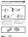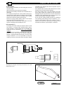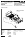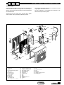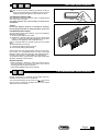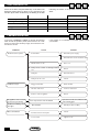
1
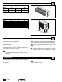
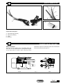
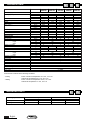
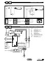
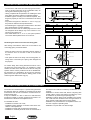
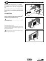
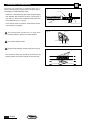
U
CONTENTS
I
A
U
I
A
General recommendations
20
I
A
U
I
A
Basic safety rules
20
I
A
Refrigerant circuits
29
U
I
A
Recommendations
21
I
A
Indoor unit multifilar wiring diagram
29
U
I
A
Range and accessories
21
I
A
Outdoor unit multifilar wiring diagram
30
I
Size and weight
22
I
Indoor/outdoor unit wiring diagrams
30
I
Receiving the product
22
I
Installation
31
I
Handling
22
I
Indoor unit installation
31
I
Quick connector
23
I
Outdoor unit installation
32
A
I
Connection of the units
23
I
A
Condensate drainage
34
I
A
Description of the air-conditioner
26
I
A
Routine maintenance
35
I
A
Technical data
28
U
I
A
Extraordinary maintenance
35
I
A
Operating limits
28
U
I
A
User diagnostics
36
U
U
COMPLIANCE
I
A
DECLARATION OF COMPLIANCE
The company:
DeLonghi S.p.A.
Via L. Seitz, 47
31100 TREVISO ITALY
DECLARES
under its own responsibility that:
the AIR-CONDITIONERS
Range : CF-CP AR
Models : CP 20 ARE 290
CF-CP 30 ARE 290
CF-CP 40 ARE 290
are in conformity with
• Low voltage Directive 73/23EEC,93/68 EEC,
• Electromagnetic compatibility Directive 89/336 EEC and 92/31EEC
The following symbols have been used in some parts of this booklet and inside the appliance:
U
I
A
User
Attention
Installer
Forbidden
After-sales service
Danger: live parts
Danger: moving blades
70°C
Danger: high temperature
Fire hazard
U
GENERAL RECOMMENDATIONS
After having removed the packing, check that the contents are intact and complete. In the event of non-compliance, contact the
the appliance.
Agency which sold you
appliances should be installed by a qualified
company in accordance with the laws and regulations
in force in the country of installation. Upon completion
of work this company should issue the owner the
declaration of compliance of installation with current
regulations and standards and with the instructions
given by
in this booklet.
These appliances have been designed to heat or cool
the air of rooms and should only be used for this purpose in compatibility with their performance characteristics.
Under no circumstances can
be held liable
for damage caused to property or injury to persons or
animals due to incorrect installation, regulation and
maintenance or to improper use.
Too low a temperature is harmful to health as well as
being a useless waste of energy.
Avoid prolonged direct contact with the flow of air.
Avoid the room being closed for a long time.
Periodically open the windows to ensure a correct
change of air.
During storms put the installation on/off switch to "off".
This instruction booklet is an integral part of the
appliance and should therefore be carefully preserved
and ALWAYS accompany the appliance, also in the
event of transfer to another owner or user or into
another installation.
Should the booklet be damaged or lost, request a
copy from the
Area Service Centre.
Repair or maintenance work must be carried out by
the
Service Centre or by qualified personnel
in accordance with instructions given in this booklet.
Do not alter or tamper with the appliance, since hazardous situations could be created and the manufacturer
A
of the appliance will not be liable for any damage or
injury caused.
The unit should be installed in compliance with local
installation and safety regulations.
For any repairs, contact only customer service centres
authorised by the manufacturer. Repairs made by
unauthorised personnel may be dangerous.
The CP20 ARE 290 air conditioner must be used and
stored in rooms with a volume of over 31 cubic
metres.
The CP30-CF30 ARE 290 air conditioner must be
used and stored in rooms with a volume of over 53
cubic metres.
The CF40 ARE 290 air conditioner must be used and
stored in rooms with a volume of over 53 cubic
metres.
Non-ventilated environments where an appliance containing flammable refrigerant is used must be compatible, to avoid the possibility of a gas leak reaching a
level of concentration such as to cause a fire or explosion resulting from the presence of other heat sources
(electric heaters, stoves or similar units).
The R 290 refrigerant charge is highly flammable, and
could cause an explosion in the event of leaks occurring in closed or poorly-ventilated areas. This gas is
heavier than air and invisible, but it generates a mist if
there is humidity in the air.
Avoid contact of the liquefied gas with eyes or skin as
it could cause injuries.
Transportation, charging, cleaning, recovery and disposal of the refrigerant should be carried out only by
customer service centres authorised by the manufacturer.
Disposal of the appliance should be carried out only by
specialised personnel authorised by the manufacturer.
U
BASIC SAFETY RULES
Using electrically-operated products implies the observance
of certain basic safety rules, such as those given below:
I
I
A
ted to the air-conditioner, even if disconnected from the
mains electricity supply.
Do not sit or stand on the appliance or rest anything at
Children and unassisted handicapped persons are not
all on top of it.
allowed to use the air-conditioner.
Do not spray or throw water directly onto the air-condi-
Do not touch the air-conditioner when barefoot or parts
tioner.
of the body are wet or damp.
Do not introduce sharp, pointed objects through the air
Do not carry out any cleaning operation until the air-
intake or outlet grilles
conditioner has been disconnected from the mains
Do not access internal parts of the air-conditioner
electricity supply by putting the installation on/off swit-
without having first put the on/off switch to "off".
ch to "off".
Do not leave the packing material (cardboard, staples,
Do not alter the safety or regulating devices without the
plastic bags, etc.) within reach of children, but dispose
permission and instructions of the manufacturer of the
of properly since it is a potential source of danger.
air-conditioner.
Do not pull, detach or twist the electric cables connec-
English
U
I
A
RECOMMENDATIONS
Extraordinary maintenance
Programmed maintenance always represents a saving in
the running of the installation as well as preventing possible
faults.
To ensure trouble-free operation of the air-conditioner, it is
recommended that it be inspected at least once a year,
carrying out the following checks:
- cleanliness of the heat exchange coils of both units
Exposure control/personal protection
Use protective clothes and suitable gloves; protect eyes and
face.
Handling
Avoid inhaling high concentrations of vapors.
The atmospheric concentrations should be reduced to a
minimum and kept below the professional exposure limit.
The vapors are heavier than air and high concentrations
may therefore form near to the ground, where general ventilation is poor. Under such circumstances, ensure there is
adequate ventilation.
Avoid contact with naked flames and hot surfaces, otherwise
irritating and toxic decomposition products could form. Avoid
the liquid from coming into contact with eyes or skin.
Precautions to take in the event of accidental spillage
Ensure adequate personal protection (using protective
breathing equipment) during elimination of spillage. If conditions are sufficiently safe, isolate the source of the leak. With
small leaks or spills and provided there is adequate ventilation, let the material evaporate. With copious leaks or spills,
adequately ventilate the area; keep the material from expanding using sand, earth or other suitable absorbent material.
Prevent the liquid from entering into drains, sewers, cellars
or work holes, since the vapors could create a suffocating
atmosphere.
First aid measures
Inhalation
- Remove the casualty from the area of exposure and
keep him/her warm and still.
Ask for immediate medical aid.
Contact with the skin
- Thaw the involved parts with water. Remove contaminated clothes, which could stick to the skin in the event of
cold burns. In the event of contact with the skin, immediately rinse with abundant lukewarm water. Should
there be symptoms of irritation or blisters, ask for medical aid.
Contact with the eyes
- Bathe immediately with an eyewash solution or clean
water, keeping the eyelids wide apart for at least ten
minutes. Ask for medical aid.
Swallowing
- Do not provoke vomiting. If the casualty is conscious,
make him/her rinse out his/her mouth with water and
drink 200-300 ml of water. Ask for immediate medical
aid.
Other medical care
- Symptomatic and back-up treatment as required. Do not
administer adrenaline or similar sympathomimetic medicines following exposure, due to the risk of cardiac
arrhythmia.
ATTENTION
For further information on the characteristics of the refrigerant fluid, refer to the safety data sheets available c/o the
refrigerant manufacturers.
spa cannot be held liable for any errors in this
booklet and reserves the right to alter the specifications of
its products without notice.
U
I
A
ACCESSORY
Condensate drainage pipe ø 16 - 50 m.
Activated carbon filters (1 pc.)
Wall bracket Gold
Wall bracket Silver
Condensate drain pump
RANGE AND ACCESSORIES
Model
Code
20÷30
20÷30
20÷30
552626
552929
552632
5572002700
552627 M
English
I
SIZE AND WEIGHT
INDOOR UNIT
Model
L
H
P
Weight
20
810
300
195
9
30
810
300
195
9
40
967
300
195
11
L
H
P
OUTDOOR UNIT
Model
L
H
P
Weight
A
B
20
660
500
230
34
420
264
30
660
500
230
35
420
264
L
40
800
640
280
52
550
310
H
P
A
RECEIVING THE PRODUCT
The air-conditioner comes in two packs protected by cardboard packaging and is accompanied by:
- Instruction booklets for the user and the installer.
- Warranty certificate.
- Bar code labels.
- Supplied accessories, which are contained in a plastic bag
to be found inside the indoor unit pack.
The instruction booklets are an integral part of the airconditioner and should therefore be carefully read and
preserved.
HANDLING
The air-conditioner should be handled by suitably equipped
personnel using equipment that is suitable for the weight of
the appliance.
English
B
I
It is advisable to remove the packing only when the airconditioner has been located in the point of installation.
Carefully remove the adhesive strips positioned on the
air-conditioner
Packaging components must be disposed of correctly
and not left within reach of children since they are a
potential source of danger.
I
During transportation the outdoor unit must be kept in
an UPRIGHT position.
I
QUICK CONNECTOR
Components description
A.
B.
C.
D.
Liquid line (high pressure)
Vapor (low pressure)
Cover
Electrical
I
CONNECTION OF THE UNIT
BASIC OPERATION
The fast connector coupling uses a retractable sleeve and
stem valve on the female half and a spring loaded poppet
on the male side to create a safe, clean and quick
Female
separation of split air condotioning system with minimal fluid
loss and air inclusion (see Figure 1).
Fig. 1
Male
English
I
CONNECTION OF THE UNIT
No tools are required to connect the coupling: a retractable
sleeve and four latch pins hold the male and female halves
together. The coupling valves open when the handle is
pushed forward and locked into place, and shut when the
handle is in the “full back” position (see figures 3-4).
Fig. 2
Fig. 3
Fig. 4
TO CONNECT
- With the coupling handle in the “full back” position (Figure
5), retract the release sleeve on the female and insert the
male half into the coupling. Make sure the insertion tab on
the male half lines up with the slot on the female body (see
Figure 5).
- Realease the retractable sleeve to lock the halves together
and tug gently on the halves to ensure locking has taken
place (Figure 3).
- Rotate the coupling handle towards the male half to open
the coupling. Make sure the handle bottoms on the
Fig. 5
English
coupling body and the locking pin (on models equipped
with spring loaded locking pins) “pops” into the handle hole
properly (see Figure 4).
- Connect the auxiliary electrical and condensate lines, if
applicable.
- Connect the male and female caps together, if provided,
to keep them clean while the unit is in operation and they
are disconnected from their appropriate halves.
- Connect unit to power outlet and start the unit.
I
CONNECTION OF THE UNIT
TO DISCONNECT
- Shut off the air conditioning unit and unplug the unit from
the power outlet.
- Wait five minutes for line pressures to equalize.
- Disconnect the auxiliary electrical and condensate lines, if
applicable.
- On couplings equipped with spring loaded locking pins,
depress the pin until it clears the coupling handle is pulled
up. When the handle clears the locking pin, pull coupling
handle to its “full back” position (see Figure 3).
- Retract the spring loaded release sleeve on the female
and remove the male half (see Figure 5).
- Install the caps on both halves, if provided. Close the
handle on female half after installing the cap.
immediatly upon disconnection with the optional caps as
shows in Figures 6 & 7.
- Don’t tamper with the valves while disconnected or allow
children access to disconnected couplings.
- Don’t drop coupling half on any hard surfaces. The male
half is made of brass and if allowed to drop may become
damaged beyond the point where it can be reconnected.
Installing caps immediatly after disconnection will
minimize the possibility of damage if dropped.
- Do not open the coupling handle while the air conditioning
unit is operating. After shutting off the air conditioning u n i t ,
wait five minutes before opening the coupling in order to
equalize line pressures. Opening the coupling during
airconditioner operation may damage the compressor.
DO’S AND DON’T’S
- Thoroughly check the coupling for proper position of seal
(see Figure 1), missing seals, leaking valves, debris,
proper mounting, or other damage prior to reinstalling and
restarting the air conditioner. Don’t use a damaged
coupling.
- Always keep the couplings connected even when the
system is not in use in order to minimize refrigerant
effusion, coupling damage and the entry of dirt or other
foreign material. If it is not possible to keep the
couplings connected, then both halves should be capped
Fig. 7
Fig. 6
The length of the pipe connecting the internal unit to the
external one is 4 m.
English
U
DESCRIPTION OF THE AIR-CONDITIONER
I
A
alternating current; it ensures high performance, efficiency
and low noise operation.
The speed may be changed according to needs. The heat
exchanger has a large surface area and consists of scored
copper pipes and swirl-type aluminium fins.
Regulation, control of functions, data interchange with the
outdoor unit and diagnostics are governed by a microprocessor card.
The
air-conditioner is an appliance designed for
small user systems. It consists of an indoor unit for wall
mounting and an outdoor unit.
REMOTE CONTROL
The infrared remote control is used for function control, regulation and programming; its operating modes and use are
described in the user booklet.
INDOOR UNIT
The indoor unit housing is plastic.
The electric fan unit consists of a tangential fan powered by
1
CF 20 ARE 290 / CF-CP 30 ARE 290
CF-CP 40 ARE 290
45
2
3
6
4
8
7
9
25
10
22
5
11
12
26 27
24
13
28
31
30
29
14
22
32
33
34
23
36
35
15
41
44
42
47
46
1
2
3
4
5
6
7
8
9
10
11
12
13
14
Wall-mounting plate
Indoor unit base
Indoor fan motor
Sensor unit
Room sensor support
Card support box
Noise filter
Fan capacitor + transformer
Electronic card
Cover
Mode push button
Cover
Sticker
Air filter
English
15
16
17
18
19
20
21
22
23
24
25
26
27
28
Air filter
Flaps motor l.h. shell
Flaps motor r.h. shell
Flap gear
Flap gear
Flap gear
Flap motor
Receiver-led card
Tamperproof grille
Fan support
Fixing angle bracket
Fan rubber grommet
Plastic fan bushing
Fan
29
30
31
32
33
34
35
36
37
38
39
40
41
Drain pipe
Finned coil
Flaps connecting rod/intermediate control
Vertical flaps
Condensate collecting tray
Remote control
White cowl
Logo tab
Bushing
Bushing
Lower louver
Upper louver
Front grille
42
43
44
45
46
47
Strip
Bushing
Louver
Pipe fixing bracket
Quick male coupling
Connection tube
U
I
A
DESCRIPTION OF THE AIR-CONDITIONER
OUTDOOR UNIT
The high efficiency sliding-vane compressor is on double vibration-isolation flexible mountings and is activated by an
electric motor powered by alternating current and fitted with
an overload cutout.
The large surface area exchange coil consists of scored
copper pipes and aluminium fins.
The air-conditioner is commanded and controlled by an
electronic microprocessor system.
The electric fan unit consists of an axial flow fan in plastic
and an electric motor powered by alternating current.
103
110
105
112
134
102
100
109
108
111
106
107
111
104
101
113
114
115
132
133
118
116
117
119
121
122
128
129
125
123
127
124
120
126
130
131
100
101
102
103
104
105
106
107
108
109
110
111
111
Right handle
Left handle
Filter
Fan breakaway starting capacitor
Compressor
Compressor cap.
Compr. protection
Compr. gasket
Compr. cap
4-way valve coil
4-way valve
Pipe closing panel
Pipe closing panel + r.h. handle
112
113
114
115
116
117
118
119
120
121
122
123
124
125
Cable clamp
Compressor insulated cover
Compressor insulated cowl
Quick female coupling
Lower rubber plug
Upper rubber plug
Fan support
Fan flow nozzle
Back
Base
Metal foot
Vibration isolation foot
Finned coil
Plug
126
127
128
129
130
131
132
133
Condensate drainage union
Fan
Fan shock-absorber
Front
Front grille
Spring
Vibration-damping grommet
Insulating cowl
English
U
TECHNICAL DATA
CP 20
ARE 290
V/f/Hz
Btu/h
W
Kcal/h
W
A
Power supply
Cooling capacity
Consumption
Current requirement
E.E.R.
Dehumidifying
Heat output
A
CP 30
ARE 290
CF 40
ARE 290
CP 40
ARE 290
230/1/50
12000
3500
3020
1050
5,7
3.20
1.5
12000
3530
3030
1055
6
3.34
420
17000
5000
4310
1650
7.6
3.03
2.2
600
16320
4800
4137
1570
7.6
3.0
1.9
19720
5800
5000
1860
8.1
3.11
600
650
37
650
37
8013
2350
2025
740
3.9
3.18
1.3
8422
2470
2130
690
3.5
3.57
200
12000
3520
3035
1090
5.7
3.23
1.5
420
m3/h
dB(A)
mm
mm
mm
kg
450
35
550
36
810
300
195
9
580
36
9
11
11
m3/h
dB(A)
mm
mm
mm
kg
1350
4
1400
45
660
500
230
35
1600
46
2100
46
2500
47
l/h
Btu/h
W
Kcal/h
W
A
Consumption
Current requirement
C.O.P.
Quantity of R290 refrigerant
INDOOR UNIT
Air flow
Sound level
Size:
length
height
depth
Indoor unit weight
OUTDOOR UNIT
Air flow
Sound leve
Size:
length
height
depth
Outdoor unit weight
SPECIFICATIONS
Thermostat
Timer
Electronic defroster
LCD remote control
Microcomputer
Electronic diagnostics
Automatic night function
Fan speed
CF 30
ARE 290
I
g
8
35
967
300
195
800
640
280
35
51
52
•
•
•
•
•
•
•
3 + silent
Performance is referred to the following conditions::
- Cooling
- Heating
indoor unit inlet air temperature 27°C d.b., 19°C w.b.
external air temperature 35°C d.b., 24°C w.b.
indoor unit inlet air temperature 20 d.b., 15°C w.b.
external air temperature 7°C d.b., 6°C w.b.
I
OPERATING LIMITS
Operating cycle
Cooling
Heating
English
Room air temperature
MIN
MAX
32°C d.b./23°C w.b.
21°C d.b..16°C w.b.
15°C d.b.
27°C d.b.
External air temperature
MIN
MAX
-10°C d.b.
43° C d.b.
-10°C w.b.
18°C w.b.
A
I
A
REFRIGERANT CIRCUITS
Heating/Cooling
Cooling
HEATING
COOLING
Legend
Condenser
coil
Cooler coil
General filter
Throttling part (capillary)
Quick coupling
Compressor
I
A
Check valve
INDOOR UNIT MULTIFILAR WIRING DIAGRAM
BLUE
YELLOW
BLACK
BLACK
TC1
RED
A2
123456
GREEN
WHITE
BLUE
VIOLET
VIOLET
VIOLET
VIOLET
VIOLET
WHITE
BLUE
VIOLET
SB1
SW
IR
12VAC
HALL
BLACK
WHITE
RED
BLUE
VIOLET
WHITE
WHITE
BLUE
VIOLET
VIOLET
VIOLET
VIOLET
VIOLET
M1
ID1
1 2 3
FLAPS
BLUE
PINK
YELLOW
ORANGE
RED
XS1
BLUE
BLACK
BROWN
BLUE
BLACK
BLACK
ID2
M2
XS2
ST2 ST1
RED
9
8
7
6
5
4
3
2
1
+5V
HALL
WHITE
SENSOR
OUT
BLACK
KA1
Unit power card
Infrared receiver and leds card
EMC noise filter
Room temperature sensor
Exchanger temperature sensor
Compressor relay
Indoor fan motor
Stepping motor for flap
Manual operation key
Transformer for card power supply
Transformer power supply connector
Motor M1 power supply connector
Quick connector
Power supply terminal board
3 2 1
3 2 1
1 2 3
BT2
LEGEND
A1
=
A2
=
A3
=
BT1
=
BT2
=
KA1
=
M1
=
M2
=
SB1
=
TC1
=
XP1-XS1 =
XS2-XP2 =
XS3
=
XT1
=
XP2
XP1
BT1
Reversing
valve
PUMP
AUX 1
4 WAY
IN F
OUT F
L
L-FUS
BROWN
BLACK
ORANGE
BROWN
BLACK
L
L
RED
PT
A1
(1) BLUE
BLUE
(3) BROWN LINE
C
FAN MOTOR
A3
(2) BLACK
BROWN
POWER SUPPLY
2
1
N
BROWN
BROWN
4
3
2
1
XT1
BLUE
YE-GR
3
BLUE
BLUE
YE-GR
YE-GR
XS3
English
I
OUTDOOR UNIT MULTIFILAR WIRING DIAGRAM
A
(1) Cooling only model
XS1
Z1
FR1
4
C
XS1
2
4
M1
C2
M
2
BLUE
1
C1
S
RED
FR1
Z1
1
R
BLACK
C
S
M1
R
3
XT2
YELLOW/GREEN
6
3
YELLOW/GREEN
BROWN
C2
5
C1
BROWN
BLACK
6
BROWN
1
2
3
BLUE
5
BLACK
YELLOW/GREEN
XT2
6
5
4
(2) Heat pump model
C
S
4
RED
FR1
FR1
2
4
BLACK
1
M1
3
C
2
XT2
YELLOW/GREEN
YELLOW/GREEN
YB1
5
Z1
BROWN
C2
M1
YB1
M
C1
6
C2
1
C1
S
BROWN
BLACK
R
BLACK
BROWN
3
BLACK
BLUE
YELLOW/GREEN
6
5
XT2
1
2
3
3
N
6
7
=
=
=
=
=
=
=
=
R
BLACK
XS1
XS1
Z1
6-way female connector
(front view)
Compressor power supply
Fan motor power supply
(1) N.C. (free)
(2) Command line reversing valve
Neutral
Earth
N.C. (free)
N.C. (free)
XS1
FR1
Z1
C1
M1
C2
XT2
YB1
=
=
=
=
=
=
=
=
Female connector
Overload cutout (compressor))
Compressor
Compressor start and run capacitor
Fan motor
M1 capacitor start and run
Terminal board for earth
Reversing valve
INDOOR/OUTDOOR UNIT WIRING DIAGRAMS
Cooling/Heating
Indoor
unit
Unit‡
interna
N
3
2
Outdoor
unit
Unit‡ esterna
English
1
I
A
I
INSTALLATION
The place of installation should be established by the installation designer or by a technically competent person and
should take into account technical requirements as well as
relevant current laws and regulations, which envisage the
obtaining of specific permits (e.g. town-planning, architectural, fire, environmental pollution regulations, etc.); it is therefore advisable to apply for and obtain the necessary permits prior to installing the air-conditioner.
I
The air-conditioner should be installed by a qualified company in accordance with relevant laws and regulations in
force in the country of installation.
Before commencing installation, establish the position of the
indoor and the outdoor unit, taking into consideration the
minimum technical spaces, maximum length of the refrigerant lines and the difference in level between the appliances.
INSTALLATION OF THE INDOOR UNIT
The indoor unit should be wall-mounted.
It should be positioned so that the treated air may circulate
freely throughout the whole room, while observing the mini-
NO
y;y;y;y;y;y;y;y;y;y;
y
;
y;y;y;y;y;y;y;y;y;y;y;y;
y;y;y;y;y;y;y;y;y;y;y;y;
y;y;y;y;y;y;y;y;y;y;y;y;
y; y; y; y; y;
y;y;y;y;y;y;y;y;y;y;
y
;
y;y;y;y;y;y;y;y;y;y;y;y;
y;y;y;y;y;y;y;y;y;y;y;y;
y;y;y;y;y;y;y;y;y;y;y;y;
y
y
y
y
y
;
;
;
;
;
y
y
y
y
y
y
;
;
;
;
;
;
y;y;y;y;y;y;y;y;y;y;y;y;
y;y;y;y;y;y;y;y;y;y;y;y;
y;y;y;y;y;y;y;y;y;y;y;y;
y;y;y;y;y;y;y;y;y;y;y;y;
y;y;y;y;y;y;y;y;y;y;y;y;
YES
mum spaces necessary for technical and maintenance operations.
50 mm
50 mm
50 mm
Recommended installation height is between 1.80 and 2.40 m from the ground.
Water connections
Prior to installing the air-conditioner, decide the direction of
the outlet pipes; they may be arranged in any of the five
directions indicated in Fig.(8):
1. to rear right
2. to right
3. downwards
4. to left
5. to rear left
Fig. 8
4
2
1
3
5
Positioning the fixing plate
Fig. 9
L
21 mm
102 mm
H
102 mm
A
- Remove the steel fixing plate on the unit back
- Rest the cardboard reference template, supplied in the kit,
against the wall
- Position the steel fixing plate in the area outlined by the
cardboard reference template
- Make sure the steel fixing plate is level, using a spirit level
or a plumb line
- Secure the steel fixing plate using the 5 screw anchors
and relative screws provided in the kit
- Should the refrigerant, electrical and condensate drainage
lines exit from the rear in direction “1” or “5”, make the
hole in the wall using a ø 68 mm bit, complying with the
distances indicated in the figure to the side Fig. (9).
86 mm
B
80 mm
Steel plate
B
Overall dimensions
Cardboard template
English
I
INSTALLATION OF THE INDOOR UNIT
- The hole in the wall should be made sloping downwards in
order to aid the natural flow of the condensate water, observing the indications given in Fig.(11).
- Having completed all the operations for installing the steel
fixing plate, remove the reference cardboard template.
- Position the pipes according to the direction required, bending them properly in order not to cause kinks in the actual
pipes.
- To position the pipes for directions “1” and “2” Fig.(10),
they must be rotated to the required direction.
- Avoid bending the copper pipes several times in the same
point, otherwise they could be damaged.
- Remove the unions and the rubber plugs from the indoor
unit refrigerant circuit fittings only at the moment of connecting to the outdoor unit.
- If the outlet direction is “2”, “3” or “4”, use a pair of pliers to
remove the relative plastic knock-out on the unit.
Fig. 10
2
4
1
Model
L
H
A
B
Fig. 11
3
5
20
810
300
52
85
30
810
300
40
138
40
967
300
40
138
y
;
;
y
;
y
y;y;y;y;y;
2 ~ 5 mm
;;;;;;
;;;;;;
;;;;;;
Positioning the indoor unit on the steel fixing plate
After having connected the indoor unit to the outdoor unit
connecting pipes, proceed as follows:
Fig. 12
- Attach the indoor unit to the steel fixing plate by means of
the relative slots on the back of the air-conditioner
Fig.(12).
Attach here
Attach here
- Then press the indoor unit firmly onto the fixing plate, ensuring that it is secured by the spring catch designed for
the purpose.
For further safety, after having attached the indoor unit to
the previously fixed steel plate, it is advisable to make
another two holes in the wall and secure the unit using the
spacers and the screws provided in the kit. To facilitate drilling operations, it is advisable to fix the unit onto the fixing
plate, lift the front part and mark the drilling points on the
wall through the relative holes. Fig.(13).
Fig. 13
Spacer
Screw
ø 6 mm screw anchors
I
INSTALLATION OF THE OUTDOOR UNIT
The outdoor unit should be put in a position that guarantees
the minimum space for sufficient air circulation and to allow
maintenance work and the connections of electrical and refrigerant circuit lines.
It may be installed on a floor or flat roof or wall-mounted,
provided its weight is properly supported and there is no
transmission of vibration to the adjacent rooms.
It is advisable to avoid:
- installation in cavities or air vents;
- installation where obstacles or barriers could cause recirculation of the expelled air;
- installation in places with an aggressive atmosphere;
- installation in confined places in which the sound level of
English
-
-
-
the outdoor unit could be increased by reverberation or resonance;
installation in corners where dust, leaves or anything else
usually collects, which could reduce the efficiency of the
air-conditioner by obstructing the passage of air;
installation in places where the air expelled by the outdoor
unit could enter the inhabited rooms through windows or
doors, thereby causing discomfort to those inside;
installation in a place where the air expelled from the outdoor unit is against a prevailing wind;
installation in a place that is in direct sunlight.
I
Installation of the outdoor unit drain line (if available)
INSTALLATION OF THE OUTOOR UNIT
Fig. 14
A
During operation in the heating mode, the condensate water
may be drained from the outdoor unit through three drain
holes.
Insert the drain male fitting into the hole where drainage of
the condensate water is required and plug the remaining
two holes using the plugs B supplied in the kit, as shown in
Fig.(14).
B
C
FLOOR INSTALLATION
D
Installation on a floor or flat roof does not necessitate fixing
the feet to the floor. The feet should instead be placed on
supports (~70÷80 mm) to allow application of the condensate drain line (for units with heat pump only).
Fig. 15
10
0m
m
The minimum distances shown in the figure should be
observed. Fig.(15).
200
0m
SUSPENDED INSTALLATION
m
The minimum spaces indicated should be observed for
suspended installation, which requires a support kit that
must be ordered separately.
Carefully check the structure and the capacity load of
the supporting wall. Fig.(16).
mm
10
100
mm
Fig. 16
English
I
;
;
;
;; ; ; ;;;
The indoor unit is fitted with a condensate drain pipe, to
which a drainage hose (ø inside 16 mm) should be connected leading to a suitable drainage outlet.
Fig. 17
Protection
- Fasten the condensate drain pipe to the refrigerant pipes
with adhesive tape whenever the lines cross through a
wall; this is to prevent the condensate drain pipes from
being flattened. Fig.(17) - Fig.(18).
- In the summer mode of operation, check that the condensate is flowing out regularly.
Drain pipe
Drain pipe extension
Fig. 18
The drainage pipe should have a 2° slope down
towards the drain; it should never slope upwards.
;;;;
CONDENSATE DRAINAGE
Pipework
;;;;;;;
;;;;;;;
;;;;;;;
;;;;;;;
;;;;;;;
;;;;;;;
Installation place
Check all the joints for leaks.
Drain pipe
Power supply cable
- The condensate drain pipe should be inserted onto the
coupling located on the bottom left part of the indoor unit.
English
Fig. 19
Insulating tape
y;yy;;y;y;y;y;yy;;y;y;y;
y;y;yy;;yy;;y;yy;;yy;;y;yy;;yy;;y;yy;;
y;y;yy;;yy;;y;yy;;yy;;y;yy;;yy;;y;yy;;
y;y;yyy;;;yy;;y;yyy;;;yy;;y;yyy;;;yy;;y;yyy;;;
y;y;y;yy;;y;yy;;yy;;y;yy;;yy;;y;y;
Apply thermal insulating material to the joints. Fig.(19).
U
I
A
ROUTINE MAINTENANCE
ON
Do not carry out any cleaning operations until you
have disconnected the air conditioner from the power
supply by setting the system’s main switch to “OFF”.
CLEANING THE INDOOR UNIT
The appliance should be cleaned using a slightly damp
cloth. Dry it with a dry cloth.
For safety reasons, do not use water to clean the air
conditioner.
Caution
Do not use gasoline, alcohol or solvents for cleaning.
Do not spray insecticide or similar products on the unit.
CLEANING THE AIR FILTERS
To ensure the long life and efficiency of your air conditioner
follow these instructions:
1. Clean the dust filter once a week.
2. Replace the purifying filter (if any) at the end of each
season, or when it is exhausted (follow the instructions
posted on the appliance next to the filter seat).
The air purifying filters are located under the front intake
grille.
To clean the filters you need to:
1. Lift the front grille as shown in fig. 20.
2. Remove the purifying filter (black).
Remove the dust from the dust filter using a vacuum cleaner. If there is a considerable amount of dust, wash with
lukewarm water and rinse thoroughly. The water temperature must not exceed 40°C. After washing, let the filter dry.
To reinstall the filters, replace them in the filter holder, then
reposition the latter in the machine.
OFF
Fig. 20
;;
yy
;;;
;;;
yyy
;yyy
;
yy
;;;
;;;
;;;
yyy
yyy
yyy
;;;
yyy
;;
;;
yy
yy
;;;
;;
;;
;;;
;;;
yyy
yy
yy
yyy
yyy
;;;
;;;
;;
yyy
yyy
yy
;;
;;;
yy
yyy
;;;
;;
;;;
;;
;;
;;
yyy
yy
yyy
yy
yy
;;yyy
;;;
;; yy
yy
;;yy
;;;
;;yy
yyy
yy
;;
;;;yy
;;yy
yyy
;;;
;;
yyy
yy
;;;
yyy
SEASON CHECKS
- Before starting the appliance, make sure that the power
cord and outlet are in perfect condition and that the
earthing/grounding system is efficient.
- Follow the installation instructions carefully.
I
A
EXTRAORDINARY MAINTENANCE
Periodic maintenance is essential for the safety, efficiency,
reliability and long-life of the air-conditioner.
This may be periodically carried out by the
Service
Centre, which is technically prepared and also has original
spare parts when necessary.
English
U
USER DIAGNOSTICS
If there is an alarm, keep the MODE key on the indoor unit
keyboard pressed down for about 4 sec. and wait for the
acoustic signal, which is followed by the blinking of the leds
I
indicating the nature of the problem connected with the
alarm.
Room temp. sensor fault
ON
OFF
OFF
Coil temp. sensor fault
OFF
ON
OFF
Appliance empty
ON
ON
OFF
Condensate drain pump fault
ON
OFF
ON
High pressure switch fault
OFF
ON
ON
Fan fault
ON
ON
ON
U
TROUBLESHOOTING
In the event of problems or failure, go through the following
table. Should the problem persist, disconnect the air-conditioner from the mains electricity supply and contact the nearest Service Centre.
PROBLEM
The fan does not operate
A
I
A
If the problem is not indicated in the table, please contact
your installer.
CAUSE
Power failure
REMEDY
Check the power supply
Check the fuse on the electronic card
On/off switch on "off"
Put to "on”
Faulty remote control or discharged batteries
Check
Faulty fan
Check fan motor
Faulty electronic card
Insufficient output
The appliance does not work
for about 3' upon starting
Simultaneous blinking of indicator lights
Noise and vibration
Check
Clogged mesh filter
Clean the filter
Air flow obstructed
Remove obstruction
Remote control regulation
Check
Form of protection of the mechanism
Just wait 3' and the air-conditioner will
start working again
General failure
Check (see user booklet)
Contact between metal parts
Check
Loose screws
Tighten screws