1
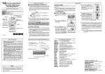
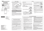
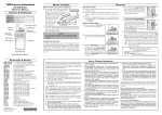
CONTROLS & CONNECTORS (4 KEY)
VX-420A Series (LTR)
Operating Manual
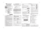
CONTROLS & CONNECTORS (16 KEY)
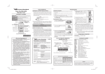
LED INDICATOR LTR
Glows Green
Blinking Green
Glows Red
Blinking Red
Yellow
LED INDICATOR LTR
Glows Green
Blinking Green
Glows Red
Blinking Red
Yellow
CONVENTIONAL
System Busy
--Transmitting
Battery Voltage is low
Receiving a Selective Call
Monitor on
Busy Channel (or SQL off)
Transmitting
Battery Voltage is low
Receiving a Selective Call
CONVENTIONAL
System Busy
--Transmitting
Battery Voltage is low
Receiving a Selective Call
Monitor on
Busy Channel (or SQL off)
Transmitting
Battery Voltage is low
Receiving a Selective Call
System/Group Selector
Antenna
VOL/PWR Knob
Push To Talk
(PTT) Switch
Side 1 Switch
Speaker
Side 2 Switch
LCD
Microphone
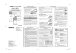
Ì To install the battery, hold the transceiver with your left hand, so
your palm is over the speaker and your thumb is on the top of the
belt clip. Insert the battery pack into the battery compartment on
the back of the radio while tilting the Belt Clip outward, then close
the Battery Pack Latch until it locks in place with a “Click.”
he
Tilt t
Belt
Clip
Insert the Battery Pack
Close the Battery Pack Latch
MIC/SP Jack
(External Mic/Earphone)
Microphone
MIC/SP Jack
(External Mic/Earphone)
Battery Pack Installation and Removal
System/Group Selector
Antenna
VOL/PWR Knob
Push To Talk
(PTT) Switch
OPERATION
BEFORE YOU BEGIN
Ì To remove the battery, turn the radio off and remove any protective
cases. Open the Battery Pack latch on the bottom of the radio, then
slide the battery downward and out from the radio while holding
the Belt Clip.
4 KEY
Caution!
Preliminary Steps
Ì Install a charged battery pack onto the transceiver, as described
previously.
Ì Screw the supplied antenna onto the Antenna jack. Never attempt
to operate this transceiver without an antenna connected.
Ì If you have a Speaker/Microphone, we recommend that it not be
connected until you are familiar with the basic operation of the
VX-420A Series (LTR).
Operation Quick Start
Ì Turn the top panel’s VOL/PWR knob
clockwise to turn on the radio on.
Ì Turn the top panel’s System/Group selector knob to choose the desired operating channel.
Do not attempt to open any of the rechargeable Ni-Cd packs, as
they could explode if accidentally short-circuited.
Side 1 Switch
Speaker
Side 2 Switch
LCD
Battery Pack Latch
16 KEY
Battery Pack Latch
E C 0 7 1 U 1 0 3
SAFETY TRANING INFORMATION
This Radio has been tested and complies with the Federal Communications Commission (FCC) RF exposure limits for Occupational Use/
Controlled exposure environment. In addition, it complies with the
following Standards and Guidelines:
Ì FCC 96-326, Guidelines for Evaluating the Environmental Effects
of Radio-Frequency Radiation.
Ì FCC OET Bulletin 65 Edition 97-01 (1997) Supplement C, Evaluating Compliance with FCC Guidelines for Human Exposure to
Radio Frequency Electromagnetic Fields.
Ì ANSI/IEEE C95.1-1992, IEEE Standard for Safety Levels with
Respect to Human Exposure to Radio Frequency Electromagnetic
Fields, 3kHz to 300 GHz.
Ì ANSI/IEEE C95.3-1992, IEEE Recommended Practice for the Measurement of Potentially Hazardous Electromagnetic Fields-RF and
Microwave.
WARNING:This radio generates RF electromagnetic energy
during transmit mode. This radio is designed for and classified
as Occupational Use Only, meaning it must be used only during the
course of employment by individuals aware of the hazards, and the
ways to minimize such hazards. This radio is not intended for use by
the General Population in an uncontrolled environment.
CAUTION:To ensure that your expose to RF electromagnetic
energy is within the FCC allowable limits for occupational use,
always adhere to the following guidelines:
H This radio is NOT approved for use by the general population
in an uncontrolled environment. This radio is restricted to occupational use, work related operations only where the radio
operator must have the knowledge to control its RF exposure
conditions.
H When transmitting, hold the radio in a vertical position with
its microphone 1 to 2 inches (2.5 to 5 cm) away from your mouth
and keep the antenna at least 1 inch (2.5cm) away from your
head and body.
H The radio must be used with a maximum operating duty cycle
not exceeding 50 %, in typical Push-to-Talk (PTT) configurations. DO NOT transmit for more than 50 % of total radio use
time (50 % duty cycle). Transmitting more than 50 % of the
time can cause FCC RF exposure compliance requirements to
be exceeded.
The radio is transmitting when the red LED on the top of the
radio is illuminated. You can cause the radio to transmit by
pressing the PTT button or by using the VOX headset, model
VC-25.
H DO NOT transmit when the radio is used in Body Worn configuration with the following accessory: belt-clip.
It must be used ONLY for (1) there is a 4 cm distance from the
body during transmitting, (2) monitoring purposes, using the
speaker only and (3) for carrying purposes.
H Always use Vertex Standard authorized accessories.
Low Battery Indication
Ì As the battery discharges during use, the voltage gradually becomes
lower. When the battery voltage becomes to low, substitute a freshly
charged battery and recharge the depleted pack. The TX/BUSY indicator on the top of the radio will blink red when the battery voltage is low.
Ì Avoid recharging Ni-Cd batteries often with little use between
charges, as this can degrade the charge capacity. We recommend
that you carry an extra, fully-charged pack with you so the operational battery may be used until depletion (this “deep cycling” technique promotes better long-term battery capacity).
DISPLAY ICONS & INDICATORS
“Scan” is activated
“Call” indicator
Low Transmit Power Mode
“ON”
“Encryption” is activated
RSSI Indicator (four steps)
Receiver Monitor
Battery Indicator
Home System/Group is selected
8 Character Alpha-numeric Display
The information listed above provides the user with the information
needed to make him or her aware of RF exposure, and what to do to
assure that this radio operates with the FCC RF exposure limits of this
radio.
Electromagnetic Interference/Compatibility
During transmissions, this radio generates RF energy that can possibly cause interference with other devices or systems. To avoid
such interference, turn off the radio in areas where signs are posted
to do so.
Do not operate the transmitter in areas that are sensitive to electromagnetic radiation such as hospitals, health care facilities, aircraft, and blasting sites.
FCC LICENSE INFORMATION
This radio operates on communications frequencies which are subject to FCC (Federal Communications Commission) Rules and
Regulations. FCC Rules require that all operators using Private
Land Mobile radio frequencies obtain a radio license before operating their equipment.
Ì Rotate the VOL/PWR knob to set the volume level. If no signal is present, press
and hold in the Programmable key assigned to “NSQL” for more than one second; background noise will now be heard,
and you may use this to set the VOL/
PWR knob for the desired audio level.
Ì Press and hold in the Programmable
key assigned to “NSQL” for more than
one second (or press the NSQL key
twice) to quiet the noise and resume normal (quiet) monitoring.
Notice !
There are no owner-serviceable parts inside the transceiver. All
service jobs must be referred to an authorized VERTEX STANDARD Service Representative. Consult your Authorized VERTEX STANDARD Dealer for installation of optional accessories.
This device complies with Part 15 of the FCC rules. Operation is
subject to the condition that this device does not cause harmful
interference.
Ì To transmit, monitor the channel and make sure it is clear.
THIS IS AN FCC REQUIREMENT!
Ì To transmit, press and hold in the PTT
switch. Speak into the microphone area
of the front panel grille (lower left-hand
corner) in a normal voice level. To return to the Receive mode, release the
PTT switch.
Ì If a Speaker/Microphone is available, remove the plastic cap and
its two mounting screws from the right side of the transceiver, then
insert the plug from the Speaker/Microphone into the MIC/SP jack;
secure the plug using the screws supplied with the Speaker/Microphone. Hold the speaker grille up next to your ear while receiving.
To transmit, press the PTT switch on the Speaker/Microphone, just
as you would on the main transceiver’s body.
Note:Save the original plastic cap and its mounting screws. They
should be re-installed when not using the Speaker/Microphone.
Trunking System
Ì Press the PTT switch.
Ì When a channel is available, the TX/BUSY indicator will glow
red. The radio is now transmitting. While holding the PTT switch,
speak into the microphone area of the front panel grille (lower lefthand corner) in a normal voice level.
Ì If all channels are busy, a continuous tone will be heard from the
speaker, and the “BUSY” notation will appear on the display when
the PTT switch is pressed. Release the PTT switch.
Ì If the radio is out of range during the transmitting attempt, slow
beeps will be heard followed by a continuous tone from the speaker.
KEY FUNCTIONS
DESCRIPTION OF OPERATING FUNCTIONS
The VX-420A Series (LTR) provides programmable [A], [B], [C],
] and [
] switches.
[D] function keys and programmable [
These Programmable keys functions can be customized (set to
other functions), via programming by your VERTEX STANDARD
dealer, to meet your communications/network requirements. Some features may require the purchase and installation of optional internal
accessories. The possible Programmable key programming features
are illustrated below, and their functions are explained in the next chapter. For further details, contact your VERTEX STANDARD dealer.
For future reference, check the box next to each function that has been
assigned to the Programmable key on your particular radio, and
keep it handy.
Function
Programmable key (Press/Press and Hold)
[A]
[B]
[C]
[D] [Side 1] [Side 2]
System Up
/
/
/
/
/
/
System Down
/
/
/
/
/
/
Group Up
Group Down
/
/
/
/
/
/
/
/
/
/
/
/
/
--/--
/
--/--
/
--/--
/
--/--
/
--/--
/
--/--
/
/
/
/
/
/
/
/
/
Monitor
NSQ
TX Low Power
Key Lock
/
/
/
Lighting
Scan
/
/
/
/
/
/
/
/
/
/
/
/
Talkaround
/
/
/
/
/
/
Scan A/D
Phone
/
/
/
/
/
/
/
/
/
/
/
/
Call/Reset
/
/
/
/
/
/
Call 1
Call 2
/
/
/
/
/
/
/
/
/
/
/
/
Code Up
Code Down
/
/
/
/
/
/
/
/
/
/
/
/
/
--/--
/
--/--
/
--/--
/
--/--
/
--/--
/
--/--
Code Set
Emergency
Home
/
/
/
/
/
/
Home Set
/
/
/
/
/
/
Short-cut to GP 1
Short-cut to GP 2
/
/
/
/
/
/
/
/
/
/
/
/
Short-cut to GP 3
/
/
/
/
/
/
Continuous System Down
/
--/---/--
/
--/---/--
/
--/---/--
/
--/---/--
/
--/---/--
/
--/---/--
Continuous Group Up
Continuous Group Down
--/---/--
--/---/--
--/---/--
--/---/--
--/---/--
--/---/--
Short-cut to GP 4
Continuous System Up
Copyright 2013
Vertex Standard LMR, Inc.
All rights reserved.
No portion of this manual
may be reproduced
without the permission of
Vertex Standard LMR, Inc.
Printed in China
Vertex Standard LMR, Inc.
System Up, Down
Press (or Press and hold) the assigned Programmable key to switch
to a higher (or lower) System.
Once the desired System is reached, rotate the System/Group knob
to select the desired System/Group within the selected System.
Group Up, Down
Press (or Press and hold) the assigned Programmable key to switch
to a higher (or lower) operating Group number.
Monitor
Press (or Press and hold) the assigned Programmable key to disable
the Signaling Squelch (CTCSS, DCS, 5-Tone Signaling, or DTMF
Pager). Again press (or Press and hold) the assigned Programmable
key to resume normal (quiet) the Signaling Squelch action.
When the Signaling Squelch is disabled, the “ ” icon will be indicated on the display.
NSQ
Press and hold the assigned Programmable key to disable both the
Noise and Signaling Squelch (CTCSS, DCS, 5-Tone Signaling, or DTMF
Pager) systems. Again press and hold the assigned Programmable
key to resume normal (quiet) operation of the Noise and Signaling
Squelch system.
When the Signaling Squelch is disabled, the “ ” icon will be indicated on the display.
TX Low Power
Press (or Press and hold) the assigned Programmable key to set the
radio’s transmitter to the “Low Power” mode, thus extending battery
life. Press (or Press and hold) the assigned Programmable key again
to return to “High Power” operation when in difficult terrain.
When the radio’s transmitter is set to “Low Power” mode, the “L”
icon will be indicated on the display.
Key Lock
Press (or Press and hold) the assigned Programmable key to lock
the Programmable keys (except Lock, Emergency, Monitor, Lighting, and NSQ keys); thus, the [A], [B], [C], and [D] keys can be disabled to prevent radio settings from being disturbed. In the Lock mode,
the display will show “LOCK” when you rotate the System/Group
selector knob or touch a Programmable key.
Lighting
Press (or Press and hold) the assigned Programmable key to illuminate the LCD for five seconds.
Scan
The Scanning feature is used to monitor multiple channels programmed
into the transceiver. While scanning, the radio will check each channel
for the presence of a signal, and will stop on a channel if a signal is
present.
Ì To activate scanning:
Press (or Press and hold) the assigned Programmable key.
The scanner will search the channels, looking for active ones; it
will pause each time it finds a channel on which someone is speaking.
Ì To stop scanning:
Press (or Press and hold) the assigned Programmable key.
Operation will revert to the channel to which the System/Group
knob is set.
Talk Around
Press (or Press and hold) the assigned Programmable key to activate the Talk Around feature when you are operating on duplex channel systems (separate receive and transmit frequencies, utilizing a “repeater” station). The Talk Around feature allows you to bypass the
repeater station and talk directly to a station that is nearby. This feature has no effect when you are operating on “Simplex” channels, where
the receive and transmit frequencies are already the same.
When the “TA” function is activated, the “TA ON” notation will be
appeared on the display.
Note that your dealer may have made provision for “Talk Around”
channels by programming “repeater” and “Talk Around” frequencies
on two adjacent channels. If so, the key may be used for one of the
other Pre-Programmed Functions.
Scan A/D
The Add/Del feature allows the user to arrange a custom Scan.
Press (or Press and hold) the assigned Programmable key to delete/
restore the current channel to/from your scanning list.
When you delete a stored channel, the “ ” icon will, in turn disappear. When you restore a channel, the “ ” icon will now appear.
Phone
Your Dealer may have pre-programmed Auto-Dial telephone number
memories into your radio.
To dial a number, just press (or Press and hold) the Dealer-assigned
Programmable key for Speed Dialing. The DTMF tones sent during the dialing sequence will be heard in the speaker.
ARTS (AUTO RANGE TRANSPOND SYSTEM)
This system is designed to inform you when you and another ARTSequipped station are within communication range.
During ARTS operation, your radio automatically transmits for about
1 second every 25 or 55 seconds in an attempt to shake hands with the
other station.
If you have out of range for more than two minutes, your radio senses
that no signal has been receives, a ringing beeper will sound, and
“GROU OUT” will appear on the LCD. If you subsequently move
back into range, as soon as the other station transmits, your beeper
will sound and “GROU IN” will appear on the LCD.
DTMF PAGING SYSTEM (REQUIRES FVP-25 OPTIONAL BOARD)
This system allows paging and selective calling, using DTMF tone
sequences.
When your radio is paged by a station bearing a tone sequence which
matches yours, your radio’s squelch will open and the alert will sound.
The three-digit code of the station which paged you will be displayed
on your radio’s LCD.
Call/Reset
Press (or Press and hold) the assigned Programmable key to silence
the receiver and reset for another call (when your communication is
finished).
Call 1/Call 2
Press (or Press and hold) the assigned Programmable key to send a
5-tone sequential tone group which is pre-defined.
Call Up/Call Down
Press (or Press and hold) the assigned Programmable key to select a
5-tone encode code from the pre-defined encode list.
Code Set
Press (or Press and hold) the assigned Programmable key to change
the encode digits for 5-tone operation. To change a specific digit, select the desired digit using the [A] key, then change thenumber using
the [B]/[C] keys, and store the number using the [D] key.
Emergency
The VX-420A Series (LTR) includes an “Emergency” feature, which
may be useful, if you have someone monitoring on the same frequency
as your transceiver’s channel. For further details contact your VERTEX STANDARD dealer.
Home
Press (or Press and hold) the assigned Programmable key to recall
the pre-programmed Home system/group. When you recall the Home
system/group, the “H” icon will appear on the display.
Press (or Press and hold) the assigned Programmable key again to
return to previous system/group; the “H” icon will disappear on the
display.
Home Set
Press (or Press and hold) the assigned Programmable key to store
the current system/group to the Home register.
Short-cut GP-1, GP-2, GP-3, GP-4
Press (or Press and hold) the assigned Programmable key to recall
the Dealer pre-programmed System/Group directly.
Continuous System Up, Down
Press and hold the assigned Programmable key causes the radio to
begin stepping (repeatedly) upward or downward through the Systems.
Continuous Group Up, Down
Press and hold the assigned Programmable key causes the radio to
begin stepping (repeatedly) upward or downward through the Groups.
ACCESSORIES & OPTIONS
FNB-V57
FNB-V57IS
FNB-V67LIA
FNB-83
FNB-V94
FBA-25A
VAC-10
VAC-800
VAC-810
VAC-6800
VAC-6810
MH-45B4B
MH-37A4B
VC-25
VCM-1
FVP-25
ATU-6D
ATV-6XL
ATV-8C
CE47
FIF-12
CT-27A
CT-28
CT-29
CT-106
7.2 V 1100 mAh Ni-Cd Battery
Intrinsically-Safe 7.2 V 1100 mAh Ni-Cd Battery
7.4 V 2300 mAh Lithium-Ion Battery
7.2 V 1400 mAh Ni-MH Battery
7.2 V 1800 mAh Ni-MH Battery
Alkaline Battery Case
Desktop Rapid Charger
(for FNB-V57/-V57IS/-83/-V94)
Desktop Rapid Charger (for FNB-V57/-V57IS)
Desktop Rapid Charger (for FNB-V67LIA)
6-unit Multi Charger (for FNB-V57/-V57IS)
6-unit Multi Charger (for FNB-V67LIA)
Speaker/Microphone
Earpiece Microphone
VOX Headset
Mobile Mounting Bracket (for VAC-800/-810)
DTMF pager Unit
Rubber Antenna 450-490 MHz
Untuned Antenna 134-174 MHz
Rubber Antenna 161-174 MHz
Programming Software
USB Programming Interface
Radio to Radio Cloning Cable
Programming Cable (for CT-29)
RS-232C Programming Interface Cable
Programming Cable (for FIF-12)
WARRANTY POLICY
Vertex Standard warrants, to the original purchaser only, its Vertex
Standard manufactured communications products against defects in
materials and workmanship under normal use and service for a given
period of time from the date of purchase.
Limited Warranty Details:
North America customers (USA and Canada):
http://www.vertexstandard.com/lmr/warranty-terms.aspx
Customers outside of North America:
Contact the authorized dealer in your country.