1
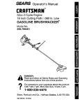
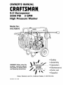
OWNER'S
MANUAL
CRAFTSMAN
®
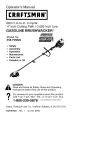
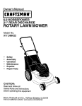
9.0 Horsepower
3000 PSI
3 GPM
High Pressure Washer
Model No:
919.763010
WARNING:
Before using this
product,
read this manual
and follow
all Safety
Rules
and Operating
Instructions.
PRESSURE WASHER
/
CUSTOMER
--HELPLINE
1-800-245-5873
-__
_
•
•
•
....
•
•
Safety
Assembly
Operation
Maintenance
Parts List
• Espa_ol
Sears,
MGP-763010
Rev. 1/15/98
Roebuck
and
Co.,
Hoffman
Estates,
IL 60179
U.S.A.
TABLE OF CONTENTS
Warranty
Safety
............................................
Guidelines
2
..............................
.................................................
Troubleshooting
Parts ................................................
16-33
EPA Codes ......................................
34-35
..........................................
5-7
Operation
..........................................
7-10
......................................
11-13
ONE
YEAR
WARRANTY
....................................
How to Order
Espa5ol
LIMITED
14
3-5
Assembly
Maintenance
Storage
ON CRAFTSMAN
Parts ...............
Back Cover
...........................................
HIGH
PRESSURE
15
35-55
WASHER
For one year from the date of purchase, when this Craftsman High Pressure Washer is maintained and operated according to the instructions in the owner's manual, Sears will repair, free of
charge, any defect in material and workmanship.
If your Craftsman Pressure Washer is used for commercial
applies only for 90 days from the date of purchase.
LIMITED
ONE
YEAR
WARRANTY
or rental purposes, this warranty
ON CRAFTSMAN
ENGINE
For one year from the date of purchase, when this Craftsman engine is maintained and operated
according to the instructions in the owner's manual, Sears will repair, free of charge, any defect
in material and workmanship.
If your Craftsman engine is used for commercial or rental purposes, this warranty applies only
for 90 days from the date of purchase. This warranty does not cover: Expendable items such as
spark plugs and air filters, which become worn during normal use.
Repairs necessary because of operator abuse or negligence, including damage resulting from
no water being supplied to pump or failure to maintain the equipment according to the instructions contained in the owner's manual, are not covered under warranty.
WARRANTY SERVICE IS AVAILABLE BY RETURNING THE HIGH PRESSURE WASHER TO THE
NEAREST SEARS SERVICE CENTER/DEPARTMENT THROUGHOUT THE UNITED STATES.
This, warranty gives you specific legal rights and you may also have other rights, which vary
from state to state.
Sears,
Roebuck
and Co., D/817
WA, Hoffman
Estates,
IL 60179
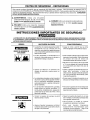
SAFETY
GUIDELINES
- DEFINITIONS
This manual contains information that is important for you to know and understand. This information relates to protecting
YOUR SAFETY and PREVENTING EQUIPMENT PROBLEMS. To help you recognize this information, we use the symbols
below. Please read the manual and pay attention to these sections. SAVETHESE DEFINITIONS/INSTRUCTIONS.
,& WARNING indicates a potentially hazardous
situation which, if not avoided, could result in
death or serious injury.
_, CAUTION indicates a potentially hazardous situation
which, if not avoided, _
result in minor or moderate
_, DANGER indicates an imminently hazardous
situation which, if not avoided, will result in
death or serious injury.
1012/97
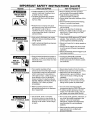
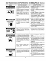
IMPORTANT
SAFETY INSTRUCTIONS
Improper operation or maintenance of this product could result in serious injury and property damage. Read
and understand all warnings and operating instructions before using.
HOW TO PREVENT IT
HAZARD
WHAT CAN HAPPEN
• Shut off engine and allow it to cool
before adding fuel to the tank.
RISK OF EXPLOSION
OR FIRE
Spilled gasoline and its vapors can
become ignited from cigarette
sparks, electrical arcing, exhaust
gases, and hot engine components
such as the muffler.
Heat will expand fuel in the tank
which could result in spillage and
possible fire explosion.
• Use care in filling tank to avoid
spilling fuel. Move pressure washer
away from fueling area before
starting engine.
• Keep maximum fuel level 1/2"below
top of tank to allow for expansion.
Operating the pressure washer in an
explosive environment could result
in a fire.
• Operate and fuel equipment in well
ventilated areas free from obstructions. Equip areas with fire
extinguishers suitable for gasoline
fires.
• Never operate pressure washer in an
area containing dry brush or weeds.
Materials placed against or near the
pressure washer can interfere with
its proper ventilation features
causing overheating and possible
ignition of the materials.
Improperly stored fuel could lead to
accidental ignition. Fuel improperly
secured could get into the hands of
children or other unqualified persons.
• Store fuel in container approved for
gasoline, in a secure location away
from work area.
Breathing exhaust fumes will cause
serious injury or death.
Operate pressure washer in a well
ventilated area. Avoid enclosed areas
such as garages, basements ,etc.
Never operate unit in a location
occupied by humans or animals.
Some cleaning fluids contain substances which could cause injury to
skin, eyes, or lungs.
Use only cleaning fluids specifically
recommended for high pressure
washers. Follow manufacturers
recommendations.
RISK TO BREATHING
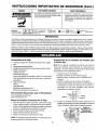
IMPORTANT
SAFETY INSTRUCTIONS
(cont'd)
HAZARD
WHAT CAN HAPPEN
HOW TO PREVENT IT
RISK OF UNSAFE
OPERATION
Unsafe operation of your pressure
washer could lead to serious injury
or death to you or others.
The spray gun/wand is a powerful
cleaning tool that could look like a
toy to a child.
• Become familiarwith the operation
and controls of the pressure washer.
• Keep children away from the
pressure washer at all times.
• Never defeat the safety features of this
product.
• Do not operate machine with missing,
broken, or unauthorized parts.
Reactive force of spray will cause
gun/wand to move, and could cause
the operator to slip or fall, or
misdirect the spray. Improper control
of gun/wand can result in injuries to
self and others.
• Never leave wand unattended while
unit is running.
• Keep work area free of obstacles.
• Stand on a stable surface and grip gun/
wand firmly. Expect the gun to kick
when triggered.
High velocity fluid spray can cause
objects to break, propelling particles
at high speed.
• Always wear ANSI approved Z87 safety
glasses. Wear protective clothing to
protect against accidental spraying.
Light or unsecured objects can become
hazardous projectiles.
• Never point wand at, or spray people or
animals.
• Always secure trigger lock when wand
is not in service to prevent accidental
operation.
• Never permanently secure trigger in pull
back (open) position.
RISK OF INJURY FROM
SPRAY
ELECTRICAL
SHOCK
RISK
OF
Vt_YI;1 ;1_I I _[r]
RISK OF FLUID INJECTION
RISK OF CHEMICAL
BURN
• Spray directed at electrical outlets or
switches, or objects connected to an
electrical circuit, could result in a fatal
electrical shock.
• Unplug any electrically operated
product before attempting to clean it.
Direct spray away from electric outlets
and switches.
• Your washer operates at fluid
pressures and velocities high enough
to penetrate human and animal flesh,
which could result in amputation or
other serious injury. Leaks caused by
loose fittings or worn or damaged
hoses can result in injection injuries.
DO NOT TREAT FLUID INJECTION AS
A SIMPLE CUT! See a physician
immediately!
• Never place hands in front of nozzle.
• Direct spray away from self and others.
• Make sure hose and fittings are
tightened and in good condition. Never
hold onto the hose or fittings during
operation.
• Do not allow hose to contact muffler.
• Neverattach or remove wand or hose
fittings while system is pressurized.
• Relieve system pressure before
attempting maintenance or disassembly of equipment.
• Use only hose and high pressure
accessories rated for 2000 PSI service.
• To relieve system pressure, shut off
engine, turn off water supply, and pull
gun trigger until water stops flowing.
Use of acids, toxic or corrosive
chemicals, poisons, insecticides, or
any kind of flammable solvent with this
product could result in serious injury
or death.
• Do not use acids, gasoline, kerosene, or
any other flammable materials in this
product. Use only household
detergents, cleaners and degreasers
recommended for use in pressure
washers.
• Wear protective clothing to protect
eyes and skin from contact with
sprayed materials.
4
IMPORTANT
SAFETY
INSTRUCTIONS
(cont'd)
HAZARD
WHAT CAN HAPPEN
HOW TO PREVENT IT
RISK OF HOT SURFACES
• Contact with hot surfaces, such as
engines exhaust components, could
result in serious burn.
• During operation, touch only the control
surfaces of the pressure washer. Keep
children away from the pressure washer
at all times. They may not be able to
recognize the hazards of this product.
Symbol,
o*°o,'o
Ma°o ,
I' I o"o"o
IMPORTANT:
The powerful spray from your pressure washer is capable of causing damage to fragile surfaces such as: wood, glass,
automobile paint, auto stripping and trim, and delicate objects such as flowers and shrubs. Before spraying, check the
item to be cleaned to assure yourself that it is robust enough to resist damage from the force of the spray. Avoid the
use of the concentrated spray stream except for very strong surfaces like concrete and steel.
Operating unit with water supply shut off without flow of water will result in equipment damage. You should never run
this pressure washer for more than 2 minutes without pulling the trigger to allow cool water to enter the pump and the
heated (recirculated) water to exit. Running the pressure washer with water supply shut off will void your warranty.
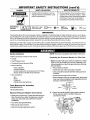
Carton
NOTE: The hose is located at the bottom of the box.
Contents
• Main Unit pressure washer with wheels
• Handle
• High Pressure Hose
• Chemical Pickup Hose and Filter
• Bag Containing
Video Cassette
Owners' Manual
Nozzle Cleaning Kit and Replacement O-Rings
Rubber Isolator and Mounting Hardware
• Box Containing
Gun
Wand
Engine Oil
Handle Mounting Hardware
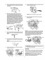
Preparing
the Pressure
Washer
for First Use
• Note: Included with your pressure washer is a video
tape on how to prepare your unit for operation. It is
recommended you view this tape before performing
the next steps.
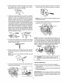
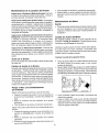
1. • Place handle on frame.
• Insert bolts into holes provided in handle.
• Line up handle and bolts with the holes provided
on frame.
• Insert bolts through
• Place washers and
nuts over bolts and
turning in clockwise
holes in frame.
over inserted bolts. Next place
tighten with adjustable wrench
direction.
Tools Required
for Assembly
Adjustable wrench
1/2" Socket wrench
Remove
Pressure
Washer
from
Carton
• Open box from the top. Locate and remove from
box, the parts box, which includes gun, handle,
wand, oil, nuts bolts and washers for handle
installation.
• Cut carton along dotted lines.
• Remove all carton inserts.
• Roll unit through opening in carton.
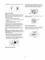
2. • Attach chemical basket to the pressure washer
frame opposite side of muffler. Holes are
provided on frame.
,
i
__
Chemical
Basket
Here
_
Hang
3. ° Remove wood plank from the frame of the unit.
An adjustable wrench is required. Discard bolt
and board.
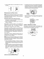
8. • Connect high pressure hose to the quick connect
outlet on pressure washer.
4
4. • Mount the rubber isolator to the frame. To
mount isolator place threaded end of bolt
through the washer. Next with washer on bolt
place threaded end of bolt through the rubber
isolator. Place threaded portion of isolator
through the same hole location the wood plank
was mounted to on the pressure washer. Next
place Iockwasher over threaded portion of nut
that has been placed through the mounting hole
in the pressure washer and use nut to tighten
isolator to the frame. Tighten nut with an
adjustable wrench. All isolator parts are
supplied in parts bag.
NUT _
WASHER
LOCK3NASHER
':_'
NOTE: Keep hose away from engine muffler.
9. • Place assembled
washer holder.
gun and wand on pressure
"_
_-ISOLATOR
L-
FRAME
_-"
WASHER
BOLT_
NOTE: Your unit's pump is shipped with a temporary
plug that must be replaced with a breather cap. This
plug is located over the pump's oil port. Unscrew
and remove this plug. Remove the breather cap from
the bag attached to the plug and install it in the
pump's oil port.
5. ° Connect wand with nozzle extension to gun. To
tighten, turn knob in clockwise direction. Hand
tighten.
=
•
BREATHER
6. ° Cut tie wrap off of high pressure hose. Unwind
high pressure hose to attach the threaded end to
thegun.
NOTE: Do not remove Teflon tape on threads.
CAUTION: Failure to replace the plug will result
in serious pump damage.
7. ° Connect chemical hose to the chemical injector
nipple on the pump.
Checklist
CHEMICAL
INJECTOR
Before going any further please review the following:
• Be sure you have completed assembly instruction.
• Double check all fittings to be sure they are tight.
P
IMPORTANT: Before any attempt to start your
pressure washer be sure to check engine oil (See
Operation underAdding Engine Oil.)
6
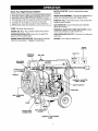
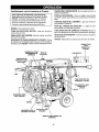
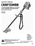
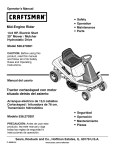
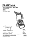
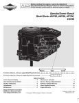
Know
Your High
Pressure
RECOIL STARTER- Used for starting the engine
manually.
Washer
Read this Owner's Manual and Safety Rules before
operation of your High Pressure Washer Compare
this iltuetrationwith our pressure washer to familiarize
yourself with the location of various controls and
adjustments, Save this manual for future reference,
PUMP- Develops high pressure.
SPRAY GUN ASSEMBLY- Controls the application of
water onto cleaning surface with trigger device.
PUMP OIL FILL- Port where pump oil is poured and
breather cap is located.
GAS TANK/CAP- Cap is removed and unleaded
gasoline is poured,
ENGINE OIL FILL- Place where engine oil is poured.
CHEMICAL INJECTION TUBE AND FILTER- Mixes
water and detergent in outlet water flow.
PRESSURE REGULATOR- Allows you to adjust the
pressure of the outlet stream.
HIGH PRESSURE OUTLET- Connection for high pressure hose.
ENGINE RUN/STOP SWITCH- Sets engine in starting
mode for recoil starter -- Stops running engine.
CHOKE- Lever used for starting unit.
ON/OFF
SWITCH
THROTTLE
CHEMICAL
BASKET
GAS CAP
I
%
GUN WAND
ASSEMBLY
HANDLE
CHEMICAL
INJECTOR
TUBE & FILTER
HIGH
PRESSURE
HOSE
PUMP
WATER INLET
CONNECTION
HIGH PRESSURE
OUTLET
CHEMICAL
ADJUSTMENT
KNOB
to operate equipment until you have read Owners
Manualfor Safety,
Operation,
and Maintenance
I A Warning:
Read Owner's
Manual.
Do not attempt
Instructions.
I
• Insert soap/chemical line into your container
net included).
• (soap/chemicals
Prepare the soap/chemical
as required by your job.
Note: Included with your unit is a video cassette that
demonstrates how to operate your pressure washer.
If you have a video cassette recorder you should
view the video before operation.
ing. Never put hands in front of spray nozzle to
_, Warning: Never adjust spray pattern when sprayadjust spray pattern because you cou d be n ured.
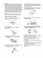
How To Use Your Pressure
Washer
On the end of your spray gun is a handle that you can
twist from side to side. With this handle you can adjust
the spray pattern to either high pressure or low
pressure.
• Twist the handle in a clockwise direction to achieve
low pressure. Twist handle counterclockwise for high
pressure.
NOTE: The first step involves applying an appropriate
soap/chemical solution to penetrate and loosen grime.
The soap/chemical applied at low pressure to avoid
splashing, over spray and waste. Leave the solution
on surface for 3 to 5 minutes to allow solution to work.
NOTE: The second step involves cleaning the surface
you have prepared with the pressure washer and then
rinsing it clean.
• Turn the adjustable nozzle counter clockwise to low
pressure mode. Soap/chemicals cannot be applied
with nozzle in high pressure position.
• Review the use of the adjustable nozzle.
Illl
• For most effective cleaning, keep spray nozzle
between 8 and 24 inches of cleaning surface.
• Connect garden hose to water inlet (see "To Start Your
Pressure Washer"), check that high pressure hose is
connected to spray gun and pump (see Assembly),
and start engine.
• Apply soap/chemicals to dry surface, starting from the
bottom and working up.
• Allow the soap/chemicals to soak in between 3-5
minutes before washing and rinsing.
IMPORTANT: If you get spray nozzle too close,
especially on high pressure, you may damage the
cleaning surface.
• For cleaning, start at lower portion of area to be
washed and work upward, using long, even overlapping strokes.
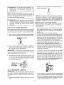
• The pressure control knob is located on the pump.
You can increase the pressure by turning the knob
clockwise or decrease the pressure by turning the
knob counterclockwise.
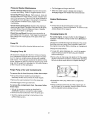
Your pressure washer is equipped with a chemical
injector adjustment knob. With the knob fully opened
you will get a 7 to 1 water to chemical ratio. With knob
fully closed you will get no chemical draw. Turn knob in
clockwise direction to achieve more chemical draw and
counterclockwise for less chemical draw.
PRESSU_
CONTROL
MOB
NOTE: The maximum pressure for-the unit is factory
adjusted. Do not attempt to adjust beyond this factory
setting.
Using Soaps/Chemicals
iMPORTANT: Use soaps and chemicals that are
designed specifically for use with pressure washers. To
apply soap/chemicals follow these steps:
• Prepare the soap/chemical as required by your job.
• insert soap/chemical line into your container (soap/
chemicals not included).
• After using the pressure washer, it is recommended
the pump, chemical injector and chemical line be
flushed with clear water. To do so, simply place
chemical injector hose in water and siphon for I to 2
minutes.
Stopping
Your
Pressure
Washer
A CAUTION: Do not run pump without the water
supply connected and turned on. Failure to do so
will result in pump damage.
• To turn pressure washer off place the on/off switch to
the off position.
• Simply shutting OFF engine will not release pressure
in the system. Squeeze the trigger on the spray gun
for about 3 seconds to relieve pressure. Spray
stream will decrease in length.
IMPORTANT: This unit is equipped with a thermal relief
valve. If unit is allowed to run for several minutes
without pressing the trigger on the spray gun, several
drops of water may be released through this valve to
cool the unit. This small amount of water will drip from
the bottom of the pump.
Engine
Oil
Your unit has been shipped without oil in the engine.
A bottle of SAE 30 weight oil is included in the
carton. Remove oil dip stick located on the side of
engine. The oil dip stick is clearly marked with a
lines that tells you when unit has enough oil. Do not
fill above this point. Pour slowly.
NOTE: When adding oil to the engine crankcase, use
a high quality detergent oil classified "For Service SF,
SG, SH rated SAE 30 weight. Use no special additives. Select the oil's viscosity grade according to
your expected operating temperatures.
SAE Viscosity Grades
|ll_'Ifl_]dl
TARTENG TEMPERATURERANGEANTICIPATED BEFORENEXT OIL GHANGE
BEFORE
STARTING
THE
ENGINE
To operate the engine you will need to do the following.
,& CAUTION: Always check engine oil level before
every start. Running engine low of oil or out of oil
could result in serious damage.
_, CAUTION: Always check pump oil level before
every start. Running pump low on oil could result
in pump damage.
Adding
Pump
Oil
Before running the high pressure washer, check the
pump oil level by viewing the sight glass on the side of
the pump. When properly filled, the oil will be at the
half way point marked by the two triangles. Your
pressure washer pump is shipped with oil. Add only if
oil level is lower than the half way point on the sight
glass. Do not overfill. Use 30 weight non-detergent oil
if necessary.
ACAUTION:
Do Not use engine oil that has been
shipped with your unit in your pump. Engine oil is
detergent and your pump uses a non-detergent
oil. Detergent oil can cause damage to your pump.
Air cooled engines run hotter than automotive engines.
The use of multi-viscosity oil such as (10W-30, etc.) in
ambient temperatures above 40°F (4°C) will result in
higher than normal oil consumption, if multi-viscosity
oil is used, check the oil level more frequently to
prevent any posssible engine damage due to lack of
lubrication.
Use of SAE30 oil below 40°F (4°C) will result in hard
starting and possible engine damage due to inadequate lubrication.
Gasoline
Your pressure washer engine is 4 cycle. Use unleaded
fuel only.
_, CAUTION: Do not overfill the fuel tank. Always
allow room for fuel expansion.
_,WARNING: Never fill fuel tank indoors. Never
fill fuel tank when engine is running or hot. Do
not smoke or have open flame when filling fuel
tank.
Use clean, fresh, regular unleaded gasoline with a
minimum of 85 octane. Do not mix oil with gasoline.
If unleaded fuel is not avalab[e, leaded fuel may be
used.
IMPORTANT: It is important to prevent gum deposits
from forming in essential fuel system parts such as the
carburetor, fuel filter hose or tank during storage. Also,
experience indicates that alcohol-blended fuels (called
gasohol or using ethanol or methanol) can attract moisture which leads to separation and formation of acids
during storage. Acidic gas can damage the fuel system
of an engine while in storage. To avoid engine problems,
the fuel system should be emptied before storage of 30
days or longer. Never use engine or carburetor cleaner
products in the fuel tank or permanent damage may
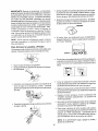
• Squeeze trigger on pressure washer wand to relieve air
pressure caused by turning on the water. Water will
spew out of the gun in a thin stream. This will make it
easier to start the engine.
• Engage the safety latch on the spray gun. This locks
the trigger in place and keeps you from accidentally
spraying a high pressure stream.
SAFETY
Occur.
I_ATCH
NOTE: Never start pressure washer without water
source turned on and connected to pressure washer.
To Start
Your Pressure
Washer
• On the engine there is a choke/run
to the choke position.
Make sure fuel shutoff valve is turned to the open
position. Turn couner-clockwise to open,
lever. Place lever
• On the engine there is a throttle control lever. Place
throttle to the rabbit position. Always start engine
with throttle in the rabbit position,
• Remove gas cap.
• Add unleaded gasoline, slowly, to fuel tank.
• Do not overfill.
• Grasp the starter grip and pull slowly until resistance
is felt, then pull firmly to start engine.
• Connect garden hose to the water inlet on the
pressure washer. Tigthen by turning water inlet
counterclockwise.
• Grasp the starter grip and pull slowly until resistance
is felt, then pull firmly to start engine.
• When engine starts, gradually move choke lever to
RUN position.
• If engine does not start after 5 pulls, place choke back
to run postion,
• For hot engine starts make sure choke lever is in the
run positon. Make sure fuel shut off valve is open and
throttle is in the rabbit position.
• Connect
high pressure hose to discharge on pump.
NOTE." If any leaks are present shut unit down and
tighten fittings,
• Connect the garden hose to the water spout
and turn water supply on.
10
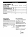
CUSTOMER
RESPONSIBILITIES
MAINTENANCE
PRESSURE
TABLE
Every 25
Before each use hours or yearly
TASK
Every 50
hours or yearly
Every 100
hours or yearly
WASHER
Check/clean inlet screen.
X
Check high pressure hose.
Check soap and chemical hose and 1liter
X
X
Check gun and wand for leaks.
X
Purge pump ofair and contaminants
X
Check pump oil
x
X
Change pump oil
ENGINE
Check oil level
x
Change engine oil
Product
General
Specifications
The warranty of the high pressure washer does not
cover items that have been subjected to operator
abuse or negligence. To receive full value from the
warranty, operator must maintain high pressure
washer as instructed in this manual.
Pressure Washer Specifications
Flow Rate
Pressure
Cleaning Units (psi x GPM)
3.0 GPM
3000 I
9000
Some adjustments will need to be made periodocally to maintain your high pressure washer.
Engine Specifications
RPM
Rated Horsepower
Spark Plug
Gasoline Capacity
Oil
Recommendations
All adjustments in the Maintenance section of this
manual should be make at least once each season.
3600
9.0
Once a year you should clean or replace the spark
plug and clean or replace the air filter and check
the gun and wand assembly for wear. A clean
spark plug and clean air filter assure proper
fuel-air mixture and help your engine run better
and last longer.
0.030" (0,76mm)
7 Gallon
SAE 30 weight
NOTE: Over time the o-rings in the gun assembly
become worn. Attach to your owners manual is a set
of repiacememt o-ring and split backup ring.
11
Pressure
Washer
Maintenance
• Pull the trigger on the gun and hold.
Check and Clean Inlet Screen: Examine inlet screen
on pump inlet fitting. Clean if clogged replace if torn.
• When the water supply is steady and constant,
disengage trigger and refasten the wand extension.
Check High Pressure Hose: High pressure hose can
develop leaks from wear, kinking, abuse. Inspect hose
each time before use. Check for cuts, leaks, abrasions
or bulging of cover, damage or movement of couplings.
If any of these conditions exist, replace hose
immediately.
Engine Maintenance
Oil
• Oil level should be checked prior to each use
or at least every 5 hours of operation. To check oil see
Adding Engine Oil on page 9.
Check Chemical/Soap
Hose: Examine the chemical/
soap hose and clean if clogged. Hose should fit tightly
on pump fitting. Check for leaks and tears. Replace
filter or hose if either is damaged.
Check Gun and Wand: Examine hose connection to
gun making sure it is secure. Test trigger by pressing it
and making sure it springs back into place when you
release it.
Changing
Engine
Oil
For a new engine, change oil after the first 5 hours of
operation. Thereafter, change oil after every 50 hours of
operation.
Change the oil while the engine is still warm. The oil will
flow freely and carry away more impurities. Make sure
the engine is level when filling, checking, or changing oil.
Pump Oil
Pump oil level should be checked before each use.
Change the oil as follows:
Changing
Pump
• To keep dirt, grass clippings, etc., out of the engine,
clean the area around the drain plug and dipstick
before removing it.
Oil
Oil should be changed after the first 10 hours of operation. Subsequent changes after each 50 hours of operation. To drain oil, simply remove oil plug with a adjustable wrench. The oil plug is located at the bottom of the
pump. Dispose of used oil. Properly remove pump oil fill
plug. Add 30 weight non-detergent oil. Fill until oil level is
at the mid point on the sight glass.
Purge
Pump
• Remove the oil drain plug and dipstick. Tilt the engine
slightly towards the oil drain to obtain better drainage.
Be sure to allow ample time for complete drainage.
of Air and Contaminants
To remove the air from the pump, follow these steps:
• Set up the pressure washer as described in
Assembly section and connect the water supply.
• Remove the wand extension from the spray gun,
• Reinstall the drain plug. Make sure it is tightened
securely.
• Pull the trigger on the gun and hold.
To remove the contaminants
these steps:
from
• Fill the crankcase with new oil of the proper type, to
the Full mark on the dipstick. Always check the level
with the dipstick before adding more oil.
the pump, follow
• Set up the pressure washer as described in
ASSEMBLY section, connect the water supply.
• Remove the wand extension from the spray gun.
• Start the engine according to instructions in the
OPERATION section.
12
• Reinstall
theoilfill capor plugandtightensecurely.
Service
Do not clean engine with a forceful spray of water
because water could contaminate fuel system. With
a brush or cloth clean finger guard after every use to
prevent engine damage caused by overheating.
Air Cleaner
NOTE: Do net use petroleum solvents, e.g., kerosene,
which will cause the cartridge to deteriorate. Do not use
pressurized air to clean cartridge. Pressurized air can
damage the cartridge.
Before running engine, clean muffler area to remove all
combustible debris.
To service air cleaner follow these steps:
CLEAN
1. Unscrew cover screws. Remove cover and air cleaner
assembly.
2. Remove cartifidge from cover, then retainer
(if equipped) and pre-cleaner.
To service pre-cleaner, wash in liquid detergent and
water. Squeeze dry in a clean cloth. Saturate in engine
oil. Squeeze in clean, absorbent cloth to remove all
excess oil. Replace if very dirty or damaged.
Clean and Replace Spark Plug
To service cartridge, clean by tapping gently on a flat
surface. Do not oil cartridge. Replace if dirty or damaged,
Change the spark plug every 100 hours of operation or
once each year, whichever comes first. This will help
your engine to start easier and run better,
NOTE: Do not use petroleum solvents, e.g., kerosene,
which will cause the cartridge to deteriorate. Do not use
pressurized airto clean cartridge. Pressurized air can
damage the cartiridge.
,030" (0.76 MM)
WIRE GAGE
3. Reassemble pre-cleaner or retainer (if equipped.)
Place in cover with pre-cleaner mesh side toward
cartridge. Place cartridge in retainer in cover.
4. Push cover and air cleaner assembly squarely onto
base (tabs must be in slots, if equipped) and hold
firmly. Tighten cover screws securely.
RESISTOR
Keep engine and parts clean!
13
Carburetor
Nozzle
The carburetor of your high pressure washer is pre-set
at the factory. The carburetor should net be tampered
with. If your pressure washer is used at an altitude in
excess of 5000 feet consult with your nearest Sears
Service Center regarding high altitude set changes.
Dual Lance:
Maintenance
1. Shut off the pressure washer and turn off the water
supply.
_, CAUTION: Engine speed was properly adjusted
at the factory and should require no additional
adjustment. Do not attempt to change engine
speed. If you believe the engine is running too fast
or too slow, take your pressure washer to a Sears
Authorized Service Center for repair and adjustment.
2.
Disconnect spark plug wire.
3.
Pull trigger on gun handle to relieve any water
pressure.
4.
Disconnect the wand/lance from the gun.
5.
Remove the high-pressure nozzle from the lance.
Remove any obstructions with the nozzle cleaning
tool provided and backflush with clean water.
,
_&High engine speeds are dangerous and increase
the risk of personal injury or damage to equipment.
Direct water supply into nozzle end to backflush
loosened particles for 30 seconds.
7. Reassemble the nozzle to the lance using teflon tape
to prevent leaks. Tighten securely.
_, Low engine speeds impose a heavy load on the
engine and when sufficient engine power is not
available could shorten engine life.
8. Reconnect wand/lance to gun and turn on water
supply.
9. Start pressure washer and place wand/lance
high pressure setting to test.
• Add one teaspoon
This pressure washer should be stored in such a way to
protect it from freezing. Do not store this unit outdoors
or in an area where temperatures will fall below 32 ° E
This can cause extensive damage to this unit.
Pump
Pressure
Washer
for Storage
Preparation
• Be sure engine switch is in "OFF" position and spark
plug wire has been removed from spark plug.
NOTE: If you do not plan to use your unit for 30 days or
more, unit should be prepared for storage.
Engine
of oil through the spark plug hole.
• Place rag over spark plug hole and pull the recoil a
few times to lubricate the combustion chamber.
• Replace the spark plug, but do not connect the spark
plug wire.
If unit has to be stored under freezing conditions a nontoxic R.V. anti-freeze can be used to protect from
freezing.
Preparing
into
• Pull the trigger on the spay gun to release the
pressure in the high pressure hose. Detach high
pressure hose and garden hose from the unit.
• Pull the recoil on the engine 4 to 6 times to discharge
remaining water in pump.
Preparation
• First add a fuel stabilizer to the fuel tank.
• Tip the unit on the end with the water inlet fitting
pointing upward.
• Run pressure washer for full 5 minutes to allow fuel
stabilizer to enter the fuel system.
• Pour approximately 1/4 cup of non-toxic R.V. antifreeze down the fitting where the water hose attaches
to the pump.
NOTE: While doing this procedure make sure water
supply is turned on and flowing to the unit. NEVER run
unit without water supply running through pump.
• Set unit upright and pull starter handle on engine 4 to
6 times to circulate anti-freeze in pump until antifreeze is discharged from the pump.
• Next shut off engine and disconnect the water supply.
• Disconnect the spark plug wire and remove the spark
plug.
14
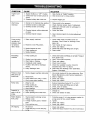
SYMPTOM
CAUSE
SOLUTION
Engine won't
start
1. Engine throttle is in "OFF" Position.
2. Choke lever has not been placed to
choke.
1. Slide throttle to "Rabbit" position.
2. Slide choke lever to choke position.
3. Pressure buildup after initial use.
Won't Draw
Chemical
3.
1. Nozzle not in chemical draw position
2. Chemical screen is obstructed.
3. Chemical screen not working.
4. Chemical injector orifice obstructed
or stuck.
5. Chemical injector closed.
Pump running
normally but
pressure does
not achieve
rated values
1. Water supply restricted.
2,
Nozzle is in low PSI position.
3.
4.
Nozzle incorrect or worn.
2.
3.
4.
5.
1. Pump sucking air.
injector
by turning
in
adjustment
kinks,
Twist handle for high pressure,
Check and replace.
Check that hoses and fittings are air-tight.
Clean nozzle.
1. Check that hoses and fittings are air tight. Purge air
from garden hose.
2. Clean. Check filter frequently.
3. Check and replace,
4. Check hose for kinks.
5. Check flow available to pump. Check for
excessive heat, 145o F or above.
6. Clean inlet and discharge valve assemblies.
Replace if damaged.
valves.
6. Leaky discharge hose.
1. Nozzle clogged, partially obstructed.
2. Nozzle worn.
3. Pump Valves worn, dirty or stuck.
4. Worn pump piston packing.
Presence of
water in oil (oil
milky).
screen is submerged
blockage. Check hoses for blockage,
leaks, etc.
4. Inadequate water supply.
5. Fouled or dirty inlet or discharge
Pump noisy
3. Make sure chemical
chemical/water.
4. Check and clean.
1. Check water supply and filter screen for.
2. Garden hose inlet strainer clogged.
3. Worn Seals or Packing.
Pressure drops
after period of
normal use
1. Place nozzle to low pressure.
2. Check chemical screen; clean if obstructed.
5. Open chemical
knob.
Pump sucking air.
5. Nozzle blocked.
Fluctuating
Pressure
Depress trigger gun.
2. Pump sucking air.
3. Valves dirty or worn.
4. Worn bearings.
1. Reduce temperature below 63° C or 1450 F.
2. Check that hoses and fittings are air tight.
3. Check, clean or replace.
4. Check and replace if necessary,
High humidity.
2. Piston packing
1. Change Oil.
2. Check and replace oil seals.
1,
Water too hot.
1. Use nozzle cleaning kit to clear obstruction. (See
Nozzle Maintenance under Service Adjustment.)
2. Clean or replace,
3. Check and replace.
4. Check and replace.
1.
and oil seal worn.
Water dripping
from pump
1.
Thermal relief functioning normal.
2, Fittings Loose.
3. O-rings of piston guide or retainer
worn.
4.
Piston packing worn.
1. Protecting pump, if not using pressure washer for
a long period of time, shutoff engine.
2. Tighten.
3. Check and replace.
4. Check and replace.
Oil Dripping
1. Oil seal worn
2. Loose drain plug or worn drain plug
o-ring.
1_ Check and replace
2. Tighten drain plug or replace O-ring. Do not over torque.
15
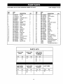
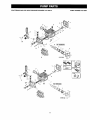
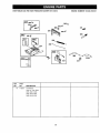
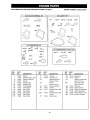
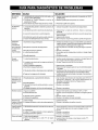
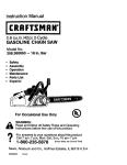
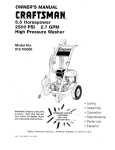
CRAFTSMAN
3000 PSI HIGH PRESSURE WASHER 919.763010
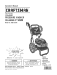
REF.
NO.
PART
NO.
DESCRIPTION
QTY.
1
AR-960160
O-Ring
6
2
I3
4
5
6
7
AR-1260162
AR-1269050
AR-880830
AR-620301
AR-1780130
AF_L1260130
Plug
CompletevaIve
O-Ring
Plug
Support ring
Gasket
6
6
6
1
3
3
8
9
10
11
12
13
14
15
16
17
18
19
20
21
22
AR-1780090
AR-1780010
AR-1266740
AR-1260790
AR-1780550
AR-1780490
AR-880130
AR-1780050
AR-1780510
AR-1200430
AR-1789010
AR-1780040
AR-1780060
AR-480480
AR-1260091
Piston guide
Pump body
Cap
Circlip
Snap ring
Bearing
Oil cap
Piston pin
O-Ring
Screw
Complete cover
Con rod
Guiding piston
O-Ring
Spacer disc
3
1
1
1
1
1
1
3
1
6
1
3
3
3
3
PARTS
DESCRIPTION
Piston
Piston washer
Nut
O-Ring
Plug
Seal
Rear piston guide
O-Ring
Gasket
Head
Washer
Screw
Bearing
Snapring
Seal
Screw
Hollow shaft 0 1
Gas engine flange
13ushing
Grub screw
68
69
70
71
AR-1789200
16802
16749
16506
Pump head pre-ass 1
Chemical Injector
1
Unloader
Thermal Relief Valve 1
KITS
C=KIT 16748
Oil Seals for
D Version
Pos.
3
4
Pos.
23
Pos.
10
16
3O
42
D=KIT 16745
Water Seals
F=KIT 16749
Bearings
Pos.
Qty.
Pos,
7
32
3
3
13
40
33
3
Qty,
1
1
3
1
L=KIT 16750
Unloader
Qty.
1
1
16
QTY.
3
3
3
2
2
3
3
3
3
1
8
8
1
1
1
4
1
1
1
1
PART
NO.
AR-1780070
AR-1260100
AR-1260110
AR-740290
AR-880530
AR-1260460
AR-1780100
AR-770260
AR-1260440
AR-1780380
AR-1381550
AR-680570
AR-1321160
AR-1321080
AR-480671
AR-180030
AR-1780340
AR-1380550
AR-1780430
AR-820440
B=KIT 16746
Pistons
Qty.
3
PK16803
REF.
NO.
23
24
25
27
28
30
31
32
33
36
37
38
40
41
42
44
60
61
62
67
A=KIT 16739
Valves
Qty.
6
6
PUMP NUMBER
K=KIT 16802
Pos. Qty.
Pos.
70
69
1
Qty.
1
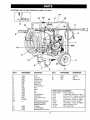
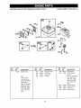
CRAFTSMAN
3000 PSI HIGH PRESSURE WASHER 919.763010
PUMP NUMBER
16
!4
10
15
19
_22
25
\
69
68
C
_L
A
K
F
0
D
\
C
17
24
PK16803
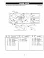
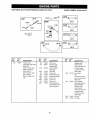
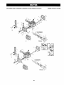
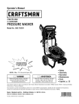
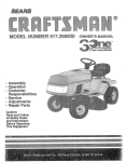
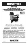
CRAFTSMAN
3000 PSI HIGH PRESSURE WASHER
919.763010
19
13
22
18
11
12
I
17
10
I
\
9
1
900
15
8
14
23
7
6
5
KEY#
PARTNUMBER
DESCRIPTION
KEY#
PARTNUMBER
DESCRIPTION
!
16575
Frame
DualLance
ChemicalHose
Tire Pnuematic
16597
16611
F112
FuelCap
Axle
Washer,Flat
4
16824
H1O0
16588
22
23
26
7
F464
16371
F064
Nut
Pal5/8"
Rubber
Foot
Screw,Hex HDC
10
11
12
!3
!4
15
900
15911
16586
16496
t 6652
16610
16763
F039
PK16803
.....
17
18
19
16830
16593
16728
Hose
Handle
Gun
Tank
Decal Craftsman
Heat Shield
Hose QuickConnect
Pump
Engine (Refer to Engine
Breakdown Briggs
#185432-0035-A1)
O-RingKit
ChemicalBasket
Decal OperationInstruction
18
PARTS
NOT
MGP-763010
F078
Fl19
F066
F107
16106
F074
NCT001
16776
ILLUSTRATED
Owners Manual
Lockwasher, Engine to Frame
Nut Hex 5/16"- Engine to Frame
Screw 5/16"- Engine to Frame
Lockwasher- Pump to Engine
Srew, Hex- Pump to Engine
Flat Washer - Pump to Engine
Nozzle Cleaning Tool
Easy Start Valve
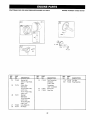
CRAFTSMAN
3000 PSI HIGH PRESSURE WASHER 919.763010
I16A
ENGINE
NUMBER
185432-0559-E1
505
3
"_" REQUIRES SPECIAL TOOLS
TO REPLACE. SEE REPAIR
INSTRUCTION
MANUAL-
11019 LABEL
REF.
PART
REF.
PART
NO.
NO.
DESCRIPTION
NO.
NO.
DESCRIPTION
1
715095
Cylinder
116A
227
710091
710238
Seal-O-Ring
Lever-Governor
3
710000
710023
Seal-Oil
Screw-Hex.
Plug-Oil Drain
Bearing-Ball
710058
230318
710004
Washer-Spacer
Connector-Hose
Washer-Seal
17
715000
710003
230
244
277
306
356
710242
710308
116
710055
Seal=O-Ring
10
15
Assembly
KIT I [1058 OWNER'S
MANUAL
REF.
PART
NO.
NO.
DESCRIPTION
601
614
710407
710056
Clamp-Hose
Pin-Retainer
616
710050
Crank-Governor
718
710005
Pin-Locating
948
710417
Harness-Wiring
Shield-Cylinder
Wire-Oi+ Sensor
1019
715031
Label Kit
1052
1053
715353
710408
Sensor-Oil
Module
373
710059
Nut-Lock
493
710085
Bracket-Mounting
Used on Type No(s).
505
710090
0099.
Nut-Lock
526
710089
Screw-Hex.
19
I
Used on Type No(s).
0099.
1058
272983
Owner's
Manual
CRAFTSMAN
3000 PSI HIGH PRESSURE
WASHER 919.763010
ENGINE
NUMBER
185432-0559-E1
lO_
22A
220
-7
718A
12
REF.
PART
NO.
NO.
DESCRIPTION
10
12
710023
710216
Screw-Hex.
Gasket-Crankcase
17
710003
Bearing-Bal!
18
715189
Cover-Crankcase
17
REF.
PART
NO.
NO.
DESCRIPTION
20
710215
Seal-Oil
22
710032
Screw-Hex.
REF.
PART
NO.
NO,
DESCRIPTION
225
710028
Shaft-Governor
22A
710306
Screw-Hex,
524
710394
Seal-Oil
116B
710218
Seal-O-Ring
525
710391
Tube-OilFill
116C
219
805386
715006
Seal-O-Ring
Gear-Governor
527
710100
Clamp-Tube
220
710035
Washer-Spacer
718A
725
710034
710259
Pin-Locating
Shield-Heat
221
710027
Cup-Govemor
20
Gear
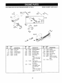
CRAFTSMAN
3000 PSI HIGH PRESSURE WASHER 919.763010
185432-0559-E1
.868
I
45
10
1026
383
REF.
PART
NO.
NO.
DESCRIPTION
REF.
PART
NO.
NO.
DESCRIPTION
710233
Stud-Carburetor
53A
710099
Mounting
Stud
337
491055
373A
710007
53
REF.
PART
NO.
NO.
DESCRIPTION
383
551
19374
715091
Wrench-Spark
Cover-Valve
635
830
710098
710016
Boot-Spark Plug
Stud-Rocker
Arm
5
715089
Head-Cylinder
7
710205
10
710023
Gasket-Cylinder
Screw-Hex.
13
710204
33
715085
Screw-Cylinder
Valve-Exhaust
868
710019
Seal-Valve
34
715087
Valve-Intake
1022
710206
Gasket-Rocker
35
710209
1026
710210
Rod-Push
Head
Head
Plug-Spark
Nut-Lock
Plug
Cover
40
710012
Spring-Valve
Retainer-Valve
1029
710014
Arm-Rocker
40A
715130
Retainer-Valve
1034
710203
Guide-Push
45
710008
Tappet-Valve
1050
710015
Adjuster-Rocker
21
Rod
Arm
CRAFTSMAN
3000 PSI HIGH PRESSURE WASHER 919.763010
ENGINE
NUMBER
185432-0559-E1
* 17A
756
17A
32
REF.
PART
NO.
NO.
17A
25
710482
715115
DESCRIPTION
Bearing-Ball
REF.
PART
NO.
NO.
29
715106
DESCRIPTION
Rod-Connecting
Used on Type No(s).
0099.
(Standard)
715017 Rod-
Piston Assy.
Connecting
(Standard)
715116 Piston Assy.
32
710221
(.020" Undersize)
Screw-Hex.
(,010" O,S.)
46
715249
Gear-Cam
715117 Piston Assy.
(,020" O,S.)
26
715111
Ring Set
(Standard)
715112 Ring Set
(.010" O.S.)
715113 Ring Set
27
710220
(.O2O" O.S.)
Lock-Piston Pin
28
715114
Pin-Piston
22
REF.
PART
NO.
NO.
DESCRIPTION
719
710219
Pin-Lifter
1051
710039
Ring-Retaining
CRAFTSMAN
3000 PSI HIGH PRESSURE WASHER 919.763010
ENGINE
NUMBER
185432-0559-E1
843Q
-_562
663_*_
211
281
663 _
2221188_
232
202
356A
347
REF.
PART
NO,
NO.
DESCRIPTION
715235
Crankshaft
16
Used on Type No(s).
0035,0037,0046,
0059,0076,
0084,
0099, 0136, 0235
23
CRAFTSMAN
3000 PSI HIGH PRESSURE
130
95A_
WASHER 919.763010
ENGINE
NUMBER
185432-0035-A1
I
108 _
987 _)
615 ._
634A
255
255A ÷
634
51A
_57
104
147_
A
1091
138
REF.
PART
NO.
NO.
DESCRIPTION
REF.
PART
NO.
NO.
DESCRIPTION
51
51A
710235
710237
Gasket-Intake
Gasket-Intake
125
715121
Carburetor
Adjustment
130
131
710323
715154
Valve-Throttle
Throttle Shaft Kit
94
715076
Valve-Idle
94A
715293
Valve-Idle
Adjustment
133
715158
Float-Carburetor
Used on Type No(s).
0235.
137
Gasket-Float
138
(Sold in Kit Only)
Washer
95
710191
Screw-Choke/Throttle
95A
710186
Screw-Round
98
494690
Screw-idle
104
105
710310
715155
Pin-Float Hinge
Valve-Needle
108
710322
Valve-Choke
117
710316
Jet-Main
REF.
PART
NO.
NO.
DESCRIPTION
141
715157
Choke-Shaft
142
710317
Nozzle-Carburetor
147
710321
Jet-Pilot
710511 Jet-Pilot
Bowl
254
715049
(High Altitude)
Drain-Carburetor
255
710177
Bushing-Choke
255A
710312
Bushing-Choke
710175
(Lower)
Retainer
(Sold in Kit Only)
Head
615
634
Washer-Throttle
715120
634A
Spacer-Carburetor
24
Shaft
Shaft
(Sold in Kit Only)
Seal-Choke Shaft
710512 Jet-Main
122
Bowl
Shaft
(Upper)
Speed
(High Altitude)
Kit
955
975
710314
715159
(Sold in Kit Only)
Plug-Carburetor
Bowl-Float
987
710185
SeaI-ThrottleShaft
1091
710485
Cap-Limiter
CRAFTSMAN
3000 PSI HIGH PRESSURE
WASHER 919.763010
ENGINE
NUMBER
185432-0035-A1
957
642
534_
346A_
535
161 "_
971
346
176
819 ;_
863A _"_
REF.
PART
NO.
NO.
DESCRIPTION
710235
Gasketqntake
51
REF.
PART
NO.
NO.
DESCRIPTION
710258
710240
Spring-Governor
Link-Choke
209
216
Note
819
REF.
PART
NO.
NO.
DESCRIPTION
485
280715
Knob-Control
620
715046
715025
Bracket-
232
710241
Spring-Link
Control
302
710081
Nut-Hex,
Used on Type No_),
715024 Screw-
0035, 0037,0043,
Governor
(Idle & High Speed
0046,0047,0059,
0072,0076, 0084,
Adjustments)
0103, 0106, 0112,
Speed
0235.
Used in Type No_).
620A
710492
Bracket-Control
0046,0047,0059,
620B
710493
Bracket-Control
0072,0076,0084,
663
710057
Screw-Hex.
1043
494232
Magnet-Electro
0035,0037,
0043,
0103, 0106, 0112,
0235.
25
CRAFTSMAN
3000 PSi HIGH PRESSURE
WASHER 919.763010
ENGINE
. _
o
48
j>.,
/1
REF.
PART
NO.
NO,
185432-0559-E1
20'
S
663
, SP_ED
=
IDLE
NUMBER
J
REF,
PART
REF.
PART
DESCRIPTION
NO.
NO,
DESCRIPTION
NO.
NO.
DESCRIPTION
116D
161
280831
710226
Seal-O-Ring
Base-Air Cleaner
663A
710234
Screw-Hex.
967
710226
Filter-Air
710229
710068
Shield-Fuel
Nut-Hex.
968
710227
Cover-Air
991
710268
Filter_Air
10
710023
Screw-Hex.
11
710115
Tube-Breather
51
710235
Gasket-Intake
51B
272070
Gasket-Intake
235
354
53
710233
Stud-Carburetor
467
710113
Nat-Air
Mounting
643
710228
Retainer-Air
646
710232
Brace
26
Spray
Cleaner
Filter
Cleaner
(Pre-Cleaner)
CRAFTSMAN
3000 PSI HIGH PRESSURE WASHER 919.763010
ENGINE
988\
REF.
PART
NO.
NO.
DESCRIPTION
38
710248
Screw-Hex.
53A
710099
180
181
182
NUMBER
185432-0559-E1
i -"
REF.
PART
NO.
NO.
DESCRIPTION
REF.
PART
NO.
210
710065
Strainer-Fuel
529
NO.
DESCRIPTION
710246
Stud
300
715127
Muffler-Exhaust
Grommet
663
710057
302
710081
715129
(Muffler Mounting)
Tank*Fuel
Screw-Hex.
Nut-Hex.
668
710243
346
Gauge-Fuel
710307
Screw-Phillips
710068
Nut-Hex.
670
673
710247
93705
710490
710244
Cap-Fuel Tank
Bracket-Fuel Tank
354
Spacer
Screw-Hex.
676
715230
Deflector_Muffler
737
710074
Screw-Shoulder
832
710334
Guard-Muffler
863
715495
Bracket-Muffler
883
710250
Gasket-Exhaust
994
715491
Arrester-Spark
1057
710331
ScreemOutlet
27
CRAFTSMAN
3000 PSI HIGH PRESSURE WASHER 919,763010
ENGINE
NUMBER
185432-0559-E1
737
!
1057
©
883
3o2_
53A
38
182
fJ _/
1B2B _
-
3_4
670 @
s29 _
REF.
PART
REF.
PART
NO.
NO.
DESCRIPTION
NO,
NO,
DESCRIPTION
167B
296004
REF.
PART
NO.
NO.
DESCRIPTION
38
710248
Screw-Hex.
Line-Fuel
243
710071
Screen-Filter
116E
710072
Seal-O-Ring
(0,250 in, ID)
246
710070
Bowl-Filter
116F
710069
(Used After Code Date
601A
710075
Clamp_Hose
179
715172
Seal-O-Ring
Line-Fue!
95073100).
601B
710067
Clamp-Hose
(Filter/Shut-Off-To_
601C
663A
95053
710234
Clamp-Hose
Screw-Hex,
663B
710160
Screw-Hex.
670A
710159
Spacer-Fuel
(Used Before
187
715125
Code
Date 95080100).
Fuel Pump)
Used on Type No(s).
(Carb-To-ln
0837, 0041, 0842,
(Cut to Required
0071, 0078, 0075,
Length)
Hose-Vacuum
0877, 0082.
LineWuel
187C
715292
(4MM ID Special
(Smm ID)
Flexible Hose)
(Fuel Tank-To Filter/
(Fuel Pump_To_Carb.)
Shut-Off)
(Cut to Required
187A
715126
Line Filter)
240
298090
(Cut to Required Length
Filter=Fuel
Length)
Line-Fuel
Note
(4mm ID)
Used on Type No(s).
0099.
493629 Filter-Fuel
(Filter/Shut-Off-ToCarburetor)
240A
715027
Filter_Fuel
(Cut to Required
Note
Length)
715224 Filter-Fuel
Used on Type No(s).
0103.
28
Tank
CRAFTSMAN
3000 PSI HIGH PRESSURE WASHER 919.763010
ENGINE
NUMBER
185432-0559-E1
601 A
/
601A
116F
243 91P
116E
246_
601C
601 B
601 C
REF.
PART
NO.
NO.
DESCRIPTION
715321
Panel-Control
(Used A_er Code Date
281
REF.
PART
NO.
NO.
DESCRIPTION
305
710095
Screw-Hex.
347
493521
Switch-Rocker
347A
495098
(Without Light)
Switch-Rocker
356E
715202
0047*09, 0051.0070,
447
710253
Wire-Stop
Screw-Hex.
0071, 0072-01,
493
710363
BrackehMounting
493A
71O717
663
710057
Bracket-Mounting
Screw-Hex.
663A
710234
Screw-Hex.
737
710074
Screw-Hex.
890A
710094
Bracket-Support
(Used Before
(Used Before Code
Date 96010206),
Date 96010200).
Replaced with
Panel-Control:
715321 for Non-Elec-
96010160).
Used on Type NOR).
0035-01,
0035-02,
0046, 0047-01,
0076-02,
0107.
0090, 0103,
REF.
PART
NO.
NO.
DESCRIPTION
Replaced with
PaneI-Controh
715321 for Non-Electric Start Engine
715322 for Electric
(With Light)
Start Engine
892
715199
Key Switch
Note
710716 Key Switch
Used on Type No(s).
0059, 0084.
925
710252
Cover*Linkage
Code
tric Start Engine
715322 for Electric
29
990
715203
1054
710349
Start Engine
Key Set
Tie-Cable
CRAFTSMAN
REF.
NO.
3000 PSI HIGH PRESSURE
PART
NO.
DESCRIPTION
WASHER 919.763010
REF,
NO.
333
ENGINE
REF.
PART
NO.
DESCRIPTION
NO.
NO.
DESCRIPTION
715118
710047
Armature-Magneto
Screw_Hex.
475
715200
Rectifier
710087
Wire-Stop
(Black)
521
528
710045
710089
Shielding-Cable
Screw-Hex.
(Red)
663A
710234
Screw-Hex.
729
813
710046
710083
Clip-Lead
Clamp
1036
499351
Label Kit-Emission
10
710223
Screw-Hex,
710224
Flywheel
73
224757
Screen-Rotating
304
332
710364
710048
Housing-Blower
Nut-Hex.
356B
710120
Wire-Stop
356C
332A
710345
Nut-Hex.
356D
710121
710324
Wire-Stop (White)
Wire=Ground
Note
Used on Type No(s).
0099.
710366
Cup=Flywheel
(Used After Code Date
93123100).
455A
710257
Cup-Flywheel
(Used Before Code
Date 94010100),
Note
710230 Cup-Flywheel
Used on Type No(s).
0072.
30
Wire
Used on Type No(s).
0235.
710097 Wire-Ground
455
185432-0559-E1
PART
23
334
356A
NUMBER
1053
710305
Module
CRAFTSMAN
3000 PSI HIGH PRESSURE WASHER 919.763010
ENGINE
NUMBER
185432-0559-E1
1084_
332A %_
304
10_
73
1053
t1036
EMISSION
REF.
PART
NO.
NO.
DESCRIPTION
898186
Housing-Rewind
Starter
55
LABEL
KIT f
REF.
PART
NO.
NO.
DESCRIPTION
59
805957
Insert-Grip
60
456
808167
805954
Grip-Starter Rope
Piate-Pawl Friction
Note
459
808166
PawFRatchet
Rewind
Rope-Starter
461
805955
Screw=Shoulder
(Used Before
(Cut to Required
515
805953
Spring-Pawl
Date 94010100).
56
805949
Puliey_Starter
57
805951
Spring-Rewind
58
66574
Starter
Length)
REF.
PART
NO.
NO.
DESCRIPTION
808087
Starter-Rewind
608
715204 Starter-
615
737
31
805952
710074
Ring-Rewind
Screw-Hex.
Code
Starter
CRAFTSMAN
3000 PSI HIGH PRESSURE WASHER 919.763010
ENGINE
NUMBER
185432-0559-E1
515A
\.--.
\_
-
_ ........
456A
737
REF.
PART
NO.
NO.
DESCRIPTION
492193
Housing-Rewind
Sta_er
55A
REF.
PART
REF.
PART
NO,
NO.
DESCRIPTION
NO.
NO,
DESCRIPTION
59A
490653
Inset-Grip
60A
69
490652
94464
Grip-Sta_er
Washer
515A
608B
262564
715204
Spring-Fdction
StaAer-Rewind
737
710074
Screw-Hex.
69A
94462
Rope-Sta_er
456A
224228
Plate-PawlFriction
(Cutto
459A
492431
Pawl Ratchet
461A
94463
56A
494956
Pulley*Sta_er
57A
492194
Spring-Rewind
58A
66894
Length).
Requi_d
Sta_er
Rope
Washer
Screw-Shoulder
32
CRAFTSMAN
3000 PSI HIGH PRESSURE WASHER 919.763010
1033 VALVE OVERHAUL
ENGINE
KIT
NUMBER
185432-0559-E1
358 GASKET SET
116 (¢_
5! _J/
883
110A_
,,=, _,_i 116E _,_
20
3
51
116F#
-
277
883
/
{0
7
_
121 CARBURETOR
138_
987 _
634
147_
142 _
KIT
615_
977 CARBURETOR
634A
lO4
255A
138 L_
634
PART
NO.
DESCRIPTION
3
710000
Seal-Oil
7
12
710205
710216
Gasket-Cylinder
Head
Gasket-Crankcase
20
710215
Seal-Oil
REF.
PART
NO.
NO.
DESCRIPTION
1!7
710316
Jet-Main
121
715156
Carburetor
Kit
Bow]
REF.
PART
NO.
NO.
DESCRIPTION
358
715124
Gasket Set
615
710175
138
(Sold in Kit Only)
Washer
634A
868
710019
(Sold in KitOnly)
Seal-Valve
883
710250
Gasket-Exhaust
977
715160
Gasket
987
710185
SeaI-Thre_le
1022
710206
Gasket-Rocker
1033
715123
K_-Valve
Gasket-Intake
710237
Gasket-Intake
104
105
710310
715155
Pin-Float Hinge
Valve-Needle
142
710317
(Sold in Kit Only)
Nozzle-Carburetor
147
710321
Jet-Pilot
116
116A
710055
710091
Seal-O-Ring
Seal-O-Ring
255
710177
Bushing-Choke
(Upper)
Shaft
116B
710218
Seal-O-Ring
255A
Bushing-Choke
(Lower)
Washer-Seal
Shaft
277
710312
710004
33
634
Retainer
Gasket-Float
710235
Seal-O-Ring
Seal-O-Ring
_
137
51
710072
710069
634A
,1A
<4)
51A
116E
116F
_
SET
9
137 _%
NO.
GASKET
2ss6
117
REF.
1022
Washer-Thro_le
Shaft
(Sold in Kit Only)
Seal-Choke Shaft
Set-Carburetor
Shaft
Cover
Overhaul
Bdggs & Stratton Corporation (B&S), the California Air Resources Board (CARB)
and the United States Environmental Protection Agency (U.S. EPA)
Emission Control System Warranty Statement (Owner's Defect Warranty Rights and Obligations)
In the interest of the envirenment, B&S engines that meet stdctemisTO CERTIFIED ENGINES PURCHASED IN CALIFORNIA IN 1995
sion requirements arelabeled,"Thisengineconformsto
1995-1998
AND THEREAFTER, WHICH ARE USED iN CALIFORNIA, AND
California emission regulations for ULGE engines and U.S. EPA
TO CERTIFIED MODEL YEAR 1997 AND LATER ENGINES
Phase I regulations for small non-road engines."
WHICH ARE PURCHASED AND USED ELSEWHERE IN THE
EMISSION CONTROL WARRANTY COVERAGE iS APPLICABLE
UNITED STATES.
California and United States Emission Control Defects Warranty Statement
there has been no abuse, neglect or improper maintenance of your
CARB, U.S. EPA and B&S are pleased to explain the Emission
ULGE engine.
Control System Warranty on your 1996 and later utilityor lawn and
Your emission control system includes parts such as the carburetor,
garden equipment (ULGE) engine. In California, new ULGE engines
air cleaner, ignition system, muffler and catalytic converter. Also
produced on or after August 1, 1995 must be designed, built and
included may be connectors and other emission related assemblies.
equipped to meet the State's stringent anti-smog standards., Elsewhere in the United States, new non-read, spark-ignition engines
Where a warrantable condition exists, B&S will repair your ULGE
certified for model year 1997 and later, must meet similar standards
engine at no cost to you including diagnosis, parts and labor.
set forth by the U.S. EPA. B&S must warrant the emission control
system on your engine for the periods of time listed below, provided
Briggs & Stratton Emission Control Defects Warranty Coverage
ULGE engines are warranted relative to emission control parts
below,tfanyeoveredpartonyourengineisdefective,
thepartwillbe
defects for a period of two years, subject to provisions set forth
repairedor replaced by B&S.
Owner's Warranty Responsibilities
You are responsible for presenting your ULGE engine to an AuthoAs the ULGE engine owner, you are responsible for the performance
rized B&S Service Dealer as soon as a problem exists. The undisof the required maintenance listed in your Operator/Owner Manual.
puted warranty repairs should be completed in a reasonable amount
B&S recommends that you retain all your receipts covering mainteof time, not to exceed 30 days.
nance on your ULGE engine, but B&S cannot deny warranty solely
for the tack of receipts or for your failure to ensure the performance of
If you have any questions regarding your warranty rights and
all scheduled maintenance.
responsibilities, you should contact a B&S Service Representative
at 1-414-259-5262.
As the ULGE engine owner, you should however be aware that B&S
The emission warranty is a defects warranty. Defects are judged on
may deny you warranty coverage if your ULGE engine or a part has
normal engine performance.The warranty is not related to an in-uso
failed due to abuse, neglect, improper maintenance or unapproved
emission test.
modifications.
Brlggs & Stratton Emission Control Defects Warranty Provisions
The following are specific provisionsrelative to your Emission Control Defects Warranty Coverage. It is in addition to the B&S engine warranty
for non-regulated engines found in the Operator/Owner Manual.
3. No Charge
1. Warranted Parts
Repair or replacement of any Warranted Part will be performed
Coverage under this warranty extends only to the parts listed
at no charge to the owner, including diagnostic labor which leads
below (the emission control systems parts) to the extent these
to the determination that a Warranted Part is defective, if the
parts were I:. 3sent on the engine purchased.
diagnostic work is performed at an Authorized B&S Service
a. Fuel Metering System
Dealer. For emissions warranty service contact your nearest
Authorized B&S Service Dealer as listed in the "Yellow Pages"
•
Cold start enrichment system (soft choke)
under "Engines, Gasoline," "Gasoline Engines," "Lawn
•
Carburetor and internal parts
Mowers," or similar category.
•
Fuel Pump
4. Claims and Coverage Exclusions
b. Air InduCtion System
Warranty claims shall be filed in accordance with the provisions
•
Air cleaner
ofthe B&S Engine Warranty Policy. Warranty coverage shall be
excluded for failures of Warranted Parts which are not odginal
•
Intake manifold
B&S parts or because of abuse, neglect or improper maintec. Ignition System
nance as set forth in the B&S Engine Warranty Policy. B&S is not
•
Spark plug(s)
liable to cover failures of Warranted Parts caused by the use of
add-on, non-odginal, or modified parts.
•
Magneto ignition system
5.
Maintenance
d. Catalyst System
Any Warranted Part which is not scheduled for replacement as
•
Catalytic converter
required maintenance or which is scheduled only for regular
•
Exhaust manifold
inspection to the effect of "repair or replace as necessary" shall
be warranted as to defects for the warranty period. Any
•
Air injection system or pulse valve
Warranted
Part which is scheduled for replacement as required
e. Miscellaneous Items Used in Above Systems
maintenance shall be warranted as to defects only for the period
•
Vacuum, temperature, position,time sensitive valves
of time up to the first scheduled replacement for that part. Any
and switches
replacement part that is equivalent in performance and durability
Connectors and assemblies
may be used in the performanceof any maintenance or repairs.
The owner is responsible for the performance of all required
2. Length of Coverage
maintenance, as defined in the B&S Operator/Owner Manual.
B&S warrants tothe initial owner and each subsequent purchaser
6. Consequential Coverage
that the Warranted Parts shall be free from defects in materials
Coverage hereunder shall extend to the failure of any engine
and workmanship which caused the failure of the Warranted
components caused by the failure of any Warranted Part still
Parts for a period of two years from the date the engine is delivunder warranty.
ered to a retail purchaser.
34
Briggs & Stratton welcomes warranty repair and apologizes
to you for being inconvenienced. Any Authorized Service
Dealer may perform warranty repairs. Most warranty repairs
are handled routinely, but sometimes requests for warranty
service may not be appropriate. For example, warranty would
not apply if engine damage occurred because of misuse, lack
of routine maintenance, shipping, handling, warehousing or
improper installation. Similarly, warranty is void if the serial
number of the engine has been removed or the engine has
been altered or modified.
If a customer differs with the decision of the Service-Dealer, an
investigation will be made to determine whether the warranty
applies. Ask the Service Dealer to submit all supporting facts to
his Distributor or the Factory for review. If the Distributor or the
Factory decides that the claim is justified, the customer will be
fully reimbursed for those items that are defective. To avoid
misunderstanding which might occur between the customer
and the Dealer, listed below are some of the causesof engine
failure that the warranty does not cover.
Repair or adjustment of associated parts or assemblies
such as clutches, transmissions,
remote controls, etc.,
which are not manufactured by Briggs & Stratton.
6.
Damage or wear to parts caused by dirt, which entered
the engine because of improper air cleaner maintenance,
re-assembly, or use of a non-original air cleaner element
or cartridge. (At recommended intervals, clean and re-oil
the Oil-Foam® element or the foam pre-cleaner, and
replace the cartridge.) Read "Owner's Manual."
10. Routine tune-up or adjustment of the engine.
11. Engine or engine component failure, i.e., combustion
chamber, valves, valve seats, valve guides, or burned
starter motor windings, caused by the use of alternate
fuels such as, liquified petroleum, natural gas, altered
gasolines, etc.
This warranty covers engine related defective material
and/or workmanship _
and not replacement or refund
of the equipment to which the engine may be mounted.
Nor does the warranty
extend to repairs required
because of:
ARE
5.
Parts damaged by overspeeding, or overheating caused
by grass, debris, or dirt, which plugs or clogs the cooling
fins, or flywheel area, or damage caused by operating the
engine in a confined area without sufficient ventilation.
(Clean fins on the cylinder, cylinder head and flywheel at
recommended intervals.) Read "Owner's Manual."
8. Engineorequipmentpartsbrokenbyexcessivevibration
caused by a loose engine mounting, loose cutter blades,
unbalanced blades or loose or unbalanced
impellers,
improper attachment of equipment to engine crankshaft,
overspeeding or other abuse in operation.
9. A bent or broken crankshaft, caused by striking a solid
object with the cutter blade of a rotary lawn mower, or
excessive v-belt tightness.
The life of an engine depends upon the conditions under
which itoperates, and the care it receives. Some applications,
such as tillers, pumps and rotary mowers, are very often used
in dusty or dirty conditions, which can cause what appears to
be premature wear, Such wear, when caused by dirt, dust,
spark plug cleaning grit, or other abrasive material that has
entered the engine because of improper maintenance, is not
covered by warranty.
PROBLEMS
CAUSED
BY PARTS THAT
ORIGINAL BRIGGS & STRATTON PARTS.
Parts which are scored or broken because an engine was
operated with insufficient or contaminated lubricating oil,
or an incorrect grade of lubricating oil (check oil level daily
or after every 8 hours of operation. Refill when necessary
and change at recommended intervals.) Read "Owner's
Manual."
7.
Improper maintenance:
1.
4.
NOT
2. Equipment controls or installations that prevent starting,
cause unsatisfactory engine performance, or shorten
engine life. (Contact equipment manufacturer.)
3. Leaking carburetors, clogged fuel pipes, sticking valves,
or other damage, caused by using contaminated or stale
fuel. (Use clean, fresh, lead-free gasoline and Briggs &
Straiten gasoline stabilizer, Part No. 5041 .)
35
For the repair
or replacement
parts you need
Call 7 am - 7 pm, 7 days a week
1 -8OO-366-PART
(1-800-366-7278)
For in-home
major
brand
repair
service
Call 24 hours a day, 7 days a week
1 -8OO-4-REPAIR
(1-800-473-7247)
For the location
Sears
of a
Parts and Repair Center
in your area
Call 24 hours a day, 7 days a week
1 -800-488-1222
For information
on purchasing
a Sears
A
Maintenance
Agreement
or to inquire
about an existing Agreement
call 9 am - 5 pro, Monday-Saturday
1-800-827-6655
SEARS
America's
Sears,
Roebuck
and
Repair
Co.,
Specialists
Hoffman
Estates,
IL 60179
U.S.A.
MANUAL
DEL OPERADOR
[RI:iFTSMRNo
•
f
Lavadora de Alta Preston
9 Caballos de Fuerza
300O PSI 3 GPM
Modelo No.
919.763010
• Seguridad
• Ensamblaie
_
ADVERTENCIA:
Leer este
manual y observar
todas |as
Precauciones
de Seguridad
antes de usar este equipo.
instrucciones
de Operaci6n
Sears,
MGP-76S010
Rev.
t/t5/98
Roebuck
e
* ....
_
_
TELI_FONO DE AYUDA z_
LAVADORAS
_"
and
___ ......
pARAGLIENTES DE
A_
_
• Operao,on
Jlr
Co.,
A PRESI(_N
•
_.8oo-245-58_
-_
• Mantenlmiento
Lista de Partes
I
• Espafio'
//
//
Hoffman
Estates,
IL 60179
U.S.A.
TABLA
Garantia
Pautas
....................................................
37
Servicio
y Regulaciones
...........................
38-40
Almacenaje
..........................................
40-41
Guia para DiagnSstico
............................................
42-45
Partes ..................................................
46-48
C6mo
de Seguridad
Ensamblaje
OperaciSn
DE CONTENIDOS
Mantenimiento
..........................
....................................
GARANTiA
LIMITADA
49
...............................................
Ordenar
de Problemas
Repuestos
DE UN AI_IO PARA LAVADORAS
DE ALTA PRESI()N
49
...... 50
51-54
......... Contratapa
CRAFTSMAN
Por un afio a partir de la fecha de compra, y siempre que esta Lavadora Craftsman de Alta Presi6n se
mantenga y opere de acuerdo alas instrucciones en el Manual del Operador, Sears reparar_ cualquier
defecto de material o fabricacidn sin costo alguno.
Siesta Lavadora Craftsman a Presidn se usa para propdsitos comerciales
s61o serfi aplicable por 90 dias a partir de la fecha de compra.
GARANTiA
LIMITADA
DE UN AI_IO DEL
MOTOR
o para alquiler, esta garant[a
CRAFTSMAN
Por un afio a partir de la fecha de compra de este motor Craftsman y siempre que se mantenga y opere
de acuerdo a las instrucciones en el Manual del Operador, Sears repararfi cualquier defecto de material
o fabricacidn sin costo alguno.
Si el motor Craftsman se usa para propdsitos comerciales o de alquiler, la garantia sdlo serfi aplicable
por 90 d_as a partir de la fecha de compra. Esta garantia no cubre piezas sujetas a desgaste tales como
bujias y filtros de aire, los cuales se gastan con el uso normal.
La garant[a no cubre las reparaciones que se hagan necesarias debido al mal uso o negligencia de parte
del operador, incluyendo dafios causados por no suministrarle agua a la bomba o no mantener el equipo
de acuerdo alas instrucciones contenidas en este manual.
SE PUEDE OBTENER SERVICIO POR GARANT1A SI SE LLEVA LA LAVADORA
DE ALTA
PRESTON AL CENTRO/DEPARTAMENTO
DE SERVIC10 DE GARANTiA MAS CERCANO EN
CUALQUIER LUGAR DE ESTADOS UNIDOS.
Esta garant_a le otorga ciertos derechos
especlftcos y usted tambidn podria tener otros derechos que varian de un estado a otro.
Sears,
Roebuck
and Co., D/817
WA, Hoffman
37
Estates,
IL 60179
legales
PAUTAS DE SEGURIDAD
- DEFINICIONES
Este manual contiene informaci6n que es importante que usted sepa y entienda. Esta informaci6n se relaciona con la
proteccidn de SU SEGURIDAD y la PREVENCIdN DE PROBLEMAS AL EQUIPO. Para ayudarle a identificar esta informaci6n
usamos los siguientes simbolos. Por favor leer este manual y prestar atenci6n especial a estas secciones. CONSERVAR
ESTAS DEFINICION ES/INSTRUCCIONES.
_, ADVERTENCIA
indica
una
situaci6n
potencialmente riesgosa, la cual, si no se evita
puede causar lesiones serias o muerte,
CUIDADO indica una situaci6n potencialmente
peligrosa que si no se evita puede causar
lesiones menores.
_, PELIGRO indica una situaci6n riesgosa
inrninente que si no se evita causar,_ lesiones
serias o muerte.
10/2/97
INSTRUCCIONES
IMPORTANTES
DE SEGURIDAD
LA OPERACION O EL MANTENIMIENTO INAPROPIADOS DE ESTA UNIDAD PUEDEN CAUSAR LESIONES SERIAS Y DAI_IOS
A LA PROPIEDAD. LEER Y ENTENDER TODAS LAS ADVERTENCIAS DE SEGURIDAD E INSTRUCCION ES DE OPERACI(_N
ANTES DE USAR ESTA UNIDAD.
RIESGO
RIEGO DE |NCENDIO
EXPLOSION
QUE PUEDE SUCEDER
O
COMO
PREVENIRLO
La gasolina y los vapores de gasolina pueden
encenderse
con las chispas
de los
cigarrillos, arcos electricos, gases de escape
y los componentes calientes de los motores
tales como el mofle.
• Apagar el motor y permitir que se enfrie
antes de agregar combustible al tanque.
El calor expandirA el combustible
en el
tanque Io cual puede causar un derrame y
posiblemente fuego o explosi6n.
• Tener cuidado al Ilenar el tanque para evitar
derramar el combustible. Retirar la lavadora
de presi6n
del Area de relleno
de
combustible antes de arrancar el motor.
• Mantener el nivel maximo del combustible
a 1.5 cm por debajo de la tapa del tanque
de combustible
para dejar sitio para la
expansi6n.
Operar la unidad en un ambiente con
riesgos de explosi6n, puede causar un
incendio.
• Operar y agregar combustible al equipo en
Areas bien ventiladas
y libres
de
obstrucciones. Equipar el Area de operaci6n
con extinguidor(es)
adecuado(s)
para
incendios de gasolina.
Los materiales colocados contra la lavadora
de presi6n o cerca de esta pueden interferir
con su ventilaci6n apropiada causando
sobrecalentamiento
y posible inflamaci6n
de los materiates.
• Nunca operarla lavadora de presi6n en un
Area que contenga hierbas o ramas secas.
EI combustible indebidamente guardado
puede causar una ignici6n accidental. El
combustible
indebidamente
asegurado
puede caer en las manos de nifios u otras
personas indebidas.
Almacenar la gasolina en envase designado
para contener gasolina yen un lugar seguro
lejos del Area de trabajo.
Inhalar los gases del escape
lesiones sedas o muerte.
Operar la lavadora de presi6n en un Area
bien ventilada. Evitar Areas cerradas tales
como garajes, s6tanos, etc.
causarA
RIESGO A LA RESPIRACION
Nunca operar la unidad en lugares
ocupados per personas ni animales.
Algunos Iiquidos limpiadores
contienen
sustancias que pueden causar dafio a la piel,
Ios ojos o _os pulmones.
38
Solo
usar
liquidos
limpiadores
especialmente
recomendados
para
lavadoras de alta presi6n.
Seguir las
recomendaciones del fabricante.
INSTRUCCIONES
RIESGO
QUE PUEDE
RIESGO POR OPERACI6N
INSEGURA
RIESGO DE LESIONES
POR EL CHORRO
m)((
=1-'Ira
mm
=I(
CHOQUE
ELt_CTRICO
R|ESGO DE
RIESGO DE INYECCION
LiQUIDO
IMPORTANTES
DE
SUCEDER
COMO
(Cont.)
PREVENIRLO
La operacl6n o mantenimiento inadecuados
de la lavadora de presi6n puede causar
lesiones serias o muerte sl operador o a otras
personas.
La pistola/tubo aplicador es una herramienta
potente de limpieza y a un nifio podrfa
parecerle un juguete.
La fuerza reactiva del chorro har& que el
aplicador "patee" y pueda causar que el
operador se resbale y caiga e dirija mal el
chorro. La perdida de control del apIicador
puede causar lesiones al mismo operador o
a otros.
FamiUarizarse con la operaci6n y los controles
de la lavadora de presi6n.
Mantener a los nifios alejados de la lavadora de
presi6n en todo momento.
Nunca burlar los dispositivos de seguridad de
este equipo.
No operar la maquina con piezas faltantes, rotas
o no autorizadas.
Nunca dejar desatendido el tubo aplicador
cuando la lavadora est6 en operaci6n.
Mantener el Area de trabajo libre de obst&culos.
• Pararse en una superficie estable y agarrar con
firmeza la pistola/tubo aplicador. Prepararse
pars el retroceso de la pistols apflcadora cada
vez que se presione el gatillo.
• El chorro de los Uquidos aalta velocidad
puede causar la rotura de algunos objetos
proyectando
sus partfculas
a altas
velocidades.
• Los objetos livianos o que no esten sujetos
se pueden
convertir
en proyectiles
peligrosos.
• Siempre usar anteojos de seguridad que
cumplan con la norma Z87 de ANSI. Siempre
usar ropa especial para protegerse del chorro.
• Dirigir el chorro hacia tomacorrientes
o
interruptores electricos, o hacia objetos
conectados al suministro el6ctrico puede
causar choque el_ctrico.
• Desconectar cualquier aparato el6ctrico antes
de intentar limpiarlo.
No dirigir el chorro a
tomacorrientes ni a interruptores el_ctricos.
La m_quina opera con fluidos aalta presi6n
y a velocidades Io suficientemente attas para
penetrar el cuerpo de personas y animales,
Io cual puede resultar en lesiones serias y
amputaci6n.
Las p_rdidas causadas por
conexiones flojas o gastadas pueden causar
inyecci6n y lesiones.
INO TRATAR LA
INYECCI(_N DE L[QUIDOS COMO UN
SIMPLE CORTE! Obtener atenci6n medica
de inmediato.
• Nunca colocar las manos delante de la
boquilla.
• No dirigir el chorro hacia uno mismo ni hacia
otras personas.
• Asegurarse que la manguera y las conexiones
est6n bien ajustadas y en buenas condiciones.
Nunca agarrar la manguera ni las conexiones
durante la operaci6n.
• No permitir que la manguera entre en contacto
con el mofie.
• Nunca poner ni quitar el tubo aplicador ni los
acoplee de la manguera mientras que el
sistema est6 presurizado.
• Usar _nicamente mangueras y accesorios de
alta presi6n para servicio a 2000 PSI.
•Para aliviar la presi6n del sistema, apagar el
motor, cortar el suministro de agua y tirar del
gatillo hasta que el agua deje de fluir.
• Aliviar la presi6n
intentar
darle
desensamblarlo,
RIESGO DE QUEMADURAS
QUIMICAS
DE SEGURIDAD
del sistema antes de
mantenimiento
o
E( use de acidos, qufmicos toxicos o
corrosivos,
venenos,
insecticidas,
o
cuatquier tipo de solvente inflamable en esta
unidad pueden causar lesiones personales
serias o muerte.
• Nunca apuntar el tubo aplicador ni dirigir el
chorro a personas ni animales.
•Para evitar que se accione accidentalmente
siempre enganchar el seguro del gatillo
cuando la pistola aplicadora no est6 en uso.
• Nunca fijar el gatiUo permanentemente en la
posici6n de abierto.
• No usar Acidos, gasolina, kerosene ni otros
materiales inflamables en esta unidad. $61o
usar detergentes dom6sticoe, limpiadores y
desengrasantes recomendados para usar en
esta lavadora de presi6n.
• Usar ropa protectora para evitar que los ojos
y la piel entren en contacto con los materiales
rociados.
39
INSTRUCCIONES
IMPORTANTES
RIESGO
DE SEGURIDAD
QUE PUEDE SUCEDER
RIESGO POR SUPERFICIES
CALIENTE!
Simbo,os 1
COMO PREVENIRLO
• El contacto con superficies calientes, tales
como los componentes del escape, puede
causar quemaduras serias.
de
_/Prenderagar
A'e adeSegu"eae-
Internacionales
Leer el Manual
Operaci6n
(Cont.)
_)
• Durante
la operacibn,
s61o
superficies decontrol. Mantener
alejados de la lavadora en todo
Elles pueden no reconocer los
esta maquina.
Detener ]_
tocar las
a los nifios
memento.
riesgos de
Combustible
[_lk, l Cebad°
Combustible
Corte de
IMPORTANTE:
El poderoso chorro producido por la lavadora de presi6n es capaz de dafiar superficies fragiles tales como; madera,
vidrio, pintura y molduras autornotrices, y objetos delicados tales como flores y arbustos. Antes de rociar, inspeccionar
el objeto a limpiarse para asegurarse que es Io suficientemente robusto como para resistir la fuerza del chorro sin sostener
dafios. Evitar usar chorros muy concentrados excepto para limpiar superficies fuertes tales come concreto y acero.
Operar la unidad con el suministro de agua cerrado y sin flujo de agua le causar_ dafios al equipo. Nunca se debe operar
esta lavadora de presi6n por m_s de 2 minutos sin tirar del gatille para perrnitir el ingreso de agua fria a la bombay que
haga salir el agua caliente. Operar la lavadora de presi6n con el flujo de agua cortado anular_ la garantia.
Centenidos
•
•
•
•
•
•
de la Caja
Preparaci6n
de la Lavadora
el Primer Use
Unidad principal de la lavadora a presi6n con ruedas
Asa
Manguera paraaltapresi6n
Manguera absorbente de soluciones qufmicas y filtro
Bolsa conteniendo
Casete de vfdeo
Manual del Operador
Juego de limpiador de boquillas y anillos "O" de repuesto
Tope amertiguador de caucho para pata y elementos
de sujeci6n
Caja Conteniendo
Pistola
Sacar
•
la Lavadora
para
Nota: En la caja de la lavadora se incluye una cinta de
video que muestra como preparar la unidad para su
operaci6n. Se recomienda ver esta cinta de video antes
de continuar con los siguientes pasos,
1. • Insertar el asa en el bastidor.
• [nsertar los pernos en los orificios del asa.
• Alinear el asa y los pernos con los orificios en el
bastidor.
• lnsertar los pernes en los orificios del bastidor,
• Colocar las arandelas en los pernos ya insertados. A
centieuaci6n colocar las tuercas en los pernos y
ajustarlas con una Ilave regulable para tuercas,
girandolas en el sentido de] reloj,
Tubo aplicador
Botella de aceite para motor
Elementos de sujeci6n para el asa
Herramientas
Requeridas
Llave regulable para tuercas
Llave de dado de 1/2"
de Presi6n
para el Ensamblaje
de Presibn
_""
de la Caja
•
•
Abrir la caja por la parte de arriba. Dentro de la caja
ubicar y sacar la caja con piezas que incluye la pistola,
el asa, el tubo aplicador, la botella de aceite, las tuercas
pernos y arandelas para la instalaci6n del asa.
Cortar la caja a Io largo de la linea punteada.
Sacartodos los insertos de cart6n.
•
Rodar la unidad por la abertura de la caja.
_
TUERCAS
en el
2, .Coloc
"
'
'
"
u Ulmlcas
" "
bastidor de la lavadora en el lado del bastidor opuesto al
mofle. El bastidor esta provisto de orificios para ello.
-._
_FP_-
_
.,:.__J
_
N
_ QuJmicas Aqui
_\_d!l
NOTA: La manguera para alta presi6n y la manguera para
quimicos estAn en el fondo de la caja.
4O
Colgar la
Canastilla
para
Soluciones
3. Quitar la plancha de madera del bastidor de la unidad.
Se necesita usar una ]lave regulable para tuercas.
Desechar la tuerca, el perno y la tabla.
8. Conectar la manguera para alta presion al acople de
conexi6n rApida en la salida de la presi6n en ]a lavadora.
4. Inetalar el tope amortiguador
de caucho en el bastidor
colocande
el extremo roscado del pemo dentro de la
arandela, kuego, con la arandela en el pemo, pasar el
extremo roscado del perno por el tope amortiguader.
Coloear la parte roscada del tope amortiguador
en el
mismo orificio donde estuvo montada la tabla de madera
en la lavadora a presi6n, kuego eolocar la arandela de
presidn sobre la parte roscada del pemo que ha pasade
por el orifieio de montaje en la lavadora a presi6n y
usando la tuerca sujetar el tope amortiguador al bastidor.
Ajusta la tuerca con una Ilave regulable para tuercas.
Todas las piezas del tope amortiguador
se suministran
dentro de la bolsa de piezas.
NOTA: Siempre mantener la manguera alejada del tubo
de escape del motor.
9. Colocar la pistola ensamblada con el tubo aplicador en
el soporte de ]a lavadora a presi6n.
TUERCA
_
A PRESION
PERNO _j
G7 DE
PRESJ6N
ARANDELA
_Af_ORTtGUADOR
ARANDELA
o
NOTA: Esta unidad ha sido despachada de f_brica con
un tap6n temporal en la bomba que debe reemplazarse
con una tapa respiradora. Este tap6n estA ubicado en la
toma de aceite de la bomba. Desenroscar el tap6n para
sacarlo. Sacar la tapa respiradora de ta bolsa adherida al
tap6n e instalarla en ]a toma de aceite de la bomba.
5. Conectar el tube aplicador con la extensi6n de ]a boquilla
en la pistola. Para ajustar, girar la perilla en el sentido
del reloj. Ajustar a mano.
BREATHER
CAP
6. Cortar el amarre de la manguera
Desenrollar la manguera y conectar
a la pistola.
para alta presidn.
el extremo roscado
NOTA: No sacar ]a cinta selladora de Tefldn que esta
en la rosca.
,_
CUIDADO: Omitir reemplazar el tapbn por la tapa
respiradora puede causar da5os serios a la
bomba.
Lista de Comprobaci6n
7. Conectar la manguera para quimicos al niple del inyector
de quimicos en la bomba.
MANGUERA
PARA
INYECCK_N
DE QUiMICOS
Antes de continuar, por favor comprobar Io siguiente:
• Haber seguido las instrucciones
de ensamblaje
completamente.
• Haber revisado dos veces que todos los acoples est_n
firmemente ajustados.
BOMBA
IMPORTANTE: Antes de cualquier intento de arrancar la
lavadora a presi6n, cerciorarse de inspeccionar el aceite
del motor (referirse a la secci6n Aceite del Motor en el
capitulo Operaci6n)
41
Familiarizarse
con la Lavadora
de Presi6n
CUERDA DEL ARRANCADOR:
motor manualmente.
Leer el Manual del Operador y las Pautas de
Seguridad antes de operar la Lavadora de Alta
Presi6n. Comparar esta ilustraci6n con nuestra
lavadora de presi6n para familiarizarse con los
diversos controles y dispositivos de regulaci6n.
Conservar este manual para referencia futura.
el
PISTOLA APLICADORA: Tiene un gatillo que permite
controlar el agua que se aplica a la supefficie que se desea
lavar.
TOMA DE ACEITE DE LA BOMBA: Lugar per deride se
echa aceite a la bomba.
TAPA DEL TANQUE DE GASOLINA: La tapa se saca
para rellenar con gasolina sin plemo.
TUBe INYECTOR DE QUJMICOS Y FILTRO: Mezcla el
agua y el detergente en el punto de alimentaci6n del agua,
BOMBA: Desarrolla alta presi6n,
TOMA DE ACEITE DEL MOTOR:
echa aceite al motor.
Se usa para arrancar
Lugar per donde se
REGULADOR DE PRESI(_N: Permite regular la presi6n
del chorro de salida.
SAUDA DE ALTA PRESI(_N: Conexi6n para la manguera
de a]ta presi6n.
INTERRUPTER PARA ARRANCAR Y APAGAR: Coloca
la unidad en la modalidad para arrancar con la cuerda de
arranque y para Apagar el motor cuando estA funcionando.
CHOKE: Palanquita de cebado para arrancar la unidad.
CANASTILLA
PARA
CONTENEDOR
DE
QU|MICOS
INTERRUPTER
PARA
ARRANCAR Y
APAGAR
TAPA DE
GASOLINA
ACELERADORI
I
CONJUNTO
DE
PISTOLA Y TUBe
APLICADOR
ASA
TUBe INYECTOR
DE
QUIMICOS
Y FILTRO
INTERRUPTER
ARRANCAR
APAGAR
MANGUERA
PARA
ALTA PRESI6N
BOMBA
CONEXI(_N
ENTRADA
PARA LA
DE AGUA
SALIDA DE ALYA
PRESi6N
PERILLA
REGULADORA
QUiMICOS
42
DE
PARA
Y
•
Insertar el tubo succionador
intentar operar este equipo hasta haber leido las
instrucciones
de Seguridad,
Operaci6n
y
_, Advertencia:
Mantenimiente. Leer el Manual del Operador. No
incluye el detergente).
Nota: En la caja de la lavadora se incluye una cinta de
video que muestra cemo operar la lavadora de presi6n. Si
se dispene de una grabadora de video se recomienda ver
esta cinta antes de operar la unidad.
usar la Lavadora
de Presibn
,_.
•
Girar la boqui]la regulable contra el sentido de] reloj para
la modalidad de presi6n baja. No se puede aplicar
detergente/quimicos con la boquilla en la posicidn para
presi6n alta.
• Revisar la posici6n de la boquilla regulable.
• Conectar una manguera de jardin a la entrada de agua
(vet ]a secci6n "Arranque de la Lavadora a Presion" en
la pagina 9), verificar que la manguera para alta presi6n
este conectada a la pistola aplicadora y a la bomba
(ver la secci6n "Ensamblaje") y arrancar el motor.
• Aplicar el detergente/quimico
a la superficie seca
comenzando de abajo y trabajando hacia arriba.
• Permitir que el detergente/quimico
repose de 3 a 5
minutos en la superficie antes de lavar y enjuagar.
• Para lavar, comenzar por la parte inferior de la superficie
y avanzar hacia arriba aplicando en tramos largos
traslapados y uniformes.
En el extremo de la pistola aplicadora hay una boquilla
que se puede girar a ambos lades. Con la boquilla regulable
se centrola la presi6n del chorro para alta o baja presi6n.
Girar la boquilla contra el sentide del reloj para la presi6n
baja y contra el sentido del relej para la presi6n alta.
\\%\
IIII
•
(no se
NOTA: El primer paso ee la preparaci6n
de la soluci6n
adecuada
de detergente
e quimico apropiado para que
penetre en la suciedad y la suelte. Aplicar el detergente
o quimico a baja presi6n para evitar que salpique y se
desperdicie.
Dejar clue la soluci6n
repose
sobre la
superficie unos 3 a 5 minutos para que acttSe.
NOTA: El segunde
paso censiste
en uear la lavadora a
presi6n para lavar la superficie que se ha preparado y
luego enjuagarla.
,& Advertencia: Nunca regular la forma del abanico
del chorro mientras se este rociando. Nunca colocar
las manes delante de la boquilla del chorro para
modificar
la forma del chorro porque puede
lesionarse.
Como
en el contenedor
Para un lavado mAs efectivo, mantener la boquilla de
rociado a una distancia de entre 20cm (8") y 60cm (24")
de la superficie que se esta lavando.
IMPORTANTE:
Si se afleja la boquilla concentrando el
chorro demasiado, espeeialmente en alta presi6n, se puede
da_ar la superficie que se estD. lavando.
La lavadora a presi6n esta equipada con una perilla
para regular la inyecci6n del qufmico. Con la perilla
totalmente abierta se obtendr& una mezcla con una
proporci6n de 7 partes de agua por 1 de quimico. Con
la perilla totalmente cerrada no habra succi6n de
quimico. Girar le peri]la contra el sentido del re]oj para
Iograr una mayor succi6n del detergente/quimico yen
el sentido del reloj para una menor succi6n.
La perilla de control de la presi6n esta ubicada en la
bomb& Se puede aumentar la presi6n girando la perilla
en el sentido del reloj o disminuirla girando la perilla
contra el sentido del reloj.
CONTROL--
Uso de Detergentes
y Quimicos
IMPORTANTE: Usar detergentes y productos quimicos
que esten dise_ados
especificamente
para usar en
lavadorae a presi6n. Para aplicar detergente seguir estos
pasos:
•
Preparareldetergenteoquimico
tarea.
requerido
para
•
la
43
Se recomienda que despu_s de usar la lavadora de
presi6n se lave intemamente la bomba, el inyector de
quimicos y la manguera de quimicos con agua limpia.
Para ello simplemente sumergir la manguera de quimicos
en agua y sifonear agua por 1 a 2 minutos.
Apagado
de la Lavadora
Aceite
de Presi6n
La unidad ha sido despachada sin aceite en el motor,
pero se incluye una botella de aceite SAE 30 en la caja
de embalaje. Sacar la tapa de aceite con varilla medidora
ubicada en un costado del motor. La varilla medidora
de abastecimientode agua este conectadaa una Ilavede
_1,CUIDADO:
Nooperarlabombaamenosquelamanguera
agua que est_
abierta, de Iocontrario de dafiara la bomb&
•
del Motor
Para apagar la lavadora a presi6n, colocar el interruptor
en la posici6n de "OFF" (Apagado).
esta claramente marcada con lineas indicadoras que
permiten saber cuando hay suficiente
aceite.
No
sobrepasar la linea de Ilenado. Rellenar lentamente.
La presi6n de agua del sistema no se aliviara con s61o
apagar el motor. Presionar el gatillo de la pistola por
unos 3 segundos para descargar la presi6n. La Iongitud
del chorro disminuira.
NOTA: Cuando se agregue aceite al carter, usar aceite
detergente de alta calidad clasificado "Para servicio SF,SG,
SH, de grado SAE 30". No usaraditivos especiales. Seleccionar
el grado de viscosidad del aceite de acuerdo con tas
temperaturas de operaci6n que se esperentener.
IMPORTANTE: Esta unidad est,, equipada con una
v_lvula t6rmica de alivio. Si se deja funcionar la unidad
por varios minutos sin presionar el gati]lo de la pistola
puede ser que varias gotas de agua salgan por esta
valvula para enfriar la unidad. El agua fluirA del fondo de
la bomba.
Grados
de Viscosidad
SAE
**
_
m
i<
Antes
de Arrancar
RANGO NORMAL O_ TEMP£RATU_A ANTI¢IPA_A
el Motor
ANTE_ _L
#RO×J_40 C_MBIO
DE AC£]TE
Los motores enfriados por aire funcionan mAs calientes
que los motores de los autom6viles. El uso de aceites
de viscosidad mQItiple tal como (10W-30, etc.) en
temperaturas ambientales supenores a 4°C/40°F, haran
que el consumo de aceite aumente por encima de Io
normal. Si se usa aceite de viscosidad mL_ltiple, revisar
el nivel del aceite con ma.s frecuencia para evitar la
posibilidad de dafios al motor pot operar con poca
lubricaci6n. El uso de aceite SAE 30 en temperaturas
inferiores
a 4°C/40°F
dificultara
el arranque
y
posiblemente cause dafios al motor debido a lubricaci6n
inadecuada.
Hacer Io siguiente para hater que el motor funcione:
_k CUIDADO: Siempre verificar el nivel de! aceite del
motor antes de cada arranque. Hacer que e] motor
funcione sin aceite o con el nive] bajo puede causar
dafios serios al motor.
,& CUIDADO: Siempre verificar el nivel del aceite de
la bomba antes de eada arranque. Hacer que la
bomba funcione con poco aceite puede causar
dafios serios a la bomba.
Gasolina
Agregar Aceite
a la Bomba
Antes de hacer funcionar
la lavadora a presi6n,
inspeccionar el nivel del aceite de la bomba por la mirilla
de vidrio en el costado de la bomb& Cuando la bomba
est_ debidamente ilena, el nivel del aceite estar& en e!
medio del punto rojo. La unidad ha sido despachada de
fabrica con aceite en la bomba. Agregar aceite s61o si el
nivel ha caJdo del punto medio de la mirilla de vidrio.
NO sobrellenar. Usar aceite no detergente de grado 30.
El motor de la lavadora de presi6n es de 4 tiempos. Usar
t3nicamente gasolina sin plomo.
,_. CUIDADO:
No
rellenarel
tanque
de gasolina
demasiado.
Siempredejar
espacio
para
la expansi6n
de_combustible.
Nunca rellenarel tanque de combustible cuando el motor
funcionando Nunca
ni cuando
est_elcatiente.
Nointeriores.
fumar ni
_ este
ADVERTENClA:
rellenar
tanque en
tener llamas cerca cuando se rellene combustible.
,& CUIDADO: No usar el aceite para motor provisto
con la unidad. El aeeite para motor que se ha
provisto contiene detergentes y la bomba requiere
aceite sin detergentes. El aceite con detergentes
puede daar la bomba.
Usar gasolina regular sin plomo que est6 fresca y limpia
de m[nimo 85 octanos. No mezc]ar el aceite con la
gasolina. Si no se dispone de gasolina sin plomo, se
puede usar gasolina con plomo.
44
IMPORTANTE: Durante el almacenaje, es importante
evitar la forrnaci6n de sedimentos pegajosos en el sistema
de combusti6n tales como en el carburador, manguera
del filtro de combustible o tanque. La experiencia tambi_n
nos indica que las gasolinas mezcladas con alcohol
01amadas gasohol o que tienen etanol o metanol) pueden
atraer humedad que luego se separar#, y formara &cidos
durante el almacenaje de la unidad. La gasolina acidica
puede dafiar el motor mientras est_ almacenado. Para
evitarle problemas al motor, vaciar el sistema de
combusti6n antes de almacenar la unidad por 30 dias o
mAs. Nunca echar productos limpiadores para el motor
o el carburador en el tanque de combustible porque se
pueden causar dafios permanentes.
Apretar el gatillo de la pistola aplicadora para descargar
la presi6n de aire acumulada al haber abierto la Ilave
del suministro de agua. La pistola dispararA un pequefio
chorro de agua. Esto facititarA el arranque del motor.
•
SEGURO
•
NOTA: Nunca arrancar la lavadora a presi6n a menos
que este conectada a un suministro de agua y que la
Ilave este abierta.
Para
Arrancar
la Lavadora
Enganchar el seguro de la pistola aplicadora. Esto fijarA
el gatillo en posici6n y evitara que se aplique un chorro
de alta presi6n en forma accidental.
El motor tiene una palanquita para CHOKE/RUN
(Cebado/Operaci6n). Colocar la palanquita en la posici6n
de "Choke" (Cebado).
a Presi6n
Cerciorarse que la valvula de control de combustible est6
abierta. Para abrirla girarla contra el sentido del reloj.
El motor tiene otra palanquita para control de aceleraci6n,
colocarla en la posici6n de la liebre. Siempre echar el
motor a funcionar con la palanquita en la posici6n de la
liebre.
• Sacar la tapa de( tanque de gasolina.
• Agregar lentamente gasolina sin plomo en el tanque.
• No sobrellenar.
ACTIVADO
Conectar una manguera de jardin a la boquilla de la
toma de agua en la lavadora a presi6n. Ajustarla
girando la boquilla de la toma de agua contra el sentido
i t
f[,
de] reloj.
_
_
Ii,
•
Tomar la manija de la cuerda del arrancador y tirar de
ella lentamente hasta sentir una resistencia, luego tirar
de ella firmemente para que el motor arranque.
•
Agarrar el mango de la cuerda del arrancador y tirar de
ella lentamente hasta sentir una resistencia, luego tirar
de ella firmemente.
•
Cuando el motor arranque, mover la palanquita del
"CHOKE" (Cebado) gradualmente a la posici6n de
"RUN" (Operaci6n).
•
Si el motor no arranca despu6s de tirar de la cuerda del
arrancador 5 veces, regresar la palanca de "CHOKE"
(Cebado) a la posici6n RUN (Operaci6n).
•
Para volver a arrancar el motor cuando est_ caliente,
cerciorarse que la palanquita de aceleraci6n est6 en la
posici6n de "RUN" (Operaci6n). Cerciorarse que la
vAIvula para el control del combustible est6 abierta y
que e} acelerador est_ en la posici6n de la liebre.
!"
ili/
"
Conectar la manguera de agua a la Ilave de suministro
de agua y abrida,
h
NOTA: Si se presentasen
ajustar las conexiones.
45
fugas, apagar la unidad y
RESPONSABILIDADES
DEL
PROPIETARIO
Antes de
Cada Uso
F'AREADE MANTENIMIENTO
Cada 25
Horas
o Cada Ado
Cada 50
Homs
o Cada Ado
Cadal00
Homs
o Cada Ado
LAVADORA A PRESI(_N
Inspeccionar/limpiar
X
la malla de entrada,
X
Inspeccionar la manguera para alta presiSn.
Inspeccionar la manguera de succi6n de
detergente/quimico
X
y filtro,
Inspeccionar para detectar fugas por la pistola/tubo
Purgar el aire y los contaminantes
X
aplicador
X
de la bomba
X
Inspeccionar el aceite de la bomba
Cambiar el aceite de la bomba
X
MOTOR
Inspeccionar el nivel de aceite.
X
Cambiar el aceite del motor.
Especificaciones
Especificaciones
X
Recomendaciones
del Equipo
de la Lavadora
Presi6n
La garantia de la lavadora a alta presiSn no cubre las piezas que
han sido sujetas a mal uso o negligencia por parte del operador.
Para mantener lavalidez de la garantia, el operador deber_t hacefle
el mantenimiento a la lavadora de alta presiSn como se indica en
este manual.
de Presibn
3000
[ndice de Fluja
3.0 GPM
Unidades de Limpieza (PSI x GPM)
Generales
9000
Algunas regulaciones/ajustes peri6dicos ser&n necesarias para
el mantenimiento de la lavadora a alta presi6n.
Especificaciones
del Motor
RPM
Potencia
Luz de la Bujia
Capacidad de Gasolina
Aceite
Todas las regulaciones/ajustes en la Seccion de Mantenimiento
de este manual deberan Ilevarse a cabo por Io menos una vez por
temporada.
3600
9.0 HP
Una vez al ado se deberan timpiar o reemplazar la bujia y el filtro
de aire y se deberan inspeccionar la pistola y el tubo aplicador
para detectar puntos de desgaste. Una bujia y un filtro de aire
limpios asegurar&n una buena mezcla de aire y combustible y
ayudar&n a que el motor opere mejor y dure m&s.
0.76mm (0.030")
26.5 Lt. ( 7 Gal.)
SAE grado 30
NOTA: Con el transcurso del tiempo, los anillos "O" de la pistola
rociadora se gastar_.n. Con la unidad se pravee un juego de
anillos "O" de repuesto que viene adherido al manual del
operadar.
46
Mantenimiento
de la Lavadora
• Tirar del gatillo en la pistola y mantenerlo presionado.
• Soltar el gatillo y volver a instalar la extensi6n del tubo
aplicador cuando el suministro de agua este constante
y parejo.
de Presibn
Inspeccionar y Cambiar la Malla de Entrada: Examinar
la malla en el acople de entrada de la bomba. Limpiar si
estuviese atorada, reemplazar si estuviese rota.
Inspeccionar la Manguera de Alta Presion: La manguera
de alta presi6n puede desarrollar fugas debido al desgaste,
estrangulamiento o maltrato. Inspeccionar la manguera
antes de cada use para detectar cortes, fugas, abrasiones,
protuberancias en el forro, daSos o juego de los acopJes.
Si existiese alguna de estas condiciones, reemplazar la
manguera de inmediato.
Mantenimiento
del Motor
Aceite
•
Inspeccionar
la Manguera de Suministro de Qufmico/
Detergente: Examinar la manguera de qufmico/detergente
y limpiarla si estuviese obstruida.
La manguera debe
quedar bien ajustada
en el acople de la bomba.
Inspeccionar para detectar fugas o roturas. Reemplazar el
filtro o la manguera si alguno de ellos estuviese daihado.
El nivel del aceite debera, inspeccionarse antes de cada
uso de la lavadora o por Io menos cada 5 horas de
operaci6n. Referirse a la secci6n "Aceite del Motor" en
la p_gina 9.
Cambio de Aceite del Motor
En motores nuevos cambiar el aceite despu_s de las
primeras 5 horas de operacibn. Postedormente debe
cambiarse cada 50 horas de operaci6n.
Cambiar el aceite cuando el motor todavia est_ caliente,
El aceite fluirb, con mayor facilidad y arrastrara mAs
impurezas consigo. Cerciorarse que el motor est_ nivelado
al Ilenar, medir o cambiar el aceite.
Inspeccionar la Pistolafrubo Aplicador: Examinar las
conexiones de la manguera a la pistola para eeroiorarse
que esten bien asegurados. Probar el gatillo presion_.ndolo
para asegurarse que regrese a su posici6n cuando se
sueite.
Cambiar el aceite de la siguiente forma:
Aceite de la Bomba
El nivel del aceite de la bomba debe inspeccionare antes
de cada uso.
•
Cambio
de Aceite de la Bomba
El aceite debe cambiarse despues de las primeras 10 horas
de operaci6n. Posteriormente debe cambiarse cada 50
horas de operaci6n. Para drenar el aceite, simplemente
sacar el tap6n de drenaje del aceite con una 1laveajustable
para tuercas. El tap6n deJ aceite est& en la parte inferior
de la bomba. Desechar el aceite usado apropiadamente.
Sacar la tapa de la toma de aceite y echar aceite grade 30
no detergente. Llenar hasta que el nivel Ilegue al punto
medio en la mirilla de vidrio.
•
Antes de sacar la tapa con varilla medidora de la toma
de aceite, limpiar la suciedad, pasto y todo cuerpo
extraSo de alrededor.
Sacar el tap6n de drenaje y la tapa con varilla medidora
de la toma de aceite, lnclinar el motor hacia el lado del
drenaje para obtener un mejor drenaje. Cerciorarse de
permitir tiempo suficiente para Iograr un drenaje completo
Purgar el Aire y los Contaminantes
de la Bomba
DRENAJE
DE
ACEITE
ACEITE
LLENAR
ACEITE
Seguir estos pasos para eliminar el aire de la bomba:
• Preparar la lavadora de presidn come se describe en
la Secci6n de Ensamblaje y conectar el suministro de
agua.
• Retirar la extension del tube aplicador de la pistola
aplicadora.
• Tirar del gatillo en ia pistola y mantenerlo presionado.
Seguir estos pasos para eliminar los contaminantes
bomba:
• Volver a instalar el tap6n de drenaje y cerciorarse que
quede bien ajustado.
• Llenar el c_rter con aceite nuevo del tipo adecuado
hasta que marque "FULL" (Lieno) en la varilla medidora.
Siempre medir el nivel del aceite con la varilla medidora
antes de agregar m_s aceite.
de la
• Preparar la lavadora de presi6n come se describe en la
secci6n de ENSAMBLAJE, conectar el suministro de
agua.
• Retirar la extension del tube aplicador de la pistola
aplicadora.
• Arrancar el motor de acuerdo alas instrucciones en la
secci6n de OPERACION.
47
• Volverainstalariatapaconvarillamedidora
enlatoma
deaceite.
Mantenimiento
del Filtro
•
No limpiar el motor con un chorro de agua fuerte porque
el agua podria contaminar el sistema de combustible.
Despu_s de cada uso, con una brocha o cepillo limpiar
el protector con aberturas de ventilaci6n para evitar que
el motor se daSe por sobrecalentamiento.
CUB]ERTA
de Aire
NOTA: No usar solventes de petr61eo como per ejemplo
kerosene porque el cartucho se puede daSar. No usar aire
presurizado para limpiar el cartucho. El aire presurizado
puede da5ar el cartucho.
•
__)_
Antes de operar el motor, limpiar el Area del mofle para
eliminar el pasto y los residuos que puedan set
combustibles.
Para limpiar el filtro de aire seguir estos pasos:
LIMPIAR
1. Desenroscar los pernos que sujetan la cubierta. Sacar
la cubierta y el conjunto de filtros.
2. Sacar el cartucho de la cubierta, luego el reten (si Io
tuviese) y el prefiltro.
Para limpiar el cartucho, lavaflo en una soluci6n de
detergente con agua. Permitir que seque completamente
antes de volverlo a usar.
No aceitar el cartucho.
Limpiar
Para limpiar el prefiltro, lavarlo en una soluci6n de
detergente con agua. Para secarlo envolverlo con un pado
seco y limpio, y estrujarlo. Saturarlo con aceite para motor.
Para eliminar el exceso de aeeite, volverlo a estrujar envuelto
en un paso absorvente. Reemplazaflo si estuviese muy
sucio o dafiado.
.030" (0.76 MM)
CALIBRADOR
TIPO ALAMBRE
Para limpiar el cartucho, golpearlo levemente sobre una
superficie plana. No aceitar el cartucho. Reemplazarlo si
estuviese muy sucio o daSado.
RESISTENCIA
NOTA: No usar solventes de petr61eo como por ejemplo
kerosene porque el cartucho se puede daSar. No usar aire
presurizado para limpiar el cartuche. El aire presurizado
puede daSar el cartucho.
3. Volver a ensamblar el prefiltro y el retch (si Io tuviese).
Colocarlos dentro de la cubierta con el lado de la malla
hacia el cartucho. Colocar el cartucho en el reten en la
cubierta.
4. Instalar la cubierta y el conjunto de filtros bien alineados
sobre la base (si estuviese equipado con pestafias,
6stas deben encajar en las ranuras) y sujetarlo
firmemente. Ajustar los pernos de la cubierta en forma
segura.
GAWfUCHO
PREFILTRO
PERNO
iMantener
la Bujia
Reemplazar la bujia cada 100 horas de operaci6n o una
vez cada aSo, Io que ocurra primero. Esto ayudara a que
el motor arranque con facilidad y opere mejor.
Reemplazarlo si estuviese muy sucio o daSado.
CUBIERTA
y Reemplazar
DE LA CUSIERTA
limpias las piezas y el motoH
48
Carburador
Mantenimiento
de la Boquilla:
El carburador de la lavadora de aita presi6n esta regulado
de fabrica. El carburador no debera alterarse. Si la lavadora
de presi6n se usa a una altitud superior a 1,500 metros
(5,000'), consultar con el Centro de Servicio de Sears mas
cercano para obtener las regulaciones necesarias para la
altitud.
Tubo Aplicador
Dual
1. Apagar la lavadora a presi6n y cerrar el suministro de
agua.
2. Desconectar el cable de la bujJ'a.
3. Tirar del gatillo de la pistola aplicadora para aliviar toda
la presi6n de agua acumulada.
4. Desconectar el tubo aplicador de la pistola.
5. Sacar la boquilla del extremo del tubo aplicador. Eliminar
cualquier obstrucci6n usando la herramienta Iimpiadora
de boquillas provista y pasar agua limpia al reverso
por el tubo.
_. CUIDADO: La velocidad de_motor se fij6 en la f&brica a
un punto apropiado y no debe requerir regulaciones
adicionales. No intentar alterar ta velocidad del motor. En
caso que se sospeche que ei motor est& operando muy
lento o muy r&pido, Ilevar la lavadora de presi6n a un
Centro de Servicio Autorizado de Sears para que Io
reparen o regulen.
6. Para eliminar las particulas sueltas, pot 30 segundos
dirigir el chorro del suministro de agua directamente al
extremo de la boquilla en direcci6n opuesta al flujo
normal.
ADVERTENClA: Las velocidades etevadas de operaci6n
son peligrosas y aumentan el riesgo de da_os personales
o al equipo,
A
7. Volver a instalar la boquilla en el tubo apllcador usando
cinta de Tefl6n para evitar fugas y ajustar firmemente.
8. Volver a instalar el tubo aplicador en la pistola y abrir el
suministro de agua.
9. Arrancar la lavadora a presi6n y probar haci_ndola
funcionar en presidn alta.
CUIDADO: Las bajas velocidades del motor imponen una
carga pesada al motor, y cuando el motor no provee la
potencia necesaria, la vida Qtil del motor podria acortarse.
•
Esta iavadora de presi6n debe almacenarse de tal forma
que est6 protegida de la congelaci6n. No almacenar la
unidad en el exterior ni en un area donde la temperatura
caiga por debajo de O°C (32°F). Esto puede causar dafios
extensos a la unidad.
•
Si la unidad tiene que almacenarse
en lugares de
temperaturas congelantes, se deber_ usar un anticongelante
no tdxico R.V. para protegerla de la congelaci6n.
Preparacibn
de la Unidad
su Almacenamiento
para
Echar una cucharadita de aceite en el orificio de la bujia.
Taponar el orificio con un pato y tirar de la manija de la
cuerda del arraneador varias veces para lubricar la
c_mara de combusti6n.
•
Volver a colocar la bujia, pero no conectar el cable de la
bujia.
Preparacibn
NOTA: Si no se tiene planeado usar la lavadora de presi6n
por 30 dias o m&s, debe preparase la unidad para su
almacenamiento.
•
•
el
•
•
•
Preparacibn
A continuaci6n, apagar el motor y desconectar
suministro de agua.
Desconectar el Cable de la bujia y sacar la bujia.
•
de la Bomba
Cerciorarse de poner el interruptor en la posici6n de
"OFF" (apagado) y que el cable de la bujia est6
desconectado.
Apretar el gatillo de la pistola para aliviar la presi6n de
la manguera de presi6n. Desconectar la manguera de
alta presidn y la manguera de jardfn de la unidad.
• Tirar de la manija del arrancador 4 a 6 veces para
descargar el agua remanente en la bomba.
• Inclinar la unidad con el orificio de entrada de agua
apuntando hacia arriba.
• Echar aproximadamente 1/4 de taza de anticongelante
no t6xico R.V. por el orificio donde se conecta la
manguera de agua a la bomba.
• Poner la mAquina al derecho y tirar de la manija del
arrancador de 4 a 6 veces para hacer circular el
anticongelante dentro de la bomba hasta que expulse
un poco.
del Motor
Primero agregarie estabilizador de combustible al
tanque de gasolina.
Hacer funcionar la lavadora por 5 minutos completos
para permitir que el estabilizador de combustible entre
a todo el sistema de combusti6n.
NOTA: Mientras se lleve a cabo este procedimiento,
cereiorarse que la bomba tenga su suministro de agua y
que el agua salga de la unidad. NUNCA permitir que la
unidad funcione sin que corra agua por la bomba.
49
SiNTOMA
CAUSA
SOLUCION
El motor no
arranca
1. La palanquita de aceleraci6n del motor est_ en la
posici6n "OFF" (APAGADO).
2. La vAlvula de "Choke" (cebado) no esta en la
posici6n de "Choke".
3. Acumulaci6n de presi6n despu6s de] uso iniciaL
1. Deslizar [a palanquita de aceleraci6n a ]a posici6n de "RUN"
{OPERACION).
2. Deslizar ]a palanquita a la posici6n de"Choke".
1. La boquilla de la pistola no est_ en la posici6n de
absorber.
2. La malla de succi6n de quimicos esta obstruida,
1. Colocar ta boquilla en la posici6n para baja presi6n.
No absorbe
quimico
3. La succi6n de quimicos no esta trabajando,
4. El orificio del inyector de qulmicos estA obstruido,
5. Inyector de detergente/quimicos cerrado.
La bomba
funciona
normalmente
pete ]a presi6n
no alcanza
1. Suministro de agua restringido.
Presi6n
Fluctuante
5. Boquilla obstruida.
1. La bomba absorbe aire.
1. Verificar
2. Boquitla en la posici6n de baja presi6n.
3, Boquilla incorrecta o gastada,
4. La bomba absorbe aire.
2. La malla de la entrada de la manguera del jardfn
est_ obstruida,
3, Sellos o empaques gastados.
4. Seministro de agua ieadecuado.
5. V_lvulae de entrada o descarga sucias o gastadas.
6. Fugae ee la maeguera de descarga.
La presi6e cae
despues de un
pefiodo normal
de use
Bomba ruidosa
1. Boquilla atorada, o parcialmente obstruida.
2. Boquilla gastada.
3. Valvulas de la bomba est_.e gastadas, sucias o
pegadas.
4. Empaque del pist6n de la bomba esta gastado.
Goteo de Aceite
que las mangueras
y acoptes
no tengan
fugas de
aire. Purgar el aire de la manguera de jardin.
2. Limpiar. Inspeccioner el filtro con frecuencia.
3. lespeccionar y reemp]azar,
4. Inspeccionarla manguera para ver que no este estrangulada
o acodada
5. Verificarque elflujode suministro ala bomba sea eladecuado.
Asegurarse que latemperatura no exceda (63°C/145°F).
6. Limpiar lasvalvulas de entrada y descarga. Reemplazar si
fuese neeesario.
1. Usar el juego para limpieza de boquillas para efiminar la
obstrucci6n, (Referirse a ]a secci6e Mantenimiento de
Boquiflas en eicapitulo Servicio y Regulaciones)
2. Limpiar o reemplazar.
3. Revisar y reemplazar.
4, Revisar y reemplazar.
1. Agua muy caliente.
2. Bomba absorbe aire.
1. Reducir la temperatura por debajo de 63°0 6 145°E
2. Verificar que las mangueras y acoples no tengan fugas de
aire.
3. Valvulas sucias o gastadas,
4. Rodamientos gastados.
3. Revisar, limpiar o reempiazar.
4. Revisar y reemplazar si fuese necesario.
Presencia de
1. Alta humedad.
Agua en el Aceite 2. Empaque del pist6n y seltos de aceites gastados.
(Aceite lechoso)
Agua Goteando
de [a Bomba
2. Inspeccionar ta malla de quimicos, limpiar si estuviese
obstruida.
3. Cerciorarse que el extremo det tubo de succi6n de quimicos
este sumergido.
4, Inspeccionar y timpiar.
5. Abrir el inyector de quimicos girando la perilla de regulaci6n.
1. Verificarel suministro de agua y lamafiadeI filtro para detectar
cualquier bloqueo. Inspeccionar lasmangueras para detectar
si hay btoqueos, estrangulaciones, fugas, etc.
2. Girar la perilla en el sentido del reloj para Iograr la presi6n
aIta,
3. Revisar y reemplazar.
4. Cerciorarse que las mangueras y acoples no tengan fugas
de aire.
5. Limpiar laboquilta.
los
nivetes
especificados.
3. Presienar el gatillo de la pistola.
1. V_lvulat6rmica de aliviofuncionando normalmente
1. Cambiar el aceite.
2. Revisar y reemplazar
los sellos de aceite.
2, Acoples flojos.
3. Anillos"O" de ta guia det pist6n o retenes gastados,
4. Empaque del pist6n gastado.
!, Esta protegiendo la bomba si la lavadora est,. funcionando
pot un tiempo largo pero sin usarse, Apagar el motor.
2. Ajustar.
3, Revisar y reemplazar.
4. Revisar y reempiazar.
1. Selto de aceite gastado.
2. Tap6e de drenaje flojo o anillo "Q" del tap6n
gastado.
1. Revisar y reemplazar.
2. Ajustar eltap6n de drenaje o reemptazar el anillo "O".
Nosobreajustar.
5O
CRAFTSMAN
3000 PSI MAQUINA
,
i
LAVADORA DE ALTA PRESION 919.763010
13
22
11
12
18
I
17
10
2
I
15
8
23
7
6
PARA LISTE DE PARTES
VEA LA PAGINA 16
VERSION EN INGLES
51
CRAFTSMAN
3000PSIMAQUINA
LAVADORA
DEALTAPRESION
919.763010
BOMBA
PARTES
# PK16803
16
10
14
1!
/_ 12 13
15
\
28
69
6o I"D" VERSION
'_
37
2
36
I
4O
41
I
42
67
62
68
K
D
C
52
/
CRAFTSMAN
3000 PSi MAQUtNA
LAVADORA DE ALTA PRESTON 919.763010
MOTOR PARTES # 185432-0559-E1
PARA LISTE DE PARTES
VEA LA PAGINA 18
VERSION EN INGLES
53
CRAFTSMAN
3000 PSI MAQUINA LAVADORA DE ALTA PRESION 919.763010
MOTOR PARTES # 185432-0559-E1
PARA LISTE DE PARTES
VEA LA PAGINA 19-30
VERSION EN INGLES
54
Para solicitar servicio de reparacibn o
repuestos que usted necesite, Ilamar
de 7 am a 7 pro, los 7 dias de la semana al
1 -800-366-PART
(1-800-366-7278)
Para servicio de reparaci6n en su domicilio
de electrodomdsticos
de las principales
marcas, Ilamar las 24 horas del dia,
los 7 dias de la semana al
1 -800-4-REPAIR
(1-800-473-7247)
Para la ubicaci6n del Centro de
Repuestos y Reparacibn de Sears
en su drea, Ilamar las 24 horas
del dias, los 7 dias de la semana al
1 -800-488-1222
Para informaci6n sobre la compra de un
Contrato de Mantenimiento de Sears
o para averiguar sobre algt_n Contrato
existente, Ilamar de 9 am a 5 pro,
de Lunes a Sdbado al
1-800-827-6655
SEARS
America's
Sears,
Roebuck
Repair
and Co.,
Specialists
Hoffman
Estates,
IL 60179
U.S.A.