1
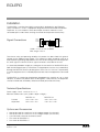
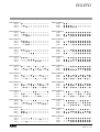
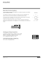
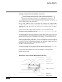
BOLERO
Instruction Manual
Manuel d'instruction
Handleiding
Bedienungsanleitung
Lighting Technologies
M 1030
1106.01.030
BOLERO
Instruction
Manual
Lighting Technologies
Page
1
Revision : 002
BOLERO
Summary
Installation
Signal Connections
Technical Specifications
Options and Accessories
Unpacking the desk
Precautions
Caution
Connecting to the back panel
4
4
4
4
5
5
5
5
«GRAND MASTER»
6
Manual Section
6
Flash Keys
Generating Manual Output
Dual Preset
Effect Section
The Channel Buttons
Speed Control
START/STEP Button
Level Control
ON/OFF Button
Direction Button
Mode Button
6
7
8
9
9
9
9
9
10
10
10
Remote Control (option)
12
Analogue Output (option)
12
Analogue Output Card Installation Instruction
Selectional view of output board fitted into desk
13
13
Controls, Indicators and Connectors
15
In Case of Difficulty
16
Page
2
Revision : 002
Lighting Technologies
BOLERO
Delivery - Unpacking
Upon delivery of your equipment, open the packaging carefully and examine the
material.
If you observe any damage, contact the shipping company immediately, and have
your complaint duly recorded. You may rest assured that your equipment left the
factory in perfect condition.
Check whether what you have received is in conformity with the delivery notice, and
whether the notice is in conformity with your order.
In the event of any error, contact your shipper immediately to clarify the situation and
receive full satisfaction.
If you find nothing wrong, replace the material in the packing and store it in a warm
place, away from dust and humidity, while awaiting final installation.
Never leave the material on the worksite under any circumstance.
Generalities - Safety
The equipment is built in accordance with European safety standards and requires
imperatively a safety earth connection in compliance with local regulations.
To prevent any risk of electric shock, do not remove any cover or part of the
enclosure.
Access to internal parts is not required for normal operation.
Refer servicing to skilled and trained service personnel exclusively.
Disconnect from the power supply prior to opening for inspection or service.
WARNING ! LETHAL VOLTAGES ARE PRESENT INSIDE
Connection to an inappropriate power source may irreversibly damage the
equipment, it is the user’s responsibility to use the equipment for its intended
purpose and to check the equipment connected to it.
To obtain full benefits of the safety measures, the equipment shall be installed and
serviced by skilled and trained personnel exclusively.
Don't make any modification to the equipment.
ADB shall not accept any liability for material damages or injuries which may result
from unauthorised modifications.
Important Notice for Power Cables
Power supply cables and connectors are an important part of your equipment and
contribute to its safety.
• always use an isolator or main circuit-breaker, or main fuses to interrupt the link;
never pull on the cable
• do not damage the cable nor the connectors in any way, check them at each
installation or at regular intervals in a permanent installation
• do not tie together power supply cables and signal cables
Lighting Technologies
Page
3
Revision : 002
BOLERO
Installation
The BOLERO is a professional lighting control desk, developed as per EN60950
safety standard. It is a class 1 equipment designed and manufactured to EN60950.
To prevent any risk of electric shock do not open the desk, there are no user
serviceable parts inside. Refer servicing to trained service personnel exclusively.
Signal Connections
GND
1
DATA - 2
DATA + 3
4
5
O
O
O
O
O
O 1 GND
O 2 DATA O 3 DATA +
O4
O5
XLR5-MX
dimmer dependent
Cable : x 2 x 0,34 mm shielded
Max. length : 250 m
2
To enhance safety and operating reliability this product has been fitted with galvanic
isolation on the DMX512/1990 output. This isolation has been tested for 500V dc in
order to prevent grounding loop problems or to transfer low voltages occasionally present
on some signals to controls or other signal connectors accessible to the user.
It is absolutely forbidden to apply any voltage to the connections of the BOLERO (Aux,
DMX and Analogue outputs). Connections to inappropriate sources may inadvertently
damage the BOLERO and may be dangerous to the user. It is the user's responsibility
to use the equipment for it's intended purpose and to check the equipement connected
to it.
The BOLERO is a professional equipment developed with simplicity of use in mind.
However, in order to fully benefit from the designed in safety features, the equipment
shall be installed and serviced by skilled and trained personnel exclusively.
Technical Specifications
Power supply : 220V - 240V, 50 Hz ± 1 %.
Mechanical dimensions (mm) (width x depth x height) :
Packed
Unpacked
BOLERO 12
530 x 340 x 130
500 x 315 x 118
BOLERO 24
760 x 340 x 130
730 x 315 x 118
Options and Accessories
•
•
•
•
•
Conversion card for 370uA or 0/+10V analogue output (24 channels).
Conversion card for 370uA or 0/+10V analogue output (48 channels).
5 pin DIN male connector for remote control.
Dust cover for BOLERO 12.
Dust cover for BOLERO 24.
Page
4
Revision : 002
Lighting Technologies
BOLERO
Unpacking the desk
After removing the desk from it's box, check that the following items are included :
• 1 BOLERO desk
• 1 User manual (this document)
• 1 * 5 pin XLR male connector for DMX512/1990 signal
If any of the previous items are missing contact your supplier immediately. Retain the
box and packing material for any future transportation or storage of the desk.
Precautions
WARNING
To prevent fire or shock hazard, do not
expose these units to rain or moisture.
Caution
Disconnect the mains plug from the supply socket when not in use.
Avoid using the desk under the following conditions :
• Extremely hot, cold or humid places,
Ambient temperature
Storage
Maximum gradient
Humidity
:
:
:
:
0 to 40 °C
- 10 to 50 °C
5 °C per hour
30 % to 70 % RH without condensation.
• Dusty places,
Be careful of moisture condensation.
Avoid using the desk immetiately after moving from a cold place to a warm place or
soon after heating a room which was cold.
Handle the desk carefully.
• Do not place anything heavy on the desk.
• Do not place anything which could spill and cause problems on or near the desk.
Connecting to the back panel
The only connection required to operate the desk is for the power cable to be plugged
into the power socket on the back panel, and the power plug to be connected to a
suitable mains outlet. However if any output is needed then a suitable cable needs to
be linked from the DMX512/1990 output socket to a recommended DMX512/1990
controlled dimmer unit.
Lighting Technologies
Page
5
Revision : 002
BOLERO
«GRAND MASTER»
USING THE Grand Master SECTION
The Grand Master section controls the output of the desk.
If the «ON/OFF» button is pressed then all output from the desk is off, and the LED
above the button is off.
A second press of the button restores the output, and illuminates the LED.
The Grand Master fader controls the overall output level of the desk.
In it's lowest position (0) the output is off, as if the «ON/OFF» button had been
pressed. In it's highest position (10) output is at maximum.
Any position beween these two will provide an output of between 0% and 100%
depending on the position of the fader.
Manual Section
Flash Keys
Each pair or MANUAL section faders has associated with it a «FLASH» button.
Each «FLASH» button will flash the output of it's associated channel, and the
corresponding LED will light.
The output from a«FLASH» button press is dependant only on the position of the
Grand Master fader, and whether the Grand Master section «ON/OFF» button is on.
Page
6
Revision : 002
Lighting Technologies
BOLERO
Generating Manual Output
Each group of Preset faders has a master control fader and on/off button. The master
for Preset B works in reverse of that for Preset A, i.e. 100% is at the bottom and 0% is
at the top of its travel, for Preset B. The «ON/OFF» buttons work in a similar fashion to
the Grand Master «ON/OFF» button, in that they control whether the output from their
respective Preset group is blacked out (LED off) or not.
Assuming that all the Preset faders are at the bottom of their travel and that the Preset
A master fader is set to a value above 0 and that the «ON/OFF» button has not been
pressed, i.e. the LED is on. Also that the Grand Master fader is above 0 and it's
associated «ON/OFF» button has not been pressed. Moving a Preset fader off of 0 will
produce an output on that channel. If a dimmer unit is connected to the output the
lamp on that channel will light. Increasing the level of the Preset fader will increase the
light level of the lamp. Once the output level increases above a 10% the LED below the
Preset fader will light. Also if the Preset master fader is over 10% the Preset A bank
LED will light to show that the Preset is active. Moving more Preset faders will light
more lamps on the corresponding output channels as well as the LED's below the
faders on the desk.
Once a display of illuminated lamps has been created on the output the level of these
lamps may be varied in several ways.
• By moving each individual fader to vary it's output level.
• By changing the position of the Preset master fader to after the output level of all
the active Preset channels.
• By moving the Grand Master fader to change the output level of the desk.
The action of the master fader is governed by the setting of the manual timer control.
If we consider the movement of the master fader, and call the start position posn. A
and the end position posn. B. If the timer is set to 0 then the output will change in time
with the movement of the master fader. If the timer is set to anything else then the
output will change from the posn. A to posn. B fader setting's in the time set. Whilst the
output is still changing from one setting to the other the RUN A LED above the timer will
flash to show that the fade is still in progress. If the master fader is moved again, say to
posn. C, whilst a fade is in progress then the fade restarts, at the new time setting (if
changed), from posn. B to posn. C.
Note :
If the manual timer control is moved whilst a fade is in progress then the fade will restart
from it's current position to it's final position but will take into account the percentage
complete of the current fade i.e. If the fade was 50% complete and the manual timer
was moved to 18 seconds the fade would take a further 9 seconds to complete.
At any stage the output may be blacked out by using either of the «ON/OFF»
buttons, in the maunal Preset A, manual Preset B or the Grand Master sections. A
Blackout state may also be achieved by moving either master fader to 0. If a
blackout is initiated, by pressing one of the relevant «ON/OFF» buttons, whilst a fade
is in progress, the fade will continue to it's end.
Lighting Technologies
Page
7
Revision : 002
BOLERO
Dual Preset
Dual Presets allow for the creation of two output settings on two different banks of
faders, Preset A and Preset B. Either or both presets may be output from the desk with
the highest value of each channel taking precedence.The active Preset(s) are shown
by illuminating the corresponding LED. Either Preset may be blacked out using the
corresponding «ON/OFF» button and the output level of each Preset is determined by
the two master faders, labelled A and B.
Assume an output pattern has been created on both banks of faders and that Preset A
is currently active, i.e. both master faders are at the top of their travel, and the timer
control is set to 10 secs. A dip-less cross fade can be made from Preset A to Preset B
simply by sliding both master faders together from the top to the bottom of their travel.
Preset A will fade out as Preset B fade's in. The total fade will take 10 seconds and
during this time both the RUN A and RUN B LED's above timer control will flash showing
a fade is in progress. Once complete a new output pattern may be created on the
Preset A bank of faders and the process reversed, i.e. the master faders moved from
the bottom to the top of their travel, to fade the new pattern in.
Note :
A dip-less cross fade will constantly compare the value of the two faders relating to
each channel. The highest value will always take precedence, i.e. the output value will
never fall below that of the initial fader value.
Page
8
Revision : 002
Lighting Technologies
BOLERO
Effect Section
A pre-programmed chase sequence may be selected from those available. The patterns
available depend on whether a BOLERO 12 or a BOLERO 24 is being used. For the
BOLERO 12 chase patterns 1 to 12 are available. On the BOLERO 24 patterns 1 to 24
may be used. The channels over which the chase runs may be individually selected.
The Effect section controls use is detailed below.
The Channel Buttons
This button selects the channels over which the chosen pattern will operate. After
pressing the button the manual section LEDs and flash buttons are used to select
which channels are incorporated. Pressing a flash key will toggle that channel between
being in or out of the chase range. If the LED is lit then that channel will be included.
The desk will remember not only whith channels to include but in which order they
were selected, i.e. if the flash buttons were pressed in the following order 1-4-6-2-912-10 then the chase pattern would run through the channels in that order.
This configuration may now be used by pressing the «CHANNELS» button again. The
channel range will not change until the button is pressed.
Speed Control
This control is used to select the step rate of the Effect section output. It's range covers
approximately one step every 0,1 second, at the top of it's travel (MAX.) to one step
every 2 seconds near the bottom of it's travel. If the control is moved to the very
bottom of it's travel, then the chase will be HELD and the output can be stepped
though manuallly using the «START/STEP» button. The LED above the control will flash
in time with the selected chase speed (one flash per step) unless it is in the manual step
mode in which case the LED will be on only while the « START/STEP» button is pressed.
START/STEP Button
If the SPEED control is in the HOLD position then the «START/STEP» button will advance
the current Effect sequence one step for every press of the button. If the SPEED control
is in any other position then pressing the «START/STEP» button will have a different
use. In this instance when the button is pressed the current Effect will be held. This is
confirmed by the SPEED LED being lit continuously. The blackout will be enabled (the
on/off LED will go off), and the Effect will be reset to it's first step.
A Second press of the button will restart the Effect from the beginning and remove the
blackout. If whilst the Effect is held the «ON/OFF» button is pressed instead of the
«START/STEP» button then the chase output will be turned on but the chase would
remain held.
Level Control
The LEVEL control regulates the output level from the Effect section.
If the «ON/OFF» button has been pressed then this control makes no difference to the
visible output of the desk.
Lighting Technologies
Page
9
Revision : 002
BOLERO
ON/OFF Button
All the «ON/OFF» buttons on the desk have the same basic effect.
They remove the effect of their associated section from the output on the stage, whithout
effecting the processing of that section, i.e. in the Effect section if the «ON/OFF» button
is pressed then the sections effect on the stage output is lost but the chase sequence
will continue. A press of the «ON/OFF» button is confirmed by it's LED going out,
another press of the button will reverse this action. To confirm, when the LED is OFF
then the on/off is in operation, i.e. no output from that section will reach the stage. All
«ON/OFF» buttons act with a toggle action, i.e. one press for ON, the next press for
OFF, press again for ON…
Direction Button
This button (shown as two arrow heads) has two LED's associated with it. One indicates
a right to left (BACKWARDS) direction, the other a left to right (FORWARDS) direction.
Pressing the direction button will cause the current Effect to travel from left to right
(FORWARDS LED lit). Another press will cause the Effect to travel from right to left
(BACKWARDS LED lit). A further press will cause the Effect to «bounce», to travel
alternately backwards then forwards (both LED's are lit). Pressing the key will cycle
through these three options.
Mode Button
This button allows the selection of the required chase pattern.
Simply press the «MODE» button once and then the «FLASH» button corresponding to
the pattern required. On both the BOLERO 12 and BOLERO 24 «FLASH» buttons 1 to
12 select chase patterns 1 to 12. On the BOLERO 24 the additional «FLASH» buttons
are used to select patterns 13 to 24 on «FLASH» buttons 13 to 24 respectively.
Those patterns are shown opposite :
●
=
Light ON
❍
=
Light OFF
Page
10
Revision : 002
Lighting Technologies
BOLERO
Chase Pattern 1
Step 1
● ❍ ❍ ❍ ❍ ❍ ❍ ❍ ❍ ❍ ❍ ❍
Step 2
❍ ● ❍ ❍ ❍ ❍ ❍ ❍ ❍ ❍ ❍ ❍
Step 3
❍ ❍ ● ❍ ❍ ❍ ❍ ❍ ❍ ❍ ❍ ❍
Chase Pattern 13
Step 1
● ● ❍ ❍ ❍ ❍ ❍ ❍ ❍ ❍ ❍ ❍
Step 2
● ● ● ● ❍ ❍ ❍ ❍ ❍ ❍ ❍ ❍
Step 3
● ● ● ● ● ● ❍ ❍ ❍ ❍ ❍ ❍
Chase Pattern 2
Step 1
● ● ❍ ❍ ❍ ❍ ❍ ❍ ❍ ❍ ❍ ❍
Step 2
❍ ● ● ❍ ❍ ❍ ❍ ❍ ❍ ❍ ❍ ❍
Step 3
❍ ❍ ● ● ❍ ❍ ❍ ❍ ❍ ❍ ❍ ❍
Chase Pattern 14
Step 1
❍ ● ● ● ● ● ● ● ● ● ● ●
Step 2
● ❍ ● ● ● ● ● ● ● ● ● ●
Step 3
● ● ❍ ● ● ● ● ● ● ● ● ●
Chase Pattern 3
Step 1
● ● ● ❍ ❍ ❍ ❍ ❍ ❍ ❍ ❍ ❍
Step 2
❍ ● ● ● ❍ ❍ ❍ ❍ ❍ ❍ ❍ ❍
Step 3
❍ ❍ ● ● ❍ ❍ ❍ ❍ ❍ ❍ ❍ ❍
Chase Pattern 15
Step 1
❍ ❍ ● ● ● ● ● ● ● ● ● ●
Step 2
● ❍ ❍ ● ● ● ● ● ● ● ● ●
Step 3
● ● ❍ ❍ ● ● ● ● ● ● ● ●
Chase Pattern 4
Step 1
● ● ❍ ❍ ❍ ❍ ❍ ❍ ❍ ❍ ❍ ❍
Step 2
❍ ❍ ● ● ❍ ❍ ❍ ❍ ❍ ❍ ❍ ❍
Step 3
❍ ❍ ❍ ❍ ● ● ❍ ❍ ❍ ❍ ❍ ❍
Chase Pattern 16
Step 1
❍ ❍ ❍ ● ● ● ● ● ● ● ● ●
Step 2
● ❍ ❍ ❍ ● ● ● ● ● ● ● ●
Step 3
● ● ❍ ❍ ❍ ● ● ● ● ● ● ●
Chase Pattern 5
Step 1
● ● ● ❍ ❍ ❍ ❍ ❍ ❍ ❍ ❍ ❍
Step 2
❍ ❍ ❍ ● ● ● ❍ ❍ ❍ ❍ ❍ ❍
Step 3
❍ ❍ ❍ ❍ ❍ ❍ ● ● ● ❍ ❍ ❍
Chase Pattern 17
Step 1
❍ ❍ ● ● ● ● ● ● ● ● ● ●
Step 2
● ● ❍ ❍ ● ● ● ● ● ● ● ●
Step 3
● ● ● ● ❍ ❍ ● ● ● ● ● ●
Chase Pattern 6
Step 1
● ❍ ❍ ● ❍ ❍ ● ❍ ❍ ● ❍ ❍
Step 2
❍ ● ❍ ❍ ● ❍ ❍ ● ❍ ❍ ● ❍
Step 3
❍ ❍ ● ❍ ❍ ● ❍ ❍ ● ❍ ❍ ●
Chase Pattern 18
Step 1
❍ ❍ ❍ ● ● ● ● ● ● ● ● ●
Step 2
● ● ● ❍ ❍ ❍ ● ● ● ● ● ●
Step 3
● ● ● ● ● ● ❍ ❍ ❍ ● ● ●
Chase Pattern 7
Step 1
● ❍ ❍ ❍ ● ❍ ❍ ❍ ● ❍ ❍ ❍
Step 2
❍ ● ❍ ❍ ❍ ● ❍ ❍ ❍ ● ❍ ❍
Step 3
❍ ❍ ● ❍ ❍ ❍ ● ❍ ❍ ❍ ● ❍
Chase Pattern 19
Step 1
❍ ● ● ❍ ● ● ❍ ● ● ❍ ● ●
Step 2
● ❍ ● ● ❍ ● ● ❍ ● ● ❍ ●
Step 3
● ● ❍ ● ● ❍ ● ● ❍ ● ● ❍
Chase Pattern 8
Step 1
● ❍ ❍ ● ● ❍ ❍ ● ● ❍ ❍ ●
Step 2
● ● ❍ ❍ ● ● ❍ ❍ ● ● ❍ ❍
Step 3
❍ ● ● ❍ ❍ ● ● ❍ ❍ ● ● ❍
Chase Pattern 20
Step 1
❍ ● ● ● ❍ ● ● ● ❍ ● ● ●
Step 2
● ❍ ● ● ● ❍ ● ● ● ❍ ● ●
Step 3
● ● ❍ ● ● ● ❍ ● ● ● ❍ ●
Chase Pattern 9
Step 1
❍ ❍ ❍ ❍ ❍ ● ● ❍ ❍ ❍ ❍ ●
Step 2
● ● ❍ ❍ ❍ ❍ ● ● ❍ ❍ ❍ ❍
Step 3
❍ ● ● ❍ ❍ ❍ ❍ ● ● ❍ ❍ ❍
Chase Pattern 21
Step 1
❍ ● ● ❍ ❍ ● ● ❍ ❍ ● ● ❍
Step 2
❍ ❍ ● ● ❍ ❍ ● ● ❍ ❍ ● ●
Step 3
● ❍ ❍ ● ● ❍ ❍ ● ● ❍ ❍ ●
Chase Pattern 10
Step 1
● ❍ ❍ ❍ ❍ ● ● ❍ ❍ ❍ ❍ ●
Step 2
❍ ● ● ❍ ❍ ❍ ❍ ● ● ❍ ❍ ❍
Step 3
❍ ❍ ❍ ● ● ❍ ❍ ❍ ❍ ● ● ❍
Chase Pattern 22
Step 1
❍ ● ● ● ● ❍ ❍ ● ● ● ● ❍
Step 2
❍ ❍ ● ● ● ● ❍ ❍ ● ● ● ●
Step 3
● ❍ ❍ ● ● ● ● ❍ ❍ ● ● ●
Chase Pattern 11
Step 1
● ❍ ❍ ❍ ❍ ❍ ❍ ❍ ❍ ❍ ❍ ❍
Step 2
● ● ❍ ❍ ❍ ❍ ❍ ❍ ❍ ❍ ❍ ❍
Step 3
● ● ● ❍ ❍ ❍ ❍ ❍ ❍ ❍ ❍ ❍
Chase Pattern 23
Step 1
❍ ● ● ● ● ❍ ❍ ● ● ● ● ❍
Step 2
● ❍ ❍ ● ● ● ● ❍ ❍ ● ● ●
Step 3
● ● ● ❍ ❍ ● ● ● ● ❍ ❍ ●
Chase Pattern 12
Step 1
❍ ❍ ❍ ❍ ● ❍ ❍ ❍ ❍ ❍ ❍ ❍
Step 2
❍ ❍ ❍ ❍ ❍ ❍ ❍ ❍ ● ❍ ❍ ❍
Step 3
❍ ❍ ● ❍ ❍ ❍ ❍ ❍ ❍ ❍ ❍ ❍
Chase Pattern 24
Step 1
❍ ● ● ● ● ● ● ● ● ● ● ●
Step 2
❍ ❍ ● ● ● ● ● ● ● ● ● ●
Step 3
❍ ❍ ❍ ● ● ● ● ● ● ● ● ●
Lighting Technologies
Page
11
Revision : 002
BOLERO
Remote Control (option)
One of the options available for the BOLERO is the ability to remotely use the Effect
section START/STEP button.
AUX DIN 5
This operation is identical to that button on the desk itself, and is detailed in the
relevant section of the manual. No button has preference over the other.
The remote control is plugged into the AUX socket on the back panel. The remote
START/STEP button will short pins 2 and 4 when used.
If either of the START/STEP buttons (desk or remote) are pressed and held the
operation of the other button is not impaired, as it is the initial press that initiates the
action.
4
2
1
5
3
2 = STEP
4 - 5 = 0V
BOLERO
(1)
START/STEP
O1
O2
O3
O4
O5
(1) any type of switch
Analogue Output (option)
The option of analogue output, in addition to the standard
DMX512/1990 output, is available in one of two formats.
Either as a current driven output (0 to 370uA)
or as a voltage driven output (0 to +10V).
If the analogue output option is fitted then the
output format will be marked on the back panel,
with a mark in the appropriate box.
Page
12
Revision : 002
0-370µA
0-10V
Lighting Technologies
BOLERO
Analogue Output Card Installation Instruction
This assembly and desk contain static sensitive components.
Installation should be undertaken using appropriate precautions.
Turn the desk over onto it ' s front and remove the rear cover plate. Put this and the
screws carefully to one side, to refit later.
Using a sharp scalpel, or similar, cut out either one or both of the analogue output
connector positions in the rear connector panel of the control desk. Make sure the
scalpel blade is kept tight against the metal chassis to ensure a clean cut edge is
achieved.
Carefully remove the analogue output card from it’s anti-static protective bag.
Remove the small hexagonal screws in the front face of the twenty five way output
connectors and put carefully to one side.
The analogue board is normally configured as voltage driven outputs (0 to +10V). If you
wish to configure it as current driven outputs (0 to 370µA), you must replace the 120 Ω
resistors by the 27K resistors, delivered with the board, as 16-contact chips (DIL's)
Hold the analogue board upside down, i.e. with the components facing the table top
and the flying lead running under the board.Insert the output connector(s) through the
cut-out(s) in the rear connector panel and push the two plastic support pillars firmly
through the two mating holes in the main board in the desk.
The pillars should snap into place.
The small hexagonal screws removed earlier can now be screwed back into the output
connector(s), through the rear panel, to hold the board securely in place.
Plug the flying lead connector into the ten way header on the master board.
Replace the rear cover.
Selectional view of output board fitted into desk
Plastic rivets
Analogue board
Metal chassis
Hexagonal screws
Output connector(s)
Main board
Support pillars
Lighting Technologies
Page
13
Revision : 002
BOLERO
Rear View
1
2
3
4
5
Front View
19 20
13 14 15 16
6
11 12
21
29 30
24
25
26
27
7
8
9
Page
14
Revision : 002
10
17 18
22 23
28
31
Lighting Technologies
BOLERO
Controls, Indicators and Connectors
Rep.
1
2
3
4
5
6
7
8
9
10
11
12
13
14
15
16
17
18
19
20
21
22
23
24
25
26
27
28
29
30
31
Lighting Technologies
Description
POWER socket (230 V)
DMX 512/1990 output connector (5 pin female 'D' type XLR)
AUX input socket (5 pin female DIN connector)
Analogue output connectors (optional)
SERIAL No --Preset A manual faders
Preset B manual faders
Preset LED indicators
Preset Flash buttons
Manual section TIMER fader
Preset A RUN LED
Preset B RUN LED
Preset A ON/OFF LED
Preset B ON/OFF LED
Preset A ON/OFF button
Preset B ON/OFF button
Preset A section fader
Preset B section fader
Effect's section ON/OFF LED
Effect's section ON/OFF button
Effect's section cross-fade RUN LED
Effect's section SPEED fader
Effect's section LEVEL fader
Effect's section Direction indicator LED's
Effect's section DIRECTION button
Effect's section MODE button
Effect's section CHANNELS button
Effect's section START/STEP button
(operation depends on position of SPEED fader)
Master section ON/OFF LED
Master section ON/OFF button
Desk output Master level fader
Page
15
Revision : 002
BOLERO
In Case of Difficulty
FAULT
POSSIBLE REMEDIES
Desk fails to come on.
Is power supply plugged into desk correctly ?
Is power supply connected to mains supply ?
Is mains supply switched on ?
Manual section faders do not produce an output
when pushed up.
Has the Manual section been blacked out ? (ON/OFF)
Has the Master section been blacked out ? (ON/OFF)
Is the Master section fader off of 0 ?
Manual section LED's do not mimic fader operation.
Has the Manual section been blacked out ? (ON/OFF)
Has the Master section been blacked out ? (ON/OFF)
Is the Master section fader off of 0 ?
Effects section Step button has no effect.
Speed fader not set at bottom of it's travel.
No output from Effect section.
Has the effect section been blacked out ? (ON/OFF)
Has the Master section been blacked out ? (ON/OFF)
Is the Master section fader off of 0 ?
Is the Level fader off of 0 ?
Page
16
Revision : 002
Lighting Technologies
M-1030-4L-06h
Belgium
N.V. ADB-TTV Technologies S.A.
(Group Headquarters)
Leuvensesteenweg 585,
B-1930 Zaventem
Tel : 32.2.709.32.11
Fax : 32.2.709.32.80
E-Mail : [email protected]
Deutschland
ADB GmbH
Dieselstraße 4,
D-63165 Mühlheim am Main
Tel : 49.6108.91.250
Fax : 49.6108.91.25.25
E-Mail : [email protected]
France
ADB S.A.S.
Sales office:
168/170, boulevard Camélinat
F-92240 Malakoff
Tel : 33.1.41.17.48.50
Fax : 33.1.42.53.54.76
E-Mail : [email protected]
Factory & group logistics centre:
Zone industrielle Rouvroy
F-02100 Saint-Quentin
Tel : 33.3.23.06.35.70
Fax : 33.3.23.67.66.56
E-Mail : [email protected]
ADB - Your Partner for Light - ISO 9001 : 2000 certified
Lighting Technologies
www.adblighting.com