1
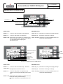
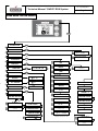
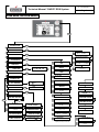
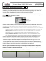
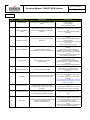
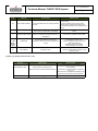
Technical Manual “RAPID” RDS System Rev.2 of 05/06/2012 Technical Manual “RAPID” RDS System Ver. 2 of 28/05/2012 Page 3 INDEX - RAPID DESCRIPTION DISPLAY..................................................................................PAGE 4 - USER MENU FOR SERIES AIR...................................................................................PAGE 5 - USER MENU FOR SERIES FLOW...............................................................................PAGE 6 - USER MENU FOR SERIES HYDRO............................................................................PAGE 7 - OPERATIONAL STATUS OF A PELLET STOVE WITH RDS SYSTEM......................PAGE 8 - PASSWORD UTILITY FOR INSTALLER......................................................................PAGE 9 - INSTALLER MENU: FACTORY SETTINGS (TF) FOR GAMMA AIR AND FLOW.......PAGE 9 - INSTALLER MENU: FACTORY SETTINGS (TF) FOR GAMMA HYDRO...................PAGE 11 - RDS SYSTEM ADJUSTMENT PROCEDURE............................................................PAGE 14 - ALLARMS.....................................................................................................................PAGE 15 - CIRCUIT DIAGRAM AIR BASE...................................................................................PAGE 17 - CIRCUIT DIAGRAM AIR FLOW...................................................................................PAGE 17 - HYDRO CIRCUIT DIAGRAM FOR MODELS WHICH CANNOT HAVE.....................PAGE 18 OPTIONAL DEL SANITATION KIT - HYDRO CIRCUIT DIAGRAM FOR MODELS WITH THE KIT ...................................PAGE 18 OPTIONAL SANITATION - SUMMARY TABLE CARD COMPATIBILITY - DISPLAY – FIRMWARE.....................PAGE 19 - PROBLEM RESOLUTION...........................................................................................PAGE 20 Ver. 2 of 28/05/2012 Technical Manual “RAPID” RDS System Page 4 RAPID DISPLAY DESCRIPTION Maintenance advice Calender CHANNELLING function AUTOMATIC / Clock CHANNELLING function MANUAL / Active chrono Work power Ambient temperature RDS function de-activated Stove status RDS Display for stoves of the AIR - FLOW -BOX series in STAND-BY mode BASIC mode ADVANCED mode Button “1” : access to “Set environment“ and adjustment Press key "1" : pushbutton for scrolling and changing settings Button “2” : access to “Set power“ and adjustment Press key "2" : scroll button and change of settings Button “OK”: brief pressure on the button for confirmation and return to the main screen; pressure on the button of 3 seconds duration for lighting and extinguishing stove. Press "OK" key : pushbutton to access the ENTER menu and confirm the selected settings. Water heater temperature Timetable Ambient temperature Stove statu Stove status Active cleaner Summer Working circulator Heating RDS system de-activated RDS display for HYDRO series stoves in STAND-BY mode ADVANCED mode BASIC mode Button “1” : access to “Set environment temp. - Set water heater temp.” and adjustment with buttons 1 and 2. Press key "1" : pushbutton for scrolling and changing settings Button “2” Press "OK" key : pushbutton to access the ENTER menu and confirm the selected settings. : access to “Set power“ and adjustment with buttons 1 and 2 (only Min and Max power can be set) Button “OK”: brief pressure on the button to confirm and return to the main screen; pressure lasting 3 seconds on the button for switching stove on and off. Press key "2" : scroll button and change of settings Winter Sanitizer us Ver. 2 of 28/05/2012 Technical Manual “RAPID” RDS System Page 5 USER MENU FOR AIR SERIES OK P2 P1 STOVE STATUS OK SET AMBIENT OK SET POWER OK OK P2 P2 P1 P2 OK P2 P1 P2 OK STOPWATCH P2 P1 P2 OK TIME TRIAL P1 OK IT - EN - DE - FR P2 ACTIVATE SILENCE OK ON - OFF P2 ACTIVATE SYSTEM AUTO CONTROL ON - OFF OK P2 VIEW FACTORY SETTINGS P2 P1 P2 OK see WORKING HOURS P2 P1 P2 SET AIR / PELLETS P2 DAY OF WEEK MON - SUN HOUR OK M/S FLOW OK G/M EXTRACTOR MINUTE ACTIVE TIME TRIAL ON - OFF SMOKE T °C START PRG 1 MACHINE STATUS P1 STOP PRG 1 SET REAL FLOW OK SET PELLET % -5 to +5 P1 TOTAL HOURS SET FLOW % -5 to +5 P2 DAY OF WEEK MON - SUN ON - OFF P1 OK P2 YEAR OK P1 OK P1 P2 P1 OK P2 OK P2 see CALIBRATIONS SET POWER 1-2-3-4-5 P1 OK P1 S.C. SYSTEM MONTH OK P2 P2 P2 P1 SILENCE DAY P2 P2 OK P2 P1 P1 P1 CLIMATE COMFORT CONSOLE SENSOR READING ON - OFF OK P2 LANGUAGE SET TEMPERATURE AMBIENT EXT - 6 - ... - 40 - MAN COUNTER HOURS P2 SET POWER 1-2-3-4-5 P1 P2 P1 P1 P2 CLEAR WORKING HOURS PWD 35 OK BOARD T °C OK P1 PARTIAL HOURS AIR FLOW METER T °C OK P1 SET TEMP AMBIENT EXT - 6 - ... - 40 - MAN Repeat the procedure for adjusting the subsequent time trials P1 P2 CLIMATE COMFORT OFF - 1 - ... - 20 OK P1 P2 CLIMATE COMFORT DELAY 01 - 09 Ver. 2 of 28/05/2012 Technical Manual “RAPID” RDS System Page 6 USER MENU FOR FLOW SERIES OK P2 P1 STOVE STATUS OK SET AMBIENT OK SET POWER OK OK P2 P2 P1 P2 OK P2 P1 P2 OK STOPWATCH P1 P2 OK P1 OK IT - EN - DE - FR P2 ACTIVATE SYSTEM AUTO CONTROL ON - OFF OK P2 P2 P1 P2 VIEW FACTORY SETTINGS OK P2 P1 P2 OK see WORKING HOURS P2 P1 P2 SET AIR / PELLETS P2 YEAR DAY OF WEEK MON - SUN HOUR OK M/S FLOW OK G/M EXTRACTOR MINUTE ACTIVE TIME TRIAL ON - OFF SMOKE T °C START PRG 1 MACHINE STATUS P1 STOP PRG 1 SET REAL FLOW OK SET PELLET % -5 to +5 P1 TOTAL HOURS P2 DAY OF WEEK MON - SUN ON - OFF P1 OK SET FLOW % -5 to +5 COUNTER HOURS AIR FRONT/REAR P2 SET POWER 1-2-3-4-5 P1 P2 P2 SET TEMP. AMBIENT EXT - 6 - ... - 40 - MAN P1 CLEAR WORKING HOURS PWD 35 OK BOARD T °C OK P1 PARTIAL HOURS P2 AIR FLOW METER T °C OK P1 P1 CUBIC CAPACITY P2 OK P1 OK P2 SET POWER 1-2-3-4-5 P1 OK P1 S.C. SYSTEM P1 MONTH OK P2 P2 OK P2 SET DUCTED # OFF - EST - 6 - ... - 40 - MAN OK CHANNELLED P2 P2 P1 see CALIBRATIONS DAY P2 P2 OK P2 P1 P1 P1 CLIMATE COMFORT P1 OK P2 LANGUAGE CONSOLE SENSOR READING ON - OFF OK P2 TIME TRIAL SET TEMPERATURE AMBIENT EXT - 6 - ... - 40 - MAN OK P1 P2 SET DUCTED OFF - EST - 6 - ... - 40 - MAN Repeat the procedure for adjusting the subsequent time trials P1 P2 CLIMATE COMFORT OFF - 1 - ... - 20 OK P1 P2 CLIMATE COMFORT DELAY 01 - 09 Ver. 2 of 28/05/2012 Technical Manual “RAPID” RDS System Page 7 USER MENU FOR HYDRO SERIES OK P2 P1 STOVE STATUS OK SET AMBIENT OK SET POWER OK OK P2 P2 P1 P2 OK P2 P1 P2 OK STOPWATCH P1 P2 OK P1 P2 OK P1 SET WINTER/SUMMER OK ON - OFF P2 P1 OK SET POT. FAN P2 OFF - 1 - 2 - 3 P2 P1 ACTIVATE SYSTEM AUTO CONTROL ON - OFF OK P2 P2 P1 see CALIBRATIONS P2 VIEW FACTORY SETTINGS OK P2 P1 P2 OK see WORKING HOURS P2 P1 P2 SET AIR / PELLETS P1 P1 P2 DAY OF WEEK MON - SUN M/S FLOW HOUR OK G/M EXTRACTOR OK SMOKE T °C MINUTE ACTIVE TIME TRIAL ON - OFF H2O PRESSURE START PRG 1 MACHINE STATUS P1 STOP PRG 1 SET REAL FLOW DAY OF WEEK MON - SUN ON - OFF P2 P1 PARTIAL HOURS AIR FLOW METER T °C OK P1 COUNTER HOURS SET PELLET % -5 to +5 SET FLOW % -5 to +5 P2 YEAR P1 OK P2 SET POWER MIN - MAX P1 OK TOTAL HOURS OK P1 P2 OK LANGUAGE P2 MONTH OK P2 P1 P2 OK P2 S.C. SYSTEM WATER HEATER SET 10 - 70 OK P2 VENTILATION DAY OK P2 WINTER/SUMMER P1 OK P2 CLIMATE COMFORT CONSOLE SENSOR READING ON - OFF OK P2 TIME TRIAL SET TEMPERATURE AMBIENT EXT - 6 - ... - 40 - MAN SET TEMPERATURE AMBIENT EXT - 6 - ... - 40 - MAN BOARD T °C Repeat the procedure for adjusting the subsequent time trials P1 CLEAR WORKING HOURS PWD 35 OK P1 P2 CLIMATE COMFORT OFF - 1 - ... - 20 OK IT - EN - DE - FR P1 P2 P1 P2 CLIMATE COMFORT DELAY 01 - 09 1 2 3 4 4 ON / PRE-HEATING DELAY FLAME THIS FLAME WORK AIR MODULATION FAN – START DELAY TF15/TF45 if T. SMOKE < TF07 after RESTART BLOCKAGE 7 4 4 AIR MODULATION with display of "AIR FLOW METER FAILURE 09." WORK With RDS disabled After switching by OK Flow meter failure or disconnection if Amb. T. > SET Amb. T. with CLIMATE COMFORT active if T. SMOKE> TF15 & T. SMOKE < TF07 After RESTART BLOCKAGE. TF39 NONE CLIMATE COMFORT DELAY SELECTED ON MENU TF07/TF15/TF45 TF12/TF11 WORKING with a symbol on display indicating RDS off WORK MODULE ECO STOP FAN RESTART DELAY ACTIVE CLEANER COLOUR BLUE (CURSIVE) --> Function phases with relation to the HYDRO range stoves and related involved parameters. Legend: 7 ECO AIR STOP ATTEMPT RESTART FINAL CLEANING NONE With Keystroke P3 6 TURNING OFF each CLEANING FREQUENCY CLEANING BRAZIER WORK MODULE 4 TF13 TF12 NONE CLEANING with CLEANER Each CADENCE CLEANING if H2O and T.AMB reached 5 WATER MODULE AIR MODULE WORK THIS FLAME 4 NONE NONE if Amb. T. > SET Amb. T. TF09 TF05 if T.H2O > SET T.H2O After MIN. START After DELTA FLAME DELAY FLAME LIGHT UP - RESET LIGHT STATUS MESSAGE DISPLAYED BRAZIER CLEANING 4 TF07/TF15 if T. SMOKE> TF15 & T. SMOKE <TF07 TF 04 TF15 if T. SMOKE <TF15 After PRE-HEATING TF15/TF46 PARAMETER INVOLVED IN CONDITION if T. SMOKE <TF15 after T. MIN. POWER CONDITION WORK MODULE WATER MODULATION 0 Code STATUS STATUS TF16/19/22/25/28 TF18/21/24/27/30 TF06 TF33/34/35/36/37 TF33-37 NONE (NON-OPERATING STATUS) NONE (NON-OPERATING STATUS) NONE (NON-OPERATING STATUS) TF15/TF06/TF46 TF14/TF18/TF27orTF21 TF12 /TF14/TF11 TF13/TF14/TF18 TF16/TF17 TF16/TF17 TF16/TF17/TF18 TF16/TF17 TF16/19/22/25/28 TF17/20/23/26/29 TF18/21/24/27/30 TF06 TF09/TF08/TF32 TF48/TF31/TF02/TF05/TF01 TF48/TF32/TF04/TF02/TF01 TF48/TF49/TF04/TF02/TF01 NONE (NON-OPERATING STATUS) PARAMETERS INVOLVED IN OFF Technical Manual “RAPID” RDS System Ver. 2 of 28/05/2012 Page 8 MEMBER OF AN OPERATING SYSTEM WITH PELLET STOVE RDS Technical Manual “RAPID” RDS System Ver. 2 of 28/05/2012 Page 9 UTILITY PASSWORD FOR INSTALLER CODE FUNCTION ACCESS TO MENU A9 Functioning parameters 35 Reset WORKING HOURS “SEE WORKING HOURS -> CANCEL HOURS” "FACTORY SETTINGS" O0 Restore parameters “FACTORY SETTINGS ->RESTORE PARAMETERS” 11 Deactivation debimeter "FACTORY SETTINGS" F1 10% canalization increase (gamma FLOW) "FACTORY SETTINGS" F2 20% canalization increase (gamma FLOW) "FACTORY SETTINGS" C2 RDS adjustment system activation “RDS ADJUSTMENT” B9 Setting hydraulic system type “HYDRAULIC SYSTEM” INSTALLER MENU: Factory setting (TF) for AIR and FLOW gamma From STAND-BY status, with a short press of the OK key you can access the selection menu icons; press key 2 to position cursor on the FACTORY SETTINGS icon and press the OK key for access. Enter the password A9 by pressing key 2 and confirm with OK. The parameters are divided into groups by type; press keys 1 and 2 to change the data; press the OK key to confirm and you will automatically move to the next digit in each unit. To exit the screens by steps, press the OK key or press the keys 1 and 2 simultaneously to go directly to the status of STAND-BY. Unit: LIGHTING TF NAME DESCRIPTION UNIT ’ sec TF01 SCREW PUMP: start flame TF02 SCREW PUMP MAX LOAD Interval time limit to make the pre-feed pellets TF04 Preheat SPARK PLUG Time for preheating heating element TF05 FLAME DELTA Increment value of the flame for passage to the next step °C TF06 FAN THRESHOLD Smoke temperature threshold to start the exchanger °C TF07 RESTART THRESHOLD Reference threshold for restarting °C TF31 LIGHTING PHASE SMOKE SPEED Smoke aspiration speed during the "FLAME DELAY" T on the screw pump motor phase "DELAY FLAME" min sec t/min Unit: FLAME PRESENT TF NAME DESCRIPTION TF08 START SCREW PUMP "ON" time of screw pump motor in the "FLAME PRESENT" phase TF09 START MINUTES Stabilization time of the flame during "FLAME PRESENT" TF32 SPEED GAS CHAMBERS Smoke aspiration speed during the "FLAME PRESENT" UNIT ' sec min t/min Technical Manual “RAPID” RDS System Ver. 2 of 28/05/2012 Page 10 Unit: CLEANING OF BRAZIER TF TF11 NAME DESCRIPTION SCREW PUMP CLEANING Cochlea motor ON times in the “CLEANING BRAZIER” phase TF12 CLEANING DURATION Duration of brazier cleaning TF13 CLEANING SCHEDULE Time interval between two cleanings of brazier TF14 CLEANING OF SMOKE ASPIRATOR Smoke aspiration speed in the "BRAZIER CLEANING" phase UNIT ' sec sec min t/min Unit: TURNING OFF TF TF15 NAME TURN OFF THRESHOLD DESCRIPTION Reference threshold for START (t smoke <= TF15) or RESTART (t smoke> TF15) UNIT ' °C Unit: POTENZE da 1 a 5 TF NAME DESCRIPTION UNIT ' COCHLEA POWER 1 ON time of the cochlea motor in work phase at power 1 TF17 FLOW POWER 1 Inlet flow to the brazier during work phase at power 1 m/s TF18 AIR SPEED P1 Primary exchanger voltage in work phase at power 1 v TF19 COCHLEA POWER 2 ON time of the cochlea motor in work phase at power 2 TF20 FLOW POWER 2 Inlet flow to the brazier during work phase at power 2 m/s TF21 AIR SPEED P2 Primary exchanger voltage in work phase at power 2 v TF22 COCHLEA POWER 3 ON time of the cochlea motor in work phase at power 3 TF23 FLOW POWER 3 Inlet flow to the brazier during work phase at power 3 m/s TF24 AIR SPEED P3 Primary exchanger voltage in work phase at power 3 v TF25 COCHLEA POWER 4 ON time of the cochlea motor in work phase at power 4 TF26 FLOW POWER 4 Inlet flow to the brazier during work phase at power 4 TF27 AIR SPEED P4 Tensione scambiatore primario in work phase at power 4 TF16 sec sec sec sec m/s v TF28 COCHLEA POWER 5 ON time of the cochlea motor in work phase at power 5 TF29 FLOW POWER 5 Inlet flow to the brazier during work phase at power 5 m/s TF30 AIR SPEED P5 Primary exchanger voltage in work phase at power 5 v sec NB: In the range of canalization which the RFS (Ravelli Flow System) uses, the ventillation value at the various power settings is not seen as it is not possible to carry out any modification to the ventillation. This is because the factory values have been set to guarantee the best output with the minimum of noise. Unit: EXTRACTOR SPEED TF NAME DESCRIPTION UNIT ' t/min TF33 SMOKE SPEED P 1 Smoke aspiration speed during work phase at power 1 TF34 SMOKE SPEED P 2 Smoke aspiration speed during work phase at power 2 t/min TF35 SMOKE SPEED P 3 Smoke aspiration speed during work phase at power 3 t/min TF36 SMOKE SPEED P 4 Smoke aspiration speed during work phase at power 4 t/min SMOKE SPEED P 5 Smoke aspiration speed during work phase at power 5 t/min TF37 Technical Manual “RAPID” RDS System Ver. 2 of 28/05/2012 Page 11 Unit: ALTITUDE TF TF38 NAME ALTITUDE DESCRIPTION Altitude above sea level UNIT ' t/min Unit: ON / OFF air flow meter TF TF39 NAME AIR FLOW METER ON / OFF DESCRIPTION "OFF" disables the RDS. "Auto Status" RDS system active with start of extractor rpm UNIT ' val Unit: FORMULA TF TF40 NAME ACTIVE FORMULA DESCRIPTION Formula OFF / Low / Low / Medium / High Draft UNIT ' str Unit: ALARMS TF TF41 NAME DESCRIPTION UNIT ' °C NO PELLETS THRESHOLD Reference threshold for reporting "NO PELLETS" TF42 MAXIMUM THRESHOLD Working limit temperature threshold TF43 ALARM DELAY ALARM DELAY TF44 BLACK OUT "BLACK OUT" activation limit seconds sec TF45 RE-LIGHTING BLOCK Delay timer START or RESTART (FAN) min °C sec TF46 T. MIN. SIGNING Timer for cleaning before "OFF" status min TF47 MINIMUM FLOW Minimum flow under which the stove recognizes clogging of the brazier or load loss m/s TF48 MAXIMUM DURATION LIGHTING UP. Maximum time for a turn ON cycle min Unit: EXTRA PARAMETERS TF NAME DESCRIPTION UNIT ' TF49 ENABLE LIGHTER Enabling/disabling resitance TF50 FREQUENCY xHZ Frequency Network TF51 DEGREES A unit of temperature °C / ° F TF52 FLUE DRAFT Option to activate to allow user to set draft rate on / off TF53 VOLT MAX Voltage for domestic power supply (230V Italy) v TF54 SERVICE HOURS Hours of operation of the stove before carrying out a special cleaning operation h on / off Hz INSTALLER MENU: Factory settings (TF) for HYDRO range From STAND-BY status, with a short press of the OK key you can access the selection menu icons; press key 2 to position cursor on the FACTORY SETTINGS icon and press the OK key for access. Enter the password A9 by pressing key 2 and confirm with OK. The parameters are divided into groups by type; press keys 1 and 2 to change the data; press the OK key to confirm and you will automatically move it to the next digit in each unit. To exit the screens by steps, press the OK key or press the keys 1 and 2 simultaneously to go directly to the status of STAND-BY. The following pages contain a decription of the Hydro parameters. Technical Manual “RAPID” RDS System Ver. 2 of 28/05/2012 Page 12 Unit: LIGHTING TF NAME DESCRIPTION T on the screw pump motor phase "DELAY FLAME" UNIT ' sec TF01 SCREW PUMP: start flame TF02 SCREW PUMP MAX LOAD Interval time limit to make the pre-feed pellets TF31 LIGHTING PHASE SMOKE SPEED Smoke aspiration speed during the "FLAME DELAY" TF04 Preheat SPARK PLUG Time for preheating heating element TF05 FLAME DELTA Increment value of the flame for passage to the next step °C TF06 PUMP THRESHOLD Smoke temperature threshold to start the exchanger °C TF07 RESTART THRESHOLD Reference threshold for restarting °C min t/min sec Unit: FLAME PRESENT TF TF08 NAME START SCREW PUMP DESCRIPTION "ON" time of screw pump motor in the "FLAME PRESENT" phase TF09 START MINUTES Stabilization time of the flame during "FLAME PRESENT" TF32 SPEED GAS CHAMBERS Smoke aspiration speed during the "FLAME PRESENT" UNIT ' sec min t/min Unit: CLEANING OF BRAZIER TF NAME DESCRIPTION UNIT ' ACTIVE CLEANER Parameters aimed at activating the cleaner str TF12 CLEANING SCHEDULE Time interval between two cleanings of brazier min TF13 CLEANING DURATION Duration of brazier cleaning (with cleaner de-activated) sec TF14 CLEANING OF SMOKE ASPIRATOR Smoke aspiration speed in the "BRAZIER CLEANING" phase TF18 SCREW PUMP CLEANING Cochlea motor ON time in the cleaning with cleaner phase TF11 TF21 CLEANER SECONDS Seconds of cleaner functioning TF27 CLEANER HITS Cleaner passes at every cleaning phase g/min sec sec num Unit: TURNING OFF TF TF15 NAME TURN OFF THRESHOLD DESCRIPTION Reference threshold for START (t smoke <= TF15) or RESTART (t smoke> TF15) UNIT ' °C Unit: SANITATION MODULE POWER TF NAME DESCRIPTION UNIT ' COCHLEA POWER MOD. Cochlea motor ON time in the work phase at MOD power. sec TF17 FLOW POWER MOD. Inlet flow to the brazier in the work phase at MOD power. m/s TF19 MIN COCHLEA POWER Cochlea motor ON time in the work phase at MIN power. sec TF20 MIN FLOW POWER Inlet flow to the brazier in the work phase at MIN power. m/s TF22 MAX COCHLEA POWER Cochlea motor ON time in the work phase at MAX power. sec TF23 MAX FLOW POWER Inlet flow to the brazier in the work phase at MAX power. m/s TF25 SANI COCHLEA POWER Cochlea motor ON time in the work phase at SANI power sec TF26 SANI FLOW POWER Inlet flow to the brazier in the work phase at SANI power m/s TF16 Technical Manual “RAPID” RDS System Ver. 2 of 28/05/2012 Page 13 Unit: EXTRACTOR SPEED TF NAME DESCRIPTION UNIT ' TF33 MOD. SMOKE P SPEED. Smoke suction speed in the work phase at MODULE power g/min TF34 MIN SMOKE P SPEED. Smoke suction speed in the work phase at MINIMUM power g/min TF35 MAX SMOKE P SPEED. Smoke suction speed in the work phase at MAXIMUM power g/min SANI SMOKE P SPEED Smoke suction speed in the work phase at SANI power g/min DESCRIPTION UNIT ' TF36 Unit: ALTITUDE TF TF38 NAME ALTITUDE Altitude above sea level meters Unit: ON / OFF air flow meter TF NAME TF39 AIR FLOW METER ON / OFF DESCRIPTION "OFF" disables the RDS. "Auto Status" RDS system active with start of extractor rpm UNIT ' val Unit: RECIPES TF TF40 NAME ACTIVE FORMULA DESCRIPTION Formula OFF / Low / Low / Medium / High Draft UNIT ' str Unit: DELTA ACCUMULATORS TF NAME DESCRIPTION UNIT ' TF54 DELTA BOILER Hysteresis which determines the Boiler water heating °C TF55 DELTA PUFFER Hysteresis which determines the water puffer heating °C Unit: ALARMS DESCRIPTION UNIT ' TF NAME TF41 NO PELLETS THRESHOLD Reference threshold for reporting "NO PELLETS" TF42 MAXIMUM THRESHOLD Working limit temperature threshold TF43 ALARM DELAY ALARM DELAY TF44 BLACK OUT "BLACK OUT" activation limit seconds sec TF45 RE-LIGHTING BLOCK Delay timer START or RESTART (FAN) min TF46 T-MINIMUM EXTINGUISHING Timer for cleaning before "OFF" status min TF47 MINIMUM FLOW m/s TF48 MAX RE-LIGHTING DURATION Maximum time for a turn ON cycle TF37 MAX H2O THRESHOLD °C °C sec Minimum flow under which the stove recognizes clogging of the brazier or load loss min Working limit water heater temperature threshold °C Unit: EXTRA PARAMETERS TF NAME DESCRIPTION UNIT ' TF49 EXCLUDE PRESSURE Exclude reading of pressure transducer TF50 FREQUENCY xHZ Frequency Network TF51 DEGREES A unit of temperature °C / ° F TF52 FLUE DRAFT Option to activate to allow user to set draft rate on / off TF53 SERVICE HOURS Hours of operation of the stove before carrying out a special cleaning operation TF30 ACTIVE FUNCTION. FAN Parameter aimed at activation of the air exchanger function TF28 MOD SPEED FAN Modulation power exchanger voltage v TF29 MAX SPEED FAN Maximum power exchanger voltage v TF56 VOLT MAX Voltage for domestic power supply (230V Italy) v on / off Hz h str Technical Manual “RAPID” RDS System Ver. 2 of 28/05/2012 Page 14 RDS SYSTEM ADJUSTMENT PROCEDURE This particular RDS adjustment method allows for the calibration of the parameters related to the oxygen intake for combustion in a more or less automatic manner. A detail of the new firmware is the presence of the “Regular sist. RDS” warning on putting the stove into function and every time it is intended to light/extinguish it; in any case, the message which is seen for a few seconds in no way prejudices its function. This signal will only disappear when the installer has carried out the following operations. - Start the RDS system adjustment process: the icon to be selected to start the RDS adjustment process is the following and is situated in the main menu (brief pressure on the OK button from the STAND-BY state). Click on the icon and insert the password “C2“ to start the process (illustration below). Real flow Extractor rpm RDS regulation end timer Smoke temperature Machine status Frame "RDS Regulation system setting" _ Extractor revolutions adjustment in the various phases of turning the stove on: The “RDS system adjustment” illustration indicates the various progressive phases from lighting up to the working condition in the “machine status”. These phases are: Lighting up/Awaiting flame, Flame present, Working. It is possible to adjust the rpm in the “extractor revolutions” choice in every phase, with buttons 1(-) e 2(+) in order to obtain the best functional conditions in the different states. Awaiting flame: as soon as this phase is reached, the rpm number appears (second line of the screen), the variation in value that the installer sets with buttons 1 and 2 of the display has the aim of improving the lighting up process; Flame present: as soon as it passes into this phase, the rpm number appears (second line of the screen), the variation in value that the installer sets with buttons 1 and 2 of the display has the aim of improving stabilization of the flame; Work: the stove reaches maximum, and an acoustic signal accompanied by the appearance of the rpm (second line of the screen) indicates the possibility of varying the value with the aim of perfecting combustion in order to obtain the ideal flame. From this moment, the 20’ timer starts to wind down; this timing is useful to the debimeter for reading a correct value (hot RDS adjustment) and to work in optimum manner. _ Modifications parameter block and flow sampling: two minutes before the timer ends, the system blocks the modification of the rpm (revolutions per minute) and starts to sample the debimeter reading. _ End test and automatic saving of the various power settings: when the stove passes into the classical standby screen, the system has found the flow value at maximum power (specific value for that installation and for the type of pellet used) and, in automatic, all the lower values are calculated (0,05 m/s for the flow and 100 rpm for the extractor revolutions). Always in automatic, the RDS system is re-activated with the new parameters. NB: In the event of an alarm during the process, the system exits the calibration phase; It will, therefore, be necessary to restart it to eliminate the “Adjust sist. RDS” signal. Each time the firmware is updated, the obligatory restoration of the parameters phase will make the “Adjust sist. RDS” signal re-appear; it will, therefore, be necessary to restart the calibration test. Example: Medium flow sampled with extractor set to P5 2000g/m --> flow 2m/s. Power Extractor revolutions Flow 5 2000 2.00 4 1900 1.95 3 1800 1.90 2 1700 1.85 1 1600 1.80 Technical Manual “RAPID” RDS System Ver. 2 of 28/05/2012 Page 15 ALARMS Code 02 03 05 06 01 08 DISPLAY SMOKE PROBE SMOKE TEMPERATURE FAILURE TO LIGHT PELLETS FINISHED BLACK-OUT DEPRESSURIZATION MOTIVATION RESOLUTION Smoke probe either disconnected or unserviceable. - verify exact reading of the probe in STOVE STATUS; - check cabling; - change the smoke probe. High smoke temperature (over 289°C) The words HOT SMOKE only indicates a pre-alarm. - check for pellet over-load; - check that the smoke ducts are not obstructed; - Check for inactivity of the environmental exchanger. The stove has not gone beyond Delta of lighting up. - The pellet container is empty; - The reduction motor does not load properly. Power failure during the stove operating phase. The smoke stack is obstructed. A temperature above 90oC has been identified at the position of the thermal safety bulb. - Check for the correct pellet supply to the brazier; - check the status of the resistance and its correct centring; . Check that the brazier is correctly positioned in its housing; - Adjust the revolutions on rising. - Check for the presence of pellets in the container; - Check if foreign bodies (screws etc.) impede the normal function of the cochlea; - Verify the effective working of the reduction motor; - Check if the alarm has been sounded for lack of pellets or excess load. - Reset the alarm (long press on the OK button) and restart the stove; - Check whether electrical components (reduction motor, etc.) could be the cause of the alarm; - Check the dwelling’s electrical installation. - Check on the cleanlyness of the chimney; - Check the correct positioning of the tube in position “H” and of the clamps (C and N.C). - Unscrew the black plug in the rear of the stove and re-set the thermal coupling (red button); - Verify the working of the environmental exchanger; - For stoves of the HYDRO range, check for correct functioning of the circulator or of the hydraulic installation. 07 THERMAL 04 EXTRACTOR FAULT - smoke expulsion motor unserviceable; - The encoder does not identify the number of revolutions. - Check for defects of the electrical component; - Check whether the encoder is connected correctly or if there is a fault in the cable. 12 EXTRACTOR RPM The extractor works at a speed lower than 15% with respect to the reference value. - Check that the smoke extractor turns freely 17 NO FLOW - Rotating at maximum speed (2700r/m circa) it does not achieve half of the minimum lowest stable flow - Check that the door, the cinder tray and various inspection hatches close properly. - Check that the brazier is not clogged and that the debimeter is clean; - Check the general state of clogging in the stove; - Check the correct calibration of the parameters (RDS ADJUSMENT CHAPTER). Ver. 2 of 28/05/2012 Technical Manual “RAPID” RDS System Code DISPLAY MOTIVATION 09 AIR FLOW FAILURE 15 SCREW PUMP TRIAC 14 Page 16 RESOLUTION The air flow meter does not properly read the flow rate. - Check cable connection of air flow meter; - Check for defects of the air flow meter (check STOVE STATUS if the delta of the flow meter temperatures are not greater than 30°C) The electronic component that manages of the screw pump ON/ OFF is damaged. - Check defectiveness electronics board SCREW PUMP PHASE Make sure the wiring of the screw pump is properly connected to the board there are no interruptions Check the electrical connections to the gear motor and the conditions of the cables. 16 ratedetermining step PRESSURE The pressure read from the pressure transducer is less than 0.5 bar or greater than 2.5 bar. 10 HOT WATER The water temperature has exceeded the threshold of 90°C - Verify that when cold, the pressure reading on the display is about 1 bar; - Verify the absence of air in the system; - Verify the need for an additional expansion chamber; - Check operation of circulator. - Check operation of circulator. - Check for proper water circulation in the hydraulic system. Signaling by display without alarm code: DISPLAY MOTIVATION EXCESSIVE LOAD The gear motor is about to turn in continuous due to incorrect parameter setting. CLEAN BRAZIER The RDS detects clogging in the brazier RESOLUTION - Check parameter-based setting to make sure the "screw pump power load" is not excessive; - Check that in the "Set air/pellet" the pellet is set to +5. Note: the load +5 is added to the setting of the parameter "power based screw pump load." Clean brazier Ver. 2 of 28/05/2012 Technical Manual “RAPID” RDS System Page 17 SUMMARY TABLE OF COMPATIBILITY BOARD /MOTHERBOARD- DISPLAY - FIRMWARE NB: Table updated as at 16-12-2011. Additional updates are available in the Download Area of website www.ravelligroup.it in the Firmware Area. Technical Manual “RAPID” RDS System Ver. 2 of 28/05/2012 Page 18 TROUBLESHOOTING Code 05 DOES NOT TURN ON PELLET DOES NOT DROP DOWN GEAR MOTOR FAILURE Verify its operation by connecting it directly to the 220V. In this case replace the gear motor tank EMPTY Fill the tank remembering to activate automatic loading of the screw pump FOREIGN BODIES IN THE TANK Remove foreign bodies from inside the tank and screw pump THERMAL PRE-ALARM WITH RESET Flip the reset switch Check FASTON connections VACUUM SWITCH PRE-ALARM Check possible obstruction in chimney flue Check FASTON connections PELLETS COME DOWN BUT STOVE DOES NOT TURN ON NON-CENTERED RESISTOR IN THE BRAZIER HOLE Centering the resistor RESISTOR MALFUNCTION Control TF49 = ON, and then check Check efficiency of RESISTOR by connecting it directly to the 220 V and if it is effective, replace resistor. RESISTOR distant brazier hole Check compatibility of RESISTOR with the stove DAMP OR POOR QUALITY PELLETS Change type of pellets INCORRECT draw in FLUE Increase TF31 smoke suction speed stove turns on but has not gone beyond delta temperature/ delta for switching on (TF05) Strong draw in the smoke flue/ smoke chimney Reduce the smoke extractor speed TF31 INSUFFICIENT LOAD OF PELLETS Increase the maximum load time TF02 pellets THE SMOKE SENSOR DOES NOT READ THE TEMPERATURE - Check connection on motherboard - Make sure the screw pump is inserted correctly until it is sealed - Replace if interrupted Cod.17 NO FLOW THE HEATER has gone out OPEN DOOR DROP or Check for proper door closing, gasket seals and closure of ash collector Technical Manual “RAPID” RDS System Ver. 2 of 28/05/2012 Page 19 Code 07 RESET THERMAL SWITCH (in start phase) PELLET DOES NOT DROP DOWN THERMAL SWITCH FAILURE Connect wiring terminals arriving at thermal switch THERMAL SWITCH RESET Reset thermal switch by pressing red key INCORRECT WIRING Check wiring connections Code 07 RESET THERMAL SWITCH (in working phase) PELLET DOES NOT DROP DOWN THERMAL SWITCH FAILURE Connect wiring terminals arriving at thermal switch THERMAL SWITCH RESET Reset thermal switch by pressing red key INCORRECT WIRING Check wiring connections OVERHEATING OF STOVE BODY Check ambient fan parameters in “Factory calibrations” Ambient fan failure Replace ambient fan Code 08 depressurization (in start phase) PELLET DOES NOT DROP DOWN PRESSURE SWITCH FAILURE Connect terminals to pressure switch wiring SMOKE DISCHARGE OBSTRUCTED Check for obstructions in the flue INCORRECT WIRING Check wiring connections HIGH EXTRACTOR SPEED Reduce extractor speed to TF31 PRESSURE PIPE CLOGGED Remove and clean pipe Code 08 depressurization (in working phase) PELLET DOES NOT DROP DOWN PRESSURE SWITCH FAILURE Connect terminals to pressure switch wiring SMOKE DISCHARGE OBSTRUCTED Check for obstructions in the flue INCORRECT WIRING Check wiring connections PRESSURE PIPE CLOGGED Remove and clean pipe Technical Manual “RAPID” RDS System Ver. 2 of 28/05/2012 Page 20 Code 06 PELLETS USED UP STOVE IS OFF TANK IS EMPTY Fill tank with pellets STRONG DRAW IN SMOKESTACK FLUE (flame goes out) Adjust the flow parameters to the various power levels PELLET LOADER MALFUNCTIONING Check functioning of a were, if jammed due to a mechanical or electrical defect (gear motor) STOVE TRANSITIONS TO WORKING PHASE UNDER THRESHOLD NO PELLETS Lower threshold value TF41 EXTRACTOR SPEED Code12 THE SMOKE EXTRACTOR DOES NOT FUNCTION PROPERLY DIRT ON THE BLADES Cleaning of fan blades FOREIGN BODY IN EXTRACTOR Removal of foreign body that hits against the fan blades SUDDEN DROP IN PRESSURE IN THE ELECTRONICS BOARD Check the electric cabinet and/or The power supply of the board Code 04 AND EXTRACTOR MALFUNCTIONING ELECTRONICS BOARD DOES NOT RECOGNIZE OPERATION ENCODER NOT CONNECTED PROPERLY CHECK CONNECTION OF WIRING HARNESS CONDENSER FAILURE Replace the condenser ERRONEOUS INSERTION OF CONNECTOR INTO BOARD Check connection between white connector and the board SMOKE EXTRACTOR MALFUNCTIONING Verify its operation by connecting it directly to the 220V. If it is, replace the smoke extractor BOARD CANNOT READ EXTRACTOR RPM Replace electronics board Technical Manual “RAPID” RDS System Ver. 2 of 28/05/2012 Page 21 Code 03 TEMPERATURE SMOKE STOVE IS OFF Low extractor speed or pellet load excessive Check specific parameters of screw pump and extractor speed Smoke Sensor too deeply inserted Move smoke Sensor Smoke loop clogged Clean this goes EXCHANGER MALFUNCTIONING or BROKEN Directly connect to the 220v and in the event of replacing the exchanger Insufficient exchange of the machine body (e.g. gamma BOX) Increase ventilation on the housing where the stove is located Code 02 SMOKE SENSOR STOVE IS OFF Smoke sensor not connected to the BOARD OR CONNECTOR Damaged SMOKE SENSOR Connect Sensor in the connector and to the motherboard Check the reading in STOVE STATUS; in case of out of range Reading (>300°C), replace the smoke Sensor Code 01 BLACK OUT STOVE IS OFF ELECTRICAL POWER OUTAGE Check to see if the electrical components are short circuited or not Check electrical system of plant premises Reset by pressing the OK key and turn on again Code 09 AIR FLOW METER MALFUNCTIONING STOVE TRANSITIONS TO MANUAL MODE Forced to power 1 CONNECTION CABLE or EFFECTIVE AIR FLOW METER Check for interruptions in the connection cables CHECK CONNECTIONS TO THE AIR FLOW METER Replace the air flow meter Technical Manual “RAPID” RDS System Ver. 2 of 28/05/2012 Page 22 Warning: CLEAN BRAZIER THE HEATER IS OFF OPEN DOOR DROP or Check the proper closing of the door, the seal of gaskets and closing the ash tray INCORRECT SETTING OF PARAMETERS Perform the RDS SYSTEM REGULATION procedure as described in this manual BRAZIER CLOGGED Check filling of holes in brazier and the proper position in its housing SMOKE PASSAGE CLOGGED Make sure smoke path inside the oven is not clogged with combustion residues from the pipe next to the discharge pipe AIR FLOW METER DIRTY Check differences in the reading of the flow meter before and after cleaning it, to make sure the stove is clean Final run with stable rpm and reading that value in STOVE STATUS Code 15 TRIAC SCREW PUMP THE HEATER IS OFF SCREW PUMP TRIAC COMPONENT MALFUNCTIONING Replace the electronic board Code 14 SCREW PUMP PHASE THE HEATER IS OFF IMPROPER SEAMING OF FASTON or SCREW PUMP WIRING HARNESS INTERRUPTED Check with a tester that the alternate voltage reaches both ends Of the screw pump gear motor Code 10 HOT WATER WATER OVERHEATING INSIDE THE BOILER NB: CIRCULATOR FAILURE Check the wiring, otherwise CIRCULATION BLADES STOPPED Bleed the system using bleed screw at rear of circulator CIRCULATOR FAILURE Check the wiring, otherwise replace the component Technical Manual “RAPID” RDS System Ver. 2 of 28/05/2012 Page 23 Code 16 PRESSURE CONNECTOR NOT INSERTED IN pressure Lack of pressure or excessive BOARDinside the hydraulic circuit NB: Check in STOVE STATUS the pressure in the circuit, being especially careful about the proper dimensioning of the expansion vessel Pressure under 0.5 BAR Fill the tank circuit up to 1.2 bar cold PRESSURE OVER 2.5 BAR Vent the valve on the stove body and the vent valves of the circuit The infrared remote control signals NO FIELD BATTERIES DEPLETED Replace batteries FIELD INTERFERENCE Associate the free channel by following the procedure indicated in the user manual or installer manual POWER OUTAGE Check stove power supply (BOX model – SAFETY MICRON) The heater has no power (display off and lack of power to the motors) STOVE IS NOT FED INCORRECT CONNECTION IN BOARD Check electrical wiring BURNT FUSE Check interruption of fuses in the board and in the network filter The writing on the display is not being read correctly DISPLAY FAILURE CONNECTION BETWEEN CABLE AND DISPLAY INCORRECT Ensure correct polarity of the electrical cables CABLE DAMAGED Replace connection cable OVERHEATING STOVE BODY Increase ambient ventilation and check the correct combustion (e.g. excessive pellet load) DISPLAY WITH WRITING UPSIDE DOWN SURGE TO ELECTRONICS BOARD Cut power to stove and hold down the OK key to restore power to the same. Do not release the OK key until the correct screen appears. Technical Manual “RAPID” RDS System Notes: Ver. 2 of 28/05/2012 Page 24 Ravelli srl Via Kupfer, 31 - 25036 Palazzolo sull’Oglio / BS - ITALY Tel. +39 030-7402939 Fax +39 030-7301758 Internet: www.ravelligroup.it E-mail : [email protected]