1
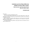
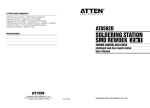
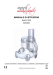
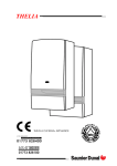
THELIA 30 E
IN WARRANTY
TECHNICAL HELPLINE
01773 828400
01773 828100
THIS IS A CAT II 2H3 APPLIANCE
1
INSTALLATION AND OPERATING INSTRUCTIONS
THELIA 30 E
Note!
The boiler serial number is marked on the label attached to the top of the inner bulkhead. Refer to
the 'Introduction' section page 3 for a description of the basic functions of the boiler. The 'Users'
section describes how to safely operate the boiler.
USERS SECTION
Introduction .................................................... Page 3
Commissioning ......................................................... 3
Controls & lighting .................................................... 4
Draining ..................................................................... 4
Servicing/maintenance .......................................... 4
INSTALLATION SECTION
Introduction .................................................. Page 3
Dimensions ............................................................. 5
Boiler schematic .................................................... 5
Technical data ...................................................... 6
Boiler connections ................................................. 7
Piping system installation ...................................... 7
Boiler location ........................................................ 8
Heating system design ......................................... 9
Domestic hot water system design ..................... 9
Boiler installation .................................................... 9
Flue installation ............................................. 10 - 11
Electrical installation ........................................... 12
Commissioning ............................................. 13 - 14
Operating safety devices .................................. 14
Settings .................................................................. 15
Changing gas type ............................................. 15
Mandatory warning for CEE countries
Warning: This appliance was designed, approved and inspected to meet the requirements of the English
market. The identification plate located on the inside of the appliance certifies the origin where the product
was manufactured and the country for which it is intended.
If you see any exception to this rule, please contact your nearest Saunier Duval dealer.
Thank you in advance for your assistance.
2
INTRODUCTION
The THELIA 30 E boiler is a wall mounted combination boiler providing central heating and instantaneous hot water.
The boiler is of the II 2H3 category for use with Natural Gas (G20) as distributed in the United Kingdom,
or Butane (G30), Propane (G31) or Towns gas
(G130).
Boilers burning LPG or similar gases MUST NOT be
fitted in basements or below ground level.
Domestic hot water demand always has priority
over heating demand.
The boiler is designed for use as part of a sealed
water central heating system with fully pumped circulation. The pump, expansion vessel and associated safety devices are all fitted within the boiler.
The boiler can be installed against either an external wall or on an adjacent inside wall, that is, the
flue system will pass directly to the rear or to either
side to the terminal fitted on the outside wall face.
The boiler has a fan assisted balanced flue which
both discharges the products of combustion to and
draws the combustion air from the outside of the
room.
The boiler is suitable for top outlet flue connection
only but, can be fitted with horizontal flue, vertical
flue or twin-pipe flue. Refer to flue catalogue for
further details.
The installation must be carried out by a competent person in accordance with the relevant requirements of The Building Regulations, The Water
Byelaws, The Building Standards (Scotland) Regulations and any applicable local regulations.
Both the central heating and domestic hot water
temperature are user adjustable from the boiler
control panel.
Ancillary equipment
A range of flue accessories are available including vertical flues, twin-pipe flues, bends etc.
For further information contact your supplier.
These instructions should be carefully followed for
the safe and economical use of your boiler.
COMMISSIONING
Gas safety (Installation and Use) Regulations
In your interests and that of gas safety, it is the law
that ALL gas appliances are installed and serviced
by a competent person in accordance with the
above regulations.
Boiler controls
The control panel, located at the lower front of the
boiler casing, see diagram 1, allows the boiler to
be started, shut down, controlled and monitored
during use.
Gas leak or fault
If a gas leak or fault exists or is suspected, turn the
boiler off and consult the local gas supply company or your installation/service company.
Flue
Do not obstruct the outside terminal of the boiler.
A
B
C
D
E
F
A
B
-
Pressure gauge
Temperature gauge
Reset button
N/A on this model
Mains 'ON' warning light
Loss of water warning light
C
D
E
G
H
I
J
K
L
F
G
H
-
N/A on this model
Safety shutdown warning light
Domestic hot water temperature control
Heating temperature control
'Summer/winter' selector
N/A on this model
I
J
K
L
bar
0
Hab 031a
Diagram 1
3
CONTROLS AND LIGHTING
Starting the boiler
Before starting the boiler check that:
• The gas meter tap is open.
• The boiler gas service cock is open.
• The boiler is connected to the electrical supply
and turned on.
Setting to SUMMER mode (Hot water only)
• Turn the OFF/Summer/Winter' switch (K) to the
'Summer'
position, see diagram 1.
• Turn the domestic hot water temperature control (I) to the desired setting, see diagram 1.
To obtain domestic hot water, open a hot water
tap.
Hot water always has priority over central heating.
Setting to WINTER mode (Heating and hot water)
• Turn the OFF/Summer/Winter selector switch to
(K) to the 'Winter'
position, see diagram 1.
• Turn the central heating temperature control (J)
to the desired setting, see diagram 1.
• Turn the domestic hot water temperature control (I) to the desired setting, see diagram 1.
• Make sure that any external controls are calling
for heat.
The heating system will begin to heat up.
To obtain domestic hot water, open a hot water
tap.
Hot water always has priority over central heating.
DRAINING
Protection against freezing
If the boiler is to be out of use for any long periods
during severe weather conditions, it is recommended that the whole system, including the boiler,
be drained to avoid the risk of freezing.
If in doubt, consult your servicing company.
The THELIA 30 E boiler has a built in frost protection
device that protects the boiler from freezing. If the
boiler is to be left and there is a risk of frost, ensure
that the gas and electrical supplies are left connected and that the OFF/Summer/Winter switch is
left in the'Summer' or 'Winter' position.The frost protection device will light the boiler when the temperature of the boiler water falls below 6°C. When
the temperature reaches 16°C, the boiler stops.
Note: This device works irrespective of any room
thermostat setting and only protects the boiler. Always ensure that adequate frost protection is given
to the entire system where necessary.
Draining and filling
Caution: The boiler is installed as part of a sealed
system which must only be drained and filled by a
competent person.
Heating safety valve
CAUTION: A safety valve with a discharge pipe is
fitted to this boiler.
The valve MUST NOT BE TOUCHED except by a competent person. If the valve discharges at any time,
switch the boiler off and isolate it from the electrical supply. Contact your installation/service company.
SERVICING/MAINTENANCE
To ensure the continued efficient and safe operation of the boiler, it is recommended that it is
checked and serviced at regular intervals. The frequency of servicing will depend upon the installation conditions and usage but, in general, once a
year should be enough.
Cleaning
The boiler casing can be cleaned with a damp
cloth followed by a dry cloth to polish.
Do not use abrasive or solvent cleaners.
4
Boiler casing
CAUTION. Do not remove or adjust the casing in
any way, as incorrect fitting may result in faulty operation. If in
DIMENSIONS
Diagram 2
260
80
217
Ø 100
The boiler is delivered in three separate packages:
- The boiler itself
- The fixing jig
- The flue system
For flue systems greater than 1 m long,
remove the cup restrictor from the
boiler flue outlet.
889
between 0,5 and 1,5 m
fit diaphragm (a)
seal
a - diaphragm
Net weight :
Gross weight :
Hab 036
520
393
55 kg
57 kg
BOILER SCHEMATIC
Diagram 3
15
A
B
C
D
E
-
-
Bypass
Loss of water pressure switch
Pump
Automatic air vent
Expansion vessel
Injector manifold
Ignition electrode
Expansion vessel filling valve
Overheat thermostat
Heat exchanger
Fan
Air pressure switch
Automatic air vent
Flame sense electrode
Thermostatic valve
3-way valve
Gas valve
Water valve
Safety valve (3 bar)
Domestic hot water expansion
vessel
Heating return
Cold water inlet
Heating flow
Domestic hot water flow
Gas supply
14
16
13
12
11
17
18
10
9
8
20
19
21
7
6
5
4
3
2
22
23
24
25
1
Shy 025
1
2
3
4
5
6
7
8
9
10
11
12
13
14
15
16
17
18
19
20
5
TECHNICAL DATA
Heating output
adjustable from 12,7 kW to 30,2 kW
Hot water outputauto. variable from 12,7 kW to 30,2 kW
43330 Btu/H to 103,040 Btu/H
Efficiency
81 %
90 °C
Maximum heating temperature
Expansion vessel effective capacity
10 l
Expansion vessel charge pressure
1,0 bar
Maximum system capacity at 75°C
190 l
Safety valve, maximum service pressure
43330 Btu/H to 103,040 Btu/H
65 °C
Maximum hot water temperature
Specific flow rate (for 30°C temperature rise) 14,5 l/min
Maximum supply pressure
7 bar
Maximum domestic hot water flow
12 l/min
Expansion vessel effective capacity
0,5 l
3 bar
Products outlet
60 mm
Fresh air inlet
100 mm
Electrical supply
230 V
Maximum absorbed power
165 W
Natural Nas
Butane
Propane
(G20)
G(30)
G(31)
Burner injector
1,2 mm
0,75 mm
0,75 mm
Inlet pressure
20 mbar
28 mbar
37 mbar
2,6 - 12,0 mbar
5,4 - 25,5 mbar
7,2 - 34,6 mbar
Gas rate (maximum)
3,54 m3/h
2,64 kg/h
2,6 kg/h
Gas rate (minimum)
1,56 m3/h
1,16 kg/h
1,15 kg/h
Burner pressure
By-pass open
50
40
30
20
By-pass closed
10
Pom 011
Available pressure (kPa) between
heating supply and return lines
Pump : Diagram 4
500
0
pressure
(mbar)
(10 kPa = 1 m WG)
1000
1500
Flow rate through heating system (I/h)
Burner setting pressures
Propane (G 31)
35,0
Butane (G30)
30,0
Natural gas (G 20)
25,0
20,0
15,0
5,0
Heat output (kW)
6
30,2
28
26
24
22
20
18
16
14
0,0
12,7
Burner
10,0
BOILER CONNECTIONS
From left to right the fixing jig comprises :
A - Heating return with isolating valve (m).
B - Cold water inlet with isolating valve (p).
C - Heating flow with isolating valve (q), drain
screw (r) and safety valve (s).
D - Domestic hot water outlet.
E - Electrical connection box.
F - Gas supply.
Diagram 5
5
5
Filters and washers:
1 - Fibre washer
2 - Metal filter
3 - Plastic filter
4, 5 and 6 -Black graphite
23
3
5
5
11
,5
7
5
34
25
2
,5
7
5
33
m
1
p
3
A
r
4
B
q
s
5
C
6
D
Pla 041
F
E
PIPING SYSTEM INSTALLATION
•
•
•
•
Heating system connections - Pipe diam 22 mm
Hot water system connections - Pipe diam 15 mm
Gas connection - Pipe diam 22 mm
Safety valve discharge - Pipe diam 15 mm
Water connection
Connect the copper tails and isolating cocks supplied, to the boiler, see diagram 5. Connect the
system pipework to the boiler observing the correct flow and return format as shown in diagram 5.
Safety valve discharge
WARNING. It must not discharge above an entrance or window or any type of public access
area.
Connect the safety valve discharge pipe to the
boiler, the discharge must be extended using not
less than 15 m o.d. pipe, to discharge in a visible
position outside the building, facing downward
preferably over a drain. The pipe must have a continuous fall and be routed to a position so that any
discharge of water, possibly boiling or steam, cannot create any danger to persons, damage to
property or external electrical components and
wiring. Tighten all pipe connection joints.
Gas connection
• The supply from the governed gas meter must
be of adequate size to provide a constant inlet
working pressure of 20 mbar (8 in w.g.).
To avoid low gas pressure problems, it is recommended that the gas supply is connected using 22
mm pipe.
• On completion, the gas installation must be
tested using the pressure drop method and purged
in accordance with the current issue of BS6891.
Gas Safety (Installation and Use) Regulations
In your interests and that of gas safety, it is the law
that ALL gas appliances are installed and serviced
by a competent person in accordance with the
above regulations.
7
BOILER LOCATION
Clearances
The position of the boiler must be such that there is
adequate space for servicing.
The recommended clearances are:
40 mm either side of the boiler.
600 mm at the front of the boiler.
300 mm below the boiler.
300 mm above the boiler.
Diagram 7
59
Ins 005a
Terminal position
The minimum acceptable spacings from the terminal to obstructions and ventilation openings are
shown in diagram 8.
The boiler must be installed so that the terminal is
exposed to the external air.
Should any doubt exist as to the permissible position of the terminal, contact the Saunier Duval
Technical Helpline 01773 828400.
• Mark the position of the holes for the hook and
connecting plate.
• Drill, plug and fix the connecting plate and hook
to the wall using suitable screws.
• Check that both the hook and connecting plate
are level.
-
889
63
If the boiler is not installed immediately, protect the
various couplings to prevent any ingress of foreign
materials e.g. plaster, paint etc.
• Place template on wall in required position, making allowances for the necessary clearances etc.
Note: It is permissible to install the boiler with reduced clearances at the bottom and sides of the
boiler PROVIDING that adequate consideration is
given for Servicing/Repairs at a later date. If any
doubt exists, contact the Saunier Duval Technical
Helpline 01773 828400.
A
B
C
D
E
F
G
135
767
135
Fixing jig
The fixing jig comprises three parts:
1) The connecting plate which allows the connection and soundness testing of all the pipework before the boiler is fitted and helps support the weight
of the boiler.
2) The hook which supports the weight of the boiler.
3) The template which ensures the hook and connecting plate are correctly fitted relative to one
another.
Diagram 8
520
Cupboard or compartment ventilation
The boiler can be fitted in a cupboard or compartment as long as adequate permanent high and
low level ventilation is provided in accordance with
ventilation requirements
Minimum dimensions (in mm) for the positioning of flue terminals
under a window ............................................ 300
under an air vent .......................................... 300
under a gutter ................................................. 75
under a balcony ........................................... 300
from an adjacent window ........................... 300
from an adjacent air vent ........................... 300
from vertical or horizontal air pipes ............... 300
H
I
L
M
N
-
from an external corner of the building ..... 300
from an internal corner of the building ...... 300
from the ground or from another floor ........... 300
between two terminals vertically ............ 1500
between two terminals horizontally ........... 600
G
N
C
E
F
M
A
D
I
L
H
Ven 060a
B
8
HEATING SYSTEM DESIGN
• Where thermostatic radiator valves are fitted, not
all radiators must be fitted with this type of valve,
and in particular, where the room thermostat is
installed.
• In the case of an existing installation, it is ESSENTIAL
that the system is thoroughly flushed prior to installing
the new boiler.
Filling the system
Provision must be made for filling the system at low
level. The use of a WRC approved filling loop is
strongly recommended, connected as shown in
diagram 6.
Diagram 6
Domestic
water
Boiler
Hot
Additional
expansion
vessel
(if required)
Tundish
(supplied)
Cold supply
Pressure
reducing
valve
(supplied)
Minimum 22 mm diameter
Return
Bypass
valve
Filling point
Heating
circuit
Flow
control valve
Sch 173
• The THELIA 30 E boiler is compatible with any type
of installation.
• Heating surfaces may consist of radiators, convectors or fan assisted convectors.
• Pipe sectional areas shall be determined in accordance with normal practices, using the output/
pressure curve (diagram 4). The distribution system
shall be calculated in accordance with the output requirements of the actual system, not the maximum output of the boiler. However, provision shall
be made to ensure sufficient flow so that the temperature difference between the flow and return
pipes be less than or equal to 20°C. The minimum
flow is 500 l/h.
• The piping system shall be routed so as to avoid
any air pockets and facilitate permanent venting
of the installation. Bleed fittings shall be provided
at every high point of the system and on all radiators.
• The total volume of water permitted for the heating system depends, amongst other things, on the
static head in the cold condition. The expansion
vessel on the boiler is pressurised at 1 bar (corresponding to a static head of 5 m w.g.) and allows
a maximum system volume of 150 litres for an average temperature of 75°C and a maximum service
pressure of 3 bar. This pressure setting can be modified at commissioning stage if the static head differs. An additional expansion vessel can be fitted
to the system if required, see diagram 6.
• Provision shall be made for a drain valve at the
lowest point of the system.
Drain point
DOMESTIC HOT WATER SYSTEM DESIGN
• Copper tubing must be used for the domestic
hot water system. Unnecessary pressure losses
should be avoided.
• The flow restrictor must be fitted in the cold water inlet during installation. This limits the flow through
the boiler to a maximum of 12 l/min.
BOILER INSTALLATION
Statutory requirements
The installation of this boiler must be carried out by
a competent person in accordance with the relevant requirements of the current issue of:
The Gas Safety (Installation and Use) Regulations
The Building Regulations
The local water company Byelaws
The Building Standards Regulations (Scotland)
The Health and Safety at Work Act
Sheet metal parts
WARNING. When installing or servicing this boiler,
care should be taken when handling the edges of
sheet metal parts to avoid the possibility of personal
injury.
Installing the boiler
Prior to starting work, the system must be thoroughly
flushed so as to eliminate any foreign bodies and
contaminants such as filings, solder particles, oil,
grease etc.
Note. Solvent products could cause damage to the
system.
• Engage boiler upper part onto the hanging
bracket.
• Allow the boiler to seat down onto support plate.
• Fit filter and washers, strictly adhering to the sequential order and directions shown on diagram 5.
• Connect the various couplings between boiler
and connection plate.
9
FLUE INSTALLATION
The boiler is only suitable for top outlet flue connection.
A - Flue to rear of boiler
• Mark correct position of hole from template.
Diagram 9
∆L2
∆L1
B - Flue to side of boiler
• Mark the horizontal centre line for the hole on
the rear wall. Extend the horizontal centre line to
the side wall and mark the vertical centre line of
flue hole as shown in diagram 9.
∆L2
∆L1
Under normal circumstances, it will be possible to
gain access to the outside of the building to fit the
flue terminal assembly. Where outside access is not
possible e.g. high rise buildings, the flue terminal
can be fitted from inside the building only if required.
Cutting the flue hole
• Making allowance for the slope of the flue, cut
hole in external wall, preferably using a core drill.
For installations with internal and external access Use a 105 mm diameter core drill.
For installations with internal access only - Use a
125 mm diameter core drill.
Important: Before cutting the hole for flues to the
rear of boiler, always cover fixing jig to make sure it
is not damaged.
Calculation of flue cutting lengths
• Measure wall thickness e (mm), see diagram 9.
• For side flues, measure distance from inside face
of side wall to centre line of flue and subtract 260
mm for right and left hand flue to get dimension a
(mm).
• Refer to table 1 for cutting lengths of both inner
and outer flue pipes for each of the various flue
options available.
Important: All flue cutting lengths must be measured from the terminal end of the flue pipes, see
diagram 10.
When the dimension X measured on site is greater
than that given in table 1, a flue extension kit will
be required, refer to table 2 for details.
e
a
e
a
X
X
Diagram 10
Outer pipe
Cutting length
Terminal end
Inner pipe
Cutting length
Ven 089
Important: When cutting the flue hole and when
extending the flue centre line to a side wall, remember that the flue system must have a fall of about
35 mm per metre of flue DOWNWARD AWAY FROM
the boiler. There must NEVER be a downward incline towards the boiler.
Table 1
Flue option
Rear flue
Cutting length (mm)
outer pipe inner pipe
e + 145
e + 228
Comments
maximum wall
thickness "e" without
extension 522 mm
Side flue left e + a + 188 e + a + 271
maximum
distance "X" without
extension 739 mm
Side flue right e + a + 188 e + a + 271
maximum
distance "X" without
extension 739 mm
Table 2
10
Flue option
Dimension "X"
N° of
extension kits
Side flue
left or right
522 to 1478 mm
1479 to 2479 mm
1
2
FLUE INSTALLATION
Extended flue
The horizontal flue is extended by using one or more
of the 1000 mm extension pipes, Saunier Duval part
number 85091. These are connected together by
push fit type joints, clamps and seals.
Table 3
Flue option
Calculation of flue cutting lengths for extended flue
• Using the correct number of extension kits as table 2, measure dimensions a and e, see diagram
9. Cut both the inner and outer pipe to the dimensions given in table 3.
Comments
Side flue left e + a - 1479 e + a - 1479
maximum
dimension "X" without
extension 739 mm
Side flue right e + a - 1479 e + a - 1479
maximum
dimension "X" without
extension 739 mm
Diagram 11
Important: All cutting lengths should be measured
from the push fit end of the extension pipe. Do not
leave any burrs or sharp edges on the cut ends of
the pipes.
P O Q N R
U
T
S
V
Pho 088
Installation of flue assembly
• Fit rubber sealing collar (P) into groove at the
outer end of pipe (N), see diagram 11.
• Fit outer pipe (N) into wall with groove to the
outside.
• Pull pipe inwards to bring rubber sealing collar
hard up against external wall, see diagram12.
• Fit internal plastic flange (Q) onto outer pipe.
Push along the pipe until engaged against internal wall.
• From inside, insert inner pipe (O) into outer pipe.
• Fit both 'O' rings (T) into the flue elbow (V), one
at the inlet, one at the outlet. By necessity, they
are a loose fit, apply a small amount of silicone
grease to each 'O' ring when fitting.
• Slacken the two screws and fit the clamp and
seal (R) onto the elbow.
• Take hold of the inner flue and push gently onto
the elbow outlet taking care not to tear the 'O' ring.
Diagram 12
Pho 087
Important: If the flue has been cut, ensure that there
are no burrs that could damage the 'O' ring.
• Push the elbow clamp and seal over the outer
flue.
• For flue systems less than 1 m long, leave the cup
restrictor (a) fitted in the boiler flue outlet, see diagram 13.
Cutting length (mm)
outer pipe inner pipe
• Remove the backing from the self adhesive gasket (S) and carefully fit gasket to base of flue elbow.
• Fit spacer (b) onto underside of elbow, fit elbow
onto boiler and secure with the four screws (U).
Diagram 13
L
Spacer b
5
Hab 243
16
18
2
80
Restrictor a
11
ELECTRICAL INSTALLATION
WARNING. This boiler must be earthed.
All system components shall be of an approved type.
Do not interrupt the supply with a time switch or programmer.
Connection of the whole electrical system and any
heating system controls to the electrical supply must
be through a common isolator.
WARNING. ON NO ACCOUNT MUST ANY EXTERNAL
VOLTAGE BE APPLIED TO ANY OF THE TERMINALS ON
THE HEATING CONTROLS CONNECTION PLUG.
Isolation should preferably be by a double pole switched fused spur box having a minimum contact
separation of 3 mm on each pole. The fused spur box
should be readily accessible and preferably adjacent to the boiler. It should be identified as to its use.
Warning : This appliance must be wired in accordance with these instructions. Any fault arising from incorrect wiring cannot be put right under the terms of
the Saunier Duval guarantee.
Connect the integral supply lead, coiled and tucked
behind the boiler, to the mains supply.
Important : The integral mains supply lead is specific to
the boiler. A replacement can be obtained by quoting part number 57037.
A fused three pin plug and socked outlet may be
used instead of the fused spur box provided that,
a) They are not used in a room contaning a fixed bath
or shower
b) Both the plug and socket comply with the current
issue of BS 1363.
The mains electrical supply must be maintained at all
times in order to provide correct operation of the
boiler.
External controls
The boiler will work for heating without a room thermostat and/or timeswitch being connected provided that the wire link fitted between the top two terminals of the connector is left in place, see diagram
14.
A 230V room thermostat can be used but do not
make any connection to the compensating resistor,
see diagram 14.
ON NO ACCOUNT must any electrical voltage be
applied to any of the terminals of the external controls plug.
For use with a timeswitch or timeswitch and room
thermostat see diagram 14.
All models
In case of difficulty obtaining a suitable timeclock/
room thermostat, a programmable room thermostat
is available as an accessory, Saunier Duval part
number 40010. Please contact your supplier.
No external controls
Factory
fitted link
Boiler
connector
Room thermostat only
Voltage free room
thermostat
External controls
plug
Do not
connect
Room thermostat and time clock
Time clock
Diagram 14
12
External
controls plug
Voltage free room
thermostat
Do not
connect
EXTERNAL CONTROLS CONNECTIONS
Warning:
- All external controls must be voltage free
- On no account must any external voltage
be applied to any of the external controls
plug terminals
COMMISSIONING
The commissioning and first firing of the boiler must
only be done by a competent person.
Diagram 15
Gas installation
It is recommended that any air is purged from the
supply at the gas inlet test point on the lower right
hand side of the gas valve, see diagram 15.
Filling the system
• Open shut off valves, see diagram 5 (slot of screw
corresponds to flow direction), and caps on automatic air vents on top of pump and top right hand
side of boiler.
• Bleed each radiator until a continuos jet of water is obtained.
• Do not close automatic air vent caps on boiler.
• Open various hot water taps to bleed system.
• Make sure that pressure gauge reads between
1 and 2 bar. Re-pressurise system as necessary.
Gas inlet
test point
First starting up
• Following the instructions given in the 'Controls
and Lighting' section, set boiler to run in central
heating mode.
• Set boiler thermostat for maximum temperature
and check that any external controls, if fitted, are
calling for heat.
• Allow the temperature to rise to the maximum
value, with all radiator valves open.
The temperature rise will cause release of the gases
contained in the water of central heating system.
- Gases driven towards the boiler will be automatically released through the automatic air vents.
- The gases trapped at the highest point of the system must be released by bleeding the radiators.
On reaching maximum temperature, the boiler
should be turned off and the system drained as
rapidly as possible whilst still hot.
• Refill system to a pressure of 1 bar and vent as
before.
• Restart boiler and operate until a maximum temperature is reached. Shut down boiler and vent
heating system. If necessary, top up heating system and make sure that a pressure of 1 bar is indicated on the pressure gauge when system is COLD.
Gas pressures
The main burner pressure should be checked during commissioning to make sure the correct input
is obtained. Proceed as follows:
• Shut down boiler.
Diagram 16
Connect the pressure gauge to MP and
RMP
MP = measuring point
RMP = reference measuring point
pressure gauge
Ins 006
Starting the boiler
Before starting the boiler check that:
- The gas meter tap is open.
- The boiler gas service cock is open.
- The boiler is connected to the electrical supply.
Ins 009
Important:
- If this procedure is not carried out properly, the
boiler will go into safety lock-out until all of the air
has been purged.
- When venting air from boiler, do not touch the
schrader valve on the expansion vessel, it is NOT a
vent.
• Undo screws on burner pressure test points RMP
and MP below sealed combustion chamber, see
diagram 16.
• Connect a suitable pressure gauge.
• Gain access to the rear of the control panel and
locate the range rating adjuster screw, see diagram 17.
• Start boiler as described in 'Instruction for Use'.
• Set OFF/Summer/Winter switch to 'Winter' (Heating and hot water ) position.
13
COMMISSIONING
Note: This adjustment does not affect the domestic hot water output.
If measured burner pressure differs greatly from the
given figure, check the gas inlet pressure as follows:
• Shut down boiler.
• Remove screw from inlet test point on the side of
the gas valve, see diagram 15.
• Connect a suitable pressure gauge.
• Start boiler as described in 'Instructions for Use'.
• Check that the inlet pressure reading matches
that given in 'Technical Data' for the type of gas
being used.
Diagram 17
Reg 014
• Set boiler thermostat to maximum and check
that any external controls are calling for heat.
• Check that the reading on the gauge matches
that given in 'Technical Data' for the type of gas
being used.
• Adjust the range rating adjuster screw as necessary to obtain the desired input.
• Shut down boiler.
• Remove pressure gauge, tighten up test point
screws and check for gas soundness.
• Using a ball point pen, clearly indicate on the
data label the input the boiler is set to.
• Shut down boiler.
• Remove pressure gauge, tighten up test point
screws and check for gas soundness.
• If the gas pressure is incorrect, refer to the Fault
Finding section in 'Servicing Instructions'.
• If the inlet pressure is below that given, the gas
supply pipework/meter must be checked and any
fault corrected.
• In the case of an LPG installation, check the storage tank or cylinder, regulator and pipework.
OPERATING SAFETY DEVICES
Gas leak or fault
If a gas leak or fault exists or is suspected, turn the
boiler off and consult the local gas undertaking or
your installation/servicing company.
In case of power supply failure
The boiler no longer operates.
As soon as power supply is restored, the boiler will
be automatically restarted.
Air flow rate safety device
If an obstruction, even partial, of the flue occurs,
for any reason whatsoever, the built in safety system of the boiler will turn the boiler OFF and the
fan will continue to run.
The boiler will be ready to operate when the fault
has been cleared.
In case of loss of water in the system
CAUTION. The boiler is installed as part of a sealed
system which must only be
drained and filled by a competent person.
If the pressure shown on the
pressure gauge is less than 1
bar or if the red loss of water
warning light is ON, the system
must be filled up immediately. Call your Installation/
Servicing company.
14
Important notice: A central heating system cannot
operate satisfactorily unless it is properly filled with
water and unless the air initially contained in the
piping systems has been properly bled off. If these
conditions are not satisfied, air noise will occur
within the system.
Air in the heating system
Persistent air in the heating system may indicate
leaks in the system or corrosion taking place. Call
your Installation/Servicing company.
Overheat safety
In the event of a problem, the overheat safety
devices cause safety shutdown of the boiler. If this
happens, call your Installation/Servicing company.
The THELIA 30 E boiler has a built in frost protection
device that protects the boiler from freezing. If the
boiler is to be left and there is a risk of frost, ensure
that the gas and electrical supplies are left connected and that the OFF/Summer/Winter switch is
left in the'Summer' or 'Winter' position.The frost protection device will light the boiler when the temperature of the boiler water falls below 6°C. When
the temperature reaches 16°C, the boiler stops.
Note: This device works irrespective of any room
thermostat setting and only protects the boiler. Always ensure that adequate frost protection is given
to the entire system where necessary.
SETTINGS
Gas valve setting
All boilers are tested and factory set during manufacture. Should it be necessary to reset a gas valve,
for example after replacement, proceed as follows:
• Shut down boiler.
Diagram 18
Maximum setting
• Reconnect the electrical connector removed
from the modulating gas valve coil.
• Remove the protective cover from the gas valve
adjuster.
• Turn nut 'B' , see diagram 18:
CLOCKWISE: To increase the pressure.
ANTICLOCKWISE: To decrease the pressure.
Reg 020
Minimum setting
• Remove one electrical connector from the
modulating gas valve coil, see diagram 18.
• Connect a suitable pressure gauge as described
in 'Commissioning'.
• Turn the OFF/Summer/Winter switch to the 'Summer' position.
• Turn the domestic hot water temperature adjuster to maximum setting.
• Remove the protective cover from the gas valve
adjuster.
• Turn nut 'A' , see diagram 18:
CLOCKWISE: To increase the pressure.
ANTICLOCKWISE: To decrease the pressure.
Diagram
Diagram 19
19
After adjustment, refit the cover to the gas valve
adjuster.
➞
Reg 046
Bypass
The THELIA 30 E has a built-in bypass. This must be
adjusted according to the requirements of the system, refer to the flow rate pressure curve (diagram
4). The boiler is supplied with the built-in bypass
open a half a turn. It is adjusted by turning the bypass screw, see diagram 19. Turn the screw clockwise to close the bypass.
When using thermostatic radiator valves (TRV's), it
is recommended that an additional, adjustable
bypass of 15 mm minimum diameter is fitted between the flow and return of the heating circuit,
see diagram 6. Any bypass must be fitted before
system controls.
CHANGING GAS TYPE
Should it become necessary to change the gas type, a modification kit will be required.
This modification must only be carried out by a suitably qualified engineer.
Conversion: Natural Gas (G20) to G30/G31
Conversion: Natural Gas (G20) to G130
Part No.
Part No.
85402
85205
15