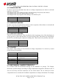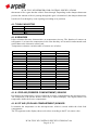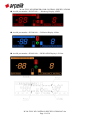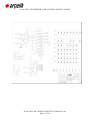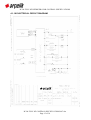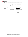
1
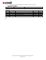
B-764 FULL NF REFRIGERATOR CONTROL SPECIFICATIONS B-764 FULL NF REFRIGERATOR CONTROL SPECIFICATIONS 1 B-764 FULL NF CONTROL SPECIFICATIONS 007.doc Page 1 of 30 B-764 FULL NF REFRIGERATOR CONTROL SPECIFICATIONS HISTORY SHEET Date of Issue Prepared by 29.11.2004 Ferkan GULBAS Approved by Emre ARISOY Revisions. Rev. # Revised page(s) 001 002 003 004 005 006 007 ALL ALL ALL ALL ALL ALL Revision and reason Date Approval New heater added / fan removed. Fan operation is removed, damper heater is added Defrost algorithm 06.12.2004 14.12.2004 24.02.2005 10.03.2005 30.03.2005 05.04.2005 13.06.2005 F.GULBAS F.GULBAS F.GULBAS F.GULBAS F.GULBAS F.GULBAS F.GULBAS 2 B-764 FULL NF CONTROL SPECIFICATIONS 007.doc Page 2 of 30 B-764 FULL NF REFRIGERATOR CONTROL SPECIFICATIONS TABLE OF CONTENTS 1 HISTORY SHEET..........................................................................................................................................................................2 2 TABLE OF CONTENTS ................................................................................................................................................................3 3 INTRODUCTION ...........................................................................................................................................................................5 4 COMPONENTS.............................................................................................................................................................................6 4.1 COMPONENT LIST ..............................................................................................................................................................6 4.1.1 COMPRESSOR............................................................................................................................................................6 4.1.2 DRAIN HEATER ...........................................................................................................................................................7 4.1.3 DEFROST HEATER .....................................................................................................................................................7 4.1.4 AIR DUCT HEATER .....................................................................................................................................................7 4.1.5 IONIZER .......................................................................................................................................................................7 4.1.6 MECHANICAL DAMPER TERMOSTAT ......................................................................................................................7 4.1.7 RUN CAPACITOR ........................................................................................................................................................8 4.1.8 SENSORS ....................................................................................................................................................................8 4.1.8.1 FRZ AIR (FREEZER COMPARTMENT) SENSOR...............................................................................8 4.1.8.2 FF AIR (COOLING COMPARTMENT) SENSOR .................................................................................8 4.1.8.3 FRZ EVAPORATOR (DEFROST) SENSOR ........................................................................................9 4.1.9 PTC RELAY..................................................................................................................................................................9 4.1.10 THERMIC ...................................................................................................................................................................9 4.1.11 DOOR BUTTON .........................................................................................................................................................9 4.1.12 ILLUMINATION LAMB AND SOCKETS ...................................................................................................................10 4.1.12.1 ILLUMINATION LAMB ........................................................................................................................10 4.1.12.2 LAMB HOLDER ..................................................................................................................................10 4.1.13 ELECTORNIC CONTROL BOARD ..........................................................................................................................10 4.1.13.1 PLACE FOR THE BOARD ..................................................................................................................11 4.1.14 DISPLAY BOARD.....................................................................................................................................................11 PLACE FOR THE BOARD ..................................................................................................................................................13 PLACE FOR THE BOARD ..................................................................................................................................................14 4.1.15 CONNECTORS ........................................................................................................................................................14 4.1.16 ELECTRICAL CIRCUIT DIAGRAM ..........................................................................................................................15 5 ALGORITHM ...............................................................................................................................................................................17 5.1 COOLING ALGORITHM .....................................................................................................................................................17 5.2 HOT START-UP..................................................................................................................................................................17 5.2.1 PARAMETER LIST.....................................................................................................................................................17 5.2.2 ELECTRICITY SHORTAGE .......................................................................................................................................17 5.3 How to calculate CDC? .......................................................................................................................................................17 5.4 FF TEMPERATURE SETTINGS ........................................................................................................................................18 5.5 FRZ TEMPERATURE SETTINGS ......................................................................................................................................18 5.5.1 PARAMETER LIST.....................................................................................................................................................18 5.5.2 ELECTRICITY SHORTAGE .......................................................................................................................................18 5.6 ACTUAL FF TEMPERATURE DISPLAY ............................................................................................................................18 5.6.1 PARAMETER LIST.....................................................................................................................................................19 5.7 ACTUAL FRZ TEMPERATURE DISPLAY .........................................................................................................................19 5.7.1 PARAMETER LIST.....................................................................................................................................................20 5.8 DEFROST CYCLE ..............................................................................................................................................................20 5.8.1 PARAMETER LIST.....................................................................................................................................................21 5.9 CRITICS OF DEFROST CYCLES ......................................................................................................................................21 5.10 ELECTRICITY SHORTAGE .............................................................................................................................................21 5.11 DEFROST IN QUICKFREEZE..........................................................................................................................................21 5.11.1 PARAMETER LIST...................................................................................................................................................22 6 FUNCTIONS................................................................................................................................................................................22 6.1 QUICK FREEZE..................................................................................................................................................................22 6.1.1 PARAMETER LIST.....................................................................................................................................................22 6.1.2 ELECTRICITY SHORTAGE .......................................................................................................................................22 6.2 ECONOMY..........................................................................................................................................................................23 6.2.1 PARAMETER LIST.....................................................................................................................................................23 6.3 ECO-FUZZY........................................................................................................................................................................23 6.3.1 PARAMETER LIST.....................................................................................................................................................23 6.3.2 ELECTRICITY SHORTAGE .......................................................................................................................................23 6.4 FOCUS-COOL ....................................................................................................................................................................23 6.4.1 PARAMETER LIST.....................................................................................................................................................24 6.4.2 ELECTRICITY SHORTAGE .......................................................................................................................................24 6.5 DOOR OPEN ALARM.........................................................................................................................................................24 6.5.1 PARAMETER LIST.....................................................................................................................................................24 6.5.2 ELECTRICITY SHORTAGE .......................................................................................................................................24 6.6 IONIZER..............................................................................................................................................................................25 6.6.1 PARAMETER LIST.....................................................................................................................................................25 6.7 HIGH TEMPERATURE ALARM..........................................................................................................................................25 6.7.1 PARAMETER LIST.....................................................................................................................................................25 6.7.2 ELECTRICITY SHORTAGE .......................................................................................................................................25 7 SELF TEST .................................................................................................................................................................................25 7.1 PRODUCTION TEST..........................................................................................................................................................26 7.2 SERVICE TEST ..................................................................................................................................................................26 7.3 RUNNING TEST .................................................................................................................................................................27 B-764 FULL NF CONTROL SPECIFICATIONS 007.doc Page 3 of 30 B-764 FULL NF REFRIGERATOR CONTROL SPECIFICATIONS 7.3.1 ELECTRICITY SHORTAGE .......................................................................................................................................28 7.4 DEFAULT OPERATING MODE..........................................................................................................................................28 7.4.1 PARAMETER LIST.....................................................................................................................................................28 8 SAFETY AND STANDARDS.......................................................................................................................................................29 8.1 STANDARDS ......................................................................................................................................................................29 8.2 SPECIAL TESTS ................................................................................................................................................................29 3 B-764 FULL NF CONTROL SPECIFICATIONS 007.doc Page 4 of 30 B-764 FULL NF REFRIGERATOR CONTROL SPECIFICATIONS INTRODUCTION B-764 is a semi electronic full no-frost refrigerator, which is called as combi with two compartments that are freezer and fresh-food cooling compartments. A compressor and a fan control the cooling of these two compartments. The fan is connected parallel to the compressor. Refrigerator functions and temperature settings of the freezer are to be adjusted under control of user due to the microprocessor. For temperature adjustment of fresh-food customer has to use thermostat knob. 4 B-764 FULL NF CONTROL SPECIFICATIONS 007.doc Page 5 of 30 B-764 FULL NF REFRIGERATOR CONTROL SPECIFICATIONS COMPONENTS 4.1 COMPONENT LIST No 1 2 3 4 5 6 7 8 9 10 11 12 13 14 15 16 17 Name Compressor Freezer Fan Damper Heater Defrost Heater Duct Heater Ionizer (optional) Mechanical Damper Thermostat Run Capacitor Sensor Thermal Fuse PTC relay Thermic Door button Illumination light and socket Electronic Control Board Display Board Connection cable (Between Display-Control card) Quantity 1 1 1 1 2 1 1 1 3 1 1 1 2 1 1 1 2 Control by Board output Board output Board output Board output Board output Board input 6pins Board input 2pins Board output 6pins 4.1.1 COMPRESSOR The compressor provides cooling gas circulation and works by a “static cooling” system. Power supply is made via a protective thermic. At the first startup, it works by an auxiliary coil and later this coil is cut out by PTC. Manufacturer Production code Operating Voltage Power (W) Locked rotor current (LRA) Insulation Operation current Life expectancy ACC HTK95AA 187-242 9,17 0,46A 300.000 cycle minimum B-764 FULL NF CONTROL SPECIFICATIONS 007.doc Page 6 of 30 B-764 FULL NF REFRIGERATOR CONTROL SPECIFICATIONS 4.1.2 DRAIN HEATER In order to prevent accumulated frost and ice on fridge compartment, new heater is activated and the ice is removed. The damper heater starts running together with the opening of any doors after defrost. The damper heater runs only during compressor OFF. The damper heater stops together with starting of the defrost cycle. Manufacturer Power Isolation Resistance Korel 4 W ±%15 100 MegaOhm 4.1.3 DEFROST HEATER In order to prevent accumulated frost and ice on the evaporator, defrost heater is activated and the ice is removed from the evaporator surface. Manufacturer Resisrtance Power Isolation Resistance Korel 323 ohm 110 W ±%15 100 MegaOhm 4.1.4 AIR DUCT HEATER There are two air duct heaters. They are placed on the air passages. One of the duct heaters is for the pressure air duct and the other is for the suction air duct. The heaters are controlled by the MCU by considering the compressor running time. These heaters are paralelly connected. Manufacturer Resisrtance Power Isolation Resistance Korel 5 W ±%15 100 MegaOhm 4.1.5 IONIZER The ionizer cleans inside air from bacterias in fridge compartment. It is driven by control board with special algorithm. Manufacturer Production code Input voltage Power Consumption Output voltage Input current (min) Negative ion output Approved by Fu Fong FA1-7-0 (AC220V) AC220 ~ 240V/50-60Hz 0,8W (Maximum) 0,3W (Minimum) -5,9KV ~ -7,0KV (1GΩ) 1,3mA 2,000,000 ions/cc (minimum) at 30cm distance VDE 4.1.6 MECHANICAL DAMPER TERMOSTAT It is located inside the thermostat housing on the multiflow air passage. The Damper thermostat position changes according to fridge compartment temperature and theset value. It does not need any electrıcal connectıon for the control board. The air inside the freezer compartment moves towards the freshfood compartment via damper thermostat. The damper B-764 FULL NF CONTROL SPECIFICATIONS 007.doc Page 7 of 30 B-764 FULL NF REFRIGERATOR CONTROL SPECIFICATIONS thermostat is like a gate that the cold air flows through. Depending on the damper thermostat position the amount of the air passing through this gate is determined. (the damper thermostat lets the air flow through by some openings according to its position) 4.1.7 RUN CAPACITOR Manufacturer Production code Voltage Value Epcos/Ducati/Arcotronics 16.10.08 (ducati) 450 VAC 4µF 4.1.8 SENSORS It has resistance-decrease characteristics as temperature rises up. The function of sensors on refrigerators is to sense the temperature in the area that they are located in and transmit such sensed data to the electronic control card. Temperature-resistance variation table of sensors are as below: Temperature (°C) -40 -35 -30 -25 -20 -15 -10 -5 0 5 10 15 20 25 30 35 40 45 50 RT/R25 rate R deviation 33.25 24.01 17.53 12.93 9.636 7.249 5.503 4.214 3.251 2.532 1.986 1.568 1.248 1.000 0.8051 0.6528 0.5325 0.4368 0.3602 2.64 2.40 2.16 1.93 1.71 1.49 1.29 1.08 0.89 0.70 0.52 0.34 0.17 0.00 0.16 0.32 0.47 0.62 0.77 Resistance (kΩ) 332.50 240.10 175.30 129.30 96.36 72.49 55.03 42.14 32.51 25.32 19.86 15.68 12.48 10.00 8.051 6.528 5.325 4.368 3.602 4.1.8.1 FRZ AIR (FREEZER COMPARTMENT) SENSOR It transmits the temperature it senses within the freezing compartment to the microprocessor. The compressor, Fan and the heaters either run or stop accordingly. The display shows real temperature inside the freezer compartment. 4.1.8.2 FF AIR (COOLING COMPARTMENT) SENSOR It transmits the temperature to the microprocessor, which is sensed within the fresh food compartment. The FF segments on the display shows real values according to the FF air sensor value. B-764 FULL NF CONTROL SPECIFICATIONS 007.doc Page 8 of 30 B-764 FULL NF REFRIGERATOR CONTROL SPECIFICATIONS 4.1.8.3 FRZ EVAPORATOR (DEFROST) SENSOR It transmits the temperature sensed on the fresh-food evaporator to the microprocessor. The defrost mode either continues or ends accordingly. The compressor, fan and heaters either run or stop accordingly 4.1.9 PTC RELAY It has resistance-decrease characteristics as temperature rises up. It provides the first start up by putting the auxiliary coil of compressor into operation. Then it leaves auxiliary coil out of operation as it is heated up by means of the current passing over. 4.1.10 THERMIC It is a component that becomes an open circuit when it becomes heated. When the compressor does not operate, the thermic heats up as the auxiliary coil is heated and cuts the current fed to the compressor once a certain temperature is reached. Manufacturer Production code Reaction Time Minimum time between two successive LRA Electrica T0602 7,5-14sn. (4.5 A , 25°C) 211 sec. Under static cooling and Voltage=198 V 4.1.11 DOOR BUTTON It is an ON/OFF switch. Internal illumination lamp is on when the fresh-food door is opened. The internal illumination is provided through fresh-food door button. Supply voltage to fan is cut off when the freezer door is opened and 220VAC signal transmitted to the card. When the freezer door is closed, supply voltage to fan is provided again and 0V is transmitted to the card. The door buttons are used to sense both FF and FRZ (optional) doors individually. The electronic board has no control on the internal illumination. Manufacturer Production code Matsushita MM7 When any of the doors are opened Freezer Fan is stopped by the door button if operating B-764 FULL NF CONTROL SPECIFICATIONS 007.doc Page 9 of 30 B-764 FULL NF REFRIGERATOR CONTROL SPECIFICATIONS 4.1.12 ILLUMINATION LAMB AND SOCKETS 4.1.12.1 ILLUMINATION LAMB One piece of E14 type 15W/220VAC lamp is used in order to illuminate fresh-food compartment only. This lamp is fed by the supply cables when the door is opened. There is not connection between the control board and the illumination lamb. Manufacturer Production code Input voltage Power Consumption Output voltage Input current (min) Negative ion output Approved by Fu Fong FA1-7-0 (AC220V) AC220 ~ 240V/50-60Hz 0,8W (Maximum) 0,3W (Minimum) -5,9KV ~ -7,0KV (1GΩ) 1,3mA 2,000,000 ions/cc (minimum) at 30cm distance VDE 4.1.12.2 LAMB HOLDER It is used for accommodating the E14 type 15W/220VAC lamp. Manufacturer Production code Voltage BJB or Nova L200 250 V Max 4.1.13 ELECTORNIC CONTROL BOARD The characteristics of the card and the components thereon are indicated below: Card dimension: 140 x 51 x 1,6 mm tallest component 25mm on the pcb Buzzer will be placed on the control board, 4KHz 90dB Display connector: it is for connection with display board, Sensor connector: it is used for connection between sensors (FF, EVA and FRZ), Power connector: It is for connection of control elements. (Compressor, Drain Heater, Duct Heaters, Defrost Heater, Ionizer, phase and neutral, Door Switches (2)), Driver circuit elements: they are triacs to control cooling system elements (Compressor Duct Heaters, Defrost Heater, Drain Heater, Ionizer). Serial communication connector: (it is prepared for edge type connector on the edge of PCB), provides the transfer of parameters to computer when refrigerator is working and changing parameters by means of computer During the edge connector is in use, display functionality will be over. Board must get approval of VDE and BEAB. Arcelik part number: 4326110100 will be placed on the control board. The arcelik stock number will be placed on the board with a label. B-764 FULL NF CONTROL SPECIFICATIONS 007.doc Page 10 of 30 B-764 FULL NF REFRIGERATOR CONTROL SPECIFICATIONS 4.1.13.1 PLACE FOR THE BOARD It is located in upper back part of the refrigerator inside the thermostat housing. 4.1.14 DISPLAY BOARD Display board and its components are explained below: Board dimensions For Diffusion (101.5 X 29 X 10) and for Blomberg (100 X 25.5 X 10) and BEKO (4325970100) Chip on Board technology will be used One button for Quick Freeze (QFRZ) One button for FRZ set One button for Eco-Fuzzy One button for Focus-Cool Communication with control board: serial communication over 6 cables Two digits and “-“ sign 7-segment display: FRZ set / actual value display (Minimum -99) One and half digit and “-“ sign 7-segment display: FF actual value display (Minimum -19) Exclamation Icon: warns user for any possible fault on system components or “high temperature warning”. Economy Icon: indicates the energy efficient operating conditions QFRZ Icon: warns user when QFRZ function is active, Eco-Fuzzy Icon: warns user when Eco-Fuzzy function is active, Focus-Cool Icon: warns user when focus cool function is active, Freezer Bar Graphs: indicates the set temperature of the freezer compartment Ion Icon: always on and indicates that ionizer exists (valid for 4325970100 only) B-764 FULL NF CONTROL SPECIFICATIONS 007.doc Page 11 of 30 B-764 FULL NF REFRIGERATOR CONTROL SPECIFICATIONS Arcelik part number: 4325970100 ---- Blomberg Display is RED Arcelik part number: 4325980100---- Diffusion Display is Blue Arcelik part number: 4328830100---- BEKO OEM Display is Yellow B-764 FULL NF CONTROL SPECIFICATIONS 007.doc Page 12 of 30 B-764 FULL NF REFRIGERATOR CONTROL SPECIFICATIONS B-764 FULL NF CONTROL SPECIFICATIONS 007.doc Page 13 of 30 B-764 FULL NF REFRIGERATOR CONTROL SPECIFICATIONS PLACE FOR THE BOARD It is located on the front door. 4.1.15 CONNECTORS The connections between the display board, control board the sensors are made via the connectors. NR 1 CONNECTIONS IN BETWEEN on display card 2 on cable (to be attached to display card) (dispÆ contr) 3 4 5 6 7 On control card (disp. Socket) On cable (to be attached to control card) (contÆ disp) Sensor socket on control card Sensor socket on cable group power socket on control card 8 power socket on cable group COMPANY Molex PART NUMBER 22-03-5065 Molex 50-37-5063 22-03-5065 50-37-5063 22-23-3064 22-41-5062 10-63-1093 10-22-1082 B-764 FULL NF CONTROL SPECIFICATIONS 007.doc Page 14 of 30 B-764 FULL NF REFRIGERATOR CONTROL SPECIFICATIONS 4.1.16 ELECTRICAL CIRCUIT DIAGRAM B-764 FULL NF CONTROL SPECIFICATIONS 007.doc Page 15 of 30 B-764 FULL NF REFRIGERATOR CONTROL SPECIFICATIONS frzSwitchDoor OPEN/CLOSE ffSwitchDoor OPEN/CLOSE frzTempAir Duct Heater 2x5W ffTempAir REFRIGERATOR CONTROL ffTempEva COMP (LRA10,5A) with thermal protection 14sec ON / 211 sec OFF HEATER 200W IONIZER DAMPER FAN HEATER frzTempSet B-764 FULL NF CONTROL SPECIFICATIONS 007.doc Page 16 of 30 B-764 FULL NF REFRIGERATOR CONTROL SPECIFICATIONS 5 ALGORITHM Defines refrigerator-working logic. It constitutes a base for software prepared for refrigerator. It defines all electrical functions of refrigerator with detailed table, graphics and parameters that will be prepared for microprocessor. 5.1 COOLING ALGORITHM A single compressor and fan that work synchronously make cooling of both compartments. Compressor runs or stops in accordance with temperatures sensed by sensors located within refrigerator. Fan is located at the freezer compartment. The Compressor off period is ignored during the defrost cycle. Therefore, CDC (Compressor Duty Cycle) is not calculated during defrost period. CDC is calculated by considering the previous compressor cycle. 5.2 HOT START-UP If electricity shortage has occurred for a long time (if Evaporator sensor and freezer sensor are exceeding a certain value), compressor runs after a short period. The freezer set value is automatically adjusted to default. After manufacturing test, hot start up takes place immediately. During Hot start –up, the mcu clears the registers in use. Start operating with default set values. The parameters that should be reset are; Last Defrost= Slow Defrost; CDC should be calculated after first cycle. CRT should be cleared; FRZ set_-18; Focus Cool should be cleared Eco fuzzy should be cleared 5.2.1 PARAMETER LIST Minimum compressor pause time (min.) 6 Minimum FRZ and Eva sensor values for hot start up (°C) +10 Default set value for freezer -18 Duct Heaters start running during compressor off period, if CDC reaches a certain Less than 40 % value (on time (on+off)time) The min time delay between any two components to be driven (sec) 2 / 5.2.2 ELECTRICITY SHORTAGE In case there is no defrost conditions, compressor should not run for a while (compressor pause time) in order to balance internal pressure after electricity shortage is over. Cooling will continue with the values that had already been set before the electricity shortage. 5.3 How to calculate CDC? MCU starts calculation of duty cycle just after the production test. B-764 FULL NF CONTROL SPECIFICATIONS 007.doc Page 17 of 30 B-764 FULL NF REFRIGERATOR CONTROL SPECIFICATIONS cdc = 100 * timCompOn / (timCompOn+timCompOff) ignore 6 minutes compressor off time after production test(if compressor is on, start cdc calculation.) timCompOn timCompOff 1 cycle cdc is paused during defrost. 5.4 FF TEMPERATURE SETTINGS FF (cooling compartment) temperature setting is made by mechanical thermostat located in FF compartment. As the thermostat is turned to clockwise direction from min to max set values are changed from warmest to coolest 5.5 FRZ TEMPERATURE SETTINGS FRZ (freezer compartment) temperature is adjusted by FRZ set button located on the display. Each time the FRZ set button is pressed, the FRZ set value changes like -18, -20, -22, -24, 18,…. When the set button is pressed the most recent adjusted FRZ Set value blinks on the display for 5 seconds and afterwards the actual inner temperature (Freezer sensor temperature) of the corresponding compartment is displayed on the 7-segments. The freezer set value is shown on the bar-graph. The number of bar graphs that must be lit is indicated on the parameter list for each freezer set value. 5.5.1 PARAMETER LIST FRZ Set value -18°C -20°C -22°C -24°C Frz air Frz air cut-in cut-out -18,6°C -20,7°C -19,6°C -21,6°C -20,0°C -22,3°C -22,0°C -24,0°C Display Target Bars Lighting for set value value -18 Min(1LED) + 6 bars(3LED) -20 Min(1LED) + 10 bars(5LED) -22 Min (1LED)+ 12 bars(6LED) -24 Min(1LED) + all bars(7LED) + Max(1LED) 5.5.2 ELECTRICITY SHORTAGE After electricity shortage is over, previous FRZ set values are recalled. (if there is no hot start up condition exists) 5.6 ACTUAL FF TEMPERATURE DISPLAY Actual temperature of cooling compartment is made by means of 1.5 units 7 segment. There exists only a mechanical thermostat to adjust the Fresh-Food compartment temperature; B-764 FULL NF CONTROL SPECIFICATIONS 007.doc Page 18 of 30 B-764 FULL NF REFRIGERATOR CONTROL SPECIFICATIONS therefore the actual temperature is displayed via some software filtering operations. The number of samples to be evaluated differs depending on the temperature values. And the average of the sample sensor values is displayed on the 7-segment. Increase/decrease in actual value is displayed with 1°C intervals. During defrost cycle and after defrost (for a short period of time), actual temperature value on the display is kept constant. 5.6.1 PARAMETER LIST Frequency of samples to be considered if FFAir sensor<10°C Sample/ 20 min Frequency of samples to be considered if FFAir sensor>10°C Sample/ min The number of samples to be considered for actual temperature 5 samples Minimum value that can be displayed -19 Maximum value that can be displayed +19 FF_Display_offset (°C) 0 5.7 ACTUAL FRZ TEMPERATURE DISPLAY Actual temperature of freezing compartment is made by means of 2 units of 7-segment. The frz cut-in and the cut-out values are considered during actual temperature display for freezer compartment. Once the freezer sensor value enters the band, the actual temperature is shifted to target value with short-update time. At this point, it is also assumed that the target value is shot. And the display value remains fixed until the freezer sensor value stands beyond the band limits. If temperature read by freezing compartment sensor is going to the target then it is displayed by “short update time (SUT)”. If it is going away from band limits (lower and upper) then it is displayed by “long update time (LUT)”. When reaching beyond limits, value on display is changed by long update time. Increase/decrease in actual value is displayed with 1°C intervals. During defrost cycle and after defrost (for a short period of time), actual temperature value on the display is kept constant. Increase or decrease in real values has a step change of 1°C. On the other hand, there exist no character space between the minus (-) sign and the temperature values. While the real temperature is changing from –10 to –9, the minus sign has to be shifted next to 9. B-764 FULL NF CONTROL SPECIFICATIONS 007.doc Page 19 of 30 B-764 FULL NF REFRIGERATOR CONTROL SPECIFICATIONS Measured temperature Bandwidth Parameter Cut-in Setpoint Cut-out Bandwidth Parameter Capture mode 5.7.1 PARAMETER LIST Target Value Set value ofset value for –18 (°C) 0 ofset value for –20 (°C) 0 ofset value for –22 (°C) 0 ofset value for –24 (°C) 0 Ofset for qfrz 0 Ofset for focuscool 0 Lower band limit (°C) Cut-out value – 1,5°C Upper band limit (°C) Cut-in value + 1,5°C Lower band limit QFRZ (°C) Cut-out value – 6°C Upper band limit QFRZ (°C) Cut-in value + 6°C FRZ Short update time (min.) 3 FRZ Long update time (min.) 10 Minimum display value -30 Maksimum display value +30 5.8 DEFROST CYCLE Normal Defrost takes place if the refrigerator is in use daily. (Door opening and closing by user every day) Defrost is performed by means of melting ice with a defrost heater, in order to prevent the accumulated frost and ice on the evaporator. Melting operation is made within determined intervals. The length of time between two defrosts is determined to perform defrost in optimum time. The time for defrost does not exceed a certain time in order to prevent foodstuffs and refrigerator to harm. B-764 FULL NF CONTROL SPECIFICATIONS 007.doc Page 20 of 30 B-764 FULL NF REFRIGERATOR CONTROL SPECIFICATIONS After defrost, Fan and compressor wait for a certain period of time till the water drops on the evaporator fall down. (Trickle down of water) Then, the compressor and the fan are started. There exists a short delay between Compressor and the Fan operation(Fan Delay) Precool period takes place after the run time or real time required for defrost is fulfilled. The compressor aims to cool down the freezer compartment till cut-out value of set temperature within a certain time. Drain heater is connected in parallel with defrost heater. Very high temperatures that may occur because of any failure during defrost are prevented by thermal fuse. 5.8.1 PARAMETER LIST Compressor Run Time for Normal Defrost (hours) if the door is in use Pre-cool time (min/°C) 11 10 minutes OR frz ntc =cut-out of set temp Maximum Defrost Heater ON Time (minute) 60 Maximum Eva sensor value to terminate heater (°C) +10 Compressor pause time after Heater OFF (water drop case) 6 min Actual temperature display is suppressed during defrost and it is released back to 60 actual value some time after defrost ends. Time required (min) 5.9 CRITICS OF DEFROST CYCLES Main defrost cycle is composed of precool period, heating period, water drop time and fan delay Heating period lasts 60 min at most Heating period ends when either Eva temperature reaches +10C or 60 min Water drop period last 6 min at most. • How to calculate CRT? Whenever the compressor is ON, CRT counter counts the minute that the compressor is ON. When the compressor stops, the counter paused. Starting with the slow or fast defrost, CRT register is cleared. 5.10 ELECTRICITY SHORTAGE Defrost takes place after some time 5.11 DEFROST IN QUICKFREEZE During Quick freeze, there wont be any defrost operation. The run time is also considered during QFRZ. Therefore, if CRT is reached during QFRZ; defrost is postponed till the end of QFRZ. if CRT is not reached during QFRZ; defrost takes place just after CRT is reached. B-764 FULL NF CONTROL SPECIFICATIONS 007.doc Page 21 of 30 B-764 FULL NF REFRIGERATOR CONTROL SPECIFICATIONS 5.11.1 PARAMETER LIST Quick Freeze period(hour) 5 6 FUNCTIONS 6.1 QUICK FREEZE It is used for shortening the freezing period and avoiding other foods get spoiled (to avoid compartment temperature rising up) when a hot meal is placed into freezing compartment and quick ice is needed. When pressing the quick freezing button on Display, there will be a short buzzer sound confirming the operation is made and function start for operation and QFRZ LEDs become on. When high temperature alarm exists QFRZ led becomes on by pressing QFRZ button but QFRZ time will not be started. High temp alarm continues. Compressor does not run continuously. The cooling is performed by considering the FF air sensor. The FF air temperature is kept between FF QFRZ cut-in and FF QFRZ cut-out values. Incase economy icon is ON, it is switched off until the end of QFRZ. To terminate this function, it is enough to press QFRZ once more or FRZ set button. The recent set value is recalled after the QFRZ function terminates or cancelled. There will be no defrost during QFRZ period.. The CRT is also checked during QFRZ. The CDC is also checked during QFRZ. Focus cool and QFRZ can be active at the same time. if QFRZ is selected during Defrost, then QFRZ icon lights but mcu waits for defrost to be finished before activating QFRZ function. 6.1.1 PARAMETER LIST FRZ Set value Quick Freeze Frz air Frz air cut-in cut-out Display Target value -27 Bars Lighting for set value ALL OF THEM Quick freezing period (hour) The number that blinks for 5 seconds on FRZ display when pressing QFRZ button Target temperature value for FRZ real value display (°C) Pressing button confirmation sound period (sec.) FF QFRZ cut-out FF QFRZ Cut-in * FF QFRZ cut-in and Focus-cool cut-out are different parameters 6.1.2 ELECTRICITY SHORTAGE This function is not recalled after the electricity shortage. B-764 FULL NF CONTROL SPECIFICATIONS 007.doc Page 22 of 30 5 -27 -27 0.2 1C 3C* B-764 FULL NF REFRIGERATOR CONTROL SPECIFICATIONS 6.2 ECONOMY The economy icon on the display is lit whenever the freezer is set to –18. 6.2.1 PARAMETER LIST Freezer set value required to lit economy icon -18 6.3 ECO-FUZZY It is a fuzzy algorithm that shifts the cut-in and the cut-out values automatically. Once the function is selected, the eco-fuzzy icon lit on the display and it is activated automatically after some time unless the doors are opened or any other function is selected. So if there is touch on the display the time counter is reset and let it count up again. When the function is activated, the economy icon on the display is lit and stands there till a doors are opened or any function is selected. The function operates if the freezer set value is –20, -22, -24. But, in order to remove any misunderstandings, the eco-fuzzy icon also lights if selected, when freezer is set to –18. To terminate this function, it is enough to press Eco-Fuzzy once more. The recent set value is recalled after the Eco-Fuzzy function terminates or cancelled. During the Eco-Fuzzy period, defrost cycle is performed if the requirements are satisfied. 6.3.1 PARAMETER LIST Time required to activate the function once after selected (hour) It Is meaningful if used with freezer set values Frz cut-in / cut-out Pressing button confirmation sound period (sec.) Display target value when the function is active 6 -20 / -22 / -24 -18 set value 0.2 -18 6.3.2 ELECTRICITY SHORTAGE This function is recalled after the electricity shortage. 6.4 FOCUS-COOL This function is aiming to cool down the fresh-food compartment automatically if the fridge temperature warms up to a limit. The focus-cool icon on the display is lit and keeps ON till the function is deactivated again. Once the function is activated, it operates as defined below; Just after the function is activated, aiming to cool down the fresh-food compartment. If the fresh-food compartment is warmer than a certain limit (focus-cool cut-out), compressor and fan start running. Incase FF compartment cools down to the Focus-cool cut-out value then the cooling process for FF compartment is switched off. This means normal cooling takes place. B-764 FULL NF CONTROL SPECIFICATIONS 007.doc Page 23 of 30 B-764 FULL NF REFRIGERATOR CONTROL SPECIFICATIONS The maximum Focus cool period is also defined. If the focus-cool cut-out is not achieved during this period; focus cool cooling is stopped for some other time. This means normal cooling takes place during this some other time. If the necessary cooling is not achieved during Focus-cool period, then the cooling is performed after some time. (Time between2FocusCool period) Defrost period is performed if the necessary conditions defined is achieved. if Focus cool is selected during Defrost, then Focus cool icon lights but mcu waits for defrost to be finished before activating focuscool function. To terminate this function, it is enough to press this button once more. 6.4.1 PARAMETER LIST Focus-cool cooling period—maximum (min) Minimum Time delay between 2 Focus-cool period (min) FF Air cut-in (°C) FF Air cut-out (°C) 90 60 +9 +1 6.4.2 ELECTRICITY SHORTAGE This function is recalled after the electricity shortage. 6.5 DOOR OPEN ALARM The input on the control unit for the door switch allows direct contact with 230Vac to activate the door alarm and stop the fan when any of the door is open. If any of the doors is open for a certain time (60 sec), door alarm will be activated and Freezer Fan will be stopped. After the door has been closed, fan may start again after a delay time of 10s. The user may cancel the door open alarm by just pressing the any button on the display. To activate the door open alarm, the user has to close the door first. 6.5.1 PARAMETER LIST Voice warning starting period after door is opened (sec.) Doors open alarm buzzer ON period (ms) Door open alarm buzzer OFF period (ms) Fan delay after door closed 60 *** **** 10 sec There will be a melodic buzzer alarm for door open case. Therefore, duty cycle will be defined supplier. 6.5.2 ELECTRICITY SHORTAGE If the door is still open after the electricity shortage, warning starts as if the door is just opened. B-764 FULL NF CONTROL SPECIFICATIONS 007.doc Page 24 of 30 B-764 FULL NF REFRIGERATOR CONTROL SPECIFICATIONS 6.6 IONIZER When the fridge door is closed, ionizer will be switched on for a constant time. Ionizer is switched on only while the freezer fan is on. Otherwise, it will wait for the freezer fan to be switched on. If freezer fan stops before the defined 10min. ionizer time has elapsed, then ionizer will also stop and complete the remaining time of 10min during the next freezer fan run. There should be fixed time duration between two ionizer runs. Ionizer will be activated if any of the doors is opened and the minimum time has already been completed. If the time has not been completed yet, ionization will be activated after the time is completed. Ionizer runs periodically if the any of the doors is not opened. “Ion” icon is continuously on during power on. 6.6.1 PARAMETER LIST If doors are closed, it operates periodically (hr) 8 If fan and the compressor are running, it operates for a constant period (min) 10 If any of the doors is opened and closed, ionizer runs if the previous ionization period already completed 120 some time ago (min) 6.7 HIGH TEMPERATURE ALARM Exclamation (!) icon lights on the display if freezing compartment is warmer than any value for a certain period of time. Alarm warning is reset when temperature drops to required level. Before the exclamation (!) icon is appeared, the freezer display value is checked. In order to display exclamation icon, the real temperature shown on the display has to change to high temp cut-in value with LUT. 6.7.1 PARAMETER LIST FRZ sensor temperature for high temperature warning (cut-in) (°C) -7 FRZ sensor temperature for high temperature warning (cut-out) (°C) -9 Activation period of alarm after each power on (hour) 24 To activate Exclamation icon, coldest FRZ display value -7 6.7.2 ELECTRICITY SHORTAGE The High Temperature alarm is not active for certain time period. Therefore, after electricity shortage the High Temp Alarm icon (!) is cleared if there exists any before the electricity shortage. 7 SELF TEST In order to production reliability, self-test has 3 different phases. B-764 FULL NF CONTROL SPECIFICATIONS 007.doc Page 25 of 30 B-764 FULL NF REFRIGERATOR CONTROL SPECIFICATIONS 7.1 PRODUCTION TEST When refrigerator has reached to test point on production line, current-power control takes place in order to control that all components are working properly and these components are put into operation sequentially. Test device warns operator if any malfunction occurs (made by Arcelik). The testing procedure is as follows. • The refrigerator is energized • All of the cooling equipment (Compressor, Fan, Heaters and ionizer) are off for initial 3 seconds • Duct Heaters run for 3 seconds and stops • All cooling components are OFF for 2 seconds • Defrost Heater runs for 3 seconds and stops • All cooling components are OFF for 2 seconds • Fan runs for 3 seconds and stops • All cooling components are OFF for 2 seconds • Ionizer runs for 3 seconds and stops • All cooling components are OFF for 2 seconds • Compressor runs for 4. • If warm working conditions exist, compressor carries on running otherwise stops for compressor pause time. (6 min) 7.2 SERVICE TEST In order to activate Service Test mode SW2 and SW4 (QFRZ and Eco-Fuzzy buttons) has to be pressed at the same time in 30 seconds after the refrigerator energized. Service Test is not for the customers therefore it can be activated in 30 seconds just after the refrigerator energized. The testing procedure is as follows. • The refrigerator is energized • SW2 and SW4 are pressed at the same time • Observe that all of the icons on the display are blinking together with the backlight. (500 ms ON / 500 ms OFF cycle). Buzzer is ON for 2 seconds so that to inform operator that the service test is active • Press any button on the display and the software version on the Freezer display and the revision numbers on the fridge display will be shown. (Check the software version and revision) • Press FRZ set button and observe the temperature values. Temperature values together with the ”F”,“E” and “r” changes in cycle till the next service test step is activated. 1. FF sensor value is displayed on FRZ display and “F” is on FF display for one sec 2. FF evaporator is displayed on FRZ display and “E” is on FF display for one sec 3. FRZ sensor value is displayed on FRZ display and “r” is on FF display for one sec 4. … B-764 FULL NF CONTROL SPECIFICATIONS 007.doc Page 26 of 30 B-764 FULL NF REFRIGERATOR CONTROL SPECIFICATIONS • Press Eco-Fuzzy button and ionizer are running. The L2 on bar graph lights on. “IO” is displayed on the FRZ display, which means that ion is running. • Press Eco-Fuzzy button and observe ionizer stops. The L2 on bar graph lights on. “--” is displayed on the FRZ display, which means that nothing is running. • Press QFRZ button and observe the compressor is running and the FRZ evaporator is cooling down. The L3 on bar graph lights on. “CO” is displayed on the FRZ display, which means that the Compressor is running. • Press QFRZ button and observe the compressor stops. The L3 on bar graph lights off. “--” is displayed on the FF display, which means that nothing is running. • Press Eco-Fuzzy button and observe the Defrost Heater and the Duct Heaters and Damper Heater is running. The L4 on bar graph lights on. “HE” is displayed on the FRZ display, which means that the Heaters are running. • Press Eco-Fuzzy button and observe the Defrost Heater and the Duct Heaters stop. The L4 on bar graph lights off. “--” is displayed on the FRZ display, which means that nothing is running. • … Service Test terminates in 30 minutes or after an electricity shortage. 7.3 RUNNING TEST During the normal operation of the refrigerator, the worker, service technician or user are informed by some error messages. These error messages are shown on the display together with the blinking exclamation (!) icon. By considering the error, the refrigerator performs some kind of cooling aiming to preserve foods and beverages. All error messages are cleared if the cause of the problem is removed. Error Messages are as follows: E0: it is the FRZ–air sensor failure (open circuit or short circuit condition). Then compressor runs continously. E1: It is the evaporator sensor failure. At this condition defrost heater keeps ON for 25 minutes only during the defrost period. E3: it is the FF–air sensor failure (open circuit or short circuit condition). The refrigerator performs cooling by considering the FF evaporator sensor and FRZ sensor. Compressor does not run continuously. Note: If there is E3 failure and the user wants to choose Focus-Cool, then Focus-Cool will not be activated but the Focus-cool icon will be lit. E4: It is the defrost Heater failure. At this condition, E4 blinks on the display after 4 consecutive 60 minute long defrost cycle. E4 is erased only after service test. E4 Failure Defrost Heater On time =Max defrost Heater ON time (60 minute) Defrost Heater On time =Max defrost Heater ON time (60 minute) Defrost Heater On time =Max defrost Heater ON time (60 minute) Defrost Heater On time =Max defrost Heater ON time (60 minute) Slow Defrost slow defrost #1 slow defrost #2 slow defrost #3 slow defrost #4 E4 message E4 message starts disp Errors blink on the display together with the exclamation (!) icon till the cause is removed. Exclamation (!) icon is lit continuously only high temp alarm condition. B-764 FULL NF CONTROL SPECIFICATIONS 007.doc Page 27 of 30 B-764 FULL NF REFRIGERATOR CONTROL SPECIFICATIONS QFRZ Focuscool QFRZ ICON:ON Focus Cool ICON:ON QFRZ counters RUN Focus Cool counters RUN When the counter expires;QFRZ ICON turns OFF Focus Cool function operates E0 QFRZ function operates QFRZ ICON:ON QFRZ counters RUN When the counter expires;QFRZ ICON turns OFF QFRZ function does not operate E3 Normal Cooling Operates QFRZ ICON:ON Focus Cool ICON:ON Focus Cool counters RUN Focus Cool function does not operate NOP compressor 100% runs defrost takes place Normal Cooling Operates defrost takes place Normal Cooling Operates Focus Cool ICON:ON QFRZ counters RUN Focus Cool counters RUN When the counter expires;QFRZ ICON turns OFF Focus Cool function operates E1 QFRZ function operates QFRZ ICON:ON Focus Cool ICON:ON QFRZ counters RUN Focus Cool counters RUN When the counter expires;QFRZ ICON turns OFF Focus Cool function operates E4 QFRZ function operates Normal Cooling Operates defrost takes place with heater on period is 25 minutes only. Normal Cooling Operates 7.3.1 ELECTRICITY SHORTAGE The error messages are not recalled after the electricity shortage. If the failure conditions are observed again, then the messages are displayed. 7.4 DEFAULT OPERATING MODE Default operating mode defines the refrigerator-operating mode after leaving the production lines. These values are recalled after self test and hot operating conditions are occurred. 7.4.1 PARAMETER LIST FRZ set value (°C) -18 B-764 FULL NF CONTROL SPECIFICATIONS 007.doc Page 28 of 30 B-764 FULL NF REFRIGERATOR CONTROL SPECIFICATIONS 8 SAFETY AND STANDARDS 8.1 STANDARDS EN60730-1 General Requirements Automatic electrical controls for household and similar use. EN60730-2-1 Particular Requirements for Controls EN60730-2-9 Particular Requirements for sensing controls EN60335-1 General Requirements Safety of household and similar electrical appliances EN60335-2-24 Particular Requirements for Refrigerators Food-Freezers and Icemakers EMC Standards EN55014-2 Immunity Requirements of Household Appliances EN55014-1 Radio Interference Suppression of electrical Appliances and Systems EN60555-2 Disturbances in Supply Systems caused by household Appliances Particular Requirements Harmonics EN60555-3 Particular Requirements Voltage Fluctuations 8.2 SPECIAL TESTS - 9 TP-016 Arcelik specification. Operating Voltage: 135 – 265V (Control board can not be work properly under 135V but when voltage increases to working voltage interval all components and board should work properly) Drop test: Dropping of the card box from 1.5m height to all faces, one corner and one side LRA test: Lock Rotor amper with thermic times at 25, 45 and 65°C ON/OFF test Compressor and fan triacs life: 300.000 cycles Approval: VDE / BEAB B-764 FULL NF CONTROL SPECIFICATIONS 007.doc Page 29 of 30 B-764 FULL NF REFRIGERATOR CONTROL SPECIFICATIONS B-764 FULL NF CONTROL SPECIFICATIONS 007.doc Page 30 of 30