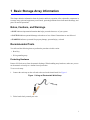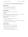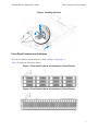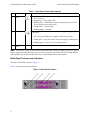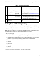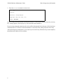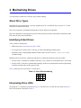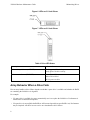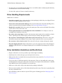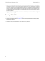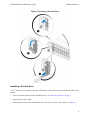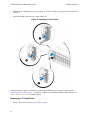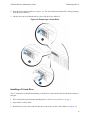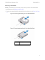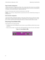
1
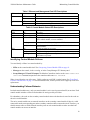
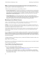
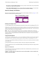
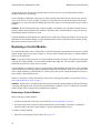
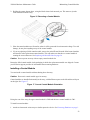
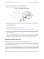
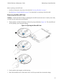
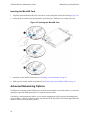
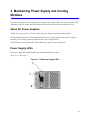
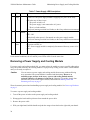
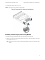
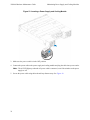
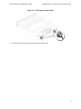
PS4100
Hardware Maintenance Guide
Version 1.0
Copyright 2011 Dell, Inc. All rights reserved.
Dell is a trademark of Dell, Inc.
EqualLogic is a registered trademark.
All trademarks and registered trademarks mentioned herein are the property of their respective owners.
Information in this document is subject to change without notice.
Reproduction in any manner whatsoever without the written permission of Dell is strictly forbidden.
June 2011
Part Number:
110-6063-EN-R1
Table of Contents
1 Basic Storage Array Information............................................................................................................ 1
Notes, Cautions, and Warnings...................................................................................................................................1
Recommended Tools...................................................................................................................................................1
Protecting Hardware ...............................................................................................................................................1
Chassis Types..............................................................................................................................................................2
Array Features.............................................................................................................................................................2
The Bezel ................................................................................................................................................................2
Installing the Bezel..................................................................................................................................................2
Front-Panel Features and Indicators .......................................................................................................................3
Back-Panel Features and Indicators ........................................................................................................................4
Shutting Down and Restarting an Array .....................................................................................................................5
2 Maintaining Drives ................................................................................................................................... 7
About Drive Types......................................................................................................................................................7
Identifying Failed Drives ............................................................................................................................................7
Interpreting Drive LEDs .............................................................................................................................................7
Array Behavior When a Drive Fails ...........................................................................................................................8
Drive Handling Requirements ....................................................................................................................................9
Drive Installation Guidelines and Restrictions ...........................................................................................................9
Removing a 2.5-inch Drive ...................................................................................................................................10
Installing a 2.5-inch Drive ....................................................................................................................................11
Removing a 3.5-inch Drive ...................................................................................................................................12
Installing a 3.5-inch Drive ....................................................................................................................................13
Installing a Drive Blank ........................................................................................................................................14
Removing a Drive Blank.......................................................................................................................................15
3 Maintaining Control Modules ............................................................................................................... 17
Control Module Features ..........................................................................................................................................17
iii
PS4100 Hardware Maintenance Guide
Table of Contents
About Control Module Configurations .................................................................................................................17
Interpreting Control Module LEDs.......................................................................................................................18
Identifying Control Module Failures ....................................................................................................................19
Understanding Failover Behavior .........................................................................................................................19
Maintaining Control Module Firmware................................................................................................................20
Control Module Handling Requirements ..............................................................................................................20
About the Standby On/Off Button ........................................................................................................................21
Replacing a Control Module .....................................................................................................................................22
Removing a Control Module.................................................................................................................................22
Installing a Control Module ..................................................................................................................................23
Replacing the MicroSD Card....................................................................................................................................24
Removing the MicroSD Card ...............................................................................................................................25
Inserting the MicroSD Card ..................................................................................................................................26
Advanced Networking Options.................................................................................................................................26
Configuring the Management Port........................................................................................................................27
4 Maintaining Power Supply and Cooling Modules............................................................................... 29
About AC Power Supplies ........................................................................................................................................29
Power Supply LEDs..................................................................................................................................................29
Removing a Power Supply and Cooling Module......................................................................................................30
Installing a Power Supply and Cooling Module .......................................................................................................31
5 Troubleshooting Your Array................................................................................................................. 35
Safety First—For You and Your array .....................................................................................................................35
Obtaining Technical Support and Customer Service ................................................................................................35
Determining Service Tag Information ......................................................................................................................35
Obtaining Component Diagnostics ...........................................................................................................................36
Troubleshooting Array Startup Failure .....................................................................................................................36
Troubleshooting Loss of Communication.................................................................................................................36
Troubleshooting Array Connections.........................................................................................................................36
iv
PS4100 Hardware Maintenance Guide
Table of Contents
Troubleshooting External Connections.....................................................................................................................36
Troubleshooting Power Supply and Cooling Modules .............................................................................................36
Troubleshooting Array Cooling Problems................................................................................................................37
Troubleshooting Control Modules ............................................................................................................................37
Troubleshooting Hard Drives....................................................................................................................................38
Index............................................................................................................................................................ 39
v
1 Basic Storage Array Information
This chapter includes information about the location and basic operation of the replaceable components in
a storage array, tools and equipment you will need, protecting hardware from electrostatic discharge, and
power on and off operations.
Notes, Cautions, and Warnings
A NOTE indicates important information that helps you make better use of your system.
A CAUTION indicates potential damage to hardware or loss of data if instructions are not followed.
A WARNING indicates a potential for property damage, personal injury, or death.
Recommended Tools
You will need the following items to perform the procedures in this section:
• Bezel key
• Wrist grounding strap
Protecting Hardware
Protect a PS Series array from electrostatic discharge. When handling array hardware, make sure you use
an electrostatic wrist strap or a similar form of protection.
To use a wrist strap:
1. Connect the steel snap on the coil cord to the stud on the elastic band. See Figure 1.
Figure 1 Using an Electrostatic Wrist Strap
2. Fit the band closely around your wrist.
1
PS4100 Hardware Maintenance Guide
Basic Storage Array Information
3. Connect the banana plug to ground, or attach the plug to the alligator clip and connect the clip to a
grounded device such as an ESD mat or the metal frame of a grounded piece of equipment.
Chassis Types
The PS4100 array is available in two different chassis types:
• A 2U chassis with 24 2.5-inch drives, installed vertically
• A 2U chassis with 12 3.5-inch drives, installed horizontally
Array Features
The array has LEDs and other features on both the front and the back.
The Bezel
The bezel is an optional trim panel that attaches to the front of the array to ensure the physical security of
the array. You must remove the bezel to access and maintain the drives.
The bezel has a label that identifies the array model number.
Removing the Bezel
The steps for removing the bezel are the same for all array models.
1. Using the bezel key, unlock the bezel.
2. Holding the bezel, lift the latch on the left side of the bezel and swing the left side away from the array.
3. Lift the right side of the bezel off the right side of the array.
4. Set the bezel aside.
Installing the Bezel
The steps for installing the bezel are the same for all the array models.
1. Hook the right end of the bezel onto the right side of the chassis.
2. Swing the left end of the bezel towards the left side of the chassis.
3. Press the bezel into place until the release latch closes.
4. Using the key provided, lock the bezel and store the key in a safe place.
2
PS4100 Hardware Maintenance Guide
Basic Storage Array Information
Figure 2 Installing the Bezel
Front-Panel Features and Indicators
The front of a PS4100, without the bezel, is shown in Figure 3 and Figure 4.
Table 1 describes the front panel features.
Figure 3 Front Panel Features and Indicators (3.5-inch Drives)
Figure 4 Front Panel Features and Indicators (2.5-inch Drives)
3
PS4100 Hardware Maintenance Guide
Basic Storage Array Information
Table 1 Front Panel Feature Descriptions
Item Indicator
1
Array status
LED
2
Power LED
Icon
Description
The array status LED lights when the array power is on.
• Off—No power.
• Steady blue—Array status is OK.
• Blinking blue—Administrator request to identify the array (see the
Group Administration online help).
• Steady amber—Critical status.
• Blinking amber—Warning.
The power LED is ON when at least one power supply is supplying power
to the array.
• Off—No power (both power supplies are off or not present).
• Steady green—Array has at least one power supply providing power.
3
Drive Release None
Latch
• Blinking green—Array is in power standby mode.
Enables you to remove a drive from the array.
Note: The LEDs are part of a built-in chassis control panel that is not hot-swappable and can be replaced
only by support personnel. During the array power-up sequence, these LEDs will cycle through different
states until the array is fully started and the active control module has been determined.
Back-Panel Features and Indicators
The back of a PS4100 is shown in Figure 5.
Table 2 describes the back panel features.
Figure 5 Back-Panel Features
4
PS4100 Hardware Maintenance Guide
Basic Storage Array Information
Table 2 Array Back Panel Features
Item Feature
Identifier
Description
1
Power switches (one None
on each power supply)
The power switch controls the power supply output to
the array.
2
Power supply and
cooling fan module
PSU0 (left)
700 Watt power supply.
PSU1 (right)
Type 12 Control
Module
CM0 (top)
Control Module
Release Lever
None
For more information, see Power Supply LEDs on page
29.
The control module provides:
• a data path between the array and the applications
using the storage
• array management functions for your array
Enables you to remove the control module from the
array.
3
4
CM1 (bottom)
Shutting Down and Restarting an Array
A PS Series array includes redundant, hot-swappable drives, power supplies, and control modules (in a dual
control module array). You can remove a redundant component without affecting operation if a functioning
component is available. Otherwise, it is recommended that you cleanly shut down the array and turn off
power before removing a component.
Note: When an array is shut down, any volumes with data on the array will be set offline until the array is
successfully restarted. This may affect initiators that are connected to the volumes.
1. Do one of the following:
•
Use telnet or SSH to connect to a functioning IP address assigned to a network interface on the
array. Do not connect to the group IP address.
•
Use the null modem cable shipped with the array to connect to the serial port on the active control
module (ACT LED is green) to a console or a computer running a terminal emulator.
Make sure the serial line characteristics are as follows:
•
9600 baud
•
One STOP bit
•
No parity
•
8 data bits
•
No flow control
2. Log in to an account with read-write access, such as the grpadmin account.
5
PS4100 Hardware Maintenance Guide
Basic Storage Array Information
3. Enter the shutdown command, as shown next.
login: grpadmin
Password:
Welcome to Group Manager
Copyright 2001-2011 Dell, Inc.
group1> shutdown
If you are using a serial connection to shut down an array, it is safe to turn off power when the “press any
key” message appears. (Pressing any key will restart both control modules.)
If you are using a network connection, the session will be disconnected before the array is fully shut down.
Confirm that the ACT LED on each control module is off (not lit) before turning off power to the array.
After performing array maintenance, you can turn on power to the array. When the array restart completes,
the member and volumes will be set online.
6
2 Maintaining Drives
You can replace a failed drive while the array remains running.
About Drive Types
Depending on your configuration, your array supports up to 24 2.5-inch SAS drives or up to 12 3.5-inch
SAS drives in internal drive bays.
Drives are connected to a backplane through drive carriers and are hot-swappable.
Drives are supplied in a carrier that is keyed to fit into specific array models, and cannot be installed in other
Dell arrays or arrays not from Dell Inc.
Identifying Failed Drives
A drive failure is indicated by:
• LEDs on the drive. See Interpreting Drive LEDs.
• A message on the console, in the event log, or in the Group Manager Alarms panel.
• Indications in the Group Manager Member Disks window or the CLI member select show disks
command output.
Behind the bezel, arrays have a label showing the drive numbering for that specific array model:
• In arrays with 2.5-inch drives (installed vertically in a row), the drives are numbered 0-23, left to right.
• In arrays with 3.5-inch drives (installed horizontally), the drives are numbered from left to right and top
to bottom, starting with 0 on the upper left side.
Table 3 shows the drive order for the 3.5-inch drives.
Table 3 3.5-inch Drive Numbering
0
4
8
1 2
3
5 6
7
9 10 11
Interpreting Drive LEDs
The LEDs on a 3.5-inch drive are shown in Figure 6. The LEDs on a 2.5-inch drive are shown in Figure 7.
Drive LED states are described in Table 4.
7
PS4100 Hardware Maintenance Guide
Maintaining Drives
Figure 6 LEDs on 3.5-inch Drives
Figure 7 LEDs on 2.5-inch Drives
Table 4 Drive LED States
Description
Indicator States
Drive activity indicator (ACT LED)
Blinking green: Drive is busy
Drive status indicator (PWR LED)
Steady green: No drive activity
Green: Drive OK
Amber: Drive failed
Off: No power to drive
Array Behavior When a Drive Fails
How an array handles a drive failure depends on whether a spare drive is available and whether the RAID
set containing the failed drive is degraded.
For example:
• If a spare drive is available, the array automatically uses it to replace the failed drive. Performance is
normal after reconstruction completes.
• If a spare drive is not available the RAID set will become degraded (except a RAID 6 set). Performance
may be impaired. A RAID 6 set can survive two simultaneous drive failures.
8
PS4100 Hardware Maintenance Guide
Maintaining Drives
• If a spare drive is not available and the failed drive is in a RAID set that is already degraded, data may
be lost and must be recovered from a backup.
• If a drive fails, replace it. Do not re-install it in the array.
Drive Handling Requirements
Handle drives as follows:
• Store drives properly. Store replacement drives in the packaging in which they were shipped. Do not
stack drives or place anything on top of a drive.
• Protect drives from electrostatic discharge. Wear an electrostatic wrist strap when handling a drive,
unless it is protected from electrostatic discharge. See Protecting Hardware on page 1.
• Handle drives carefully. Hold a drive only by the plastic part of the carrier or the handle. Do not drop
or jolt a drive or force a drive into a slot.
• Warm replacement drives to room temperature before installation. For example, let a drive sit
overnight before installing it in an array.
• Do not leave drive slots empty. Each drive slot in an array must contain a drive assembly or a blank
carrier. Operating an array with an empty slot will void your warranty and support contract.
• Do not remove a functioning drive (other than a spare) from an array. If the drive is not a spare,
the RAID set may become degraded. If you remove a spare, replace the drive as soon as possible.
• Do not remove a drive from its carrier. This action will void your warranty and support contract.
• Keep the shipping material. Return a failed drive to your array support provider in the packaging in
which the replacement drive was shipped. Shipping drives in unauthorized packaging may void your
warranty.
Drive Installation Guidelines and Restrictions
• Replace a failed drive as soon as possible to provide the highest availability.
• Install only drives of the same type, speed, and spin rate in an array.
• Make sure the drive is oriented in the correct position for the array model. See Front-Panel Features
and Indicators on page 3.
• You can use drives of different capacities in the same array. However, the smallest drive in the array
will determine how much space can be used on each drive. For example, if the smallest drive is 400GB,
only 400GB of space will be available for use on each drive.
• Make sure to insert a drive fully in the chassis before pushing in the handle.
• When correctly installed, a drive will be flush with the front of the array. If the drive is protruding from
the array, reinstall the drive.
• After installation, make sure the drive power LED is green or flashing green. See Identifying Failed
Drives on page 7.
9
PS4100 Hardware Maintenance Guide
Maintaining Drives
• There is a two-minute delay between the time you insert a drive and the time the drive is automatically
configured into a RAID set. This time interval allows multiple drives to be simultaneously configured
in an array, which is more efficient than installing a single drive, configuring it, and then repeating the
process. For example, when you install a drive, the timer starts. If no other drives are installed, the drive
is configured after a delay of two minutes. If you install another drive before two minutes have elapsed,
the timer is restarted.
• If you install a drive during RAID reconstruction or verification, the new drive will not be configured
until the operation completes.
Removing a 2.5-inch Drive
1. Remove the bezel. See Removing the Bezel on page 2.
2. Press the release button (callout 1 in Figure 8). The drive latch opens and the drive emerges partway
from the array (callout 2).
3. Pull the drive out by the handle until it is free of the drive bay (callout 3).
10
PS4100 Hardware Maintenance Guide
Maintaining Drives
Figure 8 Removing a 2.5-Inch Drive
Installing a 2.5-inch Drive
The 2.5-inch drives are installed vertically, with the drive release latch on the top and the drive label on the
bottom.
1. Wear electrostatic protection when handling a drive. See Protecting Hardware on page 1.
2. Open the drive release latch.
3. Hold the drive by the carrier and slide the drive most of the way into a slot (callout 1 in Figure 9).
11
PS4100 Hardware Maintenance Guide
Maintaining Drives
4. Push the drive completely into the slot (callout 2). The drive handle will begin to close onto the drive
(callout 3).
5. Push in the handle until you hear a click (callout 4).
Figure 9 Installing a 2.5-inch Drive
Verify that the new drive is operational by examining the LEDs on the front panel, as described in
Interpreting Drive LEDs on page 7. In addition, examine the GUI Member Disks window and the CLI
member select show disks command output.
Removing a 3.5-inch Drive
1. Remove the bezel. See Removing the Bezel on page 2.
12
PS4100 Hardware Maintenance Guide
Maintaining Drives
2. Press the release button (callout 1 in Figure 10). The drive latch opens and the drive emerges partway
from the array (callout 2).
3. Pull the drive out by the handle until it is free of the drive bay (callout 3).
Figure 10 Removing a 3.5-Inch Drive
Installing a 3.5-inch Drive
The 3.5-inch drives are installed horizontally, with the drive release latch to the left and the drive label to
the right.
1. Wear electrostatic protection when handling a drive. See Protecting Hardware on page 1.
2. Open the drive release latch.
3. Hold the drive by the carrier and slide the drive most of the way into a slot (callout 1 in Figure 11).
13
PS4100 Hardware Maintenance Guide
Maintaining Drives
4. Push the drive completely into the slot (callout 2). The drive handle will begin to close onto the drive
(callout 3).
5. Push in the handle until you hear a click (callout 4).
Figure 11 Installing a 3.5-inch Drive
Verify that the new drive is operational by examining the LEDs on the front panel, as described in
Interpreting Drive LEDs on page 7. In addition, examine the GUI Member Disks window and the CLI
member select show disks command output.
Installing a Drive Blank
1. Remove the bezel. See Removing the Bezel on page 2.
2. Insert the drive blank into the drive bay until the blank is fully seated.
3. Attach the bezel.
14
PS4100 Hardware Maintenance Guide
Maintaining Drives
Removing a Drive Blank
Warning: To maintain proper system cooling, all empty drive bays must have drive blanks installed.
1. Remove the bezel. See Removing the Bezel on page 2.
2. Press the release tab and slide the drive blank out until it is free of the drive bay. See Figure 12 or Figure
13.
Figure 12 Removing and Installing a 3.5-Inch Hard-Drive Blank
Figure 13 Removing and Installing a 2.5-Inch Hard-Drive Blank
Item
Description
1
2
Drive blank
Release tab
15
PS4100 Hardware Maintenance Guide
16
Maintaining Drives
3 Maintaining Control Modules
Different PS Series array models contain different control module types. The combination of chassis type,
control module pair, and drives determines the PS Series array model number.
The control modules in a PS Series array contain the PS Series firmware which provides the Group Manager
GUI, the Command Line Reference, and all the array and storage management functions and features.
Ideally, an array has two control modules (which must be of the same type) to avoid a single point of failure
for the array. A PS4100 array includes one or two hot-swappable Type 12 control modules.
One functioning control module is required for array operation. You access control modules from the rear
of the array.
Control Module Features
The Type 12 control module includes:
• Two 1G Ethernet ports, labeled Ethernet 0 and Ethernet 1 (each Ethernet port has two LEDs indicating
status and activity).
• One 10Mb/100Mbps port, labeled MANAGEMENT (for use only if you configure a management
network). The management port has two LEDs to indicate status and activity.
• A column of LEDs labeled PWR (power), ERR (error condition) and ACT (activity) that indicate the
status of the control module.
• A recessed button labeled STANDBY ON/OFF that allows you to quickly shut down the array in certain
circumstances (see About the Standby On/Off Button on page 21 for more information).
• One serial port (for use if there is no network access to the array).
• A field-replaceable microSD card containing the PS Series firmware.
• A release button and latch to release the control module from the array for replacement. The release
lever has a switch that detects activation and prompts the array to save data to non-volatile storage,
thereby protecting your data.
Do not mix control module types in an array. Always make sure both control modules are the same type and
color. See the latest PS Series Release Notes for information about other supported control modules.
About Control Module Configurations
While an array can run using only one control module, it is not recommended as this creates a single point
of failure. If the control module fails and there is no other to take over, all access to your volumes stops until
you replace it.
Only one control module is active (serving network traffic) at one time. The secondary (redundant) control
module mirrors cache data from the active control module. If the active control module fails, the secondary
will take over network operations.
17
PS4100 Hardware Maintenance Guide
Maintaining Control Modules
Single Controller Configuration
A single control module is a single point of failure. If the control module fails, the entire array (and all the
volumes on it) becomes unavailable. Dell strongly recommends buying an array with two control modules,
or installing a second control module in a single-controller array.
In an array with a single control module, the module must be in slot CM0.
Caution: For proper array cooling and airflow requirements, there must be a blank filler in the empty control module slot.
Dual Controller Configuration
A dual control module configuration eliminates a single point of failure in the array. If the active control
module fails, the secondary control module takes over immediately with no interruption of service. This
gives you time to replace the failed control module while your volumes and data remain accessible.
Interpreting Control Module LEDs
Control modules have the following LEDs:
• The Ethernet ports and the Management port each have two green LEDs that indicate the port's status
and activity.
• Below the release latch is a column of three LEDs that indicate the status of the entire control module.
Figure 14 Control Module LEDs
18
PS4100 Hardware Maintenance Guide
Maintaining Control Modules
Table 5 Ethernet and Management Port LED Descriptions
LED Location
State
Description
Left
Off
On
Off
On
No power or not connected to network.
Connected to network.
No power, not transmitting, or not receiving.
Transmitting or receiving.
Right
Table 6 Control Module Status LED Descriptions
LED Name
State
PWR
Off
No power.
On (steady green) Power/OK.
Off
No power, secondary control module is not synchronized with
active control module, or error condition.
ACT
Steady green
Steady amber
ERR
Off
Steady red
Blinking red
Description
Active control module (serving network I/O).
Secondary control module. Cache is synchronized with active
control module.
Normal operation or no power.
Array is starting up or error condition.
Array is entering power standby mode because the Standby On/
Off button was pressed.
Identifying Control Module Failures
You can identify a failure in a control module by:
• LEDs on the control module itself. See Interpreting Control Module LEDs on page 18.
• Messages on the console, in the event log, or in the Group Manager GUI Alarms panel.
• Group Manager GUI and CLI output. The Member Controllers window or the member select show
controllers command output shows the control module status not installed.
When viewed from the rear of the array, CM0 is on the top, and CM1 is on the bottom. See Front-Panel
Features and Indicators on page 3. If a control module fails, contact your PS Series support provider for a
replacement.
Understanding Failover Behavior
In a dual control module array, only one control module is active (serving network traffic) at one time. Each
control module includes a cache-to-flash module for storing recently-used data.
For redundancy, the cache on the secondary control module mirrors the data that is stored in the cache on
the active control module.
The active control module can use network interfaces on the secondary control module if there is a cable
connected from the corresponding port on the secondary control module to a network switch. Therefore, you
should connect cables to all the network interface ports on each control module to make sure that both
control modules can access an interface.
19
PS4100 Hardware Maintenance Guide
Maintaining Control Modules
Note: The management ports on the control modules do not fail over if one control module fails.
Therefore, if you are using a dedicated management network, make sure the management ports on both
control modules are connected to the management network.
A PS series array provides two types of network failure protection:
• Network connection failover. If multiple network interfaces are configured and one network interface
fails, iSCSI initiators that were connected to the failed interface can reconnect to the group IP address
and be redirected to a functioning interface. For example, in a single control module array, if Ethernet
0 and Ethernet 1 are connected to a network, and Ethernet 0 fails, initiators that were connected to
Ethernet 0 can be redirected to Ethernet 1.
• Control module failover. In a dual control module array, if the active control module fails, the
secondary automatically takes over and becomes active. If a cable is connected to the port on the newly
active control module, network I/O can continue through that interface. Control module failover is
transparent to applications, but iSCSI initiators must reconnect to the group IP address.
Maintaining Control Module Firmware
A Type 12 control module has a microSD card running the array firmware. You should run the latest
firmware version to take advantage of new product features and enhancements.
Caution: In a dual control module array, both control modules must be running the same firmware version; otherwise, only one control module will be functional. When you update the array firmware, both control modules are updated to the same firmware version.
Group members should run the same firmware version; otherwise, only the functionality common to all
versions will be available in the group. See the PS Series Release Notes for information about mixedfirmware groups.
If you are adding a second control module, upgrading a control module, or replacing a failed microSD card,
contact your PS Series support provider for a replacement. Inform your provider of the current PS Series
firmware version on your system. If you are replacing a failed control module, remove the microSD card
from the failed control module and install it in the replacement control module. This will make sure that you
keep the correct firmware.
To display the firmware version running on an array, examine the GUI Member Controllers window or use
the following CLI command:
member select show controllers
If the firmware on a microSD card does not match the firmware running on an array, do not install it. Instead,
contact your array support provider.
Control Module Handling Requirements
Follow these control module handling requirements:
• Protect control modules from electrostatic discharge. Always wear an electrostatic wrist strap when
handling a control module, as described in Protecting Hardware on page 1.
• Do not remove a control module from an array while the control modules are synchronizing.
When synchronization completes, a console message will appear. Also, the ACT LED on the secondary
control module will be orange.
20
PS4100 Hardware Maintenance Guide
Maintaining Control Modules
• Do not leave a control module slot empty. In an array with one control module, always attach a blank
face plate to the empty control module slot.
• Store control modules properly. Store a control module in its original packaging or in an anti-static
bag or place the control module on a surface protected from electrostatic discharge.
About the Standby On/Off Button
The Type 12 control module has a small, recessed button labeled Standby ON/OFF (see Figure 15). The
button is recessed to prevent accidental activation.
Figure 15 Standby Button Location
Enabling the Standby Feature
To use the standby button, a group administrator must enable the feature in the Group Manager GUI or CLI.
Enabling the use of the button applies group-wide; that is, it allows you to press the button to shut down any
member (array) that has the button (currently, PS4100 and PS6100 array models only). You do not need to
enable use of the button on each member separately.
Note: Only a user with group administrator privileges can enable the standby feature on the group.
However, anyone can press the button, and the group cannot determine who put the array into standby on/
off mode. Therefore, group administrators should consider their environment's security concerns before
enabling this feature.
Using the Standby Button
After the feature is enabled group-wide, you can use the Standby On/Off button on either control module of
any applicable member to shut down the array quickly without using the Group Manager GUI or CLI.
You must press in and hold the Standby On/Off button for at least two (2) seconds to shut down the member
to the standby state.
(To fully shut down the array, turn off the switches on the power supply and cooling modules.)
To turn the member back on, press and hold the Standby On/Off button again (if the power supply switches
are turned on).
Important Considerations
Use this button only in when you must shut down a member fast, in situations where you do not have access
to the Group Manager GUI or CLI.
Caution: In standby mode, any volumes that use space on that member or that are bound to that
member become unavailable!
21
PS4100 Hardware Maintenance Guide
Maintaining Control Modules
All operations on the member are suspended, there is no I/O activity to or from the member, and the
member's firmware is not running.
Use the Standby On/Off button only when you need to quickly shut down an array and you may not have
access to the GUI or CLI; for example, if you discover a problem in your lab environment, such as high
temperature or a water leak that may damage the array, that requires you to shut down the array as soon as
possible.
Caution: Do not shut down the array (with the standby on/off button or by any other method) before replacing a failed control module! If the member is shut down and a controle module is removed, the array
automatically returns to full-power mode.
Using the Standby On/Off button on one member does not affect any other group members. You must press
the button on each member that has it. Group members that do not have the button remain online; to shut
them down, you must use the GUI or CLI.
Replacing a Control Module
If a control module fails, remove it and replace it with a functioning control module. Do not remove a failed
control module until you are ready to replace it. You may need to temporarily remove a control module to
replace its microSD card.
Note: For proper cooling, do not leave a control module slot empty. If an array will operate for a long time
with only one control module, you must install a blank in the empty slot. You can order a control module
blank from your PS Series array service provider.
You can partially or completely remove a control module without shutting down the array if the remaining
control module has at least one connected and functioning network interface. However, if you remove the
active control module (the LED labeled ACT will be green), there will be a short interruption as failover to
the secondary control module occurs.
Otherwise, if possible, cleanly shut down the array before removing the module, as described in Shutting
Down and Restarting an Array on page 5.
Caution: Do not remove a control module from an array while the control modules are still synchronizing.
A message will appear on the console when synchronization completes. The ACT LED on the secondary
control module will be orange when synchronization completes.
Removing a Control Module
Before removing a control module:
• Attach an electrostatic wrist strap, as described in Protecting Hardware on page 1.
• Disconnect any serial or network cables attached to the control module. Optionally, re-attach the
network cables to the other control module to provide uninterrupted data access.
To remove a control module:
1. Push down on the orange release button. See Figure 16.
22
PS4100 Hardware Maintenance Guide
Maintaining Control Modules
2. Holding the orange button down, swing the black release latch towards you. This starts to eject the
control module from the array.
Figure 16 Removing a Control Module
3. Place the control module on a flat surface where it will be protected from electrostatic charge. To avoid
damage, do not place anything on top of the control module.
4. If you are replacing a failed control module, remove the microSD card from the failed control module
and install it in the replacement control module. This will make sure that the new control module is
running the correct firmware. See Replacing the MicroSD Card on page 24.
Caution: Do not operate an array with an empty control module slot.
Return the failed control module in the packaging in which the replacement module was shipped. Contact
your PS Series support provider for information about returning hardware.
Installing a Control Module
You can install a control module without shutting down the array.
Caution: Do not mix control module types in an array.
Control modules are installed horizontally in the array, with the Ethernet ports on the left and the serial port
on the right. See Figure 17.
Figure 17 Correct Control Module Orientation
Facing the rear of the array, the upper control module is CM0 and the lower control module is CM1.
To install a control module:
1. Attach an electrostatic wrist strap or a similar protective device. See Protecting Hardware on page 1.
23
PS4100 Hardware Maintenance Guide
Maintaining Control Modules
2. Push down on the orange release tab and swing the black lever out.
3. Slide the control module into the chassis until you feel resistance.
Figure 18 Installing a Control Module
4. Rotate the black lever inward, which pushes the control module completely into the slot. The latch on
the lever will snap into place.
5. Reconnect the network cables.
6. If the array was shut down, turn on power to the array.
7. Make sure the control module is operational. See Interpreting Control Module LEDs on page 18.
When connected, the control module cache-to-flash module receives full charge. If it cannot be charged,
its status is reported as BAD in the Group Manager GUI. You must remove the control module and
replace it with another one.
If two control modules are installed but only one is shown in the GUI or CLI, the control module may
not be properly installed. Reinstall the control module. If both control modules still are not shown in the
GUI or CLI, they may not be running the same firmware. Contact your array support provider.
Replacing the MicroSD Card
Each control module includes a microSD card that contains the PS Series firmware.
If a control module fails, remove the microSD card from the failed control module and install the card in the
replacement control module. This will make sure that the new control module is running the same firmware
as the other control module in the array.
You can remove a control module without shutting down the array if the remaining control module has at
least one connected and functioning network interface. If you remove the active control module (the LED
labeled ACT will be green), there will be a short interruption as failover to the secondary control module
occurs.
When you remove the control module, place it on a surface that is protected from electrostatic discharge.
24
PS4100 Hardware Maintenance Guide
Maintaining Control Modules
Before replacing a microSD card:
• Attach an electrostatic wrist strap, as described in Protecting Hardware on page 1.
• See Replacing a Control Module on page 22 for instructions on removing a control module.
Removing the MicroSD Card
Caution: To reduce the risk of losing or damaging the microSD card, do not remove it until you are ready
to install it in the replacement control module.
1. Firmly push the card into its housing to release the spring mechanism (Figure 19). The microSD card
will be partially ejected from the housing.
Figure 19 Ejecting the MicroSD Card
2. Gently pull the card straight out of the housing.
3. Place the microSD card on a flat surface where it will be protected from electrostatic charge.
25
PS4100 Hardware Maintenance Guide
Maintaining Control Modules
Inserting the MicroSD Card
1. Align the replacement microSD card so the arrow on the card points towards the housing (Figure 20).
2. Firmly press the card into the housing until it clicks into place. Make sure you cannot pull it out.
Figure 20 Inserting the MicroSD Card
3. Install the control module in the array. See Installing a Control Module on page 23.
4. Make sure the control module is operational. See Interpreting Control Module LEDs on page 18.
Advanced Networking Options
In addition to connecting all the Ethernet ports on both control modules to network switches, you can also
optionally connect the Management port to a separate network switch.
Configuring a management port enables you to separate management traffic (creating and managing the
group, members, volumes, replication, and so on) from the iSCSI data traffic (I/O between applications and
volumes, and between replication partners).
26
PS4100 Hardware Maintenance Guide
Maintaining Control Modules
Configuring the Management Port
Configuring the 10/100Mbps management port involves hardware steps and software steps. The
management port is restricted to group management traffic only; it will not carry iSCSI I/O.
Note: This is considered an advanced configuration, available if your environment requires this level of
security.
Hardware Steps
1. Make sure your network environment can support a dedicated management network, with a subnet that
is separate from the subnets for iSCSI traffic.
2. On both control modules, connect the port labeled MANAGEMENT to the management network.
Software Steps
See the Group Administration guide for the procedure to configure the management network in the Group
Manager GUI.
27
PS4100 Hardware Maintenance Guide
28
Maintaining Control Modules
4 Maintaining Power Supply and Cooling
Modules
The array can support two hot-swappable power supply and cooling modules. The array can operate only
temporarily with one module, but both modules must be present for long-term cooling of the array.
About AC Power Supplies
The PS Series array receives A/C power from two power supply and cooling modules (PSUs).
The fans that keep the array cool are integrated into the power supply modules and cannot be replaced
separately. If a fan fails, you must replace the entire power supply module.
The PS4100 has two 700 Watt PSUs. Each 700W power supply has two cooling fans.
Power Supply LEDs
The power supply and cooling modules have LEDs that indicate their status.
See Figure 21 and Table 7.
Figure 21 700W Power Supply LEDs
29
PS4100 Hardware Maintenance Guide
Maintaining Power Supply and Cooling Modules
Table 7 Power Supply LED Descriptions
Item LED
1
Color
DC
Green
power
State
ON—Normal operation. Power supply is connected to AC power and the power
switch is on. The power supply module is supplying DC power to the array.
OFF when any of these is true:
• The power switch is off
• The power supply is not connected to AC power
• There is a fault condition
2
Fault
For a list of warning or critical level faults, see the Group Administration manual.
Amber On—Fault detected.
OFF—OK.
Blinks briefly when power is first turned on to the power supply module.
For a list of warning or critical level faults, see the Group Administration manual.
3
AC
Green
power
ON—Power supply module is connected to a source of AC power whether or not
the power switch is on.
OFF—Power supply module is completely disconnected from any source of AC
power.
Under normal conditions, the AC and DC power LEDs will be lit at the same time.
Removing a Power Supply and Cooling Module
If a power supply and cooling module fails, you must replace the module as soon as possible, although an
array can operate with only one working module. For proper array cooling, do not remove a failed module
until you are ready to replace it.
Caution
You can remove a power supply and cooling module from an array without affecting
array operation if the second module is installed and functioning. However, to
maintain proper air flow in the array, a power and cooling module must be
replaced within five (5) minutes of removing it. Otherwise, if possible, cleanly shut
down the array before removing the module, as described in Shutting Down and
Restarting an Array on page 5.
Wear electrostatic protection when handling a power supply and cooling module. See Protecting Hardware
on page 1.
To remove a power supply and cooling module:
1. Turn off the power switches on the power supply and cooling module.
2. Disengage the hook-and-loop fastener from around the power cable.
3. Remove the power cable.
4. With your right hand, hold the handle and push the orange release latch to the right with your thumb.
30
PS4100 Hardware Maintenance Guide
Maintaining Power Supply and Cooling Modules
5. Pull the module from the slot. See Figure 22.
Caution: The module is heavy; support it with two hands.
Figure 22 Removing a Power Supply and Cooling Module
Installing a Power Supply and Cooling Module
1. Hold the power supply module so that the orange release latch is on the upper left.
2. Slide the power supply and cooling module into the chassis until it is fully seated and the release latch
clicks into place. See Figure 23.
Note: Before the power cable is connected, the fans start spinning, powered by the other power supply
module.
31
PS4100 Hardware Maintenance Guide
Maintaining Power Supply and Cooling Modules
Figure 23 Inserting a Power Supply and Cooling Module
3. Make sure the power switch is in the OFF position.
4. Connect the power cable to the power supply and cooling module and plug the cable into a power outlet.
Note: The AC LED lights up when the AC power cable is connected, even if the switches on the power
supply are off.
5. Secure the power cable using the hook-and-loop fastener strap. See Figure 24.
32
PS4100 Hardware Maintenance Guide
Maintaining Power Supply and Cooling Modules
Figure 24 : Securing the Power Cable
6. Turn on the switches on the power supply and cooling module.
33
PS4100 Hardware Maintenance Guide
34
Maintaining Power Supply and Cooling Modules
5 Troubleshooting Your Array
Safety First—For You and Your array
Many repairs may only be done by a certified service technician. You should only perform troubleshooting
and simple repairs as authorized in your product documentation, or as directed by the online or telephone
service and support team. Damage due to servicing that is not authorized by Dell is not covered by your
warranty. Read and follow the safety instructions that came with the product.
Obtaining Technical Support and Customer Service
Dell’s support service is available to answer your questions about PS Series SAN arrays. If you have an
Express Service Code, have it ready when you call. The code helps Dell's automated-support telephone
system direct your call more efficiently.
Contacting Dell
Dell provides several online and telephone-based support and service options. Availability varies by country
and product, and some services might not be available in your area.
For customers in the United States, call 800-945-3355.
Note: If you do not have access to an Internet connection, contact information is printed on your invoice,
packing slip, bill, or Dell product catalog.
Use the following procedure to contact Dell for sales, technical support, or customer service issues:
1. Visit support.dell.com.
2. Verify your country or region in the Choose A Country/Region drop-down menu at the bottom of the
window.
3. Click Contact Us on the left side of the window.
4. Select the appropriate service or support link based on your need.
5. Choose the method of contacting Dell that is convenient for you.
Determining Service Tag Information
Each array has a service tag with a number. You may need to provide this information to customer support
when you contact us. The service tag label is visible on the front of the PS4100, on the right bezel latch
block.
35
PS4100 Hardware Maintenance Guide
Troubleshooting Your Array
Obtaining Component Diagnostics
You can collect diagnostic information for one or more members of a PS Series group through the Group
Manager GUI or the CLI. See the Group Administration guide or the CLI Reference for more information.
Troubleshooting Array Startup Failure
If your system halts during startup, check if:
• The array fault LEDs are lit. See Front-Panel Features and Indicators on page 3.
• There is a constant scraping or grinding sound when you access the hard drive. See Obtaining Technical
Support and Customer Service on page 35.
Troubleshooting Loss of Communication
For information about troubleshooting loss of communication, see Network Requirements and
Recommendations in the Installation Guide for your array.
Troubleshooting Array Connections
1. Verify that the control module port link status LED and the control module status LED are solid green
for each port that is connected to a cable. If the LEDs are not solid green, see Control Module Features
on page 17.
2. Make sure that all the cables are attached correctly.
If the problem is not resolved, see Obtaining Technical Support and Customer Service on page 35.
Troubleshooting External Connections
• Verify that the cables are connected to the correct Ethernet and, if applicable, Management ports before
troubleshooting any external devices. For the location of the back-panel connectors on your array, see
Back-Panel Features and Indicators on page 4.
• Make sure that the power cables are securely attached to the power supply modules on your array.
Troubleshooting Power Supply and Cooling Modules
1. Locate the faulty power supply and determine the status of the LEDs.
If the AC power LED is not lit, check the power cord and power source into which the power supply is
plugged.
36
–
Connect another device to the power source to verify if it is working.
–
Connect the cable to a different power source.
PS4100 Hardware Maintenance Guide
–
Troubleshooting Your Array
Replace the power cable.
If the problem is not resolved, or if the power supply’s fault indicator is lit, see Obtaining Technical
Support and Customer Service on page 35.
Power supply and cooling modules are hot-swappable. The array can operate on a single power supply;
however both modules must be installed to ensure proper cooling. A single power supply and cooling
module can be removed from a powered-on array for a maximum of five minutes. Beyond that time, the
array may automatically shut down to prevent damage.
2. Reseat the power supply by removing and reinstalling it. See Removing a Power Supply and Cooling
Module on page 30.
Note: After installing a power supply, allow several seconds for the array to recognize the power supply
and to determine if it is working properly.
If the problem is not resolved, see Obtaining Technical Support and Customer Service on page 35.
Troubleshooting Array Cooling Problems
Check for and correct any of the following situations:
• Empty drive bays (no drive or drive blank).
• Ambient temperature is too high. See the Technical Specifications for the array in the Installation and
Setup Guide.
• External airflow is obstructed.
• The power supply and cooling module is removed or has failed. See Troubleshooting Power Supply and
Cooling Modules on page 36.
If the problem is not resolved, see Obtaining Technical Support and Customer Service on page 35.
Troubleshooting Control Modules
1. Remove the control module and verify that the pins on the backplane and control module are not bent.
See Replacing a Control Module on page 22.
2. Reinstall the control module and wait for 30 seconds. See Replacing a Control Module on page 22.
3. Check the control module status LEDs. See Interpreting Control Module LEDs on page 18 for more
information.
4. If control module status LED is blinking amber (5 times per sequence), update the firmware to the latest
supported firmware on both the control module. For more information about downloading the latest
firmware, see the PS Series Release Notes and the document Updating PS Series Storage Array
Firmware, available on the customer support site.
5. If the link status LEDs are not green:
a. Reseat the cables on the control modules and the switches.
37
PS4100 Hardware Maintenance Guide
Troubleshooting Your Array
b. Check the link status LED. If the link status LED is not green, proceed to the next step.
c. Replace the cables.
If the problem is not resolved, see Obtaining Technical Support and Customer Service on page 35.
Troubleshooting Hard Drives
Check the hard drive indicators before removing the faulty drive from the array.
1. Remove the drive from the array. See Identifying Failed Drives on page 7.
2. Check the drive to make sure that the connectors are not damaged.
3. Reinstall the drive.
4. Verify that the control module port link status LED and the control module status LED are solid green
for each port that is connected to a cable. If the LEDs are not solid green, see Interpreting Control
Module LEDs on page 18.
If the problem is not resolved, see Obtaining Technical Support and Customer Service on page 35.
38
Index
array
removing from array .................... 22
control module restriction ............23
restriction on mixing .................... 23
control modules ............................17
restrictions ................................... 17
cooling ..........................................29
supported disk type ...................... 23
fans ...............................................29
synchronizing ......................... 20, 22
firmware .......................................20
types ............................................. 23
LEDs ........................................7, 18
verifying operational status ......... 24
power supplies ..............................29
shutdown procedure .......................5
bezel
cooling
removing ...................................... 30
disks
installing .........................................2
failure behavior .............................. 8
removing ........................................2
failure indications .......................... 7
control modules
handling requirements ................... 9
batteries ........................................17
LEDs .............................................. 7
checking proper installation .........24
locating .......................................... 7
failover behavior ..........................19
protecting ....................................... 9
failure indications .........................19
verifying operational status ... 12, 14
features .........................................17
electrostatic discharge, avoiding ...... 1
firmware requirements .................20
electrostatic wrist strap, using .......... 1
firmware version ..........................20
failover
handling requirements ..................20
control module ....................... 19–20
installing in array .........................23
network connection ...................... 20
LEDs ............................................18
locating .........................................19
failure indications
control modules ........................... 19
39
PS4100 Hardware Maintenance Guide
disks ...............................................7
fans
removing ......................................30
firmware
identifying version .......................20
requirements .................................20
front panel
features ...........................................3
identifying the firmware version ....20
indicators
power ..............................................3
installing
Index
network interfaces
LEDs ............................................ 18
power indicators ............................... 3
power supplies
removing ...................................... 30
PS Series array
protecting from discharge .............. 1
recommended tools .......................... 1
removing
3.5-inch drive ......................... 10, 12
drive blank ................................... 15
requirements
drive blank ....................................14
control modules ........................... 20
front bezel ......................................2
cooling ......................................... 30
power supply/cooling fan module 31
disks ............................................... 9
LEDs
firmware ....................................... 20
control module .............................18
power ........................................... 30
disks ...............................................7
safety .............................................. 35
network interfaces ........................18
shutting down an array ..................... 5
microSD card
status
firmware requirements .................20
control modules ........................... 19
inserting ........................................26
troubleshooting ............................... 35
removing ......................................25
connections .................................. 36
replacing .......................................20
cooling problems ......................... 37
network
failure protection ..........................20
40
external connections .................... 36
hard drives ................................... 38
PS4100 Hardware Maintenance Guide
Index
loss of communication .................36
power supply/cooling fan module 36
startup failure ...............................36
41