1
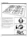
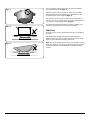
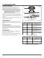
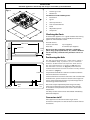
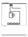
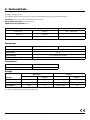
RGG60 Gas Hob User Guide & Installation & Service Instructions U109927 - 04 Contents 1. Before You Start... 1 2. Hob Overview 3 3. Cleaning Your Hob 5 4.Troubleshooting 6 5.Installation 7 6. Conversion to LPG Gas 11 7. Circuit Diagram 12 8. Technical Data 13 9. Warranty/After Sales Service 14 1. Before You Start... DocNo.011-0001 - Introduction gas Personal Safety Thank you for buying a Rangemaster hob. It should give you many years trouble-free cooking if installed and operated correctly. It is important that you read this section before you start, particularly if you have not used a gas hob before. Accessible parts will become hot during use and will retain heat even after you have stopped cooking. Keep babies and children away from the hob and never wear loose-fitting or hanging clothes while the appliance is in use. This appliance is designed for domestic cooking only. Using it for any other purpose could invalidate any warranty or liability claim. In particular, the oven should NOT be used for heating the kitchen – besides invalidating claims, this wastes fuel and may overheat the control knobs. When the hob is not in use make sure that the control knobs are in the OFF position. DO NOT use hotplate protectors, foil or hotplate covers of any description. These may affect the safe use of your hotplate burners and are potentially hazardous to health. Installation and Maintenance In the UK, the hob must be installed by a CORGI registered gas engineer. The electrical installation should be in accordance with BS 7671. Otherwise, all installations must be in accordance with the relevant instructions in this booklet, with the relevant national and local regulations, and with the local gas and electricity supply company requirements. Always keep combustible materials, e.g. curtains, and flammable liquids a safe distance away from your hob. Do not spray aerosols in the vicinity of the hob while it is on. Use dry oven gloves when applicable – using damp gloves might result in steam burns when you touch Make sure that the gas supply is turned on and that the hob is wired in and switched on (the hob needs an electricity supply for ignition). a hot surface. Do not use a towel or other bulky cloth in place of a glove – it might catch fire if brought into contact with a hot surface. Only a qualified service engineer should service the hob and only approved spare parts should be used. Never operate the hob with wet hands. Never heat unopened food containers. Pressure build up may make the containers burst and cause Always allow the hob to cool and then switch it off at the mains before cleaning or carrying out any maintenance work, unless specified otherwise in this guide. injury. Do not use unstable saucepans. Always ensure that you position the handles away from the edge of the Peculiar Smells Make sure the room is well ventilated to the outside air (see ‘Ventilation’ below). People with respiratory problems should vacate the area for this brief period. hotplate. Never leave the hotplate unattended at high heat settings. Pans boiling over can cause smoking, and greasy spills may catch on fire. Use a deep fat thermometer whenever possible to prevent fat overheating beyond the smoking point. If You Smell Gas • Do not turn electric switches on or off • Do not smoke • Do not use naked flames • Do turn off the gas at the meter or cylinder • Do open doors and windows to get rid of the gas • Do keep people away from the area affected • Call your gas supplier If you are using natural gas in the UK ring the National Grid on: 0800 111 999. Never leave a chip pan unattended. Always heat fat slowly, and watch as it heats. Deep fry pans should be only one third full of fat. Filling the pan too full of fat can cause spill over when food is added. If you use a combination of oils or fats in frying, stir them together before heating, or as the fats melt. Foods for frying should be as dry as possible. Frost on frozen foods or moisture on fresh foods can cause hot fat to bubble up and over the sides of the pan. Carefully watch for spills or overheating of foods when frying at high or medium high temperatures. Never try to move a pan of hot fat, especially a deep fat fryer. Wait until the fat is cool. Ventilation CAUTION: Using a gas cooking appliance will result in the production of heat and moisture in the room in which it is installed. Make that the kitchen is well ventilated; keep natural ventilation holes open or install a powered cooker hood that vents outside. If you have several burners on or use the hob for a long time, open a window or turn on an extractor fan. Do not use water on grease fires and never pick up a flaming pan. Turn off the controls and then smother a flaming pan on a surface unit by covering the pan completely with a well fitting lid or baking tray. If available, use a multi-purpose dry chemical or foamtype fire extinguisher. 1 Take care that no water seeps into the appliance. Only certain types of glass, glass-ceramic, earthenware or other glazed containers are suitable for hotplate cooking; others may break because of the sudden change in temperature. Cleaning In the interests of hygiene and safety, the hob should be kept clean at all times as a build up of fats and other foodstuffs could result in a fire. Clean only the parts listed in this guide. Clean with caution. If a wet sponge or cloth is used to wipe spills on a hot surface, be careful to avoid steam burns. Some cleaners can produce noxious fumes if applied to a hot surface. 2 2. Hob Overview DocNo.021-0003 - Overview RGG60 gas Fig.2-1 ArtNo.316-0018 RGG60 iso view The diagram by each of the control knobs indicates which burner that knob operates (Fig.2-1). Each burner has a special Flame Safety Device (FSD) that stops the flow of gas if the flame goes out. Fig.2-2 To light a burner, push in and turn the associated control knob anti-clockwise (Fig.2-2) to the ‘high’ position indicated by the large flame symbol []. Keep the knob pressed down for 3-5 seconds to let the gas through to the burner. The igniter should spark and light the gas. ArtNo.316-0022 RGG60 hob control to high If, when you let go of the control knob the burner goes out, then the safety device has not held in. Turn the control to the off position and wait one minute then try again, this time holding in the control knob for slightly longer. Fig.2-3 Adjust the flame to suit by turning the control knob clockwise (Fig.2-3). Ensure that the flames are under the pans. Using a lid will help the contents boil more quickly (Fig.2-4). ArtNo.316-0023 RGG60 hob control to low Large pans should be spaced well apart. Fig.2-4 ArtNo.311-0001 Right pans gas 3 Pans and kettles with concave bases or down turned base rims should not be used (Fig.2-5). Fig.2-5 Simmering aids, such as asbestos or mesh mats, are NOT recommended. They will reduce burner performance and could damage the pan supports (Fig.2-6). ArtNo.311-0002 Pan with rim You should also avoid using unstable and misshapen pans that may tilt easily, and pans with a very small base diameter, e.g. milk pans, single egg poachers (Fig.2-7). The minimum recommended pan diameter is 120mm. The maximum allowable pan base diameter is 250mm. Fig.2-6 Hob Care The burner parts can be removed for cleaning; see ‘Cleaning your hob’. You should wipe the top surface of the hob around the hotplate burners as soon as possible after spills occur. Try to wipe any spills off while the hob is still warm. Art No. 311-0003 Simmer aids Note: The use of aluminium pans may cause metallic marking of the pan supports. This does not affect the durability of the enamel and may be cleaned off with an appropriate metal cleaner. Fig.2-7 ArtNo.311-0004 Tipping wok 4 3. Cleaning Your Hob DocNo.041-0001 - Cleaning - BI hob gas 4-element Essential information Fig.3-1 Allow the cooker to cool and then isolate the electricity supply before carrying out any thorough cleaning. A Never use paint solvents, washing soda, caustic cleaners, biological powders, bleach, chlorine based bleach cleaners, coarse abrasives or salt. Do not mix different cleaning products – they may react together with hazardous results. C B All parts of the hob can be cleaned with hot soapy water – but take care that no surplus water seeps into the appliance. E Remember to switch on the electricity supply before re-using the cooker. F D ArtNo.316-0007 Gas burner Regular cleaning is recommended. For easier cleaning, wipe away any spillages immediately. Hotplate Burners A – Cap, B – Head, C – Notch, D – Base, E – FSD , F – Electrode The burner heads and caps can be removed for cleaning (Fig.3-1). Make sure they are absolutely dry before replacing them. Part The single ring burners Finish Recommended cleaning method Hotplate top Stainless steel or glass Hot soapy water and a soft cloth. remove stubborn stains gently with a nylon scourer. Pan supports Enamel coated cast iron Cif cream cleaner and a nylon scourer; dishwasher. Cleaning Table Burner caps Enamel Refer to the cleaning tables (Table 3-1 and Table 3-2) for details on cleaning the hob. Cif cream cleaner and a nylon scourer; dishwasher. ArtNo.050-0009 Cleaning table 1 Burner heads Aluminium When refitting the burner head, ensure that the notch and opening lines up with the electrode in the base. Check that the burner head is level and that the cap is fitted centrally on the burner head. The cleaners listed are available from supermarkets or electrical retailers. For enamelled surfaces use a cleaner that is approved fro use on vitreous enamel. Cif cream cleaner or similar with a soft cloth. Take care not to be too vigorous. Table 3-1 Cleaning the hotplate Part Finish Control panel Recommended cleaning method Stainless steel or glass Damp soft cloth. Do not use abrasive cleaners on the lettering. ArtNo.050-0010 Cleaning table 2 Control knobs Plastic and brushed Damp soft cloth. aluminium Table 3-2 Cleaning outside the hotplate 5 4.Troubleshooting If there is an installation problem and I don’t get my original installer to come back to fix it, who pays? You do. Service organisations will charge for their callouts if they are correcting work carried out by your original installer. Therefore, it’s in your own interest to keep track of this installer so that you can contact them as required. Hotplate ignition or hotplate burners faulty Is the power on? If not, there maybe something wrong with the power supply. Are the sparker (ignition electrode) or burner slots blocked by debris? Are the burner trim and caps correctly located? See the section on ‘Cleaning’. Hotplate burners will not light Make sure that the burner parts have been replaced correctly after wiping or removing for cleaning. Check that there is not a problem with your gas supply. You can do this by making sure that other gas appliances you may have are working. Do the burners spark when you turn on the control? If not, check that the power is on. 6 INSTALLATION Check the appliance is electrically safe and gas sound when you have finished. 5.Installation DocNo.061-0003 - Installation - RGG60 gas hob Dear Installer In the Republic of Ireland: The installation must be carried out by a Competent Person and installed in accordance with the current edition of IS 813 “Domestic Gas Installations”, the current Building Regulations and reference should be made to the current ETCI rules for electrical installation. Before you start your installation, please complete the details BELOW. Installer’s Name Provision of Ventilation This appliance is not connected to a combustion products evacuation device. Particular attention shall be given to the relevant requirements regarding ventilation. Installer’s Company ArtNo.050-0011 - Installer information table In the UK: The room containing the hob should have an air supply in accordance with BS 5440 Part 2. All rooms require an openable window or equivalent, while some rooms require a permanent vent in addition to the openable window. The hob should not be installed in a bedsitting room with volume less than 20m³. If it is installed in a room of volume less than 5m³ an air vent of effective area 100cm² is required; if it is installed in a room of volume between 5m³ and 10m³, an air vent of effective area 50cm² is required; while if the volume exceeds 11m³, no air vent is required. Installer’s Telephone Number Appliance Serial Number Should your customer have a problem relating to your installation they will be able to contact you easily. If there are other fuel burning appliances in the same room, BS 5440 Part 2 should be consulted to determine the requisite air vent requirements. You must be aware of the following safety requirements & regulations: Before installing, make sure that the local distribution conditions (nature of the gas and gas pressure) and the adjustment of the appliance are compatible. In the Republic of Ireland: Reference should be made to the current edition of IS 813, which makes clear the conditions that must be met to demonstrate that sufficient ventilation is available. This appliance must be installed in accordance with the regulations in force and only in a well-ventilated space. Read the instructions before installing or using this appliance. Location of the Hob The regulations and standards are as follows: The hob may be installed in a kitchen/kitchen diner but NOT in a room containing a bath or shower. In the UK: In your own interest and that of safety, it is law that all gas appliances be installed by competent persons. CORGI registered installers undertake to work to safe and satisfactory standards. Failure to install the appliance correctly could invalidate any warranty or liability claims and lead to prosecution. Note: An appliance for use on LPG shall not be installed in a room or internal space below ground level, e.g. in a basement. Conversion All models are supplied set for use on group H natural gas. A conversion kit for LP gas is included with the appliance. See the instructions that are supplied with the conversion kit. After converting the appliance please attach the Gas Conversion sticker over the appropriate area of the data badge; this will identify the gas type the appliance is now set for. This appliance should not be installed in a boat or caravan. The hob must be installed in accordance with: u u u u u All relevant British Standards / Codes of Practice, in particular BS 5440 Part 2 For Natural Gas – BS 6172 and BS 6891 For LP Gas – BS 5482-1 (when the installation is in a permanent dwelling) The Gas Safety (Installation and Use) regulations The relevant Building / IEE regulations This appliance is designed for domestic cooking only. Use for any other purpose could invalidate any warranty or liability claim. You will need the following equipment to complete the hob installation satisfactorily: 7 INSTALLATION Check the appliance is electrically safe and gas sound when you have finished. • Gas Pressure tester • Flexible gas hose • Multimeter You will also need the following tools: Fig.5-1 510 620 1. 2. 3. 4. 5. 6. 7. ArtNo.316-0016 RGG60 cutout dims 560 Pencil Adjustable spanner Sharp knife Checking the Parts 480 Check that the appliance is in a good condition after having removed the packaging. In case of doubt, do not use the appliance and contact the retailer. The hob also has: Stainless steel hob: Glass hob: 600mm min 55mm min Electric drill Jigsaw Steel tape measure Cross head screwdriver 21mm min 2 pan supports, 4 individual pan supports. Never leave the packaging materials (cardboard, plastic bags, polystyrene foam, etc.) within children’s reach since they could become potential sources of danger. Positioning the Hob Fig.5-2 The hob should be fitted into a work surface, which is at least 600mm deep. In position, it has a maximum thickness of 50mm from the top of the work surface. The cut-out dimensions are shown in (Fig.5-1) and the minimum clearances in (Fig.5-2). The minimum recommended distances from the hob to nearby surfaces are shown in (Fig.5-3). *Any hob hood should be installed in accordance with the hood manufacturer’s instructions. 650mm min Surfaces of furniture and walls at the sides and rear of the hob should be heat, splash and steam resistant. Certain types of vinyl or laminate kitchen furniture are particularly prone to heat damage and discolouration. ArtNo.316-0011 60cm hob clearances Gas Fig.5-3 150mm min We cannot accept responsibility for damage caused by normal use of the hob to any material that de-laminates or discolours at temperatures less than 65°C above room temperature. 150mm min For safety reasons curtains must not be fitted immediately behind the hotplate. Conversion to LP If the appliance is to be converted to LP gas do the conversion at this point. See the conversion section of these instructions. 8 INSTALLATION Check the appliance is electrically safe and gas sound when you have finished. Gas Connection Pressure Testing Before connecting the appliance, check that it is suitable for your gas and electricity supply. This information is on the data label fixed to the underside of the hotplate. Gas connection must comply with the relevant standards and regulations in force. The gas pressure can be measured at one of the hotplate burner injectors. Lift off a burner head. Fit the pressure gauge to the injector. Turn on and light one of the other hotplate burners. Turn on and push in the control knob for the burner with the pressure gauge fitted to let gas through. The gas connection point is towards the rear of the hob. The inlet union is Rp ½. Natural Gas The appliance must be connected to the gas supply system with one of the following: 20mbar LP Gas hotplates Butane 29mbar ArtNo.050-0012 Gas pressure table Propane 37mbar A rigid steel pipe The joints of this pipe must consist of threaded fittings conforming to the standards. The use of seals such as hemp with suitable cement, or Teflon tape, is permitted. Table 5-1 Turn off the burners. Reassemble burner top, making sure it is reassembled in the correct way on the burner body. A copper pipe The joints of this pipe must consist of unions with mechanical seals. The hob must be sealed to the work surface to prevent liquid from entering into the cabinet. A tape seal is supplied with the hob. Fixing the Hob Carefully follow these instructions to correctly apply the seal: Turn the hob over and place in on a secure, level surface. Detach the seal from the backing, checking that the transparent protection still adheres to the seal itself. Carefully position the seal along the edge of the hob. Take special care in the corners making sure there are no gaps. The ends of the strips must fit together without overlapping. A flexible hose A hose is not supplied by with the hotplate. Hoses may be purchased at most builders’ merchants. The hose should be fitted so that both inlet and outlet connections are vertical so that the hose hangs downwards. The hose must be in accordance with the relevant standards. In the UK these are: If the surface that the hob is to be fitted to is tiled or is not reasonably smooth, additional sealing with a waterproof silicone sealant may be required. For Natural Gas the flexible hose must be in accordance with BS 669. Turn the hob back the right way up and position it in the worktop cut-out. For LP Gas it should be capable of 50mbar pressure, 70°C temperature rise and carry a red stripe, band or label. Secure the hob to the worktop using the brackets supplied. The positioning of the bracket is dependent on the thickness of the worktop as shown in (Fig.5-4). Safety Information Ensure that the gas supply pipe is never able to touch moveable parts of the built-in cabinet (e.g. drawers). It must not pass through compartments that could be used for storage purposes. Note: Slide the optional sleeve onto the bracket if fitting to thin work surfaces. Locate the bracket to the slot on the hob base and then tighten the retaining screw until it is locked to the worktop. When using a flexible hose, it is essential to comply with the following instructions: • • • • • Electrical Connections No part of the pipe must be able to touch parts the temperature of which exceeds 75°C The pipe must not be pulled or twisted, throttled or tightly bent. It must not come into contact with sharp edges or corners. It must be easy to inspect the entire pipe length in order to check its state of wear. The pipe must be replaced within the date stamped on the pipe itself. This appliance must be installed by a qualified electrician to comply with the relevant Institute of Electrical Engineers (I.E.E.) regulations and also the local electricity supply company requirements. WARNING: THIS APPLIANCE MUST BE EARTHED Note: All external wiring must comply with the IEE Regulations for the Electrical Equipment of Buildings. Connection to the electrical supply can be made with either a plug and socket, or be permanently wired via a double pole switch. The hob is supplied with a 3-core cable, 900mm long. If in doubt, contact your supplier. If a replacement cable is fitted it must be 250V high temperature PVC (85°C), 1 mm² minimum conductor size. After completing the gas connection check the hotplate is gas sound with a pressure test. 9 INSTALLATION Check the appliance is electrically safe and gas sound when you have finished. Plug Connection Fig.5-4 For a plug connection a three-pin plug to BS 1363 with a capacity of not less than 13A must be used and fitted with a 3A fuse, ‘ASTA’ approved to BS 1362. Hob Worktop 30 mm After replacing the fuse the cover must be refitted. If the cover is lost, the plug must not be used until a replacement cover has been obtained from your supplier. The colour of the correct fuse carrier is that of the coloured insert in the base of the fuse recess, or stated elsewhere on the plug. Always state this colour when ordering a replacement fuse carrier. Sleeve Bracket Retaining screw IMPORTANT: The wires in the mains lead are coloured in accordance with the following code: Hob Worktop ArtNo.317-0012 - Hob fittings 1 Green and yellow: Earth 40 mm Blue:Neutral Brown:Live Bracket Hotplate Retaining screw Check each burner in turn. There is a spark ignition system that works when the knob is pressed in. Each burner also has a special safety device that stops the flow of gas if the flame goes out. Push in and turn a control knob to the large flame symbol [H]. Keep holding the knob pressed in to let the gas through to the burner for few seconds. The igniter should spark and light the gas. If, when you let go of the control knob, the burner goes out, the safety device has not held in. Turn the control to the OFF position and wait one minute, then try again this time holding in the control knob for slightly longer. Customer Care Please complete your contact details in the front of this section. Please inform the user how to operate the hotplate and hand over the instruction pack. Thank you. 10 WARNING – SERVICING TO BE CARRIED OUT ONLY BY AN AUTHORISED PERSON Disconnect from electricity and gas before servicing. Check appliance is safe when you have finished. 6. Conversion to LPG Gas DocNo.071-0001 - LP gas conversion - BI hobs Check in the ‘Technical Data’ section at the back of the instructions that the cooker is convertible to the gas you want to use. Fig.6-1 This conversion must be performed by a suitably competent person, in accordance with these instructions and with the local supply company requirements. Failure to convert the appliance correctly could invalidate any warranty or liability claims and lead to prosecution. The conversion instructions must be used in conjunction with the rest of the appliance instruction, in particular for information on Standards, cooker positioning, connection, hose suitability, etc. When servicing or replacing gas-carrying components, disconnect from the gas before starting, and check that the appliance is gas sound after completion. Do not use reconditioned or unauthorised gas controls. Disconnect from the electricity supply before commencing servicing. ArtNo.140-0001 BI hobs LP gas conversion Before electrical reconnection, check that the appliance is electrically safe. Injectors Remove burner caps and heads. Remove old jets. Fit the new jets (see Technical Data section at the back of the book for correct jets). Reassemble in reverse order. Tap Adjustment Disconnect from the electricity supply. Pull off all the control knobs. Insert a suitable small flat screwdriver into the hole in the end of the control spindle, and turn the bypass screw on each control clockwise to the stop (Fig.6-1). Refit the control knob. Affix Label Stick the LP gas label over the natural gas part of the appliance data label. Pressure Testing Make sure that the appliance is gas sound; refer to ‘Pressure Testing’ earlier in the section. Check the operation of all the burners. 11 7. Circuit Diagram DocNo.091-0001 - Circuit diagram - RG60/RGG60 gas N L A ArtNo.080-0015 - RG60/RGG60 circuit diagram B A B B B Spark generator Ignition switch 12 B 8. Technical Data The hob is an independent Class 3 built-in unit. This hob is category II2H3+. It is supplied set for group H natural gas. A conversion kit from NG to LP gas is packed with the hob. INSTALLER: Please leave these instructions with the user. DATA BADGE LOCATION: Base of the hob. COUNTRY OF DESTINATION: GB, IE. Gas Electric Natural Gas 20mbar Butane 29mbar Propane 37mbar 220 – 240V 50Hz See appliance data badge for test pressures. Dimensions Overall height Above worktop 50mm Below worktop 50mm Overall width 620mm; see ‘Positioning of Cooker’ Overall depth 510mm Space for fixing See ‘Positioning of Cooker’ Minimum space above hotplate 650mm Connections Gas Electric Rp ½ at rear right-hand side 220 – 240V 50Hz Ratings Natural Gas L.P. Gas Injector Hotplate Injector Large Burners 3.0kW 129 3.0kW (210g/h) 87 Medium Burners 1.75kW 101 1.75kW (119g/h) 66 Small Burner 1.0kW 77 1.0kW (70g/h) 50 Gas burner inputs based on Gross Calorific Value. 13 9. Warranty/After Sales Service If consultation or technical assistance is needed, please provide the local authorised service agent with the purchase invoice and the product code/serial number. The 2 years free maintenance for the operation of the appliance started from the date of purchase of this product. Any cosmetic damage to the appliance must be reported within 90 days of delivery. For in-warranty service please call: 0845 6035312. For general enquiries please call: 0870 7895107. 14 15 16 17 DocNo.000-0001 - Back cover Rangemaster Clarence Street, Royal Leamington Spa, Warwickshire, CV31 2AD, England. Tel: +44 (0) 1926 457400 Fax: +44 (0) 1926 450526 E-mail: [email protected] w w w.rangemaster.co.uk