1
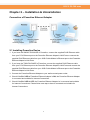
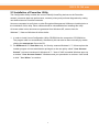
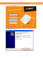
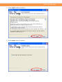
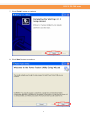
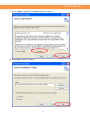
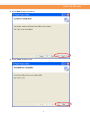
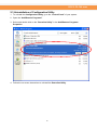
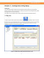
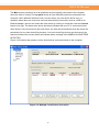
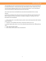
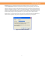
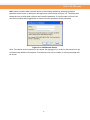
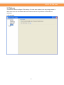
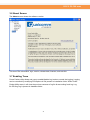
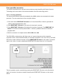
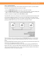
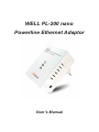
WELL PL-200 nano
Powerline Ethernet Adaptor
User’s Manual
WEEE Directive & Product Disposal
At the end of its serviceable life,
this product should not be treated as household or general waste.
It should be handed over to the applicable collection point for
the recycling of electrical and electronics equipment,
or returned to the supplier for disposal.
Table of Contents
Chapter 1 – Introduction ................................................................................................................. 1
1.1 Overview ........................................................................................................................... 1
1.2 Specification ..................................................................................................................... 1
1.3 LED Indicators .................................................................................................................. 1
1.4 Package Contents .............................................................................................................. 1
1.5 System Requirements........................................................................................................ 1
Chapter 2 – Installation & Uninstallation ....................................................................................... 2
2.1 Installing Powerline Device .............................................................................................. 2
2.2 Installation of Powerline Utility........................................................................................ 3
2.3 Uninstallation of Configuration Utility........................................................................... 10
Chapter 3 – Configuration Utility Setup ....................................................................................... 11
3.1 Map View ........................................................................................................................ 11
3.2 Detailed View.................................................................................................................. 17
3.3 Device Setup ................................................................................................................... 18
3.4 Advanced......................................................................................................................... 19
3.5 Options ............................................................................................................................ 20
3.6 About Screen ................................................................................................................... 21
3.7 Enabling Trace ................................................................................................................ 21
Chapter 4 – Reset and Network ID Setting ................................................................................... 22
4.1 Reset function ................................................................................................................. 22
4.2 Network ID function ....................................................................................................... 22
WELL PL-200 nano
Chapter 1 – Introduction
1.1 Overview
The Powerline Device operates on HomePlug AV standard, providing up to 200Mbps data speed
over the existing household power supply. This product is cost-effective, easy to create a home
network without spending time and money to run expensive CAT-5 cabling. Powerline Device is
the best solution for no-new-wire networking in the house or office.
1.2 Specification
- Standard : HomePlug Powerline Specification AV compliant
- Speed : up to 200Mbps
- Modulation : supports OFDM, 1024/256/64/16/8 QAM, QPSK, BPSK, and ROBO modulation
schemes.
- Frequency : 2 MHz ~ 30Hz
- Security : 128-bits AES encryption
- IEEE802.3 10Base-T, IEEE802.3U 100Base-TX
1.3 LED Indicators
The Powerline Ethernet Adaptor has three LEDs indicator:
Turn on when connected to AC power supply.
Turn on when detected and connected with another HomePlug
adaptor within the network.
Turn on when connected to the Ethernet card of the computer or
Ethernet Hub / Switch.
1.4 Package Contents
Make sure that you have the following items:
- Powerline Ethernet Adaptor
- RJ-45 Ethernet Network cable
- Powerline Utility CD
- Quick Installation Guide
1.5 System Requirements
- Powerline Ethernet Adaptor can support any Operation System. But the Powerline Utility can
only support Windows 2000/XP/Vista/Windows 7/Windows 8.
- Pentium III 300 MHz or above
- Powerline device
- AC power outlet
1
WELL PL-200 nano
Chapter 2 – Installation & Uninstallation
Connection of Powerline Ethernet Adapter
2.1 Installing Powerline Device
1. If you have the SINGLE PACKAGE of Powerline, connect the supplied RJ45 Ethernet cable
from your PC's Ethernet port to the Powerline Ethernet Adapter's LAN Ports or connect the
supplied RJ45 Ethernet cable from your xDSL/Cable Modem's Ethernet port to the Powerline
Ethernet Adapter's LAN Ports.
2. If you have the TWIN PACKAGE of Powerline, connect the supplied RJ45 Ethernet cable
from your PC's Ethernet port to the Powerline Ethernet Adapter's LAN Ports and connect the
supplied RJ45 Ethernet cable from your xDSL/Cable Modem's Ethernet port to the Powerline
Ethernet Adapter's LAN Ports.
3. Connect the Powerline Ethernet Adapter to your wall-mounted power outlet.
4. Check if the PLC LED of Powerline Ethernet Adapter is ON, the Powerline Ethernet Adapter
is connected and suitable for Internet Connections.
5. Check if the PLC LED is OFF, the Powerline Ethernet Adapter isn’t connected and suitable
for Internet Connections. Please follow next step to have it connected and suitable for
Internet Connections.
2
WELL PL-200 nano
2.2 Installation of Powerline Utility
The Configuration Utility enables the users to identify HomePlug devices on the Powerline
network, measures data rate performance, ensures privacy and performs diagnostics by setting
user defined secure Powerline networks.
Users are requested to verify that no other Encryption Management Utilities are installed prior to
the installation of this utility. Other utilities should be uninstalled before installing this utility.
All screen shots in this document are generated from Windows XP; screen shots for
Windows 7, Vista and Windows 8 will be similar.
1. In order to install, insert Configuration Utility CD-ROM into the computer’s CD-ROM drive.
The program shall run automatically. Alternatively this can also be done manually by double
clicking the autorun.exe file on the CD.
2. For Windows 8 / 7 / Vista User only, for Security reasons Windows 8 / 7 / Vista requires the
installer program to have administrator privileges so the new policy called " User Account
Control " has been introduced in Windows 8 / 7 / Vista. If UAC is enabled Windows pops up
a window " User Account Control " Windows need your permission to continue. User needs
to click " Yes / Allow " to continue.
3
WELL PL-200 nano
3. Please click “Power line Utility” button to continue.
4. Click “Next” button to continue.
4
WELL PL-200 nano
5. Click “I Agree” button to continue.
6. Click “Install” button to continue.
5
WELL PL-200 nano
7. Click “Finish” button to continue.
8. Click “Next” button to continue.
6
WELL PL-200 nano
9. Click “I Agree” and then click “Next” button to continue.
10. Click “Next” button to continue.
7
WELL PL-200 nano
11. Click “Next” button to continue.
12. Click “Close” button to exit.
8
WELL PL-200 nano
13. In order to start the utility, double-click the utility icon on desktop.
14. You can see your device working well. The top panel of the screen shot shows a Homeplug
device connected locally to your computer. The bottom panel shows one device connected
remotely to the computer running the utility.
9
WELL PL-200 nano
2.3 Uninstallation of Configuration Utility
1. To uninstall the Configuration Utility, go to the “Control Panel” of your system.
2. Open the “Add/Remove Programs”.
3. Select and double click on the “Powerline Utility” in the Add/Remove Programs
Properties.
4. Follow the on screen instructions to uninstall the Powerline Utility.
10
WELL PL-200 nano
Chapter 3 – Configuration Utility Setup
Introduction
The Configuration Utility enables the users to identify HomePlug devices on the powerline
network, measures data rate performance, ensures privacy and performs diagnostics by setting
user defined secure powerline networks.
The Utility will use a Graphical User Interface (GUI) with limited user selectable options.
3.1 Map View
In order to start the utility, double-click the utility icon
on desktop. Figure 3-1 shows
the main screen of the Configuration Utility. The top panel of the screen shot shows a HomePlug
AV device connected locally to the host computer. The bottom panel shows four devices
connected remotely to the computer running the utility.
Figure 3-1: Main Screen with HomePlug AV device Local
11
WELL PL-200 nano
The Main screen provides a list of all powerline devices logically connected to the computer
when the utility is running.The top panel shows all local HomePlug devices connected to the
computer’s NIC (Network Interface Card). In most cases, only one device will be seen. In
situations where there are more than one local device being connected, such as a USB or an
Ethernet adapter, the user can select the local device by clicking on it and then click the Connect
button to its right. The status area above the button indicates that your PC is connected to that
same device. Once connected to the local device, the utility will automatically scan the power line
periodically for any other HomePlug devices. If no local HomePlug devices are discovered, the
status area above the connect button will indicate with a message ‘NO HOMEPLUG ADAPTERS
DETECTED’.
Figure 3-2 illustrates the presence of two local devices connected locally to the computer.
Figure 3-2: Multiple Local Device Connection
12
WELL PL-200 nano
This tab displays the list of local devices and the list of remote devices currently associated with
the selected local device. It shows the device type, MAC address and the version string. There
are text indicators displaying which device is currently selected device, count of local devices,
count of remote devices, network type and the auto scan status.
Once all the local devices are identified the remote devices associated with the currently
selected
local device are displayed. Also along with the remote device MAC the signal strength, device
DAK (if available) and device alias name (if available) is displayed. Following are the list of
fields which are to be displayed:
1.
Device alias name: A user defined name by which a device with that particular MAC address
will be referred as.
2.
Password: The valid DAK of the device if it has been entered by the user.
3.
Quality: Signal quality shown in one of the selected formats selected in the OEM preference
editor.
4.
Rate: Signal strength in Mbps.
5.
MAC address: MAC address of the selected device.
13
WELL PL-200 nano
Password column by default is blank and ‘Enter Password’ button can be used to enter it.
To set the Password of the device (required when creating a private network), first select the
device by clicking on its name in the lower panel and then click on the Enter Password button. A
dialog box will appear as shown in Figure 3-3 to type the password. The selected device name is
shown above the password field and the password can be verified by hitting the OK button. The
Password field accepts the Device password in any case formats, with or without dashed
between them. If a device was not found, the user will be notified along with the suggestions to
resolve common problems. This process might take a few seconds to get completed.
Figure 3-3: Set Device Password
14
WELL PL-200 nano
Add button is used to add a remote device to the existing network by entering the device
password of the device. A dialog box will appear as shown below in Figure 3-4. The dialog box
allows the user to enter both a device name and the password. If a device was not found, the
user will be notified and suggestions to resolve common problems will be presented.
Figure 3-4: Add Remote Device
Note: The device must be present on the power line (plugged in) in order for the password to be
confirmed and added to the network. If the device could not be located, a warning message will
be shown.
15
WELL PL-200 nano
The Scan button is used to perform an immediate search of the HomePlug devices connected to
the Powerline network. By default, the utility automatically scans every few seconds and updates
the display screen.
16
WELL PL-200 nano
3.2 Detailed View
The PPU should have local system information and also should maintain the history of remote
devices. This information can be saved or printed. The following is the list of information
required to be stored for a remote device:
- Device alias name
- MAC address
- Password
- Rate
- Network
- Last seen
- Vendor Name
- Firmware Version
17
WELL PL-200 nano
3.3 Device Setup
All the device setup related options can be found in this view. A combobox displays the local
Devices
If the Network Name has been pre-configured on a local device to a value other than HomePlug
or HomePlugAV (e.g. the push button pairing function on AV devices), the PPU will show the
name as “Unknown Networkname”. Although a pre-configured Network Name can not be
displayed, the hidden Network Name will be used to add new devices to the local network.
1.
Set Local Device: This button will set the network name with the value in the text box in the
local device.
2.
Set Remote Device(s): This button will set the network name with the value in the text box in
the local device as well the connected remote devices.
3.
Use Default: This button will reset the value of the network name to “HomePlugAV”
4.
“Set” – Multicast: This button will update the multicast filter addresses present in the local
device configuration. PPU throws a message "This device does not support this update
multicast settings option." Firmware versions less than v4.4 in INT/AR6400 devices and less
than v5.2 in INT/AR7400 devices does not support this feature. Please note that firmware
v4.5 in (INT/AR6400) does not support this feature
18
WELL PL-200 nano
3.4 Advanced
This view contains the advanced options. All operations are with respect to selected local
devices only. A combobox displays the local devices. Following are operations supported:
1.
Upgrade firmware: To upgrade the firmware in a device click the upgrade button. Use the
browse buttons to select the firmware and PIB files.
NOTE:
The utility only supports upgrading of the local device. Remote device upgrades are
not supported. Also if the device is in “Bootloader” mode (i.e) it has MAC address as
00:b0:00:00:00:01 then the firmware cannot be upgraded.
2.
Reset Device.
3.
Reset to factory defaults.
4.
Set VLAN Tag
5.
Set TOS bits.
19
WELL PL-200 nano
3.5 Options
This view is used to configure PPU settings. For now scan options is the only thing present in
which auto scan can be checked and scan interval can be set (minimum 2 seconds and
maximum
is 60 seconds)
20
WELL PL-200 nano
3.6 About Screen
The About screen shows the software version.
This view PPU Information, logo, version, release date, licenses, and web link.
3.7 Enabling Trace
Power Packet utility allows end user to enable/disable Log levels to control the logging. Logging
can be controlled by modifying PPUOptions.ini file present in installation folder. When Power
Packet Utility starts, it will clear the previous contents of log file & start writing fresh log. Log
file PPULog.log is present in database folder.
21
WELL PL-200 nano
Chapter 4 – Reset and Network ID Setting
4.1 Reset function
Push RESET/NET.ID button can reset to the factory default settings. Be careful, when you press
the RESET/NET.ID button, please remove the Ethernet cable (RJ-45cable) first, and then press
the RESET/NET.ID button. After press the RESET/NET.ID button for 10-15 seconds and then
wait for the PWR LED light again.
4.2 Network ID function
The HomePlug AV powerline communication devices can form multiple logical networks over a
common powerline or coax medium. There are many situations when it is desirable to add new
devices to, or remove old devices from, a HomePlug AV logical network.
Push RESET/NET.ID button to accomplish using HomePlug AV Simple Connect Technology.
Network ID function trigger state conditions
“Adder state” for a device providing the NMK for an existing AVLN
“Joiner state” for a device that will join an AVLN
Pushing buttons on any two devices results in one of them becoming an “adder” and the other
one a “joiner”
22
WELL PL-200 nano
Four possible scenarios
This section describes how to add and remove devices using HomePlug AV Simple Connect
Technology and covers some of the technical details of how the technology works.
Case 1: Forming a Network
Two devices with different network membership key (NMK) values are connected to the same
powerline. The user wants them to form a logical network.
1. Press each device RESET/NET.ID button for 5-8 sec till all LEDs re-flash to generate the
random network password key first.
2. Press RESET/NET. ID button of 1st device for less than 3 seconds.
3. Press RESET/NET. ID button of 2nd device for less than 3 seconds. The RESET/NET. ID
button of 2nd device must be pressed within 1 minute, by default however the interval is
programmable.
4. Wait for connection to complete and the PLC LED will be ON.
The PWR LED on both devices will flash evenly at 1-second intervals until the operation
succeeds or fails. It will illuminate steadily on successful completion. If an error occurs, the PWR
LED on the ‘adder’ will flash unevenly until the RESET/NET.ID button on the ‘adder’ is pressed
again or the ‘joiner’ is reset by holding the RESET/NET.ID button down for 10-15 seconds.
The join operation can be cancelled by pressing the RESET/NET.ID button on the first device
again, for less than 3 seconds, instead of pressing the RESET/NET.ID button on the second
device.
23
WELL PL-200 nano
Case 2: Joining a Network
In this scenario a network exists. The user wants a new device, the ‘joiner’, to join the network.
Any device on the existing network can become the ‘adder’.
1. Press the RESET/NET.ID button on the ‘joiner’ for less than 3 seconds.
2. Press the RESET/NET.ID button on any network device for less than 3 seconds, making it the
‘adder’. You have 1 minute, by default, to press this RESET/NET.ID button.
3. Wait for connection to complete and the PLC LED will be ON.
The PWR LED on both devices will flash at 1-second intervals until the process succeeds or fails.
It will illuminate steadily on success. If an error occurs, the PWR LED on the ‘adder’ will flash
unevenly until the RESET/NET.ID button on the ‘adder’ is pressed again or the ‘joiner’ is reset by
pressing the RESET/NET.ID button for 5-8 seconds, as described in Case 3:
The join operation can be cancelled by pressing the RESET/NET.ID button on the first device
again, for less than 3 seconds, instead of pressing the RESET/NET.ID button on the second
device.
If you press RESET/NET.ID buttons on three or more devices, only the first two will respond. The
others will not. See Case 4 for a variation on this rule.
You can press the RESET/NET.ID button on the ‘adder’ before pressing the RESET/NET.ID
button on the ‘joiner’. It does not matter which is pressed first. See Case 4 for a case where the
‘adder’ may be pressed before the ‘joiner’. Once a ‘joiner’ becomes a member of the network, it
may become the ‘adder’ in the next join operation.
24
WELL PL-200 nano
Case 3: Leaving a Network
A network exists. The user wants to remove one device, the ‘leaver’, from that network, for
whatever reason. He may want to remove the device from service altogether or have it join
another logical network.
1. Press the RESET/NET.ID button on the ‘leaver’ for 5-8 seconds. The device will reset and
restart with a random NMK.
2. Wait for reset to complete and the PLC LED will be OFF.
The PWR LED on the ‘leaver’ will momentarily extinguish during reset, flash during restart then
illuminate steadily. No errors can occur.
Once the process completes, the user may disconnect the device from the medium or join it to
another logical network on the same medium, as described in either Case 1 or Case 3.
25
WELL PL-200 nano
Case 4: Join Multiple Devices to a Network
To add several new devices to an existing network, the process in Case 2 must be repeated for
each ‘joiner’. A vendor may implement a mode of operation in which an ‘adder’ device in the
network remains in the adder state for an extended period allowing additional ‘joiners’ to be
added in turn. This lets you press the ‘adder’ RESET/NET.ID button once then press each ‘joiner’
RESET/NET.ID button in turn.
If RESET/NET.ID buttons are pressed on two or more joiners, only the first one will respond. The
second will not. This makes timing important.
26