1
Acer Aspire 3935
Notebook Computer Service Guide
Service guide files and updates are available
on the Acer/CSD web site; for more
information, go to http://csd.acer.com.tw
PRINTED IN TAIWAN
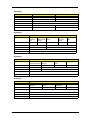
Revision History
Refer to the table below for changes made on this version of the Acer Aspire 3935 Notebook Computer
Service Guide.
Date
ii
Chapter
Updates
Acer Aspire 3935 Service Guide
Copyright
Copyright © 2009 by Acer Incorporated. All rights reserved. No part of this publication may be reproduced,
transmitted, transcribed, stored in a retrieval system, or translated into any language or computer language, in
any form or by any means, electronic, mechanical, magnetic, optical, chemical, manual or otherwise, without
the prior written permission of Acer Incorporated.
Disclaimer
The information in this guide is subject to change without notice.
Acer Incorporated makes no representations or warranties, either expressed or implied, with respect to the
contents hereof and specifically disclaims any warranties of merchantability or fitness for any particular
purpose. Any Acer Incorporated software described in this guide is sold or licensed "as is". Should the
programs prove defective following their purchase, the buyer (and not Acer Incorporated, its distributor, or its
dealer) assumes the entire cost of all necessary servicing, repair, and any incidental or consequential
damages resulting from any defect in the software.
Acer is a registered trademark of Acer Incorporated.
Other brand and product names are trademarks and/or registered trademarks of their respective holders.
Acer Aspire 3935 Service Guide
iii
Conventions
The following textual conventions are used in this service guide.
iv
SCREEN MESSAGES
Denotes actual messages that appear on screen.
NOTE
Gives additional information related to the current topic.
WARNING
Alerts you to any physical risk or system damage that might result from
doing or not doing specific actions.
CAUTION
Gives precautionary measures to avoid possible hardware or software
problems.
IMPORTANT
Reminds you to do specific actions relevant to the accomplishment of
procedures.
Acer Aspire 3935 Service Guide
Service Guide Coverage
This Service Guide provides you with all technical information relating to the BASIC CONFIGURATION
decided for our "global" product offering. To better fit local market requirements and enhance product
competitiveness, your regional office MAY have decided to extend the functionality of a machine (e.g. add-on
card, modem, or extra memory capability). These LOCALIZED FEATURES will NOT be covered in this generic
service guide. In such cases, please contact your regional offices or the responsible personnel/channel to
provide you with further technical details.
FRU Information
Please note WHEN ORDERING FRU PARTS, that you should check the most up-to-date information available
on your regional web or channel. If, for whatever reason, a part number change is made, it will not be noted in
the printed service guide. For AUTHORIZED SERVICE PROVIDERS, your office may have a DIFFERENT
part number code to those given in the FRU list of this printed service guide. You MUST use the list provided
by your regional Acer office to order FRU parts for repair and service of customer machines.
Acer Aspire 3935 Service Guide
v
vi
Acer Aspire 3935 Service Guide
Table of Contents
Chapter 1 – Features and Specifications
Features . . . . . . . . . . . . . . . . . . . . . . . . . . . . . . . . . . . . . . . . . . . . . . . . . . . . . . . . . . . .1
Hardware . . . . . . . . . . . . . . . . . . . . . . . . . . . . . . . . . . . . . . . . . . . . . . . . . . . . . . .1
Display and Camera . . . . . . . . . . . . . . . . . . . . . . . . . . . . . . . . . . . . . . . . . . . . . . .2
Keyboard and Pointing Device . . . . . . . . . . . . . . . . . . . . . . . . . . . . . . . . . . . . . . . .2
LED Indicators and Buttons . . . . . . . . . . . . . . . . . . . . . . . . . . . . . . . . . . . . . . . . . . .2
Software . . . . . . . . . . . . . . . . . . . . . . . . . . . . . . . . . . . . . . . . . . . . . . . . . . . . . . . .3
Ergonomics and Security . . . . . . . . . . . . . . . . . . . . . . . . . . . . . . . . . . . . . . . . . . . .3
Environmental Requirements . . . . . . . . . . . . . . . . . . . . . . . . . . . . . . . . . . . . . . . . .3
System Tour . . . . . . . . . . . . . . . . . . . . . . . . . . . . . . . . . . . . . . . . . . . . . . . . . . . . . . . . .4
Top View . . . . . . . . . . . . . . . . . . . . . . . . . . . . . . . . . . . . . . . . . . . . . . . . . . . . . . . .4
Close Front View . . . . . . . . . . . . . . . . . . . . . . . . . . . . . . . . . . . . . . . . . . . . . . . . . .6
Rear View . . . . . . . . . . . . . . . . . . . . . . . . . . . . . . . . . . . . . . . . . . . . . . . . . . . . . . .6
Left View . . . . . . . . . . . . . . . . . . . . . . . . . . . . . . . . . . . . . . . . . . . . . . . . . . . . . . .7
Right View . . . . . . . . . . . . . . . . . . . . . . . . . . . . . . . . . . . . . . . . . . . . . . . . . . . . . .7
Base View . . . . . . . . . . . . . . . . . . . . . . . . . . . . . . . . . . . . . . . . . . . . . . . . . . . . . .8
Specifications . . . . . . . . . . . . . . . . . . . . . . . . . . . . . . . . . . . . . . . . . . . . . . . . . . . . . . . .9
Chapter 2 – System Utilities
Phoenix SecureCore Setup Utility . . . . . . . . . . . . . . . . . . . . . . . . . . . . . . . . . . . . . . . .17
Accessing the Setup Utility . . . . . . . . . . . . . . . . . . . . . . . . . . . . . . . . . . . . . . . . . .18
Navigating through the Setup Utility . . . . . . . . . . . . . . . . . . . . . . . . . . . . . . . . . . .19
Setup Utility Menus . . . . . . . . . . . . . . . . . . . . . . . . . . . . . . . . . . . . . . . . . . . . . . .19
Chapter 3 – System Disassembly
Disassembly Tools . . . . . . . . . . . . . . . . . . . . . . . . . . . . . . . . . . . . . . . . . . . . . . . . . . .27
Stages of the Disassembly Process . . . . . . . . . . . . . . . . . . . . . . . . . . . . . . . . . . . . . . .27
Equivalent Torque Values . . . . . . . . . . . . . . . . . . . . . . . . . . . . . . . . . . . . . . . . . . . . . .27
System Screw List . . . . . . . . . . . . . . . . . . . . . . . . . . . . . . . . . . . . . . . . . . . . . . . . . . . .28
Pre-disassembly Procedure . . . . . . . . . . . . . . . . . . . . . . . . . . . . . . . . . . . . . . . . . . . . .28
External Modules Disassembly . . . . . . . . . . . . . . . . . . . . . . . . . . . . . . . . . . . . . . . . . .29
External Modules Disassembly Flowchart . . . . . . . . . . . . . . . . . . . . . . . . . . . . . . .29
Removing the Battery Pack . . . . . . . . . . . . . . . . . . . . . . . . . . . . . . . . . . . . . . . . . .30
Removing the SD Dummy Card . . . . . . . . . . . . . . . . . . . . . . . . . . . . . . . . . . . . . .30
Removing the Lower Case Cover . . . . . . . . . . . . . . . . . . . . . . . . . . . . . . . . . . . . .31
Removing the Memory Modules . . . . . . . . . . . . . . . . . . . . . . . . . . . . . . . . . . . . .32
Removing the Hard Disk Drive . . . . . . . . . . . . . . . . . . . . . . . . . . . . . . . . . . . . . . .33
Removing the WLAN Module . . . . . . . . . . . . . . . . . . . . . . . . . . . . . . . . . . . . . . .34
Removing the WWAN (3G) Module . . . . . . . . . . . . . . . . . . . . . . . . . . . . . . . . . . .35
Main Unit Disassembly 38
Main Unit Disassembly Flowchart . . . . . . . . . . . . . . . . . . . . . . . . . . . . . . . . . . . .38
Removing the Middle Cover . . . . . . . . . . . . . . . . . . . . . . . . . . . . . . . . . . . . . . . .39
Removing the Keyboard . . . . . . . . . . . . . . . . . . . . . . . . . . . . . . . . . . . . . . . . . . .39
Removing the LCD Module . . . . . . . . . . . . . . . . . . . . . . . . . . . . . . . . . . . . . . . . .40
Removing the Upper Case . . . . . . . . . . . . . . . . . . . . . . . . . . . . . . . . . . . . . . . . . .43
Removing the Speakers . . . . . . . . . . . . . . . . . . . . . . . . . . . . . . . . . . . . . . . . . . . .45
Removing the Thermal Bracket . . . . . . . . . . . . . . . . . . . . . . . . . . . . . . . . . . . . . .46
Removing the Fingerprint Reader Board . . . . . . . . . . . . . . . . . . . . . . . . . . . . . . . .47
vii
Acer Aspire 3935 Service Guide
Table of Contents
Removing the Microphone . . . . . . . . . . . . . . . . . . . . . . . . . . . . . . . . . . . . . . . . .48
Removing the Touchpad Board . . . . . . . . . . . . . . . . . . . . . . . . . . . . . . . . . . . . . .49
Removing the Cover Switch Cable . . . . . . . . . . . . . . . . . . . . . . . . . . . . . . . . . . . .49
Removing the Optical Disc Drive . . . . . . . . . . . . . . . . . . . . . . . . . . . . . . . . . . . . . .50
Removing the Mainboard . . . . . . . . . . . . . . . . . . . . . . . . . . . . . . . . . . . . . . . . . .51
Removing the Heat Sink Fan (HSF) Assembly . . . . . . . . . . . . . . . . . . . . . . . . . . . .54
Removing the Processor . . . . . . . . . . . . . . . . . . . . . . . . . . . . . . . . . . . . . . . . . . .55
Removing the I/O Board . . . . . . . . . . . . . . . . . . . . . . . . . . . . . . . . . . . . . . . . . . .56
Removing the DC-in Cable . . . . . . . . . . . . . . . . . . . . . . . . . . . . . . . . . . . . . . . . .56
LCD Module Disassembly . . . . . . . . . . . . . . . . . . . . . . . . . . . . . . . . . . . . . . . . . . . . .57
LCD Module Disassembly Flowchart . . . . . . . . . . . . . . . . . . . . . . . . . . . . . . . . . .57
Removing the LCD Bezel . . . . . . . . . . . . . . . . . . . . . . . . . . . . . . . . . . . . . . . . . .58
Removing the LCD Panel . . . . . . . . . . . . . . . . . . . . . . . . . . . . . . . . . . . . . . . . . . .59
Removing the LCD Panel Brackets . . . . . . . . . . . . . . . . . . . . . . . . . . . . . . . . . . . .61
Removing the CCD Board . . . . . . . . . . . . . . . . . . . . . . . . . . . . . . . . . . . . . . . . . .62
Chapter 4 – Troubleshooting
Clearing a BIOS Password . . . . . . . . . . . . . . . . . . . . . . . . . . . . . . . . . . . . . . . . . . . . . .63
Unlocking the Hard Drive . . . . . . . . . . . . . . . . . . . . . . . . . . . . . . . . . . . . . . . . . . . . . .64
BIOS Recovery . . . . . . . . . . . . . . . . . . . . . . . . . . . . . . . . . . . . . . . . . . . . . . . . . . . . . .64
Creating the BIOS Crisis Recovery Disk . . . . . . . . . . . . . . . . . . . . . . . . . . . . . . . . .64
Performing a BIOS Recovery . . . . . . . . . . . . . . . . . . . . . . . . . . . . . . . . . . . . . . . . .65
POST Error Indicators . . . . . . . . . . . . . . . . . . . . . . . . . . . . . . . . . . . . . . . . . . . . . . . . .65
POST Error Messages . . . . . . . . . . . . . . . . . . . . . . . . . . . . . . . . . . . . . . . . . . . . . .65
POST Beep Codes . . . . . . . . . . . . . . . . . . . . . . . . . . . . . . . . . . . . . . . . . . . . . . . . .67
BIOS Beep Codes for Boot Block in Flash ROM . . . . . . . . . . . . . . . . . . . . . . . . . . .70
Troubleshooting Procedure . . . . . . . . . . . . . . . . . . . . . . . . . . . . . . . . . . . . . . . . . . . .71
System Check Procedures . . . . . . . . . . . . . . . . . . . . . . . . . . . . . . . . . . . . . . . . . . .71
Intermittent Problems . . . . . . . . . . . . . . . . . . . . . . . . . . . . . . . . . . . . . . . . . . . . . .73
Undetermined Problems . . . . . . . . . . . . . . . . . . . . . . . . . . . . . . . . . . . . . . . . . . . .73
Online Support Information . . . . . . . . . . . . . . . . . . . . . . . . . . . . . . . . . . . . . . . . . . . .74
Chapter 5 – System Architecture
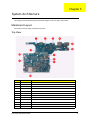
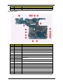
Mainboard Layout . . . . . . . . . . . . . . . . . . . . . . . . . . . . . . . . . . . . . . . . . . . . . . . . . . .75
Top View . . . . . . . . . . . . . . . . . . . . . . . . . . . . . . . . . . . . . . . . . . . . . . . . . . . . . . .75
Bottom View . . . . . . . . . . . . . . . . . . . . . . . . . . . . . . . . . . . . . . . . . . . . . . . . . . . .76
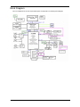
Block Diagram . . . . . . . . . . . . . . . . . . . . . . . . . . . . . . . . . . . . . . . . . . . . . . . . . . . . . .77
Chapter 6 – Field Replaceable Unit (FRU) List
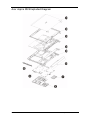
Acer Aspire 3935 Exploded Diagram . . . . . . . . . . . . . . . . . . . . . . . . . . . . . . . . . . . . .80
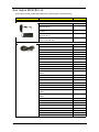
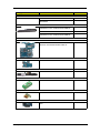
Acer Aspire 3935 FRU List . . . . . . . . . . . . . . . . . . . . . . . . . . . . . . . . . . . . . . . . . . . . .82
Appendix A – Model Definition and Configurations . . . . . . . . . . . . . . . . . . . .92
Appendix A – Test Compatible Components . . . . . . . . . . . . . . . . . . . . . . . . . .119
Index
. . . . . . . . . . . . . . . . . . . . . . . . . . . . . . . . . . . . . . . . . . . . . . . . . .123
Acer Aspire 3935 Service Guide
viii
Chapter 1
Features and Specifications
This chapter lists the features and specifications of the Acer Aspire 3935 system.
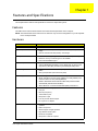
Features
This tables in this section list the features and environmental requirements of the computer.
NOTE: The features listed in this section are for reference only. The exact configuration of your PC depends
on the model purchased.
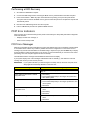
Hardware
Component
Description
Processor
Intel Core 2 Duo Mobile Processor or Intel Celeron 2 Series Processor
System chipset
•
Mobile Intel GM45 Graphics Memory Controller Hub (GMCH) - north
bridge
•
Intel I/O Controller Hub 9M (ICH9M) - south bridge
•
Two DIMM slots supporting DDR3 1066 MHz modules (PC3-8500)
•
Maximum memory of 8 GB using two 4 GB soDIMM
•
Dual channel SDRAM support
Memory
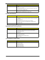
Expansion options
Media storage
Connectivity
I/O ports
Audio
Acer Aspire 3935 Service Guide
•
5-in-1 card reader slot
•
Supports MultiMediaCard (MMC), Secure Digital (SD), xD-Picture Card
(xD), Memory Stick (MS), and Memory Stick PRO (MS PRO) cards
•
1.8- or 2.5 inch SATA hard disk drive (HDD); or 1.8-in solid state drive
(SSD)
•
Slim type Super Multi optical disc drive (ODD)
•
Ethernet: Gigabit Ethernet; Wake-on-LAN ready
•
WLAN: Intel WiFi Link 5100 (512AG_MMWG or 512AN_HMWG) / Intel
Ultimate N WiFi Link 5300 (533AN_MMWG2)
•
WWAN: UMTS/HSPA at 850/1900/2100 MHz and quad-band GSM/
GPRS/EDGE (850/900/1800/1900 MHz)
•
WPAN: Bluetooth 2.0+Enhanced Data Rate (EDR) / Bluetooth 2.1
•
Acer Bio-Protection fingerprint reader
•
VGA port
•
Ethernet port (RJ-45)
•
Three USB 2.0 ports
•
Microphone-in jack
•
Line-out jack with S/PDIF support
•
DC-in jack for AC adapter
•
Dolby-optimized surround sound system with two built-in stereo
speakers
•
Built-in microphone
•
S/PDIF support for digital speakers
•
High-definition audio system
•
MS-Sound compatible
•
Microphone-in and line-out jacks
1
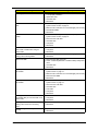
Component
Description
Power supply
•
4-cell 42.9 W 2900 mAh or 8-cell 85.8 W 5800 mAh Lithium Ion battery
pack
•
3-pin 65 W AC adapter
•
Charging period:3–3.5 hours for 0–80%,4–4.5 hours for 0–99%,4.5–5
hours for 0–100% (charge-in-use)
•
Dimension (W × D × H): 323 × 236 x 20/25.4 mm (12.8 × 9.3 × 0.8/1 in)
•
Weight (with 4 cell battery pack): 1.9 kg (4.18 lb)
Physical specifications
Display and Camera
Component
Description
Display type
•
13.3” HD LCD panel
•
Supported resolutions: 1366×768, 1280×768, 1280×720, 1024×768, and
800×600
Webcam
•
16:9 aspect ratio
•
Simultaneous multi-window viewing via Acer GridVista
•
Function control keys for manual adjustment of the display panel
brightness level
Integrated Acer Crystal Eye webcam
Keyboard and Pointing Device
Component
Description
Keyboard
•
86-/87-/91-key keyboard with embedded numeric keypad, inverted-T
cursor keys, Internet scroll key, and 12 function keys (hotkeys)
•
Multilanguage support
•
Spill-proof
•
Up/down scroll segment
•
Touchpad on/off function
•
Adjustable touchpad sensitivity function
•
Spill-resistant
Pointing device
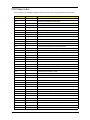
LED Indicators and Buttons
2
Component
Description
LED indicators
•
Num Lock (blue)
•
Caps Lock (blue)
•
Media activity (blue)
•
Power (blue/orange)
•
Battery (blue/orange)
Acer Aspire 3935 Service Guide
Component
Description
Buttons with LED indicator
•
Power (white)
•
Volume adjust (blue)
•
Volume mute (blue)
•
WWAN (green)
•
WLAN (orange)
•
Bluetooth (blue)
•
Backup (blue)
•
PowerSmart (green)
•
Touchpad (orange)
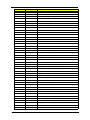
Software
Aspect
Description
Operating system support
Microsoft Genuine Windows Vista
System utilities
•
Phoenix SecureCore Setup Utility - for configuring the system hardware
and related function. Go to page 75 for more information
•
Acer Backup Management
•
ACPI 3.0 (Advanced Configuration Power Interface) standard
•
Energy Star-compliant
Power management
Ergonomics and Security
Aspect
Description
Ergonomics
•
Spill-resistant keyboard and touchpad
•
Status LED indicators allows constant monitoring of basic system functions
•
Function control keys allows convenient control of various system
operations
•
User-programmable launch button for priority applications
•
DIY HDD and memory upgrade options
•
High-capacity, rechargeable battery pack
•
ACPI-compliant power management system
•
Acer Bio-Protection fingerprint solution
•
BIOS-based user, supervisor, and HDD passwords
•
Kensington lock
Security
Environmental Requirements
Aspect
Description
Operating temperature
5 to 35 °C (41 to 95 °F)
Operating humidity
20% to 80% RH non-condensing
Acer Aspire 3935 Service Guide
3
System Tour
The pictures and tables in this section illustrate the physical outlook of the computer.
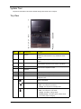
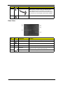
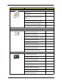
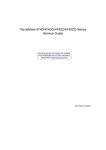
Top View
Item
Component
Function
Acer Crystal Eye
webcam
Web camera for video communication.
2
Display screen
Also called Liquid Crystal Display (LCD), displays computer
output.
3
Power button/indicator
Press to toggle the computer on and off. The button lights up
white when the computer is in DC mode or is turned on.
4
Volume mute
Adjusts or mute the sound volume. The buttons light up blue
when volume is adjusted or muted.
1
Icon
Volume control buttons/
indicators
5
Caps Lock indicator
Lights up blue when Caps Lock is activated.
6
Keyboard
For entering data into your computer.
7
Touchpad
Touch-sensitive pointing device which functions like a
computer mouse.
8
Media activity indicator
Lights up blue when there is hard drive, optical drive, or
memory card activity.
Power indicator
Indicates the computer’s power status.
Battery indicator
4
NOTE: The webcam feature is only available for certain
models.
•
Blue - The computer is powered on.
•
Orange - The computer is in standby mode.
Indicates the computer's battery status.
•
Blue - The computer is in AC mode.
•
Orange - The battery is being charge.
•
Flashing orange - The battery power is below critical
level; battery requires charging.
Acer Aspire 3935 Service Guide
Item
Icon
9
Component
Function
Click buttons
The left and right buttons function like the left and right mouse
buttons.
The center button is the Acer Bio-Protection fingerprint
reader. It supports the FingerNav 4-way control function.
NOTE: The Acer Bio-Protection fingerprint reader feature is
only available for certain models.
10
Microphone
Built-in internal microphone for sound recording.
11
Palmrest
Comfortable support area for your hands when you use the
computer.
12
Touchpad button/
indicator
Toggles the touchpad on and off. The button lights up orange
when the touchpad is enabled.
3G WWAN
communication button/
indicator
Enables/disables the 3G Wireless Wide Area Network
(WWAN) function. The button lights up green when the
WWAN function is enabled.
13
3G
NOTE: The 3G feature is only available for certain models.
WLAN communication
button/indicator
Enables/disables the Wireless LAN (WLAN) function. The
button lights up orange when the WLAN function is enabled.
Bluetooth
communication button/
indicator
Enables/disables the Bluetooth function. The button lights up
blue when the Bluetooth function is enabled.
NOTE: The Bluetooth feature is only available for certain
models.
Backup button/indicator
Press to launch the Acer Backup Management utility and
perform a data backup. The button lights up blue during the
backup process.
14
Num Lock indicator
Lights up blue when Num Lock is activated.
15
Acer PowerSmart
button/indicator
Press to put your computer into power-saving mode. The
button lights up green when this happens.
16
Speakers
Left and right speakers deliver stereo audio output.
Acer Aspire 3935 Service Guide
5
Hotkeys
The computer employs hotkeys or key combinations to access most of the computer's controls like screen
brightness and volume output.
To activate hotkeys, press and hold the <Fn> key before pressing the other key in the hotkey combination.
Hotkey
Icon
Function
Description
<Fn> + <F2>
System property
Opens the System Property panel for displaying
system information.
<Fn> + <F4>
Sleep
Puts the computer in Sleep mode.
<Fn> + <F5>
Display toggle
Switches display output between the display screen,
an external monitor (if connected) and both.
<Fn> + <F6>
Screen blank
Turns the display screen backlight off to save power.
Press any key to turn it back on.
<Fn> + <F8>
Speaker toggle
Turns the speakers on and off.
Volume up
Increases the sound volume.
Volume down
Decreases the sound volume.
Brightness up
Increases the screen brightness.
Brightness down
Decreases the screen brightness.
<Fn> + <
>
<Fn> + <
>
<Fn> + <
>
<Fn> + <
>
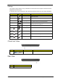
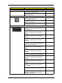
Close Front View
Item
Icon
1
Component
Function
5-in-1 card reader
Supports MMC, SD, xD, MS, and MS PRO cards.
Rear View
6
Item
Component
1
Battery pack
Acer Aspire 3935 Service Guide
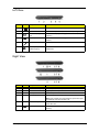
Left View
Item
Icon
Component
Function
1
DC-in jack
Connects to the AC adapter.
2
Ventilation slots
Enable the computer to stay cool, even after prolonged use.
3
External display (VGA)
port
Connects to a display device (e.g., external monitor, LCD
projector).
4
USB 2.0 ports
Connect to USB 2.0 devices (e.g., USB mouse, USB
camera).
5
Microphone-in jack
Accepts inputs from external microphones.
Line-out jack (with
S/PDIF support)
Connects to audio line-out devices such as speakers, or
headphones.
6
SPDIF
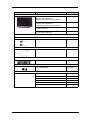
Right View
Item
Component
Function
1
Icon
Optical disc drive (ODD)
Internal optical drive; accepts CDs or DVDs.
2
ODD access indicator
Lights up when the optical drive is active.
3
ODD eject button
Ejects the optical disc from the drive.
4
Emergency eject hole
Ejects the optical drive tray when the computer is turned off.
Note: Insert a paper clip to the emergency eject hole to eject
the ODD tray when the computer is off.
5
2.5-in HDD bay
In certain models, houses a second hard disk instead of an
optical disc drive.
6
USB 2.0 port
Connect to USB 2.0 devices (e.g., USB mouse, USB
camera).
Acer Aspire 3935 Service Guide
7
Item
Icon
Component
Function
7
Kensington lock notch
Connects to a Kensington-compatible computer security lock.
Note: Wrap the computer security lock cable around an
immovable object such as a fixed table or the handle of a
locked drawer. Insert the lock into the notch and turn the key
to secure the lock. Some keyless models are also available.
3
Ethernet port (RJ-45)
Connects to an Ethernet 10/100/1000-based network
Component
Function
1
Battery bay
Houses the computer's battery pack.
2
Battery lock
Locks the battery pack in position.
3
Memory compartment
Houses the computer's memory modules.
4
HDD bay
Houses the computer's hard disk.
5
Ventilation slots and
cooling fan
Enable the computer to stay cool, even after prolonged use.
Note: Do not cover or obstruct the fan opening.
6
Battery release latch
Releases the battery pack for removal.
Base View
Item
8
Icon
Acer Aspire 3935 Service Guide
Specifications
Processor
Item
Processors Type
Type
Intel Core 2 Duo Mobile Processor
Processor number
P7350
P7450
P8400
P8600
P8700
P9500
CPU speed
2.0 GHz
2.13 GHz
2.26 GHz
2.40 GHz
2.53 GHz
2.53 GHz
Bus speed
1066 MHz
L2 cache
3 MB
Package type
Micro-FCPGA
Core stepping
M0
Thermal design power
25W
6 MB
R0
C0
System Chipsets
Item
Specification
North bridge
Mobile Intel GM45 Express Chipset
South bridge
82801IBM I/O Controller Hub (ICH9M)
System Controllers
Item
Specification
Hard drive
Integrated in the ICH9M
Memory
Integrated in the Mobile Intel GM45 Express Chipset
Video
Integrated in the Mobile Intel GM45 Express Chipset
VGA memory
Intel UMA
Audio
Realtek ALC272 4-Channel High-definition Audio Codec
Wireless LAN
Intel WiFi Link 5100 (512AG_MMWG or 512AN_HMWG) / Intel Ultimate N WiFi Link 5300
(533AN_MMWG2)
Antenna
WNC WiMax/WiFi PIFA
WWAN (3G)
Option GTM382 E High-speed PCI Express MiniCard / Qualcomm UNDP-1 (Gobi)
Wireless Solution
Ethernet
Broadcom NetLink BCM5784 Gigabit Ethernet Controller with PCI Express
Modem
External USB Lite + LSI modem
Bluetooth
Broadcom BCM2046 Single-Chip Bluetooth EDR HCI Solution / Broadcom Blutonium
BCM2045 Advanced Single-Chip Bluetooth Solution
Keyboard
Winbond WPCE773LAODG
Card reader
Realtek RTS5158E
Fingerprint reader
Validity VFS201 Fingerprint Sensor
CardBus
Richtek RTS5159-GR
Video
Item
Specification
Video controller
Integrated in the Mobile Intel GM45 Express Chipset
FSB speed
667 MHz / 800 MHz / 1066 MHz
Dual Independent Display support
Yes
Graphics output
LVDS, SDVO, TV Out, CRT, DVI, HDMI, DisplayPort
Acer Aspire 3935 Service Guide
9
Audio
Item
Specification
Audio controller
Realtek ALC272 4-Channel High-definition Audio Codec
Codec features
Microsoft WLP 3.10-compliant, WaveRT-based audio function driver for Windows Vista
Audio features
High-definition audio system, MS-Sound compatible, built-in stereo speakers;
microphone-in and line-out jacks
WLAN
Item
Specification
Model
Intel WiFi Link
512AG_MMW
Intel WiFi Link
512AN_HMW
Intel Ultimate N WiFi Link
533AN_MMWG
Connector interface
Mini Card form factor, based on PCIe electrical interface
IEEE WLAN standard
802.11a/b/g
Radio on/off control5
Supported in both hardware and software
Dimensions (H x W x D)
2.0 × 1.18 × 0.13 in (50.95 × 30 × 3.30 mm)
Weight
7.0 g
802.11a/b/g and Draft-N
802.11a/b/g and Draft-N
WWAN
Item
Specification
Model
Option GTM382 E
Connector interface
Mini Card form factor, based on PCIe electrical interface
Supported protocols
W-CDMA (HSDPA and HSUPA), GSM/
EDGE, 3G
W-CDMA (HSDPA and HSUPA), GSM/
EDGE, CDMA2000 1x, 1x EV-DO,
GPS function
No
Yes
Radio on/off control5
Supported in both hardware and software
Qualcomm UNDP-1 (Gobi)
Ethernet
Item
Specification
Ethernet controller
Broadcom NetLink BCM5784 Gigabit Ethernet Controller with PCI Express
LAN protocol
10/100/1000 Mbps
LAN connector type
RJ-45
Features
Onboard Fast Ethernet, Wake on LAN ready
Bluetooth
10
Item
Specification
Model
Broadcom Blutonium BCM2045
Broadcom BCM2046
Version
Bluetooth 2.0 (backward compatible with
1.1, 1.2)
Bluetooth 2.1 (backward compatible with
2.0, 1.1, 1.2)
EDR support
Yes
Practical data rate
2.1 Mbit/s
Acer Aspire 3935 Service Guide
Keyboard
Item
Specification
Keyboard controller
Winbond WPCE773LAODG
Brand
Darfon
Features
•
86-/87-/91-key keyboard with embedded numeric keypad, inverted-T cursor keys,
Internet scroll key, and 12 function keys (hotkeys)
•
Multilanguage support
•
Spill-proof
Fingerprint Reader
Item
Specification
Model
Validity VFS201 Fingerprint Sensor
Sensor packaging
Kapton Chip-On-Flex (COF)
Active imaging size
10 mm (200 pixel) wide image
Scanner resolution
20 pixels/mm (508 DPI) with 256 levels of grayscale at 8 bits per pixel
Interface
USB 1.1 and 2.0 full speed compliant
Operating voltage
3.3 V
RoHS compliant
Yes
Card Reader
Item
Specification
Card reader controller
Realtek RTS5158E
Card compatibility
MMC, SD, xD, MS, and MS PRO
Memory
System Memory
Item
Specification
Memory controller
Integrated in the Mobile Intel GM45 Express Chipset
Number of DIMM slot
2
Maximum memory size
8 GB using two 4 GB SO-DIMMs
DIMM speed
1066 MHz modules (PC3-8500)
DIMM type
204-pin SO-DIMM
Memory module combinations
You can install memory modules in any combination as long as they match
the above specifications.
Acer Aspire 3935 Service Guide
11
Memory Module
Item
Specification
Brand
Elpida
Micron
Samsung
Part name
EBJ11UE6BAU0-AE-E
MT8JSF12864HY-1G1
M471B2874DZ1-CF8, M471B2873EH1-CF8
Density
1 GB
Data rate
1066 MHz
RoHS
compliant
Yes
Brand
Elpida
Hynix
Micron
Samsung
Part name
EBJ21UE8BAU0-AE-E
HMT125S6AFP8C-G7
MT16JSF25664HY1G1D1.
M471B5673DZ1-CF8
M471B5673EH1-CF8
Density
2 GB
Data rate
1066 MHz
RoHS
compliant
Yes
Hard Disk Drive
SATA Hard Drives
60-and 80-GB HDD
Item
Specification
Product
12
Samsung Spinpoint N3C
Toshiba MKxx17GSG Series
Model
HS06VHF
HS08VHF
MK8017GSG
Capacity (GB)
60
80
80
Interface
SATA 1.5
Form factor
1.8 inch
Sector size (bytes)
512
Data buffer (MB)
16
8
Rotational speed (RPM)
5400
5400
Latency average (ms)
8.3
5.55
Interface transfer rate (Gbps)
1.5
1.5
Seek time, typical (ms)
14
15
Shock, operating
600 G/2ms
500 G/2ms
Temperature, operating
0 to 60 °C
5 to 55 °C
Height (mm)
5.0
8.0
Dimension (W x D, mm)
78.5 x 54.0
78.5 x 54.0
Weight (g)
52
60
Acer Aspire 3935 Service Guide
120-GB HDD
Item
Specification
Product
Samsung Spinpoint N3C
Toshiba MKxx29GSG Series
Model
HS12VJF
MK1229GSG
Interface
SATA 1.5
Form factor
1.8 inch
Sector size (bytes)
512
512
Rotational speed (RPM)
5400
5400
160-GB HDD
Item
Specification
Product
Samsung
Spinpoint
N3C
Toshiba
HGST Travelstar
MKxx29GSG 5K320
Series
Model
HS16VJF
MK1629GSG HTS543216L9A300 ST9160310AS
Interface
SATA 1.5
SATA 3.0
Form factor
1.8 inch
2.5-inch
Sector size (bytes)
512
Rotational speed (RPM)
5400
Seagate
Momentus
5400.5
WD Scorpio
Blue
WD1600BEVT
250-GB HDD
Item
Specification
Product
Toshiba
Hitachi Travelstar
MKxx29GSG Series 5K500.B
Seagate Momentus
5400.6
WD Scorpio Blue
Model
MK2529GSG
HTS545025B9A300
ST9250315AS
WD2500BEVT
Interface
SATA 1.5
SATA 3.0
Form factor
1.8 inch
2.5 inch
Sector size (bytes)
512
Rotational speed (RPM)
5400
320-GB HDD
Item
Specification
Product
Hitachi Travelstar
5K500.B
Seagate Momentus
5400.5
Toshiba
MKxx55GSX
WD Scorpio Blue
Model
HTS545032B9A300
ST9320320AS
MK3255GSX
WD3200BEVT
Form factor
2.5 inch
Interface
SATA 3.0
Sector size (bytes)
512
Rotational speed (RPM)
5400
Acer Aspire 3935 Service Guide
13
500-GB HDD
Item
Specification
Product
Hitachi Travelstar 5K500.B
Seagate Momentus 5400.6
WD Scorpio Blue
Model
HTS545050B9A300
ST9500325AS
WD5000BEVT
Form factor
2.5 inch
Interface
SATA 3.0
Sector size (bytes)
512
Rotational speed (RPM)
5400
Solid State Drive
Item
Specification
Model
Samsung
64GB MLC
SSD
Intel X18-M Mainstream
SATA SSD –
SSDSA1MH080G1
Samsung
128GB MLC
SSD
Intel X18-M Mainstream
SATA SSD –
SSDSA1MH160G1
Capacity (GB)
64
80
128
160
Form factor
1.8 inch
Interface
SATA 3.0
Interface transfer rate
300 MB/s
S.M.A.R.T support
Yes
Optical Disc Drive
Item
Specification
Brand
HLDS
Model
GU10N
Drive type
Super Multi Slim DVD Rewriter
GS20N
Drive-loading mechanism
Tray
Write/read speed
Tray height (mm))
Panasonic
TSST
UJ-867
TS-U633A
TS-D633A
Slot
Slot
Tray
Slot
8x
8x
8x
8x
8x
9.5
9.5
9.5
9.5
9.5
LCD Panel
14
Item
Specification
Brand
AUO
LPL
Model
B133XW01
LP133WH2
Screen size (diagonal, inch)
13.3
13.3
Type
Wide XGA
Wide XGA
Backlight
LED
LED
Contrast ratio
500:1
500:1
Response time (ms)
8
16
Optical coating
Anti-glare
Anti-glare
Interface
LVDS
Acer Aspire 3935 Service Guide
Webcam
Item
Specification
Brand
Suyin
Model
Camellia
Resolution
0.3M
Lens
2G
DV capability
Yes
AC Adapter
Item
Specification
Brand
Delta
Hipro
Lite-On
Model
SADP-65KB DFJ
SADP-65KB B FJG
SADP-65KB B FJA
HP-OK065B13
PA-1650-02AC
Output rating
19.5 V
19.5 V
19 V
Output power
65 W
65 W
65 W
Battery Pack
Item
Specification
Brand
Panasonic
Sanyo
Capacity
2900 mAh
5800 mAh
2800 mAh
5600 mAh
Pack capacity
4 cells, 2.0 mAh
8 cells, 2.0 mAh
4 cells, 2.0 mAh
8 cells, 2.0 mAh
Type
Lithium-ion, 4S1P
Lithium-ion, 4S2P
Lithium-ion, 4S1P
Lithium-ion, 4S2P
Power Management
Power status
ACPI mode
G3
•
Mechanical Off - All devices in the system are turned off completely. No electrical current is
running through the system. Except for the real-time clock, power consumption is zero. The
machine can be worked on without damaging the hardware or endangering service
personnel. –
G2 (S5)
•
Soft Off - The computer consumes a minimal amount of power. No user mode or system
mode code is run. It is not safe to disassemble the machine in this state.
G1
•
Sleeping - The computer consumes a small amount of power, user mode threads are not
being executed, and the system “appears” to be off (from the end user’s perspective, the
display is off, and so on). It is not safe to disassemble the machine in this state.
G0 (S0)
•
Working - The system dispatches user mode (application) threads and they execute. In this
state, peripheral devices are having their power state changed dynamically. The user can
select, through some UI, various performance/power characteristics of the system to have
the software optimize for performance or battery life. The system responds to external events
in real time. It is not safe to disassemble the machine in this state.
BIOS Setup and Antivirus
Item
Specification
Setup utility
Phoenix SecureCore Setup Utility
Antivirus
McAfee
Acer Aspire 3935 Service Guide
15
16
Acer Aspire 3935 Service Guide
Chapter 2
System Utilities
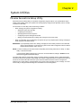
Phoenix SecureCore Setup Utility
Phoenix SecureCore Setup Utility is a hardware configuration program built into your system's Basic Input/
Output System (BIOS). Since most systems are already properly configured and optimized, there is normally
no need to run this utility.
You will need to run this utility under the following conditions:
•
When changing the system configuration including:
•
•
Setting the system time and date
•
Configuring the hard drives
•
Specifying the boot device sequence
•
Configuring the power management modes
•
Setting up system passwords or making other changes to the security setup
When a configuration error is detected by the system and you are prompted ("Run Setup" message) to
make changes to the BIOS settings.
IMPORTANT: If you repeatedly receive “Run Setup” messages, the RTC battery located on the mainboard
(RTC1) may be defective. In this case, the system cannot retain configuration values in CMOS.
Replace the RTC battery with a new one.
NOTE: For ease of reading, Phoenix SecureCore Setup Utility will be simply referred to as “Setup” or “Setup
Utility” in this Service Guide.
In the descriptive tables following each of the menu screen illustrations, settings in boldface are the
default and suggested parameter settings.
The Setup Utility loads the configuration values in a battery-backed nonvolatile memory called CMOS RAM.
This memory area is not part of the system RAM, which allows configuration data to be retained when power is
turned off. The values take effect when the system is booted. POST uses these values to configure the
hardware. If the values and the actual hardware do not agree, POST generates an error message. You must
run this utility to change the BIOS settings from the default or current configuration.
Acer Aspire 3935 Service Guide
17
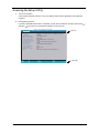
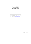
Accessing the Setup Utility
1.
Turn on the computer.
If the computer is already turned on, save your data and close all open applications, then restart the
computer.
2.
During POST, press F2.
If you fail to press F2 before POST is completed, you will need to restart the computer. Use the left (
and right ( ) arrow keys to move between selections on the menu bar.
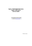
Information
Main
Phoenix SecureCore(tm) Setup Utility
Security
Boot
Exit
C P U Ty p e :
CPU Speed:
IDE0 Model Name:
IDE0 Serial Number:
ATA P I M o d e l N a m e :
S y s t e m B I O S Ve r s i o n :
V G A B I O S Ve r s i o n :
K B C Ve r s i o n :
Serial Number:
A s s e t Ta g N u m b e r :
Product Name:
Manufacturer Name:
UUID:
F1 Help
Esc Exit
18
Select Item
Select Menu
)
Menu bar
Intel (R) Core (TM)2 Duo CPU T6400 @ 2.00 GHz
2.00GHz
XXXXXXXXXXX-(XX)
XXXXXXXX
XXXXXXXXXXX-XXX XX-XXXX-(XX)
VX.XX
XX-XXX XXXXXX.XXX.XXX.XXX.XXXXXX
XX.XX
XXXXXXXXXXXXXXXXXXXXXXX
None
Aspire 5738
Acer
XXXxXxXX-xXxX-XXxx-xXXx-xXXxXXxXxxXX
-/+
Enter
C h a n g e Va l u e s
Select
Sub-Menu
F9
F10
Setup Defaults
Save and Exit
Legend bar
Acer Aspire 3935 Service Guide
Navigating through the Setup Utility
Use the keys listed in the legend bar on the bottom of the Setup screen to work your way through the various
menu and submenu screens of the Setup Utility. The table below lists these legend keys and their respective
functions.
Key
Function
and
and
To move between selections on the menu bar.
To move the cursor to the field you want.The currently selected field will be highlighted. The
right side of each menu screen displays a field help panel—Item Specific Help panel. This
panel displays the help text for the currently selected field. It updates as you move the cursor to
each field.
F5 and F6
To select a value for the currently selected field (only if it is user-configurable). Press these
keys repeatedly to display all possible entries. A parameter that is enclosed in square brackets
[ ] is user-configurable. Grayed-out parameters are not user-configurable for one of the
following reasons:
The field value is auto-configured or auto-detected.·
The field value is informational only.
The field is password-protected.
Enter
To select a field value (a pop-up menu displays) or submenu screen.
Indicates a submenu field. To view a submenu screen, use the
cursor to the submenu you want, then press Enter.
and
keys to move the
Esc
If you press this key:
On one of the primary menu screens, the Exit menu displays.
On a submenu screen, the previous screen displays.
When you are making selections from a pop-up menu, closes the pop-up without making a
selection.
F1 or Alt-H
To bring up the General Help window. The General Help window describes other Setup
navigation keys that are not displayed on the legend bar.
F9
Press to load default system values.
F10
Press to save changes and close the Setup Utility.
Setup Utility Menus
The Setup Utility has five menus for configuring the various system functions. These include:
•
Information
•
Main
•
Security
•
Boot
•
Exit
NOTE: The screenshots used in this section are for illustration only. The values displayed may not be the
same as those in your computer.
Acer Aspire 3935 Service Guide
19
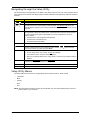
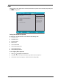
Information
The Information menu screen displays a summary of your computer hardware information. These information
are necessary for troubleshooting and may be required when asking for technical support.
Information
Main
Phoenix SecureCore(tm) Setup Utility
Security
Boot
Exit
C P U Ty p e :
CPU Speed:
IDE0 Model Name:
IDE0 Serial Number:
ATA P I M o d e l N a m e :
S y s t e m B I O S Ve r s i o n :
V G A B I O S Ve r s i o n :
K B C Ve r s i o n :
Serial Number:
A s s e t Ta g N u m b e r :
Product Name:
Manufacturer Name:
UUID:
F1 Help
Esc Exit
Select Item
Select Menu
Intel (R) Core (TM)2 Duo CPU T6400 @ 2.00 GHz
2.00GHz
XXXXXXXXXXX-(XX)
XXXXXXXX
XXXXXXXXXXX-XXX XX-XXXX-(XX)
VX.XX
XX-XXX XXXXXX.XXX.XXX.XXX.XXXXXX
XX.XX
XXXXXXXXXXXXXXXXXXXXXXX
None
Aspire 5738
Acer
XXXxXxXX-xXxX-XXxx-xXXx-xXXxXXxXxxXX
-/+
Enter
C h a n g e Va l u e s
Select
Sub-Menu
F9
F10
Setup Defaults
Save and Exit
The following table describes the information displayed in the Information menu screen.
20
Field
Description
CPU Type
Displays the processor model.
CPU Speed
Displays the processor speed.
IDE0 Model Name
Displays the model name of the hard drive installed on the primary IDE master.
IDE0 Serial Number
Displays the serial number of the hard drive installed on the primary IDE master.
IDE1 Model Name
Displays the model name of the hard drive installed on the secondary IDE master.
IDE1 Serial Number
Displays the serial number of the hard drive installed on the secondary IDE master.
ATAPI Model Name
Displays the model name of the optical disc drive installed in the system.
System BIOS Version
Displays the current system BIOS version.
VGA BIOS Version
Displays the current VGA BIOS version.
KBC Version
Displays the keyboard controller version.
Serial Number
Displays the system serial number.
Asset Tag Number
Displays the system asset tag number
Product Name
Displays the official model name of the computer.
Manufacturer Name
Displays the manufacturer of the computer.
UUID
Displays your computer’s UUID (universally unique identifier). UUID is an identifier
standard used in software construction, standardized by the Open Software
Foundation (OSF) as part of the Distributed Computing Environment (DCE).
Acer Aspire 3935 Service Guide
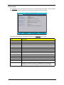
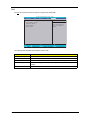
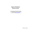
Main
The Main menu screen allows you to configure the basic system settings.
Information
Main
Phoenix SecureCore(tm) Setup Utility
Security
Exit
Boot
Item Specific Help
S y s t e m Ti m e :
System Date:
[10:10:10]
[03/05/2009]
System Memory:
Extended Memory:
Vi d e o M e m o r y :
632 KB
4093 MB
512 MB
Quiet Boot:
Network Boot:
F12 Boot Menu:
D2D Recovery:
S ATA M o d e
[Enabled]
[Enabled]
[Disabled]
[Enabled]
[AHCI]
F1 Help
Esc Exit
Select Item
Select Menu
-/+
Enter
< Ta b > , < S h i f t - Ta b > , o r
<Enter> selects field.
C h a n g e Va l u e s
Select
Sub-Menu
F9
F10
Setup Defaults
Save and Exit
The following table describes the parameters in this screen.
Field
Description
Value
System Time
Sets the system time.
HH:MM:SS
(hour:minute:second)
System Date
Sets the system date.
MM/DD/YYYY
(month/day/year)
System Memory
Displays the size of system memory detected during boot-up.
Extended Memory
Displays the size of extended memory detected during boot-up. Extended memory = Total
memory –1MB
Video Memory
Displays the size of video memory detected during boot-up.
Quiet Boot
Enables or disables the Quiet Boot function.
When enabled, BIOS setup is in graphical mode and displays
only an identification logo during POST and while booting. After
booting, the screen displays the operating system prompt (such
as DOS) or logo (such as Windows 95). If any error occurs while
booting, the system automatically switches to text mode.
When disabled, BIOS setup is in the conventional text mode
where you see the system initialization details on the screen.
Disabled
Enabled
Network Boot
When enabled, a remote host with appropriate boot image can
boot this computer. (only works with an Ethernet device.)
Disabled
Enabled
F12 Boot Menu
Enables or disables the Boot menu during POST.
Disabled
Enabled
D2D Recovery
Enables or disables D2D Recovery function. This function
allows the user to create a hidden partition on the hard drive to
store the operation system. User can then use this partition to
restore the system to factory defaults.
Disabled
Enabled
Acer Aspire 3935 Service Guide
21
Field
Description
Value
SATA Mode
Select the SATA controller operating mode.
When set to AHCI (Advanced Host Controller Interface), the
SATA controller enables its AHCI and RAID features when the
computer boots up.
When set to IDE, the SATA controller disables its AHCI and
RAID functions when the computer boots up.
AHCI
IDE
NOTE: If you do not intend to use the AHCI or RAID features set
this parameter to IDE to speed up the boot-up time.
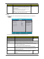
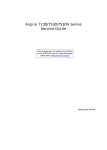
Security
The Security menu screen contains parameters that help safeguard and protect your computer from
unauthorized use.
Information
Main
Phoenix SecureCore(tm) Setup Utility
Security
Boot
Exit
Item Specific Help
Supervisor Password is:
User Password is:
HDD Password is:
Clear
Clear
Clear
Set Supervisor Password
Set User Password
Set HDD Password
[Enter]
[Enter]
[Enter]
Password on Boot:
[Disabled]
F1 Help
Esc Exit
Select Item
Select Menu
-/+
Enter
Supervisor Password
controls access of the
w h o l e s e t u p u t i l i t y.
It can be used to boot
up when Password on
boot is enabled.
C h a n g e Va l u e s
Select
Sub-Menu
F9
F10
Setup Defaults
Save and Exit
The following table describes the parameters in the Security menu screen.
22
Field
Description
Value
Supervisor Password is
Displays the supervisor password status.
User Password is
Displays the user password status.
Clear
Set
HDD Password is
Displays the HDD password status.
Set Supervisor
Password
Press Enter to configure the supervisor password. When set, this password will
allow the user to access and change all settings in the Setup Utility.
Set User Password
Press Enter to configure the user password. When set, this password will restrict a
user’s access to the Setup menus. Only the following menus will be accessible:
•
System Time and System Date
•
All Exit menu options excluding Load Setup Defaults
A supervisor password must first be set before creating this user password.
Set HDD Password
Press Enter to configure the HDD password. When set, this password will restrict a
user’s access to the hard disk drive. It will be required during boot-up or when
waking from hibernation mode.
Password on Boot
Referred to as power-on password. When enabled, the user or
supervisor password will be required to boot up the system. A
supervisor password must first be set before creating this
password.
Disabled
Enabled
Acer Aspire 3935 Service Guide
Setting a system password
Note the following before you define a system password:
•
The maximum length of password contains 8 alphanumeric characters—A - Z, 0 - 9, and ‘;’
(for French keyboard).
•
System passwords are case-insensitive.
•
When you are prompted to enter a password, you have three tries before the system halts. Do not forget
your password. If you forget your password, you may have to return your computer to your dealer to reset
it.
To set a system password:
1.
Select a password parameter, then press Enter.
The password box appears.
2.
Type a password then press Enter.
IMPORTANT: Be very careful when typing your password because the characters do not appear on the
screen. Only shaded blocks representing each typed character are visible.
3.
Retype the password to verify the first entry, then press Enter.
You will be prompted to save the new password.
4.
Press Enter.
5.
Press F10 to save the password and close the Setup Utility.
To change a system password:
1.
Select a password parameter, then press Enter.
The password box appears.
2.
Type the original password, then press Enter.
3.
Type a new password, then press Enter.
Acer Aspire 3935 Service Guide
23
4.
Retype the new password to verify the first entry, then press Enter.
You will be prompted to save the new password.
5.
Press Enter.
6.
Press F10 to save the password and close the Setup Utility.
To remove a system password:
1.
Select a password parameter, then press Enter.
The password box appears.
2.
Type the original password, then press Enter.
3.
Press Enter twice without entering anything in the new and confirm password fields.
You will be prompted to confirm the password removal.
4.
Press Enter.
5.
Press F10 to save the changes you made and close the Setup Utility.
Resetting a system password:
If you have forgotten the user password, the computer will continue to function normally but you will have
limited access to the Setup Utility.
If you have enabled the Password on Boot field and you forget the supervisor password, you will not be able to
boot up the computer. The same thing applies if you forget the HDD password.
To clear a lost BIOS password (user or supervisor password) you need to short the G26 hardware gap located
near the HDD connector (SATA1). Go to page 63 for instructions.
To regain access to your computer if you lose the HDD password, you need to generate a master password
and unlock your hard drive. Go to page 64 for instructions.
24
Acer Aspire 3935 Service Guide
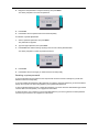
Boot
The Boot menu screen allows users to set the preferred drive sequence in which the Setup Utility attempts to
boot the operating system.
Information
Main
Phoenix SecureCore(tm) Setup Utility
Security
Boot
Exit
Item Specific Help
Boot priority order:
1:
2:
3:
4:
5:
6:
7:
IDE0: XXXXXXXXXXX-(XX)
CD/DVD: XXXXXXXXXXX-XXXXX-(X
Network Boot: XXXXXXXXXXXXXXXX
USB HDD:
USB FDD:
USB Key:
USB CD/DVD ROM:
F1 Help
Esc Exit
Select Item
Select Menu
-/+
Enter
C h a n g e Va l u e s
Select
Sub-Menu
U s e < > o r < > to
select a device, then
press <F6> to move it
up the list, or <F5>
to move it down the
list. Press <Esc> to
escape the menu.
F9
F10
Setup Defaults
Save and Exit
Setting the boot drive sequence
By default, the computer searches for boot devices in the following order:
1.
Hard disk drive 1
2.
Hard disk drive 2
3.
Optical disc drive
4.
Network boot
5.
External USB HDD
6.
External USB floppy drive
7.
External USB keyboard
8.
External USB optical drive
To set the boot drive sequence:
1.
Press
or
to highlight a bootable device.
2.
Press F5 or F6 to move the selected device up or down the boot sequence.
3.
Press F10 to save the changes you made and close the Setup Utility.
Acer Aspire 3935 Service Guide
25
Exit
The Exit menu screen lists the exit options to quit from the Setup Utility.
Information
Main
Phoenix SecureCore(tm) Setup Utility
Security
Exit
Boot
Item Specific Help
Exit Saving Changes
Exit Discarding Changes
Load Setup Defaults
Discard Changes
Save Changes
F1 Help
Esc Exit
Select Item
Select Menu
Exit System Setup and
save your changes to
CMOS.
-/+
Enter
C h a n g e Va l u e s
Select
Sub-Menu
F9
F10
Setup Defaults
Save and Exit
The following table describes the parameters in this screen.
26
Field
Description
Exit Saving Changes
Saves changes made and closes the Setup Utility. Keyboard shortcut: F10·
Exit Discarding Changes
Discards changes made and closes the Setup Utility.
Load Setup Defaults
Loads the factory-default settings for all Setup parameters. Keyboard shortcut: F9
Discard Changes
Discards all changes made to the Setup Utility and loads previous configuration
settings.
Save Changes
Saves all changes made to the Setup Utility.
Acer Aspire 3935 Service Guide
Chapter 3
System Disassembly
This chapter provides step-by-step instructions on how to disassemble the computer for maintenance and
troubleshooting purposes.
Disassembly Tools
In performing the disassembly process, you will need the following tools:
Wrist-grounding strap and conductive mat for preventing electrostatic discharge
Philips screwdriver
Flat screwdriver
Plastic flat-blade screwdriver
Plastic tweezers
Stages of the Disassembly Process
The disassembly process is divided into three stages:
1.
External modules disassembly
2.
Main unit disassembly
a.
Upper case disassembly
b.
Lower case disassembly
c.
LDC module disassembly
IMPORTANT:The disassembly procedure described in this chapter is a gradual process, as illustrated in the
flowcharts preceding each disassembly stage section. This means that users need to observe
the instructions in a step-by step manner. To illustrate, if you want to remove the mainboard,
you must first remove the keyboard, then disassemble the inside assembly frame in that order.
Failure to observe the gradual process may result in component damage.
NOTE: To reinstall the system components and assemble the unit, perform the disassembly procedures
in reverse.
Equivalent Torque Values
Torque values indicated in this chapter are expressed in kgf-cm (kilogram force-centimetre). For equivalent
values in in-lb (inch-pound force) and N mm (newton millimeter), refer to the table below.
kgf-cm
in-lb
N mm
1.6
1.39
156.93
2.0
1.74
196.17
2.5
2.17
245.21
3.0
2.60
294.25
Acer Aspire 3935 Service Guide
27
System Screw List
Listed below are the screw types used in this system, plus their corresponding part numbers.
NOTE: The screws for the different components vary in size. During the disassembly process, group the
screws with their corresponding components to avoid mismatches when putting back the components.
Code
Part Number
Type
Color
A
86.00E13.524
M2 x L4
Black
B
86.00F87.735
M2.5 x L5
Black
C
86.00D91.723
M2 x L3
Black
D
86.00F80.723
M2 x L3
Black
E
86.00H50.624
M2 x L4
Silver
F
–
M2.5 spring
Black
G
86.00E09.622
M2 x L2
Silver
Pre-disassembly Procedure
Before proceeding with the disassembly procedure, perform the steps listed below:
28
1.
Turn off the power to the computer and all peripherals.
2.
Unplug the power cord from the computer.
3.
Unplug all other peripheral cables from the computer.
4.
Close the notebook lid and place the computer on a flat, steady surface.
5.
Turn the unit over with the base facing upward.
Acer Aspire 3935 Service Guide
External Modules Disassembly
External Modules Disassembly Flowchart
Code
Part Number
Type
Color
A
86.00E13.524
M2 x L4
Black
B
86.00F87.735
M2.5 x L5
Black
C
86.00D91.723
M2 x L3
Black
Acer Aspire 3935 Service Guide
29
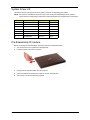
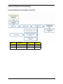
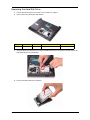
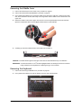
Removing the Battery Pack
1.
Slide the battery lock to the unlock position (1).
2.
Slide and hold the battery latch
the battery pack from its bay (b).
all the way through to release the battery pack (a) and then remove
Removing the SD Dummy Card
30
1.
Push against the card, as if you were pushing it further into the slot, letting the card spring out (a).
2.
Pull the SD dummy card out of its slot (b).
Acer Aspire 3935 Service Guide
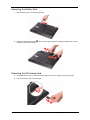
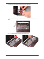
Removing the Lower Case Cover
1.
Perform the “Removing the Battery Pack” procedure on the previous page.
2.
Loosen the screws securing the lower case cover.
Type
Quantity
Color
Torque
Part Number
M2 x L4
3
Black
1.6 kgf-cm
86.00E13.524
3.
Pry loose the lower case cover from the main unit to remove it.
Acer Aspire 3935 Service Guide
31
Removing the Memory Modules
32
1.
Perform the “Removing the Lower Case Cover” procedure on page 31.
2.
Push out the latches on both sides of the DM1 slot.
3.
Remove the memory module from its slot.
4.
Repeat steps 2 and 3 to remove the DM2 slot module.
Acer Aspire 3935 Service Guide
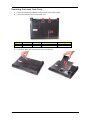
Removing the Hard Disk Drive
1.
Perform the “Removing the Lower Case Cover” procedure on page 31.
2.
Remove the screw securing the HDD bracket.
Type
Quantity
Color
Torque
Part Number
M2.5 x L5
1
Black
3.0 kgf-cm
86.00F87.735
3.
Grasp the black mylar tab and use it to slide the HDD assembly from its connector, and then remove the
HDD assembly from its compartment.
4.
Remove the HDD module from its bracket.
Acer Aspire 3935 Service Guide
33
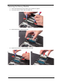
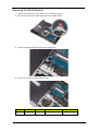
Removing the WLAN Module
34
1.
Perform the “Removing the Lower Case Cover” procedure on page 31.
2.
Disconnect the main and auxiliary antennas from the WLAN module.
3.
Release the WLAN antennas from their lower case latches.
4.
Remove the screw securing the WLAN module.
Type
Quantity
Color
Torque
Part Number
M2 x L3
1
Black
1.6 kgf-cm
86.00D91.723
Acer Aspire 3935 Service Guide
5.
Remove the WLAN module from its slot.
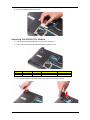
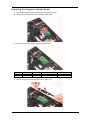
Removing the WWAN (3G) Module
1.
Perform the “Removing the Battery Pack” procedure on page 30.
2.
Loosen the screw securing the WWAN module compartment cover.
Type
Quantity
Color
Torque
Part Number
M2 x L4
1
Black
1.6 kgf-cm
86.00E13.524
3.
Pry loose the WWAN module compartment cover from the main unit to remove it.
Acer Aspire 3935 Service Guide
35
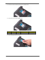
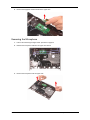
4.
Disconnect the main and auxiliary antennas from the WWAN module.
5.
Remove the screw securing the WWAN module.
Type
Quantity
Color
Torque
Part Number
M2 x L3
1
Black
1.6 kgf-cm
86.00D91.723
6.
36
Remove the WWAN module from its slot.
Acer Aspire 3935 Service Guide
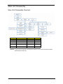
Wireless Module Antenna Cable Connection
The antenna cable connection for each wireless module option is shown in the following figures.
WLAN Module Cable Connection
Antenna Cable Color
Module Connector Code
Black
1
White
2
WWAN Module Cable Connection
Option 1
Option 2
Option
Antenna Cable Color
Module Connector Code
Option 1
Yellow
Main
Blue
Aux
Black
1
White
2
Gray
3
Option 2
Acer Aspire 3935 Service Guide
37
Main Unit Disassembly
Main Unit Disassembly Flowchart
Code
Part Number
Type
Color
B
86.00F87.735
M2.5 x L5
Black
C
86.00D91.723
M2 x L3
Black
D
86.00F80.723
M2 x L3
Black
E
86.00H50.624
M2 x L4
Silver
F
–
M2.5 spring
Black
CAUTION: To prevent from scratching or damaging the LCD panel, cover it with a protective film before
disassembling the main unit.
38
Acer Aspire 3935 Service Guide
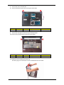
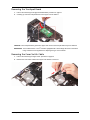
Removing the Middle Cover
1.
Perform the “Removing the Lower Case Cover” procedure on page 31.
2.
Perform the “Removing the WLAN Module” procedure on page 34.
3.
Use a plastic flat screwdriver to pry loose the middle cover. Start on the right side, continue to the center
side, move towards the left side, then finally on the hinge sides until the middle cover is released from the
upper case.
4.
Detach the middle cover from the upper case and turn it over the keyboard (a) to access its underside.
Open the media board cable connector (b) and disconnect the media cable (c).
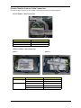
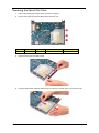
5.
Carefully pry loose the media board from the middle cover to detach it.
CAUTION: The media board is glued to the upper case. Remove the media board only if it is defective.
IMPORTANT: A circuit board that is >10 cm2 has been highlighted with a red rectangle as shown in the above
image. Follow the local regulations for disposing this type of circuit board.
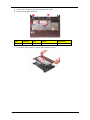
Removing the Keyboard
1.
Perform the “Removing the Middle Cover” procedure on page 39.
2.
Use a plastic flat screwdriver to push the latches on the top side of the keyboard.
Acer Aspire 3935 Service Guide
39
3.
Slide the keyboard towards the LCD module, then once it’s detached from the upper case, turn it over the
palmrest (a) to gain access to the keyboard cable. Open the keyboard cable connector (b) and disconnect
the keyboard cable (c).
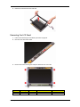
Removing the LCD Module
40
1.
Perform the “Removing the Keyboard” procedure on page 39.
2.
Disconnect the LCD cable from its mainboard connector.
3.
Release the LCD cable from its upper case latches.
Acer Aspire 3935 Service Guide
4.
Push both corners of the LCD cable connector through its upper case opening.
5.
Remove the black tape securing the WWAN antennas, and then release them from their upper case
latches.
6.
Pull out the WWAN and WLAN antennas from underneath the computer.
WWAN antennas
Acer Aspire 3935 Service Guide
WLAN antennas
41
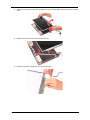
7.
Turn the unit over to the base side.
8.
Remove the bottom hinge screws securing the LCD module.
Type
Quantity
Color
Torque
Part Number
M2.5 x L5
2
Black
3.0 kgf-cm
86.00F87.735
9.
Turn the unit over again to remove the top LCD hinge screws.
10. Remove the top hinge screws securing the LCD module.
Type
Quantity
Color
Torque
Part Number
M2.5 x L5
2
Black
3.0 kgf-cm
86.00F87.735
11. Detach the LCD module from the main unit.
Proceed to page 57 for instructions on how to disassemble the LCD module.
42
Acer Aspire 3935 Service Guide
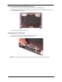
Removing the Upper Case
1.
Perform the “Removing the LCD Module” procedure on page 40.
2.
Disconnect the following system cables from their mainboard connectors.
Media board and speaker cables
Cover switch cable
Microphone cable
Fingerprint reader and touchpad board cables
3.
Turn the unit over to the base side.
4.
Remove the bottom screws securing the upper case to the lower case.
Type
Quantity
Color
Torque
Part Number
M2.5 x L5
5
Black
3.0 kgf-cm
86.00F87.735
Acer Aspire 3935 Service Guide
43
5.
Turn the unit over again to remove the top upper case screws.
6.
Remove the top upper case screws.
Type
Quantity
Color
Torque
Part Number
M2.5 x L5
5
Black
3.0 kgf-cm
86.00F87.735
7.
44
Pry loose the upper case from the lower case to detach the former.
Acer Aspire 3935 Service Guide
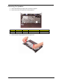
Removing the Speakers
1.
Perform the “Removing the Upper Case” procedure on page 43.
2.
Remove the screws securing the left and right speakers.
Type
Quantity
Color
Torque
Part Number
M2 x L3
2
Black
1.6 kgf-cm
86.00F80.723
3.
Remove the left and right speakers from the upper case.
Acer Aspire 3935 Service Guide
45
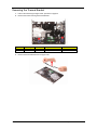
Removing the Thermal Bracket
1.
Perform the “Removing the Upper Case” procedure on page 43.
2.
Remove the screws securing the thermal bracket.
Type
Quantity
Color
Torque
Part Number
M2 x L3
2
Black
1.6 kgf-cm
86.00F80.723
3.
46
Remove the thermal bracket from the upper case.
Acer Aspire 3935 Service Guide
Removing the Fingerprint Reader Board
1.
Perform the “Removing the Thermal Bracket” procedure on page 46.
2.
Disconnect the fingerprint reader and touchpad board cables.
3.
Remove the screw securing the fingerprint reader bracket.
Type
Quantity
Color
Torque
Part Number
M2 x L3
1
Black
1.6 kgf-cm
86.00F80.723
4.
Remove the fingerprint reader bracket from the upper case.
Acer Aspire 3935 Service Guide
47
5.
Remove the fingerprint reader board from the upper case.
Removing the Microphone
48
1.
Perform the “Removing the Upper Case” procedure on page 43.
2.
Release the microphone cable from its upper case latches.
3.
Remove the microphone from the upper case.
Acer Aspire 3935 Service Guide
Removing the Touchpad Board
1.
Perform the “Removing the Fingerprint Reader Board” procedure on page 47.
2.
Carefully pry loose the touchpad board from the upper case to detach it.
CAUTION: The touchpad board is glued to the upper case. Remove the touchpad board only if it is defective.
IMPORTANT: A circuit board that is >10 cm2 has been highlighted with a red rectangle as shown in the above
image. Follow the local regulations for disposing this type of circuit board.
Removing the Cover Switch Cable
1.
Perform the “Removing the Upper Case” procedure on page 43.
2.
Release the cover switch cable from its upper case latches to remove it.
Acer Aspire 3935 Service Guide
49
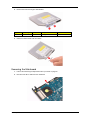
Removing the Optical Disc Drive
50
1.
Perform the “Removing the Upper Case” procedure on page 43.
2.
Remove the screws securing the ODD bezel to the lower case.
Type
Quantity
Color
Torque
Part Number
M2 x L3
3
Black
1.6 kgf-cm
86.00F80.723
3.
Detach the bezel from the ODD module.
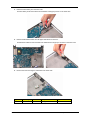
4.
Push the ODD module outward to detach it from its connector, and then pull it out of the lower case.
Acer Aspire 3935 Service Guide
5.
Remove the screw securing the ODD bracket.
Type
Quantity
Color
Torque
Part Number
M2 x L3
1
Black
1.6 kgf-cm
86.00F80.723
6.
Detach the ODD bracket from the module.
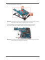
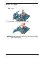
Removing the Mainboard
1.
Perform the “Removing the Optical Disc Drive” procedure on page 50.
2.
Disconnect the DC-in cable from the mainboard.
Acer Aspire 3935 Service Guide
51
3.
Detach the RTC battery from the lower case.
The RTC battery is still connected to the mainboard so simply lay it down on the lower case.
4.
Release the Bluetooth module from its upper case latches to remove it.
The Bluetooth module is still connected to the mainboard so simply lay it the down on the lower case.
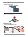
5.
52
Remove the screw securing the mainboard to the lower case.
Type
Quantity
Color
Torque
Part Number
M2 x L4
1
Silver
1.6 kgf-cm
86.00H50.624
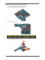
Acer Aspire 3935 Service Guide
6.
Remove the mainboard from the upper case.
IMPORTANT: A circuit board that is >10 cm2 has been highlighted with a red rectangle as shown in the above
image. Follow the local regulations for disposing this type of circuit board.
7.
Turn the mainboard over to access the RTC battery and Bluetooth module cable connectors.
8.
Disconnect the RTC battery and Bluetooth module cable from their mainboard connectors.
IMPORTANT: The RTC battery has been highlighted with a red rectangle in the above image. Detach the RTC
battery and follow the local regulations for disposing it.
Acer Aspire 3935 Service Guide
53
Removing the Heat Sink Fan (HSF) Assembly
1.
Perform the “Removing the Mainboard” procedure on page 51.
2.
Disconnect the HSF cable from its mainboard connector.
3.
Loosen the heat sink screws.
Type
Quantity
Color
Torque
Part Number
M2.5 spring
4
Black
2.0 kgf-cm
–
4.
54
Remove the heat sink fan from the mainboard.
Acer Aspire 3935 Service Guide
Removing the Processor
1.
Perform the “Removing the Heat Sink Fan (HSF) Assembly” procedure on page 54.
2.
Use a flat screwdriver to turn the processor socket lock counter-clockwise to the unlock position.
Torque: 2.5 kgf-cm
3.
Hold the processor by its edges and carefully remove it from its socket.
CAUTION: DO NOT lay the processor on its base to avoid bending or damaging the pins underneath it.
IMPORTANT: When installing a processor, note the golden arrow on the corner to make sure the processor is
properly oriented over the socket.
Acer Aspire 3935 Service Guide
55
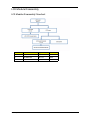
Removing the I/O Board
1.
Perform the “Removing the Mainboard” procedure on page 51.
2.
Remove the screws securing the I/O board.
Type
Quantity
Color
Torque
Part Number
M2 x L3
2
Black
1.6 kgf-cm
86.00D91.723
3.
Remove the heat sink fan from the mainboard.
Removing the DC-in Cable
56
1.
Perform the “Removing the Mainboard” procedure on page 51.
2.
Release the DC-in cable from its upper case latches to remove it.
Acer Aspire 3935 Service Guide
LCD Module Disassembly
LCD Module Disassembly Flowchart
Code
Part Number
Type
Color
C
86.00D91.723
M2 x L3
Black
E
86.00H50.624
M2 x L4
Black
G
86.00E09.622
M2 x L3
Silver
Acer Aspire 3935 Service Guide
57
Removing the LCD Bezel
1.
Perform the “Removing the LCD Module” procedure on page 40.
2.
Remove the rubber pads covering the LCD bezel screws.
3.
Remove the screws securing the LCD bezel.
Type
Quantity
Color
Torque
Part Number
M2 x L4
2
Silver
2.0 kgf-cm
86.00H50.624
4.
58
Carefully pry loose the bezel from the LCD case. Start on the hinge part (a), continue on the bottom side
(b), then to the left and right sides (c), and finally on the top side (d).
Acer Aspire 3935 Service Guide
5.
Detach the LCD bezel from the LCD case.
Removing the LCD Panel
1.
Perform the “Removing the LCD Bezel” procedure on page 58.
2.
Disconnect the CCD board cable.
3.
Remove the screws securing the LCD panel brackets to the LCD case.
Type
Quantity
Color
Torque
Part Number
M2 x L2
4
Silver
2.0 kgf-cm
86.00E09.622
Acer Aspire 3935 Service Guide
59
60
4.
Detach the LCD panel from the LCD case (a) and turn it 90° clockwise (b) to access the LCD-CCD coaxial
cable.
5.
Detach the LCD-CCD coaxial cable from the LCD case.
6.
Detach the LCD-CCD coaxial cable from the inverter board.
Acer Aspire 3935 Service Guide
Removing the LCD Panel Brackets
1.
Perform the “Removing the LCD Panel” procedure on page 59.
2.
Remove the screws securing the LCD panel brackets to the LCD case.
Type
Quantity
Color
Torque
Part Number
M2 x L4
4
Black
2.0 kgf-cm
86.00D91.723
3.
Remove the LCD panel brackets from the LCD case.
Acer Aspire 3935 Service Guide
61
Removing the WLAN and WWAN Antennas
1.
Perform the “Removing the LCD Panel Brackets” procedure on the previous page.
2.
Release the antennas from the LCD case latches, and then detach the aluminum foil tabs securing the
antenna boards to the LCD case.
3.
Detach the antennas from the LCD case.
Removing the CCD Board
1.
Perform the “Removing the LCD Panel” procedure on page 59.
2.
Detach the CCD board from the LCD case to remove it.
CAUTION: The CCD board is glued to the LCD case. Remove the CCD board only if it is defective.
62
Acer Aspire 3935 Service Guide
Chapter 4
Troubleshooting
This chapter describes the procedures for performing a BIOS recovery, clearing the BIOS pasword and
unlocking the HDD. It also lists the POST error indicators and BIOS beep codes, as well general
troubleshooting instructions.
Clearing a BIOS Password
To clear a lost BIOS password (user or supervisor password) you need to short the G26 hardware gap located
near the HDD connector.
H/W Gap
Default Setting
Function
G26
Open (normal)
Short to clear the user and supervisor passwords.
To clear a BIOS password:
1.
Turn off the computer and unplug all the peripherals connected to it.
2.
Unplug the power cord from the computer.
3.
Remove the battery pack according to the instructions described on page 30.
4.
Remove the lower case cover according to the instructions described on page 31.
5.
Locate the G26 gap. It is between the HDD connector and the south bridge chip
6.
Use an electrical conductivity tool to short the two contacts on the hardware gap together.
7.
While resting the tool on the two contacts, plug one end of the AC adapter into the DC-in jack and plug
one end to an electrical outlet.
8.
Press the power button to turn on the system.
9.
After the BIOS POST, remove the tool from the hardware gap.
10. Reinstall the HDD module, battery pack, and the lower case cover.
11. Turn on the computer and press F2 during bootup to access the Setup Utility.
12. Press F9 to load the system defaults.
13. Press F10 to save the changes you made and close the Setup Utility.
Acer Aspire 3935 Service Guide
63
Unlocking the Hard Drive
To regain access to your computer if you lose the HDD password, you need to generate a master password
and unlock your hard drive.
To unlock the hard drive:
1.
Open the computer in a DOS environment.
2.
Type the following command:
A\> unlock6 XXXXX
00
3.
Press Enter to display the command options.
4.
Select option 2 (upper case ASCII code), then press Enter.
5.
Write down the generated master password.
6.
Reboot the computer.
7.
In the HDD password prompt, type the master password generated in step 4, then press Enter.
BIOS Recovery
An interruption during a BIOS flash procedure (e.g. a power outage) can corrupt the BIOS code, which will
cause the system to go into an unbootable state. You need to access and execute the boot block program to
reboot the computer and recover the regular BIOS code.
Note the following when restoring the BIOS settings:
Make sure the battery pack is installed to the system and that the computer is connected to a UPS unit
during the BIOS recovery process.
The BIOS crisis recovery disk should be prepared in a computer running the Windows XP or Windows
Vista OS.
Creating the BIOS Crisis Recovery Disk
1.
Prepare a removable USB storage device with a capacity size greater than 10MB.
Note that all data on the USB storage device will be cleared during the creation of the crisis disk.
64
2.
Set up a computer running the Windows XP or Windows Vista operating system and plug in the USB
storage device into an available USB port.
3.
Decompress the Crisis Package Source.
4.
Select WINCRIS.EXE and then select Run as administrator.
5.
Keep the default settings and then click on the Start button.
6.
When the pop-up warning dialog box appears, click OK to create the crisis disk.
7.
Click No if you do not want to create another crisis disk.
8.
Eject and reconnect the USB removable storage device from the computer, and make sure it contains the
following three files:
•
BIOS.wph
•
MINIDOS.sys
•
PHLASH16.exe
Acer Aspire 3935 Service Guide
Performing a BIOS Recovery
1.
Shut down the BIOS failed-computer.
2.
Connect the USB storage device containing the BIOS recovery crisis disk files to the failed computer.
3.
Press and hold <Fn> + <Esc> keys (this is the BIOS recovery hotkey), then press the power button.
The system will now execute the BIOS recovery process. When the process is complete the computer will
automatically reboot.
4.
Disconnect the USB storage device from the computer.
5.
Perform a BIOS flash procedure to update the BIOS firmware.
POST Error Indicators
When a system error is detected during POST (Power On Self Text), the Setup Utility will switch to diagnostic
mode and will either:
•
Displays a POST error message, or
•
Emits a series of beep codes
POST Error Messages
POST error messages tell users what failure the system has detected. Some error messages could be related
to a hardware device. Others may indicate a problem with a device configuration. In some cases an error
message may include recommendations for troubleshooting or require that you press the Enter key to display
recommendations. Follow the instructions on the screen. It is recommended that you correct the error before
proceeding, even if the computer appears to boot successfully.
The table below lists the messages that the BIOS has defined and can display.
If your system displays one of the messages marked below with an asterisk (*), write down the code and
message and contact your Acer service provider.
IMPORTANT:
If your system fails after you make changes in the Setup menus, reboot the computer, enter
Setup again and load Setup defaults to correct the error.
Error Messages
Check or do the following in sequence:
Stuck Key
See “Keyboard or Auxiliary Input Device Check” section on
page 71.
System CMOS checksum bad - Default
configuration used
Real time clock error
Previous boot incomplete - Default
configuration used
Invalid System Configuration Data
Acer Aspire 3935 Service Guide
RTC battery
Run the BIOS Setup Utility to reconfigure the system time,
then reboot system.
RTC battery
Run the BIOS Setup Utility to reconfigure system time, then
reboot system.
Mainboard
Select “Load Setup Defaults” in the BIOS Setup Utility’s Exit
menu.
RTC battery
Mainboard
Select “Load Setup Defaults” in the BIOS Setup Utility’s Exit
menu.
Mainboard
65
Error Messages
Operating system not found
Check or do the following in sequence:
Power-on indicator turns off and LCD is
blank.
Power-on indicator turns on and LCD
is blank.
Power-on indicator turns on and LCD is
blank. POST is visible when using an
external CRT.
Power-on indicator turns on and a
blinking cursor is during POST.
Failure Fixed Disk
No beep, power-on indicator turns off and
LCD is blank.
No beep, power-on indicator turns on and
LCD is blank.
66
No beep, power-on indicator turns on and
LCD is blank. But you can see POST on an
external CRT.
No beep, power-on indicator turns on and a
blinking cursor shown on LCD during
POST.
No beep during POST but system runs
correctly.
Run the BIOS Setup Utility to check if the fixed disk and drive
A are properly identified.
Optical disc drive
Hard disk drive
Mainboard
Power source (battery pack and power adapter.) See “Power
System Check” section on page 72.
Make sure all connectors are connected tightly and correctly.
Reinstall the DIMM.
Mainboard
Power source (battery pack and power adapter.) See “Power
System Check” section on page 72.
Reconnect the LCD cable
Hard disk drive
LCD panel
Mainboard
Reconnect the LCD cable.
LCD panel
Mainboard
Make sure all connectors are connected tightly and correctly.
Mainboard
Reconnect the HDD connector.
Select “Load Setup Defaults” in the BIOS Setup Utility’s Exit
menu.
Hard disk drive
Mainboard
Power source (battery pack and power adapter). See “Power
System Check” on page 72
Make sure all connectors are connected tightly and correctly.
Reconnect the DIMM.
Mainboard
Power source (battery pack and power adapter). See “Power
System Check” on page 72
Reconnect the LCD cable.
Hard disk drive
LCD cable
LCD panel
Mainboard
Reconnect the LCD cable.
LCD panel
Mainboard
Make sure all connectors are connected tightly and correctly.
Mainboard
Speaker
Mainboard
Acer Aspire 3935 Service Guide
POST Beep Codes
When no POST error message is displayed but the computer stops during POST, listen for beep codes.
Code
Beeps
POST Routine Description
02h
Verify Real Mode
03h
Disable Non-Maskable Interrupt (NMI)
04h
Get CPU type
06h
Initialize system hardware
08h
Initialize chipset with initial POST values
09h
Set IN POST flag
0Ah
Initialize CPU registers
0Bh
Enable CPU cache
0Ch
Initialize caches to initial POST values
0Eh
Initialize I/O component
0Fh
Initialize the local bus IDE
10h
Initialize Power Management
11h
Load alternate registers with initial POST values
12h
Restore CPU control word during warm boot
13h
Initialize PCI Bus Mastering devices
14h
Initialize keyboard controller
16h
1-2-2-3
BIOS ROM checksum
17h
Initialize cache before memory autosize
18h
8254 timer initialization
1Ah
8237 DMA controller initialization
1Ch
Reset Programmable Interrupt Controller
20h
1-3-1-1
Test DRAM refresh
22h
1-3-1-3
Test 8742 Keyboard Controller
24h
Set ES segment register to 4 GB
26h
Enable A20 line
28h
Autosize DRAM
29h
Initialize POST Memory Manager
2Ah
Clear 215 KB base RAM
2Ch
1-3-4-1
RAM failure on address line xxxx*
2Eh
1-3-4-3
RAM failure on data bits xxxx* of low byte of memory bus
2Fh
30h
Enable cache before system BIOS shadow
1-4-1-1
RAM failure on data bits xxxx* of high byte of memory bus
32h
Test CPU bus-clock frequency
33h
Initialize Phoenix Dispatch Manager
36h
Warm start shut down
38h
Shadow system BIOS ROM
3Ah
Autosize cache
3Ch
Advanced configuration of chipset registers
3Dh
Load alternate registers with CMOS values
42h
Initialize interrupt vectors
Acer Aspire 3935 Service Guide
67
Code
Beeps
45h
46h
POST device initialization
2-1-2-3
Check ROM copyright notice
48h
Check video configuration against CMOS
49h
Initialize PCI bus and devices
4Ah
Initialize all video adapters in system
4Bh
QuietBoot start (optional)
4Ch
Shadow video BIOS ROM
4Eh
Display BIOS copyright notice
50h
Display CPU type and speed
51h
Initialize EISA board
52h
Test keyboard
54h
Set key click if enabled
58h
68
POST Routine Description
2-2-3-1
Test for unexpected interrupts
59h
Initialize POST display service
5Ah
Display prompt “Press F2 to enter SETUP”
5Bh
Disable CPU cache
5Ch
Test RAM between 512 and 640 KB
60h
Test extended memory
62h
Test extended memory address lines
64h
Jump to User Patch1
66h
Configure advanced cache registers
67h
Initialize Multi Processor APIC
68h
Enable external and CPU caches
69h
Setup System Management Mode (SMM) area
6Ah
Display external L2 cache size
6Bh
Load custom defaults (optional)
6Ch
Display shadow-area message
6Eh
Display possible high address for UMB recovery
70h
Display error messages
72h
Check for configuration errors
76h
Check for keyboard errors
7Ch
Set up hardware interrupt vectors
7Eh
Initialize coprocessor if present
80h
Disable onboard Super I/O ports and IRQs
81h
Late POST device initialization
82h
Detect and install external RS232 ports
83h
Configure non-MCD IDE controllers
84h
Detect and install external parallel ports
85h
Initialize PC-compatible PnP ISA devices
86h
Re-initialize onboard I/O ports
87h
Configure Motherboard Configurable Devices (optional)
88h
Initialize BIOS Data Area
89h
Enable Non-Maskable Interrupts (NMIs)
Acer Aspire 3935 Service Guide
Code
Beeps
POST Routine Description
8Ah
Initialize Extended BIOS Data Area
8Bh
Test and initialize PS/2 mouse
8Ch
Initialize floppy controller
8Fh
Determine number of ATA drives (optional)
90h
Initialize hard-disk controllers
91h
Initialize local-bus hard-disk controllers
92h
Jump to UserPatch2
93h
Build MPTABLE for multi-processor boards
95h
Install CD-ROM for boot
96h
Clear huge ES segment register
97h
98h
Fixup Multiprocessor table
1-2
Search for option ROMs. One long, two short beeps on checksum
failure.
99h
Check for SMART drive (optional)
9Ah
Shadow option ROMs
9Ch
Set up Power Management
9Dh
Initialize security engine (optional)
9Eh
Enable hardware interrupts
9Fh
Determine number of ATA and SCSI drives
A0h
Set time of day
A2h
Check key lock
A4h
Initialize Typematic rate
A8h
Erase F2 prompt
AAh
Scan for F2 key stroke
ACh
Enter SETUP
AEh
Clear Boot flag
B0h
Check for errors
B2h
POST done- prepare to boot operating system
B4h
1
One short beep before boot
B5h
Terminate QuietBoot (optional)
B6h
Check password (optional)
B9h
Prepare Boot
BAh
Initialize DMI parameters
BBh
Initialize PnP Option ROMs
BCh
Clear parity checkers
BDh
Display MultiBoot menu
BEh
Clear screen (optional)
BFh
Check virus and backup reminders
C0h
Try to boot with INT 19
C1h
Initialize POST Error Manager (PEM)
C2h
Initialize error logging
C3h
Initialize error display function
C4h
Initialize system error handler
Acer Aspire 3935 Service Guide
69
Code
Beeps
POST Routine Description
C5h
PnPnd dual CMOS (optional)
C6h
Initialize notebook docking (optional)
C7h
Initialize notebook docking late
C8h
Force check (optional)
C9h
Extended checksum (optional)
D2h
Unknown interrupt
BIOS Beep Codes for Boot Block in Flash ROM
Code
Beeps
Initialize the chipset
E1h
Initialize the bridge
E2h
Initialize the CPU
E3h
Initialize the system timer
E4h
Initialize system I/O
E5h
Check force recovery boot
E6h
Checksum BIOS ROM
E7h
Go to BIOS
E8h
Set Huge Segment
E9h
Initialize Multiprocessor
EAh
Initialize OEM special code
EBh
Initialize PIC and DMA
ECh
Initialize Memory type
EDh
Initialize Memory size
EEh
Shadow Boot Block
EFh
System memory test
F0h
Initialize interrupt vectors
F1h
Initialize Run Time Clock
F2h
Initialize video
F3h
F4h
70
For Boot Block in Flash ROM
E0h
Initialize System Management Mode
1
Output one beep before boot
F5h
Boot to Mini DOS
F6h
Clear Huge Segment
F7h
Boot to Full DOS
Acer Aspire 3935 Service Guide
Troubleshooting Procedure
Perform the following procedure to determine the cause of a computer problem.
1.
Obtain the failure symptoms in as much detail as possible.
2.
Verify the symptoms by attempting to recreate the failure by running the diagnostic tests or repeating the
same operation.
3.
Disconnect all power source from the computer when performing an assembly or disassembly procedure.
4.
Perform the following visual inspection before you continue.
•
Power cords are properly connected and secured.
•
There are no obvious shorts or opens.
•
There are no burned or heated components.
•
All components appear normal.
System Check Procedures
NOTE: The diagnostic tests are intended to test only Acer products. Non-Acer products, prototype cards, or
modified options can give false errors and invalid system responses.
External CD/DVD-ROM Drive Check
Perform the following procedures to isolate the possible problem a controller, drive, or CD-ROM.
1.
Boot from the diagnostic disc and start the diagnostic programs.
2.
Check if the CD-ROM Test result is pass.
3.
Follow the on-screen instructions.
If an error occurs, reconnect the drive to the connector on the mainboard. If the error persists, do the following:
1.
Reconnect the CD/DVD-ROM drive.
2.
Replace the CD/DVD-ROM drive.
3.
Replace the mainboard.
Keyboard or Auxiliary Input Device Check
Remove the external keyboard if the internal keyboard is to be tested.
If the internal keyboard does not work or an unexpected error occurs, make sure that the flexible cable
extending from the internal keyboard is correctly connected to the mainboard. If the keyboard cable
connection is correct, run the Keyboard Test.
If the tests detect a keyboard problem, do the following procedures in sequence to correct the problems. Do
not replace a non-defective FRU:
1.
Reconnect the keyboard cable.
2.
Replace the keyboard.
3.
Replace the mainboard.
The following auxiliary input devices are supported by this computer:
Numeric keypad
External keyboard
If any of these devices do not function, reconnect the cable and repeat above procedures.
Acer Aspire 3935 Service Guide
71
Memory Check
NOTE: Make sure that the DIMM is properly installed into the connector. A loose connection can cause an
error.
Do the following:
1.
Boot from the diagnostic diskette and start the diagnostic program.
2.
Go to the diagnostic memory in the test items.
3.
Press F2 in the test items.
4.
Follow on-screen instructions.
Power System Check
Do the following:
1.
Remove the battery pack.
2.
Connect the power adapter and check the power supply.
3.
Disconnect the power adapter and install the battery pack; then check that power supply.
Check the Power Adapter
Unplug the power adapter cable from the system and measure the output voltage at the plug of the power
adapter cable.
1.
If the voltage is not correct, replace the power adapter.
2.
If the voltage is within range, do the following:
a.
Replace the mainboard.
b.
If the problem is not resolved, see “Undetermined Problems” section on page 73.
c.
If the voltage is not correct, go to the next step.
NOTE: An audible noise from the power adapter does not always indicate a defect.
3.
If the power-on indicator does not light up, check if the adapter’s power cord is properly connected to the
system.
4.
If the operational charge does not work, see “Check the Battery Pack” on page 72.
Check the Battery Pack
Do the following:
Using the Power Management program to identify whether a problem occurs while the battery pack during
recharge or discharge:
1.
Open Power Management in the Control Panel.
2.
In the Power Meter tab, confirm if the parameters for Current Power Source and Total Battery Power
Remaining are correct.
3.
Repeat the steps 1 and 2 for both battery pack and adapter.
Using hardware to identify whether you should replace the battery pack or not:
1.
Power off the system.
2.
Remove the battery pack and measure the voltage between terminals one (+) and seven (-). There are
seven terminals here.
3.
If the voltage is still less than 7.5 Vdc after recharging, replace the battery pack.
If the battery status indicator does not light up, remove the battery pack. If the charge indicator still does not
light up, replace the AC/DC charger board.
72
Acer Aspire 3935 Service Guide
Touchpad Check
If the touchpad doesn’t work, do the following procedures in sequence to correct the problem. Do not replace
a non-defective FRU:
1.
After rebooting, run the Tracking Pad PS2 Mode Driver. For example Syn touch driver.
2.
Run the utility with the PS/2 mouse function and check if the mouse is working.
3.
If the PS/2 mouse does not work, then click if the main board to switch board FPC is connected properly.
4.
If the mainboard to switch board FPC is connected correctly, then check if the FFC on the touchpad board
is connected properly.
5.
If the FFC on the touchpad board is connected correctly, check if LS851 JP1 Pin6 = 5V are pules. If yes,
then replace switch board. If not, then go to the next step.
6.
Replace the touchpad board.
7.
If the touchpad still does not work, then replace the FPC on touchpad board.
After you use the touchpad, the pointer drifts on the screen for a short time. This self-acting pointer movement
will occur when a slight, steady pressure is applied to the touchpad pointer. This symptom is not a hardware
problem. No actions are necessary to be taken if the pointer movement stops in a short period of time.
Intermittent Problems
Intermittent system hang problems can be caused by a variety of reasons that have nothing to do with a
hardware defect, such as: cosmic radiation, electrostatic discharge, or software errors. FRU replacement
should be considered only when a recurring problem exists.
When analyzing an intermittent problem, do the following:
1.
Run the advanced diagnostic test for the mainboard in loop mode at least 10 times.
2.
If no error is detected, do not replace any FRU.
3.
If any error is detected, replace the FRU. Rerun the test to verify that there are no more errors.
Undetermined Problems
NOTE: Verify that all attached devices are supported by the computer.
NOTE: Verify that the power supply being used at the time of the failure is operating correctly. (See “Power
System Check” on page 72)
Follow procedures below to isolate the failing FRU. Do not isolate non-defective FRU.
1.
Power off the computer.
2.
Visually check them for damage. If any problems are found, replace the FRU.
3.
Remove or disconnect all of the following devices:
•
Non-Acer devices
•
Printer, mouse, and other external devices
•
Battery pack
•
Hard disk drive
•
DIMM
•
CD/DVD-ROM drive
4.
Power on the computer.
5.
Determine if the problem has been resolved.
6.
If the problem does not recur, reconnect the removed devices one at a time until you find the failed FRU.
7.
If the problem persists, replace the mainboard, and then LCD assembly (one at a time). Do not replace a
non-defective FRU.
Acer Aspire 3935 Service Guide
73
Online Support Information
This section describes online technical support services available to help you repair your Acer products.
If you are a distributor, dealer, ASP or TPM, please refer your technical queries to your local Acer branch
office. Acer branch offices and regional business units can access our website. However some information
sources will require a user ID and password. These can be obtained directly from Acer CSD Taiwan.
Acer's website offers you convenient and valuable support resources whenever you need them.
In the Technical Information section you can download information on all Acer notebook, desktop and server
models including:
Service guides for all models
User's manuals
Training materials
BIOS updates
Software utilities
Spare parts lists
TABs (Technical Announcement Bulletin)
For these purposes, we have included a PDF file to facilitate the problem-free downloading of our technical
material.
Also available on this website are:
Detailed information on Acer's International Traveler's Warranty (ITW)
Returned material authorization procedures
An overview of all the support services we offer, accompanied by a list of telephone, fax and email
contacts for all your technical queries.
We are always looking for ways to optimize and improve our services, so if you have any suggestions or
comments, please do not hesitate to communicate these to us.
74
Acer Aspire 3935 Service Guide
Chapter 5
System Architecture
This chapter shows the mainboard layout and block diagram of the Acer Aspire 3935 system.
Mainboard Layout
This section shows the major mainboard components
Top View
Item
Code
Component
1
DC1
DC-in jack cable connector
2
LAUNCH1
Media board cable connector
3
SPKR1
Speaker cable connector
4
SIM1
SIM card slot (not externally accessible)
5
RJ45
Ethernet port
6
U58
USB 2.0 port
7
KB1
Keyboard cable connector
8
TPAD1
Touchpad board cable connector
9
FPCN1
Fingerprint reader board cable connector
10
CARD1
5-in-1 card reader module
11
MIC1
Microphone cable connector
12
HALL1
Cover switch cable connector
Acer Aspire 3935 Service Guide
75
Item
Code
Component
13
LCD1
LCD-CCD coaxial cable connector
Bottom View
76
Item
Code
Component
1
MINI1
WWAN module slot
2
DM1
DIMM 1 slot
3
DM2
DIMM 2 slot
4
BAT1
Battery pack connector
5
FAN1
Heat sink fan cable connector
6
CPU1
Processor socket
7
CRT1
VGA port
8
USB1
9
USB2
10
MICIN1
Microphone-in jack
11
LOUT1
Line-out jack (with S/PDIF support)
12
SATA1
HDD module connector
13
SB1
Intel ICH9M chipset
14
BT1
Bluetooth module cable connector
15
ODD1
ODD module connector
16
MINI2
WLAN module slot
17
NB1
Mobile Intel GM45 or GL40 GMCH
18
RTC1
RTC battery cable connector
USB 2.0 ports
Acer Aspire 3935 Service Guide
Block Diagram
The core subsystems of the Acer Aspire 3935 system are depicted in the following block diagram.
Acer Aspire 3935 Service Guide
77
78
Acer Aspire 3935 Service Guide
Chapter 6
Field Replaceable Unit (FRU) List
This chapter gives you the FRU (Field Replaceable Unit) listing of the Acer Aspire 3935 computer global
configurations. Refer to this list when ordering for repair parts or for RMA (Return Merchandise Authorization).
IMPORTANT: Part number changes will not be noted in this printed Service Guide. The part numbers listed in
this Service Guide may differ from those given to regional AUTHORIZED SERVICE
PROVIDERS. You MUST use the local FRU list provided by your regional office to order FRU
parts for repair and service of customer machines. Make sure that you are using the most upto-date information available on your regional web site or channel when ordering FRU parts.
NOTE: Follow the local government regulations or the rules set by your regional office on how to return or
dispose of defective parts.
Acer Aspire 3935 Service Guide
79
Acer Aspire 3935 Exploded Diagram
80
Acer Aspire 3935 Service Guide
No.
Component
Part Name
Part Number
1
LCD case
LED LCD COVER 13.3" COPPER BROWN W/
BRACKET&HINGE&ANTENNA*2 (NONE 3G)
60.PAD01.005
2
LCD bezel
LCD BEZEL 13.3" FLUSH CLASS W/CAMERA HOLE
60.PAD01.004
3
Upper case
UPPER CASE COPPER BROWN W/HALL SENSOR
CABLE & MICROPHONE & SPEAKER&NAME PLATE W
FINGER PRINT HOLE
60.PAD01.002
4
Middle cover
MIDDLE COVER NONE 3G
42.PAD01.001
5
Lower case
LOWER CASE W/DC-IN CABLE
60.PAD01.001
6
Battery pack
BATTERY PANASONIC AS-2009B LI-ION 4S1P
PANASONIC 4 CELL 2900MAH MAIN COMMON
BT.00405.010
BATTERY SANYO LI-ION 4CELL 2600MAH
BT.00403.017
BATTERY PANASONIC AS-2009B LI-ION 4S2P
PANASONIC 8 CELL 5800MAH MAIN COMMON
BT.00805.012
7
WWAN module
compartment cover
WIRELESS LAN COVER
42.PAD01.003
8
Lower case cover
UNITLOAD COVER
42.N4401.002
9
Mainboard
MAINBOARD SM30 UMA GM45 ICH9M LF W/RTC
BATTERY W/O MODEM BOARD NONE 3G
MB.PAD01.001
10
ODD bezel
DVD-RW SUPER-MULTI BEZEL
42.PAD01.005
DVD-RW SUPER-MULTI SLOT-IN BEZEL
42.PAD01.006
Acer Aspire 3935 Service Guide
81
Acer Aspire 3935 FRU List
System Model: ACER_ASPIRE 3935 UMACFPCC_SM30_MV(NO: S2.PAD0X.002/3/4)
Category
Part Name
Part Number
ADAPTER 65W 19V DELTA SADP-65KB BFJG
AP.06501.014
ADAPTER 65W 19V DELTA SADP-65KB DFJ
YELLOW LED LF
AP.06501.023
ADAPTER 65W LITEON PA-1650-02AC REV.A07
LF LEVEL-4
AP.06501.022
ADAPTER 65W 19V HIPRO HP-OK065B13 LV4
YELLOW LED LF
AP.06503.023
ADAPTER 65W 3PIN DELTA SADP-65KB BFJA LF
LEVEL-4 FOR OBL ONLY
AP.0650A.011
POWER CORD 10A 250V SWISS
27.01518.691
POWER CORD 10A 250V 3PIN SWISS BK
27.01518.581
POWER CORD 10A 250V ARGENTINE
27.01518.0U1
POWER CORD 10A 125V US
27.01518.641
POWER CORD 10A 125V 3PIN US BK
27.01518.521
POWER CORD 7A 250V 2PIN KOREAN
27.01518.531
POWER CORD 3A 250V 3PIN UK
27.03118.001
POWER CORD 5A 250V 3PIN UK BK
27.01518.541
POWER CORD 7A 125V 2PIN JAPAN
27.01518.551
POWER CORD 10A 3PIN BK DENMARK
27.01518.671
POWER CORD 10A 250V 3PIN DENMARK BK
27.01518.561
POWER CORD 10A 250V 3PIN BK SOUTH
AFRICA
27.01518.681
POWER CORD 16A 250V SOUTH AFRICA BK
27.01518.571
POWER CORD 10A 250V 3PIN CHINA
27.01518.701
POWER CORD 10A 250V 3PIN CHINA BK
27.01518.591
POWER CORD 10A 250V 3PIN ITALY
27.01518.711
POWER CORD 10A 250V 3PIN ITALY BK
27.01518.611
POWER CORD 2.5A 250V AUSTRALIA
27.01518.621
POWER CORD 2.5A 250V SOUTH AFRICA BK
(INDIA)
27.01518.721
POWER CORD 10A 250V SOUTH AFRICA BK
(INDIA)
27.01518.631
POWER CORD 7A 125V 2PIN JAPAN BK
27.01518.661
POWER CORD 250V 10A 3PIN ISRAEL
27.01518.761
POWER CORD 10A 250V 1.8M BRAZIL BLK
27.01518.A41
POWER CORD ACA / ACNZ
27.03218.051
POWER CORD 7.5A 250V 3P AUSTRALIA BK
27.03218.021
POWER CORD 7A 125V 2PIN JAPAN
27.03518.161
POWER CORD 250V 3PIN EUR BK
27.01518.731
POWER CABLE 16A 250V 3PIN EUR BK
27.01518.601
Adapter
Power cord
82
Acer Aspire 3935 Service Guide
Category
Part Name
Part Number
POWER CORD 2.5A 125V USA
27.01518.A11
POWER CORD 2.5A 125V 1.8M BLACK
TAIWANESE
27.01518.781
BATTERY PANASONIC AS-2009B LI-ION 4S1P
PANASONIC 4 CELL 2900MAH MAIN COMMON
BT.00405.010
BATTERY SANYO LI-ION 4CELL 2600MAH
BT.00403.017
BATTERY PANASONIC AS-2009B LI-ION 4S2P
PANASONIC 8 CELL 5800MAH MAIN COMMON
BT.00805.012
MAINBOARD SM30 UMA GM45 ICH9M LF W/RTC
BATTERY W/O MODEM BOARD NONE 3G
MB.PAD01.001
IO BOARD W/O 3G CARD READER
55.PAD01.003
MULTI-MEDIA BOARD
55.PAD01.001
TOUCHPAD SYNAPTICS TM-01262-002
56.PAD01.001
FINGER PRINT BOARD
55.PAD01.002
TRANSFER CONNECTOR BOARD FOR 2ND 2.5"
HDD
55.PAD01.004
Power cord (continuation)
Battery pack
Boards
Mainboard
I/O board
Media board
Touchpad board
Fingerprint reader board
Secondary HDD transfer board
Acer Aspire 3935 Service Guide
83
Category
Part Name
Part Number
LAN INTEL WLAN 533AN_MMWG2 SHIRLEY
PEAK 5300 ME ENABLE / MM#899545
(CENTRINO 2 WITH VPRO)
KI.SPM01.009
WIRELESS LAN BOARD 512AN_MMWG SHIRLEY
PEAK 5100 MM#895361
KI.SPM01.003
LAN INTEL WLAN 512AN_HMWG Shirley Peak
5100 MM#895373
KI.SPH01.003
Option 3G GTM382
LC.21300.007
3G UNDP-1
LC.21300.005
BLUETOOTH BOARD FOXCONN BCM2045 V2
T60H928.11
BT.21100.005
MULTI-MEDIA BOARD CABLE
50.PAD01.001
TOUCHPAD CABLE
50.PAD01.003
FINGER PRINT BOARD CABLE
50.PAD01.002
BLUETOOTH BOARD CABLE
50.PAD01.004
DC-IN CABLE
RESERVE
HALL SENSOR CABLE
RESERVE
LED LCD/CAMERA CABLE
50.PAD01.005
LED LCD/CAMERA CABLE
50.PAD01.005
WLAN module
WWAN (3G) module
Bluetooth module
Cables
Media board cable
Touchpad board cable
Fingerprint reader board cable
Bluetooth module cable
DC-in cable
Cover switch cable
LCD-CCD coaxial cable
84
Acer Aspire 3935 Service Guide
Category
Part Name
Part Number
LOWER CASE W/DC-IN CABLE
60.PAD01.001
UNITLOAD COVER
42.N4401.002
WIRELESS LAN COVER
42.PAD01.003
UPPER CASE COPPER BROWN W/HALL
SENSOR CABLE & MICROPHONE &
SPEAKER&NAME PLATE W FINGER PRINT HOLE
60.PAD01.002
MIDDLE COVER NONE 3G
42.PAD01.001
TOUCHPAD BRACKET
33.PAD01.001
OPTICAL BRACKET
33.PAD01.002
ODD DUMMY COVER FOR 2.5" HDD
42.PAD01.007
DVD-RW SUPER-MULTI BEZEL
42.PAD01.005
DVD-RW SUPER-MULTI SLOT-IN BEZEL
42.PAD01.006
Case/cover/bracket assembly
Lower case
Lower case cover
WWAN module compartment cover
Upper case
Middle cover
Fingerprint reader board bracket
ODD bracket
ODD cover
ODD bezel
Acer Aspire 3935 Service Guide
85
Category
Part Name
Part Number
HDD BRACKET 1.8
33.PAD01.003
HDD BRACKET 2.5
33.PAD01.004
HDD COVER FOR 5MM 1.8" HDD&SDD
60.4BT09.001
HDD COVER FOR 5MM 1.8" HDD&SDD
42.PAD01.002
HDD COVER FOR 8MM 1.8" HDD&SDD
60.4BT05.001
HDD COVER FOR 8MM 1.8" HDD&SDD
42.PAD01.008
CARD READER DUMMY CARD COPPER BROWN
W/LOGO
42.PAD01.004
LED LCD COVER 13.3" COPPER BROWN W/
BRACKET&HINGE&ANTENNA*2 (NONE 3G)
60.PAD01.005
LCD BEZEL 13.3" FLUSH CLASS W/CAMERA
HOLE
60.PAD01.004
LCD GLASS 13.3
60.4BT33.001
LCD GLASS 13.3
60.4BT35.001
LCD GLASS 13.3
60.4BT14.001
HDD bracket
HDD cover
SD dummy card
LCD case
LCD bezel
LCD glass
86
Acer Aspire 3935 Service Guide
Category
Part Name
Part Number
SODIMM 1GB DDRIII 1066MHZ MICRON
MT8JSF12864HY-1G1D1
KN.1GB0B.028
SODIMM 1GB DDRIII 1066MHZ ELPIDA
EBJ11UE6BAU0-AE-E
KN.1GB04.003
SODIMM 1GB DDRIII 1066MHZ SAMSUNG
M471B2874DZ1-CF8
KN.1GB09.009
SODIMM 1GB DDRIII 1066MHZ SAMSUNG
M471B2873EH1-CF8
KN.1GB0B.019
SODIMM 2GB DDRIII 1066MHZ SAMSUNG
M471B5673EH1-CF8
KN.2GB0G.009
SODIMM 2GB DDRIII 1066MHZ MICRON
MT16JSF25664HY-1G1D1
KN.2GB0B.012
SODIMM 2GB DDRIII 1066MHZ ELPIDA
EBJ21UE8BAU0-AE-E
KN.2GB04.004
SODIMM 2GB DDRIII 1066MHZ SAMSUNG
M471B5673DZ1-CF8
KN.2GB09.002
SODIMM 2GB DDRIII 1066MHZ HYNIX
HMT125S6AFP8C-G7N0
KN.2GB0B.005
CPU INTEL CORE2DUAL P8600 PGA 2.4G 1066
25W 3M
KC.86001.DPP
CPU INTEL CORE2DUAL P8700 2.53G 3M 1066
25W R-0
KC.87R01.DPP
CPU INTEL CORE2DUAL P7350 PGA 2.0G 3M
1066 25W
KC.73501.DPP
CPU INTEL CORE2DUAL P7450 2.13G 3M 1066 TJ
NOVT
KC.74501.DPP
CPU INTEL CORE2DUAL PENRYN P8400 2.26G
3M 1066 25W R-0
KC.84R01.DPP
CPU INTEL CORE2DUAL P8600 2.4G 3M 1066
25W R-0
KC.86R01.DPP
CPU INTEL CORE2DUAL P9500 2.53G 6M 1066
25W E-0
KC.95E01.DPP
CPU HEATSINK UMA W/FAN
60.PAD01.007
UPPER CASE THERMAL PIPE
60.PAD01.003
Memory module
Processor
Heat sink
Heat sink fan assembly
Thermal bracket
Acer Aspire 3935 Service Guide
87
Category
Part Name
Part Number
DVD-RW SUPER-MULTI MODULE 8X 9.5MM
TRAY-IN SATA
6M.PAD01.001
DVD-RW SUPER-MULTI MODULE 8X 9.5MM
SLOT-IN SATA
6M.PAD01.002
ODD TOSHIBA SUPER-MULTI DRIVE 8X 9.5MM
TRAY DL TS-U633A LF SATA GBAS2.0 W/O
BEZEL
KU.0080D.043
ODD TOSHIBA SUPER-MULTI DRIVE 8X 9.5MM
SLOT-IN SATA DL TS-D633A LF W/O BEZEL
KU.00807.063
ODD HLDS SUPER-MULTI DRIVE 8X 9.5MM TRAY
DL GU10N LF SATA GBAS2.0 W/O BEZEL
KU.00801.031
DVD SUPER MULTI DRIVE 8X 9.5MM SLOT-IN
SATA PANASONIC UJ867 LF W/O BEZEL
KU.00801.029
HDD 60GB 5400RPM 1.8" SATA SAMSUNG
HS06VHF/ACE LF F/W:3AK103C4
KH.0600B.005
HDD 80GB 5400RPM 1.8" SATA SAMSUNG
HS08VHF/ACE LF F/W:3AK103C4
KH.08004.013
HDD 80GB 5400RPM 1.8" SATA TOSHIBA
MK8017GSG SAPPHIRE BS8MB LF F/W:SP002A
KH.0800B.008
HDD 120GB 5400RPM 1.8" SATA TOSHIBA
MK1229GSG OPAL BSLF F/W:PS110
KH.1200B.004
HDD 120GB 5400RPM 1.8" SATA SAMSUNG
HS12VJF/ACE LF F/W:3AL103C4
KH.12004.010
HDD 160GB 5400RPM 1.8" SATA TOSHIBA
MK1629GSG OPAL BS LF F/W:PS110J
KH.1600B.004
HDD 160GB 5400RPM 1.8" SATA SAMSUNG
HS16VJF/ACE LF F/W:3AL103C4
KH.16004.007
HDD 250GB 5400RPM 1.8" SATA TOSHIBA
MK2529GSG OPAL BS LF F/W:PS110J
KH.25004.004
HDD 160GB 5400RPM 2.5" SATA HGST
HTS543216L9A300 F/W:C30C
KH.16001.034
HDD 160GB 5400RPM 2.5" SATA WD
WD1600BEVT-22ZCT0 FW:11.01A11
KH.16007.019
HDD 250GB 5400RPM SATA HGST
HTS545025B9A300 PANTHER-B LF
KH.25008.021
HDD 250GB 5400RPM SATA WD WD2500BEVT22ZCT0 F/W:11.01A11
KH.25007.015
HDD 320GB 5400RPM SATA SEAGATE
ST9320320AS F/W:2010
KH.32001.008
HDD 320GB 5400RPM SATA TOSHIBA
MK3255GSX LIBRA LF F/W:FG010J
KH.32008.013
HDD 320GB 5400RPM SATA HGST
HTS545032B9A300 PANTHER B LF
KH.32004.002
HDD 320GB 5400RPM SATA WD WD3200BEVT22ZCT0 ML125 F/W:01.01A01
KH.32007.007
DVD-RW drive
Hard disk drive
1.8-in SATA hard disk drive
2.5-in SATA hard disk drive
88
Acer Aspire 3935 Service Guide
Category
Part Name
Part Number
2.5-in SATA hard disk drive (continuation)
HDD 500GB 5400RPM HGST SATA
HTS545050B9A300 PANTHER B LF
KH.50008.013
HDD 500GB 5400RPM WD SATA WD5000BEVT22ZAT0 F/W:01.01A01
KH.50007.009
SSD 64GB 1.8" SATA SAMSUNG RBX
MMCRE64G8MPP-0VA MLC
KF.0640B.001
SSD 80GB 1.8" SATA INTEL X18-M
SA1MH080G105 901461
KF.0800N.003
SSD 128GB 1.8" SATA SAMSUNG RBX
MMCQE28G8MUP-0VA MLC
KF.1280B.001
KEYBOARD 86KS NSK-AM01D AC4P SM30
INTERNAL14 STANDARD BLACK PAINTING US
INTERNATIONAL
KB.I140A.112
KEYBOARD 86KS NSK-AM00L AC4P SM30
INTERNAL14 STANDARD BLACK PAINTING
GREEK
KB.I140A.097
KEYBOARD 86KS NSK-AM002 AC4P SM30
INTERNAL14 STANDARD BLACK PAINTING
TAIWAN
KB.I140A.092
KEYBOARD 86KS NSK-AM003 AC4P SM30
INTERNAL14 STANDARD BLACK PAINTING
THAILAND
KB.I140A.109
KEYBOARD 86KS NSK-AM00H AC4P SM30
INTERNAL14 STANDARD BLACK PAINTING US
INTERNATIONAL W/ HEBREW
KB.I140A.113
KEYBOARD 86KS NSK-AM00A AC4P SM30
INTERNAL14 STANDARD BLACK PAINTING
ARABIC
KB.I140A.088
KEYBOARD 86KS NSK-AM00R AC4P SM30
INTERNAL14 STANDARD BLACK PAINTING
RUSSIAN
KB.I140A.104
KEYBOARD 87KS NSK-AM00U AC4P SM30
INTERNAL14 STANDARD BLACK PAINTING UK
KB.I140A.111
KEYBOARD 87KS NSK-AM00W AC4P SM30
INTERNAL14 STANDARD BLACK PAINTING
SWEDEN
KB.I140A.107
KEYBOARD 87KS NSK-AM00F AC4P SM30
INTERNAL14 STANDARD BLACK PAINTING
FRENCH
KB.I140A.095
KEYBOARD 87KS NSK-AM006 AC4P SM30
INTERNAL14 STANDARD BLACK PAINTING
PORTUGUESE
KB.I140A.103
KEYBOARD 87KS NSK-AM01F AC4P SM30
INTERNAL14 STANDARD BLACK PAINTING SLO/
CRO
KB.I140A.105
KEYBOARD 87KS NSK-AM01B AC4P SM30
INTERNAL14 STANDARD BLACK PAINTING
BRAZILIAN PORTUGUESE
KB.I140A.090
Solid state drive
Keyboard
Acer Aspire 3935 Service Guide
89
Category
Part Name
Part Number
KEYBOARD 87KS NSK-AM000 AC4P SM30
INTERNAL14 STANDARD BLACK PAINTING
SWISS/G
KB.I140A.108
KEYBOARD 87KS NSK-AM00D AC4P SM30
INTERNAL14 STANDARD BLACK PAINTING
DANISH
KB.I140A.093
KEYBOARD 87KS NSK-AM00E AC4P SM30
INTERNAL14 STANDARD BLACK PAINTING
ITALIAN
KB.I140A.099
KEYBOARD 87KS NSK-AM01A AC4P SM30
INTERNAL14 STANDARD BLACK PAINTING
BELGIUM
KB.I140A.089
KEYBOARD 87KS NSK-AM00G AC4P SM30
INTERNAL14 STANDARD BLACK PAINTING
GERMAN
KB.I140A.096
KEYBOARD 87KS NSK-AM00N AC4P SM30
INTERNAL14 STANDARD BLACK PAINTING
NORWEGIAN
KB.I140A.102
KEYBOARD 87KS NSK-AM00Q AC4P SM30
INTERNAL14 STANDARD BLACK PAINTING
HUNGARIAN
KB.I140A.098
KEYBOARD 87KS NSK-AM00S AC4P SM30
INTERNAL14 STANDARD BLACK PAINTING
SPANISH
KB.I140A.106
KEYBOARD 87KS NSK-AM00T AC4P SM30
INTERNAL14 STANDARD BLACK PAINTING
TURKISH
KB.I140A.110
KEYBOARD 87KS NSK-AM01K AC4P SM30
INTERNAL14 STANDARD BLACK PAINTING
NORDIC
KB.I140A.101
KEYBOARD 87KS NSK-AM02A AC4P SM30
INTERNAL14 STANDARD BLACK PAINTING
FREBCH/ARABIC
KB.I140A.094
KEYBOARD 87KS NSK-AM02M AC4P SM30
INTERNAL14 STANDARD BLACK PAINTING US
W/CANADIAN FRENCH
KB.I140A.114
KEYBOARD 87KS NSK-AM013 AC4P SM30
INTERNAL14 STANDARD BLACK PAINTING
CZECH/SLOVAK
KB.I140A.091
KEYBOARD 91KS NSK-AM00J AC4P SM30
INTERNAL14 STANDARD BLACK PAINTING
JAPANESE
KB.I140A.100
Keyboard (continuation)
90
Acer Aspire 3935 Service Guide
Category
Part Name
Part Number
ASSEMBLY LED LCD MODULE 13.3" WXGA
GLARE COPPER BROWN W/
ANTENNA*3&CAMERA&GLASS (NONE 3G)
6M.PAD01.004
ASSEMBLY LED LCD MODULE 13.3" WXGA
GLARE COPPER BROWN W/
ANTENNA*2&CAMERA&GLASS (NONE 3G)
6M.PAD01.003
LED LCD 13.3" WXGA GLARE AUO B133XW01 V2
LF 220NIT 8MS 500:1
LK.1340D.001
LED LCD 13.3" WXGA GLARE LG LP133WH2TLA3 LF 220NIT 16MS 500:1
LK.13305.002
SPEAKER
23.PAD01.001
MICROPHONE
RESERVE
CAMERA 0.3M SUYIN CN0316-S30C-OV06-1
57.PAD01.001
LCD SCREW RUBBER
47.N4401.001
SCRW M2X3 #1 RED NYLON ROHS
86.00D91.723
SCRW M2X4L NI NYLOK
86.00H50.624
SCRW M2 L2 D=3.5MM T=0.3MM
86.00E09.622
M2 x L4
86.00E13.524
M2.5 x L5
86.00F87.735
M2 x L3
86.00F80.723
LCD panel
Miscellaneous
Speakers
Microphone
Webcam
LCD bezel rubber pad
Screws
Acer Aspire 3935 Service Guide
91
Appendix A
Model Definition and Configurations
This chapter provides features summary for Acer Aspire 3935 computer model configurations.
Acer Aspire 3935 Service Guide
92
Model
Card
Reader
WLAN
WLAN
1
NSM
8XS
9.5
5 in 1Build in
SP3x3
MMW
SP3x3
MMW
N
NSM
8XS
9.5
5 in 1Build in
SP3x3
MMW
N250GB
5.4KS1.8
N
NSM
8XS
9.5
5 in 1Build in
N
N250GB
5.4KS1.8
N
NSM
8XS
9.5
SO2
GBIII
10
N
N
N250
GB5.
4KS
UMA
SO2
GBIII
10
SO1
GBIII
10
N250GB
5.4KS1.8
NLED13.
3WXGA
GS
UMA
SO2
GBIII
10
SO1
GBIII
10
NLED13.
3WXGA
GS
UMA
SO2
GBIII
10
SO1
GBIII
10
RO
Country
Acer PN
Description
CPU
LCD
VGA
DM1
DM2
AS3935732G16Mn
AAP
Thailand
LX.PAD0
X.164
AS3935-732G16Mn
EM VHP32ATTH1
MC UMACFPcc
1*2G/160_1.8/BT/
4L2.8/5R/
CB_n3_FP_0.3D_TH
22
C2DP73
50
NLED13.
3WXGA
GS
UMA
SO2
GBIII
10
N
AS3935732G25Mn
AAP
Thailand
LX.PAD0
X.165
AS3935-732G25Mn
EM VHP32ATTH1
MC UMACFPcc
1*2G/250_1.8/BT/
4L2.8/5R/
CB_n3_FP_0.3D_TH
22
C2DP73
50
NLED13.
3WXGA
GS
UMA
SO2
GBIII
10
AS3935732G25Mn
AAP
India
LX.PAG0
X.006
AS3935-732G25Mn
VHP32ATIN1 MC
UMAGCFPcc 1*2G/
250_1.8/BT/4L2.8/
5R/
CB_n2_FP_0.3D_3G
_EN12
C2DP73
50
NLED13.
3WXGA
GS
UMA
AS3935732G25Mn
AAP
Philippin
es
LX.PAG0
X.005
AS3935-732G25Mn
EM VHP32ATPH1
MC UMAGCFPcc
1*2G/250_1.8/BT/
4L2.8/5R/
CB_n2_FP_0.3D_3G
_EN14
C2DP73
50
NLED13.
3WXGA
GS
AS3935732G25n
AAP
Thailand
LX.PAD0
X.171
AS3935-732G25n
EM VHP32ATTH1
MC UMACFPcc
1*2G/250/BT/4L2.8/
5R/
CB_n2_FP_0.3D_TH
22
C2DP73
50
AS3935733G25Mn
PA
USA
LX.PAD0
X.216
AS3935-733G25Mn
VHP32ATUS1 MC
UMACFPcc 2G+1G/
250_1.8/BT/4L2.8/
5R/
CB_n2_FP_0.3D_EN
32
AS3935733G25Mn
AAP
India
LX.PAG0
X.007
AS3935733G32n
AAP
India
LX.PAD0
X.178
HD1
HD2
ODD
N160GB
5.4KS1.8
N
N
N250GB
5.4KS1.8
SO2
GBIII
10
N
UMA
SO2
GBIII
10
NLED13.
3WXGA
GS
UMA
C2DP73
50
NLED13.
3WXGA
GS
AS3935-733G25Mn
VHP32ATIN1 MC
UMAGCFPcc
2G+1G/250_1.8/BT/
4L2.8/5R/
CB_n2_FP_0.3D_3G
_EN12
C2DP73
50
AS3935-733G32n
VHP32ATIN1 MC
UMACFPcc 2G+1G/
320/BT/4L2.8/5R/
CB_n2_FP_0.3D_EN
12
C2DP73
50
Ada
pter
Power
Cord
4CE
LL2.
8
65W
US-110V
0.3M
LDV
4CE
LL2.
8
65W
US-110V
VFS
201
0.3M
LDV
4CE
LL2.
8
65W
South
Africa-S
(India)
US
Internatio
nal
(KB.I140A
.112)
VFS
201
0.3M
LDV
4CE
LL2.
8
65W
US-110V
BT
2.0
Thailand
(KB.I140A
.109)
VFS
201
0.3M
LDV
4CE
LL2.
8
65W
US-110V
SP1x2
MMW
BT
2.0
US
Internatio
nal
(KB.I140A
.112)
VFS
201
0.3M
LDV
4CE
LL2.
8
65W
US-110V
SP1x2
HMW
SP1x2
HMW
BT
2.0
US
Internatio
nal
(KB.I140A
.112)
VFS
201
0.3M
LDV
4CE
LL2.
8
65W
South
Africa-S
(India)
SP1x2
MMW
SP1x2
MMW
BT
2.0
US
Internatio
nal
(KB.I140A
.112)
VFS
201
0.3M
LDV
4CE
LL2.
8
65W
South
Africa-S
(India)
BT
K/B
FP
Cam
BTY
BT
2.0
Thailand
(KB.I140A
.109)
VFS
201
0.3M
LDV
SP3x3
MMW
BT
2.0
Thailand
(KB.I140A
.109)
VFS
201
SP1x2
HMW
SP1x2
HMW
BT
2.0
US
Internatio
nal
(KB.I140A
.112)
5 in 1Build in
SP1x2
HMW
SP1x2
HMW
BT
2.0
N
5 in 1Build in
SP1x2
MMW
SP1x2
MMW
N
NSM
8XS
9.5
5 in 1Build in
SP1x2
MMW
N250GB
5.4KS1.8
N
NSM
8XS
9.5
5 in 1Build in
N
N320
GB5.
4KS
N
5 in 1Build in
Model
Card
Reader
WLAN
WLAN
1
N
5 in 1Build in
SP1x2
MMW
SP1x2
MMW
N
NSM
8XS
9.5
5 in 1Build in
SP1x2
MMW
N
N320
GB5.
4KS
N
5 in 1Build in
N
N120GB
5.4KS1.8
N
NSM
8XS
9.5
SO1
GBIII
10
N
N120GB
5.4KS1.8
N
UMA
SO1
GBIII
10
N
N120GB
5.4KS1.8
NLED13.
3WXGA
GS
UMA
SO1
GBIII
10
N
NLED13.
3WXGA
GS
UMA
SO1
GBIII
10
N
RO
Country
Acer PN
Description
CPU
LCD
VGA
DM1
DM2
AS3935733G32n
AAP
Thailand
LX.PAD0
X.177
AS3935-733G32n
EM VHP32ATTH1
MC UMACFPcc
2G+1G/320/BT/
4L2.8/5R/
CB_n2_FP_0.3D_TH
22
C2DP73
50
NLED13.
3WXGA
GS
UMA
SO2
GBIII
10
SO1
GBIII
10
AS3935734G25Mn
AAP
Thailand
LX.PAD0
X.190
AS3935-734G25Mn
EM VHP32ATTH1
MC UMACFPcc
2*2G/250_1.8/BT/
4L2.8/5R/
CB_n2_FP_0.3D_TH
22
C2DP73
50
NLED13.
3WXGA
GS
UMA
SO2
GBIII
10
AS3935734G32n
AAP
India
LX.PAD0
X.175
AS3935-734G32n
VHP32ATIN1 MC
UMACFPcc 2*2G/
320/BT/4L2.8/5R/
CB_n2_FP_0.3D_EN
12
C2DP73
50
NLED13.
3WXGA
GS
UMA
AS3935741G12Mn
AAP
Thailand
LX.PAD0
X.032
AS3935-741G12Mn
EM VHP32ATTH1
MC UMACFPcc
1*1G/120_1.8/BT/
4L2.8/5R/
CB_n3_FP_0.3D_TH
22
C2DP74
50
NLED13.
3WXGA
GS
AS3935741G12Mn
AAP
Vietnam
LX.PAD0
X.027
AS3935-741G12Mn
EM VHP32ATVN1
MC UMACFPcc
1*1G/120_1.8/BT/
4L2.8/5R/
CB_n2_FP_0.3D_EN
13
C2DP74
50
AS3935741G12Mn
AAP
Singapo
re
LX.PAD0
X.004
AS3935-741G12Mn
VHP32ATSG1 MC
UMACFPcc 1*1G/
120_1.8/BT/4L2.8/
5R/
CB_n3_FP_0.3D_EN
12
AS3935741G12Mn
AAP
Singapo
re
LX.PAD0
X.006
AS3935741G25n
AAP
Vietnam
LX.PAD0
X.026
HD1
HD2
ODD
N
N320
GB5.
4KS
SO2
GBIII
10
N250GB
5.4KS1.8
SO2
GBIII
10
SO2
GBIII
10
UMA
SO1
GBIII
10
NLED13.
3WXGA
GS
UMA
C2DP74
50
NLED13.
3WXGA
GS
AS3935-741G12Mn
VHP32ATSG1 MC
UMACFPcc 1*1G/
120_1.8/BT/4L2.8/
5R/
CB_n2_FP_0.3D_EN
12
C2DP74
50
AS3935-741G25n
EM VHP32ATVN1
MC UMACFPcc
1*1G/0+250/BT/
4L2.8/5R/
CB_n2_FP_0.3D_EN
13
C2DP74
50
Ada
pter
Power
Cord
4CE
LL2.
8
65W
US-110V
0.3M
LDV
4CE
LL2.
8
65W
US-110V
VFS
201
0.3M
LDV
4CE
LL2.
8
65W
South
Africa-S
(India)
Thailand
(KB.I140A
.109)
VFS
201
0.3M
LDV
4CE
LL2.
8
65W
US-110V
BT
2.0
US
Internatio
nal
(KB.I140A
.112)
VFS
201
0.3M
LDV
4CE
LL2.
8
65W
Europe
SP3x3
MMW
BT
2.0
US
Internatio
nal
(KB.I140A
.112)
VFS
201
0.3M
LDV
4CE
LL2.
8
65W
UK
SP1x2
MMW
SP1x2
MMW
BT
2.0
US
Internatio
nal
(KB.I140A
.112)
VFS
201
0.3M
LDV
4CE
LL2.
8
65W
UK
SP1x2
MMW
SP1x2
MMW
BT
2.0
US
Internatio
nal
(KB.I140A
.112)
VFS
201
0.3M
LDV
4CE
LL2.
8
65W
Europe
BT
K/B
FP
Cam
BTY
BT
2.0
Thailand
(KB.I140A
.109)
VFS
201
0.3M
LDV
SP1x2
MMW
BT
2.0
Thailand
(KB.I140A
.109)
VFS
201
SP1x2
MMW
SP1x2
MMW
BT
2.0
US
Internatio
nal
(KB.I140A
.112)
5 in 1Build in
SP3x3
MMW
SP3x3
MMW
BT
2.0
NSM
8XS
9.5
5 in 1Build in
SP1x2
MMW
SP1x2
MMW
N
NSM
8XS
9.5
5 in 1Build in
SP3x3
MMW
N120GB
5.4KS1.8
N
NSM
8XS
9.5
5 in 1Build in
N
N250
GB5.
4KS
N
5 in 1Build in
Model
Card
Reader
WLAN
WLAN
1
N
5 in 1Build in
SP1x2
MMW
SP1x2
MMW
N
NSM
8XS
9.5
5 in 1Build in
SP3x3
MMW
N120GB
5.4KS1.8
N
NSM
8XS
9.5
5 in 1Build in
N
N120GB
5.4KS1.8
N
NSM
8XS
9.5
SO2
GBIII
10
N
N160GB
5.4KS1.8
N
UMA
SO2
GBIII
10
N
N160GB
5.4KS1.8
NLED13.
3WXGA
GS
UMA
SO2
GBIII
10
N
NLED13.
3WXGA
GS
UMA
SO2
GBIII
10
N
RO
Country
Acer PN
Description
CPU
LCD
VGA
DM1
DM2
AS3935741G25n
AAP
Singapo
re
LX.PAD0
X.002
AS3935-741G25n
VHP32ATSG1 MC
UMACFPcc 1*1G/
0+250/BT/4L2.8/5R/
CB_n2_FP_0.3D_EN
12
C2DP74
50
NLED13.
3WXGA
GS
UMA
SO1
GBIII
10
N
AS3935742G12Mn
AAP
Singapo
re
LX.PAD0
X.184
AS3935-742G12Mn
VHP32ATSG1 MC
UMACFPcc 1*2G/
120_1.8/BT/4L2.8/
5R/
CB_n3_FP_0.3D_EN
12
C2DP74
50
NLED13.
3WXGA
GS
UMA
SO2
GBIII
10
AS3935742G12Mn
AAP
Australia
/New
Zealand
LX.PAD0
X.066
AS3935-742G12Mn
VHP32ATAU1 MC
UMACFPcc 1*2G/
120_1.8/BT/4L2.8/
5R/
CB_n2_FP_0.3D_EN
12
C2DP74
50
NLED13.
3WXGA
GS
UMA
AS3935742G12Mn
AAP
Vietnam
LX.PAD0
X.014
AS3935-742G12Mn
EM VHP32ATVN1
MC UMACFPcc
1*2G/120_1.8/BT/
4L2.8/5R/
CB_n2_FP_0.3D_EN
13
C2DP74
50
NLED13.
3WXGA
GS
AS3935742G16Mn
AAP
Thailand
LX.PAD0
X.166
AS3935-742G16Mn
EM VHP32ATTH1
MC UMACFPcc
1*2G/160_1.8/BT/
4L2.8/5R/
CB_n3_FP_0.3D_TH
22
C2DP74
50
AS3935742G16Mn
AAP
Australia
/New
Zealand
LX.PAD0
X.065
AS3935-742G16Mn
VHP32ATAU1 MC
UMACFPcc 1*2G/
160_1.8/BT/4L2.8/
5R/
CB_n2_FP_0.3D_EN
12
AS3935742G16Mn
AAP
Singapo
re
LX.PAD0
X.003
AS3935742G25Mn
AAP
Thailand
LX.PAD0
X.167
HD1
HD2
ODD
N
N250
GB5.
4KS
N
N120GB
5.4KS1.8
SO2
GBIII
10
N
UMA
SO2
GBIII
10
NLED13.
3WXGA
GS
UMA
C2DP74
50
NLED13.
3WXGA
GS
AS3935-742G16Mn
VHP32ATSG1 MC
UMACFPcc 1*2G/
160_1.8/BT/4L2.8/
5R/
CB_n2_FP_0.3D_EN
12
C2DP74
50
AS3935-742G25Mn
EM VHP32ATTH1
MC UMACFPcc
1*2G/250_1.8/BT/
4L2.8/5R/
CB_n3_FP_0.3D_TH
22
C2DP74
50
BT
Ada
pter
Power
Cord
K/B
FP
Cam
BTY
BT
2.0
US
Internatio
nal
(KB.I140A
.112)
VFS
201
0.3M
LDV
4CE
LL2.
8
65W
UK
SP3x3
MMW
BT
2.0
US
Internatio
nal
(KB.I140A
.112)
VFS
201
0.3M
LDV
4CE
LL2.
8
65W
UK
SP1x2
MMW
SP1x2
MMW
BT
2.0
US
Internatio
nal
(KB.I140A
.112)
VFS
201
0.3M
LDV
4CE
LL2.
8
65W
Australia
w/label
5 in 1Build in
SP1x2
MMW
SP1x2
MMW
BT
2.0
US
Internatio
nal
(KB.I140A
.112)
VFS
201
0.3M
LDV
4CE
LL2.
8
65W
Europe
NSM
8XS
9.5
5 in 1Build in
SP3x3
MMW
SP3x3
MMW
BT
2.0
Thailand
(KB.I140A
.109)
VFS
201
0.3M
LDV
4CE
LL2.
8
65W
US-110V
N
NSM
8XS
9.5
5 in 1Build in
SP1x2
MMW
SP1x2
MMW
BT
2.0
US
Internatio
nal
(KB.I140A
.112)
VFS
201
0.3M
LDV
4CE
LL2.
8
65W
Australia
w/label
N160GB
5.4KS1.8
N
NSM
8XS
9.5
5 in 1Build in
SP1x2
MMW
SP1x2
MMW
BT
2.0
US
Internatio
nal
(KB.I140A
.112)
VFS
201
0.3M
LDV
4CE
LL2.
8
65W
UK
N250GB
5.4KS1.8
N
NSM
8XS
9.5
5 in 1Build in
SP3x3
MMW
SP3x3
MMW
BT
2.0
Thailand
(KB.I140A
.109)
VFS
201
0.3M
LDV
4CE
LL2.
8
65W
US-110V
Model
RO
Country
Acer PN
Description
CPU
LCD
VGA
DM1
DM2
HD1
HD2
ODD
Card
Reader
WLAN
WLAN
1
BT
K/B
FP
Cam
BTY
Ada
pter
Power
Cord
AS3935742G25Mn
CHI
NA
China
LX.PAD0
X.159
AS3935-742G25Mn
VHP32ATCN1 MC
UMACFPcc 1*2G/
250_1.8/BT/4L2.8/
5R/
CB_n2_FP_0.3D_SC
11
C2DP74
50
NLED13.
3WXGA
GS
UMA
SO2
GBIII
10
N
N250GB
5.4KS1.8
N
NSM
8XS
9.5
5 in 1Build in
SP1x2
MMW
SP1x2
MMW
BT
2.0
US
Internatio
nal
(KB.I140A
.112)
VFS
201
0.3M
LDV
4CE
LL2.
8
65W
PRC
AS3935742G25Mn
CHI
NA
Hong
Kong
LX.PAD0
X.153
AS3935-742G25Mn
VHP32ATHK2 MC
UMACFPcc 1*2G/
250_1.8/BT/4L2.8/
5R/
CB_n2_FP_0.3D_ZH
31
C2DP74
50
NLED13.
3WXGA
GS
UMA
SO2
GBIII
10
N
N250GB
5.4KS1.8
N
NSM
8XS
9.5
5 in 1Build in
SP1x2
MMW
SP1x2
MMW
BT
2.0
US
Internatio
nal
(KB.I140A
.112)
VFS
201
0.3M
LDV
4CE
LL2.
8
65W
UK
AS3935742G25Mn
AAP
Philippin
es
LX.PAD0
X.143
AS3935-742G25Mn
EM VHP32ATPH1
MC UMACFPcc
1*2G/250_1.8/BT/
4L2.8/5R/
CB_n2_FP_0.3D_EN
14
C2DP74
50
NLED13.
3WXGA
GS
UMA
SO2
GBIII
10
N
N250GB
5.4KS1.8
N
NSM
8XS
9.5
5 in 1Build in
SP1x2
MMW
SP1x2
MMW
BT
2.0
US
Internatio
nal
(KB.I140A
.112)
VFS
201
0.3M
LDV
4CE
LL2.
8
65W
US-110V
AS3935742G25Mn
TWN
GCTWN
LX.PAD0
X.049
AS3935-742G25Mn
VHP32ATTW1 MC
UMACFPcc 1*2G/
250_1.8/BT/4L2.8/
5R/
CB_n2_FP_0.3D_TC
11
C2DP74
50
NLED13.
3WXGA
GS
UMA
SO2
GBIII
10
N
N250GB
5.4KS1.8
N
NSM
8XS
9.5
5 in 1Build in
SP1x2
MMW
SP1x2
MMW
BT
2.0
Chinese
(KB.I140A
.092)
VFS
201
0.3M
LDV
4CE
LL2.
8
65W
US-110V
(BSMI)
AS3935742G25n
AAP
Thailand
LX.PAD0
X.173
AS3935-742G25n
EM VHP32ATTH1
MC UMACFPcc
1*2G/250/BT/4L2.8/
5R/
CB_n3_FP_0.3D_TH
22
C2DP74
50
NLED13.
3WXGA
GS
UMA
SO2
GBIII
10
N
N
N250
GB5.
4KS
N
5 in 1Build in
SP3x3
MMW
SP3x3
MMW
BT
2.0
Thailand
(KB.I140A
.109)
VFS
201
0.3M
LDV
4CE
LL2.
8
65W
US-110V
AS3935742G25n
AAP
Indonesi
a
LX.PAD0
X.145
AS3935-742G25n
EM VHP32ATID1 MC
UMACFPcc 1*2G/
250/BT/4L2.8/5R/
CB_n2_FP_0.3D_ID
24
C2DP74
50
NLED13.
3WXGA
GS
UMA
SO2
GBIII
10
N
N
N250
GB5.
4KS
N
5 in 1Build in
SP1x2
MMW
SP1x2
MMW
BT
2.0
US
Internatio
nal
(KB.I140A
.112)
VFS
201
0.3M
LDV
4CE
LL2.
8
65W
Europe
AS3935742G25n
AAP
Philippin
es
LX.PAD0
X.140
AS3935-742G25n
EM VHP32ATPH1
MC UMACFPcc
1*2G/250/BT/4L2.8/
5R/
CB_n2_FP_0.3D_EN
14
C2DP74
50
NLED13.
3WXGA
GS
UMA
SO2
GBIII
10
N
N
N250
GB5.
4KS
N
5 in 1Build in
SP1x2
MMW
SP1x2
MMW
BT
2.0
US
Internatio
nal
(KB.I140A
.112)
VFS
201
0.3M
LDV
4CE
LL2.
8
65W
US-110V
AS3935742G25n
AAP
Malaysi
a
LX.PAD0
X.012
AS3935-742G25n
EM VHP32ATMY1
MC UMACFPcc
1*2G/0+250/BT/
4L2.8/5R/
CB_n2_FP_0.3D_EN
14
C2DP74
50
NLED13.
3WXGA
GS
UMA
SO2
GBIII
10
N
N
N250
GB5.
4KS
N
5 in 1Build in
SP1x2
MMW
SP1x2
MMW
BT
2.0
US
Internatio
nal
(KB.I140A
.112)
VFS
201
0.3M
LDV
4CE
LL2.
8
65W
UK
Model
Card
Reader
WLAN
WLAN
1
N
5 in 1Build in
SP1x2
MMW
SP1x2
MMW
N250
GB5.
4KS
N
5 in 1Build in
SP1x2
MMW
N
N250
GB5.
4KS
N
5 in 1Build in
N
N
N320
GB5.
4KS
N
SO2
GBIII
10
N
N
N320
GB5.
4KS
UMA
SO2
GBIII
10
N
N
NLED13.
3WXGA
GS
UMA
SO2
GBIII
10
SO1
GBIII
10
NLED13.
3WXGA
GS
UMA
SO2
GBIII
10
SO1
GBIII
10
RO
Country
Acer PN
Description
CPU
LCD
VGA
DM1
DM2
AS3935742G25n
AAP
Australia
/New
Zealand
LX.PAD0
X.051
AS3935-742G25n
VHP32ATAU1 MC
UMACFPcc 1*2G/
250/BT/4L2.8/5R/
CB_n2_FP_0.3D_EN
12
C2DP74
50
NLED13.
3WXGA
GS
UMA
SO2
GBIII
10
N
AS3935742G25n
AAP
Singapo
re
LX.PAD0
X.042
AS3935-742G25n
VHP32ATSG1 MC
UMACFPcc 1*2G/
0+250/BT/4L2.8/5R/
CB_n2_FP_0.3D_EN
12
C2DP74
50
NLED13.
3WXGA
GS
UMA
SO2
GBIII
10
AS3935742G25n
AAP
Vietnam
LX.PAD0
X.022
AS3935-742G25n
EM VHP32ATVN1
MC UMACFPcc
1*2G/0+250/BT/
4L2.8/5R/
CB_n2_FP_0.3D_EN
13
C2DP74
50
NLED13.
3WXGA
GS
UMA
AS3935742G32n
AAP
Thailand
LX.PAD0
X.213
AS3935-742G32n
EM VHP32ATTH1
MC UMACFPcc
1*2G/320/BT/4L2.8/
5R/
CB_n3_FP_0.3D_TH
22
C2DP74
50
NLED13.
3WXGA
GS
AS3935742G32n
AAP
Singapo
re
LX.PAD0
X.210
AS3935-742G32n
VHP32ATSG1 MC
UMACFPcc 1*2G/
320/BT/4L2.8/5R/
CB_n2_FP_0.3D_EN
12
C2DP74
50
AS3935742G50n
AAP
Thailand
LX.PAD0
X.170
AS3935-742G50n
EM VHP32ATTH1
MC UMACFPcc
1*2G/500_L/BT/
4L2.8/5R/
CB_n2_FP_0.3D_TH
22
AS3935743G16Mn
AAP
Singapo
re
LX.PAD0
X.183
AS3935743G25Mn
EME
A
Middle
East
LX.PAD0
C.001
HD1
HD2
ODD
N
N250
GB5.
4KS
N
N
SO2
GBIII
10
N
UMA
SO2
GBIII
10
NLED13.
3WXGA
GS
UMA
C2DP74
50
NLED13.
3WXGA
GS
AS3935-743G16Mn
VHP32ATSG1 MC
UMACFPcc 2G+1G/
160_1.8/BT/4L2.8/
5R/
CB_n3_FP_0.3D_EN
12
C2DP74
50
AS3935-743G25Mn
LINPUSAME4
UMACFPcc 2G+1G/
250_1.8/BT/4L2.8/
5R/
CB_n2_FP_0.3D_EN
72
C2DP74
50
Ada
pter
Power
Cord
4CE
LL2.
8
65W
Australia
w/label
0.3M
LDV
4CE
LL2.
8
65W
UK
VFS
201
0.3M
LDV
4CE
LL2.
8
65W
Europe
Thailand
(KB.I140A
.109)
VFS
201
0.3M
LDV
4CE
LL2.
8
65W
US-110V
BT
2.0
US
Internatio
nal
(KB.I140A
.112)
VFS
201
0.3M
LDV
4CE
LL2.
8
65W
UK
SP1x2
MMW
BT
2.0
Thailand
(KB.I140A
.109)
VFS
201
0.3M
LDV
4CE
LL2.
8
65W
US-110V
SP3x3
MMW
SP3x3
MMW
BT
2.0
US
Internatio
nal
(KB.I140A
.112)
VFS
201
0.3M
LDV
4CE
LL2.
8
65W
UK
SP1x2
MMW
SP1x2
MMW
BT
2.0
Russian
(KB.I140A
.104)
VFS
201
0.3M
LDV
4CE
LL2.
8
65W
Continen
tal
BT
K/B
FP
Cam
BTY
BT
2.0
US
Internatio
nal
(KB.I140A
.112)
VFS
201
0.3M
LDV
SP1x2
MMW
BT
2.0
US
Internatio
nal
(KB.I140A
.112)
VFS
201
SP1x2
MMW
SP1x2
MMW
BT
2.0
US
Internatio
nal
(KB.I140A
.112)
5 in 1Build in
SP3x3
MMW
SP3x3
MMW
BT
2.0
N
5 in 1Build in
SP1x2
MMW
SP1x2
MMW
N500
GB5.
4KS
N
5 in 1Build in
SP1x2
MMW
N160GB
5.4KS1.8
N
NSM
8XS
9.5
5 in 1Build in
N250GB
5.4KS1.8
N
NSM
8XS
9.5
5 in 1Build in
Model
RO
Country
Acer PN
Description
CPU
LCD
VGA
DM1
DM2
HD1
HD2
ODD
Card
Reader
WLAN
WLAN
1
BT
K/B
FP
Cam
BTY
Ada
pter
Power
Cord
AS3935743G25Mn
EME
A
Middle
East
LX.PAD0
X.149
AS3935-743G25Mn
EM VHP32ATME2
MC UMACFPcc
2G+1G/250_1.8/BT/
4L2.8/5R/
CB_n2_FP_0.3D_AR
23
C2DP74
50
NLED13.
3WXGA
GS
UMA
SO2
GBIII
10
SO1
GBIII
10
N250GB
5.4KS1.8
N
NSM
8XS
9.5
5 in 1Build in
SP1x2
MMW
SP1x2
MMW
BT
2.0
Arabic
(KB.I140A
.088)
VFS
201
0.3M
LDV
4CE
LL2.
8
65W
UK and
US-110V
AS3935743G25Mn
EME
A
Switzerl
and
LX.PAD0
X.144
AS3935-743G25Mn
VHP32ATCH1 MC
UMACFPcc 2G+1G/
250_1.8/BT/4L2.8/
5R/
CB_n2_FP_0.3D_IT4
2
C2DP74
50
NLED13.
3WXGA
GS
UMA
SO2
GBIII
10
SO1
GBIII
10
N250GB
5.4KS1.8
N
NSM
8XS
9.5
5 in 1Build in
SP1x2
MMW
SP1x2
MMW
BT
2.0
Swiss/G
(KB.I140A
.108)
VFS
201
0.3M
LDV
4CE
LL2.
8
65W
Swiss
AS3935743G32n
AAP
Indonesi
a
LX.PAD0
X.212
AS3935-743G32n
EM VHP32ATID1 MC
UMACFPcc 2G+1G/
320/BT/4L2.8/5R/
CB_n2_FP_0.3D_ID
24
C2DP74
50
NLED13.
3WXGA
GS
UMA
SO2
GBIII
10
SO1
GBIII
10
N
N320
GB5.
4KS
N
5 in 1Build in
SP1x2
MMW
SP1x2
MMW
BT
2.0
US
Internatio
nal
(KB.I140A
.112)
VFS
201
0.3M
LDV
4CE
LL2.
8
65W
Europe
AS3935743G32n
AAP
Singapo
re
LX.PAD0
X.209
AS3935-743G32n
VHP32ATSG1 MC
UMACFPcc 2G+1G/
320/BT/4L2.8/5R/
CB_n2_FP_0.3D_EN
12
C2DP74
50
NLED13.
3WXGA
GS
UMA
SO2
GBIII
10
SO1
GBIII
10
N
N320
GB5.
4KS
N
5 in 1Build in
SP1x2
MMW
SP1x2
MMW
BT
2.0
US
Internatio
nal
(KB.I140A
.112)
VFS
201
0.3M
LDV
4CE
LL2.
8
65W
UK
AS3935743G32n
AAP
Singapo
re
LX.PAD0
X.189
AS3935-743G32n
VHP32ATSG1 MC
UMACFPcc 2G+1G/
320/BT/4L2.8/5R/
CB_n3_FP_0.3D_EN
12
C2DP74
50
NLED13.
3WXGA
GS
UMA
SO2
GBIII
10
SO1
GBIII
10
N
N320
GB5.
4KS
N
5 in 1Build in
SP3x3
MMW
SP3x3
MMW
BT
2.0
US
Internatio
nal
(KB.I140A
.112)
VFS
201
0.3M
LDV
4CE
LL2.
8
65W
UK
AS3935743G32n
AAP
India
LX.PAD0
X.176
AS3935-743G32n
VHP32ATIN1 MC
UMACFPcc 2G+1G/
320/BT/4L2.8/5R/
CB_n2_FP_0.3D_EN
12
C2DP74
50
NLED13.
3WXGA
GS
UMA
SO2
GBIII
10
SO1
GBIII
10
N
N320
GB5.
4KS
N
5 in 1Build in
SP1x2
MMW
SP1x2
MMW
BT
2.0
US
Internatio
nal
(KB.I140A
.112)
VFS
201
0.3M
LDV
4CE
LL2.
8
65W
South
Africa-S
(India)
AS3935743G50n
AAP
Philippin
es
LX.PAD0
X.152
AS3935-743G50n
EM VHP32ATPH1
MC UMACFPcc
2G+1G/500_L/BT/
4L2.8/5R/
CB_n3_FP_0.3D_EN
14
C2DP74
50
NLED13.
3WXGA
GS
UMA
SO2
GBIII
10
SO1
GBIII
10
N
N500
GB5.
4KS
N
5 in 1Build in
SP3x3
MMW
SP3x3
MMW
BT
2.0
US
Internatio
nal
(KB.I140A
.112)
VFS
201
0.3M
LDV
4CE
LL2.
8
65W
US-110V
AS3935744G16Mi
EME
A
Russia
LX.PAD0
X.128
AS3935-744G16Mi
VHP32ATRU1 MC
UMACFPcc 2*2G/
160_1.8/BT/4L2.8/
5R/
CB_abg_FP_0.3D_R
U11
C2DP74
50
NLED13.
3WXGA
GS
UMA
SO2
GBIII
10
SO2
GBIII
10
N160GB
5.4KS1.8
N
NSM
8XS
9.5
5 in 1Build in
SP1x2
MMW
SP1x2
MABG
BT
2.0
Russian
(KB.I140A
.104)
VFS
201
0.3M
LDV
4CE
LL2.
8
65W
Continen
tal
Card
Reader
WLAN
WLAN
1
NSM
8XS
9.5
5 in 1Build in
SP1x2
MMW
SP1x2
MABG
N
NSM
8XS
9.5
5 in 1Build in
SP1x2
MMW
N160GB
5.4KS1.8
N
NSM
8XS
9.5
5 in 1Build in
SO2
GBIII
10
N160GB
5.4KS1.8
N
NSM
8XS
9.5
SO2
GBIII
10
SO2
GBIII
10
N160GB
5.4KS1.8
N
UMA
SO2
GBIII
10
SO2
GBIII
10
N160GB
5.4KS1.8
NLED13.
3WXGA
GS
UMA
SO2
GBIII
10
SO2
GBIII
10
NLED13.
3WXGA
GS
UMA
SO2
GBIII
10
SO2
GBIII
10
Model
RO
Country
Acer PN
Description
CPU
LCD
VGA
DM1
DM2
HD1
HD2
ODD
AS3935744G16Mi
EME
A
Ukraine
LX.PAD0
X.101
AS3935-744G16Mi
VHP32ATUK1 MC
UMACFPcc 2*2G/
160_1.8/BT/4L2.8/
5R/
CB_abg_FP_0.3D_R
U11
C2DP74
50
NLED13.
3WXGA
GS
UMA
SO2
GBIII
10
SO2
GBIII
10
N160GB
5.4KS1.8
N
AS3935744G16Mn
EME
A
Turkey
LX.PAD0
X.104
AS3935-744G16Mn
EM VHP32ATTR1
MC UMACFPcc
2*2G/160_1.8/BT/
4L2.8/5R/
CB_n2_FP_0.3D_TR
33
C2DP74
50
NLED13.
3WXGA
GS
UMA
SO2
GBIII
10
SO2
GBIII
10
N160GB
5.4KS1.8
AS3935744G16Mn
EME
A
South
Africa
LX.PAD0
X.139
AS3935-744G16Mn
EM VHP32ATZA2
MC UMACFPcc
2*2G/160_1.8/BT/
4L2.8/5R/
CB_n2_FP_0.3D_EN
16
C2DP74
50
NLED13.
3WXGA
GS
UMA
SO2
GBIII
10
SO2
GBIII
10
AS3935744G16Mn
EME
A
Denmar
k
LX.PAD0
X.136
AS3935-744G16Mn
VHP32ATDK2 MC
UMACFPcc 2*2G/
160_1.8/BT/4L2.8/
5R/
CB_n2_FP_0.3D_EN
S3
C2DP74
50
NLED13.
3WXGA
GS
UMA
SO2
GBIII
10
AS3935744G16Mn
EME
A
Denmar
k
LX.PAD0
X.137
AS3935-744G16Mn
VHP32ATDK1 MC
UMACFPcc 2*2G/
160_1.8/BT/4L2.8/
5R/
CB_n2_FP_0.3D_NO
13
C2DP74
50
NLED13.
3WXGA
GS
UMA
AS3935744G16Mn
EME
A
South
Africa
LX.PAD0
X.138
AS3935-744G16Mn
EM VHP32ATZA1
MC UMACFPcc
2*2G/160_1.8/BT/
4L2.8/5R/
CB_n2_FP_0.3D_FR
23
C2DP74
50
NLED13.
3WXGA
GS
AS3935744G16Mn
EME
A
France
LX.PAD0
X.135
AS3935-744G16Mn
VHP32ATFR1 MC
UMACFPcc 2*2G/
160_1.8/BT/4L2.8/
5R/
CB_n2_FP_0.3D_FR
23
C2DP74
50
AS3935744G16Mn
EME
A
Belgium
LX.PAD0
X.133
AS3935-744G16Mn
VHP32ATBE1 MC
UMACFPcc 2*2G/
160_1.8/BT/4L2.8/
5R/
CB_n2_FP_0.3D_NL
13
C2DP74
50
Ada
pter
Power
Cord
4CE
LL2.
8
65W
Continen
tal
0.3M
LDV
4CE
LL2.
8
65W
Continen
tal
VFS
201
0.3M
LDV
4CE
LL2.
8
65W
AF
Nordic
(KB.I140A
.101)
VFS
201
0.3M
LDV
4CE
LL2.
8
65W
Danish/
Continen
tal
BT
2.0
Danish
(KB.I140A
.093)
VFS
201
0.3M
LDV
4CE
LL2.
8
65W
Danish
SP1x2
MMW
BT
2.0
French
(KB.I140A
.095)
VFS
201
0.3M
LDV
4CE
LL2.
8
65W
Continen
tal
SP1x2
MMW
SP1x2
MMW
BT
2.0
French
(KB.I140A
.095)
VFS
201
0.3M
LDV
4CE
LL2.
8
65W
Continen
tal
SP1x2
MMW
SP1x2
MMW
BT
2.0
Belgium
(KB.I140A
.089)
VFS
201
0.3M
LDV
4CE
LL2.
8
65W
Continen
tal
BT
K/B
FP
Cam
BTY
BT
2.0
Russian
(KB.I140A
.104)
VFS
201
0.3M
LDV
SP1x2
MMW
BT
2.0
Turkish
(KB.I140A
.110)
VFS
201
SP1x2
MMW
SP1x2
MMW
BT
2.0
US
Internatio
nal
(KB.I140A
.112)
5 in 1Build in
SP1x2
MMW
SP1x2
MMW
BT
2.0
NSM
8XS
9.5
5 in 1Build in
SP1x2
MMW
SP1x2
MMW
N
NSM
8XS
9.5
5 in 1Build in
SP1x2
MMW
N160GB
5.4KS1.8
N
NSM
8XS
9.5
5 in 1Build in
N160GB
5.4KS1.8
N
NSM
8XS
9.5
5 in 1Build in
Model
Card
Reader
WLAN
WLAN
1
NSM
8XS
9.5
5 in 1Build in
SP1x2
MMW
SP1x2
MMW
N
NSM
8XS
9.5
5 in 1Build in
SP1x2
MMW
N160GB
5.4KS1.8
N
NSM
8XS
9.5
5 in 1Build in
SO2
GBIII
10
N160GB
5.4KS1.8
N
NSM
8XS
9.5
SO2
GBIII
10
SO2
GBIII
10
N160GB
5.4KS1.8
N
UMA
SO2
GBIII
10
SO2
GBIII
10
N160GB
5.4KS1.8
NLED13.
3WXGA
GS
UMA
SO2
GBIII
10
SO2
GBIII
10
NLED13.
3WXGA
GS
UMA
SO2
GBIII
10
SO2
GBIII
10
RO
Country
Acer PN
Description
CPU
LCD
VGA
DM1
DM2
HD1
HD2
ODD
AS3935744G16Mn
EME
A
German
y
LX.PAD0
X.134
AS3935-744G16Mn
VHP32ATDE1 MC
UMACFPcc 2*2G/
160_1.8/BT/4L2.8/
5R/
CB_n2_FP_0.3D_DE
13
C2DP74
50
NLED13.
3WXGA
GS
UMA
SO2
GBIII
10
SO2
GBIII
10
N160GB
5.4KS1.8
N
AS3935744G16Mn
EME
A
Holland
LX.PAD0
X.132
AS3935-744G16Mn
VHP32ATNL1 MC
UMACFPcc 2*2G/
160_1.8/BT/4L2.8/
5R/
CB_n2_FP_0.3D_NL
12
C2DP74
50
NLED13.
3WXGA
GS
UMA
SO2
GBIII
10
SO2
GBIII
10
N160GB
5.4KS1.8
AS3935744G16Mn
EME
A
Norway
LX.PAD0
X.130
AS3935-744G16Mn
VHP32ATNO1 MC
UMACFPcc 2*2G/
160_1.8/BT/4L2.8/
5R/
CB_n2_FP_0.3D_NO
12
C2DP74
50
NLED13.
3WXGA
GS
UMA
SO2
GBIII
10
SO2
GBIII
10
AS3935744G16Mn
EME
A
Sweden
LX.PAD0
X.126
AS3935-744G16Mn
VHP32ATSE1 MC
UMACFPcc 2*2G/
160_1.8/BT/4L2.8/
5R/
CB_n2_FP_0.3D_FI1
3
C2DP74
50
NLED13.
3WXGA
GS
UMA
SO2
GBIII
10
AS3935744G16Mn
EME
A
Austria
LX.PAD0
X.127
AS3935-744G16Mn
VHP32ATAT1 MC
UMACFPcc 2*2G/
160_1.8/BT/4L2.8/
5R/
CB_n2_FP_0.3D_DE
11
C2DP74
50
NLED13.
3WXGA
GS
UMA
AS3935744G16Mn
EME
A
Norway
LX.PAD0
X.129
AS3935-744G16Mn
VHP32ATNO3 MC
UMACFPcc 2*2G/
160_1.8/BT/4L2.8/
5R/
CB_n2_FP_0.3D_EN
S3
C2DP74
50
NLED13.
3WXGA
GS
AS3935744G16Mn
EME
A
Luxemb
ourg
LX.PAD0
X.131
AS3935-744G16Mn
VHP32ATLU3 MC
UMACFPcc 2*2G/
160_1.8/BT/4L2.8/
5R/
CB_n2_FP_0.3D_IT4
1
C2DP74
50
AS3935744G16Mn
EME
A
Czech
LX.PAD0
X.125
AS3935-744G16Mn
VHP32ATCZ2 MC
UMACFPcc 2*2G/
160_1.8/BT/4L2.8/
5R/
CB_n2_FP_0.3D_SK
12
C2DP74
50
Ada
pter
Power
Cord
4CE
LL2.
8
65W
Continen
tal
0.3M
LDV
4CE
LL2.
8
65W
Continen
tal
VFS
201
0.3M
LDV
4CE
LL2.
8
65W
Continen
tal
Sweden
(KB.I140A
.107)
VFS
201
0.3M
LDV
4CE
LL2.
8
65W
Continen
tal
BT
2.0
German
(KB.I140A
.096)
VFS
201
0.3M
LDV
4CE
LL2.
8
65W
Continen
tal
SP1x2
MMW
BT
2.0
Nordic
(KB.I140A
.101)
VFS
201
0.3M
LDV
4CE
LL2.
8
65W
Danish/
Continen
tal
SP1x2
MMW
SP1x2
MMW
BT
2.0
Swiss/G
(KB.I140A
.108)
VFS
201
0.3M
LDV
4CE
LL2.
8
65W
Continen
tal
SP1x2
MMW
SP1x2
MMW
BT
2.0
CZ/SK
(KB.I140A
.091)
VFS
201
0.3M
LDV
4CE
LL2.
8
65W
Continen
tal
BT
K/B
FP
Cam
BTY
BT
2.0
German
(KB.I140A
.096)
VFS
201
0.3M
LDV
SP1x2
MMW
BT
2.0
US
Internatio
nal
(KB.I140A
.112)
VFS
201
SP1x2
MMW
SP1x2
MMW
BT
2.0
Norwegia
n
(KB.I140A
.102)
5 in 1Build in
SP1x2
MMW
SP1x2
MMW
BT
2.0
NSM
8XS
9.5
5 in 1Build in
SP1x2
MMW
SP1x2
MMW
N
NSM
8XS
9.5
5 in 1Build in
SP1x2
MMW
N160GB
5.4KS1.8
N
NSM
8XS
9.5
5 in 1Build in
N160GB
5.4KS1.8
N
NSM
8XS
9.5
5 in 1Build in
Model
Card
Reader
WLAN
WLAN
1
NSM
8XS
9.5
5 in 1Build in
SP1x2
MMW
SP1x2
MMW
N
NSM
8XS
9.5
5 in 1Build in
SP1x2
MMW
N160GB
5.4KS1.8
N
NSM
8XS
9.5
5 in 1Build in
SO2
GBIII
10
N160GB
5.4KS1.8
N
NSM
8XS
9.5
SO2
GBIII
10
SO2
GBIII
10
N160GB
5.4KS1.8
N
UMA
SO2
GBIII
10
SO2
GBIII
10
N160GB
5.4KS1.8
NLED13.
3WXGA
GS
UMA
SO2
GBIII
10
SO2
GBIII
10
NLED13.
3WXGA
GS
UMA
SO2
GBIII
10
SO2
GBIII
10
RO
Country
Acer PN
Description
CPU
LCD
VGA
DM1
DM2
HD1
HD2
ODD
AS3935744G16Mn
EME
A
Eastern
Europe
LX.PAD0
X.124
AS3935-744G16Mn
VHP32ATEU7 MC
UMACFPcc 2*2G/
160_1.8/BT/4L2.8/
5R/
CB_n2_FP_0.3D_SL
11
C2DP74
50
NLED13.
3WXGA
GS
UMA
SO2
GBIII
10
SO2
GBIII
10
N160GB
5.4KS1.8
N
AS3935744G16Mn
EME
A
Eastern
Europe
LX.PAD0
X.123
AS3935-744G16Mn
VHP32ATEU5 MC
UMACFPcc 2*2G/
160_1.8/BT/4L2.8/
5R/
CB_n2_FP_0.3D_RO
12
C2DP74
50
NLED13.
3WXGA
GS
UMA
SO2
GBIII
10
SO2
GBIII
10
N160GB
5.4KS1.8
AS3935744G16Mn
EME
A
Eastern
Europe
LX.PAD0
X.120
AS3935-744G16Mn
VHP32ATEU3 MC
UMACFPcc 2*2G/
160_1.8/BT/4L2.8/
5R/
CB_n2_FP_0.3D_RU
23
C2DP74
50
NLED13.
3WXGA
GS
UMA
SO2
GBIII
10
SO2
GBIII
10
AS3935744G16Mn
EME
A
Finland
LX.PAD0
X.118
AS3935-744G16Mn
VHP32ATFI2 MC
UMACFPcc 2*2G/
160_1.8/BT/4L2.8/
5R/
CB_n2_FP_0.3D_FI1
1
C2DP74
50
NLED13.
3WXGA
GS
UMA
SO2
GBIII
10
AS3935744G16Mn
EME
A
Portugal
LX.PAD0
X.116
AS3935-744G16Mn
VHP32ATPT1 MC
UMACFPcc 2*2G/
160_1.8/BT/4L2.8/
5R/
CB_n2_FP_0.3D_PT
12
C2DP74
50
NLED13.
3WXGA
GS
UMA
AS3935744G16Mn
EME
A
Hungary
LX.PAD0
X.117
AS3935-744G16Mn
VHP32ATHU1 MC
UMACFPcc 2*2G/
160_1.8/BT/4L2.8/
5R/
CB_n2_FP_0.3D_HU
13
C2DP74
50
NLED13.
3WXGA
GS
AS3935744G16Mn
EME
A
Eastern
Europe
LX.PAD0
X.119
AS3935-744G16Mn
VHP32ATEU4 MC
UMACFPcc 2*2G/
160_1.8/BT/4L2.8/
5R/
CB_n2_FP_0.3D_SV
22
C2DP74
50
AS3935744G16Mn
EME
A
Eastern
Europe
LX.PAD0
X.121
AS3935-744G16Mn
VHP32ATEU5 MC
UMACFPcc 2*2G/
160_1.8/BT/4L2.8/
5R/
CB_n2_FP_0.3D_PL
13
C2DP74
50
Ada
pter
Power
Cord
4CE
LL2.
8
65W
Continen
tal
0.3M
LDV
4CE
LL2.
8
65W
Continen
tal
VFS
201
0.3M
LDV
4CE
LL2.
8
65W
Continen
tal
Sweden
(KB.I140A
.107)
VFS
201
0.3M
LDV
4CE
LL2.
8
65W
Continen
tal
BT
2.0
Portugues
e
(KB.I140A
.103)
VFS
201
0.3M
LDV
4CE
LL2.
8
65W
Continen
tal
SP1x2
MMW
BT
2.0
Hungaria
n
(KB.I140A
.098)
VFS
201
0.3M
LDV
4CE
LL2.
8
65W
Continen
tal
SP1x2
MMW
SP1x2
MMW
BT
2.0
Sweden
(KB.I140A
.107)
VFS
201
0.3M
LDV
4CE
LL2.
8
65W
Continen
tal
SP1x2
MMW
SP1x2
MMW
BT
2.0
US
Internatio
nal
(KB.I140A
.112)
VFS
201
0.3M
LDV
4CE
LL2.
8
65W
Continen
tal
BT
K/B
FP
Cam
BTY
BT
2.0
SLO/CRO
(KB.I140A
.105)
VFS
201
0.3M
LDV
SP1x2
MMW
BT
2.0
US
Internatio
nal
(KB.I140A
.112)
VFS
201
SP1x2
MMW
SP1x2
MMW
BT
2.0
Russian
(KB.I140A
.104)
5 in 1Build in
SP1x2
MMW
SP1x2
MMW
BT
2.0
NSM
8XS
9.5
5 in 1Build in
SP1x2
MMW
SP1x2
MMW
N
NSM
8XS
9.5
5 in 1Build in
SP1x2
MMW
N160GB
5.4KS1.8
N
NSM
8XS
9.5
5 in 1Build in
N160GB
5.4KS1.8
N
NSM
8XS
9.5
5 in 1Build in
Model
Card
Reader
WLAN
WLAN
1
NSM
8XS
9.5
5 in 1Build in
SP1x2
MMW
SP1x2
MMW
N
NSM
8XS
9.5
5 in 1Build in
SP1x2
MMW
N160GB
5.4KS1.8
N
NSM
8XS
9.5
5 in 1Build in
SO2
GBIII
10
N160GB
5.4KS1.8
N
NSM
8XS
9.5
SO2
GBIII
10
SO2
GBIII
10
N160GB
5.4KS1.8
N
UMA
SO2
GBIII
10
SO2
GBIII
10
N160GB
5.4KS1.8
NLED13.
3WXGA
GS
UMA
SO2
GBIII
10
SO2
GBIII
10
NLED13.
3WXGA
GS
UMA
SO2
GBIII
10
SO2
GBIII
10
RO
Country
Acer PN
Description
CPU
LCD
VGA
DM1
DM2
HD1
HD2
ODD
AS3935744G16Mn
EME
A
Eastern
Europe
LX.PAD0
X.122
AS3935-744G16Mn
VHP32ATEU7 MC
UMACFPcc 2*2G/
160_1.8/BT/4L2.8/
5R/
CB_n2_FP_0.3D_EN
R2
C2DP74
50
NLED13.
3WXGA
GS
UMA
SO2
GBIII
10
SO2
GBIII
10
N160GB
5.4KS1.8
N
AS3935744G16Mn
EME
A
Spain
LX.PAD0
X.115
AS3935-744G16Mn
VHP32ATES1 MC
UMACFPcc 2*2G/
160_1.8/BT/4L2.8/
5R/
CB_n2_FP_0.3D_ES
22
C2DP74
50
NLED13.
3WXGA
GS
UMA
SO2
GBIII
10
SO2
GBIII
10
N160GB
5.4KS1.8
AS3935744G16Mn
EME
A
Italy
LX.PAD0
X.112
AS3935-744G16Mn
VHP32ATIT1 MC
UMACFPcc 2*2G/
160_1.8/BT/4L2.8/
5R/
CB_n2_FP_0.3D_IT1
2
C2DP74
50
NLED13.
3WXGA
GS
UMA
SO2
GBIII
10
SO2
GBIII
10
AS3935744G16Mn
EME
A
Middle
East
LX.PAD0
X.110
AS3935-744G16Mn
EM VHP32ATME6
MC UMACFPcc
2*2G/160_1.8/BT/
4L2.8/5R/
CB_n2_FP_0.3D_EN
15
C2DP74
50
NLED13.
3WXGA
GS
UMA
SO2
GBIII
10
AS3935744G16Mn
EME
A
Middle
East
LX.PAD0
X.106
AS3935-744G16Mn
EM VHP32ATME3
MC UMACFPcc
2*2G/160_1.8/BT/
4L2.8/5R/
CB_n2_FP_0.3D_FR
23
C2DP74
50
NLED13.
3WXGA
GS
UMA
AS3935744G16Mn
EME
A
Middle
East
LX.PAD0
X.107
AS3935-744G16Mn
EM VHP32ATME2
MC UMACFPcc
2*2G/160_1.8/BT/
4L2.8/5R/
CB_n2_FP_0.3D_AR
13
C2DP74
50
NLED13.
3WXGA
GS
AS3935744G16Mn
EME
A
Middle
East
LX.PAD0
X.108
AS3935-744G16Mn
EM VHP32ATME4
MC UMACFPcc
2*2G/160_1.8/BT/
4L2.8/5R/
CB_n2_FP_0.3D_EN
11
C2DP74
50
AS3935744G16Mn
EME
A
Middle
East
LX.PAD0
X.109
AS3935-744G16Mn
EM VHP32ATME2
MC UMACFPcc
2*2G/160_1.8/BT/
4L2.8/5R/
CB_n2_FP_0.3D_EN
15
C2DP74
50
Ada
pter
Power
Cord
4CE
LL2.
8
65W
Continen
tal
0.3M
LDV
4CE
LL2.
8
65W
Continen
tal
VFS
201
0.3M
LDV
4CE
LL2.
8
65W
Italian
US
Internatio
nal
(KB.I140A
.112)
VFS
201
0.3M
LDV
4CE
LL2.
8
65W
UK
BT
2.0
French
(KB.I140A
.095)
VFS
201
0.3M
LDV
4CE
LL2.
8
65W
Continen
tal
SP1x2
MMW
BT
2.0
Arabic
(KB.I140A
.088)
VFS
201
0.3M
LDV
4CE
LL2.
8
65W
UK and
US-110V
SP1x2
MMW
SP1x2
MMW
BT
2.0
Russian
(KB.I140A
.104)
VFS
201
0.3M
LDV
4CE
LL2.
8
65W
Continen
tal
SP1x2
MMW
SP1x2
MMW
BT
2.0
Arabic
(KB.I140A
.088)
VFS
201
0.3M
LDV
4CE
LL2.
8
65W
UK and
US-110V
BT
K/B
FP
Cam
BTY
BT
2.0
SLO/CRO
(KB.I140A
.105)
VFS
201
0.3M
LDV
SP1x2
MMW
BT
2.0
Spanish
(KB.I140A
.106)
VFS
201
SP1x2
MMW
SP1x2
MMW
BT
2.0
Italian
(KB.I140A
.099)
5 in 1Build in
SP1x2
MMW
SP1x2
MMW
BT
2.0
NSM
8XS
9.5
5 in 1Build in
SP1x2
MMW
SP1x2
MMW
N
NSM
8XS
9.5
5 in 1Build in
SP1x2
MMW
N160GB
5.4KS1.8
N
NSM
8XS
9.5
5 in 1Build in
N160GB
5.4KS1.8
N
NSM
8XS
9.5
5 in 1Build in
Model
RO
Country
Acer PN
Description
CPU
LCD
VGA
DM1
DM2
HD1
HD2
ODD
Card
Reader
WLAN
WLAN
1
BT
K/B
FP
Cam
BTY
Ada
pter
Power
Cord
AS3935744G16Mn
EME
A
Middle
East
LX.PAD0
X.111
AS3935-744G16Mn
EM VHP32ATME9
MC UMACFPcc
2*2G/160_1.8/BT/
4L2.8/5R/
CB_n2_FP_0.3D_FR
22
C2DP74
50
NLED13.
3WXGA
GS
UMA
SO2
GBIII
10
SO2
GBIII
10
N160GB
5.4KS1.8
N
NSM
8XS
9.5
5 in 1Build in
SP1x2
MMW
SP1x2
MMW
BT
2.0
FR/Arabic
(KB.I140A
.094)
VFS
201
0.3M
LDV
4CE
LL2.
8
65W
Continen
tal
AS3935744G16Mn
EME
A
Israel
LX.PAD0
X.113
AS3935-744G16Mn
VHP32ATIL1 MC
UMACFPcc 2*2G/
160_1.8/BT/4L2.8/
5R/
CB_n2_FP_0.3D_HE
12
C2DP74
50
NLED13.
3WXGA
GS
UMA
SO2
GBIII
10
SO2
GBIII
10
N160GB
5.4KS1.8
N
NSM
8XS
9.5
5 in 1Build in
SP1x2
MMW
SP1x2
MMW
BT
2.0
US
Internatio
nal w/
Hebrew
(KB.I140A
.113)
VFS
201
0.3M
LDV
4CE
LL2.
8
65W
Israel
AS3935744G16Mn
EME
A
Greece
LX.PAD0
X.114
AS3935-744G16Mn
VHP32ATGR1 MC
UMACFPcc 2*2G/
160_1.8/BT/4L2.8/
5R/
CB_n2_FP_0.3D_EL
32
C2DP74
50
NLED13.
3WXGA
GS
UMA
SO2
GBIII
10
SO2
GBIII
10
N160GB
5.4KS1.8
N
NSM
8XS
9.5
5 in 1Build in
SP1x2
MMW
SP1x2
MMW
BT
2.0
Greek
(KB.I140A
.097)
VFS
201
0.3M
LDV
4CE
LL2.
8
65W
Continen
tal
AS3935744G16Mn
EME
A
Middle
East
LX.PAD0
X.105
AS3935-744G16Mn
EM VHP32ATME2
MC UMACFPcc
2*2G/160_1.8/BT/
4L2.8/5R/
CB_n2_FP_0.3D_AR
23
C2DP74
50
NLED13.
3WXGA
GS
UMA
SO2
GBIII
10
SO2
GBIII
10
N160GB
5.4KS1.8
N
NSM
8XS
9.5
5 in 1Build in
SP1x2
MMW
SP1x2
MMW
BT
2.0
Arabic
(KB.I140A
.088)
VFS
201
0.3M
LDV
4CE
LL2.
8
65W
UK and
US-110V
AS3935744G16Mn
EME
A
UK
LX.PAD0
X.099
AS3935-744G16Mn
VHP32ATGB1 MC
UMACFPcc 2*2G/
160_1.8/BT/4L2.8/
5R/
CB_n2_FP_0.3D_EN
14
C2DP74
50
NLED13.
3WXGA
GS
UMA
SO2
GBIII
10
SO2
GBIII
10
N160GB
5.4KS1.8
N
NSM
8XS
9.5
5 in 1Build in
SP1x2
MMW
SP1x2
MMW
BT
2.0
UK
(KB.I140A
.111)
VFS
201
0.3M
LDV
4CE
LL2.
8
65W
UK
AS3935744G16Mn
EME
A
Poland
LX.PAD0
X.103
AS3935-744G16Mn
VHP32ATPL1 MC
UMACFPcc 2*2G/
160_1.8/BT/4L2.8/
5R/
CB_n2_FP_0.3D_PL
11
C2DP74
50
NLED13.
3WXGA
GS
UMA
SO2
GBIII
10
SO2
GBIII
10
N160GB
5.4KS1.8
N
NSM
8XS
9.5
5 in 1Build in
SP1x2
MMW
SP1x2
MMW
BT
2.0
US
Internatio
nal
(KB.I140A
.112)
VFS
201
0.3M
LDV
4CE
LL2.
8
65W
Continen
tal
AS3935744G16Mn
EME
A
Switzerl
and
LX.PAD0
X.102
AS3935-744G16Mn
VHP32ATCH1 MC
UMACFPcc 2*2G/
160_1.8/BT/4L2.8/
5R/
CB_n2_FP_0.3D_IT4
2
C2DP74
50
NLED13.
3WXGA
GS
UMA
SO2
GBIII
10
SO2
GBIII
10
N160GB
5.4KS1.8
N
NSM
8XS
9.5
5 in 1Build in
SP1x2
MMW
SP1x2
MMW
BT
2.0
Swiss/G
(KB.I140A
.108)
VFS
201
0.3M
LDV
4CE
LL2.
8
65W
Swiss
AS3935744G25Mn
EME
A
Italy
LX.PAD0
X.217
AS3935-744G25Mn
VHP32ATIT1 MC
UMACFPcc 2*2G/
250_1.8/BT/4L2.8/
5R/
CB_n2_FP_0.3D_IT1
2
C2DP74
50
NLED13.
3WXGA
GS
UMA
SO2
GBIII
10
SO2
GBIII
10
N250GB
5.4KS1.8
N
NSM
8XS
9.5
5 in 1Build in
SP1x2
MMW
SP1x2
MMW
BT
2.0
Italian
(KB.I140A
.099)
VFS
201
0.3M
LDV
4CE
LL2.
8
65W
Italian
Model
Card
Reader
WLAN
WLAN
1
NSM
8XS
9.5
5 in 1Build in
SP1x2
MMW
SP1x2
MMW
N
NSM
8XS
9.5
5 in 1Build in
SP1x2
MMW
N250GB
5.4KS1.8
N
NSM
8XS
9.5
5 in 1Build in
SO2
GBIII
10
N250GB
5.4KS1.8
N
NSM
8XS
9.5
SO2
GBIII
10
SO2
GBIII
10
N250GB
5.4KS1.8
N
UMA
SO2
GBIII
10
SO2
GBIII
10
N250GB
5.4KS1.8
NLED13.
3WXGA
GS
UMA
SO2
GBIII
10
SO2
GBIII
10
NLED13.
3WXGA
GS
UMA
SO2
GBIII
10
SO2
GBIII
10
RO
Country
Acer PN
Description
CPU
LCD
VGA
DM1
DM2
HD1
HD2
ODD
AS3935744G25Mn
EME
A
German
y
LX.PAD0
X.215
AS3935-744G25Mn
VHP32ATDE1 MC
UMACFPcc 2*2G/
250_1.8/BT/4L2.8/
5R/
CB_n2_FP_0.3D_DE
13
C2DP74
50
NLED13.
3WXGA
GS
UMA
SO2
GBIII
10
SO2
GBIII
10
N250GB
5.4KS1.8
N
AS3935744G25Mn
AAP
Thailand
LX.PAD0
X.191
AS3935-744G25Mn
EM VHP32ATTH1
MC UMACFPcc
2*2G/250_1.8/BT/
4L2.8/5R/
CB_n2_FP_0.3D_TH
22
C2DP74
50
NLED13.
3WXGA
GS
UMA
SO2
GBIII
10
SO2
GBIII
10
N250GB
5.4KS1.8
AS3935744G25Mn
EME
A
Eastern
Europe
LX.PAD0
X.179
AS3935-744G25Mn
VHP32ATEU5 MC
UMACFPcc 2*2G/
250_1.8/BT/4L2.8/
5R/
CB_n2_FP_0.3D_RO
12
C2DP74
50
NLED13.
3WXGA
GS
UMA
SO2
GBIII
10
SO2
GBIII
10
AS3935744G25Mn
AAP
Thailand
LX.PAD0
X.163
AS3935-744G25Mn
EM VHP32ATTH1
MC UMACFPcc
2*2G/250_1.8/BT/
4L2.8/5R/
CB_n3_FP_0.3D_TH
22
C2DP74
50
NLED13.
3WXGA
GS
UMA
SO2
GBIII
10
AS3935744G25Mn
AAP
Australia
/New
Zealand
LX.PAD0
X.168
AS3935-744G25Mn
VHP32ATAU1 MC
UMACFPcc 2*2G/
250_1.8/BT/4L2.8/
5R/
CB_n2_FP_0.3D_EN
12
C2DP74
50
NLED13.
3WXGA
GS
UMA
AS3935744G25Mn
EME
A
Norway
LX.PAD0
X.158
AS3935-744G25Mn
VHP32ATNO1 MC
UMACFPcc 2*2G/
250_1.8/BT/4L2.8/
5R/
CB_n2_FP_0.3D_NO
12
C2DP74
50
NLED13.
3WXGA
GS
AS3935744G25Mn
PA
USA
LX.PAD0
X.155
AS3935-744G25Mn
VHP64ATUS1 MC
UMACFPcc 2*2G/
250_1.8/BT/4L2.8/
5R/
CB_n3_FP_0.3D_EN
11
C2DP74
50
AS3935744G25Mn
EME
A
Switzerl
and
LX.PAD0
X.151
AS3935-744G25Mn
VHP32ATCH1 MC
UMACFPcc 2*2G/
250_1.8/BT/4L2.8/
5R/
CB_n2_FP_0.3D_IT4
2
C2DP74
50
Ada
pter
Power
Cord
4CE
LL2.
8
65W
Continen
tal
0.3M
LDV
4CE
LL2.
8
65W
US-110V
VFS
201
0.3M
LDV
4CE
LL2.
8
65W
Continen
tal
Thailand
(KB.I140A
.109)
VFS
201
0.3M
LDV
4CE
LL2.
8
65W
US-110V
BT
2.0
US
Internatio
nal
(KB.I140A
.112)
VFS
201
0.3M
LDV
4CE
LL2.
8
65W
Australia
w/label
SP1x2
MMW
BT
2.0
Norwegia
n
(KB.I140A
.102)
VFS
201
0.3M
LDV
4CE
LL2.
8
65W
Continen
tal
SP3x3
MMW
SP3x3
MMW
BT
2.0
US
Internatio
nal
(KB.I140A
.112)
VFS
201
0.3M
LDV
4CE
LL2.
8
65W
US-110V
SP1x2
MMW
SP1x2
MMW
BT
2.0
Swiss/G
(KB.I140A
.108)
VFS
201
0.3M
LDV
4CE
LL2.
8
65W
Swiss
BT
K/B
FP
Cam
BTY
BT
2.0
German
(KB.I140A
.096)
VFS
201
0.3M
LDV
SP1x2
MMW
BT
2.0
Thailand
(KB.I140A
.109)
VFS
201
SP1x2
MMW
SP1x2
MMW
BT
2.0
US
Internatio
nal
(KB.I140A
.112)
5 in 1Build in
SP3x3
MMW
SP3x3
MMW
BT
2.0
NSM
8XS
9.5
5 in 1Build in
SP1x2
MMW
SP1x2
MMW
N
NSM
8XS
9.5
5 in 1Build in
SP1x2
MMW
N250GB
5.4KS1.8
N
NSM
8XS
9.5
5 in 1Build in
N250GB
5.4KS1.8
N
NSM
8XS
9.5
5 in 1Build in
Model
RO
Country
Acer PN
Description
CPU
LCD
VGA
DM1
DM2
HD1
HD2
ODD
Card
Reader
WLAN
WLAN
1
BT
K/B
FP
Cam
BTY
Ada
pter
Power
Cord
AS3935744G25Mn
EME
A
France
LX.PAD0
X.150
AS3935-744G25Mn
VHP32ATFR1 MC
UMACFPcc 2*2G/
250_1.8/BT/4L2.8/
5R/
CB_n2_FP_0.3D_FR
23
C2DP74
50
NLED13.
3WXGA
GS
UMA
SO2
GBIII
10
SO2
GBIII
10
N250GB
5.4KS1.8
N
NSM
8XS
9.5
5 in 1Build in
SP1x2
MMW
SP1x2
MMW
BT
2.0
French
(KB.I140A
.095)
VFS
201
0.3M
LDV
4CE
LL2.
8
65W
Continen
tal
AS3935744G25Mn
EME
A
Poland
LX.PAD0
X.148
AS3935-744G25Mn
VHP32ATPL1 MC
UMACFPcc 2*2G/
250_1.8/BT/4L2.8/
5R/
CB_n2_FP_0.3D_PL
11
C2DP74
50
NLED13.
3WXGA
GS
UMA
SO2
GBIII
10
SO2
GBIII
10
N250GB
5.4KS1.8
N
NSM
8XS
9.5
5 in 1Build in
SP1x2
MMW
SP1x2
MMW
BT
2.0
US
Internatio
nal
(KB.I140A
.112)
VFS
201
0.3M
LDV
4CE
LL2.
8
65W
Continen
tal
AS3935744G25Mn
EME
A
Spain
LX.PAD0
X.055
AS3935-744G25Mn
VHP32ATES1 MC
UMACFPcc 2*2G/
250_1.8/BT/4L2.8/
5R/
CB_n2_FP_0.3D_ES
22
C2DP74
50
NLED13.
3WXGA
GS
UMA
SO2
GBIII
10
SO2
GBIII
10
N250GB
5.4KS1.8
N
NSM
8XS
9.5
5 in 1Build in
SP1x2
MMW
SP1x2
MMW
BT
2.0
Spanish
(KB.I140A
.106)
VFS
201
0.3M
LDV
4CE
LL2.
8
65W
Continen
tal
AS3935744G25n
EME
A
Spain
LX.PAD0
X.214
AS3935-744G25n
VHP32ATES1 MC
UMACFPcc 2*2G/
250/BT/4L2.8/5R/
CB_n2_FP_0.3D_ES
22
C2DP74
50
NLED13.
3WXGA
GS
UMA
SO2
GBIII
10
SO2
GBIII
10
N
N250
GB5.
4KS
N
5 in 1Build in
SP1x2
MMW
SP1x2
MMW
BT
2.0
Spanish
(KB.I140A
.106)
VFS
201
0.3M
LDV
4CE
LL2.
8
65W
Continen
tal
AS3935744G25n
EME
A
UK
LX.PAD0
X.157
AS3935-744G25n
VHP32ATGB1 MC
UMACFPcc 2*2G/
250/BT/4L2.8/5R/
CB_n2_FP_0.3D_EN
14
C2DP74
50
NLED13.
3WXGA
GS
UMA
SO2
GBIII
10
SO2
GBIII
10
N
N250
GB5.
4KS
N
5 in 1Build in
SP1x2
MMW
SP1x2
MMW
BT
2.0
UK
(KB.I140A
.111)
VFS
201
0.3M
LDV
4CE
LL2.
8
65W
UK
AS3935744G25n
AAP
Australia
/New
Zealand
LX.PAD0
X.146
AS3935-744G25n
VHP32ATAU1 MC
UMACFPcc 2*2G/
250/BT/4L2.8/5R/
CB_n2_FP_0.3D_EN
12
C2DP74
50
NLED13.
3WXGA
GS
UMA
SO2
GBIII
10
SO2
GBIII
10
N
N250
GB5.
4KS
N
5 in 1Build in
SP1x2
MMW
SP1x2
MMW
BT
2.0
US
Internatio
nal
(KB.I140A
.112)
VFS
201
0.3M
LDV
4CE
LL2.
8
65W
Australia
w/label
AS3935744G32n
AAP
Singapo
re
LX.PAD0
X.208
AS3935-744G32n
VHP32ATSG1 MC
UMACFPcc 2*2G/
320/BT/4L2.8/5R/
CB_n2_FP_0.3D_EN
12
C2DP74
50
NLED13.
3WXGA
GS
UMA
SO2
GBIII
10
SO2
GBIII
10
N
N320
GB5.
4KS
N
5 in 1Build in
SP1x2
MMW
SP1x2
MMW
BT
2.0
US
Internatio
nal
(KB.I140A
.112)
VFS
201
0.3M
LDV
4CE
LL2.
8
65W
UK
AS3935744G32n
EME
A
Poland
LX.PAD0
X.154
AS3935-744G32n
VHP32ATPL1 MC
UMACFPcc 2*2G/
320/BT/4L2.8/5R/
CB_n2_FP_0.3D_PL
11
C2DP74
50
NLED13.
3WXGA
GS
UMA
SO2
GBIII
10
SO2
GBIII
10
N
N320
GB5.
4KS
N
5 in 1Build in
SP1x2
MMW
SP1x2
MMW
BT
2.0
US
Internatio
nal
(KB.I140A
.112)
VFS
201
0.3M
LDV
4CE
LL2.
8
65W
Continen
tal
AS3935744G50n
AAP
Singapo
re
LX.PAD0
X.207
AS3935-744G50n
VHP32ATSG1 MC
UMACFPcc 2*2G/
500_L/BT/4L2.8/5R/
CB_n2_FP_0.3D_EN
12
C2DP74
50
NLED13.
3WXGA
GS
UMA
SO2
GBIII
10
SO2
GBIII
10
N
N500
GB5.
4KS
N
5 in 1Build in
SP1x2
MMW
SP1x2
MMW
BT
2.0
US
Internatio
nal
(KB.I140A
.112)
VFS
201
0.3M
LDV
4CE
LL2.
8
65W
UK
Model
RO
Country
Acer PN
Description
CPU
LCD
VGA
DM1
DM2
HD1
HD2
ODD
Card
Reader
WLAN
WLAN
1
BT
K/B
FP
Cam
BTY
Ada
pter
Power
Cord
AS3935744G50n
CHI
NA
Hong
Kong
LX.PAD0
X.174
AS3935-744G50n
VHP32ATHK2 MC
UMACFPcc 2*2G/
500_L/BT/4L2.8/5R/
CB_n2_FP_0.3D_ZH
31
C2DP74
50
NLED13.
3WXGA
GS
UMA
SO2
GBIII
10
SO2
GBIII
10
N
N500
GB5.
4KS
N
5 in 1Build in
SP1x2
MMW
SP1x2
MMW
BT
2.0
US
Internatio
nal
(KB.I140A
.112)
VFS
201
0.3M
LDV
4CE
LL2.
8
65W
UK
AS3935744G50n
EME
A
Poland
LX.PAD0
X.147
AS3935-744G50n
VHP32ATPL1 MC
UMACFPcc 2*2G/
500_L/BT/4L2.8/5R/
CB_n2_FP_0.3D_PL
11
C2DP74
50
NLED13.
3WXGA
GS
UMA
SO2
GBIII
10
SO2
GBIII
10
N
N500
GB5.
4KS
N
5 in 1Build in
SP1x2
MMW
SP1x2
MMW
BT
2.0
US
Internatio
nal
(KB.I140A
.112)
VFS
201
0.3M
LDV
4CE
LL2.
8
65W
Continen
tal
AS3935744G50n
AAP
Australia
/New
Zealand
LX.PAD0
X.067
AS3935-744G50n
VHP32ATAU1 MC
UMACFPcc 2*2G/
500_L/BT/4L2.8/5R/
CB_n2_FP_0.3D_EN
12
C2DP74
50
NLED13.
3WXGA
GS
UMA
SO2
GBIII
10
SO2
GBIII
10
N
N500
GB5.
4KS
N
5 in 1Build in
SP1x2
MMW
SP1x2
MMW
BT
2.0
US
Internatio
nal
(KB.I140A
.112)
VFS
201
0.3M
LDV
4CE
LL2.
8
65W
Australia
w/label
AS3935842G00Mn
TWN
GCTWN
LX.PAD0
X.001
AS3935-842G00Mn
VHP32ATTW1 MC
UMACFPcc 1*2G/
160_1.8/BT/4L2.8/
5R/
CB_n2_FP_0.3D_TC
11
C2DP84
00
NLED13.
3WXGA
GS
UMA
SO2
GBIII
10
N
N160GB
5.4KS1.8
N
NSM
8XS
9.5
5 in 1Build in
SP1x2
MMW
SP1x2
MMW
BT
2.0
Chinese
(KB.I140A
.092)
VFS
201
0.3M
LDV
4CE
LL2.
8
65W
US-110V
(BSMI)
AS3935842G06Mn
CHI
NA
China
LX.PAD0
X.008
AS3935-842G06Mn
VHP32ATCN1 MC
UMACFPcc 2*1G/
S64G/BT/4L2.8/5R/
CB_n2_FP_0.3D_SC
11
C2DP84
00
NLED13.
3WXGA
GS
UMA
SO1
GBIII
10
SO1
GBIII
10
SSD186
4
N
NSM
8XS
9.5
5 in 1Build in
SP1x2
MMW
SP1x2
MMW
BT
2.0
US
Internatio
nal
(KB.I140A
.112)
VFS
201
0.3M
LDV
4CE
LL2.
8
65W
PRC
AS3935842G25Mn
TWN
GCTWN
LX.PAD0
X.050
AS3935-842G25Mn
VHP32ATTW1 MC
UMACFPcc 1*2G/
250_1.8/BT/4L2.8/
5R/
CB_n2_FP_0.3D_TC
11
C2DP84
00
NLED13.
3WXGA
GS
UMA
SO2
GBIII
10
N
N250GB
5.4KS1.8
N
NSM
8XS
9.5
5 in 1Build in
SP1x2
MMW
SP1x2
MMW
BT
2.0
Chinese
(KB.I140A
.092)
VFS
201
0.3M
LDV
4CE
LL2.
8
65W
US-110V
(BSMI)
AS3935842G25n
CHI
NA
China
LX.PAD0
X.007
AS3935-842G25n
VHP32ATCN1 MC
UMACFPcc 2*1G/
0+250/BT/4L2.8/5R/
CB_n2_FP_0.3D_SC
11
C2DP84
00
NLED13.
3WXGA
GS
UMA
SO1
GBIII
10
SO1
GBIII
10
N
N250
GB5.
4KS
N
5 in 1Build in
SP1x2
MMW
SP1x2
MMW
BT
2.0
US
Internatio
nal
(KB.I140A
.112)
VFS
201
0.3M
LDV
4CE
LL2.
8
65W
PRC
AS3935844G50n
AAP
Singapo
re
LX.PAD0
X.041
AS3935-844G50n
VHP32ATSG1 MC
UMACFPcc 2*2G/
0+500_L/BT/4L2.8/
5R/
CB_n3_FP_0.3D_EN
12
C2DP84
00
NLED13.
3WXGA
GS
UMA
SO2
GBIII
10
SO2
GBIII
10
N
N500
GB5.
4KS
N
5 in 1Build in
SP3x3
MMW
SP3x3
MMW
BT
2.0
US
Internatio
nal
(KB.I140A
.112)
VFS
201
0.3M
LDV
4CE
LL2.
8
65W
UK
AS3935862G16Mn
AAP
Japan
LX.PAD0
X.010
AS3935-862G16Mn
VHP32AJP1 MC
UMACFPcc 1*2G/
160_1.8/BT/4L2.9/
5R/
CB_n2_FP_0.3D_JA
11_CF61
C2DP86
00
NLED13.
3WXGA
GS
UMA
SO2
GBIII
10
N
N160GB
5.4KS1.8
N
NSM
8XS
9.5
5 in 1Build in
SP1x2
MMW
SP1x2
MMW
BT
2.0
Japanese
(KB.I140A
.100)
VFS
201
0.3M
LDV
4CE
LL2.
9
65W
Japanes
e power
cord
Model
RO
Country
Acer PN
Description
CPU
LCD
VGA
DM1
DM2
HD1
HD2
ODD
Card
Reader
WLAN
WLAN
1
BT
K/B
FP
Cam
BTY
Ada
pter
Power
Cord
AS3935862G16Mn
AAP
Japan
LX.PAD0
X.009
AS3935-862G16Mn
VHP32APJP1 MC
UMACFPcc 1*2G/
160_1.8/BT/4L2.9/
5R/
CB_n2_FP_0.3D_JA
11_CF61F
C2DP86
00
NLED13.
3WXGA
GS
UMA
SO2
GBIII
10
N
N160GB
5.4KS1.8
N
NSM
8XS
9.5
5 in 1Build in
SP1x2
MMW
SP1x2
MMW
BT
2.0
Japanese
(KB.I140A
.100)
VFS
201
0.3M
LDV
4CE
LL2.
9
65W
Japanes
e power
cord
AS3935862G16Mn
AAP
Vietnam
LX.PAD0
X.013
AS3935-862G16Mn
EM VHP32ATVN1
MC UMACFPcc
1*2G/160_1.8/BT/
4L2.8/5R/
CB_n2_FP_0.3D_EN
13
C2DP86
00
NLED13.
3WXGA
GS
UMA
SO2
GBIII
10
N
N160GB
5.4KS1.8
N
NSM
8XS
9.5
5 in 1Build in
SP1x2
MMW
SP1x2
MMW
BT
2.0
US
Internatio
nal
(KB.I140A
.112)
VFS
201
0.3M
LDV
4CE
LL2.
8
65W
Europe
AS3935862G25n
AAP
Japan
LX.PAD0
X.034
AS3935-862G25n
VHP32APJP1 MC
UMACFPcc 1*2G/
250/BT/4L2.9/5R/
CB_n2_FP_0.3D_JA
11_CF62F
C2DP86
00
NLED13.
3WXGA
GS
UMA
SO2
GBIII
10
N
N
N250
GB5.
4KS
N
5 in 1Build in
SP1x2
MMW
SP1x2
MMW
BT
2.0
Japanese
(KB.I140A
.100)
VFS
201
0.3M
LDV
4CE
LL2.
9
65W
Japanes
e power
cord
AS3935862G25n
AAP
Japan
LX.PAD0
X.035
AS3935-862G25n
VHP32AJP1 MC
UMACFPcc 1*2G/
250/BT/4L2.9/5R/
CB_n2_FP_0.3D_JA
11_CF62
C2DP86
00
NLED13.
3WXGA
GS
UMA
SO2
GBIII
10
N
N
N250
GB5.
4KS
N
5 in 1Build in
SP1x2
MMW
SP1x2
MMW
BT
2.0
Japanese
(KB.I140A
.100)
VFS
201
0.3M
LDV
4CE
LL2.
9
65W
Japanes
e power
cord
AS3935862G25n
AAP
Vietnam
LX.PAD0
X.160
AS3935-862G25n
EM VHP32ATVN1
MC UMACFPcc
1*2G/250/BT/4L2.8/
5R/
CB_n2_FP_0.3D_EN
13
C2DP86
00
NLED13.
3WXGA
GS
UMA
SO2
GBIII
10
N
N
N250
GB5.
4KS
N
5 in 1Build in
SP1x2
MMW
SP1x2
MMW
BT
2.0
US
Internatio
nal
(KB.I140A
.112)
VFS
201
0.3M
LDV
4CE
LL2.
8
65W
Europe
AS3935863G12Mn
AAP
Singapo
re
LX.PAD0
X.204
AS3935-863G12Mn
VHP32ATSG1 MC
UMACFPcc 2G+1G/
120_1.8/BT/4L2.8/
5R/
CB_n2_FP_0.3D_EN
12
C2DP86
00
NLED13.
3WXGA
GS
UMA
SO2
GBIII
10
SO1
GBIII
10
N120GB
5.4KS1.8
N
NSM
8XS
9.5
5 in 1Build in
SP1x2
MMW
SP1x2
MMW
BT
2.0
US
Internatio
nal
(KB.I140A
.112)
VFS
201
0.3M
LDV
4CE
LL2.
8
65W
UK
AS3935863G16Mn
AAP
Singapo
re
LX.PAD0
X.203
AS3935-863G16Mn
VHP32ATSG1 MC
UMACFPcc 2G+1G/
160_1.8/BT/4L2.8/
5R/
CB_n2_FP_0.3D_EN
12
C2DP86
00
NLED13.
3WXGA
GS
UMA
SO2
GBIII
10
SO1
GBIII
10
N160GB
5.4KS1.8
N
NSM
8XS
9.5
5 in 1Build in
SP1x2
MMW
SP1x2
MMW
BT
2.0
US
Internatio
nal
(KB.I140A
.112)
VFS
201
0.3M
LDV
4CE
LL2.
8
65W
UK
AS3935863G16Mn
AAP
Japan
LX.PAD0
X.028
AS3935-863G16Mn
VHP32APJP1 MC
UMACFPcc 2G+1G/
160_1.8/BT/4L2.9/
5R/
CB_n2_FP_0.3D_JA
11_CF31F
C2DP86
00
NLED13.
3WXGA
GS
UMA
SO2
GBIII
10
SO1
GBIII
10
N160GB
5.4KS1.8
N
NSM
8XS
9.5
5 in 1Build in
SP1x2
MMW
SP1x2
MMW
BT
2.0
Japanese
(KB.I140A
.100)
VFS
201
0.3M
LDV
4CE
LL2.
9
65W
Japanes
e power
cord
Model
RO
Country
Acer PN
Description
CPU
LCD
VGA
DM1
DM2
HD1
HD2
ODD
Card
Reader
WLAN
WLAN
1
BT
K/B
FP
Cam
BTY
Ada
pter
Power
Cord
AS3935863G16Mn
AAP
Japan
LX.PAD0
X.029
AS3935-863G16Mn
VHP32AJP1 MC
UMACFPcc 2G+1G/
160_1.8/BT/4L2.9/
5R/
CB_n2_FP_0.3D_JA
11_CF31
C2DP86
00
NLED13.
3WXGA
GS
UMA
SO2
GBIII
10
SO1
GBIII
10
N160GB
5.4KS1.8
N
NSM
8XS
9.5
5 in 1Build in
SP1x2
MMW
SP1x2
MMW
BT
2.0
Japanese
(KB.I140A
.100)
VFS
201
0.3M
LDV
4CE
LL2.
9
65W
Japanes
e power
cord
AS3935863G25Mn
AAP
Singapo
re
LX.PAD0
X.202
AS3935-863G25Mn
VHP32ATSG1 MC
UMACFPcc 2G+1G/
250_1.8/BT/4L2.8/
5R/
CB_n2_FP_0.3D_EN
12
C2DP86
00
NLED13.
3WXGA
GS
UMA
SO2
GBIII
10
SO1
GBIII
10
N250GB
5.4KS1.8
N
NSM
8XS
9.5
5 in 1Build in
SP1x2
MMW
SP1x2
MMW
BT
2.0
US
Internatio
nal
(KB.I140A
.112)
VFS
201
0.3M
LDV
4CE
LL2.
8
65W
UK
AS3935863G25n
AAP
Vietnam
LX.PAD0
X.023
AS3935-863G25n
EM VHP32ATVN1
MC UMACFPcc
2G+1G/0+250/BT/
4L2.8/5R/
CB_n2_FP_0.3D_EN
13
C2DP86
00
NLED13.
3WXGA
GS
UMA
SO2
GBIII
10
SO1
GBIII
10
N
N250
GB5.
4KS
N
5 in 1Build in
SP1x2
MMW
SP1x2
MMW
BT
2.0
US
Internatio
nal
(KB.I140A
.112)
VFS
201
0.3M
LDV
4CE
LL2.
8
65W
Europe
AS3935863G32n
AAP
Singapo
re
LX.PAD0
X.188
AS3935-863G32n
VHP32ATSG1 MC
UMACFPcc 2G+1G/
320/BT/4L2.8/5R/
CB_n3_FP_0.3D_EN
12
C2DP86
00
NLED13.
3WXGA
GS
UMA
SO2
GBIII
10
SO1
GBIII
10
N
N320
GB5.
4KS
N
5 in 1Build in
SP3x3
MMW
SP3x3
MMW
BT
2.0
US
Internatio
nal
(KB.I140A
.112)
VFS
201
0.3M
LDV
4CE
LL2.
8
65W
UK
AS3935864G00MSn
WW
GCTWN
S2.P070
X.003
AS3935-864G00MSn
VHP32AWW1 MC
UMACF 2*2G/0/
4L2.8/5R/
CB_n3_FP_0.3D_AL
_ENX1
C2DP86
00
NLED13.
3WXGA
GS
UMA
SO2
GBIII
10
SO2
GBIII
10
N80GB5.
4KS1.8
N
NSM
8XS
9.5S
LOT
5 in 1Build in
SP3x3
MMW
SP3x3
MMW
N
US
Internatio
nal
VFS
201
0.3M
DV
4CE
LL2.
8
65W
US and
Continen
tal
AS3935864G00MSn
WW
WW
S2.P070
X.002
AS3935-864G00MSn
VHP32AWW1 MC
UMACF 2*2G/0/
4L2.8/5R/
CB_n3_FP_0.3D_AL
_EN11
C2DP86
00
NLED13.
3WXGA
GS
UMA
SO2
GBIII
10
SO2
GBIII
10
N80GB5.
4KS1.8
N
NSM
8XS
9.5S
LOT
5 in 1Build in
SP3x3
MMW
SP3x3
MMW
N
US
Internatio
nal
VFS
201
0.3M
DV
4CE
LL2.
8
65W
US and
Continen
tal
AS3935864G00MSn
WW
GCTWN
S2.PAD0
X.001
AS3935-864G00MSn
VHP32AWW1 MC
UMACFPcc 2*2G/
60_1.8/BT/4L2.8/5R/
CB_n3_FP_0.3D_EN
X1
C2DP86
00
NLED13.
3WXGA
GS
UMA
SO2
GBIII
10
SO2
GBIII
10
N60GB5.
4KS1.8
N
NSM
8XS
9.5S
LOT
5 in 1Build in
SP3x3
MMW
SP3x3
MMW
BT
2.0
US
Internatio
nal
(KB.I140A
.112)
VFS
201
0.3M
LDV
4CE
LL2.
8
65W
US and
Continen
tal
AS3935864G00MSn
WW
WW
S2.PAD0
X.002
AS3935-864G00MSn
VHP32AWW1 MC
UMACFPcc 2*2G/
60_1.8/BT/4L2.8/5R/
CB_n3_FP_0.3D_EN
11
C2DP86
00
NLED13.
3WXGA
GS
UMA
SO2
GBIII
10
SO2
GBIII
10
N60GB5.
4KS1.8
N
NSM
8XS
9.5S
LOT
5 in 1Build in
SP3x3
MMW
SP3x3
MMW
BT
2.0
US
Internatio
nal
(KB.I140A
.112)
VFS
201
0.3M
LDV
4CE
LL2.
8
65W
US and
Continen
tal
AS3935864G16Mn
AAP
Singapo
re
LX.PAD0
X.206
AS3935-864G16Mn
VHP32ATSG1 MC
UMACFPcc 2*2G/
160_1.8/BT/4L2.8/
5R/
CB_n2_FP_0.3D_EN
12
C2DP86
00
NLED13.
3WXGA
GS
UMA
SO2
GBIII
10
SO2
GBIII
10
N160GB
5.4KS1.8
N
NSM
8XS
9.5
5 in 1Build in
SP1x2
MMW
SP1x2
MMW
BT
2.0
US
Internatio
nal
(KB.I140A
.112)
VFS
201
0.3M
LDV
4CE
LL2.
8
65W
UK
Model
Card
Reader
WLAN
WLAN
1
NSM
8XS
9.5
5 in 1Build in
SP3x3
MMW
SP3x3
MMW
N
NSM
8XS
9.5
5 in 1Build in
SP1x2
MMW
N250GB
5.4KS1.8
N
NSM
8XS
9.5
5 in 1Build in
SO2
GBIII
10
N250GB
5.4KS1.8
N
NSM
8XS
9.5
SO2
GBIII
10
SO2
GBIII
10
N250GB
5.4KS1.8
N
UMA
SO2
GBIII
10
SO2
GBIII
10
N250GB
5.4KS1.8
NLED13.
3WXGA
GS
UMA
SO2
GBIII
10
SO2
GBIII
10
NLED13.
3WXGA
GS
UMA
SO2
GBIII
10
SO2
GBIII
10
RO
Country
Acer PN
Description
CPU
LCD
VGA
DM1
DM2
HD1
HD2
ODD
AS3935864G16Mn
AAP
Singapo
re
LX.PAD0
X.180
AS3935-864G16Mn
VHP32ATSG1 MC
UMACFPcc 2*2G/
160_1.8/BT/4L2.8/
5R/
CB_n3_FP_0.3D_EN
12
C2DP86
00
NLED13.
3WXGA
GS
UMA
SO2
GBIII
10
SO2
GBIII
10
N160GB
5.4KS1.8
N
AS3935864G25Mi
EME
A
Russia
LX.PAD0
X.087
AS3935-864G25Mi
VHP32ATRU1 MC
UMACFPcc 2*2G/
250_1.8/BT/4L2.8/
5R/
CB_abg_FP_0.3D_R
U11
C2DP86
00
NLED13.
3WXGA
GS
UMA
SO2
GBIII
10
SO2
GBIII
10
N250GB
5.4KS1.8
AS3935864G25Mi
EME
A
Ukraine
LX.PAD0
X.057
AS3935-864G25Mi
VHP32ATUK1 MC
UMACFPcc 2*2G/
250_1.8/BT/4L2.8/
5R/
CB_abg_FP_0.3D_R
U11
C2DP86
00
NLED13.
3WXGA
GS
UMA
SO2
GBIII
10
SO2
GBIII
10
AS3935864G25Mn
PA
USA
LX.PAD0
X.211
AS3935-864G25Mn
VHP64ATUS1 MC
UMACFPcc 2*2G/
250_1.8/BT/8L2.8/
5R/
CB_n2_FP_0.3D_EN
11
C2DP86
00
NLED13.
3WXGA
GS
UMA
SO2
GBIII
10
AS3935864G25Mn
AAP
Singapo
re
LX.PAD0
X.205
AS3935-864G25Mn
VHP32ATSG1 MC
UMACFPcc 2*2G/
250_1.8/BT/4L2.8/
5R/
CB_n2_FP_0.3D_EN
12
C2DP86
00
NLED13.
3WXGA
GS
UMA
AS3935864G25Mn
AAP
Singapo
re
LX.PAD0
X.181
AS3935-864G25Mn
VHP32ATSG1 MC
UMACFPcc 2*2G/
250_1.8/BT/4L2.8/
5R/
CB_n3_FP_0.3D_EN
12
C2DP86
00
NLED13.
3WXGA
GS
AS3935864G25Mn
EME
A
Turkey
LX.PAD0
X.060
AS3935-864G25Mn
EM VHP32ATTR1
MC UMACFPcc
2*2G/250_1.8/BT/
4L2.8/5R/
CB_n2_FP_0.3D_TR
33
C2DP86
00
AS3935864G25Mn
AAP
Thailand
LX.PAD0
X.162
AS3935-864G25Mn
EM VHP32ATTH1
MC UMACFPcc
2*2G/250_1.8/BT/
4L2.8/5R/
CB_n3_FP_0.3D_TH
22
C2DP86
00
BT
Ada
pter
Power
Cord
K/B
FP
Cam
BTY
BT
2.0
US
Internatio
nal
(KB.I140A
.112)
VFS
201
0.3M
LDV
4CE
LL2.
8
65W
UK
SP1x2
MABG
BT
2.0
Russian
(KB.I140A
.104)
VFS
201
0.3M
LDV
4CE
LL2.
8
65W
Continen
tal
SP1x2
MMW
SP1x2
MABG
BT
2.0
Russian
(KB.I140A
.104)
VFS
201
0.3M
LDV
4CE
LL2.
8
65W
Continen
tal
5 in 1Build in
SP1x2
MMW
SP1x2
MMW
BT
2.0
US
Internatio
nal
(KB.I140A
.112)
VFS
201
0.3M
LDV
8CE
LL2.
8
65W
US-110V
NSM
8XS
9.5
5 in 1Build in
SP1x2
MMW
SP1x2
MMW
BT
2.0
US
Internatio
nal
(KB.I140A
.112)
VFS
201
0.3M
LDV
4CE
LL2.
8
65W
UK
N
NSM
8XS
9.5
5 in 1Build in
SP3x3
MMW
SP3x3
MMW
BT
2.0
US
Internatio
nal
(KB.I140A
.112)
VFS
201
0.3M
LDV
4CE
LL2.
8
65W
UK
N250GB
5.4KS1.8
N
NSM
8XS
9.5
5 in 1Build in
SP1x2
MMW
SP1x2
MMW
BT
2.0
Turkish
(KB.I140A
.110)
VFS
201
0.3M
LDV
4CE
LL2.
8
65W
Continen
tal
N250GB
5.4KS1.8
N
NSM
8XS
9.5
5 in 1Build in
SP3x3
MMW
SP3x3
MMW
BT
2.0
Thailand
(KB.I140A
.109)
VFS
201
0.3M
LDV
4CE
LL2.
8
65W
US-110V
Model
Card
Reader
WLAN
WLAN
1
NSM
8XS
9.5
5 in 1Build in
SP1x2
MMW
SP1x2
MMW
N
NSM
8XS
9.5
5 in 1Build in
SP1x2
MMW
N250GB
5.4KS1.8
N
NSM
8XS
9.5
5 in 1Build in
SO2
GBIII
10
N250GB
5.4KS1.8
N
NSM
8XS
9.5
SO2
GBIII
10
SO2
GBIII
10
N250GB
5.4KS1.8
N
UMA
SO2
GBIII
10
SO2
GBIII
10
N250GB
5.4KS1.8
NLED13.
3WXGA
GS
UMA
SO2
GBIII
10
SO2
GBIII
10
NLED13.
3WXGA
GS
UMA
SO2
GBIII
10
SO2
GBIII
10
RO
Country
Acer PN
Description
CPU
LCD
VGA
DM1
DM2
HD1
HD2
ODD
AS3935864G25Mn
EME
A
Denmar
k
LX.PAD0
X.095
AS3935-864G25Mn
VHP32ATDK2 MC
UMACFPcc 2*2G/
250_1.8/BT/4L2.8/
5R/
CB_n2_FP_0.3D_EN
S3
C2DP86
00
NLED13.
3WXGA
GS
UMA
SO2
GBIII
10
SO2
GBIII
10
N250GB
5.4KS1.8
N
AS3935864G25Mn
EME
A
Denmar
k
LX.PAD0
X.096
AS3935-864G25Mn
VHP32ATDK1 MC
UMACFPcc 2*2G/
250_1.8/BT/4L2.8/
5R/
CB_n2_FP_0.3D_NO
13
C2DP86
00
NLED13.
3WXGA
GS
UMA
SO2
GBIII
10
SO2
GBIII
10
N250GB
5.4KS1.8
AS3935864G25Mn
EME
A
South
Africa
LX.PAD0
X.097
AS3935-864G25Mn
EM VHP32ATZA1
MC UMACFPcc
2*2G/250_1.8/BT/
4L2.8/5R/
CB_n2_FP_0.3D_FR
23
C2DP86
00
NLED13.
3WXGA
GS
UMA
SO2
GBIII
10
SO2
GBIII
10
AS3935864G25Mn
EME
A
South
Africa
LX.PAD0
X.098
AS3935-864G25Mn
EM VHP32ATZA2
MC UMACFPcc
2*2G/250_1.8/BT/
4L2.8/5R/
CB_n2_FP_0.3D_EN
16
C2DP86
00
NLED13.
3WXGA
GS
UMA
SO2
GBIII
10
AS3935864G25Mn
EME
A
France
LX.PAD0
X.094
AS3935-864G25Mn
VHP32ATFR1 MC
UMACFPcc 2*2G/
250_1.8/BT/4L2.8/
5R/
CB_n2_FP_0.3D_FR
23
C2DP86
00
NLED13.
3WXGA
GS
UMA
AS3935864G25Mn
EME
A
Belgium
LX.PAD0
X.092
AS3935-864G25Mn
VHP32ATBE1 MC
UMACFPcc 2*2G/
250_1.8/BT/4L2.8/
5R/
CB_n2_FP_0.3D_NL
13
C2DP86
00
NLED13.
3WXGA
GS
AS3935864G25Mn
EME
A
Holland
LX.PAD0
X.091
AS3935-864G25Mn
VHP32ATNL1 MC
UMACFPcc 2*2G/
250_1.8/BT/4L2.8/
5R/
CB_n2_FP_0.3D_NL
12
C2DP86
00
AS3935864G25Mn
EME
A
German
y
LX.PAD0
X.093
AS3935-864G25Mn
VHP32ATDE1 MC
UMACFPcc 2*2G/
250_1.8/BT/4L2.8/
5R/
CB_n2_FP_0.3D_DE
13
C2DP86
00
Ada
pter
Power
Cord
4CE
LL2.
8
65W
Danish/
Continen
tal
0.3M
LDV
4CE
LL2.
8
65W
Danish
VFS
201
0.3M
LDV
4CE
LL2.
8
65W
Continen
tal
US
Internatio
nal
(KB.I140A
.112)
VFS
201
0.3M
LDV
4CE
LL2.
8
65W
AF
BT
2.0
French
(KB.I140A
.095)
VFS
201
0.3M
LDV
4CE
LL2.
8
65W
Continen
tal
SP1x2
MMW
BT
2.0
Belgium
(KB.I140A
.089)
VFS
201
0.3M
LDV
4CE
LL2.
8
65W
Continen
tal
SP1x2
MMW
SP1x2
MMW
BT
2.0
US
Internatio
nal
(KB.I140A
.112)
VFS
201
0.3M
LDV
4CE
LL2.
8
65W
Continen
tal
SP1x2
MMW
SP1x2
MMW
BT
2.0
German
(KB.I140A
.096)
VFS
201
0.3M
LDV
4CE
LL2.
8
65W
Continen
tal
BT
K/B
FP
Cam
BTY
BT
2.0
Nordic
(KB.I140A
.101)
VFS
201
0.3M
LDV
SP1x2
MMW
BT
2.0
Danish
(KB.I140A
.093)
VFS
201
SP1x2
MMW
SP1x2
MMW
BT
2.0
French
(KB.I140A
.095)
5 in 1Build in
SP1x2
MMW
SP1x2
MMW
BT
2.0
NSM
8XS
9.5
5 in 1Build in
SP1x2
MMW
SP1x2
MMW
N
NSM
8XS
9.5
5 in 1Build in
SP1x2
MMW
N250GB
5.4KS1.8
N
NSM
8XS
9.5
5 in 1Build in
N250GB
5.4KS1.8
N
NSM
8XS
9.5
5 in 1Build in
Model
Card
Reader
WLAN
WLAN
1
NSM
8XS
9.5
5 in 1Build in
SP1x2
MMW
SP1x2
MMW
N
NSM
8XS
9.5
5 in 1Build in
SP1x2
MMW
N250GB
5.4KS1.8
N
NSM
8XS
9.5
5 in 1Build in
SO2
GBIII
10
N250GB
5.4KS1.8
N
NSM
8XS
9.5
SO2
GBIII
10
SO2
GBIII
10
N250GB
5.4KS1.8
N
UMA
SO2
GBIII
10
SO2
GBIII
10
N250GB
5.4KS1.8
NLED13.
3WXGA
GS
UMA
SO2
GBIII
10
SO2
GBIII
10
NLED13.
3WXGA
GS
UMA
SO2
GBIII
10
SO2
GBIII
10
RO
Country
Acer PN
Description
CPU
LCD
VGA
DM1
DM2
HD1
HD2
ODD
AS3935864G25Mn
EME
A
Luxemb
ourg
LX.PAD0
X.090
AS3935-864G25Mn
VHP32ATLU3 MC
UMACFPcc 2*2G/
250_1.8/BT/4L2.8/
5R/
CB_n2_FP_0.3D_IT4
1
C2DP86
00
NLED13.
3WXGA
GS
UMA
SO2
GBIII
10
SO2
GBIII
10
N250GB
5.4KS1.8
N
AS3935864G25Mn
EME
A
Norway
LX.PAD0
X.088
AS3935-864G25Mn
VHP32ATNO3 MC
UMACFPcc 2*2G/
250_1.8/BT/4L2.8/
5R/
CB_n2_FP_0.3D_EN
S3
C2DP86
00
NLED13.
3WXGA
GS
UMA
SO2
GBIII
10
SO2
GBIII
10
N250GB
5.4KS1.8
AS3935864G25Mn
EME
A
Austria
LX.PAD0
X.086
AS3935-864G25Mn
VHP32ATAT1 MC
UMACFPcc 2*2G/
250_1.8/BT/4L2.8/
5R/
CB_n2_FP_0.3D_DE
11
C2DP86
00
NLED13.
3WXGA
GS
UMA
SO2
GBIII
10
SO2
GBIII
10
AS3935864G25Mn
EME
A
Sweden
LX.PAD0
X.085
AS3935-864G25Mn
VHP32ATSE1 MC
UMACFPcc 2*2G/
250_1.8/BT/4L2.8/
5R/
CB_n2_FP_0.3D_FI1
3
C2DP86
00
NLED13.
3WXGA
GS
UMA
SO2
GBIII
10
AS3935864G25Mn
EME
A
Norway
LX.PAD0
X.089
AS3935-864G25Mn
VHP32ATNO1 MC
UMACFPcc 2*2G/
250_1.8/BT/4L2.8/
5R/
CB_n2_FP_0.3D_NO
12
C2DP86
00
NLED13.
3WXGA
GS
UMA
AS3935864G25Mn
EME
A
Czech
LX.PAD0
X.084
AS3935-864G25Mn
VHP32ATCZ2 MC
UMACFPcc 2*2G/
250_1.8/BT/4L2.8/
5R/
CB_n2_FP_0.3D_SK
12
C2DP86
00
NLED13.
3WXGA
GS
AS3935864G25Mn
EME
A
Eastern
Europe
LX.PAD0
X.083
AS3935-864G25Mn
VHP32ATEU7 MC
UMACFPcc 2*2G/
250_1.8/BT/4L2.8/
5R/
CB_n2_FP_0.3D_SL
11
C2DP86
00
AS3935864G25Mn
EME
A
Eastern
Europe
LX.PAD0
X.082
AS3935-864G25Mn
VHP32ATEU5 MC
UMACFPcc 2*2G/
250_1.8/BT/4L2.8/
5R/
CB_n2_FP_0.3D_RO
12
C2DP86
00
Ada
pter
Power
Cord
4CE
LL2.
8
65W
Continen
tal
0.3M
LDV
4CE
LL2.
8
65W
Danish/
Continen
tal
VFS
201
0.3M
LDV
4CE
LL2.
8
65W
Continen
tal
Sweden
(KB.I140A
.107)
VFS
201
0.3M
LDV
4CE
LL2.
8
65W
Continen
tal
BT
2.0
Norwegia
n
(KB.I140A
.102)
VFS
201
0.3M
LDV
4CE
LL2.
8
65W
Continen
tal
SP1x2
MMW
BT
2.0
CZ/SK
(KB.I140A
.091)
VFS
201
0.3M
LDV
4CE
LL2.
8
65W
Continen
tal
SP1x2
MMW
SP1x2
MMW
BT
2.0
SLO/CRO
(KB.I140A
.105)
VFS
201
0.3M
LDV
4CE
LL2.
8
65W
Continen
tal
SP1x2
MMW
SP1x2
MMW
BT
2.0
US
Internatio
nal
(KB.I140A
.112)
VFS
201
0.3M
LDV
4CE
LL2.
8
65W
Continen
tal
BT
K/B
FP
Cam
BTY
BT
2.0
Swiss/G
(KB.I140A
.108)
VFS
201
0.3M
LDV
SP1x2
MMW
BT
2.0
Nordic
(KB.I140A
.101)
VFS
201
SP1x2
MMW
SP1x2
MMW
BT
2.0
German
(KB.I140A
.096)
5 in 1Build in
SP1x2
MMW
SP1x2
MMW
BT
2.0
NSM
8XS
9.5
5 in 1Build in
SP1x2
MMW
SP1x2
MMW
N
NSM
8XS
9.5
5 in 1Build in
SP1x2
MMW
N250GB
5.4KS1.8
N
NSM
8XS
9.5
5 in 1Build in
N250GB
5.4KS1.8
N
NSM
8XS
9.5
5 in 1Build in
Model
Card
Reader
WLAN
WLAN
1
NSM
8XS
9.5
5 in 1Build in
SP1x2
MMW
SP1x2
MMW
N
NSM
8XS
9.5
5 in 1Build in
SP1x2
MMW
N250GB
5.4KS1.8
N
NSM
8XS
9.5
5 in 1Build in
SO2
GBIII
10
N250GB
5.4KS1.8
N
NSM
8XS
9.5
SO2
GBIII
10
SO2
GBIII
10
N250GB
5.4KS1.8
N
UMA
SO2
GBIII
10
SO2
GBIII
10
N250GB
5.4KS1.8
NLED13.
3WXGA
GS
UMA
SO2
GBIII
10
SO2
GBIII
10
NLED13.
3WXGA
GS
UMA
SO2
GBIII
10
SO2
GBIII
10
RO
Country
Acer PN
Description
CPU
LCD
VGA
DM1
DM2
HD1
HD2
ODD
AS3935864G25Mn
EME
A
Eastern
Europe
LX.PAD0
X.080
AS3935-864G25Mn
VHP32ATEU5 MC
UMACFPcc 2*2G/
250_1.8/BT/4L2.8/
5R/
CB_n2_FP_0.3D_PL
13
C2DP86
00
NLED13.
3WXGA
GS
UMA
SO2
GBIII
10
SO2
GBIII
10
N250GB
5.4KS1.8
N
AS3935864G25Mn
EME
A
Eastern
Europe
LX.PAD0
X.078
AS3935-864G25Mn
VHP32ATEU4 MC
UMACFPcc 2*2G/
250_1.8/BT/4L2.8/
5R/
CB_n2_FP_0.3D_SV
22
C2DP86
00
NLED13.
3WXGA
GS
UMA
SO2
GBIII
10
SO2
GBIII
10
N250GB
5.4KS1.8
AS3935864G25Mn
EME
A
Hungary
LX.PAD0
X.076
AS3935-864G25Mn
VHP32ATHU1 MC
UMACFPcc 2*2G/
250_1.8/BT/4L2.8/
5R/
CB_n2_FP_0.3D_HU
13
C2DP86
00
NLED13.
3WXGA
GS
UMA
SO2
GBIII
10
SO2
GBIII
10
AS3935864G25Mn
EME
A
Portugal
LX.PAD0
X.075
AS3935-864G25Mn
VHP32ATPT1 MC
UMACFPcc 2*2G/
250_1.8/BT/4L2.8/
5R/
CB_n2_FP_0.3D_PT
12
C2DP86
00
NLED13.
3WXGA
GS
UMA
SO2
GBIII
10
AS3935864G25Mn
EME
A
Finland
LX.PAD0
X.077
AS3935-864G25Mn
VHP32ATFI2 MC
UMACFPcc 2*2G/
250_1.8/BT/4L2.8/
5R/
CB_n2_FP_0.3D_FI1
1
C2DP86
00
NLED13.
3WXGA
GS
UMA
AS3935864G25Mn
EME
A
Eastern
Europe
LX.PAD0
X.079
AS3935-864G25Mn
VHP32ATEU3 MC
UMACFPcc 2*2G/
250_1.8/BT/4L2.8/
5R/
CB_n2_FP_0.3D_RU
23
C2DP86
00
NLED13.
3WXGA
GS
AS3935864G25Mn
EME
A
Eastern
Europe
LX.PAD0
X.081
AS3935-864G25Mn
VHP32ATEU7 MC
UMACFPcc 2*2G/
250_1.8/BT/4L2.8/
5R/
CB_n2_FP_0.3D_EN
R2
C2DP86
00
AS3935864G25Mn
EME
A
Israel
LX.PAD0
X.072
AS3935-864G25Mn
VHP32ATIL1 MC
UMACFPcc 2*2G/
250_1.8/BT/4L2.8/
5R/
CB_n2_FP_0.3D_HE
12
C2DP86
00
Ada
pter
Power
Cord
4CE
LL2.
8
65W
Continen
tal
0.3M
LDV
4CE
LL2.
8
65W
Continen
tal
VFS
201
0.3M
LDV
4CE
LL2.
8
65W
Continen
tal
Portugues
e
(KB.I140A
.103)
VFS
201
0.3M
LDV
4CE
LL2.
8
65W
Continen
tal
BT
2.0
Sweden
(KB.I140A
.107)
VFS
201
0.3M
LDV
4CE
LL2.
8
65W
Continen
tal
SP1x2
MMW
BT
2.0
Russian
(KB.I140A
.104)
VFS
201
0.3M
LDV
4CE
LL2.
8
65W
Continen
tal
SP1x2
MMW
SP1x2
MMW
BT
2.0
SLO/CRO
(KB.I140A
.105)
VFS
201
0.3M
LDV
4CE
LL2.
8
65W
Continen
tal
SP1x2
MMW
SP1x2
MMW
BT
2.0
US
Internatio
nal w/
Hebrew
(KB.I140A
.113)
VFS
201
0.3M
LDV
4CE
LL2.
8
65W
Israel
BT
K/B
FP
Cam
BTY
BT
2.0
US
Internatio
nal
(KB.I140A
.112)
VFS
201
0.3M
LDV
SP1x2
MMW
BT
2.0
Sweden
(KB.I140A
.107)
VFS
201
SP1x2
MMW
SP1x2
MMW
BT
2.0
Hungaria
n
(KB.I140A
.098)
5 in 1Build in
SP1x2
MMW
SP1x2
MMW
BT
2.0
NSM
8XS
9.5
5 in 1Build in
SP1x2
MMW
SP1x2
MMW
N
NSM
8XS
9.5
5 in 1Build in
SP1x2
MMW
N250GB
5.4KS1.8
N
NSM
8XS
9.5
5 in 1Build in
N250GB
5.4KS1.8
N
NSM
8XS
9.5
5 in 1Build in
Model
RO
Country
Acer PN
Description
CPU
LCD
VGA
DM1
DM2
HD1
HD2
ODD
Card
Reader
WLAN
WLAN
1
BT
K/B
FP
Cam
BTY
Ada
pter
Power
Cord
AS3935864G25Mn
EME
A
Middle
East
LX.PAD0
X.070
AS3935-864G25Mn
EM VHP32ATME9
MC UMACFPcc
2*2G/250_1.8/BT/
4L2.8/5R/
CB_n2_FP_0.3D_FR
22
C2DP86
00
NLED13.
3WXGA
GS
UMA
SO2
GBIII
10
SO2
GBIII
10
N250GB
5.4KS1.8
N
NSM
8XS
9.5
5 in 1Build in
SP1x2
MMW
SP1x2
MMW
BT
2.0
FR/Arabic
(KB.I140A
.094)
VFS
201
0.3M
LDV
4CE
LL2.
8
65W
Continen
tal
AS3935864G25Mn
EME
A
Middle
East
LX.PAD0
X.068
AS3935-864G25Mn
EM VHP32ATME2
MC UMACFPcc
2*2G/250_1.8/BT/
4L2.8/5R/
CB_n2_FP_0.3D_EN
15
C2DP86
00
NLED13.
3WXGA
GS
UMA
SO2
GBIII
10
SO2
GBIII
10
N250GB
5.4KS1.8
N
NSM
8XS
9.5
5 in 1Build in
SP1x2
MMW
SP1x2
MMW
BT
2.0
Arabic
(KB.I140A
.088)
VFS
201
0.3M
LDV
4CE
LL2.
8
65W
UK and
US-110V
AS3935864G25Mn
EME
A
Middle
East
LX.PAD0
X.069
AS3935-864G25Mn
EM VHP32ATME6
MC UMACFPcc
2*2G/250_1.8/BT/
4L2.8/5R/
CB_n2_FP_0.3D_EN
15
C2DP86
00
NLED13.
3WXGA
GS
UMA
SO2
GBIII
10
SO2
GBIII
10
N250GB
5.4KS1.8
N
NSM
8XS
9.5
5 in 1Build in
SP1x2
MMW
SP1x2
MMW
BT
2.0
US
Internatio
nal
(KB.I140A
.112)
VFS
201
0.3M
LDV
4CE
LL2.
8
65W
UK
AS3935864G25Mn
EME
A
Italy
LX.PAD0
X.071
AS3935-864G25Mn
VHP32ATIT1 MC
UMACFPcc 2*2G/
250_1.8/BT/4L2.8/
5R/
CB_n2_FP_0.3D_IT1
2
C2DP86
00
NLED13.
3WXGA
GS
UMA
SO2
GBIII
10
SO2
GBIII
10
N250GB
5.4KS1.8
N
NSM
8XS
9.5
5 in 1Build in
SP1x2
MMW
SP1x2
MMW
BT
2.0
Italian
(KB.I140A
.099)
VFS
201
0.3M
LDV
4CE
LL2.
8
65W
Italian
AS3935864G25Mn
EME
A
Greece
LX.PAD0
X.073
AS3935-864G25Mn
VHP32ATGR1 MC
UMACFPcc 2*2G/
250_1.8/BT/4L2.8/
5R/
CB_n2_FP_0.3D_EL
32
C2DP86
00
NLED13.
3WXGA
GS
UMA
SO2
GBIII
10
SO2
GBIII
10
N250GB
5.4KS1.8
N
NSM
8XS
9.5
5 in 1Build in
SP1x2
MMW
SP1x2
MMW
BT
2.0
Greek
(KB.I140A
.097)
VFS
201
0.3M
LDV
4CE
LL2.
8
65W
Continen
tal
AS3935864G25Mn
EME
A
Spain
LX.PAD0
X.074
AS3935-864G25Mn
VHP32ATES1 MC
UMACFPcc 2*2G/
250_1.8/BT/4L2.8/
5R/
CB_n2_FP_0.3D_ES
22
C2DP86
00
NLED13.
3WXGA
GS
UMA
SO2
GBIII
10
SO2
GBIII
10
N250GB
5.4KS1.8
N
NSM
8XS
9.5
5 in 1Build in
SP1x2
MMW
SP1x2
MMW
BT
2.0
Spanish
(KB.I140A
.106)
VFS
201
0.3M
LDV
4CE
LL2.
8
65W
Continen
tal
AS3935864G25Mn
EME
A
Switzerl
and
LX.PAD0
X.058
AS3935-864G25Mn
VHP32ATCH1 MC
UMACFPcc 2*2G/
250_1.8/BT/4L2.8/
5R/
CB_n2_FP_0.3D_IT4
2
C2DP86
00
NLED13.
3WXGA
GS
UMA
SO2
GBIII
10
SO2
GBIII
10
N250GB
5.4KS1.8
N
NSM
8XS
9.5
5 in 1Build in
SP1x2
MMW
SP1x2
MMW
BT
2.0
Swiss/G
(KB.I140A
.108)
VFS
201
0.3M
LDV
4CE
LL2.
8
65W
Swiss
AS3935864G25Mn
EME
A
UK
LX.PAD0
X.056
AS3935-864G25Mn
VHP32ATGB1 MC
UMACFPcc 2*2G/
250_1.8/BT/4L2.8/
5R/
CB_n2_FP_0.3D_EN
14
C2DP86
00
NLED13.
3WXGA
GS
UMA
SO2
GBIII
10
SO2
GBIII
10
N250GB
5.4KS1.8
N
NSM
8XS
9.5
5 in 1Build in
SP1x2
MMW
SP1x2
MMW
BT
2.0
UK
(KB.I140A
.111)
VFS
201
0.3M
LDV
4CE
LL2.
8
65W
UK
Model
RO
Country
Acer PN
Description
CPU
LCD
VGA
DM1
DM2
HD1
HD2
ODD
Card
Reader
WLAN
WLAN
1
BT
K/B
FP
Cam
BTY
Ada
pter
Power
Cord
AS3935864G25Mn
EME
A
Poland
LX.PAD0
X.059
AS3935-864G25Mn
VHP32ATPL1 MC
UMACFPcc 2*2G/
250_1.8/BT/4L2.8/
5R/
CB_n2_FP_0.3D_PL
11
C2DP86
00
NLED13.
3WXGA
GS
UMA
SO2
GBIII
10
SO2
GBIII
10
N250GB
5.4KS1.8
N
NSM
8XS
9.5
5 in 1Build in
SP1x2
MMW
SP1x2
MMW
BT
2.0
US
Internatio
nal
(KB.I140A
.112)
VFS
201
0.3M
LDV
4CE
LL2.
8
65W
Continen
tal
AS3935864G25Mn
EME
A
Middle
East
LX.PAD0
X.064
AS3935-864G25Mn
EM VHP32ATME4
MC UMACFPcc
2*2G/250_1.8/BT/
4L2.8/5R/
CB_n2_FP_0.3D_EN
11
C2DP86
00
NLED13.
3WXGA
GS
UMA
SO2
GBIII
10
SO2
GBIII
10
N250GB
5.4KS1.8
N
NSM
8XS
9.5
5 in 1Build in
SP1x2
MMW
SP1x2
MMW
BT
2.0
Russian
(KB.I140A
.104)
VFS
201
0.3M
LDV
4CE
LL2.
8
65W
Continen
tal
AS3935864G25Mn
EME
A
Middle
East
LX.PAD0
X.063
AS3935-864G25Mn
EM VHP32ATME2
MC UMACFPcc
2*2G/250_1.8/BT/
4L2.8/5R/
CB_n2_FP_0.3D_AR
13
C2DP86
00
NLED13.
3WXGA
GS
UMA
SO2
GBIII
10
SO2
GBIII
10
N250GB
5.4KS1.8
N
NSM
8XS
9.5
5 in 1Build in
SP1x2
MMW
SP1x2
MMW
BT
2.0
Arabic
(KB.I140A
.088)
VFS
201
0.3M
LDV
4CE
LL2.
8
65W
UK and
US-110V
AS3935864G25Mn
EME
A
Middle
East
LX.PAD0
X.061
AS3935-864G25Mn
EM VHP32ATME2
MC UMACFPcc
2*2G/250_1.8/BT/
4L2.8/5R/
CB_n2_FP_0.3D_AR
23
C2DP86
00
NLED13.
3WXGA
GS
UMA
SO2
GBIII
10
SO2
GBIII
10
N250GB
5.4KS1.8
N
NSM
8XS
9.5
5 in 1Build in
SP1x2
MMW
SP1x2
MMW
BT
2.0
Arabic
(KB.I140A
.088)
VFS
201
0.3M
LDV
4CE
LL2.
8
65W
UK and
US-110V
AS3935864G25Mn
EME
A
Middle
East
LX.PAD0
X.062
AS3935-864G25Mn
EM VHP32ATME3
MC UMACFPcc
2*2G/250_1.8/BT/
4L2.8/5R/
CB_n2_FP_0.3D_FR
23
C2DP86
00
NLED13.
3WXGA
GS
UMA
SO2
GBIII
10
SO2
GBIII
10
N250GB
5.4KS1.8
N
NSM
8XS
9.5
5 in 1Build in
SP1x2
MMW
SP1x2
MMW
BT
2.0
French
(KB.I140A
.095)
VFS
201
0.3M
LDV
4CE
LL2.
8
65W
Continen
tal
AS3935864G25Mn
CHI
NA
Hong
Kong
LX.PAG0
X.004
AS3935-864G25Mn
VHP32ATHK2 MC
UMAGCFPcc 2*2G/
250_1.8/BT/4L2.8/
5R/
CB_n2_FP_0.3D_3G
_ZH31
C2DP86
00
NLED13.
3WXGA
GS
UMA
SO2
GBIII
10
SO2
GBIII
10
N250GB
5.4KS1.8
N
NSM
8XS
9.5
5 in 1Build in
SP1x2
HMW
SP1x2
HMW
BT
2.0
US
Internatio
nal
(KB.I140A
.112)
VFS
201
0.3M
LDV
4CE
LL2.
8
65W
UK
AS3935864G25n
AAP
Singapo
re
LX.PAD0
Z.001
AS3935-864G25n
EM VB32ATSG1 MC
UMACFPcc 2*2G/
0+250/BT/4L2.8/5R/
CB_n3_FP_0.3D_EN
12
C2DP86
00
NLED13.
3WXGA
GS
UMA
SO2
GBIII
10
SO2
GBIII
10
N
N250
GB5.
4KS
N
5 in 1Build in
SP3x3
MMW
SP3x3
MMW
BT
2.0
US
Internatio
nal
(KB.I140A
.112)
VFS
201
0.3M
LDV
4CE
LL2.
8
65W
UK
AS3935864G32n
AAP
Singapo
re
LX.PAD0
X.187
AS3935-864G32n
VHP32ATSG1 MC
UMACFPcc 2*2G/
320/BT/4L2.8/5R/
CB_n3_FP_0.3D_EN
12
C2DP86
00
NLED13.
3WXGA
GS
UMA
SO2
GBIII
10
SO2
GBIII
10
N
N320
GB5.
4KS
N
5 in 1Build in
SP3x3
MMW
SP3x3
MMW
BT
2.0
US
Internatio
nal
(KB.I140A
.112)
VFS
201
0.3M
LDV
4CE
LL2.
8
65W
UK
Model
RO
Country
Acer PN
Description
CPU
LCD
VGA
DM1
DM2
HD1
HD2
ODD
Card
Reader
WLAN
WLAN
1
BT
K/B
FP
Cam
BTY
Ada
pter
Power
Cord
AS3935864G32n
EME
A
UK
LX.PAD0
X.156
AS3935-864G32n
VHP32ATGB1 MC
UMACFPcc 2*2G/
320/BT/4L2.8/5R/
CB_n2_FP_0.3D_EN
14
C2DP86
00
NLED13.
3WXGA
GS
UMA
SO2
GBIII
10
SO2
GBIII
10
N
N320
GB5.
4KS
N
5 in 1Build in
SP1x2
MMW
SP1x2
MMW
BT
2.0
UK
(KB.I140A
.111)
VFS
201
0.3M
LDV
4CE
LL2.
8
65W
UK
AS3935864G50n
AAP
Philippin
es
LX.PAD0
X.141
AS3935-864G50n
EM VHP32ATPH1
MC UMACFPcc
2*2G/500_L/BT/
4L2.8/5R/
CB_n3_FP_0.3D_EN
14
C2DP86
00
NLED13.
3WXGA
GS
UMA
SO2
GBIII
10
SO2
GBIII
10
N
N500
GB5.
4KS
N
5 in 1Build in
SP3x3
MMW
SP3x3
MMW
BT
2.0
US
Internatio
nal
(KB.I140A
.112)
VFS
201
0.3M
LDV
4CE
LL2.
8
65W
US-110V
AS3935864G50n
AAP
Australia
/New
Zealand
LX.PAD0
X.048
AS3935-864G50n
VHP32ATAU1 MC
UMACFPcc 2*2G/
0+500_L/BT/4L2.8/
5R/
CB_n2_FP_0.3D_EN
12
C2DP86
00
NLED13.
3WXGA
GS
UMA
SO2
GBIII
10
SO2
GBIII
10
N
N500
GB5.
4KS
N
5 in 1Build in
SP1x2
MMW
SP1x2
MMW
BT
2.0
US
Internatio
nal
(KB.I140A
.112)
VFS
201
0.3M
LDV
4CE
LL2.
8
65W
Australia
w/label
AS3935864G50n
AAP
Singapo
re
LX.PAD0
X.040
AS3935-864G50n
VHP32ATSG1 MC
UMACFPcc 2*2G/
0+500_L/BT/4L2.8/
5R/
CB_n3_FP_0.3D_EN
12
C2DP86
00
NLED13.
3WXGA
GS
UMA
SO2
GBIII
10
SO2
GBIII
10
N
N500
GB5.
4KS
N
5 in 1Build in
SP3x3
MMW
SP3x3
MMW
BT
2.0
US
Internatio
nal
(KB.I140A
.112)
VFS
201
0.3M
LDV
4CE
LL2.
8
65W
UK
AS3935872G16Mn
AAP
Singapo
re
LX.PAD0
X.198
AS3935-872G16Mn
VHP32ATSG1 MC
UMACFPcc 1*2G/
160_1.8/BT/4L2.8/
5R/
CB_n2_FP_0.3D_EN
12
C2DP87
00
NLED13.
3WXGA
GS
UMA
SO2
GBIII
10
N
N160GB
5.4KS1.8
N
NSM
8XS
9.5
5 in 1Build in
SP1x2
MMW
SP1x2
MMW
BT
2.0
US
Internatio
nal
(KB.I140A
.112)
VFS
201
0.3M
LDV
4CE
LL2.
8
65W
UK
AS3935873G16Mn
AAP
Singapo
re
LX.PAD0
X.199
AS3935-873G16Mn
VHP32ATSG1 MC
UMACFPcc 2G+1G/
160_1.8/BT/4L2.8/
5R/
CB_n2_FP_0.3D_EN
12
C2DP87
00
NLED13.
3WXGA
GS
UMA
SO2
GBIII
10
SO1
GBIII
10
N160GB
5.4KS1.8
N
NSM
8XS
9.5
5 in 1Build in
SP1x2
MMW
SP1x2
MMW
BT
2.0
US
Internatio
nal
(KB.I140A
.112)
VFS
201
0.3M
LDV
4CE
LL2.
8
65W
UK
AS3935873G25n
AAP
Vietnam
LX.PAD0
X.018
AS3935-873G25n
EM VHP32ATVN1
MC UMACFPcc
2G+1G/0+250/BT/
4L2.8/5R/
CB_n2_FP_0.3D_EN
13
C2DP87
00
NLED13.
3WXGA
GS
UMA
SO2
GBIII
10
SO1
GBIII
10
N
N250
GB5.
4KS
N
5 in 1Build in
SP1x2
MMW
SP1x2
MMW
BT
2.0
US
Internatio
nal
(KB.I140A
.112)
VFS
201
0.3M
LDV
4CE
LL2.
8
65W
Europe
AS3935874G00MSn
WW
GCTWN
S2.PAG0
X.001
AS3935-874G00MSn
VHP32AWW1 MC
UMAGCFPcc 2*2G/
160_1.8/BT/4L2.8/
5R/
CB_n2_FP_0.3D_3G
_ENX1
C2DP87
00
NLED13.
3WXGA
GS
UMA
SO2
GBIII
10
SO2
GBIII
10
N160GB
5.4KS1.8
N
NSM
8XS
9.5S
LOT
5 in 1Build in
SP1x2
HMW
SP1x2
HMW
BT
2.0
US
Internatio
nal
(KB.I140A
.112)
VFS
201
0.3M
LDV
4CE
LL2.
8
65W
US and
Continen
tal
Model
RO
Country
Acer PN
Description
CPU
LCD
VGA
DM1
DM2
HD1
HD2
ODD
Card
Reader
WLAN
WLAN
1
BT
K/B
FP
Cam
BTY
Ada
pter
Power
Cord
AS3935874G00MSn
WW
WW
S2.PAG0
X.002
AS3935-874G00MSn
VHP32AWW1 MC
UMAGCFPcc 2*2G/
160_1.8/BT/4L2.8/
5R/
CB_n2_FP_0.3D_3G
_EN11
C2DP87
00
NLED13.
3WXGA
GS
UMA
SO2
GBIII
10
SO2
GBIII
10
N160GB
5.4KS1.8
N
NSM
8XS
9.5S
LOT
5 in 1Build in
SP1x2
HMW
SP1x2
HMW
BT
2.0
US
Internatio
nal
(KB.I140A
.112)
VFS
201
0.3M
LDV
4CE
LL2.
8
65W
US and
Continen
tal
AS3935874G12MSn
WW
GCTWN
S2.PAD0
X.003
AS3935-874G12MSn
VHP32AWW1 MC
UMACFPcc 2*2G/
S128G/BT/4L2.8/5R/
CB_n3_FP_0.3D_EN
X1
C2DP87
00
NLED13.
3WXGA
GS
UMA
SO2
GBIII
10
SO2
GBIII
10
SSD181
28
N
NSM
8XS
9.5S
LOT
5 in 1Build in
SP3x3
MMW
SP3x3
MMW
BT
2.0
US
Internatio
nal
(KB.I140A
.112)
VFS
201
0.3M
LDV
4CE
LL2.
8
65W
US and
Continen
tal
AS3935874G12MSn
WW
WW
S2.PAD0
X.004
AS3935-874G12MSn
VHP32AWW1 MC
UMACFPcc 2*2G/
S128G/BT/4L2.8/5R/
CB_n3_FP_0.3D_EN
11
C2DP87
00
NLED13.
3WXGA
GS
UMA
SO2
GBIII
10
SO2
GBIII
10
SSD181
28
N
NSM
8XS
9.5S
LOT
5 in 1Build in
SP3x3
MMW
SP3x3
MMW
BT
2.0
US
Internatio
nal
(KB.I140A
.112)
VFS
201
0.3M
LDV
4CE
LL2.
8
65W
US and
Continen
tal
AS3935874G16Mn
AAP
Singapo
re
LX.PAD0
X.197
AS3935-874G16Mn
VHP32ATSG1 MC
UMACFPcc 2*2G/
160_1.8/BT/4L2.8/
5R/
CB_n2_FP_0.3D_EN
12
C2DP87
00
NLED13.
3WXGA
GS
UMA
SO2
GBIII
10
SO2
GBIII
10
N160GB
5.4KS1.8
N
NSM
8XS
9.5
5 in 1Build in
SP1x2
MMW
SP1x2
MMW
BT
2.0
US
Internatio
nal
(KB.I140A
.112)
VFS
201
0.3M
LDV
4CE
LL2.
8
65W
UK
AS3935874G16Mn
AAP
Vietnam
LX.PAD0
X.020
AS3935-874G16Mn
EM VHP32ATVN1
MC UMACFPcc
2*2G/160_1.8/BT/
4L2.8/5R/
CB_n2_FP_0.3D_EN
13
C2DP87
00
NLED13.
3WXGA
GS
UMA
SO2
GBIII
10
SO2
GBIII
10
N160GB
5.4KS1.8
N
NSM
8XS
9.5
5 in 1Build in
SP1x2
MMW
SP1x2
MMW
BT
2.0
US
Internatio
nal
(KB.I140A
.112)
VFS
201
0.3M
LDV
4CE
LL2.
8
65W
Europe
AS3935874G25Mn
AAP
Singapo
re
LX.PAD0
X.201
AS3935-874G25Mn
VHP32ATSG1 MC
UMACFPcc 2*2G/
250_1.8/BT/4L2.8/
5R/
CB_n2_FP_0.3D_EN
12
C2DP87
00
NLED13.
3WXGA
GS
UMA
SO2
GBIII
10
SO2
GBIII
10
N250GB
5.4KS1.8
N
NSM
8XS
9.5
5 in 1Build in
SP1x2
MMW
SP1x2
MMW
BT
2.0
US
Internatio
nal
(KB.I140A
.112)
VFS
201
0.3M
LDV
4CE
LL2.
8
65W
UK
AS3935874G25Mn
AAP
Thailand
LX.PAD0
X.192
AS3935-874G25Mn
EM VHP32ATTH1
MC UMACFPcc
2*2G/250_1.8/BT/
4L2.8/5R/
CB_n2_FP_0.3D_TH
22
C2DP87
00
NLED13.
3WXGA
GS
UMA
SO2
GBIII
10
SO2
GBIII
10
N250GB
5.4KS1.8
N
NSM
8XS
9.5
5 in 1Build in
SP1x2
MMW
SP1x2
MMW
BT
2.0
Thailand
(KB.I140A
.109)
VFS
201
0.3M
LDV
4CE
LL2.
8
65W
US-110V
AS3935874G25Mn
AAP
Singapo
re
LX.PAD0
X.182
AS3935-874G25Mn
VHP32ATSG1 MC
UMACFPcc 2*2G/
250_1.8/BT/4L2.8/
5R/
CB_n3_FP_0.3D_EN
12
C2DP87
00
NLED13.
3WXGA
GS
UMA
SO2
GBIII
10
SO2
GBIII
10
N250GB
5.4KS1.8
N
NSM
8XS
9.5
5 in 1Build in
SP3x3
MMW
SP3x3
MMW
BT
2.0
US
Internatio
nal
(KB.I140A
.112)
VFS
201
0.3M
LDV
4CE
LL2.
8
65W
UK
Model
Card
Reader
WLAN
WLAN
1
NSM
8XS
9.5
5 in 1Build in
SP3x3
MMW
SP3x3
MMW
N500
GB5.
4KS
N
5 in 1Build in
SP3x3
MMW
N
N500
GB5.
4KS
N
5 in 1Build in
SO2
GBIII
10
N
N500
GB5.
4KS
N
SO2
GBIII
10
SO2
GBIII
10
N
N500
GB5.
4KS
UMA
SO2
GBIII
10
N
N250GB
5.4KS1.8
NLED13.
3WXGA
GS
UMA
SO2
GBIII
10
SO1
GBIII
10
NLED13.
3WXGA
GS
UMA
SO2
GBIII
10
SO2
GBIII
10
RO
Country
Acer PN
Description
CPU
LCD
VGA
DM1
DM2
HD1
HD2
ODD
AS3935874G25Mn
AAP
Thailand
LX.PAD0
X.161
AS3935-874G25Mn
EM VHP32ATTH1
MC UMACFPcc
2*2G/250_1.8/BT/
4L2.8/5R/
CB_n3_FP_0.3D_TH
22
C2DP87
00
NLED13.
3WXGA
GS
UMA
SO2
GBIII
10
SO2
GBIII
10
N250GB
5.4KS1.8
N
AS3935874G50n
AAP
Singapo
re
LX.PAD0
X.186
AS3935-874G50n
VHP32ATSG1 MC
UMACFPcc 2*2G/
500_L/BT/4L2.8/5R/
CB_n3_FP_0.3D_EN
12
C2DP87
00
NLED13.
3WXGA
GS
UMA
SO2
GBIII
10
SO2
GBIII
10
N
AS3935874G50n
AAP
Thailand
LX.PAD0
X.172
AS3935-874G50n
EM VHP32ATTH1
MC UMACFPcc
2*2G/500_L/BT/
4L2.8/5R/
CB_n3_FP_0.3D_TH
22
C2DP87
00
NLED13.
3WXGA
GS
UMA
SO2
GBIII
10
SO2
GBIII
10
AS3935874G50n
AAP
Thailand
LX.PAD0
X.169
AS3935-874G50n
EM VHP32ATTH1
MC UMACFPcc
2*2G/500_L/BT/
4L2.8/5R/
CB_n2_FP_0.3D_TH
22
C2DP87
00
NLED13.
3WXGA
GS
UMA
SO2
GBIII
10
AS3935874G50n
AAP
Singapo
re
LX.PAD0
Z.002
AS3935-874G50n
EM VB32ATSG1 MC
UMACFPcc 2*2G/
0+500_L/BT/4L2.8/
5R/
CB_n3_FP_0.3D_EN
12
C2DP87
00
NLED13.
3WXGA
GS
UMA
AS3935952G25Mn
AAP
Singapo
re
LX.PAD0
X.195
AS3935-952G25Mn
VHP32ATSG1 MC
UMACFPcc 1*2G/
250_1.8/BT/4L2.8/
5R/
CB_n2_FP_0.3D_EN
12
C2DP95
00
NLED13.
3WXGA
GS
AS3935953G25Mn
AAP
Singapo
re
LX.PAD0
X.194
AS3935-953G25Mn
VHP32ATSG1 MC
UMACFPcc 2G+1G/
250_1.8/BT/4L2.8/
5R/
CB_n2_FP_0.3D_EN
12
C2DP95
00
AS3935954G16Mn
AAP
Singapo
re
LX.PAD0
X.196
AS3935-954G16Mn
VHP32ATSG1 MC
UMACFPcc 2*2G/
160_1.8/BT/4L2.8/
5R/
CB_n2_FP_0.3D_EN
12
C2DP95
00
Ada
pter
Power
Cord
4CE
LL2.
8
65W
US-110V
0.3M
LDV
4CE
LL2.
8
65W
UK
VFS
201
0.3M
LDV
4CE
LL2.
8
65W
US-110V
Thailand
(KB.I140A
.109)
VFS
201
0.3M
LDV
4CE
LL2.
8
65W
US-110V
BT
2.0
US
Internatio
nal
(KB.I140A
.112)
VFS
201
0.3M
LDV
4CE
LL2.
8
65W
UK
SP1x2
MMW
BT
2.0
US
Internatio
nal
(KB.I140A
.112)
VFS
201
0.3M
LDV
4CE
LL2.
8
65W
UK
SP1x2
MMW
SP1x2
MMW
BT
2.0
US
Internatio
nal
(KB.I140A
.112)
VFS
201
0.3M
LDV
4CE
LL2.
8
65W
UK
SP1x2
MMW
SP1x2
MMW
BT
2.0
US
Internatio
nal
(KB.I140A
.112)
VFS
201
0.3M
LDV
4CE
LL2.
8
65W
UK
BT
K/B
FP
Cam
BTY
BT
2.0
Thailand
(KB.I140A
.109)
VFS
201
0.3M
LDV
SP3x3
MMW
BT
2.0
US
Internatio
nal
(KB.I140A
.112)
VFS
201
SP3x3
MMW
SP3x3
MMW
BT
2.0
Thailand
(KB.I140A
.109)
5 in 1Build in
SP1x2
MMW
SP1x2
MMW
BT
2.0
N
5 in 1Build in
SP3x3
MMW
SP3x3
MMW
N
NSM
8XS
9.5
5 in 1Build in
SP1x2
MMW
N250GB
5.4KS1.8
N
NSM
8XS
9.5
5 in 1Build in
N160GB
5.4KS1.8
N
NSM
8XS
9.5
5 in 1Build in
Model
RO
Country
Acer PN
Description
CPU
LCD
VGA
DM1
DM2
HD1
AS3935954G16Mn
AAP
Vietnam
LX.PAD0
X.015
AS3935-954G16Mn
EM VHP32ATVN1
MC UMACFPcc
2*2G/160_1.8/BT/
4L2.8/5R/
CB_n3_FP_0.3D_EN
13
C2DP95
00
NLED13.
3WXGA
GS
UMA
SO2
GBIII
10
SO2
GBIII
10
AS3935954G50n
AAP
Singapo
re
LX.PAD0
X.185
AS3935-954G50n
VHP32ATSG1 MC
UMACFPcc 2*2G/
500_L/BT/4L2.8/5R/
CB_n3_FP_0.3D_EN
12
C2DP95
00
NLED13.
3WXGA
GS
UMA
SO2
GBIII
10
AS3XXX844G00MSn
WW
WW
S2.P070
X.001
AS3XXX844G00MSn
VHP32AWW1 MC
UMACF 2*2G/0/BT/
4L2.9/5R/
NA4_n3_FP_EN11
C2DP84
00
NLED13.
4WXGA
S
UMA
SO2
GBIII
10
Card
Reader
WLAN
WLAN
1
NSM
8XS
9.5
5 in 1Build in
SP3x3
MMW
SP3x3
MMW
N500
GB5.
4KS
N
5 in 1Build in
SP3x3
MMW
N
NSM
8XS
9.5S
LOT
5 in 1Build in
SP3x3
MMW
HD2
ODD
N160GB
5.4KS1.8
N
SO2
GBIII
10
N
SO2
GBIII
10
N80GB5.
4KS1.8
BT
Ada
pter
Power
Cord
K/B
FP
Cam
BTY
BT
2.0
US
Internatio
nal
(KB.I140A
.112)
VFS
201
0.3M
LDV
4CE
LL2.
8
65W
Europe
SP3x3
MMW
BT
2.0
US
Internatio
nal
(KB.I140A
.112)
VFS
201
0.3M
LDV
4CE
LL2.
8
65W
UK
SP3x3
MMW
BT
2.0
US
Internatio
nal
VFS
201
N
4CE
LL2.
9
65W
US and
Continen
tal
Appendix B
Test Compatible Components
This computer’s compatibility is tested and verified by Acer’s internal testing department. All of its system
functions are tested for both the Home Basic and Home Premium editions of Microsoft’s Windows Vista
operating system.
Refer to the following lists for components, adapter cards, and peripherals which have passed these tests.
Regarding configuration, combination and test procedures, please refer to the Acer Aspire 3935 Vista
Compatibility Test Report released by the Acer Mobile System Testing Department.
Item
Compatible Device
Display Port Test
CRT monitor
ViewSonic G220F
LCD TV
Westinghouse W37G (HDMI)
Panasonic TC-37MPK (VGA/HDMI)
LCD monitor
Acer FP751 17" TFT LCD
Acer AL1521 15" (DVI)
Acer AL1721 17" (DVI)
Acer P243W 24" (resolution:1920x1200; ports: D-Sub, DVI-D, DVIw,
HDCP, and HDMI)
Acer P244W 24" (resolution:1920x1200; ports: D-Sub, DVI-D, DVIw,
HDCP, and HDMI)
DELL SP2208WFP 22" (resolution:1680x1050; ports: DVI-D, HDCP,
and HDMI)
DELL UltraSharp 3008WFP 30" (resolution:2560*1600; ports: VGA,
DVI-D, HDMI, S-Video, and AV)
ViewSonic G90FB 19" (resolution: 2048x1536 @ 60Hz)
Projector
Dell 3300MP projector
USB Port Test
USB mouse
Logitech First Wheel Mouse
USB keyboard
Dell KiKi L20U C-13 Darfon USB keyboard
Logitech Internet Navigator Keyboard
USB speaker
Dell USB speaker
Dolby headphone (5.1 channel)
JS iFun USB speaker
Panasonic USB Speaker (EAB-MPC57USB)
USB webcam
Canon Digital IXUS 860 IS
Orange Micro USB 2.0 Web Cam
USB printer
HP 450wbt Deskjet Printer (USB/Bluetooth)
HP Deskjet F4280
USB hub
IOGEAR 4-port USB hub
USB WLAN stick
Corega WLAN USB Stick-11 (CG-WLUSBST11)
USB modem
Huawei E220 USB Modem 3G
USB hard drive
Transcend 2.5" Portable 80 GB HDD
USB optical drive
Logitec CD-RW+ DVD-ROM combo drive
Plextor DVD+R/RW
Acer Aspire 3935 Service Guide
119
Item
Compatible Device
USB flash drive
A-Data 16 GBPD16 Vista
Apacer 256 MB Handy Drive
Apacer 2 GB Flash Drive Memory Key
Apacer 8 GB AH421
IBM 128 MB USB Memory Key
IBM 512 MB Memory Key
SanDisk 2 GB Cruzer Micro Skin USB Flash Drive
Sony 5 GB Micro Vault Pro USB Flash Drive
Transcend JetFlash USB Flash Drive V85 8GB Memory Key
USB card reader
PQI 6-in-1 Flash Card Reader/Writer
Line-out Port Test
Earphone/headset
Hawk Stereo Headset 933
WLAN Access Point Test
802.11a/b/g
Linksys WAP54G Wireless-G Access Point
802.11n/g/b
Buffalo AirStation Wireless-N Nfiniti WZR-G144N
Buffalo AirStation Wireless-N Nfiniti WZR2-G300N
SMC SMCWBR14S-N2 BARRICADE-N Draft 11n
Bluetooth Test
Bluetooth
Logitech Bluetooth mouse
Motorola Bluetooth Wireless H300 headset
Sony Ericsson Bluetooth HBH-DS970 stereo headset
Memory Card Test (MMC, SD, xD, MS, MS Pro)
120
MultiMedia Card (MMC)
SanDisk 128 MB RS-MMC
PQI 256 MB RS-MMC Mobile
Secure Digital (SD)
Apacer 128/256 MB SD card
Apacer 2 GB SD card (150x Hi-Speed)
Kingmax 1GB SD card (66x Hi-Speed)
Ridata 4 GB SD Pro Memory Card
SanDisk 256 MB SD card
SanDisk 1 GB SD card
Transcend 256 MB SD card
Transcend 4 GB 133X SD Card
Transcend 4GB SDHC Class 6 Memory Card
extreme Digital (xD)
Olympus 512 MB xD-Picture Card
Olympus 1GB H Type (High Speed) xD-Picture Card
Memory Stick (MS) and MS Pro
Apacer 128 MB Memory Stick
I-O DATA 64 MB Memory Stick
Lexar High-speed 512 MB Memory Stick Pro Duo
Lexar High-speed 1 GB Memory Stick Pro Duo
SanDisk 1GB Memory Stick Pro
Sony 512 MB Memory Stick Pro
Sony 2 GB Memory Stick Pro
Sony 2 GB High-speed Memory Stick Pro
Acer Aspire 3935 Service Guide
Item
Compatible Software
Games
Activision - Call of Duty 4: Modern Warfare (CD-04-293)
Atari - Unreal Tournament 2004 (CD-04-140)
Blizzard - World of Warcraft: The Burning Crusade
Eidos - Lara Croft Tomb Raider: Anniversary (CD-04-272)
Electronic Arts
Crysis (CD-04-289)
Command & Conquer 3: Tiberium Wars (CD-04-268)
ID Software - Quake 4 (OpenGL)
Microsoft - Flight Simulator X Deluxe Edition (SP1, CD-04-266)
NCsoft - Lineage II: The Chaotic Throne
Splash Damage - Enemy Territory: Quake Wars (CD-04-287)
THQ - Supreme Commander (CD-04-265)
Ubisoft Entertainment - World in Conflict
System utilities and applications
Acer Aspire 3935 Service Guide
Acer Assist
Acer Game Console
Acer GameZone
Acer GridVista
Acer product registration
Acer Store patch
Adobe Reader
EarthLink
eSobi
Google Desktop
GoogleSetup
Google Toolbar
McAfee-Antivirus Software
Microsoft Office Ready
Microsoft Office Trial
Microsoft Office Personal 2007
MyWinLocker
NetZero
NTI Media Maker
NTI Backup Now
Orion (Application Server?)
PA Registration
T-Online (?)
VCM
VMware Workstation 6.0
*screensaver
*wallpaper
121
122
Acer Aspire 3935 Service Guide
Index
Numerics
menu bar 18
navigation keys 19
POST error indicators 65
Security menu 22
system defaults 26
system passwords 22
block diagram 77
Bluetooth
button/indicator 5
cable connector 76
cable, disconnect 53
cable, part number 84
compatibility test 120
module, part number 84
module, remove 52, 56
specifications 10
boot block 64
Boot menu 25
boot sequence
default setting 25
set 25
brightness controls 6
3G
button/indicator 5
module, part number 84
module, remove 35
module, specifications 10
A
AC adapter
part number 82
specifications 15
troubleshooting 72
Acer Bio-Protection fingerprint reader 5
ACPI compliance 3
ACPI modes 15
antivirus software 15
audio
built-in microphone 5
line-out jack 7
microphone-in jack 7
specifications 1
auxiliary input device 71
B
C
backlight on/off key 6
backup key/indicator 5
basic input/output system, see BIOS 17
battery pack
charging period 2
compartment 8
connector 76
indicator 4
location 6
part number 83
release latch 8
remove 30
specifications 15
troubleshooting 72
BIOS
check version 20
Phoenix SecureCore Setup Utility 17
specifications 15
BIOS crisis recovery disk 64
BIOS recovery 64
BIOS setup utility
access 18
boot drive sequence 25
Boot menu 25
Exit menu 26
General Help window 19
hardware information display 20
Information menu 20
Item Specific Help panel 19
legend bar 18
Main menu 21
Acer Aspire 3935 Service Guide
Caps Lock indicator 4
card reader
compatibility test 120
location 6
module 75
specifications 11
CCD board
part number 91
remove 62
connectivity
Bluetooth 10
LAN 10
WLAN 10
WWAN 10
cover switch cable
connector 75
part number 84
remove 49
D
DC-in jack
cable, part number 84
cable, remove 56
connector 75
location 7
diagnostic tests 71
DIMM slots 76
disassembly procedures
external modules 29
guidelines 27
LCD module 57
123
main unit 38
preparatory steps 28
screw list 28
stages 27
tools 27
torque values 27
display
compatibility test 119
hotkey 6
specifications 14
cover, part number 86
part number, SATA 88
password clear 64
remove 33
specifications 12
transfer board, part number 83
hardware
configuration utility 17
exploded view 80
FRU list 82
information display 20
model configurations 92
specifications 9
HDD, see hard disk drive 1
heat sink fan
cable connector 76
part number 87
remove 54
hotkeys 6
HSF, see heat sink fan 54
humidity 3
E
environmental specifications 3
ergonomics 3
Ethernet
port 8
specifications 10
Exit menu 26
expansion options 1
exploded view 80
external CD-ROM drive check 71
external display port 7
external modules disassembly
battery pack 30
DIMM 32
flowchart 29
hard disk drive 33
lower case cover 31
SD dummy card 30
WLAN module 34
WWAN module 35
I
I/O board 56
I/O controller 1
ICH9M 76
Information menu 20
intermittent problems 73
K
Kensington lock slot 8
keyboard
connector 75
part number 89
remove 39
specifications 2, 11
troubleshooting 71
F
Field Replaceable Unit, see FRU list 79
FingerNav 4-way control function 5
fingerprint reader 5
board, part number 83
board, remove 47
bracket, part number 85
cable connector 75
cable, part number 84
specifications 11
FRU list
components list 82
exploded view 80
part number updates 79
function keys, see hotkeys 2
G
GM45 GMCH 76
graphics controller 1
H
hard disk drive
access password 22
bracket, part number 86
bracket, remove 33
connector 76
controller mode 22
124
L
LAN port 8
LCD bezel
part number 86
remove 58
LCD bezel rubber pad
part number 91
remove 58
LCD case, part number 86
LCD module disassembly
CCD board 62
flowchart 57
LCD bezel 58
LCD panel 59
LCD panel brackets 61
remove from main unit 40
WLAN antennas 62
WWAN antennas 62
Acer Aspire 3935 Service Guide
LCD panel
part numbers 91
remove 59
specifications 14
LCD panel brackets 61
LCD-CCD coaxial cable
disconnect 40
mainboard connector 75
part number 84
remove 60
LED indicators 4
line-out jack
compatibility test 120
location 7
lower case
cover, part number 85
cover, remove 31
part number 85
M
memory module
check size 21
compartment 8
part number 87
remove 32
specifications 12
microphone
connector 75
location 5
part number 91
remove 48
microphone-in jack 7
middle cover
part number 85
remove 39
model configurations 92
N
Num Lock indicator 5
O
Main menu 21
main unit disassembly
cover switch cable 49
DC-in cable 56
fingerprint reader board 47
flowchart 38
heat sink fan 54
I/O board 56
keyboard 39
LCD module 40
mainboard 51
microphone 48
middle cover 39
optical disc drive 50
processor 55
speakers 45
thermal bracket 46
touchpad board 49
upper case 43
mainboard
bottom view 76
component identification 75
part number 83
remove 51
top view 75
media access indicator 4
media board
cable connector 75
cable, part number 84
part number 83
media storage 1
memory
DIMM slots 76
specifications 11
troubleshooting 72
Acer Aspire 3935 Service Guide
ODD, see optical disc drive 1
online support information 74
operating system 3
optical disc drive
bezel, part number 85
bezel, remove 50
bracket, part number 85
bracket, remove 51
connector 76
cover, part number 85
location 7
part number 88
remove 50
specifications 14
OS support 3
P
part numbers
AC adapter 82
battery pack 83
Bluetooth module 84
Bluetooth module cable 84
CCD board 91
cover switch cable 84
DC-in cable 84
fingerprint reader board 83
fingerprint reader board cable 84
fingerprint reader bracket 85
HDD bracket 86
HDD cover 86
heat sink fan 87
keyboard 89
LCD bezel 86
LCD bezel rubber pad 91
LCD case 86
LCD glass 86
LCD panel 91
LCD-CCD coaxial cable 84
lower case 85
125
lower case cover 85
mainboard 83
media board 83
media board cable 84
memory module 87
microphone 91
middle cover 85
ODD bezel 85
ODD bracket 85
ODD cover 85
ODD module 88
processor 87
SATA HDD 88
screws 91
SD dummy card 86
secondary HDD transfer board 83
solid state drive 89
speakers 91
thermal bracket 87
touchpad board 83
touchpad board cable 84
upper case 85
WLAN module 84
WWAN module 84
WWAN module compartment cover 85
Phoenix SecureCore Setup Utility 17
POST
beep codes 67
error messages 65
power
ACPI compliance 3
DC-in jack 7
indicator 4
on/off button 4
power saving mode button/indicator 5
specifications 2
system check 72
power management
ACPI compliance 3
ACPI modes 15
Power On Self Test, see POST 65
power-on password 22
PowerSmart button 5
processor
check type 20
part number 87
remove 55
socket 76
specifications 9
R
Return Merchandise Authorization 79
RMA, see Return Merchandise Authorization 79
RTC battery
BIOS error 17
connector 76
disconnect 53
126
S
screws
part numbers 91
system screw list 28
SD dummy card
part number 86
remove 30
security features 3
Security menu 22
sleep mode
description 15
hotkey 6
software specifications
antivirus 15
operating system 3
power management 3
solid state drive
part number 89
specifications 14
speakers
connector 75
hotkey 4, 6
location 5
part number 91
remove 45
specifications
AC adapter 15
antivirus 15
audio 10
battery pack 15
BIOS 15
Bluetooth 10
card reader 11
display 14
Ethernet controller 10
fingerprint reader 11
keyboard controller 11
memory 11
memory module 12
optical disc drive 14
power management 15
processor 9
SATA hard disk drive 12
solid state drive 14
system chipsets 9
video controller 9
webcam 15
WLAN controller 10
WWAN controller 10
SSD, see solid state drive 14
supervisor password
clear 63
description 22
system architecture 77
system chipsets 9
system date 21
Acer Aspire 3935 Service Guide
system defaults 26
system dimensions 2
system passwords
change 23
clear supervisor password 63
HDD password 22
lost password 24
power-on password 22
reminders 23
remove 24
reset 24
set 23
supervisor password 22
unlock HDD password 64
user password 22
system property hotkey 6
system time 21
system views
base view 8
close front view 6
closed front view 6
left view 7
right view 7
top view 4
T
temperature 3
thermal bracket
part number 87
remove 46
torque values 27
touchpad
board, part number 83
board, remove 49
cable connector 75
cable, part number 84
specifications 2
toggle button/indicator 5
troubleshooting 73
troubleshooting
BIOS recovery 64
clear BIOS password 63
clear HDD password 64
online support information 74
POST error indicators 65
procedures 71
Acer Aspire 3935 Service Guide
U
undetermined problems 73
upper case
part number 85
remove 43
USB 2.0 port
compatibility tests 119
location, left 7
location, right 7
user password
clear 63
description 22
V
VGA port 7
video controller 9
volume
hotkeys 4
indicators 4
W
webcam
CCD board 91
location 4
part number 91
remove 62
specifications 15
wireless connection
Bluetooth 10
indicators 5
WLAN 10
WWAN 10
WLAN
antennas, disconnect 34
antennas, remove 62
button/indicator 5
cable connection 37
compatibility test 120
module slot 76
module, part number 84
module, remove 34
specifications 10
WWAN
antennas, disconnect 36
antennas, remove 62
button/indicator 5
cable connection 37
module compartment cover, part number 85
module compartment cover, remove 35
module slot 76
module, part number 84
module, remove 35
specifications 10
127
www.s-manuals.com