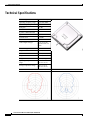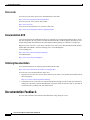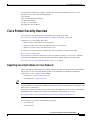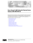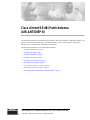
1
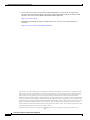
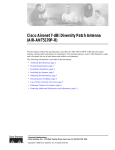
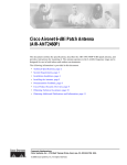
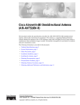
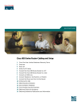
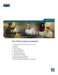
Cisco Aironet 9.5-dBi Patch Antenna
(AIR-ANT5195P-R)
This document outlines the specifications, describes the AIR-ANT5195P-R 9.5-dBi patch antenna, and
provides instructions for mounting it. The antenna operates in the 5-GHz frequency range and is
designed for use in both indoor and outdoor environments.
The following information is provided in this document.
•
Technical Specifications, page 2
•
System Requirements, page 3
•
Installation Guidelines, page 4
•
Installing the Antenna, page 5
•
Obtaining Documentation, page 11
•
Documentation Feedback, page 12
•
Cisco Product Security Overview, page 13
•
Obtaining Technical Assistance, page 14
•
Obtaining Additional Publications and Information, page 15
Corporate Headquarters:
Cisco Systems, Inc., 170 West Tasman Drive, San Jose, CA 95134-1706 USA
Copyright © 2005 Cisco Systems, Inc. All rights reserved.
Technical Specifications
Technical Specifications
Antenna type
2 x 2 Patch array
Operating frequency range
5150–5850 MHz
Nominal input impedance
50Ω
Peak gain
9.5 dBi
Polarization
Linear, vertical
E-plane 3-dB beamwidth
43
H-plane 3-dB beamwidth
50
Sidelobe level
<–20 dBc
Front-to-back ratio
>20 dB
Cable length and type
36 in. (91.4 cm)
Plenum rated, UV
stable
Connector type
RP-TNC Male
Length
5.1 in. (12.9 cm)
Width
5.1 in. (12.9 cm)
Height
1.0 in. (2.5 cm)
Weight
10 oz. (0.2 kg)
Operating temperature
range
–22 F to 158 F
(–30 C to 70 C)
Storage temperature range
–40 F to 185 F
(–40 C to 85 C)
E-Plane Pattern
H-Plane Pattern
Cisco Aironet 9.5-dBi Patch Antenna (AIR-ANT5195P-R)
2
78-16671-01
System Requirements
System Requirements
This antenna is designed for use with Cisco Aironet access points and bridges but can be used with any
5-GHz Cisco Aironet radio device that uses an RP-TNC connector.
Safety Precautions
Warning
Installation of this antenna near power lines is dangerous. For your safety, follow the installation
directions.
Warning
This warning symbol means danger. You are in a situation that could cause bodily injury. Before you
work on any equipment, be aware of the hazards involved with electrical circuitry and be familiar
with standard practices for preventing accidents.
Warning
In order to comply with international radio frequency (RF) exposure limits, dish antennas should be
located at a minimum of 8.7 inches (22 cm) or more from the bodies of all persons. Other antennas
should be located a minimum of 7.9 inches (20 cm) or more from the bodies of all persons.
Warning
Do not work on the system or connect or disconnect cables during periods of lightning activity.
Warning
This equipment must be grounded. Never defeat the ground conductor or operate the equipment in the
absence of a suitably installed ground conductor. Contact the appropriate electrical inspection
authority or an electrician if you are uncertain that suitable grounding is available.
Warning
Do not locate the antenna near overhead power lines or other electric light or power circuits, or
where it can come into contact with such circuits. When installing the antenna, take extreme care
not to come into contact with such circuits, as they may cause serious injury or death. For proper
installation and grounding of the antenna, please refer to national and local codes (e.g. U.S.:NFPA 70,
National Electrical Code, Article 810, in Canada: Canadian Electrical Code, Section 54).
Each year hundreds of people are killed or injured when attempting to install an antenna. In many of
these cases, the victim was aware of the danger of electrocution, but did not take adequate steps to avoid
the hazard.
For your safety, and to help you achieve a good installation, please read and follow these safety
precautions. They may save your life!
1.
If you are installing an antenna for the first time, for your own safety as well as others, seek
professional assistance. Your Cisco sales representative can explain which mounting method to use
for the size and type antenna you are about to install.
2.
Select your installation site with safety, as well as performance in mind. Remember: electric power
lines and phone lines look alike. For your safety, assume that any overhead line can kill you.
Cisco Aironet 9.5-dBi Patch Antenna (AIR-ANT5195P-R)
78-16671-01
3
Installation Guidelines
3.
Call your electric power company. Tell them your plans and ask them to come look at your proposed
installation. This is a small inconvenience considering your life is at stake.
4.
Plan your installation carefully and completely before you begin. Successful raising of a mast or
tower is largely a matter of coordination. Each person should be assigned to a specific task, and
should know what to do and when to do it. One person should be in charge of the operation to issue
instructions and watch for signs of trouble.
5.
When installing your antenna, remember:
a. Do not use a metal ladder.
b. Do not work on a wet or windy day.
c. Do dress properly—shoes with rubber soles and heels, rubber gloves, long sleeved shirt or
jacket.
6.
If the assembly starts to drop, get away from it and let it fall. Remember, the antenna, mast, cable,
and metal guy wires are all excellent conductors of electrical current. Even the slightest touch of any
of these parts to a power line complete an electrical path through the antenna and the installer: you!
7.
If any part of the antenna system should come in contact with a power line, don’t touch it or try to
remove it yourself. Call your local power company. They will remove it safely.
8.
If an accident should occur with the power lines call for qualified emergency help immediately.
Installation Guidelines
Because the antennas transmit and receive radio signals, they are susceptible to RF obstructions and
common sources of interference that can reduce throughput and range of the device to which they are
connected. Follow these guidelines to ensure the best possible performance:
•
Mount the antenna to take advantage its propagation characteristics. Mount it as high as possible
and oriented so that the cables are pointing down (towards the ground).
•
Keep the antenna away from metal obstructions such as heating and air-conditioning ducts, large
ceiling trusses, building superstructures, and major power cabling runs. If necessary, use a rigid
conduit to lower the antenna away from these obstructions.
•
The density of the materials used in a building’s construction determines the number of walls the
signal must pass through and still maintain adequate coverage. Consider the following before
choosing the location in which to install your antenna:
– Paper and vinyl walls have very little affect on signal penetration.
– Solid and pre-cast concrete walls limit signal penetration to one or two walls without degrading
coverage.
– Concrete and wood block walls limit signal penetration to three or four walls.
– A signal can penetrate five or six walls constructed of drywall or wood.
– A thick metal wall causes signals to reflect, causing poor penetration.
•
Install the antenna away from 5-GHz cordless phones. These products can cause signal interference
because they operate in the same frequency range as the device your antenna is connected to.
Cisco Aironet 9.5-dBi Patch Antenna (AIR-ANT5195P-R)
4
78-16671-01
Installing the Antenna
Site Selection
Before attempting to install your antenna, determine where you can best place the antenna for safety and
performance.
Follow these steps to determine a safe distance from wires, power lines, and trees.
Step 1
Measure the height of your antenna.
Step 2
Add this length to the length of your tower or mast and then double this total for the minimum
recommended safe distance.
Caution
If you are unable to maintain this safe distance, stop and get professional help.
Generally, the higher an antenna is above the ground, the better it performs. Good practice is to install
your antenna about 5 to 10 ft (1.5 to 3 m) above the roof line and away from all power lines and
obstructions. If possible, find a mounting place directly above your wireless device so that the lead-in
cable can be as short as possible.
Installing the Antenna
You can install the antenna on any flat vertical surface or on a mast using the mast mounting kit. An
articulated mast mounting kit is also available. Hardware for mounting the antenna on drywall is
provided. If you intend to install your antenna on another surface, you must provide the appropriate
hardware.
Tools and Equipment Required
An installation kit is shipped with the antenna and consists of the following hardware:
•
Four #8 x 1 -in. sheet metal screws
•
Four screw caps
•
Four screw cap washers
You need the following tools and equipment, which are not provided.
•
A #2 Phillips screwdriver
•
A drill
•
A 3/16-in. (4.8 mm) drill bit (for drywall installation; other surfaces may require a different size)
•
A pencil
•
A small mallet or hammer
The following sections contain typical procedures for installing the antenna on a vertical surface or a
mast. Your installation may vary. Before you begin, you may want to refer to Figure 1.
Cisco Aironet 9.5-dBi Patch Antenna (AIR-ANT5195P-R)
78-16671-01
5
Installing the Antenna
Mounting on a Vertical Surface
Follow these steps to mount your antenna on a vertical surface. This procedure describes mounting the
antenna on a drywall surface. If you are mounting the antenna on any other type of surface, your
procedure may vary slightly.
Step 1
Determine the location in which you will mount the antenna.
Step 2
Use the antenna as a template to mark the locations of the four mounting holes with a pencil.
Step 3
Use a drill and 3/16-in. (4.8 mm) drill bit to drill four holes at the locations you marked in Step 2.
Step 4
Start a plastic anchor into each hole.
Step 5
Use a mallet or small hammer to seat the anchors into the wall.
Step 6
Align the antenna’s mounting holes with the anchors.
Caution
The back of the antenna has an orientation marking. Make sure the antenna is mounted according to the
marking. If the antenna is not mounted properly, degraded performance could result.
Step 7
Put a screw cap washer onto a #8 screw and start the screw into each antenna mounting hole.
Step 8
Use a Phillips screwdriver to secure the antenna to the wall. Do not overtighten.
Step 9
Install the screw caps onto the screw cap washers.
Cisco Aironet 9.5-dBi Patch Antenna (AIR-ANT5195P-R)
6
78-16671-01
Installing the Antenna
Mounting on a Mast
The antenna can be mounted on a mast using an optional mast mounting kit as shown in Figure 1.
Figure 1
Optional Mast Mount
1
-20 u-bolt
4
Mounting plate
2
Support bracket
5
#8-32 x 1- machine screws and screw cap
washers
3
-in. flat washers and -20 nuts
6
Antenna cable
Follow these steps to mount the antenna on a mast.
Step 1
Place one -20 u-bolt around the mast, and place one support bracket on the u-bolt.
Step 2
Place the mounting plate on the u-bolt.
Step 3
Place two -inch flat washers and -20 nuts on the ends of the u-bolt. Tighten the nuts finger tight.
Step 4
Repeat steps 1 through 3 for the other u-bolt.
Step 5
Position the mounting plate on the mast in the direction the antenna should face and tighten the u-bolt
nuts with a 7/16-in. (11-mm) wrench.
Cisco Aironet 9.5-dBi Patch Antenna (AIR-ANT5195P-R)
78-16671-01
7
Installing the Antenna
Step 6
Position the antenna on the mounting plate.
Step 7
Place the screw cap washers onto the four #8-32 x 1- -in. machine screws.
Step 8
Install the screws through the antenna mounting plate and install the #8 nuts.
Step 9
Tighten the #8 screws and nuts with a #2 Phillips screwdriver and an 11/32-in. (9-mm) wrench.
Caution
Do not overtighten the nuts. You could damage the antenna.
Step 10
Install the screw caps onto the screw cap washers.
Step 11
Route the antenna cable to the wireless device.
Note
Cisco recommends grounding the antenna. See the “Grounding the Antenna” section on page 11
for details.
Cisco Aironet 9.5-dBi Patch Antenna (AIR-ANT5195P-R)
8
78-16671-01
Installing the Antenna
Installing the Articulated Mount
The antenna can also be mounted on an optional articulated mounting device as shown in Figure 2. The
articulated mount is used with the mast mount to provide a way to adjust the antenna elevation and
azimuth through a limited range.
Figure 2
Articulated Mount Details
1
u-bolt
6
Knuckle
2
Support bracket
7
Elevation adjustment bolt
3
-20 nut and flat washer
8
Stud nut
4
Articulated mount base
9
Stud
5
Azimuth adjustment nut and lockwasher
Cisco Aironet 9.5-dBi Patch Antenna (AIR-ANT5195P-R)
78-16671-01
9
Installing the Antenna
Figure 2 shows the articulated mount installed on a mast. You can also install it on any suitable flat
surface.
Follow these steps to install the articulated mount on a mast:
Step 1
Place one -20 u-bolt around the mast, and place one support bracket on the U-bolt.
Step 2
Place the articulated mounting base on the u-bolt.
Step 3
Place two -in. flat washers and -20 nuts on the ends of the u-bolt. Tighten the nuts finger tight.
Step 4
Repeat Steps 1 through 3 for the other u-bolt.
Step 5
Position the mounting plate on the mast in the direction the antenna should face and tighten the u-bolt
nuts with a 7/16-in. (11-mm) wrench.
Step 6
Use the elevation adjustment bolt to install the knuckle assembly on the articulated mount base.
Step 7
Install a lock washer and nut onto the elevation adjustment bolt. Tighten the nut finger tight.
Note
You may want to install the antenna on its antenna mounting plate before proceeding to the next
step. If so, skip Step 10 of this procedure and perform Steps 6 through 9 in the “Mounting on a
Mast” section on page 7
Step 8
Position the antenna mounting plate on the articulating mount stud.
Step 9
Start the stud nut onto the articulating mount stud. Tighten the nut hand tight. Be careful not to
overtighten the nut as the stud is made of plastic.
Step 10
Install the antenna on the antenna mounting plate.
Step 11
Use the azimuth and elevation adjustments to fine tune the antenna’s azimuth and elevation.
Step 12
When the antenna is properly adjusted, use a 9/16 in. wrench to tighten the azimuth and elevation
adjustment nuts. Do not overtighten.
Step 13
Route the antenna cable to the wireless device.
Note
Caution
Cisco recommends grounding the antenna. See the “Grounding the Antenna” section on page 11
for details.
If you install additional lengths of antenna cable, be sure to install a suitable strain relief. The antenna
may be damaged if you do not eliminate the extra weight of the cable. The antenna is not designed to
support the weight of a cable longer than the installed 3-ft (91.4 cm) cable.
Antenna Cable Information
Note
Coaxial cable loses efficiency as the frequency increases, resulting in signal loss. The cable
should be kept as short as possible because cable length also causes signal loss (the longer
the run, the greater the loss).
Cisco Aironet 9.5-dBi Patch Antenna (AIR-ANT5195P-R)
10
78-16671-01
Obtaining Documentation
Note
The antenna cable has a 0.5 in. (12.7 mm) bend radius. Sharply bending or crimping the cable may cause
a degredation in performance.
The antenna terminates with a RP-TNC plug after a short, 3-ft (0.91-m) cable. The mating connector to
the antenna is an appropriate RP-TNC jack. The connector on the opposite end will vary according to
the type of equipment used.
After the cable is attached to the antenna, make sure that the connections are sealed (if outdoors) to
prevent moisture and other weathering elements from affecting performance. Cisco recommends using
a coax seal (such as CoaxSeal) for outdoor connections. Silicone sealant or electrical tape are not
recommended for sealing outdoor connections.
Grounding the Antenna
Follow these steps to ground the antenna in accordance with national electrical code instructions.
Step 1
Use No. 10 AWG copper or No. 8 or larger copper-clad steel or bronze wire as ground wires for both
mast and lead-in. Securely clamp the wire to the bottom of the mast.
Step 2
Secure the lead-in wire to an antenna discharge unit and the mast ground wire to the building with
stand-off insulators spaced from 4 ft (1.2 m) to 8 ft (2.4 m) apart.
Step 3
Mount the antenna discharge unit as close as possible to where the lead-in wire enters the building.
Step 4
Drill a hole in the building’s wall as close as possible to the equipment to which you will connect the
lead-in cable.
Caution
There may be wires in the wall. Make sure your drilling location is clear of any obstructions or other
hazards.
Step 5
Pull the cable through the hole and form a drip loop close to where it enters the building.
Step 6
Thoroughly waterproof the lead-in area.
Step 7
Install a lightning arrestor.
Step 8
Connect the lead-in cable to the equipment.
Obtaining Documentation
Cisco documentation and additional literature are available on Cisco.com. Cisco also provides several
ways to obtain technical assistance and other technical resources. These sections explain how to obtain
technical information from Cisco Systems.
Cisco Aironet 9.5-dBi Patch Antenna (AIR-ANT5195P-R)
78-16671-01
11
Documentation Feedback
Cisco.com
You can access the most current Cisco documentation at this URL:
http://www.cisco.com/univercd/home/home.htm
You can access the Cisco website at this URL:
http://www.cisco.com
You can access international Cisco websites at this URL:
http://www.cisco.com/public/countries_languages.shtml
Documentation DVD
Cisco documentation and additional literature are available in a Documentation DVD package, which
may have shipped with your product. The Documentation DVD is updated regularly and may be more
current than printed documentation. The Documentation DVD package is available as a single unit.
Registered Cisco.com users (Cisco direct customers) can order a Cisco Documentation DVD (product
number DOC-DOCDVD=) from the Ordering tool or Cisco Marketplace.
Cisco Ordering tool:
http://www.cisco.com/en/US/partner/ordering/
Cisco Marketplace:
http://www.cisco.com/go/marketplace/
Ordering Documentation
You can find instructions for ordering documentation at this URL:
http://www.cisco.com/univercd/cc/td/doc/es_inpck/pdi.htm
You can order Cisco documentation in these ways:
•
Registered Cisco.com users (Cisco direct customers) can order Cisco product documentation from
the Ordering tool:
http://www.cisco.com/en/US/partner/ordering/
•
Nonregistered Cisco.com users can order documentation through a local account representative by
calling Cisco Systems Corporate Headquarters (California, USA) at 408 526-7208 or, elsewhere in
North America, by calling 1 800 553-NETS (6387).
Documentation Feedback
You can send comments about technical documentation to [email protected].
Cisco Aironet 9.5-dBi Patch Antenna (AIR-ANT5195P-R)
12
78-16671-01
Cisco Product Security Overview
You can submit comments by using the response card (if present) behind the front cover of your
document or by writing to the following address:
Cisco Systems
Attn: Customer Document Ordering
170 West Tasman Drive
San Jose, CA 95134-9883
We appreciate your comments.
Cisco Product Security Overview
Cisco provides a free online Security Vulnerability Policy portal at this URL:
http://www.cisco.com/en/US/products/products_security_vulnerability_policy.html
From this site, you can perform these tasks:
•
Report security vulnerabilities in Cisco products.
•
Obtain assistance with security incidents that involve Cisco products.
•
Register to receive security information from Cisco.
A current list of security advisories and notices for Cisco products is available at this URL:
http://www.cisco.com/go/psirt
If you prefer to see advisories and notices as they are updated in real time, you can access a Product
Security Incident Response Team Really Simple Syndication (PSIRT RSS) feed from this URL:
http://www.cisco.com/en/US/products/products_psirt_rss_feed.html
Reporting Security Problems in Cisco Products
Cisco is committed to delivering secure products. We test our products internally before we release them,
and we strive to correct all vulnerabilities quickly. If you think that you might have identified a
vulnerability in a Cisco product, contact PSIRT:
Tip
•
Emergencies — [email protected]
•
Nonemergencies — [email protected]
We encourage you to use Pretty Good Privacy (PGP) or a compatible product to encrypt any sensitive
information that you send to Cisco. PSIRT can work from encrypted information that is compatible with
PGP versions 2.x through 8.x.
Never use a revoked or an expired encryption key. The correct public key to use in your correspondence
with PSIRT is the one that has the most recent creation date in this public key server list:
http://pgp.mit.edu:11371/pks/lookup?search=psirt%40cisco.com&op=index&exact=on
In an emergency, you can also reach PSIRT by telephone:
•
1 877 228-7302
•
1 408 525-6532
Cisco Aironet 9.5-dBi Patch Antenna (AIR-ANT5195P-R)
78-16671-01
13
Obtaining Technical Assistance
Obtaining Technical Assistance
For all customers, partners, resellers, and distributors who hold valid Cisco service contracts, Cisco
Technical Support provides 24-hour-a-day, award-winning technical assistance. The Cisco Technical
Support Website on Cisco.com features extensive online support resources. In addition, Cisco Technical
Assistance Center (TAC) engineers provide telephone support. If you do not hold a valid Cisco service
contract, contact your reseller.
Cisco Technical Support Website
The Cisco Technical Support Website provides online documents and tools for troubleshooting and
resolving technical issues with Cisco products and technologies. The website is available 24 hours a day,
365 days a year, at this URL:
http://www.cisco.com/techsupport
Access to all tools on the Cisco Technical Support Website requires a Cisco.com user ID and password.
If you have a valid service contract but do not have a user ID or password, you can register at this URL:
http://tools.cisco.com/RPF/register/register.do
Note
Use the Cisco Product Identification (CPI) tool to locate your product serial number before submitting
a web or phone request for service. You can access the CPI tool from the Cisco Technical Support
Website by clicking the Tools & Resources link under Documentation & Tools. Choose Cisco Product
Identification Tool from the Alphabetical Index drop-down list, or click the Cisco Product
Identification Tool link under Alerts & RMAs. The CPI tool offers three search options: by product ID
or model name; by tree view; or for certain products, by copying and pasting show command output.
Search results show an illustration of your product with the serial number label location highlighted.
Locate the serial number label on your product and record the information before placing a service call.
Submitting a Service Request
Using the online TAC Service Request Tool is the fastest way to open S3 and S4 service requests. (S3
and S4 service requests are those in which your network is minimally impaired or for which you require
product information.) After you describe your situation, the TAC Service Request Tool provides
recommended solutions. If your issue is not resolved using the recommended resources, your service
request is assigned to a Cisco TAC engineer. The TAC Service Request Tool is located at this URL:
http://www.cisco.com/techsupport/servicerequest
For S1 or S2 service requests or if you do not have Internet access, contact the Cisco TAC by telephone.
(S1 or S2 service requests are those in which your production network is down or severely degraded.)
Cisco TAC engineers are assigned immediately to S1 and S2 service requests to help keep your business
operations running smoothly.
To open a service request by telephone, use one of the following numbers:
Asia-Pacific: +61 2 8446 7411 (Australia: 1 800 805 227)
EMEA: +32 2 704 55 55
USA: 1 800 553-2447
For a complete list of Cisco TAC contacts, go to this URL:
http://www.cisco.com/techsupport/contacts
Cisco Aironet 9.5-dBi Patch Antenna (AIR-ANT5195P-R)
14
78-16671-01
Obtaining Additional Publications and Information
Definitions of Service Request Severity
To ensure that all service requests are reported in a standard format, Cisco has established severity
definitions.
Severity 1 (S1)—Your network is “down,” or there is a critical impact to your business operations. You
and Cisco will commit all necessary resources around the clock to resolve the situation.
Severity 2 (S2)—Operation of an existing network is severely degraded, or significant aspects of your
business operation are negatively affected by inadequate performance of Cisco products. You and Cisco
will commit full-time resources during normal business hours to resolve the situation.
Severity 3 (S3)—Operational performance of your network is impaired, but most business operations
remain functional. You and Cisco will commit resources during normal business hours to restore service
to satisfactory levels.
Severity 4 (S4)—You require information or assistance with Cisco product capabilities, installation, or
configuration. There is little or no effect on your business operations.
Obtaining Additional Publications and Information
Information about Cisco products, technologies, and network solutions is available from various online
and printed sources.
•
Cisco Marketplace provides a variety of Cisco books, reference guides, and logo merchandise. Visit
Cisco Marketplace, the company store, at this URL:
http://www.cisco.com/go/marketplace/
•
Cisco Press publishes a wide range of general networking, training and certification titles. Both new
and experienced users will benefit from these publications. For current Cisco Press titles and other
information, go to Cisco Press at this URL:
http://www.ciscopress.com
•
Packet magazine is the Cisco Systems technical user magazine for maximizing Internet and
networking investments. Each quarter, Packet delivers coverage of the latest industry trends,
technology breakthroughs, and Cisco products and solutions, as well as network deployment and
troubleshooting tips, configuration examples, customer case studies, certification and training
information, and links to scores of in-depth online resources. You can access Packet magazine at
this URL:
http://www.cisco.com/packet
•
iQ Magazine is the quarterly publication from Cisco Systems designed to help growing companies
learn how they can use technology to increase revenue, streamline their business, and expand
services. The publication identifies the challenges facing these companies and the technologies to
help solve them, using real-world case studies and business strategies to help readers make sound
technology investment decisions. You can access iQ Magazine at this URL:
http://www.cisco.com/go/iqmagazine
Cisco Aironet 9.5-dBi Patch Antenna (AIR-ANT5195P-R)
78-16671-01
15
Obtaining Additional Publications and Information
•
Internet Protocol Journal is a quarterly journal published by Cisco Systems for engineering
professionals involved in designing, developing, and operating public and private internets and
intranets. You can access the Internet Protocol Journal at this URL:
http://www.cisco.com/ipj
•
World-class networking training is available from Cisco. You can view current offerings at
this URL:
http://www.cisco.com/en/US/learning/index.html
CCSP, CCVP, the Cisco Square Bridge logo, Follow Me Browsing, and StackWise are trademarks of Cisco Systems, Inc.; Changing the Way We
Work, Live, Play, and Learn, and iQuick Study are service marks of Cisco Systems, Inc.; and Access Registrar, Aironet, ASIST, BPX, Catalyst,
CCDA, CCDP, CCIE, CCIP, CCNA, CCNP, Cisco, the Cisco Certified Internetwork Expert logo, Cisco IOS, Cisco Press, Cisco Systems, Cisco
Systems Capital, the Cisco Systems logo, Cisco Unity, Empowering the Internet Generation, Enterprise/Solver, EtherChannel, EtherFast,
EtherSwitch, Fast Step, FormShare, GigaDrive, GigaStack, HomeLink, Internet Quotient, IOS, IP/TV, iQ Expertise, the iQ logo, iQ Net Readiness
Scorecard, LightStream, Linksys, MeetingPlace, MGX, the Networkers logo, Networking Academy, Network Registrar, Packet, PIX, Post-Routing,
Pre-Routing, ProConnect, RateMUX, ScriptShare, SlideCast, SMARTnet, StrataView Plus, TeleRouter, The Fastest Way to Increase Your Internet
Quotient, and TransPath are registered trademarks of Cisco Systems, Inc. and/or its affiliates in the United States and certain other countries.
All other trademarks mentioned in this document or Website are the property of their respective owners. The use of the word partner does not imply
a partnership relationship between Cisco and any other company. (0502R)
Copyright © 2005 Cisco Systems, Inc. All rights reserved.
Printed in the USA on recycled paper containing 10% postconsumer waste.
Cisco Aironet 9.5-dBi Patch Antenna (AIR-ANT5195P-R)
16
78-16671-01