1
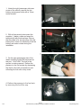
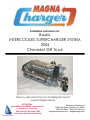
Installation Instructions for:
Radix
INTERCOOLED SUPERCHARGER SYSTEM
2004
Chevrolet SSR Truck
Step-by-step instructions for installing the best in
supercharger systems.
ATTENTION!
Your MAGNA CHARGER intercooler kit
is sensitive to corrosion!
Take care of if by using 50/50
anti-freeze with de-ionized water.
89-89-60-010 Rev H
Magnuson Products Inc
1990 Knoll Drive, Ventura, CA. 93003
(805) 289-0044 * (805) 677-4897 fax
magnusonproducts.com * magnacharger.com
INSTALLATION MANUAL
Magna Charger
Radix Intercooled Supercharger System
GM 4.8, 5.3 & 6.0 liter engines
We encourage you to read this manual thoroughly before you begin work, for a few reasons:
A quick parts check to make certain your kit is complete (See shipper parts list in this manual). If you
discover shipping damage or shortage, please call our office immediately.
Take a look at exactly what you are going to need in terms of tools, time, and experience.
Review our limited warranty with care.
Make sure to have 91 or higher octane fuel in the tank.
When unpacking the supercharger kit DO NOT lift the supercharger assembly by the black plastic
bypass actuator. This is pre-set from the factory and can be altered if used as a lifting point!
Tools Required
!
!
!
!
!
!
!
!
!
!
!
!
!
!
!
7/12
Safety glasses
Metric wrench set
1/4” drill bit
1/4”, 3/8”, & 1/2” drive metric socket set ( standard and deep )
8mm hex (Allen) wrench
3/8” and 1/2” drive foot pound and inch pound torque wrenches
Belt tensioner wrench or 1/2” breaker bar
7/32” socket
Drill and 5/16” drill bit
Phillips and flat head screwdrivers
Fuel quick disconnect tools (included in kit)
E5 internal Torx socket
Small or angled 3/8” drill motor
Drain pan
Compressed air
Page 2
2003-2004 Chevy SSR Supercharger Installation Instructions
magnacharger.com
Important
Our Magna Charger kits are designed for stock engines, with stock components, in good mechanical
condition only. Installation on worn or damaged engines is not recommended and may result in engine
failure, for which we naturally can't be responsible . Magna Charger is not responsible for the engine or
consequential damages.
Aftermarket engine re-calibration devices that modify fuel and spark curve (i.e.. programmers) are not
recommended and may cause engine damage or failure. If you have any questions, call us!
Caution: Relieve the fuel system pressure before servicing fuel system components in
order to reduce the risk of fire and personal injury. After relieving the system pressure, a small amount
of fuel may be released when servicing the fuel lines or connections. In order to reduce the risk of
personal injury, cover the regulator and fuel line fittings with a shop towel before disconnecting. This
will catch any fuel that may leak out. Place the towel in an approved container when the job is
complete, and of course, no smoking.
Magna Charger strongly recommends the following:
]
]
]
]
]
Clean your engine compartment before starting any engine disassembly.
You must have a clean fuel filter - check and replace as needed before installation.
You must have a clean air filter - replace every 10,000 miles.
OE type / Stock spark plugs and stock plug gap is recommended.
Start with and use only 91 octane fuel or higher.
After you finish your installation and road test your vehicle, please fill out and
mail the limited warranty card, so we can add you to our files (this is important
for your protection).
Please remember to follow all safety rules that apply when working, including:
!
!
!
7/12
Wear eye protection at all times.
Do not work on a hot engine.
Be careful around fuel - use shop towels to catch any spills and dispose of
towels properly.
Page 3
2003-2004 Chevy SSR Supercharger Installation Instructions
magnacharger.com
1. Under the right (passenger side) rear
corner of the vehicle, remove the two
battery access panel bolts with a 10mm
socket wrench.
2. With a 8mm wrench disconnect the
negative (-) battery cable and wrap the
terminal end with electrical tape. Ensure
that the cable is far enough away from the
battery that it does not accidently touch the
battery and make contact during the
installation.
3. On the right (passenger) side of the
intake manifold, locate the fuel pressure
test port. CAUTION! The fuel in the
system is under pressure! Relieve the
pressure in the fuel system by depressing
the check valve with a screwdriver and
collecting the fuel with a shop towel.
4. Relieve the pressure in the fuel tank
by removing the fuel filler cap.
7/12
Page 4
2003-2004 Chevy SSR Supercharger Installation Instructions
magnacharger.com
5. Here is the new fuel pump and its
components. Note the male and female fuel
lines.
6. On the back face of the transmission
cross member, unclip the electrical
connector and gray harness clip from their
mounting positions.
7. Measuring 1/2” up from the bottom edge
and 2” over from the connector hole, mark
and drill two 1/4” holes 3” apart.
Connector
hole
8. Using the two mounting clamps and self
tapping screws, mount the fuel pump to the
cross member using a 10mm socket
wrench.
Note that the end of the pump with the
electrical terminals is pointed towards the
left (driver) side.
7/12
Page 5
2003-2004 Chevy SSR Supercharger Installation Instructions
magnacharger.com
9. On the front surface of the fuel tank,
facing the transmission cross member is
the vehicle fuel filter.
Fuel filter
10. Squeeze the blue release triggers to
release the fuel line connector on the “OUT”
nipple of the filter.
11. Remove the blue release trigger from
the “OUT” nipple on the fuel filter.
12. Install the blue release trigger on the
male pump connector. Insert the male fuel
line into the female connector previously
removed from the “OUT” nipple on the filter.
7/12
Page 6
2003-2004 Chevy SSR Supercharger Installation Instructions
magnacharger.com
13. Install the female fuel line from the
pump on the “OUT” nipple of the fuel filter.
Female line
14. Here is the completed fuel line
connections at the fuel filter. Use the tie
straps supplied to secure the fuel lines as
necessary.
Male line
Pump connections
+ Power connection
15. Here is the wiring harness for the new
fuel pump. Note the different connections.
-Ground connection
16. On the pump connections, strip the
insulation back 1/4” and crimp on the ring
terminals supplied.
7/12
Page 7
2003-2004 Chevy SSR Supercharger Installation Instructions
magnacharger.com
17. Install the pump connections on the
pump terminals with a 8mm wrench.
Ensure that the Red wire is on the positive
(+) terminal and the black wire on the
negative (-) terminal. Route the remainder
of the harness forward along the frame and
up to the Fuse-Relay Center. The remaining
connections will be completed in a later
step.
18. When the engine is cool, remove the
radiator reservoir cap. Do not remove the
cap if the engine is still hot or serious
injury may result.
19. Remove the SSR badge from the
engine cover with a straight blade
screwdriver by gently prying it up on the
front edge.
20. Remove the engine cover’s three
fasteners with a 8mm socket wrench.
7/12
Page 8
2003-2004 Chevy SSR Supercharger Installation Instructions
magnacharger.com
21. Remove the engine cover completely,
as it and the SSR badge will not be reused.
22. Loosen the air filter bellows clamp and
the Mass Air Flow meter (MAF) clamp with
a 8mm nut driver.
MAF
Clamp
23. Unplug the Mass Air Flow meter (MAF)
connector by pulling out the gray release
trigger and the squeezing the connector.
24. Remove the two plastic push-lock
rivets from the air filter apron. Do this by
gently prying the center of the rivet up with
a straight blade screwdriver and then
removing the rivets completely.
7/12
Page 9
2003-2004 Chevy SSR Supercharger Installation Instructions
magnacharger.com
25. Remove the nuts and washers from
each side of the air filter apron with a 10mm
socket wrench.
26. Remove the air filter apron.
27. Remove the two remaining bolts
securing the air filter with a 10mm socket
wrench.
28. Remove the air filter assembly
complete and then separate the MAF and
bellows from the air filter cover.
7/12
Page 10
2003-2004 Chevy SSR Supercharger Installation Instructions
magnacharger.com
29. As it will be necessary to drain the
cooling system and most SSR trucks have
no drain on the radiator, loosen the two
bolts that secure the thermostat assembly
with a 10mm socket wrench. Catch the
coolant in a drain pan for reuse. Re-tighten
the thermostat bolts after draining is
complete.
30. Using a long pair of pliers, remove the
coolant hoses from the bottom of the
throttle body.
31. Remove the PCV vent hose from the
intake manifold on passenger side.
32. Open the large electrical harness
retainer clip, then using a 10mm socket
wrench remove the bolts holding the plastic
wire harness retainer to the intake manifold.
7/12
Page 11
2003-2004 Chevy SSR Supercharger Installation Instructions
magnacharger.com
33. Using a 10mm socket wrench, remove
the three bolts that fasten the cover support
bracket from the top of the intake manifold.
34. Disconnect the eight fuel injector
connections by gently pulling up on the gray
plastic release trigger on the connector and
then pulling firmly on the connector itself.
Disconnect the coil pack connector and
then the four wire harness clips that secure
the harness to the right side of the engine.
COIL
CONNECTOR
HARNESS CLIP
INJECTOR
CONNECTOR
35. Disconnect electric throttle control
(ETC) connector from the throttle body by
removing the gray plastic locking tab first,
then squeeze and pull free the ETC
connector itself.
36. At the rear of the of the intake manifold
disconnect the Manifold Absolute Pressure
(MAP) sensor connector by gently raising
the gray plastic retaining clip and then pull
free the connector.
7/12
Page 12
2003-2004 Chevy SSR Supercharger Installation Instructions
MAP
Connector
magnacharger.com
Knock
connector
37. Disconnect the engine knock sensor
connector and steel-mounting clip from the
intake manifold by prying it free with a small
screwdriver. Next gently raise the black
plastic retaining clip and then pull free the
connector from the harness.
EVAP Connector
38. Disconnect the evaporative purge
solenoid EVAP connector by raising the
black plastic retaining clip and then pull free
the connector itself.
39. Disconnect the Air Conditioning (A/C)
Pressure connector from the pressure
switch and from the clip on the cylinder
head.
40. Lift the electrical harness from the top
of the engine and set off to the left (drivers)
side.
7/12
Page 13
2003-2004 Chevy SSR Supercharger Installation Instructions
magnacharger.com
41. Disconnect the EVAP vent tube from
the solenoid by squeezing the retainer, then
release the tube from the solenoid. Follow
the same procedure on the other end of the
vent tube at the firewall and remove the
tube from the vehicle.
42. Remove the Positive Crankcase
Vacuum (PCV) hose from the intake
manifold on driver side.
43. Remove the power brake hose and
check valve from the brake booster.
44. With the fuel line disconnect tool
supplied, remove the fuel line from the fuel
rail. Caution! The system may be under
pressure. Avoid open flame or other
sources of ignition.
7/12
Page 14
2003-2004 Chevy SSR Supercharger Installation Instructions
magnacharger.com
45. Using a 8mm socket wrench remove
the ten intake manifold bolts.
46. Carefully remove the intake manifold
assembly and set aside.
47. Using a vacuum cleaner, remove any
dirt or debris from the intake port area. (Be
careful not to get any dirt in the intake
ports).
48. Cover the intake ports with tape or
clean rags to keep dirt and objects from
entering the engine. (Remember, be clean).
7/12
Page 15
2003-2004 Chevy SSR Supercharger Installation Instructions
magnacharger.com
49. Using a 10mm socket wrench remove
the two coolant vent pipe bolts.
50. Remove the vent pipe assembly.
(Make sure that the o-ring gaskets did not
stick to the cylinder heads, if so remove
them).
51. Using a 15mm tensioner wrench or
breaker bar, remove the stock serpentine
belt from the vehicle. The belt will not be
reused.
52. Using a 15mm socket wrench remove
the three bolts holding the factory belt
tensioner to the bracket and remove the
tensioner.
7/12
Page 16
2003-2004 Chevy SSR Supercharger Installation Instructions
magnacharger.com
53. Disconnect the positive (+) battery
cable from the back of the alternator with a
10mm wrench.
54. Disconnect the positive (+) battery
cable from the back of the alternator with a
10mm wrench. Use a 15mm socket wrench
remove the two bolts holding the alternator
to the alternator bracket and then remove
the alternator.
55. It will be necessary to make clearance
on the alternator mount casting for the new
manifold to fit properly. The new manifold
should not touch the alternator mount.
These modifications can be easily done
with the mount in place.
Remove this
material
56. For clarity this mount is shown
removed from the engine. Using a marking
pen and a straight edge, mark a line as
shown on the top surface of the of the
alternator mount. Start the line at the left
(driver’s) rear corner of the idler mount and
then to the right rear corner of the alternator
mount. Continue the line at an angle for a
distance of about 1-1/4” to the back edge of
the casting behind the alternator mount.
Using a suitable grinder and eye protection,
remove the material up to the line.
7/12
Page 17
2003-2004 Chevy SSR Supercharger Installation Instructions
magnacharger.com
57. On the back surface of the alternator
mount, remove the shaded area as shown.
58. Here is what your finished alternator
mount should look like.
59. Using the stock bolts removed in step
72 install the new coolant vent pipe
supplied. Ensure that the o-ring seals are
installed correctly. Torque the bolts with a
torque wrench and 10mm socket to 106 lbin.
60. Using the supplied 3/8” hose, connect
a 15” length to the PCV valve as shown and
lay the other end of the hose off to the
drivers side, out of the way. (To be
connected in a later step.)
7/12
Page 18
2003-2004 Chevy SSR Supercharger Installation Instructions
magnacharger.com
61. On the engine valley cover, remove the
two black rubber knock sensor covers by
gently prying them up using a small straight
blade screwdriver. Disconnect the electrical
connectors by squeezing the side of plugs
with a pair of long jaw or needle nose pliers
and pulling up.
62. Remove the two knock sensors by
using a ratchet and a deep 22mm socket.
63. Remove the engine valley cover and
gasket by removing the ten bolts with a
ratchet and 13mm socket.
64. The gasket will be reused, the original
valley cover and bolts will not. Inspect the
gasket for any damage and then reinstall,
note that it will only fit correctly in one
position.
7/12
Page 19
2003-2004 Chevy SSR Supercharger Installation Instructions
magnacharger.com
65. Install the new engine valley cover and
flathead bolts supplied with a 5mm Allen
socket and torque the bolts to 18 lb-ft.
Insert the six O-rings in the recesses in the
new valley cover.
Orings
66. Reinstall the knock sensors and torque
thm to15 lb ft. Reattach the electrical
connectors by pushing the plug down firmly
until a “click” is heard. Before installing the
covers, apply a bead of the silicone
adhesive supplied to the side of each of the
covers. Finally push the covers back into
place.
67. Remove the existing tape from the
knock sensor wires so that they can be
installed on the grooves in the top of the
new valley cover. Use some tape to hold
the wires in place temporarily, and then use
some of the silicone adhesive to retain the
wires permanently.
68. Using a 13mm wrench remove the bolt
securing the attachment clip for the two fuel
lines.
7/12
Page 20
2003-2004 Chevy SSR Supercharger Installation Instructions
magnacharger.com
69. Remove the steel bracket on the rear
of the left cylinder head with a 15mm
wrench. The bracket will not be reused.
70. Remove the two bolts securing the
firewall seam cover from the firewall with a
10mm socket wrench.
71. From the hole nearest the center of the
seam cover, measure over 1” and make a
line across the cover.
72. Cut the seam cover in two pieces with
a suitable saw.
7/12
Page 21
2003-2004 Chevy SSR Supercharger Installation Instructions
magnacharger.com
73. Reinstall the longer piece of the seam
cover with its fasteners in the original
location.
Bend here
74. Remove the upper radiator hose at the
upper water pump outlet.
75. The original water pump outlet tube will
need to be replaced. Remove the outlet by
cutting it off. Use a suitable hacksaw and
cut it off approximately 1” above the water
pump casting.
76. Remove the remaining stub of the
outlet in the pump casting by collapsing it
within itself. The object is to reduce the
diameter of the stub by collapsing it not to
cut it. Use a dull chisel or wide drift with a
hammer to drive one side of the stub across
and down to the other side. Take care not
to damage or scratch the outlet bore of the
water pump casting.
7/12
Page 22
2003-2004 Chevy SSR Supercharger Installation Instructions
magnacharger.com
77. Use a pair of pliers to pull the collapsed
stub straight up and out. Do not twist the
stub as you pull it out, as this will scratch
the outlet bore of the water pump casting.
Retainer
78. Here are the new components for the
water pump outlet and tensioner assembly.
Water
outlet
Bolt
Idler
pulley
Base
Tensioner
O-rings
Outlet base
79. In the original tensioner location, mount
the new outlet base with the new tensioner
assembly on top of it. Use only the two
long mounting bolts, the third shorter bolt
will not be reused. Replace the factory idler
pulley mounted on the alternator bracket
with the new pulley supplied. Tighten the
mounting bolts and with a 15mm socket
and torque wrench to 40 lb-ft.
80. Install the two O-rings supplied into the
grooves on the new water pump outlet.
O-rings
7/12
Page 23
2003-2004 Chevy SSR Supercharger Installation Instructions
magnacharger.com
81. Using some of the grease supplied,
gently install the new outlet in to the bore of
the water pump casting.
82. Install the outlet retainer and
8 x 20mm bolt into the tensioner base. Do
not tighten the retainer bolt yet as final
positioning will be done in a later step.
Tighten the bolt finger tight for now.
83. Install the upper radiator hose and
clamp onto the new water pump outlet.
84. Remove the stock MAP sensor from
the stock intake manifold by pulling back on
the two tabs and lifting the sensor out.
Ensure that the orange MAP sensor seal is
not damaged, as it will be used.
7/12
Page 24
2003-2004 Chevy SSR Supercharger Installation Instructions
magnacharger.com
85. Put some lubricant on the MAP sensor
seal and press the MAP sensor into the
provided hole in the supercharger manifold
as shown.
86. Using a 4mm Allen wrench, install the
MAP sensor retaining clip with the provided
6mm button head screw as shown.
87. Install the new intake manifold gaskets
supplied onto the recesses in the manifold
face. Ensure that the gaskets are fully
seated in the manifold face.
88. Remove the stock fuel pressure
regulator from the fuel rail by disconnecting
the vacuum hose, pulling off the spring clip
and pulling the regulator out. Be careful not
to lose any of the small O-rings on the
regulator.
7/12
Page 25
2003-2004 Chevy SSR Supercharger Installation Instructions
magnacharger.com
89. Make sure that the two O-rings and the
screen filter is complete as shown.
90. Using a small amount of grease or oil
lubricate the two O-rings on the fuel
pressure regulator and push it into the new
supplied fuel manifold as shown.
91. Using a pair of C-clip pliers install the
new supplied C-clip into the fuel manifold as
shown. (Make sure that the clip seats into
the machined grove in the manifold.)
92. Apply a small amount of grease to the
new supplied fuel manifold O-ring and set in
the machined recessed area on the new
driver’s side fuel rail as shown.
7/12
Page 26
2003-2004 Chevy SSR Supercharger Installation Instructions
magnacharger.com
93. Install the assembled fuel manifold to
the drivers side fuel rail using the two new
supplied 6mm bolts. Using a 10mm socket
torque wrench the bolts to 106 lb-in. (Be
careful not to pinch the O-ring.)
94. Install the small vacuum hose from the
nipple on the fuel regulator to the nipple at
the rear of the manifold.
95. Using a 10mm socket wrench remove
the stock throttle body from the stock intake
manifold. Next, using a # 5 internal Torx
socket remove the three mounting studs
from the stock intake manifold.
96. Install the three studs removed in the
previous step into the new supercharger
inlet manifold using a # 5 internal Torx
socket and wrench.
7/12
Page 27
2003-2004 Chevy SSR Supercharger Installation Instructions
magnacharger.com
97. Using the supplied gasket, mount the
throttle body using the original nuts.
Tighten them securely.
98. Remove tape from the cylinder head
port faces and lubricate the surfaces with
silicone spray or soapy water. Do not use
any pertroleum based products that could
damage the port gaskets.
99. Using a assistant, carefully lower the
supercharger and manifold assembly into
place. Ensure that the two metal fuel lines
at the firewall are out of the way. Do not
use the black bypass canister to lift the
assembly by or damage will result. Use
care not to damage the port gaskets.
100. Remove the split-looms that support
some of the manifold to cylinder head bolts.
Start all ten bolts by hand to ensure proper
alignment of the manifold.
7/12
Page 28
2003-2004 Chevy SSR Supercharger Installation Instructions
magnacharger.com
101. Torque all ten bolts that secure the
manifold to the cylinder heads gradually
and evenly to a torque of 89 lb-in. Use a
10mm socket and torque wrench.
102. Push the fuel line connectors on to
the fuel manifold. Ensure that the fuel line
is pushed all the way on. Pull on the
connectors to check that they are secure,
you should not be able to remove the
connector unless you use the removal tool.
103. Remove the EVAP solenoid from the
stock manifold with a 10mm socket wrench.
Mounting bracket
104. Install the purge solenoid on the new
mounting bracket with its original mounting
bolt tightened securely.
7/12
Page 29
2003-2004 Chevy SSR Supercharger Installation Instructions
magnacharger.com
105. From the length of 3/8” hose, cut a 9”
length and insert one end on the large barb
of the mounting bracket. On the small barb
of the solenoid insert one end of the 15”
length of 5/16” hose and secure it with a
with a #4 clamp.
#4 clamp
3/8” hose
EVAP
Connector
106. Insert the EVAP connector supplied in
the remaining end of the 5/16” hose and
secure it with a #4 clamp.
3/8” “T”
Fitting
107. From the remaining length of 3/8”
hose cut a 5” length and install it on one
barb of the new 3/8” “T” connector.
Connect the hose previously installed on
valve cover in step 59 to the opposite barb.
Attach the purge solenoid hose to the lower
barb.
108. Here is the EVAP and PCV hose
connections on the left side of the
engine.
#4 clamp
5/16”
Hose to PCV connection
at valve cover
Purge solenoid
Barb on inet
manifold
PCV on
valve cover
EVAP at
firewall
#4 clamp
3/8”
hose
7/12
5/16” hose
Page 30
2003-2004 Chevy SSR Supercharger Installation Instructions
#4 clamp
5/16” hose
magnacharger.com
Coil pack
connector
109. Mount the solenoid bracket on the
stud located below the coil pack connector
on the left side of the engine using the
supplied nut. Tighten the nut securely with
a 10mm socket wrench.
Stud
and
nut
Purge
solenoid
110. Install the EVAP/PCV hose on the
middle barb of the inlet manifold. Connect
the new EVAP connector to the EVAP line
behind the engine on the firewall.
111. From the remaining length of 3/8”
hose, cut two 6” lengths and assemble
them to the 3/8” elbow fitting to make the
PCV inlet hose. One end will attach to the
right valve cover barb and the other to
upper barb on the inlet manifold behind the
throttle body.
Right valve
cover PCV Barb
Inlet barb
3/8” Elbow
112. The PCV inlet barb is located on the
right valve cover under the coil pack
bracket. Attach the end of the new inlet
hose here.
7/12
PCV inlet barb
Page 31
2003-2004 Chevy SSR Supercharger Installation Instructions
magnacharger.com
Inlet barb
113. Pass the PCV inlet hose under the
supercharger drive shaft and install the
remaining end of the inlet hose to the upper
barb on the inlet manifold. Note the
position of the elbow fitting, its purpose is to
ensure that the inlet hose does not contact
the rotating supercharger drive shaft.
Elbow fitting
114. Insert the new vacuum check valve
into the end of the new 11/32” Vacuum
hose.
115. Install the new check valve into the
brake booster. Connect the other end of
the vacuum hose to the remaining barb on
the side of the inlet manifold.
116. Using a 10mm socket wrench, remove
the two bolts that secure the air filter cover
to the air box assembly.
7/12
Page 32
2003-2004 Chevy SSR Supercharger Installation Instructions
magnacharger.com
117. Inspect the air filter, it should replaced
every 10,000 miles.
118. Assemble the air box with the new
filter cover supplied.
119. Secure the new filter cover with the
original fasteners and a 10mm wrench.
120. Install the MAF and bellows to the
new air filter cover.
7/12
Page 33
2003-2004 Chevy SSR Supercharger Installation Instructions
magnacharger.com
121. Reinstall the bellows to the throttle
body and then reattach the air filter box and
its apron to the vehicle.
122. Here is the intercooler reservoir and
its mounting hardware.
Lower mounting tab
123. Assemble the reservoir to the
mounting bracket using the two 6 x 20mm
bolts and nuts supplied. Position the
bracket so that the lower mounting tab is
pointing away from the reservoir. Tighten
securely with a 10mm socket wrench.
124. Remove the bolt and washer that
secures the front mounting foot of the
radiator coolant tank. Insert the lower
mounting tab of the intercooler reservoir
under the foot of the coolant tank and
reinstall the bolt and washer. Tighten the
bolt securely with a 10mm socket wrench.
7/12
Coolant tank
mounting foot
Lower
mounting tab
Page 34
2003-2004 Chevy SSR Supercharger Installation Instructions
magnacharger.com
125. Here is the installed intercooler
reservoir and bracket on the vehicle.
126. Here is the intercooler heat exchanger
and its mounting components.
127. Install two of the round-headed
carriage bolts supplied into both channels
on the sides of the heat exchanger. The
square portion of the bolt shaft must be
aligned with the side of the channel.
128. Align the bolts with the holes in the
vertical mounting brackets.
7/12
Page 35
2003-2004 Chevy SSR Supercharger Installation Instructions
magnacharger.com
129. Torque the mounting nuts to 18 ft-lbs
with a 13mm torque wrench.
130. Install the cross member to the
vertical brackets with the 8 x 20mm bolts
supplied. Tighten securely with a 13mm
wrench.
131. Here is the completed heat exchanger
ready for installation. Note: That the heat
exchanger barbs and long end of the cross
member are on the right side.
8 X 20mm
bolt
Right
side
132. Install the heat exchanger assembly
by sliding the complete assembly up from
underneath the vehicle between the power
steering cooler and the A/C condenser.
The nose of the vehicle has been removed
for clarity only. You do not have to remove
the nose to install the heat exchanger.
7/12
Page 36
2003-2004 Chevy SSR Supercharger Installation Instructions
magnacharger.com
133. Using a 15mm wrench, remove the
mounting bolts on both sides of the vehicle
that are located below the power steering
cooler bracket. Slide the heat exchanger
up into position and then attach its
mounting bracket with the original mounting
bolts.
Mounting bolt
134. Here is the mounting bolt on the right
side of the vehicle. Note: That the heat
exchanger barbs must be pointing to this
side.
Mounting bolt
135. To create a space for the coolant lines
to pass through the heat exchanger, you
must remove the molded foam block
located between the side of the radiator and
the body. To remove the molded block,
push it free with a straight blade
screwdriver between the fender and the
radiator support.
136. After pushing the molded foam block,
pull it out from the engine compartment.
The foam block will not be reused.
7/12
Page 37
2003-2004 Chevy SSR Supercharger Installation Instructions
magnacharger.com
137. Removing the molded foam block
creates a opening between the radiator and
the fender well for the intercooler coolant
lines to pass. The line from the pump to the
heat exchanger and from the heat
exchanger to the coolant manifold will pass
through this opening.
Intercooler lines
pass through here
138. Here is the intercooler pump,
mounting clamp, hardware, wiring and
reservoir to pump hose.
139. The intercooler pump will mount in the
right side of the engine compartment next
to the battery cable junction box. Note: The
elongated hole in the panel.
Junction box
Pump
Hole
Mounting bolt
and clamp
Pump
140. From underneath the vehicle on the
right side locate the elongated hole.
Approximately 1” back from the hole drill a
1/4” hole to mount the pump. Place the
mounting clamp around the pump body and
then pass the new 6 x 20mm bolt through
the pump mounting clamp and then through
the hole. Secure the bolt with the new nut
and tighten securely with a 10mm wrench.
7/12
Page 38
2003-2004 Chevy SSR Supercharger Installation Instructions
magnacharger.com
141. Starting at the right side of the coolant
manifold, connect one end of the 3/4”
coolant hose to the manifold with a #10
clamp.
142. Route the hose to the top barb (inlet)
on the reservoir. Secure the hose with a
#10 clamp. Ensure that there are no kinks
in any of the hose to restrict coolant flow.
143. Connect the short end of the 90
degree “Elbow” hose to the pump inlet and
the long end to the bottom (outlet) barb of
the reservoir. Secure both ends with #10
clamps. Connect the remaining length of
hose to the outlet barb of the pump and
route it through the opening that was
uncovered when you removed the molded
foam block.
Pump inlet
Electrical
connection
Pump outlet
144. Route the hose to the bottom barb
(inlet) on the heat exchanger. Cut the hose
to length and secure both ends with a #10
clamp. Connect the remaining end of the
hose to the upper barb of the heat
exchanger and then back through the
opening.
7/12
Page 39
2003-2004 Chevy SSR Supercharger Installation Instructions
magnacharger.com
145. Route the hose up from the lower
opening and across the back side of the air
filter cover to the remaining barb on the
coolant manifold. Note: The rotation of the
MAF and the location of the MAF electrical
connection.
MAF
electrical
connection
Intercooler hose
146. Cut the intercooler hose to length and
secure both ends with a #10 clamp. Attach
the new length of 1/4” heater hose to the
throttle body nipple located just above the
intercooler connection. Secure the 1/4”
hose with the clamp from the original steam
vent pipe hose.
1/4” Heater hose
Intercooler
hose
147. Route the 1/4” hose around in a
gentle loop to the barb on the steam pipe.
Cut the hose to length and secure this end
with the new clamp supplied.
148. Re-connect the steam vent hose from
the radiator coolant tank to its original
location of the barb on the bottom of the
throttle body.
7/12
Page 40
2003-2004 Chevy SSR Supercharger Installation Instructions
magnacharger.com
149. Install alternator on the stock bracket
and torque the fasteners to 40 ft-lb.
150. Reattach the battery cable to the
alternator terminal.
151. Use a 15mm tensioner wrench to
compress the tensioner and then install the
new drive belt using the diagram shown.
152. With the drive belt installed, rotate the
water pump outlet and upper radiator hose
out of the way of the supercharger drive
pulley. Lock the water outlet into position
by tightening the outlet retainer bolt
securely with a 12mm wrench.
Retainer
bolt
7/12
Page 41
2003-2004 Chevy SSR Supercharger Installation Instructions
magnacharger.com
153. Locate the GM factory-warning and
belt routing diagram stickers on the
radiator apron. Install the RADIX SSR
Vacuum Routing Diagram over the GM
vacuum diagram portion of the sticker.
Install the Radix Intercooler/belt routing
information sticker completely over the
original GM belt routing diagram.
The following steps describe modifications
to the wiring harness necessary to install
the supercharger. Additional diagrams are
located in the back of this instruction
manual showing these modifications.
154. Remove the wiring harness mounting
bracket from the harness .
ETC
155. Locate the MAF connector on the
wiring harness. The MAF connector is
located at the front of the passenger side
(right) branch that supplies the fuel injectors
and ETC and AC.
156. Remove the black tape and split loom
from the MAF connector and wires. Pull the
connector and wires back the point where
the coil pack connector branch is located.
7/12
AC
Inj
#4
Inj
#2
Left Coil
pack
connector
Page 42
2003-2004 Chevy SSR Supercharger Installation Instructions
MAF
MAF
connector
magnacharger.com
157. Locate the Tan and the Black wires
that are next to each other on the
connector, these are the Intake Air
Temperature (IAT) circuit. Approximately 1”
back from the MAF connector cut these
wires.
158. Using the new IAT harness and
crimp/shrink connectors supplied, connect
either white wire of the new harness to the
tan wire and the black wire that runs to the
vehicles computer. The wires to the MAF
connector will no longer be used. Strip
about ¼” of insulation from the ends of the
black and tan wires to the computer and the
IAT harness, then crimp the connectors on.
Using a heat gun or blow dryer set on
HIGH; shrink the insulation on the
connectors so that it contracts around the
wires completely. You must shrink the
insulation, as crimping the connectors alone
is not enough to secure them!
IAT harness
No longer used
Right
coil pack
connector
159. Continue to remove the black tape
and split loom from the main branch of the
harness to the point where the remaining
MAF connector and wires emerge from the
harness at the point just above the branch
for the drivers side injectors.
MAF connector
160. Cover the remaining MAF wires with
the 1/4” split loom and tape to the point
where the MAF wires meet the main branch
of the harness.
MAF
wires
7/12
Page 43
2003-2004 Chevy SSR Supercharger Installation Instructions
magnacharger.com
161. Locate the MAP connector on the
harness. Remove the black tape and split
loom from the MAP connector and wires.
Viewing the connector from the top or clip
side note the location and colors of the
three wires on the connector, Orange/black
left, Green center and Gray on the right.
Approximately 1” behind the connector cut
these three wires.
162. Install the new MAP harness to the
Orange/black, Green and Gray wires using
the crimp/shrink connectors supplied. The
new harness wires are all white, so care
must be take so the new white wires are in
the same positions as the colored wires on
the original connector. Strip about ¼” of
insulation from the ends of all the wires.
Crimp the connectors on and shrink the
insulation so that it contracts around the
wires completely.
MAP
IAT
#8 Inj
#6 Inj
163. Group the IAT branch and MAP
branches together and route them along the
main branch to the #6 and #8 injector
branch. Continue the IAT and MAP
branches into the split loom of the right rear
injector branch so that they exit the loom
after the #8 injector connector. Cover the
new branches with spilt loom and tape.
New
MAF
branch
164. Locate the Purge solenoid connector
branch on the main branch of the harness.
Purge connector
7/12
Page 44
2003-2004 Chevy SSR Supercharger Installation Instructions
magnacharger.com
New
MAF
branch
165. Remove the split loom and tape from
the wires and pull the connector and wires
back the point where the drivers coil pack
branch is located. Cover the Purge branch
with the new 1/4” loom supplied.
New Purge
solenoid branch
166. Remove about 5” of the large 1-1/4”
split loom from the main trunk of the
harness. Cover the exposed portions of the
main harness with the new 3/4” loom
starting from the left side injector branches
to the right side coil branch. Tape and
secure the new branches as necessary.
167. Re-secure the harness to the
mounting clamp near the drivers side coil
pack.
168. Pass the main branch of the harness
over the left fuel rail and then under the
inlet manifold, and drive shaft. Remove the
three bolts that secure the fuel rail on the
right (passenger) side to the supercharger
manifold with a 10mm socket wrench. Pull
up on the fuel rail to allow the harness to
pass under. Position the harness between
the #4 injector and the center fuel rail
attachment point. Check that the injectors
are still located in their bores and re-tighten
the three fuel rail bolts to 96 lb-in.
7/12
Harness
Page 45
2003-2004 Chevy SSR Supercharger Installation Instructions
magnacharger.com
169. On the passenger of the engine, plug
in the ETC, A/C, Coil pack and Injector #2,
#4, #6, #8 connectors.
ETC
A/C
IAT
170. At the rear of the supercharger on the
passenger side, plug in the new MAP and
IAT connections.
MAP
Alt
171. On the driver side of the engine, plug
in the Alternator, Injector #1, Coil pack,
injector #3, #5, #7, Knock, and Purge
connectors.
Coil pack
Knock
Purge
172. Route the new MAF branch forward to
MAF and plug in the connector. Secure the
branch as necessary with the tie straps
supplied to keep it away from the belt and
moving parts.
MAF
HARNESS
7/12
Page 46
2003-2004 Chevy SSR Supercharger Installation Instructions
magnacharger.com
173. Locate the harness anchor just behind
and above the Fuse/Relay center and
mount the Fuel Pump Relay with a tie strap
at this point.
174. Locate the relay mounting stud on the
driver side next to the windshield washer
reservoir. Remove the nut with a 10mm
socket wrench. Place the BLACK wires
with the ring connectors from both relays on
the stud and then place the intercooler relay
on the stud and secure it with the nut.
175. Route the intercooler harness and
connector across the front of the engine by
tie strapping it to the intercooler hose
behind the air box. Plug the harness
connector into the end of the intercooler
pump.
Stud
I/C Relay
Windshield
washer
reservoir
I/C
Pump
Harness
176. Lift the cover off the FUSE/RELAY
CENTER and set aside for re-installation.
7/12
Page 47
2003-2004 Chevy SSR Supercharger Installation Instructions
magnacharger.com
177. Remove the inner cover.
178. Lift the body of the FUSE /RELAY
CENTER up off its base by unfastening the
five snaps located along its bottom edge
where it meets the base.
179. Unscrew the harness connector
anchor bolt on the Fuse/Relay Center with
a 7mm socket wrench. The bolt will
become loose in the hole but cannot be
removed.
180. Remove the small positive battery
cable from the bottom of the Fuse/Relay
center by un-clipping its connector with a
small straight blade screwdriver.
7/12
Page 48
2003-2004 Chevy SSR Supercharger Installation Instructions
magnacharger.com
181. Unscrewing the harness connector
anchor bolt will allow the large white plug to
be removed from the bottom of the
Fuse/Relay center. Locate the GREY wire
in the bundle and cut it approximately 1-1/2”
from the connector.
Grey wire
182. Install a crimp/shrink connector by
cutting the grey wire and stripping a ¼” of
insulation off each end. Into each end of
the connector, insert a end of the GREY
wire AND the stripped end of a YELLOW
wire from either of the relays and crimp it
securely.
183. Using a heat gun or a blow-dryer set
on high, shrink the plastic covering of the
connector until the clear sealant from the
inside of the connector can be seen oozing
out from under the plastic covering.
Crimping the connector alone is not
enough to insure a permanent
connection; you must shrink the plastic
covering!
184. Re-install the harness connector into
the body of the Fuse/Relay Center and
secure it with the anchor bolt. Snap the
small battery cable back into its original
location and replace the F/S Center body
back on the base.
7/12
Page 49
2003-2004 Chevy SSR Supercharger Installation Instructions
magnacharger.com
185. Remove the bolt that secures the
large RED battery cable to the terminal at
the Fuse/Relay center with a 7mm socket
wrench. Attach the fused power supply
wires of the two new relays by passing the
bolt through the ring connectors. Tighten
the bolt securely. Replace the inner and top
covers on the FUSE/RELAY center.
186. Remove the tape from the battery
negative (-) cable and re-install it on to the
battery with a 8mm wrench.
187. Replace the battery access panel and
bolts. Secure them with a 10mm socket
wrench.
188. Refill radiator and then fill the
intercooler system with a 50/50 mixture of
coolant and distilled or de-ionized water
only. Check system periodically for fluid
level.
7/12
Page 50
2003-2004 Chevy SSR Supercharger Installation Instructions
magnacharger.com
189. Vehicle Programing Instructions For the Micro Tuner
IMPORTANT! To ensure trouble-free programming of your vehicle’s computer:
* Make sure the vehicle’s battery is sufficiently charged.
* Turn off all accessories & close doors to prevent unnecessary drain on the battery.
* Do not attempt to program your vehicle while a battery charger is connected.
* Improper battery voltage will result in failure of the programming process.
* Do not disconnect the cable or turn off the ignition during programming.
* Apply emergency brake to disable daytime running lights.
* Reconnect battery ground (-) cable.
190. Locate the STAR connector and plug
under the bottom edge of the dash on the
driver side and remove the plug by
squeezing the sides.
STAR connector
STAR Plug
New STAR plug
191. Install the new STAR plug in the
connector before loading a program.
192. Connect the supplied cable to the 9pin connector at the top of the handheld
unit. Use the thumbscrews to secure the
cable to connector. Connect the other end
to your ALDL connector located under the
dash near the steering column. Make sure
this connection is seated all the way in and
that it is secure. You do not want this cable
coming out of the connector during
programming.
7/12
Page 51
2003-2004 Chevy SSR Supercharger Installation Instructions
ALDL
magnacharger.com
193. Turn the ignition key to the on or run
position but do not start the vehicle. To
begin programming your vehicle, you must
press the YES button. Press the YES
button once to start the programming cycle.
The programming process takes about five
minutes.
* DO NOT DISTURB THE CABLE OR
TURN THE IGNITION OFF DURING THIS
TIME! IF THE PROGRAMMING IS
DISRUPTED YOUR COMPUTER WILL
NOT START OR RUN YOUR VEHICLE!
The handheld unit will inform you that the
programming process has completed and
to turn the ignition off and disconnect the
cable. Only at this time should the ignition
be turned off and the cable removed.
194. When programing is complete remove
the new STAR plug. Retain this STAR plug
with your Micro Tuner for any future use.
195. Re-install the original STAR plug in
the connector.
7/12
Page 52
2003-2004 Chevy SSR Supercharger Installation Instructions
magnacharger.com
196. Start the vehicle for 5 seconds and
shut off, once again check for fuel leaks
and fan-supercharger belt alignment.
Check radiator and intercooler reservoir.
197. Test drive vehicle for the first few
miles under normal driving conditions,
Fill holes
listen for any noises,
vibrations, engine
missfire or anything that does not seem
normal. The supercharger does have a
slight whining noise under boost conditions,
which is normal. Check & bleed intercooler
reservoir as needed.
198. After the initial test drive gradually
work the vehicle to wide open throttle runs,
listen for any engine detonation (Pinging), If
engine detonation is present let up on the
throttle immediately. Most detonation
causes are low octane gasoline still in the
tank.
In the event that the vehicle needs to be
returned to its original calibration, follow the
directions as described in the previous
steps. The handheld unit will prompt you
that you have already modified the vehicle’s
computer. Use the STAR plug as described
and select YES to return you vehicle’s
computer back to the stock calibration.
Wait for the handheld to finish, then
disconnect cable and STAR plug as
directed.
If you have questions about your vehicles
performance, please check with your
installation facility or call Magna Charger at
(805) 289-0044, Monday through Friday,
8am to 4:30pm.
IN THE NEWS...IN THE NEWS...IN THE IN
THE NEWS...IN THE NEWS...IN THE
NEWS...IN THE NEWS...IN THE
NEWS...IN THE NEWS....NEWS...IN THE
NEWS...IN THE NEWS...IN THE
NEWS....IN THE NEWS...IN THE
NEWS...IN THE NEWS...IN THE
NEWS...IN THE NEWS...IN THE
NEWS....IN THE NEWS...IN THE
NEWS...IN THE NEWS...IN THE
Ventura, CA (November 21, 2002) Magna
Charger, manufacturer of superchargers and
supercharger systems for foreign and
domestic vehicles, was presented the
prestigious award at the annual Specialty
Equipment Market Association Show
(SEMA) in Las Vegas, Nevada.
Sponsored by General Motors Corporation,
the 2002 SEMA Design Award for the “Most
I n n o v a t i v e
P r o d u c t ”
was awarded to Magna Charger and
recognized by the all-star team of judges for
their outstanding and innovative design
achievement. The criteria used by the judges
included innovation, technical achievement,
quality and workmanship.
The award was presented for the Radix®
Intercooled supercharger system, designed
for the Chevrolet, GMC and Cadillac, 4.8L,
5.3L and 6.0L General Motors Trucks and
SUV's including the new H2.
Please enjoy your “Magna Charged”
performance responsibly.
7/12
Page 53
2003-2004 Chevy SSR Supercharger Installation Instructions
magnacharger.com
INTERCOOLER/FUEL PUMP WIRE ROUTING DIAGRAM
7/12
Page 54
2003-2004 Chevy SSR Supercharger Installation Instructions
magnacharger.com
INJ-2
INJ-4
INJ-6
INJ-8
Legend:
MAF / IAT
MAF Mass Air Flow Sensor
A/C Air Conditioning
E-T/C Electronic Throttle Control
INJ-X Fuel Injector Connectors
R-Coil Passenger Side Coils
MAP Manifold Absolute Pressure Sensor
Purge EVAP Purge Solenoid
O/P Oil Pressure Sensor
C/P Crank Position Sensor
Alt. Alternator
L-Coil Drivers Side Coils
A/C
E-T/C
R-Coil
MAP
Knock Sensors
To Starter
Purge
INJ-3 INJ-5 INJ-7
O/P
Alt
C/P
L-Coil
.
INJ-1
INJ-2
Stock
Configuration
Clamp
INJ-4
INJ-6
INJ-8
IAT
A/C
MAP
E-T/C
R-Coil
Knock Sensors
To Starter
Purge
INJ-3 INJ-5 INJ-7
MAF
O/P
Alt
L-Coil
.
INJ-1
7/12
C/P
Clamp
Super Charger
Configuration
Page 55
2003-2004 Chevy SSR Supercharger Installation Instructions
magnacharger.com
Reservoir
To Reservoir
Intercooler
P.S.
Pump
D.S.
To In
terco
oler
Heat Exchanger
Intercooler plumbing diagram
7/12
Page 56
2003-2004 Chevy SSR Supercharger Installation Instructions
magnacharger.com