1
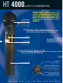
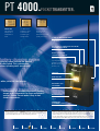
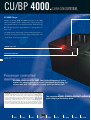
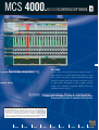
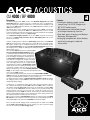
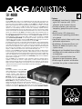
HT 4000
PT 4000
SR 4000
CU 4000
PS 4000
SRA 2B
PSU 4000
HPA 4000
MCS 4000
HPA/PSU
SOUNDS.BETTER.
4000.
WMS 4000.
BACKGROUND.
Professional wireless users have long sought
“tools of the trade” that provide a balance of uncompromised
audio with superior wireless performance. This challenge
motivated AKG’s engineers to create a system that offers both
complex technology and incredible functionality.
AutoSetup and EnvironmentScan
PC
Backlit Displays
2
THE WMS 4000 SYSTEM. The new WMS 4000 transforms
concert performances, corporate presentations and worship
Modular System
leadership into satisfying experiences. The combination of
quality engineering, exceptional flexibility, total versatility and
user friendly operation has evolved into an exceptional new
wireless system from AKG. Experience the creative power of
AKG.
T E C H N O L O G Y
HT 4000
PT 4000
SR 4000
CU 4000
PS 4000
T O
SRA 2B
M A K E
PSU 4000
HPA 4000
MCS 4000
True Diversity
Wideband UHF
High RF Output
Control
Plug-in Battery Charging System
SBMS
Smart Battery Management System
Battery Life – 15 hours
3
with 2 AA size batteries
Components
Interchangeable Microphone Elements
AKG’s Exclusive Acoustic Technology
Y O U R
Speech
Vocals
Reinforcement
W O R L D
Guitar/Bass
Instruments
Installed
Sound
B E T T E R
Live Sound
TV Studio
Theater
Houses
of Worship
HT 4000.
HANDHELDTRANSMITTER.
HANDHELD
TRANSMITTER.
Transform Yourself.
Capturing every nuance of vocal
expression, the WMS 4000 System amplifies the energy of your
performance and expands the interaction between artist and
audience. Thus, the system creates satisfaction from an
engineering perspective, as well the higher level of artistic
SIX INTERCHANGEABLE
MICROPHONE ELEMENTS
100% AKG Acoustics:
TEC Award winning C 900
Emotion Series D 880
Tri-Power D 3700, D 3800, C 5900,
C 535.
communication.
The pilot tone system transmits all important transmitter data
to the receiver for reliable, interference-free operation.
STATUS LED
Indicates the system’s
current operating status.
The revolutionary WMS 4000
CU 4000 charger and BP 400
battery charging simple and re
BACKLIT DISPLAY
Ensures easy setup and
accurate status monitoring
even on a dark stage.
4
The SBMS Smart Battery Management System ensures a battery life of 15 hours
or 12 hours with the BP 4000 battery pack.
JOG SWITCH
Easy-to-use, single control for setting
all function parameters.
SOFT TOUCH ENAMEL FINISH
Helps reduce handling noise.
CHARGING AND PROGRAMMING CONTACTS
Allows the optional BP 4000 battery pack
to be charged inside the transmitter and
new frequency Presets to be programmed by
the AKG Service Department.
ELECTRONICALLY LOCKABLE ON/OFF BUTTON
AND PROTRUDING MUTE SWITCH
Easily distinguishable, the two controls
provide simple, but important functionality.
HT 4000
PT 4000
SR 4000
CU 4000
PS 4000
SRA 2B
PSU 4000
HPA 4000
MCS 4000
PT 4000.
POCKETTRANSMITTER.
POCKET
TRANSMITTER.
REMAINING
BATTERY LIFE
The remaining
battery life is
illuminated in
hours.
GAIN MENU
The Gain menu
provides a choice
of manual and
automatic gain
setting modes.
DATA SHEET
MORE INFO
FREQUENCY PRESETS
Intermodulation-free
frequencies for
setting up a
multichannel system
quickly and easily.
.1" JACK FOR REMOTE MUTE SWITCH
Allows easy muting even if the bodypack transmitter
is concealed.
ELECTRONICALLY LOCKABLE ON/OFF BUTTON AND
PROTRUDING MUTE SWITCH
RUGGED, PROFESSIONAL
3-PIN MINI XLR CONNECTOR
Accepts all AKG microphones
with a mini XLR connector
including MicroMics, CK 77 WR
and Discreet Acoustics
Modular Series lavalier
modules, etc.
charging system includes the optional
00 battery pack. This system makes
educes operating costs considerably.
5
STATUS LED
BACKLIT DISPLAY
s with a pair of AA size batteries
ENSCRIBABLE COLOR
CODE ELEMENT
A wide choice of selectable frequencies provides
enough usable frequencies for large multichannel
systems. Factory Presets make it easy to find
suitable frequencies.
MAGNESIUM BODY
Light and extremely
rugged.
CHARGING AND
PROGRAMMING CONTACTS
H
E
L
P
F
U
L
H
I
N
T
S
WMS 4000 transmitters provide a “SILENT MODE” in which you can set all system parameters – such
as carrier frequency, gain, etc. – without transmitting an RF signal. This allows you to set up a
replacement transmitter behind the scene without disrupting a performance.
HT 4000
PT 4000
SR 4000
CU 4000
T
E
C
H
N
O
T
E
The HT 4000 and PT 4000 transmit a pilot tone (approx. 30 KHz) “hidden” inside the radio signal to
the receiver. This allows the pilot tone detection circuit of the receiver’s Tone Code Squelch (TCSQ) to
determine whether there is an active transmitter inside the coverage area and then activate or mute
the audio output without any noise. In addition, important transmitter status information such as
remaining battery life and the MUTE switch position can be shown on the receiver’s display.
PS 4000
SRA 2B
PSU 4000
HPA 4000
MCS 4000
SR 4000.
STATIONARYRECEIVER.
STATIONARY
RECEIVER.
True Diversity ensures maximum reliability of reception and a
30 MHz wide UHF channel provides enough room for many simultaneous
channels to operate together.
AUTO-SETUP
Finds usable frequency groups and sets
frequencies automatically.
ENVIRONMENT SCAN
Analyzes the UHF environment to ensure
interference-free transmission.
6
REHEARSAL
This function records transmission parameters used in practice in order to facilitate
system setup for actual performances.
REMAINING BATTERY LIFE DISPLAY
Indicates current battery capacity in hours.
Includes transmitter data processing and automatic TCSQ Tone Code Squelch circuits.
The pilot tone detector can be deactivated if necessary and the squelch threshold set m
H
E
L
P
F
U
L
H
I
N
T
S
ENVIRONMENT SCAN AND REHEARSAL FUNCTIONS. The SR 4000 provides a number of useful
functions that make setting up a professional system simple and considerably improve operational
dependability. Environment Scan examines the receiver’s local RF environment and warns of any
interfering frequencies such as active TV transmissions, etc. The Rehearsal Function is another early
warning system that records the most important transmission parameters and can be used during
the soundcheck to identify potential problems ahead of time.
HT 4000
PT 4000
SR 4000
CU 4000
T
E
C
H
N
O
T
E
MULTICHANNEL CAPABILITY, FREQUENCY MANAGEMENT, AUTO SETUP. Its wide frequency range and
1200 selectable frequencies make the WMS 4000 an excellent choice for multichannel systems. The
built-in frequency management system helps you find the most reliable frequencies. Each factory
preset provides a set of intermodulation-free frequencies. The Auto Setup function rapidly identifies
“clean” frequencies. For a FREE download of the AKG frequency management program for your PC,
visit www.akg.com/frequencies.
PS 4000
SRA 2B
PSU 4000
HPA 4000
MCS 4000
DATA SHEET
MORE INFO
BNC ANTENNA INPUTS
For connecting a pair of antennas or a complex antenna network.
LOCKING DC INPUT
For secure connection to a local or central power supply, e.g., PSU 4000.
LOGIC OUT
For remote control of functions on external devices such as
automatic microphone mixers or
media control systems.
DATA I/O
For remote control from a PC using MCS
4000 control software.
PROFESSIONAL XLR AND 1/4" AUDIO OUTPUTS
With output level selector.
ALL-METAL HALF-RACK CASE
Complete with rugged rack mounting kit.
BACKLIT DISPLAY
High-contrast “black mask” color display provides
a clear readout of all system parameters.
PROGRAMMABLE STATUS LED RING
Provides a clearly visible indication of battery, audio level, RF level,
or diversity status.
JOG WHEEL
For easy receiver setup.
Allow control and monitoring of multichannel systems from a PC.
manually.
CONFIDENCE.
T
E
C
H
N
O
T
longer at the mercy of conventional equipment and its in-
E
FIRMWARE REPROGRAMMING. The wireless world changes rapidly and so do frequency plans all over
the world. Therefore, many less flexible systems may not be used legally when their programmed
frequencies are reallocated. If the need arises, authorized AKG Service Centers will be glad to
reprogram all WMS 4000 components for new frequencies quickly to “legalize” your system again.
HT 4000
PT 4000
SR 4000
Dependability overcomes concern. You’re no
CU 4000
consistencies, but free to maximize your creativity. Interferencefree reception, accurate response and dependable technology
free your mind to focus on what you do best…perform.
PS 4000
SRA 2B
PSU 4000
HPA 4000
MCS 4000
7
CU/BP 4000.
CHARGINGSYSTEM.
CHARGING
SYSTEM.
CU 4000 Charger
Charger for two HT 4000 / PT 4000 transmitters or BP 4000
replacement battery packs. Battery packs charge quickly and
easily without having to be removed from the transmitter. The
Quick Charge System will charge batteries to capacity within one
hour or less.
The SBMS system permanently monitors battery parameters. If
necessary, a recovery function allows “aging” battery packs to be
“rejuvenated” to prolong their useful life.
CHARGING STATUS LED
8
RECOVER BUTTON AND LED
Starts a battery recovery cycle. The SBMS detects and indicates the
need for battery servicing, which will prolong the useful life of the
battery pack.
Maximum convenience: The SBMS Smart Battery Management System
monitors the charging process to prevent battery pack overcharging and
ensures more than 1000 complete charging cycles per battery pack.
H
E
L
P
F
U
L
H
I
N
T
S
BATTERY CARE. Rechargeable batteries are known to suffer from “memory effect”. The capacity of a
rechargeable battery will decrease over time if it is not fully discharged. If a battery is discharged
only to 50% of its capacity over many charging cycles, it finally “believes” its capacity is only
50% and cannot be fully charged any more. To eliminate memory effect, we recommend completely
discharging and recharging the battery pack periodically (recovery cycle). The SBMS permanently
monitors battery parameters and detects the need for a recovery cycle. The RECOVER LED lights to
indicate it is time for servicing the battery pack. Since a recovery cycle may take 14 hours, the best
time to run it is during the night. In any case, you will need to start the recovery cycle manually. If
you service your battery pack regularly it will retain its maximum capacity throughout its useful life.
HT 4000
PT 4000
SR 4000
CU 4000
Two-compartment power management allows simultaneous
quick-charging of two battery packs.
PS 4000
SRA 2B
PSU 4000
HPA 4000
MCS 4000
DATA SHEET
MORE INFO
TWO UNIVERSAL CHARGING COMPARTMENTS
Accepts HT 4000 and PT 4000 transmitters
or BP 4000 battery packs.
Several chargers can be
mounted in a rugged
LOCKING DC INPUT
For secure connection to a local or
central power supply, e.g., PSU 4000.
flightcase as a
compact, “roadworthy”
solution for large
systems.
BP 4000 intelligent, quick-replacement battery pack
INTERNAL RAM
Stores charge/discharge
process data and provides
a database for optimizing
charging parameters
(Charge Balance
Management).
9
DATA INTERFACE
Sends battery status information to the
transmitter electronics for accurate
capacity readout.
INTEGRATED TEMPERATURE SENSOR
Protects the battery pack from
overcharging and damage.
T
s, easy to use
REMAINING BATTERY
LIFE READOUT
Displays the current
battery capacity in
hours.
HT 4000
PT 4000
SR 4000
CU 4000
E
C
H
N
O
T
E
SMART BATTERY MANAGEMENT SYSTEM. An environmentally friendly money saver, the SBMS Smart
Battery Management System is the heart of a completely new charging technology. It monitors battery
status and controls the charging process. The battery status visibly seen in remaining hours of
battery life on the transmitter and receiver displays, so you can recharge the battery pack before it
loses power. The SBMS includes a number of intelligent monitoring functions. Inflection Point and
Peak Voltage Detect stops the charging in time, while an integrated temperature sensor in the battery
pack protects the battery pack from overheating. The Charge Balance Management feature makes
sure that only as much energy will be fed to the battery pack as had previously been drawn from it.
A self-discharge counter ensures correct charging after the battery pack has been stored for a long
time. The battery pack uses an integrated database and charger interface to set its own charging
current.
PS 4000
SRA 2B
PSU 4000
HPA 4000
MCS 4000
PS 4000.
ANTENNASYSTEM.
ANTENNA
SYSTEM.
THE SPIRIT OF EXCELLENCE.
The WMS 4000 tells a story
of team spirit and excellence in engineering. The knowledge and
creative resources of AKG designers, supported by painstaking
attention to every detail, made this excellent system possible. We
are witnessing a new era of wireless technology that offers an
entirely new meaning to the word “professional”. It brings per-
Wideband antenna splitter for four SR 4000
receivers. Expandable for up to 50 or more
receivers. Optimum performance at a
reasonable cost.
fection in its purest form to the world of professional audio.
2 BNC ANTENNA INPUTS
For connecting active or passive antenna
system components.
LOCKING DC INPUT
For secure connection to a local or central power supply,
e.g., PSU 4000.
2 EXPANSION OUTPUTS
For connecting another antenna splitter.
10
STATUS DISPLAY
Lets you check the
current operating condition of
the entire antenna network at
a glance.
8 BNC ANTENNA OUTPUTS
For connecting one to four diversity
receivers together.
SWITCH BANK FOR MATCHING THE UNIT TO THE CONNECTED CABLE LENGTH
Set of calibration switches for optimizing RF input signal quality.
The antenna inputs and outputs carry a power bus for remote powering of connected antenna
system components. This keeps wiring simple and ensures quick and easy system installation.
H
E
L
P
F
U
L
H
I
N
T
S
SELECTING AND PLACING RECEIVING ANTENNAS. The receiving antenna is the “ear” of a radio
system. To get the best possible signal quality, select and place your antennas carefully. Antennas
have polar patterns like microphones, so depending on the application at hand you may need Yagi
(cardioid/hypercardioid), log periodic (shotgun), or omnidirectional antennas. If the transmitters will
be used within a rather small area such as a stage, use directional antennas. Directional antennas
are generally used to overcome long distances or suppress off-axis interference, e.g., in open-air
concert situations. Omnidirectional antennas are ideal for near-field applications where no off-axis
interference is expected, e.g., indoor events (most directional antennas are big and difficult to
conceal) or multipurpose halls with no preferred direction.
SRA 1 passive, wideband directional antenna
• For indoor or outdoor use, specifically, for setting up
long-range radio links (up to 100 m/330 feet)
• For use with antenna cables up to 5 m (16 feet) long
• Water-resistant case, BNC output
HT 4000
PT 4000
SR 4000
CU 4000
PS 4000
SRA 2B
PSU 4000
HPA 4000
MCS 4000
DATA SHEET
MORE INFO
SRA 2B active, wideband directional antenna
ASU 4000 Remote power supply
• For indoor or outdoor use, specifically, for setting up radio
Remote power supply for complex antenna networks
links for distances up to 300 m
• BNC or N input and output
(approx. 1000 ft.)
• Locking DC input
• Status LED
• Integrated high-performance
• Water-resistant case
antenna booster for use
with antenna cables up to
200 m (approx. 655 ft.)
CABLES
long
RG 58 antenna cables are available in various lengths for
• Remote powering option
applications from small clubs to large stadiums. Antenna cables
• Water-resistant case, BNC output
of other types are available upon request.
• Status LED
• Optional laser positioning pointer
RA 4000 B omnidirectional wideband booster
antenna
TV studio
Theater
House of Worship
11
• For indoor or outdoor use, specifically, for near-field antenna
setups with no preferred direction
• Integrated high-performance antenna booster for use with
Installed sound
antenna cables up to 180 m (approx. 600 ft.) long
• Remote powering option
Live sound
Flexible, modular, cost effective accessories are
available for setting up antenna networks of any level
of complexity. WMS 4000 accessories provide
optimum wireless solutions for applications from
small houses of worship to huge stadiums.
• Rugged, water-resistant case, BNC output
• Status LED
AB 4000 antenna booster
High-performance antenna booster for inserting into long antenna
cables. One AB 4000 can compensate for approximately 17 dB
of cable attenuation, allowing RG 213 cable runs to be extended
by approx. 60 m (200 feet). Up to three AB 4000 boosters can
be used in series for extremely long cable runs.
• BNC or N input and output
• DC input
• Status LED
• Water-resistant case
HT 4000
PT 4000
SR 4000
CU 4000
T
E
C
H
N
O
T
E
SELECTING CABLES/CABLE ATTENUATION/COMPENSATION. Antenna cables feed the output signal of
a remote antenna to the receiver. Any cable, however, will attenuate the antenna signal. Since
different types of cables have different attenuation values, each type will perform best at a different
length. Although low-attenuation cables are usually thicker and more expensive than lower-grade
cables, they can be used for much longer runs. You can compensate for high cable attenuation by
using antenna boosters or active antennas. In some cases, however, using the next higher (if slightly
more expensive) grade of cable may do the trick, eliminating the need to use active antenna
components. The right type of cable can be essential to the performance of your wireless system,
prevent problems, and help reduce costs. For more information contact AKG Acoustics, your local AKG
supplier or visit www.akg.com.
PS 4000
SRA 2B
PSU 4000
HPA 4000
MCS 4000
HUB 4000.
NETWORKCONCENTRATOR.
NETWORK
CONCENTRATOR.
HUB 4000
PC network interface for connecting up to eight SR 4000
DATA I/O
For reliable communication with a PC and
the MCS 4000 Mission Control Software.
receivers to an Ethernet network. The HUB 4000 can be
expanded as desired using standard PC components such as
Ethernet hubs or wireless LAN interfaces.
8 NETWORK CONNECTORS
For up to eight diversity receivers.
ON/OFF SWITCH
STATUS LED
LOCKING DC INPUT
For secure connection to a local or
central power supply, e.g., PSU 4000.
ACTIVE CHANNEL
DISPLAY
12
A sing
Clear, easy-to-read graphic representation of the local RF environment for optimal fr
PURE PERFECTION. Our customers’ stringent requirements provided
the original inspiration for our engineers. Their dreams
materialized into a line of precisely matched components that
make the WMS 4000 Series an indispensable tool for professional
wireless applications. Driven by a broader vision of audio technology, the innovative spirit of AKG has created a system of unique
adaptability for any live sound situation. It is an excellent choice
for every venue and every kind of event. Its integrated intelligence
enables the system to be expanded easily as the evolution of audio
technology progresses. The WMS 4000 is designed and built to
stand the test of time.
HT 4000
PT 4000
SR 4000
CU 4000
H
E
L
P
F
U
L
H
I
N
T
S
PC SUPPORTED ONSTAGE SETUP. You can make your wireless multichannel system even easier to use
and even more reliable by connecting the WMS 4000 network components to standard computer
peripherals. This allows you to send receiver data through the HUB 4000 to a wireless LAN and
receive them on a tablet PC. You can take the computer on the stage and monitor important
parameters such as RF levels right where the action is. This speeds up system setup and increases
the reliability of the wireless system.
PS 4000
SRA 2B
PSU 4000
HPA 4000
HUB 4000
MCS 4000.
MISSIONCONTROLSOFTWARE.
DATA SHEET
MORE INFO
13
MCS 4000
gle screen shows all important parameters.
Remote control and remote monitoring software. Displays all
status indicators of a complete multichannel system on a single
screen. Special indicators including minimum/peak bar graph
meters show current signal levels and give an indication of over-
equency setting.
all signal quality. The program includes a graphic spectrum
analyzer and a frequency management database that can be
updated through the Internet.
Program your multichannel system in a series of easy steps.
Frequency Presets can be updated via the Internet.
T
E
C
H
N
O
T
E
“GET-A-CUP” SETUP. Finding and setting the right frequencies for a multichannel system is a
difficult and time-consuming job. The WMS 4000 provides several functions including AutoSetup and
EnvironmentScan to speed up the process. The MCS 4000 from AKG is an incredibly convenient
software tool. It scans the system’s UHF band and uses an integrated frequency management
database to calculate optimum frequencies. It automatically programs the frequencies into the
receivers via the HUB 4000 to complete the setup while you wait just a few minutes.
HT 4000
PT 4000
SR 4000
CU 4000
PS 4000
SRA 2B
PSU 4000
HPA 4000
MCS 4000
HPA/PSU 4000.
HPA 4000 headphone amplifier
LOCKING DC INPUT
For secure connection to a local or central power supply,
e.g., PSU 4000.
Headphone amplifier with eight inputs for SR 4000 receivers
and one headphone output.
EIGHT 1/4" LINE LEVEL AUDIO INPUTS
ON/OFF SWITCH
HEADPHONE JACK
DISPLAY indicates the
current active channel.
JOG WHEEL
Selects the signal you wish to monitor
and sets the volume.
PSU 4000 central power supply
Powers up to 12 SR 4000 receivers plus antennas via three
PS 4000 antenna splitters to keep wiring simple. Also powers
3 DC OUTPUTS
the CU 4000, HPA 4000, and HUB 4000.
100 VAC - 230 VAC INPUT
14
ON/OFF SWITCH
STATUS DISPLAY
Microphones for the HT 4000
D 880 WL 1 D 3700 WL 1
D 3800 WL 1
C 900 WL 1
C 5900 WL 1
C 535 WL 1
GN 15 HT
Microphones for the PT 4000
LM 3 L
C 411 L
HT 4000
C 416 L
PT 4000
C 417 L
C 419 L
SR 4000
D 409 L
CU 4000
C 420 L
PS 4000
C 444 L
SRA 2B
C 477 WR L
CK 55 L
CK 77 WR L
PSU 4000
HPA 4000
MCS 4000
APPLICATIONS.
1. MULTICHANNEL SYSTEM WITH MEDIUM-LENGTH CABLES
19” Rack / Front view
19” Rack / Rear view
Internal antenna cables (MK PS)
External antenna cables
AC power/12 V DC cables
Fig. 1
19” Rack / Front view
Refer to fig. 1 for antenna distribution diagram.
2. MULTICHANNEL SYSTEM WITH LONG CABLES
19” Rack / Rear view
15
2 AB 4000s
max.
2 AB 4000s
max.
Internal antenna cables (MK PS)
External antenna cables
Antenna splitter expansion cables (MK PS)
12 V DC cables
AC power cables
3. MULTICHANNEL SYSTEM WITH DIFFERENT-LENGTH CABLES
Internal antenna cables (MK PS)
External antenna cables
Antenna splitter expansion cables (MK PS)
AC power/12 V DC cables
Data cables
Audio cables to HPA 4000 headphone amplifier
19” Rack / Rear view
Refer to fig. 1 for antenna distribution diagram.
19” Rack / Front view
2 AB 4000s
max.
2 AB 4000s
max.
schaefer-design.at
HT 4000
Carrier frequency range
Modulation
Audio bandwidth
THD
Signal/noise ratio
RF radiation
Battery life
Dimensions
Net weight
Standard accessories
650 to 680, 680 to 710, 720 to 750,
760 to 790, 790 to 820 and 835 to 863 MHz
FM
35 to 20,000 Hz
<0.3% typical
120 dB(A)
50 mW max. (ERP)
2 AA size alkaline batteries:
15 hours; BP 4000: 12 hours
length: 239 mm (9.4 in.); diameter: 39 mm (1.5 in.)
320 g (11.3 oz.)
SA 63 stand adapter, 2 AA size dry batteries, Color Coding Kit
PT 4000
Carrier frequency range
Modulation
Audio bandwidth
THD
Signal/noise ratio
RF radiation
Battery life
Dimensions
Net weight
Standard accessories
650 to 680, 680 to 710, 720 to 750,
760 to 790, 790 to 820 and 835 to 863 MHz
FM
35 to 20,000 Hz
<0.3% typical
120 dB(A)
50 mW max. (ERP)
2 AA size alkaline batteries: 15 hours typical;
BP 4000 rechargeable battery pack: 12 hours typical
70 x 90 x 25 mm (2.8 x 3.5 x 1 in.)
320 g (11.3 oz.)
belt clip, 2 AA size dry batteries, Color Coding Kit
SR 4000
RF carrier frequency range
Modulation
Audio bandwidth
THD
Signal/noise ratio
Audio outputs
Dimensions
Weight
Standard accessories
Optional accessories
650 to 680, 680 to 710, 720 to 750,
760 to 790, 790 to 820 and 835 to 863 MHz
FM
35 to 20,000 Hz
>0.3% typical
120 dB(A)
balanced 3-pin XLR; unbalanced TS 1/4" jack;
output level adjustable to -30, 0, +6 dB
200 x 44 x 190 mm (7.8 x 1.7 x 7.4 in.)
972 g (2.2 lbs.)
Power supply, Color Coding Kit, 2 UHF antennas,
RMU 4000 rack mounting kit
MK 9/10 microphone cable
AKG Acoustics GmbH
Lemböckgasse 21–25, P.O.B. 158, A-1230 Vienna/AUSTRIA,
Tel: (+43 1) 86 654-0*, Fax: (+43 1) 86 654-7516, www.akg.com, e-mail: [email protected]
Hotline: (+43 676) 83200 888, [email protected]
For detailed information on WMS 4000 Series and other AKG
products contact your distributor or visit our website:
www.akg.com
Specifications subject to change without notice.
AKG Acoustics GmbH
Bodenseestraße 228, D-81243 München/GERMANY, Tel: (+49 89) 87 16-0,
Fax: (+49 89) 87 16-200, www.akg.com/de, e-mail: [email protected]
Hotline: (+49 89) 87 16-22 50, [email protected]
02/04/PROA 1503
AKG Acoustics, U.S.
914 Airpark Center Drive, Nashville, TN 37217, U.S.A., Tel: (+1 615) 620-3800,
Fax: (+1 615) 620-3875, www.akgusa.com, e-mail: [email protected]
world wide wireless with AKG
www.akg.com
HT 4000
PT 4000
SR 4000
CU 4000
PS 4000
SRA 2B
PSU 4000
HPA 4000
MCS 4000
HT 4000 / PT 4000
Description
The AKG PT 4000 bodypack and HT 4000 handheld transmitters have identical
transmission characteristics, with a maximum radiated output power of 50 milliwatts.
Through special signal companding circuits (compression and expansion), dynamic
range capability greater than 120 dB is delivered at the receiver’s output. Audio
bandwidth of the system is uniform from 35 Hz to 20 kHz. The
usable distances between the receiver and transmitter can be
100 meters (330 ft) or more. Individual handheld microphone
and bodypack transmitters are factory-matched to each
receiver. Each system operates on a 30 MHz-wide UHF channel
and includes a set of Presets containing Intermodulation Free
frequencies as well as a search tuning mode with access to
up to 1,200 switchable frequencies. In the U. S., a total of
three bands of 30 MHz channels may be selected. The user
may expect a maximum of approximately 50 usable channels
in a given locale (depending on the local TV channels and wireless
frequencies used). In addition to the modulated audio signal, the
transmitters send out a data-encrypted PilotTone (at 32,768 Hz)
to send important information such as battery status, mute status
and more to the system´s receiver.
The HT 4000 handheld and PT 4000 bodypack transmitters can
be powered by 2 AA batteries and normal battery life of up to 15
hours can be expected from standard 1.5-volt alkaline cells. An
optional BP 4000 rechargeable battery pack is available, featuring
Smart Battery Management System Software, and can provide
battery life of up to 12 hours plus the remaining battery life can
be monitored on the transmitter's & receiver's displays.
Both transmitters come with a backlit display and a jog element
for easy setup and full status control. The display features
information on selected frequency, gain setting, and remaining
battery life in hrs. as well as LOCK and MUTE status. Beside the
display and the jog element, the controls on the HT 4000 &
PT4000 include lockable ON/OFF button and a separate MUTE
switch whose position is easily distinguishable as well as a status
indication LED. An inscribable color code facility helps easy
channel recognition in multi-channel systems.
The PT 4000 bodypack accepts both microphone and line-level
input signals, and the input sensitivity can be adjusted from 0 –
25 dB for optimum gain matching. The antenna is a quarterwavelength type that affords easy concealment and comfortable
wearing. A lockable TA-3F Mini-XLR connector is available for easy
connection of a broad range of AKG headset, lavalier or instrument
mics (e.g. MicroMic Series microphones) as well as instrument
cables. The PT 4000 also comes with a 2.5-mm jack connector
suitable for the optional RemoteMuteSwitch device RMS 4000.
The HT 4000 handheld transmitter comes with a rugged mechanical
solution for interchangeable microphone modules. Six of AKG’s most popular
handheld "vocal" microphone head units are available for the handheld
transmitter model. The microphones are the dynamic models D 880
WL1, D 3700WL 1, D 3800 WL 1 as well as the condenser models
C 900 WL1, C 5900 WL 1, and C 535 WL 1.
Battery Status
Auto Gain
Preset Frequencies
Features
• Wideband UHF handheld transmitters
with interchangeable acoustics
Wideband UHF pocket transmitters
with die-cast metal housings
• Pre-matched, optimized frequency
groups for quick, easy frequency
selection (Presets)
• Backlit LCD Displays for easy status
monitoring
• Simple, fool-proof setup procedure
using Jog element for quick navigation
• Integrated charging contacts for
convenient recharging of optional
battery pack
• Continuous operation of >15 hrs. with
2 x AA alkaline batteries or > 12 hrs.
with optional BP 4000 rechargeable
battery pack
• Up to 24 intermodulation-free preset
groups available on each frequency
band
• Wide range of optional accessories
available for system customization
Line Drawings
Audio Bandwidth: 35 –20,000 Hz
Carrier Frequency Range: 650 – 680, 680 – 710, 720 – 750, 760 – 790,
790 – 820, 835 – 863 MHz
Carrier Frequencies: up to 1,200
Modulation Method: FM
Rated Deviation: ±20 kHz nominal
S/N Ratio (A-weighted): > 120 dB(A)
Radiated RF Power: 50 mW ERP
Audio Input: Mini XLR, 3 pin
Current Consumption: < 135 mA
Power Requirement: 2 AA 1.5-V batteries or BP 4000 rechargeable pack
Typical Battery Life: Alkaline batteries, 15 hours; BP 4000: 12 hrs.
Size: 2.8 x 3.5 x 1 in. (70 x 90 x 25 mm)
Net Weight: 11.3 oz. (320g) without batteries
(us standard and metric measures)
HT 4000 Handheld
2.8 inch (70 mm)
9.4 inch (239 mm)
ø 1.5 inch (39 mm)
Audio Bandwidth: 35 –20,000 Hz
Carrier Frequency Range: 650 – 680, 680 – 710, 720 – 750, 760 – 790,
790 – 820, 835 – 863 MHz
Carrier Frequencies: up to 1,200
Modulation Method: FM
Rated Deviation: ±20 kHz nominal
S/N Ratio (A-weighted): > 120 dBA
Radiated RF Power: 50 mW ERP
Input Level: 140 dB-SPL @ nominal deviation
Current Consumption: <125 mA
Power Requirement: 2AA 1.5-V batteries or rechargeable pack BP 4000
Battery Life: Dry batteries, 15 hours, BP 4000: 12 hrs.
Size: lenght: 9.4 in. (239 mm); diameter: 1.5 in. (39 mm)
Net Weight: 11.3 oz. (320g) without batteries
1 inch
(25 mm)
PT 4000 Bodypack
3.5 inch (90 mm)
Specifications
Architects and Engineers Specifications
The wireless system shall operate over a 30 MHz UHF frequency range
in one of 6 bands from 680 to 863 MHz, with a wide range of possible
frequency settings. The wireless microphone system shall incorporate
factory-optimized sets of both transmission and receiving frequency
modules that are programmed into both transmitters and receivers. Each
frequency set shall comprise a 30 MHz UHF band and offer up to 1,200
discrete operating frequencies within that band, with transmitter power
not exceeding 50 milliwatts. Both handheld and bodypack type transmitters shall be provided. The bodypack transmitter shall accommodate
both microphone and line level inputs. The transmitters shall operate
with a companding system that is complemented by the receiver,
providing an A-weighted system dynamic range in excess of 120 dB.
The transmitters shall indicate input overload via an LED indicator and
on a backlit display battery lifetime shall be displayed in hours as well
as the transmitting frequency. Handheld transmitters shall have a
maximum diameter of 39 mm and a length, including antenna, no greater
that 239 mm. The wireless microphone system shall be the AKG
Acoustics Model WMS 4000.
AKG Acoustics GmbH
Lemböckgasse 21–25, P.O.B. 158, A-1230 Vienna/AUSTRIA,
Tel.: (+43 1) 86 654-0*, Fax: (+43 1) 86 654-7516, www.akg.com, e-mail: [email protected]
Hotline: (+43 676) 83200 888, [email protected]
AKG Acoustics, U.S.
914 Airpark Center Drive, Nashville, TN 37217, U.S.A.,
Tel.: +1-615-620-3800, Fax: +1-615-520-3875,
www.akgusa.com, e-mail: [email protected]
For detailed information on WMS 4000 and other products from AKG contact your dealer
or visit www.akg.com
Specifications subject to change without notice.
02/04/Proa-Nr. 1453
www.akg.com
CU 4000 / BP 4000
Description
The AKG charging system 4000 consists of the CU 4000 charging unit and the BP
4000 battery pack. The charging unit itself is a stand-alone unit in a rugged plastic
housing, featuring 2 charging compartments, each mechanically designed to hold
either one HT 4000 handheld transmitter, a PT 4000 bodypack transmitter or a BP
4000 spare battery pack.
Two battery packs can be charged simultaneously by the CU 4000, if the battery
pack is installed in either the HT 4000 or PT 4000 transmitters. There is no need
to remove the battery pack from the transmitters since these transmitters are equipped
with on- board charging contacts for a plug-in charge.
The sophisticated charging electronics of the CU 4000 comprises revolutionary
functions to carefully charge and service the BP 4000 battery packs over the full
lifetime of the battery.
The basic charging function is based on a trickle charge system with so-called inflection
point switch-off automation. Safety switch off occurs by detection of the peak voltage,
the negative voltage slope or a predetermined time out. Thus the battery pack is
prevented from overcharging. An integrated two-slot power management system allows
the Charging unit to charge two battery packs simultaneously in
approximately 1 hour.
Since the BP 4000 battery pack incorporates microprocessor-controlled surveillance intelligence, there
is a permanent data stream between the Charging
Unit and the Battery Pack to protect the batteries
from any damage caused by the charging process.
A charge balance management circuit controls the
exact amount of energy to be charged in the pack
as the amount that was taken out of the pack (2nd
level overcharge protection). The charge balance
management also features a self-discharging counter
used to detect the exact battery pack status after a
long period of storage. With the help of this charge
balance management, an accurate remaining battery life
display can be realized on the transmitters (transferred via pilot
tone to the SR 4000 receiver).
All necessary battery pack data will be stored in the internal RAM or EPROMmemory of the pack. All predetermined and initial parameters are stored in EPROMmemory of the battery pack to perform a correct recovery cycle.
The battery pack also features an internal temperature surveillance circuit that adjusts
the charging current of the CU4000 to protect the device in case of low or high
temperature during loading.
To reduce the so-called memory effect which leads to decreasing battery capacity,
the communication between the BP 4000 and the CU 4000 is able to calculate if
the batteries need a recovery cycle by the help of the stored date in the BP 4000.
In this case, the CU 4000 draws the user’s attention to this possible problem and
suggests starting a recovery cycle. The user can activate the recovery cycle via a
recovery button on the CU 4000´s front panel. The recovery cycle refreshes the battery
pack by charging and discharging cycles to determine the actual capacity and initialize
the capacity counter for accurate use time calculation.
Other controls include a 3-step LED display showing the charging status. A lockable
DC connector on the rear panel of the CU allows the unit to be powered by either an
external DC adapter or by the optional PSU 4000 central power supply.
Due to the sophisticated charging system, the battery pack can power the HT 4000
and PT 4000 for up to 12 hours with one full charging cycle, plus its gentle charging
function will ensure up to 1,000 charging cycles.
Features
• Intelligent battery supply system
comprising CU 4000 charger and
BP 4000 battery pack
• Microprocessor controlled charge/
discharge monitoring function
• One-hour quick charging and Battery
Recovery Management
• Charging compartment allows battery
pack to be charged inside the
transmitter
Specifications
CU 4000
Line Drawings
Charging current: 1.5 A
Operating voltage: 12 VDC, 1.3 A
Charging time: 1 hour typical
Recovery cycle: approx. 8 hours
Dimensions: 3.6 x 6.8 x 3.3 in. (92 x 173 x 85 mm)
Weight: approx. 20.5 oz. (580 g)
Standard accessories: BP 4000 battery pack, power supply
(us standard and metric measures)
3.6 inch (92 mm)
3.3 inch (85 mm)
Several chargers can be mounted
in a rugged flightcase as a
compact, “roadproof“ solution
for large systems.
AKG Acoustics GmbH
Lemböckgasse 21–25, P.O.B. 158, A-1230 Vienna/AUSTRIA,
Tel.: (+43 1) 86 654-0*, Fax: (+43 1) 86 654-7516, www.akg.com, e-mail: [email protected]
Hotline: (+43 676) 83200 888, [email protected]
AKG Acoustics, U.S.
914 Airpark Center Drive, Nashville, TN 37217, U.S.A.,
Tel.: +1-615-620-3800, Fax: +1-615-520-3875,
www.akgusa.com, e-mail: [email protected]
For detailed information on WMS 4000 and other products from AKG contact your dealer
or visit www.akg.com
Specifications subject to change without notice.
02/04/Proa-Nr. 1453
www.akg.com
1,2 inch
(30,2 mm)
0,7 inch
(18 mm)
6.8 inch (173 mm)
2,2 inch (57,5 mm)
SR 4000
Description
a) Hardware
The SR 4000 UHF receiver is one standard EIA rack unit high and one-half rack unit
wide with a full metal chassis. Thus, two receivers can be placed side-by-side in one
rack space (rack-mount hardware included). The SR 4000 has a 30 MHz wide UHF
band containing presets with intermodulation-free frequencies as well as a tuning
mode with access to up to 1,200 switchable frequencies. The SR 4000 utilizes
operates as a true diversity receiver, in which two completely separate antenna,
receiver and demodulator sections are operational at all times. The receiver includes
a Pilot Tone Decoder Unit that decodes transmitter data out of the Pilot Tone's data
stream. This enables the SR 4000 to show battery charge status and mute status of
the transmitter on the integrated, back-lit color display. This data is also available at
the Logic Output Connector on the rear panel. The HT4000 & PT4000´s Pilot Tone
allows automatic muting of the SR´s audio output in case of invalid or corrupted
signal (Tone Code Squelch TCSQ). If necessary this automatic squelch option can be
overruled by a manual squelch setting. For PC control and monitoring of the SR unit
a special data port is available on the rear panel of the SR 4000.
The True Diversity receiver concept offers maximum dynamic range, greater freedom
from interference and noiseless switching from one receiver to the other. Both balanced
3-pin XLR and unbalanced 1/4-inch output connectors are available. An output level
switch allows the adjustment of 3 output levels (-30, 0, +6 dB) for optimum system
gain structure. Also available on the rear panel are a data port connector, a logic
output, 2 x BNC antenna Connectors and a lockable DC input jack.
Controls on the SR 4000 include a backlit display and a Jog wheel to adjust various
receiver settings such as squelch threshold, carrier frequency selection, user's name,
scan & rehearsal mode selection and many more. Indicators on the unit include mute,
audio level bargraph, RF level bargraph, 6x14 segment alphanumeric display and
menu control. A unique, programmable Status Control Ring shows the most important
system data at one glance.
Each SR 4000 can accommodate a pair of diversity antennas; however, when a
number of receivers are used in a single system, a master antenna pair (with or
without antenna booster, directional and omnidirectional antennas) can be used to
feed all receivers. A wide range of accessories such as an antenna splitter, antenna
combiner and antenna booster are provided for operational flexibility
and ease of installation.
b) Software
The internal software of the SR 4000
offers a wide range of control features for
an easy setup even in complex multichannel systems under difficult rf
conditions. Most helpful are features like
AutoSetup (automatic intermodulation
free channel selection), EnvironmentScan
(scanning of the unit's RF range), and
RehearsalMode (recording of important system data
during rehearsal helps optimize the system setup). Important
settings like frequency, squelch, unit name, etc. can be edited and
stored via an easy menu structure. Even more control & monitoring features are
available via the optional MCS 4000 (MissionControl Software) PC Control Software.
AutoSetup
RehearsalMode
EnvironmentScan
Battery Status / TX Mute
Features
• Wideband true-diversity frequencyagile UHF receiver with 1,200
channels and all-metal chassis
• Factory-selected, pre-matched
frequency groups for quick system
setup
• Backlit color LCD allows easy
monitoring of operating parameters
at a glance
• Jog wheel control allows quick, easy
parameter adjustments
• AutoSetup, EnvironmentScan and
Rehearsal Modes for quick, easy
system setup
• Bodypack and handheld transmitters
available with a wide selection of AKG
microphones
• Up to 24 intermodulation-free
frequencies per frequency group
• Wide range of optional accessories
available for system customization
Specifications
SR 4000 Receiver
Line Drawings
RF Carrier Frequency Ranges: 650 – 680, 680 – 710, 720 – 750, 760 –
790, 790 – 820, 835 - 863 MHz
Carrier Frequencies: up to 1,200 per range (dependent on local conditions)
Modulation Method: FM
Rated Deviation: 20 kHz at 1 kHz (sine wave)
Squelch Threshold: Adjustable between -70 and -100 dBm
Audio Bandwidth: 35–20,000 Hz
THD at 1 kHz: < 0.3% at rated deviation
Signal-to-noise: typ. 120 dBA
Audio Output: Balanced 3-pin XLR-M, switchable from -30 to +6 dB;
unbalanced 6.5 mm (1/4-in.) jack
Current Consumption: 150 mA typical
Power Requirement: 11 to 15 V dc or ac from external power supply
Size: 7.8 x 7.4 x 1.7 in. (200 x 190 x 44 mm)
Net Weight: 34 oz. (972 g)
(us standard and metric measures)
0.7 inch
(18 mm)
AKG Acoustics GmbH
Lemböckgasse 21–25, P.O.B. 158, A-1230 Vienna/AUSTRIA,
Tel.: (+43 1) 86 654-0*, Fax: (+43 1) 86 654-7516, www.akg.com, e-mail: [email protected]
Hotline: (+43 676) 83200 888, [email protected]
AKG Acoustics, U.S.
914 Airpark Center Drive, Nashville, TN 37217, U.S.A.,
Tel.: +1-615-620-3800, Fax: +1-615-520-3875,
www.akgusa.com, e-mail: [email protected]
For detailed information on WMS 4000 and other products from AKG contact your dealer
or visit www.akg.com
Specifications subject to change without notice.
02/04/Proa-Nr. 1453
www.akg.com
7.8 inch (200 mm)
1.7 inch (44 mm)
The wireless receiver shall operate over a 30 MHz UHF frequency range
in one of 6 bands from 680 MHz to 863 MHz, with a wide range of
possible frequency settings. The wireless microphone system shall
incorporate factory-optimized sets of both sending and receiving
frequency modules that are built into both transmitters and receivers.
Each frequency set shall comprise a 30 MHz UHF band and offer up to
1,200 discrete operating frequencies within that band. The receiver shall
operate on the true diversity principle, and the switching circuit shall be
inaudible. Total harmonic distortion at 1 kHz for rated deviation shall
be no greater than 0.3%. The receiver shall provide for a manual squelch
adjustment as well as an automatic squelch option (tone code squelch)
for optimum system operation. Audio output shall include a balanced
XLR connector as well as an unbalanced 6.3 mm / 1/4-inch jack
connectors. The output from the 3-pin XLR-type connector shall be
adjustable in 3 steps (-30, 0, +6 dB). A data port for connecting a pccontrolled network and logic out connector shall be provided. The receiver
shall be controlled by a jog wheel and shall provide a backlit color display
as well as a programmable LED ring (red/green) showing the overall
system status.
The wireless receiver shall be the AKG Acoustics Model SR 4000.
7.4 inch (190 mm)
Architects and Engineers Specifications
WMS 4000
Antenna System Components
Description
The AKG Model WMS 4000 is an extremely flexible and sophisticated wireless
microphone system for multi-user, multi-channel applications. A wide range
of accessories is available to customize the system to meet your specific needs
and deliver tremendous operational flexibility and ease of installation. In the
following, all the available components for setup of a sophisticated antenna
distribution scheme for multi-channel systems are described:
a) PS 4000 Multi-Coupler
The PS 4000 multi-coupler combines an antenna splitter and dc power distribution in a chassis that is one EIA standard rack unit high and one-half rack
unit wide in a full metal housing. Thus, two multi-coupler units can be placed
side by side (Rack Mount hardware kit included) or one PS 4000 side-by-side
with e.g. an SR 4000 receiver unit.
The PS 4000 has a wide-band antenna signal amplifier/divider with a 220 MHzwide UHF bandwidth, making it suitable for all available WMS 4000 channels.
The multi-coupler provides 2 BNC antenna inputs. The incoming diversity
signal is internally amplified and divided to 4 pairs of diversity
outputs, thus the splitter provides 2 x 4 BNC antenna
output connectors. 2 additional BNC outputs are
available on the rear panel for cascading the
diversity antenna signal to another
multi-coupler. Up to 3 multicouplers can be cascaded
to supply antenna signal
to 12 receivers from a
single pair of antennas.
The PS 4000 offers the
following displays: one
blue LED indicator for
each antenna input
showing that the connected cables, signal
amplifier and antennas are
fully operational. A red LED indicator
will indicate a failure of one of the components prior to the PS 4000.
A 10-position switch for compensation of the connected cable length is available
on the front panel to optimize the system’s performance. On the rear panel of
the PS 4000, a DC input can be hooked to either a single DC adapter or to the
optional central power supply unit, which can be connected to power the antenna
splitter and the connected receivers and antennas remotely via the antenna
cables.
Features
• High quality RF components to build
up extremely flexible and sophisticated
antenna networks with large antenna
cable lengths...
• ... and to build up distributed antenna
networks for room sharing applications
• Cascadeable, modular Antenna
splitter PS 4000
• Ultra linear Antenna Booster AB 4000
in waterproof housing
• High efficient passive and active
directional antennas SRA 1 & SRA 2B
• Discreet omnidirectional booster
antenna RA 4000 B for in & outdoor
use
• Wide range of useful accessories
b) AB 4000 Antenna Amplifier
The AB 4000 is an in-line antenna signal amplifier used to compensate
for the signal loss from cable attenuation in large antenna networks. The
amplifier comes with an ultra -linear rf amplifier circuit that offers up to
17 dB of amplification and can be remotely powered by the PS 4000 or
by an external AC adapter. Therefore it can be used with up to 90 m
(297 ft) of RG58 cable or 220 m (726 ft) of RG213 cable. In total, 2
AB 4000s can be cascaded in series without increasing the noise of the
wireless microphone system. To optimize the system’s performance, the
AB 4000 comes with a 10-position switch for compensation of the connected cable length. The antenna booster also is equipped with 2 BNC
connectors and 1 power indicator LED. The splitter comes in a waterproof
metal housing and therefore is even suitable for use outdoors.
c) RA 4000 B Amplified Antenna
The RA 4000B is an active omnidirectional antenna. Specially designed for
the WMS 4000 wireless microphone system, it comes with a specially-tuned
wideband UHF amplifier, perfectly matched to all WMS 4000 channels. The
integrated ultra linear rf amplifier circuit can be remotely powered by the PS
4000 antenna splitter and offers approximately 17 dB of amplification to
compensate for the cable attenuation of up to 40 m (132 ft) of RG58 cable
or 100 m (330 ft) of RG213 cable. If necessary, the SRA 2 can also be
cascaded with the optional AB 4000 antenna amplifier to compensate for even
more antenna cable length. The antenna provides a BNC connector for
connecting a BNC antenna cable.
d) SRA 1 Passive Directional Antenna
The SRA1 is a passive UHF antenna with a hypercardioid polar pattern. The
specific design of the antenna provides maximum on-axis gain of approximately
6 dB, which is equivalent to increasing the transmitter’s radiated power by four
times. The antenna provides a BNC connector for connecting an antenna cable.
e) SRA 2B Active Directional Antenna
The SRA 2B is an active directional panel antenna. Specially designed for the
WMS 4000 wireless microphone system, the SRA 2B comes with custom-tuned
wideband UHF tuning, suitable for all WMS 4000 channels. The directional polar
pattern offers approximately 70° of pickup with an on-axis amplification factor
of approximately 6 dB. The SRA 2B can typically overcome distances of up to
200m (660 ft) on-axis, line-of-sight. The integrated ultra-linear rf amplifier circuit
could be powered by the PS 4000 multi-coupler and offers amplification of approx.
17 dB to compensate for cable attenuation of up to 40 m (132 ft) of RG58 cable
or 100 m (330 ft) of RG213 cable. If necessary, the SRA 2B can be cascaded
with the optional AB 4000 antenna amplifier for compensation of even greater
antenna cable length. The antenna input utilizes BNC connectors for connecting
the antenna cable. On request the SRA 2B can be equipped with an optional
laser positioning system to optimize the antenna placement & positioning.
f) ASU 4000 Antenna Supply Unit
The ASU 4000 is an in-line power supply unit for use in large antenna networks
to feed 12 V DC into an antenna line. With the help of the ASU 4000, all
connected AKG antenna network components such as the AB 4000, SRA 2B
and RA 4000B can be remotely powered even if there is no power coming from
the connected PS4000 multi-coupler (e.g. in distributed antenna networks
using standard antenna combiners see also in Fig. 3 & 4). The ASU 4000 is
equipped with 2 BNC connectors, 1 power indicator LED as well as a DC input
for connection of the AC adapter. The ASU 4000 is built into a waterproof metal
housing and therefore is suitable for outdoor use.
Specifications
Line Drawings
Type: 2 x 1 to 4 SR4000 + 2 x 1 PS (Cascade)
Carrier frequency range: 650 to 870 MHz
Cable attenuation compensation: +2, 0 , -2, -4, -6, -8 dB, selectable
RF inputs: 2 BNC sockets, 50 ohms
RF outputs: 10 BNC sockets, 50 ohms
Operating voltage: 10 VDC
Dimensions: 7.8 x 7.4 x 1.7 in. (200 x 190 x 44 mm)
Weight: 2.2 lbs. (970 g)
Standard accessories: power supply, RMU 4000 rack mounting kit
Optional accessories: MK PS connecting cable
(us standard and metric measures)
7.4 inch (190 mm)
PS 4000 Multi-Coupler
1.7 inch
(44 mm)
7.8 inch (200 mm)
RA 4000 B Omni Booster Antenna
Carrier frequency range: 650 to 870 MHz
Gain: 17 dB
RF input: 1 BNC socket, 50 ohms
RF output: 1 BNC socket, 50 ohms
Operating voltage: 8 VDC from PS 4000 or ASU 4000 via
connecting cable
Dimensions: 4.3 x 1.4 in. (110 x 35 mm)
Weight: 3.5 oz. (100 g)
SRA 1 Directional Antenna (passive)
Carrier frequency range: 658 to 945 MHz
Gain: 6 dB
Coverage angle: 70°
Front-to-back ratio (180°): 13 dB min.
Off-axis attenuation (90° to 110°): 25 dB
Dimensions: diameter: 5.98 in. (152 mm); depth: 2.5 in. (65 mm)
Weight: 6.4 oz. (180g)
ø 1.4 inch (35 mm)
4.3 inch (100 mm)
5.98 inch (152 mm)
2.5 inch (65 mm)
Specifications
9 inch (230 mm)
SRA 2B Active Directional Antenna
Carrier frequency range: 650 to 870 MHz
Antenna gain: 6 dB
Coverage angle: 70°
Booster gain: 17 dB
Dimensions: 9 x 9.4 x 1 in. (230 x 240 x 26 mm)
Weight: 8.8 oz. (250 g)
9.4 inch (240 mm)
1 inch
(26 mm)
AB 4000 Antenna Amplifier
Carrier frequency range: 650 to 870 MHz
Gain: 17 dB
RF input: 1 BNC or N-socket, 50 ohms
RF output: 1 BNC or N-socket, 50 ohms
Operating voltage: 8 VDC from PS 4000 or ASU 4000 via
connecting cable
Dimensions: 3.1 x 2 x 2 in. (78 x 50 x 50 mm)
Weight: 5.3 oz. (150 g)
2.04 inch (52 mm)
2 inch (50 mm)
3.1 inch (78 mm)
ASU 4000 Antenna Supply Unit
2 inch (50 mm)
Carrier frequency range: 650 to 870 MHz
RF input: 1 BNC or N socket, 50 ohms
RF output: 1 BNC or N socket, 50 ohms
Operating voltage: 12 VDC
Dimensions: 3.1 x 2 x 2 in. (78 x 50 x 50 mm)
Weight: 5.3 oz. (150 g)
2 inch (50 mm)
2.04 inch (52 mm)
3.1 inch (78 mm)
AKG Acoustics GmbH
Lemböckgasse 21–25, P.O.B. 158, A-1230 Vienna/AUSTRIA,
Tel.: (+43 1) 86 654-0*, Fax: (+43 1) 86 654-7516, www.akg.com, e-mail: [email protected]
Hotline: (+43 676) 83200 888, [email protected]
AKG Acoustics, U.S.
914 Airpark Center Drive, Nashville, TN 37217, U.S.A.,
Tel.: +1-615-620-3800, Fax: +1-615-520-3875,
www.akgusa.com, e-mail: [email protected]
For detailed information on WMS 4000 and other products from AKG contact your dealer
or visit www.akg.com
Specifications subject to change without notice.
02/04/Proa-Nr. 1453
www.akg.com