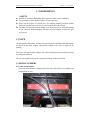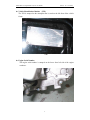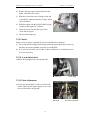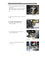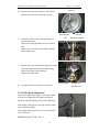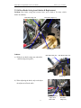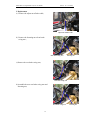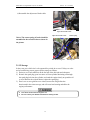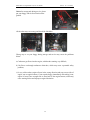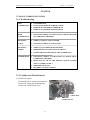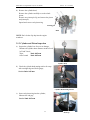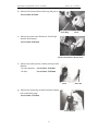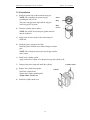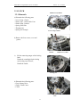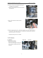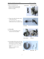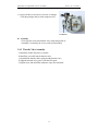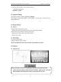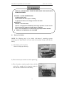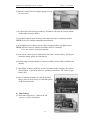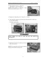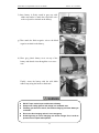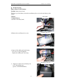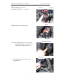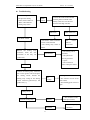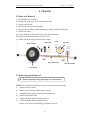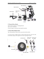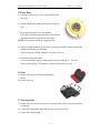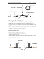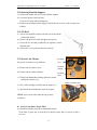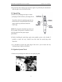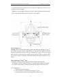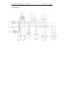
1
Raider Mini 90 (single/double-seat): Service Manual
Version:2.0 Feb. 2006
FOREWORD
This service manual has been specially prepared to provide all the necessary
information for the proper maintenance and repair of the Raider Mini 90.
The Raider Mini 90 fits the needs of a wide variety of users. Those who will be
servicing this Raider Mini 90 should carefully review this manual before performing
any repair or service.
All information, illustrations, photographs and specifications contained in this manual
are based on the latest product information available at the time of publication. Due to
the improvements or other changes, there may be some discrepancies in this manual.
Therefore, if the newest information is requested in the future, please contact us.
We reserve the right to make production changes at any time, without notice and
without incurring any obligation to make same or similar changes for vehicles
previously built or sold.
2
Raider Mini 90 (single/double-seat): Service Manual
Version:2.0 Feb. 2006
CONTENTS
1. GENERAL INFORMATION ---------------------------------------------4
2. MAINTENANCE --------------------- -------------------------------------10
3. ENGINE ----------------------------------------------------------------------21
3.1 ENGINE COMBUSTION SYSTEM-----------------------------------21
3.2 CLUTCH --------------------------------------------------------------------25
3.3 TRANSMISSION /CRANKCASE -------------------------------------27
3.4 FUEL SYSTEM -----------------------------------------------------------29
3.5 ENGINE LUBRICATION & COOLING SYSTEM----------------33
3.6 STARTING FAILURE----------------------------------------------------34
4. ELECTRIC SYSTEM -----------------------------------------------------36
5. CHASSIS ---------------------------------------------------------------------52
Attachment: WIRING DIAGRAM
3
Raider Mini 90 (single/double-seat): Service Manual
Version:2.0 Feb. 2006
1. INFORMATION
SAFETY
z
z
z
Gasoline is extremely flammable and is explosive under certain conditions.
Do not smoke or allow sparks of flames in your work area.
Never run the engine in a closed area. The exhaust contains poisonous carbon
monoxide gas that may cause loss of consciousness and lead to death.
z The battery electrolyte contains sulfuric acid. Protect your eyes, skin and clothing.
If you contact it, flush thoroughly with water and call a doctor if electrolyte gets
in your eyes
1.2 NOTE
All information, illustrations, directions and specifications included in this publication
are based on the latest product information available at the time of approval for
printing.
We reserve the right to make changes at any time without notice and without incurring
any obligation whatever.
No part of this publication may be reproduced without written permission.
1.3 SERIAL NUMBERS
z Frame Serial Number
The frame serial number is stamped under the seat on the frame cross member and
stuck behind the seat.
Frame serial number
4
Raider Mini 90 (single/double-seat): Service Manual
Version:2.0 Feb. 2006
z Vehicle Identification Number (VIN)
The VIN is stamped on the nameplate that is stuck on the left front of the vehicle
frame.
VIN
z Engine Serial Number
The engine serial number is stamped on the lower front left side of the engine
crankcase.
Engine serial number
5
Raider Mini 90 (single/double-seat): Service Manual
Version:2.0 Feb. 2006
1.4 SPECIFICATIONS
DIMENSIONS
Overall Length
Overall Width
Overall Height
Wheelbase
Ground Clearance
VIN
Statutory Plate & Safety Labels
SINGLE-SEAT / DOUBLE-SEAT
1550mm / 1550mm
1000mm / 1100mm
1200mm / 1200mm
1100mm
/ 1100mm
100mm
/ 100mm
Accord with GMVR A01-01
Accord with GB 7258-1997
ENGINE
Model
Type
Engine Capacity
Displacement
Bore×Stroke
Standard Power
Max. Power
Max. Torque
Idle Speed
Idle Speed CO Pollutant
Idle Speed HC Pollutant
Fuel Type
Min. Fuel Consumption
Lubricate Oil Type
Lubrication
Cooling
Ignition
Starting
Spark Plug
Spark Plug Gap
Transmission
1st Forward Gear Transmission Ratio
2nd Forward Gear Transmission Ratio
Backward Gear Transmission Ratio
Compression Ratio
Primary Reduction Ratio
Clutch
Air Cleaner
Gear-Shifting
Valve Gap
Engine Size (Length×Width×Height)
Engine Net Weight
DZIP47FMF
Air-cooled, single cylinder, 4-stroke
90cc
85.8 ml
47mm×49.5mm
3.8/7500 Kw/rpm
4.0 /8000 Kw/rpm
5.7/5500 N.m /rpm
1500±100rpm
≤3.8%
≤800 ppm
SAE 90# or above (unleaded)
367g/kW.h
SAE 15W / 40SF
Pressure & splash
Air-cooled
C.D.I.
Electric
A7RTC
0.6~0.7mm
OHC chain drive
3.182
1.238
2.583
8.8:1
3.416
Wet, multi-plate, friction (automatic)
Filter sponge element
Four gears, hand control
0.05±0.02mm
430mm×320mm×270mm
20.5 kg
6
Raider Mini 90 (single/double-seat): Service Manual
Version:2.0 Feb. 2006
CAPACITIES
Fuel Tank
Engine Oil
Acceleration
Climbing
Top Speed
Turning Radius
Noise Level
Battery
4.5L
0.7~0.9L
≤15s
>180
25km/h
1.7m
≤80dB
12V 8Ah
CHASSIS
Brake System
Front Suspension
Rear Suspension
Front Tire
Rear Tire
Rear disk, foot control
Single A-arm 30 Travel
Swing arm 30 Travel
145/70–6
16X8–7
TIRE PRESSURE
Front
Rear
28 Kpa
50 Kpa
WEIGHT
Net Weight
125kg
/
130kg
***THE SPECIFICATIONS ARE SUBJUET TO CHANGE WITHOUT NOTICE.
1.5 RECOMMENDATIONS
z Fuel
Please use the gasoline of SAE 90# or above.
Also we recommend you to use the unleaded gasoline.
z Engine Oil
Please use the high-quality engine oil of SAE 10w/40SF.
1.2.3 Gear oil
Please use 130# gear oil for reverser gear.
z Break-in Procedure
For your first 2 hours of riding, don’t exceed 2/3 throttles.
Vary the engine speed for the first 5 hours.
Never hold the engine at full throttle for long periods of time.
7
Raider Mini 90 (single/double-seat): Service Manual
Version:2.0 Feb. 2006
1.6 PARTS LOCATION
Double-seat
Single-seat
Seat
Safety Belt
Roll Bar
Rear Rack
Steering Wheel
Control Panel
Rear Wheel
Throttle Pedal
Front Shock Absorber
Brake Pedal
Front Wheel
8
Raider Mini 90 (single/double-seat): Service Manual
Version:2.0 Feb. 2006
Rear View
Rear Rack
Fuel Tank Cap
Fuel Tank
Air Cleaner
Engine
Chain
Reverse lever
9
Muffler
Raider Mini 90 (single/double-seat): Service Manual
Version:2.0 Feb. 2006
2. MAINTENANCE
2.1 MAINTENANCE SCHEDULE
The maintenance interval in the follow table is based upon average riding conditions.
Riding in unusually dusty areas requires more frequent servicing.
Interval
Items
Air cleaner
Spark plug
Carburetor
Gearbox oil
Engine oil
Tire pressure/wear
Brake pad
Drive chain
Brake cable
Chassis
1st Service in
Daily
Monthly
Quarterly
Yearly
X
C
C,A
A
X
R
X
X
CAL
A
X
R
R
A
R
R
X
R
CAL
A
X
R
R
C
R
R
R
R
CAL
A
X
X
A
X
X
A
X
R
A
st
1 Week
X
X
A
X
X
X
X
CAL
A
X
X
X
X
CAL
Fuel switch/fuel tank
Battery
Valve clearance of engine
X
X
Throttle cable
A
A
A
A
Absorber
X
X
X
R
NOTE: X:inspect,clean or replace if necessary ; A: adjust;
C: clean;
L: lubricate;
R: replace.
2.2 Maintenance and Tune-Up Procedures
This section describes the servicing procedures of every item in the Periodic
Maintenance Intervals Table above.
2.2.1 Spark Plug
Clear up the carbon around the spark plug to prevent it from dripping into the cylinder
when removing the spark plug.
Remove the spark plug:
a) In general, it should be carried on after the engine has cooled down;
b) If the spark plug is too tight to remove, spray some rust inhibiter on the spark plug
washer and the thread part; after the inhibiter has soaked the washer and thread
part, rotate the spark plug;
10
Raider Mini 90 (single/double-seat): Service Manual
Version:2.0 Feb. 2006
c) Clear up the filth and carbon
accumulation on the spark plug with a steel
brush or a blade;
d) Inspect the spark plug gap (in general, it should be
about 0.6 - 0.7 mm.);
e) When the carbon accumulation and wear of the
spark plug are too serious, replace the spark plug
with a new one of the same specification.
2.2.2 Tire Pressure / Wear
Check the tire pressure before each of your driving.
The tire pressure is very important for the riding stability.
Specifications: Front Tire: 28 Kpa
Rear Tire: 50 Kpa
Brake Rotor
2.2.3 Brake Performance
a) Check if the brake pad is in good condition;
b) Check the brake rotor for abnormal wear.
z
Brake Cable Adjustment
a) If the brake cable is too loose, adjust the adjust nut
of the brake cable clockwise;
If the brake cable is too tight, adjust the adjust nut
of the brake cable counterclockwise;
If the adjustment doesn’t work, go on with the next
step;
Adjust Nut
b) Loosen the nut M6 at the adjust bolt of the brake
caliper;
If the brake cable is too loose, adjust the adjust bolt
clockwise;
If the brake cable is too tight, adjust the adjust bolt
counterclockwise;
Fasten the nut M6.
Adjust Bolt
11
Nut M6
Raider Mini 90 (single/double-seat): Service Manual
Version:2.0 Feb. 2006
2.2.4 Air Cleaner
Air Cleaner
Clean the air cleaner quarterly, or more often when
driving in dusty conditions.
If the air cleaner is clogged with dust, its performance
will be severely decreased, even the engine damages
will probably be caused.
Inspection and Cleaning of Filters
z
Remove Air Cleaner Cover
Paper Filter
a) Remove the filter from its housing;
b) Lightly tap the filter on an object to knock out the dust;
c) Replace the filter element if it is wrinkled or torn.
z Foam Filter
a) Remove the filter out of its steel cage;
b) Wash the filter in non-flammable cleaning
solvent;
c) Submerge the filter in oil and squeeze it to
remove excess oil;
d) Install the filter element back into the air box.
Air Cleaner
Cover
Air Cleaner
Element
Air Cleaner
Screen
z
Before and during the cleaning, inspect the element for tears; replace it if
z
it’s torn.
Make sure that the element is seated properly and no foreign material can
pass by it
2.2.5 Nuts and Bolts in Chassis
Inspect the nuts and bolts in the chassis during the first week and every month
thereafter.
The nuts and bolts become loose normally after use, please check for the looseness
regularly.
12
Raider Mini 90 (single/double-seat): Service Manual
Version:2.0 Feb. 2006
2.2.6 Tightening Torque Table
Bolt
Diameter
(mm)
4
5
6
8
10
12
14
16
18
Conventional marked bolt
N•m
Kg•m
lb-ft
1-2
1-4
4-7
10-16
22-35
35-55
50-80
80-130
130-190
0.1-0.2
0.2-0.4
0.4-0.7
1.0-1.6
2.2-3.5
3.5-5.5
5.0-8.0
8.0-13.0
13.0-19.0
0.7-1.5
1.5-3.0
3.0-5.0
7.0-11.5
16.0-25.5
25.5-40.0
36.5-58.0
58.0-94.0
94.0-137.5
N•m
1.5-3
3-6
8-12
18-28
40-60
70-100
110-160
170-250
200-280
8.8 marked bolt
Kg•m
lb-ft
0.15-0.3
0.3-0.6
0.8-1.2
1.8-2.8
4.0-6.0
7.0-10.0
11.0-16.0
17.0-25.0
20.0-28.0
1.0-2.0
2.0-4.5
6.0-8.5
13.0-20.0
29.0-43.5
50.5-72.5
79.5-115.5
123.0-181.0
144.5-202.5
2.2.7 Fuel Switch (Petcock)
y Fuel Switch Service
a) Periodically clean the petcock outside with the grease remover and water;
b) Check for any leak or seeping fuel;
c) Replace the petcock if there is any leakage.
z
Fuel Valve Lever
On this vehicle, there is a manually-operated fuel valve
lever with three positions:
a) “ON” position: It’s the normal operating position
where the fuel flows into the carburetor;
b) “RES” position: If the fuel lever is in the “ON”
position and it is too low
for the engine to
operate, turn the fuel lever to the “RES” position to
use the reserved fuel supply, and refuel as soon as
possible;
c) "OFF" position: It’s the closing position. When the
vehicle is not in use, always make sure that the petcock is in the "OFF" position
2.2.8 Engine Oil
Inspect the engine oil before every riding and replace
it monthly.
a) Remove the drain plug from the left side bottom
of the engine, and drain out the left oil into an oil
pan for disposal;
13
Raider Mini 90 (single/double-seat): Service Manual
Version:2.0 Feb. 2006
b) Remove the large cap on the left bottom of the
engine ,and remove the screen;
c) Wash the screen with some cleaning solvent and
reassemble it; make sure that the O-ring is still in
good conditions;
d) Refill the engine with the SAE10W/40SF engine
oil and run the engine for 5 minutes;
e) Check the oil level on the filler cap stick to
assure that it’s proper;
f) Screw back the large cap.
2.2.9 Chassis
Inspect, clean or replace it monthly if necessary and lubricate it quarterly.
a) Grease the chassis bushings and bearings with some grease quarterly to make sure
that they can operate smoothly and enjoy an extended life;
b) If it’s used in extremely wet, muddy or dusty conditions, we recommend you to
service it more often.
2.2.10. A-arm Lubrication
Lubricate the left/right front A-arm periodically.
Left A-arm
Grease Nipple
2.2.11 Chain Adjustment
a) Loosen the 4 bolts M8*16 on the rear wheel axle
holder, and lift up the engine support so as to raise
the rear wheel above the ground;
Bolt M8*16
14
Rear Wheel Axle Holder
Raider Mini 90 (single/double-seat): Service Manual
Version:2.0 Feb. 2006
b) If the chain is too loose, adjust the left and right
rear wheel bearing holders counterclockwise at
the same time;
If the chain is too tight, adjust the left and right rear
wheel bearing holders clockwise at the same
time;
Bearing Holder
c) Fasten the 4 bolts M8*16 on the rear wheel axle
holder.
2.2.12 Brake Shoe Replacement
a) Loosen the connecting clip on the chain;
Remove the chain;
Chain
b) Loosen the adjust nut on the brake cable;
Take out the brake cable;
Brake Cable
Adjust Nut
c) Remove the cotter pin on the bracket of the
rake caliper;
Cotter Pin
15
Bracket
Raider Mini 90 (single/double-seat): Service Manual
Version:2.0 Feb. 2006
Castle Nut
d) Remove the cotter pin, castle nut, left rear tire,
right rear tire and rear wheel hub in order;
Rear Wheel Hub
e) Loosen the 4 bolts on the left/right holder of
the rear wheel axle;
Remove the left/right holder of the rear wheel
axle;
Remove the rear wheel axle together with the
brake caliper assy.;
f)
Remove the lower right connecting bush, bearing
seat of the right rear wheel axle and bearing;
Remove the brake caliper bracket ;
Replace the brake shoe;
g)
Assemble in the reversed order of removal.
Bolt
Cotter Pin
Rear Wheel Axle Holder
Connecting Bush
Bearing Seat of
Rear Wheel Axle
2.2.13 Idle Speed Adjustment
If the rotate speed of the engine is not stable (either
too low or too high) after the engine has started,
adjust the idle speed adjust screw on the carburetor.
If the engine rotate speed is too high, turn the adjust
screw counterclockwise;
If the engine rotate speed is too low, turn the adjust
screw clockwise;
NOTE: Idle Speed: 1500±100r/M
Idle Speed Adjust Screw
16
Raider Mini 90 (single/double-seat): Service Manual
Version:2.0 Feb. 2006
2.2.14 Rear Brake Swing Arm Solution & Replacement
Problem: Rear brake swing arm becomes loose, and is hard to fix when vehicle
brakes in suddenly.
Rear Brake Swing Arm
Rear Brake Caliper Assy.
Adjust Bolt
Fastening Nut
Solution:
a) Weld the rear brake swing arm, adjust bolt,
and fastening nut together ;
Rear Brake Swing Arm
Rear Brake Caliper Assy.
Welding Spot
b) When adjusting the brake, only need adjust
the adjust nut of brake cable .
17
Adjust Nut of
Rear Brake
Brake Cable
Caliper Assy.
Raider Mini 90 (single/double-seat): Service Manual
Version:2.0 Feb. 2006
2. Replacement
a) Remove the adjust nut of brake cable;
Adjust Nut of Brake Cable
b) Remove the fastening nut of rear brake
swing arm ;
Rear Brake Swing Arm
Fastening Nut
c) Remove the rear brake swing arm;
Rear Brake Swing Arm
d) Assemble the new rear brake swing arm and
fastening nut;
Rear Brake Swing Arm
18
Fastening Nut
Raider Mini 90 (single/double-seat): Service Manual
Version:2.0 Feb. 2006
e) Reassemble the adjust nut of brake cable.
Adjust Nut of Brake Cable
Adjust Nut of Brake Cable
Return Spring
Notice: The return spring of brake should be
assembled in the exact direction as shown in
the picture.
Rear Brake Swing Arm
Fastening Nut
2.1.15 Storage
In the event your vehicle isn’t to be operated for periods in excess of 30 days or at the
end of each driving season, prepare for the storage as follows:
1) Drain (or use a fuel stabilizer) all the fuel out of the fuel tank and carburetor;
2) Remove the spark plug; pour one ounce of clean cylinder lubricating oil through
the spark plug hole into the cylinder, and crank the engine slowly to spread the oil
so as to lubricate the cylinder better; replace the spark plug;
3) Don’t save or store gasoline over winter, because the old gasoline has
deteriorated in the winter storage, and will cause hard starting and affect the
engine performance.
z
Don’t drain the fuel while the engine is hot.
z
Be sure to move your BUGGY outside before draining the fuel.
19
Raider Mini 90 (single/double-seat): Service Manual
Version:2.0 Feb. 2006
Notice: In storage and during service, please
put your buggy with its four wheels on the
ground.
Correct
All the other ways are wrong, and should be forbidden.
Wrong
Wrong
Wrong way to set your buggy during storage and service may cause the problems
below:
a) Carburetor gas flows into the engine, which makes starting very difficult;
b) Gas flows out through carburetor drain tube, which may cause a potential safety
problem;
c) In very cold weather, engine oil runs in the wrong direction and stays on one side of
engine, not on engine bottom; if you start the buggy immediately after taking it out,
engine oil won’t have enough time to flow back to the engine bottom, which may
cause starting failure and improper engine lubrication.
20
Raider Mini 90 (single/double-seat): Service Manual
Version:2.0 Feb. 2006
3 ENGINE
3.1 ENGINE COMBUSTION SYSTEM
3.1.1 Troubleshooting
LOW
COMPRESSION
z
z
z
z
CYLINDER HEAD
LEAKAGE OR DAMAGE OF HEAD GASKET
WARPED OR CRACKED CYLINDER HEAD
WORN-OUT CYLINDER OR PISTON RINGS
HIGH
COMPRESSION
z
EXCESSIVE CARBON ACCUMULATION ON PISTON HEAD OR
IN COMBUSTION CHAMBER
EXCESSIVE
NOISE
z
z
WORN OUT PISTON AND CYLINDER
EXCESSIVE CARBON ACCUMULATION
EXCESSIVE
SMOKE
z
z
z
WORN OUT CYLINDER OR PISTON RINGS
IMPROPER INSTALLATION OF PISTON RINGS
SCORED OR CRATCHED PISTON OR CYLINDER WALL
OVERHEATING
z
EXCESSIVE CARBON ACCUMULATION ON PISTON OR IN
COMBUSTION CHAMBER
BLOCKAGE OF AIR TO THE ENGINE COOLING SYSTEM
(FAN, CYLINDER COVER…)
IMPROPER OIL SUPPLY
INCORRECT IGNITION TIMING
z
z
z
3.1.2 Cylinder and Piston Removal
a) Remove the engine;
Disassemble the air cleaner and carburetor;
Remove the intake pipe mounting bolts;
Remove the cylinder head cover;
Cylinder head
Bolt
21
Cylinder head nut
Raider Mini 90 (single/double-seat): Service Manual
Version:2.0 Feb. 2006
b) Remove the cylinder head;
Remove the cylinder carefully to see the whole
piston;
Remove one piston pin clip, and remove the piston
and piston pin;
Spread and remove each piston ring.
Locating pin
Bush
NOTE: Don’t let the clip drop into the engine
crankcase.
3.1.3 Cylinder and Piston Inspection
a) Inspect the cylinder bore for wear or damage;
Measure the cylinder inner diameter at three levels
in X and Y-Axis;
Taper
limit: 0.05 mm
Out of round
limit: 0.05 mm
Cylinder Body
b) Check the cylinder head mating surface for warp
with a straight edge and feeler gauge;
Service limit: 0.05 mm
Cylinder Head Mating Surface
c) Insert each piston ring into the cylinder;
Measure the end gap;
Service limit: 0.45 mm
22
End Gap
Raider Mini 90 (single/double-seat): Service Manual
Version:2.0 Feb. 2006
d) Measure the clearance between the ring and groove;
Service limit: 0.12 mm
Piston Ring
Piston
e) Measure the piston outer diameter at 10 mm high
from the skirts bottom;
Service limit: 49.90 mm
Piston Outer Diameter Measurement
f)
Measure the piston pin bore, and the piston pin outer
diameter;
Pin outer diameter: Service limit: 12.98 mm
Pin bore:
Service limit: 13.055mm
Piston
Piston Pin
g) Measure the connecting rod small end inner diameter
with a small hole-gauge.
Service limit: 13.10 mm
Connecting Rod
23
Raider Mini 90 (single/double-seat): Service Manual
Version:2.0 Feb. 2006
3.1.4 Installation
a) Install the piston rings with the marks facing up;
NOTE: Do not damage the piston rings by
spreading the ends too far.
The piston ring gap must align with the ring pin
in the ring groove of piston.
Piston
Ring
b) Clean the cylinder gasket surface;
NOTE: Be careful. Do not drop any gasket material
into the crankcase.
Ring
Groove
c) Apply some oil to the inside of the connecting rod
small end;
d)
Install the piston, piston pin and clip;
Install the piston with the arrow mark facing the exhaust
pipe;
NOTE: Do not align the piston pin clip end gap with the
piston cutout
e) Install a new cylinder gasket;
Apply a thin coat of engine oil to the piston rings and cylinder wall;
f)
Compress the piston rings and install the cylinder;
g)
Replace the cylinder head gasket;
Install the cylinder head;
Tighten the cylinder-mounting bolt;
Torque Value: 15-18 N. m.
Cylinder Gasket
Cylinder
h) Install the cylinder head cover.
24
Raider Mini 90 (single/double-seat): Service Manual
Version:2.0 Feb. 2006
3.2 CLUTCH
Plank Cover, Limited
3.2.1 Dismantle
a) Dismantle the following parts:
---Lever Comp., Clutch
---Plate Comp. , Clutch Lifter Cam
---Plank Comp., Limited
---Spring, Plate Side
---Through, Oil
---Spring, Oil Through
Lever Comp., Clutch
b) Remove the four screws, cover and
gasket;
Clutch
Clutch Cover, Outer
c) Lift the connecting tongue of the locking
bush;
Detach the centrifugal clutch locking
nut by using a special tool ;
Detach the clutch;
Locking Nut
d) Dismantle the following parts:
---Gear, Primary Drive
---Guide, Clutch Center
---Collar
Gear
25
Raider Mini 90 (single/double-seat): Service Manual
Version:2.0 Feb. 2006
e) Dismantle the following parts:
---Circlip, External
---Gear, Primary Drive
Circlip
3.2.2 Troubleshooting
When the engine works at the idle speed, the vehicle moves slowly.
z The clutch has not been adjusted properly;
z The clutch disc is warped;
z The clutch lock nut is loose;
z There is too much oil in the crankcase;
z The clutch rod has not been installed correctly.
When accelerating, the clutch slips.
z The clutch has not been adjusted properly;
z The clutch disc is worn out;
z The clutch spring is loose;
z The gearshift oil is mixed with copper or graphite additive.
26
Gear
Raider Mini 90 (single/double-seat): Service Manual
Version:2.0 Feb. 2006
3.3 TRANSMISSION /CRANKCASE
3.3.1 Trouble Shooting
Difficulty in gearshift:
z The clutch was not adjusted properly;
z The gear shifter is bent;
z The guide pin is broken;
z The gear guard is worn out.
Transmission dislocation:
z The guide pin is worn out;
z The gear shifter is bent.
Too much noise:
z The shaft neck bearing is worn out;
z The transmission bearing is worn out.
27
Raider Mini 90 (single/double-seat): Service Manual
Version:2.0 Feb. 2006
Engine vibration:
z The crankshaft radial run-out is too great.
3.3.2 Transmission Device Assembly
Assemble the transmission device by reversing the disassembly procedure.
NOTE: Align the head of the snap ring with the center of the key slot as shown in the
picture.
3.3.3 Path of Power Transmission
a)
b)
c)
d)
e)
The torque of crankshaft drives the clutch.
The torque of clutch transmits the main shaft by gear.
The torque of main shaft transmits the counter shaft by gear.
The counter shaft drives the small sprocket.
The small sprocket drives the rear sprocket by chain, and transmits the rear-axle
shaft to move the rear wheel.
28
Raider Mini 90 (single/double-seat): Service Manual
Version:2.0 Feb. 2006
3.4 FUEL SYSTEM
3.4.1
Trouble Shooting
ENGINE
STARTING
DIFFICULTY
z
z
z
z
z
NO FUEL IN TANK
NO FUEL TO CYLINDER
TOO MUCH FUEL IN CYLINDER
NO SPARK AT SPARK PLUG
CLOGGED AIR CLEANER FILTER
UNSTEADY,
STALLING
OR
POORLY-RUNNING
ENGINE IDLES
z
z
z
z
z
z
IMPROPER ADJUSTMENT OF IDLE SPEED SCREW AT
CARBURETOR
IGNITION MALFUNCTION
TOO LEAN OR TOO RICH FUEL/AIR MIXTURE
DIRTY AIR CLEANER
INSULATOR LEAKAGE
CLOGGED BREATHING HOLE OF FUEL TANK CAP
z
z
z
z
z
CLOGGED FUEL JET OF CARBURETOR
CLOGGED TREATHING HOLE OF FUEL TANK CAP
CLOGGED FUEL FILTER
UNSMOOTH FLOWING OF FUEL IN THE TUBE
TOO LOW FLOAT LEVEL IN CARBURETOR
z
z
z
z
FAULTY FLOAT NEEDLE VALVE IN CARBURETOR
TOO HIGH FLOAT LEVEL
CLOGGED AIR DUCT IN CARBURETOR
DIRTY AIR CLEANER
LEAN
MIXTURE
RICH
MIXTURE
z The carburetor can’t start, or becomes difficult to start.
Reason Analysis: After the tryout, the carburetor has been exposed in the air for a
long period, so that a layer of mucous membrane has formed and blocked the main jet.
As a result, the oil can’t flow smoothly and the engine starting becomes difficult, or
the engine stops soon after starting.
Solution
a) Check if there is any damage or leakage on the
pressurized tube of oil cock;
Pressurized Tube
29
Raider Mini 90 (single/double-seat): Service Manual
Version:2.0 Feb. 2006
b) Clean the carburetor and readjust the idle speed
according to the steps below:
Open the connecting tube between the air cleaner
and carburetor.
Air Cleaner
c) Spray a little carburetor cleanser into the
carburetor.
Spray Cleanser
d) Start the engine and run for a while, then quickly step on the throttle pedal for
several times .If the engine works well, assemble the connecting tube; otherwise,
repeat the steps above several times.
Readjust the idle speed if it is unstable.
3.4.2 Carburetor
z Removal
a) Remove the air cleaner;
Disconnect the fuel line;
Unscrew the intake pipe mounting bolts
at the carburetor, and then remove the
carburetor;
30
Intake Tube
Carburetor
Raider Mini 90 (single/double-seat): Service Manual
Version:2.0 Feb. 2006
b) Remove the carburetor cap;
Remove the throttle cable from the
throttle valve while depressing the
throttle valve spring;
Throttle Cable
Throttle Valve Spring
c) Remove the needle clip retainer, the jet
needle and needle clip;
Inspect the throttle valve and the jet
needle surface for wear, scratches or dirt.
Jet Needle
z Disassembly
a) Unscrew the float chamber screws
and remove the float chamber:
Float Chamber
Carburetor
b) Disassemble the float arm pin, float and
float needle valve. Inspect the seat of the
float needle valve for wear or damage:
Disassemble the idle jet, main jet, idle
speed;
Adjust screw and idle mixture
adjustment screw:
Float
31
Float Needle
Pin
Raider Mini 90 (single/double-seat): Service Manual
Version:2.0 Feb. 2006
c) Inspect all the jets and screws for wear or damage;
Clean the passages and jets with compressed air.
Carburetor
z
Assembly
Clean all parts in solvent and blow it dry with compressed air.
Assembly is essentially the reverse order of disassembly.
3.4.3 Throttle Valve Assembly
a) Install the needle clip on the jet needle;
b) Install the jet needle into the throttle valve;
c) Assemble the throttle cable, spring and the throttle valve;
d) Align the throttle valve groove with the idle speed;
e) Adjust screw and install the carburetor cap to the carburetor.
32
Raider Mini 90 (single/double-seat): Service Manual
Version:2.0 Feb. 2006
3.5. ENGINE LUBRICATION & COOLING SYSTEM
3.5.1 Troubleshooting
z
z
INSUFFICIENT OIL SUPPLY z
TO ENGINE
z
z
z
TOO LOW OIL LEVEL IN OIL TANK
IMPROPER FIXED OIL TUBES
OIL LEAKAGE FROM TUBE ENDS
DAMAGED OIL TUBES
CLOGGED OIL TUBES
BROKEN-DOWN OIL PUMP
z
ALWAYS INSUFFICIENT OIL z
LEVEL
z
EXTERNAL OIL LEAKAGE
WORN CYLINDER HEAD GASKET
WORN PISTON RINGS
ENGINE ALWAYS RUNS HOT
z
z
IMPROPER ADJUSTMENT OF OIL
PUMP
POOR OIL QUALITY
3.5.2 Caution
Supplying enough oil to the engine is very important. If the oil quantity is not enough,
the engine will be severely scored and will most likely seize the motor.
When the upper end of the engine is in need of replacement, change the piston, piston
rings, piston pin clips, and the cylinder all at the same time.
3.5.3 Cooling System
When the buggy is running, the wind blowing towards it will cool down the cylinder
head and cylinder body through the cooling fins. So, the cylinder and piston will not
overheat.
The cooling fins should be kept clean.
33
Raider Mini 90 (single/double-seat): Service Manual
Version:2.0 Feb. 2006
3.6 Starting Failure
34
Raider Mini 90 (single/double-seat): Service Manual
Version:2.0 Feb. 2006
35
Raider Mini 90 (single/double-seat): Service Manual
Version:2.0 Feb. 2006
4. ELECTRIC SYSTEM
4.1Troubleshooting
ENGINE STOPPING
AFTER STARTING
z
z
IMPROPER IGNITION TIMING
FAULTY SPARK PLUG
NO SPARK AT PLUG
z
z
z
z
z
ENGINE STOP SWITCH AT “OFF”
FAULTY IGNITION COIL
FAULTY GENERATOR
FAULTY CDI UNIT
POOR CONNECTION:
Between CDI and Ignition Coil
Between Alternator and CDI Unit
Between CDI and Engine Stop Switch
Between Ignition Coil and Spark Plug
Between Generator and CDI Unit
POOR RUNNING OF ENGINE AFTER
STARTING
z
PRIMARY IGNITION CIRCUIT TROUBLE:
Faulty Generator
Faulty CDI Unit
Faulty Alternator Exciter Coil
Loose Connect ion between Terminals
Faulty Ignition Coil
SECONDARY IGNITION CIRCUIT TROUBLE:
Faulty Plug
Loose Connect ion at Spark Plug Wires
IMPROPER IGNITION TIMING:
Faulty Generator
Faulty CDI Unit
z
z
z
z
z
LOOSE, BROKEN OR SHORT WIRES
FAULTY ALTERNATER
FAULTY IGNITION SWITCH
INTERMITTENT ENGINE POWER
z
z
LOOSE BATTERY CONNECTION
LOOSE CHARGING SYSTEM CONNECTION
STARTER
FAILURE
z
z
z
DEAD BATTERY
FAULTY IGNITION SWITCH
LOOSE OR DISCONNECTED WIRES
CHARGING SYSTEM FAILURE
MOTOR
TURNING
36
Raider Mini 90 (single/double-seat): Service Manual
Version:2.0 Feb. 2006
(When Starter Motor And Engine Can
Turn)
ENGINE STARTING FAILURE
z
z
z
FAULTY IGNITION SYSTEM
SLOW MOVEMENT OF STARTER
z
z
FAULTY ENGINE STOP SWITCH
OVERLOW
ELECTROLYTE
SPECIFIC
GRAVITY IN BATTERY or USED UP BATTERY
POOR CONTACT BETWEEN CONNECTING
TERMINALS OF BATTERY WIRES
BROKEN STARTING RELAY
POOR GROUNDING OF BATTERY
BROKEN STARTER BRUSH
z
z
z
z
(When the starter runs,)
ENGINE FAILURE
z
z
z
ENGINE PROBLEMS
ELECTRIC STARTER RUNNING IN
INVERTED ORDER:
Improper Assembly Of Starter Case
Improper Connection Of Terminal
BROKEN STARTING RELAY
BROKEN DRIVE CHAIN OF STARTER
AN
KATA SOUNDS FROM STARTING (DUE TO ENGINE PROBLEM) FAILURE OF
RELAY
SWITCH
&
ENGINE CRANKSAHFT MOVEMENT
FAILURE
4.2 Ignition Coil
a) Remove the spark plug cap from the spark plug;
Disconnect the primary ignition coil wire;
Ignition Coil
b) Measure the primary coil resistance;
Standard: 0.1-1.0 Ω
37
Ignition Coil
Raider Mini 90 (single/double-seat): Service Manual
Version:2.0 Feb. 2006
c) Measure the secondary coil resistance with the
spark plug cap in place.
Standard: 7-9 KΩ
4.3 Ignition Timing
The ignition advance is 15º± 1º B.T.D.C /1700rpm.
The Capacitive Discharge Ignition (CDI) system is factory pre-set and does not
require adjustment.
4.4 Starter Motor
z Remove
a) Remove the left crankcase cover;
Remove the snap ring from the follower gear of the electric starter;
b) Pull off the wire connector of the electric starter;
Remove the 3 bolts; remove the electric starter;
Remove the O-ring.
z Disassembly
a) Remove all the bolts;
b) Disassemble the electric starter.
NOTE: Assemble the starter back with the same amount of washers.
4.5 Battery
z
Initial Service
z The following procedure is very dangerous and should be performed with
utmost care and attention. Wear protective eyewear, rubber gloves, and have
water available should electrolyte come in contact with skin or eyes.
38
Raider Mini 90 (single/double-seat): Service Manual
Version:2.0 Feb. 2006
KEEP ALL CHILDREN AWAY FROM THE AREA WHILE THIS PROCEDURE IS
BEING PERFORMED.
z POISON – CAUSES SEVERE BURNS
Contains sulfuric acid.
Avoid contact with skin, eyes, or clothing
TO prevent accidents, rinse empty container with water.
z ANTIDOTE:
External – flush with water;
Internal – call physician immediately. Drink large quantities of water or milk.
Follow with milk of magnesia, beaten eggs or vegetable.
Eyes – Flush with water for 15 minutes and get prompt medical attention.
z KEEP OUT OF THE REACH OF CHILDREN
z
Battery Installation
NOTE: The following page is for vehicles with battery’s containing separate
electrolyte pack. Most battery’s will come with the electrolyte already sealed into the
battery.
a) Place battery on level surface;
Remove sealing tape from top;
b) Take the electrolyte container out of the plastic bag;
c) Place electrolyte container upside down with the
sealed silver mouths of the electrolyte bottles in
line with the six filler holes of the battery;
39
Raider Mini 90 (single/double-seat): Service Manual
Version:2.0 Feb. 2006
d) Push the container down strongly enough to break
the silver seals;
e) As electrolyte starts flowing into battery, air bubbles will come up from the mouths
of the plastic electrolyte bottles;
f) Leave bottles upside down in battery holes until electrolyte is completely drained;
NOTE: Never leave children unattended around battery.
g) If air bubbles cease to float to the top of the electrolyte bottles, tap lightly on top;
NOTE: DO NOT remove container from battery while it is draining.
.
Never cut or pierce electrolyte container.
h) After all the electrolyte has drained from the bottles into the battery, pull plastic
electrolyte bottles gently out of the battery;
i) Discard empty electrolyte bottles in a waste area that is inaccessible to children and
animals;
j) After filling, let battery stand for at least 30 minutes before charging (This allows
the electrolyte to penetrate plates for optimum performance and ensures longer
battery life);
k) After 30 minutes the battery is ready for its initial
charge, place cap strip loosely over the filling holes
as shown in the picture.
z Initial Charge
a) Connect the red positive (+) cable to the red
positive (+) pole of the battery;
40
Raider Mini 90 (single/double-seat): Service Manual
Version:2.0 Feb. 2006
b) Connect the black negative (-) cable to the
black negative (-) pole of the battery;
NOTE: The red positive (+) cable has a larger
diameter than the black negative y cable.
c) Charging rate: Charge battery @ 0.7 Amps for 5 ~ 10 hours;
d) After charging is complete, press down firmly with both hands to seat the caps.
Do not pound or hammer.
The battery is now sealed;
.
NEVER REMOVE THE STRIP OF CAPS NOR ADD ANY WATER OR
ELECTROLYTE.
e) Install battery into battery tray making sure that the
rubber mat is in place;
NOTE: The warning label on the battery should be
facing the warning label on the gray tray.
41
Raider Mini 90 (single/double-seat): Service Manual
Version:2.0 Feb. 2006
f) Once battery is firmly seated in gray tray with
rubber mat under it, attach the red positive wire
to the red positive terminal on the battery;
g) Then attach the black negative wire to the black
negative terminal on the battery;
.
h) Place grey plastic battery cover on top of the
battery and thread wires through the cover cuts –
outs.
Finally, secure the battery with the wide black
rubber strap using the hooks on both ends.
.
z
DO NOT open sealed caps to add water to battery.
z
Always wear safety glasses and charge in a ventilated area.
z
If battery gets hot to the touch, discontinue charging and allow battery to
cool down.
z
Do not use fast charging unless it is an emergency.
z
At the beginning or end of charging, turn off the charger first, in order to
prevent electric spark and explosion.
42
Raider Mini 90 (single/double-seat): Service Manual
z
z
Version:2.0 Feb. 2006
Charge in a well ventilated area.
DO NOT smoke around batteries and keep away from open flame.
z Battery Replacement:
a) Remove old battery;
Mark which cable is connected to the positive terminal (+) and which cable is
connected to the negative (-) terminal;
b) Clean cable connectors with wire brush or sandpaper to remove oxidation;
c) After charging, install new battery;
Put dielectric grease on the battery terminals to avoid corrosion;
d) Connect cables to the proper terminals: positive cable to positive terminal, and
negative cable to negative terminal;
NOTE: Positive (+) cable is red and larger in diameter; Negative y cable is black and
smaller of the two in diameter.
CONNECT NEGATIVE CABLE LAST.
e) Torque terminal bolts to 40 in. / lbs;
f) Place rubber pad in bottom of battery tray;
. Securely fasten battery to the vehicle using cover and strap.
z
To avoid possibility of explosion, always connect battery cable in the
order specified:
RED first;
BLACK last. An exploding battery can cause serious
injury or death.
z
Batteries contain sulfuric acid.
z
Always shield eyes with protective eyewear when working around
battery acid.
z
z
Battery acid is poisonous and can cause severe burns.
DO NOT smoke around batteries and keep away from open flame.
43
Raider Mini 90 (single/double-seat): Service Manual
Version:2.0 Feb. 2006
Trouble Shooting
Battery Short Circuit Solution
Problem: battery short circuit
z
Purpose: to prevent battery electrodes touch battery box cover and cause battery short
circuit
Solution:
Battery Band
1. Inspect Battery
a) Remove the battery band;
Steel Battery Box Cover
b) Remove the steel battery box cover;
Rubber Pad
c) Inspect if the rubber pad in the battery
box cover is in good condition;
Replace the rubber pad if necessary;
e) Suggest to replace the steel battery box
cover with a plastic one
(part no. 50320-BDD0-0000 ).
.
44
Plastic Battery Box Cover
Raider Mini 90 (single/double-seat): Service Manual
Version:2.0 Feb. 2006
2. Replace Battery Box Cover
a) Assemble the battery + /- electrode;
+ Electrode
-
Electrode
Battery
b) Put the battery into the battery box;
Tel.: (8
Battery Box
Plastic Battery Box Cover
c) Put on the plastic battery box cover (part no.
50320-BDD0-0000), or add one rubber
pad in the steel battery box cover;
Battery Band
f)
Put the battery band on the battery, and
fasten the band;
45
Raider Mini 90 (single/double-seat): Service Manual
Version:2.0 Feb. 2006
Replaced Battery Box Cover
e) The replacement is finished.
4.6 Starter Motor / Starting Clutch
4.6.1 Starter Motor
z Maintenance Warning
Turn off the ignition switch before maintaining the electric starter. The sudden
starting of the electric starter could cause severe injuries or death.
a) If the battery can’t provide enough electric charges, the electric starter can’t run
fast enough, or the provided ignition currents are not enough.
b) If the electric starter is started continually when the engine can’t work, the electric
starter will be damaged.
46
Raider Mini 90 (single/double-seat): Service Manual
z
Version:2.0 Feb. 2006
Spec.
Item
Length of electric starter carbon brush
Standard value
12.0mm
Unit: mm (in)
Limit value
4.0mm
z Trouble Shooting
NOTE: Check the following items before looking
for the system failure:
a)
b)
c)
If the main fuse has been burned (10A);
If the wire of the battery or electric starter
has
got loose;
If the battery is leaking.
The electric starter doesn’t work
Undercharged: Below 12.0 V
z Check
a) Check the carbon brush and measure the length of the brush;
Limit value: 4.0mm
b) Check if the rectifier bar has depigmentized;
The depigmentation of couples of rectifier bars shows the armature coil has
earthed;
NOTE: The rectifier bar can’t be burnished by emery cloth or sand paper.
c) Check the connectivity between couples of rectifier bars;
Check the connectivity between the rectifier bar and the armature shaft;
Rectifier bars: connected;
Armature ---shaft: disconnected;
d) Check the connectivity between the cable terminal and the black wire brush;
Check the connectivity between the cable terminal and the electric starter shell;
If the connecting wire is broken or disconnected with the starter shell, the wire
needs repairing.
Cable terminal --- starter shell: disconnected;
Cable terminal ---brush: connected.
Electric Starter
z Assembly
a) Assemble the electric starter;
Align the carbon brush pin with the shell groove;
47
Raider Mini 90 (single/double-seat): Service Manual
Version:2.0 Feb. 2006
b) Align the rear shell groove with the carbon brush pin;
Install the rear shell;
c) Check if the O-ring is in good condition; replace it if it is defective.
Lubricate the O-ring;
Install the electric starter and fasten the bolt;
Connect the connector of the electric starter;
d) Install the snap ring into the shaft groove;
Install the left crankcase cover.
4.6.2 Starting Clutch
z Remove Main/Follower Sprocket
a) Remove the following parts:
--- Flywheel;
---Drive chain slide plate
---Screw and locating plate;
---Snap ring;
b) Remove the starting chain and sprocket
Assembly:
c) Install by reversing the dismantling procedure.
z Remove Starting Clutch
a) Remove the 3 screws and starting clutch
shell;
b) Remove the roller, spring cap and spring.
Starting Clutch
Shell
z Check
a) Check if the roller runs smoothly;
Check if the roller has been over abraded;
48
Raider Mini 90 (single/double-seat): Service Manual
Version:2.0 Feb. 2006
b) Check the abrasion and damage of the
Main/follower sprocket and chain:
Measure the outer diameter of the main
Sprocket.
z Assembly
a) Install the starting clutch shell;
Apply the locking agent to the screw
threads of the starting clutch shell;
Install the screws and fasten them;
b) Put a mark on every screw of the clutch
shell;
c) Install the spring, spring cap and roller;
49
Raider Mini 90 (single/double-seat): Service Manual
Version:2.0 Feb. 2006
4.6.3 Starting Relay
z System Check
a) Turn on the ignition switch;
Press the starting switch;
It is normal if the starting relay makes
“Kata” Sounds.
b) Pull out the connector from the starting
relay;
Measure the voltage of the connection
terminal;
Check the connectivity of the connection
terminal;
Item
Starting relay coil
Connection Terminal
Yellow/red wire and
ground wire
Battery voltage Black
wire(+)and
input wire
ground wire(-)
Electric
starter Red wire (+)and ground
input wire
wire(-)
Technical Criterion
Turn on the starting switch: it
should be connected.
Turn on the ignition switch: the
battery should be connected.
The battery should be connected.
z Elements Check
a) Connect a DC12V battery between the black wire and yellow/red wire;
b) Connect an ohmmeter between the red wire and red/white wire of the starting
relay; at this time, the circuit should be connected;
c) If the circuit is disconnected, replace the starting relay.
50
Raider Mini 90 (single/double-seat): Service Manual
z
Version:2.0 Feb. 2006
Troubleshooting
Turn on the ignition switch
and press the starting
switch; check if there is a
“Kata” sound from the
starting relay switch.
Connect the electric starter terminal
with the positive terminal of the
battery (a thin wire can’t be used
because of the high currents).
“Kata”
sounds
Starter runs.
Starter doesn’t run.
No “Kata” sounds
---The electric starter connector
is loose or disconnected;
---The starting relay switch is
broken.
Remove the starting relay
connector; check the wire
connection of the relay coil
(yellow/red).
Disconnected
Connected
Connect the starting relay connector,
turn on the ignition switch and press
the starting switch; measure the
starting relay voltage at the starting
switch connector [yellow/red(+) and
ground wire(-) ].
No
voltage
The
electric
starter is
out of order.
---The starting switch
is broken;
---The yellow/red
wire or green wire
is open;
---The connector is
loose or has poor contact.
---The ignition switch is broken;
---The connector is loose or has
poor contact;
---The bundling point of wires is
open.
Voltage exists
Check the starting relay
51
Normal
---The connector is loose
or has poor contact;
Abnormal
---The starting relay
is defective.
Raider Mini 90 (single/double-seat): Service Manual
Version:2.0 Feb. 2006
5. CHASSIS
5.1 Rear Axle Removal
a)
b)
c)
d)
Disassemble the rear Wheel.
Remove the cotter pins on the rear wheel axle nut.
Remove the axle nut.
Block up the rear end of the machine.
e)
f)
g)
h)
Remove the rear wheel and hub assembly by sliding off splines of the axle.
Remove the chain.
Loosen the nuts on the bearing carrier, and remove the bolts.
Remove the axle and bearing carriers as a unit.
i) Remove the brake caliper bolt and brake caliper/
Brake Caliper
Brake Disc
Chain
Rear Wheel Axle
Sprocket
Rear Wheel Hub
Rear Wheel
5.2 Rear Swing Arm Removal
z
Please operate properly according to the instructions.
NOTE: The swing arm, axle and motor can be removed as a unit if needed.
a) Remove the rear. shock.
b) Remove the rear brake caliper, and set it aside.
c) Unplug the brake light wiring from the electrical box.
d) Remove the throttle cable.
e)
f)
Remove the bolts from the swing arm pivot
Check the buffer rubber bushing for wear;
If there is any wear on the bushing, it should be replaced.
52
Raider Mini 90 (single/double-seat): Service Manual
Version:2.0 Feb. 2006
Rear Swing Arm
Shock Absorber
Chain Guard
Electric Box
Cover
Battery
5.3 Front & Rear Shocks
The front and rear shocks are oil dampened units.
They are non-re-build able.
If any oil seepage is noticed, the shock should be replaced.
5.4 Front Wheel Replacement
Don’t disassemble the castle nuts when you replace the front wheels.
It is only necessary to tighten the nuts so that the wheel turns freely on the axle with
the minimum end play. Please tighten the nuts after replacing the wheels.
Shock Absorber
Front A-arm
Assy., Left
Front A-arm
Assy., Right
Front Wheel
Front Wheel Hub
53
Steering Knuckle
Raider Mini 90 (single/double-seat): Service Manual
Version:2.0 Feb. 2006
5.5Front Hubs
a) Check the seals for rips or tears, and replace them if
any exist.
b) Remove the bearings with a punch from the opposite
side.
c) Inspect the bearings for easy movements;
If any dirt or mud has gotten into them, wash them in
the cleaning solvent and spin with your finger.
NOTE: Never spin them with the compressed air.
d) Apply an ample amount of grease to the bearing and reinstall it with a bearing tool,
making sure that they go in straight;
If the bearing isn’t straight, damages to the hubs can occur.
e) Install the seals into the hubs;
It is recommended to apply a small amount of grease to the lip of the seal;
If the retention spring is in bad shape, replace the seal with a new one.
5.6 Seat
a) Remove all the nuts and bolts underneath the
seat rail.
b) Remove the seat.
5.7 Steering Shaft
a) Remove the nuts on the steering block, and grease the inside of the steering block
periodically.
b) Loosen the steering shaft and clamp nut on the steering gear box.
c) Remove the steering shaft.
54
Raider Mini 90 (single/double-seat): Service Manual
Version:2.0 Feb. 2006
Steering Comp.
Steering Shaft
Steering Ball Joint, Right
Steering Ball Joint, Left
Dust Cover
Steering Gear
5.8 Steering Gear Box and Ball Head
a) Remove the four bolts of the LH&RH clamp nuts on the steering gear box.
b) Remove and check the ball head dust cover on the steering gear box for wear.
c) Check the steering cover on both sides of the steering gear box and grease the ball
head.
d) Fill the steering gear box with Grease after cleaning the dust; It is recommended
to replace the ball joint if it is loose or not smooth.
5.9 Throttle & Brake Pedal
a) Remove the throttle, throttle pedal and axle nut.
b) Check the throttle and brake pedal for signs of wear;
Replace if any wear is present.
c) Before installation, apply enough grease on the throttle and brake pedal in order to
make them swing more flexibly.
Throttle Pedal
Pedal Link Bolt
Brake Pedal
Pedal Link Bolt
Spring
55
Raider Mini 90 (single/double-seat): Service Manual
Version:2.0 Feb. 2006
5.10 Steering Knuckle Support
a) Remove the rubber dust cover of the knuckle support.
b) Check the grease of the ball joint;
Clean it if it’s dirty and fill with grease.
c) Replace the steering knuckle support if the ball joint is loose or the steering isn't
flexible
5.11 Tie Rod
a) The tie rods should be checked for the ease of movement
in their full rotation.
b) Remove the protective boot and apply some grease.
c) Check the tie rod ends periodically for tightness at their
adjusting nuts.
d) Always use a new cotter pin after the removal.
5.12 Service Air Cleaner
Air Cleaner
Service the air cleaner every 100 hours.
Cover
a) Remove the air cleaner cover;
Air Cleaner
Element
b) Remove the air cleaner element;
Air Cleaner
Screen
c) Fill the non-flammable cleaning agent into a basin
and dip the element in it;
Remove Air Cleaner Cover
e) Dry it after cleaning, and dip it into the engine oil
f) specified by the manufacturer, then dry it again.
NOTE: Service more often when driving in dusty
conditions.
z Service Foam Filter / Paper Filter
a) Clean the foam filter with the no-flammable cleaner;
If the filter is paper, tap it on an object to knock out the dust, or replace it with a
new one.
56
Raider Mini 90 (single/double-seat): Service Manual
Version:2.0 Feb. 2006
b) Dry the filter after cleaning, dip it into the engine oil specified by the manufacturer
and wring the excess oil out of the filter.
5.13 Spark Plug
a) Remove the spark plug and inspect it with a
spark plug wrench each time you change the oil;
If possible, check the spark plug gap (the area
between the two electrodes)with a wire feeler
gauge, and this specification should be
0.6-0.7mm.
NOTE: The electrodes should be kept clean and
free of carbon. The presence of carbon or excess
oil will greatly deter the proper engine
performance.
b) Before installing the spark plug, apply some graphite grease on the threads if
possible to ensure the easy removal next time when the spark plug needs
inspection.
c) It is advisable to replace the spark plug at least once a year to insure the easy
starting and good engine performance.
5.14 Ignition System Check
1. Remove the spark plug and reattach it to the spark plug lead.
57
Raider Mini 90 (single/double-seat): Service Manual
Version:2.0 Feb. 2006
2.Push the electric button “START” ( Yellow button). Apply the rear brake lever to
make sure the rear wheels are locked. If the ignition system is operating properly, a
blue mark should jump across the spark plug gap. If there is no spark, take your
machine to your service center.
Performing the spark test improperly could be hazardous.
You could get a higher voltage electrical shock if you are not familiar with this
procedure.
Do not perform this check if you are not familiar with the procedure. Do not point the
spark plug near the spark plug hole during this test. Do not do this test if you have a
heart condition or wear a pacemaker. Do not perform this test is any near any open fuel
containers for near fuel which has spilled on the ground, on the engine, or any part of
the ATV.
COMPLAINT: Engine stalls
1.
Make sure there is enough fuel in the fuel tank.
2.
Check to see that the spark plug is not fouled. Removed the spark plug and clean
it. Replace it, if necessary.
Make sure the fuel valve is not clogged, and the fuel tank is not clogged, either.
Check the idle speed. If necessary, adjust it using a tachometer. The correct idle
3.
4.
speed is 1400~1600r/min.
5.15 Front Wheel Alignment
a) The front wheels should be "toed-in" from 1/8" to 1/4"; for the proper toe-in
dimension, Dimension A should be 1/8"-1/4"longer than Dimension B.
b) Check the alignment measure distance from A /B to the centerline (CL) of the
tires with the wheels pointed straight ahead.
c) Loosen the lock nuts on both sides of the front tie rods;
58
Raider Mini 90 (single/double-seat): Service Manual
Version:2.0 Feb. 2006
To make Dimension B shorter, screw the rod left; if Dimension B needs to be
longer, screw the rod right;
Tighten the jam nut tightly against the rod end, recheck the distance and repeat the
above steps until the Dimensions are the same as the required.
5.16 Gearshift Lever
Caution: Proper operation of this vehicle requires that the driver shift from 1st into 2nd
gear. When the engine reaches a high RPM in 1st gear, the driver should release the
accelerator pedal and push the shift lever forward into 2nd gear. Then, press back
down on the accelerator pedal to continue driving forward. Failure to properly shift
may result in engine overheating, which may damage the engine and poses a fire
hazard.
How to shift from 1st into 2nd gear:
1) When the vehicle is running, stepping on the accelerator pedal provides
acceleration…UNTIL the limit of speed in 1st gear has been reached. At this point
the vehicle will no longer accelerate in speed, and the engine will be very loud.
2) To change gears:
a. Release the accelerator pedal;
b. Press the shift lever forward until it engages 2nd gear;
c. Press back down on the accelerator pedal to resume driving.
59
Raider Mini 90 (single/double-seat): Service Manual
Version:2.0 Feb. 2006
Wiring diagram:
60