1
Zeus Parallel ATA (PATA)
2.5-Inch Solid State Drive
Product Datasheet
Export Administration Regulations
This document may contain technical data controlled by the U.S. Export Administration Regulations, and
may be subject to the approval of the U.S. Department of Commerce prior to export. Any export, directly or
indirectly, in contravention of the U.S. Export Administration Regulation is prohibited.
Trademark Information
The STEC name, logo and design are trademarks of STEC Inc. No right, license, or interest to such
trademarks is granted hereunder, and you agree that no such right, license, or interest shall be asserted by
you with respect to such trademark. Other product and corporate names mentioned in this document are
used for identification purposes only and may be trademarks or registered trademarks of their respective
companies.
Disclaimer of Liability
The performance information and specifications furnished in this document reflect the engineering
development objectives of STEC Inc. and should be used for comparative analysis and reference purposes.
The content of this document is accurate as of the date of this publication; however, the information
contained herein, including but not limited to any instructions, descriptions and product specifications, is
subject to change without prior notice.
STEC INC. (STEC) PROVIDES NO WARRANTY WITH REGARD TO THIS DOCUMENT OR
ANY OTHER INFORMATION CONTAINED HEREIN AND HEREBY EXPRESSLY DISCLAIMS
ANY IMPLIED WARRANTIES OF MERCHANTABILITY OR FITNESS FOR ANY
PARTICULAR PURPOSE WITH REGARD TO ANY OF THE FOREGOING. STEC INC.
ASSUMES NO LIABILITY FOR ANY DAMAGES INCURRED DIRECTLY OR INDIRECTLY
FROM ANY TECHNICAL OR TYPOGRAPHICAL ERRORS OR OMMISSIONS CONTAINED
HEREIN. IN NO EVENT SHALL STEC INC. BE LIABLE FOR ANY INCIDENTAL,
CONSEQUENTIAL, SPECIAL, OR EXEMPLARY DAMAGES, WHETHER BASED ON TORT,
CONTRACT OR OTHERWISE, ARISING OUT OF OR IN CONNECTION WITH THIS
DOCUMENT OR ANY OTHER INFORMATION CONTAINED HEREIN OR THE USE
THEREOF.
Copyright Notice
Copyright © 2007 by STEC Inc. All rights reserved. Information contained in this document, including but
not limited to any instructions, descriptions and product specifications, is proprietary to STEC Inc. and shall
not be modified, used, copied, reproduced or disclosed in whole or in part, in any form or by any means,
electronic or mechanical, for any purpose, without the written consent of STEC Inc.
ii
Zeus 2.5-Inch ATA Solid State Drive
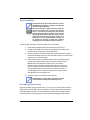
CONVENTIONS
The following icons are used throughout this document to identify additional information
of which the reader should be aware.
SHOCK HAZARD: This icon indicates the danger of
an electrical shock that may harm or otherwise prove
fatal to the user.
CAUTION: This icon indicates the existence of a
hazard that could result in equipment or property
damage or equipment failure if the safety instruction
is not observed.
ELECTROSTATIC DISCHARGE: This icon indicates
the possible presence of Electrostatic Discharge
(ESD or “static electricity”) that may harm the
internal electronic components. The user is advised
to handle the device only after discharging any
possible electrostatic buildup that may be present.
NOTE: This icon identifies information that relates to
the safe operation of the equipment or related items.
TIP: This icon identifies helpful hints and tips.
Zeus 2.5-Inch ATA Solid State Drive
iii
iv
Zeus 2.5-Inch ATA Solid State Drive
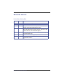
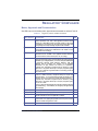
REVISION HISTORY
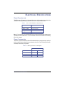
Revision Status Summary Sheet
Revision Date
Sheet(s) Affected
0.1
01/20/2007
All. Initial release. Preliminary product datasheet.
1.0
04/20/2007
Official release.
1.1
05/23/2007
Minor grammatical corrections throughout datasheet. Updated ATA
Commands and Environmental Characteristics sections.
1.2
06/11/2207
Page 7 - updated values for “Power consumption” bullets. Page 14 - updated
Table 5, “SSD Typical Power Consumption”; Page 15 - added “Start-Up Time
and Current Draw” topic and curve illustration (Figure 2).
1.3
06/18/2007
Minor spelling and grammatical corrections throughout datasheet. Page 11 removed “Erase Cycles” topic.
1.4
06/28/2007
Page 57 - removed “Firmware Upgrades” topic.
1.5
07/09/2007
All - removed any reference to “2,000,000 write/erase cycles”. Minor spelling
and grammatical corrections.
Zeus 2.5-Inch ATA Solid State Drive
v
vi
Zeus 2.5-Inch ATA Solid State Drive
TABLE OF CONTENTS
Conventions . . . . . . . . . . . . . . . . . . . . . . . . . . . . . . . . . . . . . . . . . . . . . . . . . . . . iii
Revision History. . . . . . . . . . . . . . . . . . . . . . . . . . . . . . . . . . . . . . . . . . . . . . . . . .v
List of Tables . . . . . . . . . . . . . . . . . . . . . . . . . . . . . . . . . . . . . . . . . . . . . . . . . . xiv
List of Figures . . . . . . . . . . . . . . . . . . . . . . . . . . . . . . . . . . . . . . . . . . . . . . . . . .xv
Scope . . . . . . . . . . . . . . . . . . . . . . . . . . . . . . . . . . . . . . . . . . . . . . . . . . . . . . . . . .1
Overview............................................................................................................................................ 1
Audience............................................................................................................................................ 1
Standards and Reference Documents....................................................................................... 1
Standard Features and Optional Features................................................................................. 2
Product Description.................................................................................................................... 2
Performance Characteristics...................................................................................................... 2
Electrical Specifications ............................................................................................................. 2
Interface Specifications.............................................................................................................. 2
ATA Commands......................................................................................................................... 2
Physical Characteristics............................................................................................................. 2
Environmental Characteristics ................................................................................................... 2
Installation.................................................................................................................................. 2
Regulatory Compliance.............................................................................................................. 2
Contact and Ordering Information.............................................................................................. 3
Standards and Reference Documents....................................................................................... 3
Electromagnetic Susceptibility ........................................................................................... 3
Electromagnetic Compatibility............................................................................................ 3
Military Information Systems Security Standards .............................................................. 4
Commercial Standards ...................................................................................................... 4
Reference Documents ....................................................................................................... 5
Standard Features ..................................................................................................................... 5
Interface ............................................................................................................................. 5
Performance ...................................................................................................................... 5
Zeus 2.5 ATA Solid State Drive
vii
Unformatted Capacities ..................................................................................................... 5
Reliability ........................................................................................................................... 6
Physical Characteristics..................................................................................................... 6
Environmental Characteristics ........................................................................................... 6
Compliance........................................................................................................................ 7
Power................................................................................................................................. 7
Optional Features ...................................................................................................................... 7
Optional Purge Features.................................................................................................... 8
Optional Environmental Features ...................................................................................... 8
Manufacturing............................................................................................................................ 8
Product Description . . . . . . . . . . . . . . . . . . . . . . . . . . . . . . . . . . . . . . . . . . . . . . 9
General Description................................................................................................................... 9
ATA Interface............................................................................................................................. 9
Drive Capacities ........................................................................................................................ 9
Performance .............................................................................................................................. 9
Data Security ............................................................................................................................. 9
Performance Characteristics . . . . . . . . . . . . . . . . . . . . . . . . . . . . . . . . . . . . . 10
ATA (IDE) Bus Modes ............................................................................................................. 10
Endurance ............................................................................................................................... 10
Wear-Leveling ......................................................................................................................... 10
Bad-Block Management .......................................................................................................... 10
Data Retention......................................................................................................................... 10
Error Detection and Correction................................................................................................ 11
Reliability ................................................................................................................................. 11
Error Rates ...................................................................................................................... 11
Built-In Self Test (BIST) ................................................................................................... 11
Mount Time...................................................................................................................... 11
Seek Time........................................................................................................................ 11
Data Transfer Rates ........................................................................................................ 12
Purge Times .................................................................................................................... 12
viii
Zeus 2.5 ATA Solid State Drive
Repairs............................................................................................................................. 12
Preventative Maintenance ............................................................................................... 12
Electrical Specifications . . . . . . . . . . . . . . . . . . . . . . . . . . . . . . . . . . . . . . . . . .13
Power Requirements ............................................................................................................... 13
Power Consumption................................................................................................................. 13
Start-Up Time and Current Draw ............................................................................................. 14
Activity LED.............................................................................................................................. 14
Power Savings Commands...................................................................................................... 15
Power Mode at Power On........................................................................................................ 15
Grounding ................................................................................................................................ 15
Interface Specifications. . . . . . . . . . . . . . . . . . . . . . . . . . . . . . . . . . . . . . . . . . .16
SSD Operation......................................................................................................................... 16
Primary and Secondary Modes................................................................................................ 17
I/O Primary and Secondary ATA (IDE) Modes ................................................................ 17
Addressing Modes ........................................................................................................... 17
Functional Blocks..................................................................................................................... 18
ATA (IDE) Bus Interface Block......................................................................................... 18
2.5-Inch 44-Pin ATA Bus Connector................................................................................ 18
Connector Pinout ............................................................................................................. 19
SSD Control Block ........................................................................................................... 21
ATA Commands . . . . . . . . . . . . . . . . . . . . . . . . . . . . . . . . . . . . . . . . . . . . . . . . .22
Standard ATA Commands....................................................................................................... 22
Standard ATA Command Summary ........................................................................................ 24
Check Power Mode (98h or E5h)..................................................................................... 24
Download Microcode (92h) .............................................................................................. 24
Erase Sector (C0h) .......................................................................................................... 24
Execute Drive Diagnostic (90h) ....................................................................................... 24
Flush Cache (E7h) ........................................................................................................... 24
Flush Cache Extended (EAh) .......................................................................................... 24
Format Track (50h) .......................................................................................................... 25
Zeus 2.5 ATA Solid State Drive
ix
Identify Response (ECh).................................................................................................. 25
Idle (97h, E3h) ................................................................................................................. 25
Idle Immediate (95h, E1h) ............................................................................................... 25
Initialize Drive Parameters (91h) ..................................................................................... 25
NOP (00h)........................................................................................................................ 25
Read Buffer (E4h)............................................................................................................ 25
Read DMA (C8h) ............................................................................................................. 25
Read DMA Ext (25h)........................................................................................................ 25
Read DMA Queued (C7h) ............................................................................................... 26
Read DMA Queued Ext (26h).......................................................................................... 26
Read Multiple (C4h)......................................................................................................... 26
Read Multiple Extended (29h) ......................................................................................... 26
Read Sector(s) (20h) ....................................................................................................... 26
Read Sector(s) Extended (24h) ....................................................................................... 26
Read/Verify Sector(s) (40h) ............................................................................................. 26
Read/Verify Extended (42h) ............................................................................................ 26
Recalibrate (10h) ............................................................................................................. 27
Security Disable Password (F6h) .................................................................................... 27
Security Erase Prepare (F3h) .......................................................................................... 27
Security Erase Unit (F4h) ................................................................................................ 27
Security Freeze Lock (F5h) ............................................................................................. 27
Security Set Password (F1h) ........................................................................................... 27
Security Unlock (F2h) ...................................................................................................... 27
Seek (70h, 7Fh) ............................................................................................................... 28
Set Features (EFh) .......................................................................................................... 28
Set Multiple Mode (C6h) .................................................................................................. 28
Set Sleep Mode (99h or E6h) .......................................................................................... 28
Sleep (E6h)...................................................................................................................... 28
SMART (B0h) .................................................................................................................. 28
Standby (96h or E2h)....................................................................................................... 28
Standby Immediate (94h or E0h)..................................................................................... 29
Write Buffer (E8h) ............................................................................................................ 29
x
Zeus 2.5 ATA Solid State Drive
Write DMA (CAh) ............................................................................................................. 29
Write DMA Ext (35h) ........................................................................................................ 29
Write DMA Queued (CCh) ............................................................................................... 29
Write DMA Queued Ext (38h) .......................................................................................... 29
Write Multiple (C5h) ......................................................................................................... 29
Write Multiple Ext (39h).................................................................................................... 29
Write Sector(s) (30h)........................................................................................................ 30
Write Sector(s) Ext (34h) ................................................................................................. 30
SMART Support....................................................................................................................... 30
Identify Device Information ...................................................................................................... 30
Vendor-Specific ATA Commands ............................................................................................ 40
Sanitize Erase/Fill .................................................................................................................... 40
Sanitization Standards ............................................................................................................. 41
Physical Characteristics . . . . . . . . . . . . . . . . . . . . . . . . . . . . . . . . . . . . . . . . . .42
General Physical Characteristics ............................................................................................. 42
Materials .................................................................................................................................. 42
Drive Assembly Weight............................................................................................................ 42
Storage Capacities........................................................................................................... 42
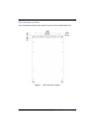
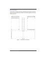
Exterior Dimensions......................................................................................................... 43
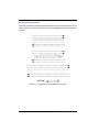
ATA Connector Location.................................................................................................. 44
Environmental Characteristics . . . . . . . . . . . . . . . . . . . . . . . . . . . . . . . . . . . . .45
Overview .................................................................................................................................. 45
Operating Temperatures.......................................................................................................... 45
Operating Requirements.......................................................................................................... 45
Non-Operating Requirements.................................................................................................. 46
Relative Humidity ..................................................................................................................... 46
Altitude Parameters ................................................................................................................. 46
Restriction of Hazardous Materials .......................................................................................... 47
Shock and Vibration................................................................................................................. 47
Failure Criteria ................................................................................................................. 47
Zeus 2.5 ATA Solid State Drive
xi
Random Vibration ............................................................................................................ 47
Shock............................................................................................................................... 47
Drop Testing .................................................................................................................... 48
Conformal Coating........................................................................................................... 48
Installation . . . . . . . . . . . . . . . . . . . . . . . . . . . . . . . . . . . . . . . . . . . . . . . . . . . . 49
System Requirements ............................................................................................................. 49
Drive Configuration.................................................................................................................. 50
Jumper Pins............................................................................................................................. 50
Drive Orientation...................................................................................................................... 51
Cooling Requirements ............................................................................................................. 52
Installation Dimensions............................................................................................................ 53
Mounting Hole Locations ......................................................................................................... 54
Drive Installation ...................................................................................................................... 55
Grounding Requirements ........................................................................................................ 55
Operating System Specifications............................................................................................. 56
Microsoft OS Compatibility .............................................................................................. 56
Non-Microsoft OS Compatibility....................................................................................... 56
System POST, Boot and Resume Times ........................................................................ 56
NAND Flash Support ............................................................................................................... 56
Diagnostic Software................................................................................................................. 56
Regulatory Compliance . . . . . . . . . . . . . . . . . . . . . . . . . . . . . . . . . . . . . . . . . . 57
Marks, Approvals and Documentation..................................................................................... 57
CB Certificate and CB Report.................................................................................................. 58
Declaration of Conformity ........................................................................................................ 58
Radio Frequency Emissions.................................................................................................... 58
Radio Frequency Immunity Requirements .............................................................................. 59
EMI Test Site Correlation......................................................................................................... 59
Verification Samples................................................................................................................ 59
Verification Testing .................................................................................................................. 59
xii
Zeus 2.5 ATA Solid State Drive
Electrostatic Discharge (ESD) ................................................................................................. 60
Acceptance Criteria Definitions................................................................................................ 60
Contact and Ordering Information . . . . . . . . . . . . . . . . . . . . . . . . . . . . . . . . . .61
Contact Information.................................................................................................................. 61
Ordering Information................................................................................................................ 61
Acronyms and Abbreviations . . . . . . . . . . . . . . . . . . . . . . . . . . . . . . . . . . . . . .63
Index . . . . . . . . . . . . . . . . . . . . . . . . . . . . . . . . . . . . . . . . . . . . . . . . . . . . . . . . . .67
Certification and Warranty . . . . . . . . . . . . . . . . . . . . . . . . . . Inside Back Cover
Zeus 2.5 ATA Solid State Drive
xiii
LIST OF TABLES
1. Error Limits ................................................................................................................... 11
2. Data Transfer Rates ..................................................................................................... 12
3. Purge Times ................................................................................................................. 12
4. Zeus 2.5-Inch SSD Power Requirements..................................................................... 13
5. SSD Typical Power Consumption ................................................................................ 13
6. ATA (IDE) Bus Addressing Modes ............................................................................... 17
7. ATA Connector Pinout Configuration ........................................................................... 19
8. Supported ATA Commands.......................................................................................... 22
9. SSD Identify Device Information................................................................................... 31
10. Sanitize Standards Compliance ................................................................................... 41
11. Zeus ATA SSD Capacities ........................................................................................... 42
12. 2.5 Drive Assembly Dimensions................................................................................... 43
13. Operating Temperatures .............................................................................................. 45
14. Operating Requirements .............................................................................................. 45
15. Non-Operating Requirements....................................................................................... 46
16. Relative Humidity Criteria ............................................................................................. 46
17. Operating and Non-Operating Altitudes ....................................................................... 46
18. Random Vibration Levels ............................................................................................. 47
19. Shock Test Results....................................................................................................... 47
20. ATA (IDE) Cable Requirements ................................................................................... 49
21. Regulatory Marks and Documentation ......................................................................... 57
22. EMI Specification Limits ............................................................................................... 58
23. ESD Requirements....................................................................................................... 60
24. Acceptance Criteria Definitions .................................................................................... 60
xiv
Zeus 2.5-Inch ATA Solid State Drive
LIST OF FIGURES
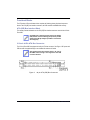
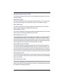
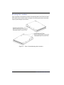
1. The Zeus 2.5-Inch ATA Solid State Drive............................................................................... 1
2. Start-Up Current Draw .......................................................................................................... 14
3. 44-pin ATA (IDE) Bus Connector.......................................................................................... 18
4. Zeus 2.5-inch ATA SDD Exterior Dimensions ...................................................................... 43
5. ATA Connector Location....................................................................................................... 44
6. Primary/Secondary Setting for 2.5-inch Zeus ATA SSDs..................................................... 50
7. Possible Drive Orientations .................................................................................................. 51
8. Suggested Air Flow Patterns for Cooling.............................................................................. 52
9. Exterior Mounting Specifications .......................................................................................... 53
10. Zeus 2.5-Inch Mounting Hole Locations ............................................................................... 54
Zeus 2.5-Inch ATA Solid State Drive
xv
xvi
Zeus 2.5-Inch ATA Solid State Drive
SCOPE
Figure 1.
The Zeus 2.5-Inch ATA Solid State Drive
OVERVIEW
This datasheet describes the applications, specifications, and installation of the 2.5-inch Zeus ATA
Solid State Drive (SSD). The contents of this datasheet can be quickly ascertained by reviewing the
abstracts described under the Scope section.
AUDIENCE
This datasheet is intended for system engineers or system designers employed by an Original
Equipment Manufacturer (OEM). This datasheet was therefore written specifically for a technically
advanced audience; it is not intended for end-users that will eventually purchase the commercially
available product. The user, as referenced throughout this document, is primarily concerned with
industrial, commercial, or military applications.
Standards and Reference Documents
This section discusses the formal standards that may apply to the Zeus 2.5-Inch ATA SSD, including
electrical product standards and military information security standards. In addition, this section lists
reference documents relevant to the ATA protocols used for the Zeus ATA SSD.
Zeus 2.5-Inch ATA Solid State Drive
1
Standard Features and Optional Features
These two sections list the standard and optional features of the Zeus 2.5-Inch ATA SSD.
Product Description
This section provides a general description of the Zeus 2.5-Inch ATA SSD, and includes media,
performance, reliability and capacity information.
Performance Characteristics
This section describes the internal and seek characteristics of the Zeus ATA SSD and includes
information on the access execution times.
Electrical Specifications
This section describes the power requirements and power consumption parameters of the Zeus ATA
SSD and includes explanations of power-saving commands supported by the drive.
Interface Specifications
This section provides a table of the connector pinout and tables of the electrical characteristics for
the pin signals. In addition, this section describes how the drive uses the pin signals when interacting
with the host system.
ATA Commands
This section provides a table of the ATA commands supported by the Zeus 2.5-Inch ATA SSD,
followed by a subtopic discussing the use of each command.
Physical Characteristics
This section describes the overall physical dimensions of the SSD, the materials used in its
construction, and the average weight of the assembly.
Environmental Characteristics
The general operating and non-operating conditions for the Zeus SSD are detailed in this section.
This section includes operating temperatures, relative humidity, altitude, and shock, drop and
vibration testing results.
Installation
This section discusses issues relating to the installation of the Zeus 2.5-Inch ATA SSD in a PC or
alternate enclosure, including cooling and grounding.
Regulatory Compliance
This section provides and overview of the marking, approval, documentation and reporting
conventions for the Zeus 2.5-Inch ATA SSD.
2
Zeus 2.5-Inch ATA Solid State Drive
Contact and Ordering Information
Please consult this section if you need to contact the Solid State Drive Team. The Ordering
Information table allows you to decode the part number found on your model of Zeus drive.
Standards and Reference Documents
This section discusses the various standards for electronic products and military use, and how those
standards apply to the Zeus 2.5-Inch ATA SSD.
Electromagnetic Susceptibility
The Zeus 2.5-inch ATA SSD is intended for installation by the user in an appropriate enclosure, i.e.,
a PC or alternate enclosure. The enclosure must be designed so that the use of the Zeus drive does
not impair nearby electronic equipment within the same enclosure and external to the enclosure.
The user, as previously defined under the Audience section, is responsible for choosing designing
and testing the enclosure so that it is appropriate as previously defined, and complies to related
regulations, such as Subpart B of Part 125 of FCC Rules and Regulations, and Radio Interference
Regulations of the Canadian Department of Communications.
Electromagnetic Compatibility
Independent laboratories are in the process of confirming that the Zeus 2.5-inch ATA SSD meets the
requirements for CE Marking. While the drive may have CE Marking, the OEM must confirm CE
Marking for the product in which the drive has been integrated. Test systems confirming the CE
Marking may include the following:
•
A current microprocessor
•
Floppy diskette drive
•
Keyboard
•
Monitor
•
Printer
•
External modem
•
Mouse
Zeus 2.5-Inch ATA Solid State Drive
3
Military Information Systems Security Standards
The Zeus 2.5-inch ATA SSD complies in whole or part with the following Military Information Systems
security standards:
•
DoD 5220.22-M
•
MIL-STD-810F
•
NSA 130-2
•
AR 380-19
•
AFSSI 5020
•
Navso-P5239
•
NEBS Level 3
Commercial Standards
Zeus SSDs comply, in whole or in part, with the following commercial standards:
4
•
S/NZS 3548 Class B
•
BSMI CNS 13438 Class B
•
CAN/CAS-V3/2001.04 (VCCI)
•
CE (Conformite Europenne)
•
CISPR 22 Class B
•
EN 55022 Class B
•
EN 61000-3-2
•
EN 61000-3-3
•
FCC Part 15 Class B
•
Underwriters Laboratories (UL)
•
NEBS Level 3
•
IEC 61000-4-2
•
IEC 61000-4-3
•
IEC 61000-4-4
•
IEC 61000-4-5
•
IEC 61000-4-6
•
IEC 61000-4-8
•
IEC 61000-4-11
Zeus 2.5-Inch ATA Solid State Drive
Reference Documents
The following list of ANSI documents are relevant to the Zeus 2.5-inch ATA SSD:
•
ANSI-INCITS 361-ATA-6
•
ANSI-INCITS 340-ATA-5
•
ANSI-INCITS 317-ATA-4
•
ANSI-X3.298-1997-ATA-3
•
ANSI-X3.279-1996-ATA-2
Standard Features
Interface
• Conforms to ATA-6 Specification Standard
• 16-bit interface
• Primary/Secondary jumper
• Low-level format at factory; shipped with NTFS format
• No special drivers required
Performance
• Fast initialization
• Supports PIO Modes 0 - 4
• Supports Ultra DMA Modes 0 - 5
• Burst Read/Write performance up to 66 MB/sec
• Sustained Read/Write up to 40 MB/sec
Unformatted Capacities
• 8, 16, 32 and 64 gigabytes
• Endurance
• Supports unlimited Read cycles
• Wear-leveling algorithms
• Bad-block mapping algorithms
Zeus 2.5-Inch ATA Solid State Drive
5
Reliability
• Solid state design
• Data integrity: 10-year data retention
• Manual and automatic self-diagnostic tests
• Embedded EDC/ECC (Error Detection and Error Correction)
• Dependable operation under unstable power conditions
• Rugged, impact-resistant casing
• 5 year warranty
Physical Characteristics
• Larger capacities available as custom design
• Industry-standard 2.5-inch HDD form factor, precision
machined aluminum alloy enclosure
• Compact design: 100.2mm (L) x 69.8mm (W) x 9.5mm (H)
• Weight: < 0.4 kg
Environmental Characteristics
• Two operating temperature ranges available:
–
Commercial range: 0oC to 70oC
–
Industrial range: -40oC to 85oC
• Storage Temperature of -55oC to 95oC
• Humidity of 5% to 95% relative, non-condensing
• Operating altitude of 80,000 feet
• Operating Shock of 1,500G, MIL-STD-810F
(0.3 to 0.75ms duration, half-sine, 3 cycles per axis)
• Operating Vibration of 16.3G RMS, MIL-STD-810F
(Random, 20Hz to 2,000Hz; 1 hour duration, 3 axes)
• 0dB Noise Amplitude
6
Zeus 2.5-Inch ATA Solid State Drive
Compliance
• Meets NEBS Level 3 requirements for telco electrical environments.
• Meets U.S. Army, Navy, Air Force and DoD security erase and sanitization (purge)
guidelines.
• Meets UL 1950 requirements for Electrical Equipment sold in the United States of
America and is marked accordingly.
• Compliance with CSA CAN/CSA-C22.2, No. 950-M89 requirements for Electrical
Equipment sold in Canada and is marked accordingly.
• Compliance with European Community (European Union) Information Technology
Equipment (ITE) directives.
• MIC (Korean) certified.
• BSMI (Taiwan) certified.
• VCCI (Japan) certified.
• C-Tick (Australia) certified.
• FCC Declaration of Conformity (DoC).
Power
• Input voltage: 5V DC +/-5%
• Typical power consumption:
–
Start-Up: 333.60mA
–
Idle: 375mA
–
Read: 560mA
–
Write: 545mA
Optional Features
• SMART (Self-Monitoring, Analysis and Reporting Technology) status monitoring.
• Sanitization (“Sanitize Erase/Fill”)
Zeus 2.5-Inch ATA Solid State Drive
7
Optional Purge Features
• BasicPurge™: Erases solid state drive
• RapidPurge™: Erases solid state drive in seconds
• MilPurge™: Erases solid state drive in compliance with security guidelines (DoD
5220.22-M, NSA 130-2, AFSSI 5020, AR 380-19 and Navso 5239
• Intelligent Destructive Purge™: Physically damages the flash media to make data
retrieval impossible
• Hardware Purge
Optional Environmental Features
• Conformal coating
Manufacturing
• Santa Ana, California
United States of America
• ISO 9001 Certified
8
Zeus 2.5-Inch ATA Solid State Drive
PRODUCT DESCRIPTION
General Description
The Zeus 2.5-inch ATA Solid State Drive (SSD) is a non-volatile, mass storage device. The drive is
intended as a replacement for a standard IDE/ATA-compliant hard disk drive (HDD). No additional
device drivers are required, and the drive can be configured as a boot or data storage device.
ATA Interface
The SSD can be installed in any operating system environment that supports ATA-6 or greater
devices. The drive is configured with a standard 44-pin IDE/ATA interface, is fully ATA-6 compliant,
and conforms to the same mechanical and mounting requirements as standard rotating disk drives.
The drive supports Primary/Secondary (Device 0/Device 1) mode operation via a set of jumper pins.
Drive Capacities
The SSD is available in unformatted memory capacities of 8, 16, 32 and 64 gigabytes. The memory
consists of Single-Level Cell (SLC) NAND Flash components.
Performance
Zeus SSDs can operate at sustained data transfer rates of up to 40 MB per second. Power
consumption is kept to a minimum; the SSDs can be powered from a single 5-volt source. The solid
state design eliminates electromechanical noise and delay inherent in traditional magnetic rotating
media. The wear-leveling and bad-block mapping algorithms ensure consistency, accuracy, and
integrity of user data. Data reliability is achieved through embedded Error Detection and Error
Correction Code (EDC/ECC).
Data Security
Zeus SSDs offer optional user-defined data sanitization (purge) features. Supporting both sanitized
erase/fill and non-recoverable sanitization options, the SSDs can be configured to remove data from
the drive, freeing storage space for later reuse, or to remove data and destroy the storage media,
making the SSD unusable and data retrieval impossible. The data security features of the drives
comply with Department of Defense (DoD) and US military data security standards, including AFSSI
5020, AR 380-19, NAVSO P-5239-26, NISPOM DoD 5220.22-M and NSA 130-2.
Zeus 2.5-Inch ATA Solid State Drive
9
PERFORMANCE CHARACTERISTICS
ATA (IDE) Bus Modes
Zeus SSDs support the following ATA operating modes:
• PIO Modes 0 - 4
• DMA Modes 0 - 2
• Ultra DMA Modes 0 - 5
Endurance
The useful life of flash media is limited by the number of write/erase operations that can be performed
on the media. To extend the useful life of the SSD, special wear-leveling and bad-block mapping
algorithms are integrated in the firmware.
Wear-Leveling
The dynamic wear-leveling algorithm integrated in the firmware guarantees that erase/write cycles
are evenly distributed across all of the flash memory block locations. Wear-leveling eliminates
repeated writes to the same physical flash memory location, thereby preventing blocks from
premature wear.
Bad-Block Management
The bad-block mapping algorithm replaces bad blocks with new ones from available spares. Two
percent (2%) of the flash memory is held in reserve (spare block) for bad block replacement. Bad
blocks in the media are flagged when detected. The next time an attempt is made to access a flagged
block, it is immediately replaced by a spare block. The bad block mapping function enables data to
be automatically transferred from a bad sector to an available spare block.
Notes:
1
STEC Inc. scans for bad blocks during the manufacturing process at the initial installation
of the flash components. Bad blocks are mapped and identified during the manufacturing
process.
2
The maximum amount of available user space will not be less than 97% of the total flash
capacity, i.e., the reserved space will not exceed more than 3% of the total drive volume
Data Retention
Data stored on a Zeus SSD will remain valid for ten (10) years without requiring power support. The
unit can be stored under certain environmental conditions for extended periods without any
occurrence of data degradation.
10
Zeus 2.5-Inch ATA Solid State Drive
Error Detection and Correction
The Error Detection Code and Error Correcting Code (EDC/ECC) helps maintain data integrity by
allowing single or multiple bit corrections to the data stored in the flash array. If the data in the flash
array is corrupted due to aging or during the programming process, the EDC/ECC will compensate
for the errors to ensure the delivery of accurate data to the host computer. The EDC/ECC engine is
capable of correcting up to 4 bytes in error and detecting up to 5 bytes in error. An extensive retry
algorithm is also implemented on all Zeus SSDs, so that single event disturbances such as ESD or
EMF occurring during a read operation can be readily overcome.
Reliability
• DC power is maintained as specified in the datasheet
• Errors caused by the host are excluded from rates
• Errors from the same causes are counted as 1 block
• Data stream is assumed random
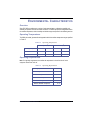
Error Rates
Table 1 lists the error limit specifications. When all data correction mechanisms are enabled, the error
rate will be sustained through all operating temperature ranges as specified in the previous sections.
Table 1.
Error Type
Error Limits
Maximum Number of Errors
Recoverable Data Error
1 bit in 1020
Unrecoverable Data Error
Less than 1 bit in 1020
Built-In Self Test (BIST)
During power-up, the micro-controller tests the controller memory, and then performs a back-end
status check to verify proper flash memory controller operations. If a fault condition is detected in the
flash memory controller, the SSD’s status is reported as failed.
Mount Time
The amount of time required to initialize and mount a Zeus SSD varies according to the operating
system (Windows®, Linux®, etc.) in which the SSD is running and the storage capacity of the drive.
Seek Time
Unlike a magnetic rotating disk, the SSD has no read/write heads or platters. There is no seek time
or rotational latency issues. The SSDs dramatically improve transaction throughput, particularly for
applications that are configured to take advantage of the characteristics of the drive.
Zeus 2.5-Inch ATA Solid State Drive
11
Data Transfer Rates
The data transfer rate varies according to the flash controller/flash memory configuration of the drive.
The scalable architecture of the drive is capable of accommodating sustained and burst data transfer
rates as listed in Table 2.
Table 2.
Data Transfer Rates
Parameter
Value
Units
Average Access
0.3
m/sec
Average Latency
0.3
m/sec
Sustained Read
40
Megabytes/sec
Sustained Write
26
Megabytes/sec
Burst Read
66
Megabytes/sec
Burst Write
66
Megabytes/sec
Purge Times
The time required to purge a Zeus SSD depends on the actual purge option invoked by the user and
the flash controller/flash memory configuration of the drive. A list of representative purge times is
listed in Table 3, with the value expressed in seconds per 32 Gigabytes (sec/32GB) for each purge
option.
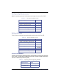
Table 3.
Purge Times
Purge Option
Value
Units
BasicPurge
360
sec/32GB
RapidPurge
9
sec/32GB
1,200
sec/32GB
2
sec/32GB
MilPurge
Intelligent Destructive Purge
Repairs
A defective SSD should be replaced. There are no parts, assemblies or subassemblies that can be
repaired individually by the user. Please see the section titled Certification and Warranty on the
inside of the back cover page. Unauthorized repairs to the SSD will void the warranty.
Preventative Maintenance
No preventative maintenance is required. The SSD unit is sealed at the factory, and there are no
parts, assemblies, or subassemblies that require preventative maintenance on behalf of the user.
Please see the section titled Certification and Warranty on the inside of the back cover page.
Unauthorized maintenance to the SSD will void the warranty.
12
Zeus 2.5-Inch ATA Solid State Drive
ELECTRICAL SPECIFICATIONS
Power Requirements
The SSD requires a 5V power source. If a power failure occurs, the drive design ensures that the data
contained in the storage memory is preserved. Data loss or corruption does not occur.
Table 4.
Zeus 2.5-Inch SSD Power Requirements
Item
Requirement
Input Voltage1
5V +/-5% (4.75V Min, 5.25V Max)
Ripple (0-30MHz)
70 mV p-p (for 3.3V)
Supply Rise Time
7 - 100 ms
Supply Fall Time
< 5s
Note: (1) The voltage rail, which includes ripples, does not exceed or fall below the voltage range as
specified by the Min and Max values, i.e., the Min and Max numbers are the absolute floor and ceiling
for the input voltages.
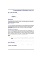
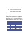
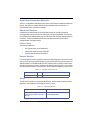
Power Consumption
The amount of power consumed by a Zeus SSD is determined by the storage (memory) capacity of
the drive, and the flash controller/memory configuration of the drive. Table 5 lists the typical power
consumption of the drives per operation.
Table 5. SSD Typical Power Consumption
Power Consumption
Operation
Typical
Maximum
Idle
375mA
425mA
Read (40MB/sec)
400mA
560mA
Write (26MB/sec)
400mA
545mA
Zeus 2.5-Inch ATA Solid State Drive
13
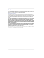
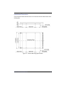
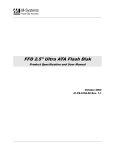
Start-Up Time and Current Draw
The Start-Up current was measured during the power-on phase of the computer and drive. The StartUp time was ~850ms. Figure 2 shows the current draw during start-up, with an average current of
333.5mA RMS.
Figure 2. Start-Up Current Draw
Activity LED
Zeus SSDs are configured to drive Pin 39 (-DASP; Disk Present/Secondary Active) of the ATA cable
during all command activity and during periods when the drive indicates a busy state. (Example: Offline diagnostic activities.)
14
Zeus 2.5-Inch ATA Solid State Drive
Power Savings Commands
Zeus SSDs support the following Power Savings commands and respond with the appropriate status:
•
•
•
•
•
Check Power Mode
Idle
Standby
Standby Immediate
Sleep
The drives comply with all specifications that define the behavior of storage devices as it relates to
power management and advanced power management (APM). When the SSDs receive a power
management command, all data in the Write cache buffer is written to the media before Drive Ready
is asserted.
Power Mode at Power On
The drives comply with the ATA-6 Power Management Specification. During the Power On Reset
sequence, the drive functions properly and responds as appropriate. In addition, if a SRST (ATA
Interface Reset) occurs during this sequence, the drives still respond normally. After power on or hard
reset, the drive goes into IDLE or STANDBY mode, depending on the setting by the host.
Grounding
Signal and chassis grounds are connected together in the drive. To ensure minimal EM emissions,
the user should provide maximum surface contact area when connecting the drive to the chassis
ground.
Zeus 2.5-Inch ATA Solid State Drive
15
INTERFACE SPECIFICATIONS
SSD Operation
The Zeus SSD comprises three primary functional blocks: the ATA (IDE) interface connector, Zeus
SSD controller and NAND flash memory. A description of each drive component appears under
Functional Blocks.
Read/write data transfer requests are initiated by the host via the ATA (IDE) bus interface. Once
received, the Zeus controller, under the direction of the microcontroller, processes the request.
The microcontroller is responsible for initiating and controlling all
activity within the Zeus controller, including bad-block mapping
and executing the wear-leveling algorithms.
The Zeus controller decodes an incoming host command, and
configures the appropriate interrupts and status for the local
microprocessor to handle various ATA commands. For read and
write transfer commands, the hardware can handle the initial
handshake with the host automatically. If firmware enables full
auto mode, read and write transfers can be fully handled by
hardware with minimum firmware support.
Commands that do not require data to be read from or written to the flash memory controller are
typically handled by the Zeus controller. Some commands may require the Zeus controller to use
external circuitry (for example, Intelligent Destructive Purge™), that do not involve the flash memory
controller.
When a write operation is requested and data is received, the controller uses integrated DMA
controllers to transfer the data from host memory to the flash memory controller. Through a standard
ATA (IDE) interface, the flash memory controller transfers the data from the Zeus controller to
available locations in the local flash memory of the SSD. Zeus SSD storage capacity can range
between from 8GB to 64GB, with internal IDE transfer rates of 26 MB per second. The Zeus controller
notifies the host after the write operation is completed.
If a read request is received, the Zeus controller retrieves the data from the local flash memory via
the flash memory controller. If the Zeus controller is responding to a PIO read operation, it presents
the data to the ATA bus. If it is responding to a UDMA read request, the Zeus controller writes the
data directly to system memory on the host. Regardless of the type of operation (PIO or UDMA), the
Zeus controller notifies the host when the data is ready for transmission.
16
Zeus 2.5-Inch ATA Solid State Drive
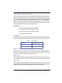
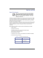
Primary and Secondary Modes
The Zeus SSD is configured as a high-performance I/O device and supports Primary (Device 0) and
Secondary (Device 1) modes:
Device Mode
Primary
Secondary
Description
Drive address at system ATA I/O address 1F0h - 1F7h and 3F6h - 3F7h. The
host must provide chip-enable #CS0 and #CS1. The SSD decodes addresses
DA0 - DA2.
Drive address at system ATA I/O address 170h - 177h and 376h - 377h. The
host must provide chip-enable #CS0 and #CS1. The SSD decodes addresses
DA0 - DA2.
I/O Primary and Secondary ATA (IDE) Modes
Primary and secondary drive addressing modes allow hosts to use the ATA-standard’s reserved disk
drive I/O addresses. This provides system designers with the simplest way to accommodate ATAprotocol devices.
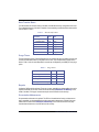
Addressing Modes
Zeus SSDs, on a command-by-command basis, can operate in either CHS or LBA addressing
modes. Identify Drive Information (See Identify Drive Information on page 26.) signals the host
whether the drive supports LBA mode. The host selects LBA mode via the Drive/Head register.
Sector Number, Cylinder Low, Cylinder High, and Drive/Head register bits HS3=0 contain the zerobased LBA. The sectors are linearly mapped with: LBA = 0 => Cylinder 0, Head 0, Sector 1.
Regardless of the translation mode, a sector LBA address does not change. LBA = (Cylinder * No of
Heads + Head) * (Sectors/Track) + (Sector - 1). Table 6 lists the supported IDE addressing modes.
Table 6.
ATA (IDE) Bus Addressing Modes
#CS0
#CS1
DA2
DA1
DA0
1
1
1
0
1
1
0
0
0
0
0
0
0
0
1
0
0
0
0
0
1
1
1
1
1
1
1
1
X
0
1
X
1
1
0
0
0
0
1
1
1
1
X
X
0
X
1
1
0
0
1
1
0
0
1
1
X
X
X
X
0
1
0
1
0
1
0
1
0
1
Zeus 2.5-Inch ATA Solid State Drive
#IORD - “0”
Hi-Z
Hi-Z
Hi-Z
Invalid
Alternate Status
Device Address
Data
Error
Sector Count
Sector Number
Cylinder Low
Cylinder High
Drive/Head
Status
#IOWR - “0”
Not Used
Not Used
Not Used
Invalid
Device Control
Not Used
Data
Feature
Sector Count
Sector Number
Cylinder Low
Cylinder High
Drive/Head
Command
17
Functional Blocks
The ATA series of Zeus solid state drives comprise the following primary functional component
blocks: The ATA (IDE) bus interface connector, the SSD controller and NAND flash memory.
ATA (IDE) Bus Interface Block
This section provides information on the ATA (IDE) Bus interface connector used with the 2.5-inch
Zeus SSD.
Zeus SSDs have a plastic key to block pin 20 on the ATA bus
(IDE) interface connector. Blocking pin 20 prevents possible
damage to the SSD by making it impossible to connect to the
drive improperly.
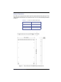
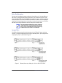
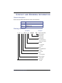
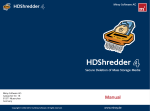
2.5-Inch 44-Pin ATA Bus Connector
The 2.5-inch Zeus SSD is equipped with a 44-pin ATA bus connector. See Figure 3. DC power and
IDE bus traffic is supplied through a non-shielded 44-conductor I/O cable.
ATA standards require 80-conductor cables to be used for
Ultra DMA modes 3 through 5. The length of the cable shall
not exceed 18 inches.
Figure 3.
18
44-pin ATA (IDE) Bus Connector
Zeus 2.5-Inch ATA Solid State Drive
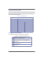
Connector Pinout
Table 7 provides the signal assignment for each pin on the ATA (IDE) bus connector. The table
applies to the 44-pin ATA bus/DC power combination connector used on 2.5-inch drives.
Table 7.
ATA Connector Pinout Configuration
Pin
Pin Type
Signal Symbol
Signal Name
Signal Description
1
1
-RESET
HOST RESET
Reset signal from host. Reset is active on power
up and inactive thereafter.
2
Ground
GND
-
Ground
3
I/O
D07
HOST DATA 07
4
I/O
D08
HOST DATA 08
5
I/O
D06
HOST DATA 06
Pins 3 through 18 (16 lines (15-0) carry the data
between the controller and the host. The low 8
lines transfer commands and the ECC
information between the host and the controller.
6
I/O
D09
HOST DATA 09
7
I/O
D05
HOST DATA 05
8
I/O
D10
HOST DATA 10
9
I/O
D04
HOST DATA 04
10
I/O
D11
HOST DATA 11
11
I/O
D03
HOST DATA 03
12
I/O
D12
HOST DATA 12
13
I/O
D02
HOST DATA 02
14
I/O
D13
HOST DATA 13
15
I/O
D01
HOST DATA 01
16
I/O
D14
HOST DATA 14
17
I/O
D00
HOST DATA 00
18
I/O
D15
HOST DATA 15
19
Ground
GND
-
Ground
20
-
-
-
No connection. Reserved for connector key.
21
O
DREQ
DMA REQUEST
Not used.
22
Ground
GND
-
Ground
23
I
-IOWR
I/O WRITE
This I/O Write strobe pulse is used to clock I/O
data or commands on the drive data bus into the
drive controller registers when the drive is
configured to use the I/O interface. The clocking
will occur on the negative to positive edge of the
signal (trailing edge.
24
Ground
GND
-
Ground
25
I
-IORD
I/O READ
This is a Read strobe generated by the host. The
signal gates I/O data or status on the host bus
and strobes the data from the controller into the
host on the low to high transition (trailing edge).
26
Ground
GND
-
Ground
27
I
IORDY
I/O READY
Not used. Pulled up to Vcc through a 4.7k ohm
resistor.
Zeus 2.5-Inch ATA Solid State Drive
19
20
Pin
Pin Type
Signal Symbol
Signal Name
Signal Description
28
I
-CSEL
CABLE SELECT
This internally pulled up signal is used to
configure the drives as the Primary or the
Secondary device. When the pin is grounded,
the device is configured as the Primary device.
When the pin is open, the device is configured as
a Secondary device.
29
I
-DACK
DMA ACKNOWLEDGE
Not used.
30
Ground
GND
-
Ground
31
O
INTRQ
INTERRUPT REQUEST
This is an interrupt request from the controller to
the host, asking for service. This signal is the
active high Interrupt Request to the host.
32
O
-IOS16
I/O SELECT 16
Not used.
33
I
A1
HOST ADDRESS 1
The address line A1 is used to select one of eight
registers in the controller Task File.
34
I/O
-PDIAG
35
I
A0
HOST ADDRESS 0
36
I
A2
HOST ADDRESS 2
37
I
-CS1
HOST CHIP SELECT 1
The chip select signal used to select the Task
File register.
38
I
-CS2
HOST CHIP SELECT 2
The chip select signal used to select the
Alternate Status register and the Device Control
register.
39
I/O
-DASP
DISK ACTIVE/
This input/output is the Disk Active/Secondary
SECONDARY PRESENT Present signal in the Primary/Secondary
handshake protocol.
40
Ground
GND
-
Ground
41
-
VCC
Supply Voltage
5V Power Supply
42
-
VCC
Supply Voltage
5V Power Supply
43
Ground
GND
-
Ground
44
-
-
-
No Connection
After an Executive diagnostic command to
indicate that the Primary device has passed its
diagnostics, this bi-directional open drain signal
is asserted by the Secondary device.
The address lines A0 and A2 are used to select
one of eight registers in the controller Task File.
Zeus 2.5-Inch ATA Solid State Drive
SSD Control Block
The control block of the Zeus SSD is comprised of three integrated components:
• FPGA Controller
• RISC Microcontroller
• NAND SLC Flash Memory
FPGA Controller
The Field Programmable Gate Array (FPGA) controller Zeus SSD provides the ATA interface to the
host, and the IDE interface to the local flash memory installed in the drive. The integrated DMA
controller interfaces with system memory to facilitate data transfer between the host and the local
flash memory in the SSD.
RISC Microcontroller
An integrated RISC microcontroller is responsible for initiating and controlling all activity within the
Zeus ATA controller. The microcontroller features more than 1 Mbit of on-chip SRAM and a wide
range of peripheral functions, with 8 Mbits of flash memory into a single compact 120-BGA package.
The embedded microcontroller is a high-performance processor with a high-density instruction set
with very low power consumption. In addition, a large number of internally banked registers provide
very fast exception handling, making it ideal for real-time application control requirements. The 8level priority-vectored interrupt controller, together with the Peripheral Data Controller, significantly
enhance the real-time performance of the SSD.
The flash memory controller architecture requires only minimal external component support. The
flash controller can interface with a wide range of compatible flash memory devices from other
manufacturers. Features of the flash memory controller include:
• Built-in 3.3V voltage regulator for flash memory supply
• Data transfer rates up to 40 MB/sec (controller to flash memory)
• True-IDE mode support
• Embedded ECC unit
• Wear-leveling and bad-block mapping software
NAND SLC Flash Memory
The local storage subsystem uses Single-Level Cell (SLC) NAND, non-volatile flash memory that has
only two states and one bit of stored data. The SLC NAND flash control logic on the SSD is able to
conserve energy when managing the electrical charge during operations.
Zeus 2.5-Inch ATA Solid State Drive
21
ATA COMMANDS
This section provides information on the ATA commands supported by the Zeus SSD. The
commands are issued to the ATA by loading the required registers in the command block with the
supplied parameter, and then writing the command code to the register.
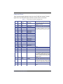
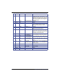
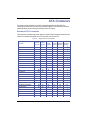
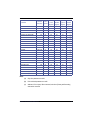
Standard ATA Commands
Table 8 lists each command along with its respective command code and registers accessed by the
command. For detailed descriptions of the ATA commands, refer to the ATA-6
Table 8.
Command
Supported ATA Commands
Command Feature
Code (Hex) Register
Sector
Count
Register
Sector Cylinder Drive/Head
Number High/Low Number
Register Register Register
98h or E5h
No
Yes
No
No
Yes(a)
DOWNLOAD MICROCODE
92h
Yes
No
No
No
No
ERASE SECTOR
C0h
No
Yes
Yes
Yes
Yes(a)
CHECK POWER MODE
EXECUTE DRIVE DIAGNOSTIC
90h
No
No
No
No
Yes(a)
FLUSH CACHE
E7h
TBD
TBD
TBD
TBD
TBD
FLUSH CACHE EXTENDED
EAh
TBD
TBD
TBD
TBD
TBD
FORMAT TRACK
50h
No
Yes
No
Yes
Yes(b)
IDENTIFY RESPONSE
ECh
Yes
No
No
No
Yes(a)
IDLE
97h, E3h
No
Y
No
No
Yes(a)
IDLE IMMEDIATE
95h, E1h
No
No
No
No
Yes(a)
INITIALIZE DRIVE PARAMETERS
91h
No
Yes
No
No
Yes(b)
NOP
00h
No
No
No
No
Yes(b)
READ BUFFER
E4h
No
No
No
No
No
READ DMA
C8h
No
Yes
Yes
Yes
Yes(b)
READ DMA EXTENDED
25h
No
Yes
Yes
Yes
Yes(b)
READ DMA QUEUED
C7h
No
Yes
Yes
Yes
Yes(b)
READ DMA QUEUED EXT
26h
No
Yes
Yes
Yes
Yes(b)
READ MULTIPLE
C4h
No
Yes
Yes
Yes
Yes(b)
READ MULTIPLE EXTENDED
29h
No
Yes
Yes
Yes
Yes(b)
READ SECTOR(S)
20h
No
Yes
Yes
Yes
Yes(b)
READ SECTOR(S) EXTENDED
24h
No
Yes
Yes
Yes
Yes(b)
READ VERIFY SECTOR(S)
40h
No
Yes
Yes
Yes
Yes(b)
READ VERIFY EXTENDED
42h
No
Yes
Yes
Yes
Yes(b)
RECALIBRATE
10h
No
No
No
No
Yes(a)
22
Zeus 2.5-Inch ATA Solid State Drive
Command Feature
Code (Hex) Register
Command
Sector
Count
Register
Sector Cylinder Drive/Head
Number High/Low Number
Register Register Register
SECURITY DISABLE PASSWORD
F6h
No
No
No
No
Yes(a)
SECURITY ERASE PREPARE
F3h
No
No
No
No
Yes(a)
SECURITY ERASE UNIT
F4h
No
No
No
No
Yes(a)
SECURITY FREEZE LOCK
F5h
No
No
No
No
Yes(a)
SECURITY SET PASSWORD
F1h
No
No
No
No
Yes(a)
SECURITY UNLOCK
F2h
No
No
No
No
Yes(a)
70h - 7Fh
No
No
Yes
Yes
Yes(b)
SET FEATURES
EFh
No
Yes
Yes
Yes
Yes(b)
SET MULTIPLE MODE
C6h
No
Yes
No
No
Yes(a)
SLEEP
E6h
No
No
No
No
Yes(a)
SMART
B0h
Yes
Yes
Yes
Yes
Yes(b)
STANDBY
96h or E2h
No
Yes
No
No
Yes(a)
STANDBY IMMEDIATE
94h or E0h
No
No
No
No
Yes(a)
WRITE BUFFER
E8h
No
Yes
Yes
Yes
Yes(b)
WRITE DMA
CAh
No
Yes
Yes
Yes
Yes(b)
WRITE DMA EXTENDED
35h
No
Yes
Yes
Yes
Yes(b)
WRITE DMA QUEUED
CCh
No
Yes
Yes
Yes
Yes(b)
WRITE DMA QUEUED EXT
36h
No
Yes
Yes
Yes
Yes(b)
WRITE MULTIPLE
C5h
No
Yes
Yes
Yes
Yes(b)
WRITE MULTIPLE EXTENDED
39h
No
Yes
Yes
Yes
Yes(b)
WRITE MULTIPLE FUA EXT
CEh
No
Yes
Yes
Yes
Yes(b)
WRITE SECTOR(S)
30h
No
Yes
Yes
Yes
Yes(b)
WRITE SECTOR(S) EXTENDED
34h
No
Yes
Yes
Yes
Yes(b)
SEEK
Notes:
(a)
Only drive parameters are valid.
(b)
Drive and head parameters are valid.
(c)
Address to Drive 0 (zero). When executed, both drives (Primary and Secondary)
execute this command.
Zeus 2.5-Inch ATA Solid State Drive
23
Standard ATA Command Summary
This section provides a summary of each supported ATA command.
Check Power Mode (98h or E5h)
The Check Power Mode command allows the host to determine the current power mode of the
device. The Check Power Mode command shall not cause the device to change power or affect the
operation of the Standby timer.
Download Microcode (92h)
The command allows the host to alter the microcode of the device. The data transferred using the
Download Microcode command is vendor-specific. All transfers are an integer multiple of the sector
size. The size of the data transfer is determined by the contents of the LBA Low register and the
Sector Count register. The LBA Low register will extend the Sector Count register to create a 16-bit
sector count value. The LBA Low register will be the most significant eight bits and the Sector Count
register will be the least significant eight bits. A value of zero in the LBA Low and Sector Count
registers specify that no data is to be transferred. This allows transfer sizes from 0 bytes to
33,553,920 bytes, in 512-byte increments. The Features register will determine the effect of the
Download Microcode command.
Erase Sector (C0h)
This command will pre-erase and condition the data sectors in advance.
Execute Drive Diagnostic (90h)
This command performs the internal diagnostic tests implemented by the controller.
Flush Cache (E7h)
This command is used by the host to request the device to flush the Write cache. If there is data in
the Write cache, that data shall be written to the media. The command will not indicate completion
until the data is flushed to the media or an error occurs. If the device supports more than 28 bits of
addressing, this command shall attempt to flush all the data in the cache. If the Write cache is
disabled or is not present, the device will indicate completion without error. The command is
mandatory for devices not implementing the PACKET feature set.
Flush Cache Extended (EAh)
This command is used by the host to request the device to flush the Write cache. If there is data in
the Write cache, that data shall be written to the media. The command will not indicate completion
until the data is flushed to the media or an error occurs. If the Write cache is disabled or is not present,
the device will indicate completion without error. This command is mandatory for devices that
implement the 48-bit Address feature set.
24
Zeus 2.5-Inch ATA Solid State Drive
Format Track (50h)
This command writes the desired head and cylinder of the selected drive with a vendor-unique data
pattern (typically 00h or FFh). The drive accepts a buffer of data from the host to follow the command
with the same protocol as the Write Sector(s) -30h command, although the information in the cache
is not used.
Identify Response (ECh)
This command allows the host to receive parameter information from the drive.
Idle (97h, E3h)
This command will cause the drive to set BSY, enter the IDLE mode, clear BSY, and generate an
interrupt. If the sector count is zero, the automatic power-down mode is disabled.
Idle Immediate (95h, E1h)
This command will cause the drive to set BSY, enter the IDLE (READ) mode, clear BSY, and
generate an interrupt.
Initialize Drive Parameters (91h)
This command will enable the host to set the number of sectors per track and the number of heads
per cylinder.
NOP (00h)
This command is mandatory for devices that implement the PACKET and TCQ feature sets. The
device will respond with command aborted. For devices that implement the TCQ feature set, the
subcommand 00h in the Feature field shall abort any outstanding queue. Subcommand codes 01h
through FFh in the Feature field shall not affect the status of any outstanding queue.
Read Buffer (E4h)
This command is optional for devices that do not implement the PACKET feature set. The command
will enable the host to read a 512-byte block of data. The Write Buffer (E8h) command should
precede the Read Buffer (E4h) command, lest the data returned be indeterminate.
Read DMA (C8h)
This command is mandatory for devices that do not implement the PACKET feature set. The
command will allow the host to read data using the DMA data transfer protocol.
Read DMA Ext (25h)
This command is mandatory for devices that implement the 48-bit Address feature set. The command
will allow the host to read data using the DMA data transfer protocol.
Zeus 2.5-Inch ATA Solid State Drive
25
Read DMA Queued (C7h)
This command is mandatory for devices that implement the TCQ feature set. The command is similar
in function to the Read DMA (C8h) command. The device may release or execute the data transfer
without performing a release if the data is ready to transfer.
Read DMA Queued Ext (26h)
This command is mandatory for devices that implement the TCQ and 48-bit feature sets. The
command is similar in function to the Read DMA (C8h) command. The device may release or execute
the data transfer without performing a release if the data is ready to transfer.
Read Multiple (C4h)
This command is similar to the Read Sector(s) -20h command. Interrupts are not generated on each
sector, but on the transfer of a block that contains the number of sectors as defined by a Set Multiple
Mode - C6h command.
Read Multiple Extended (29h)
This command is mandatory for all devices that implement the 48-bit Address feature set. The
command will read the number of logical sectors specified in the Count field. The number of logical
sectors determines the DRQ data block count, which in turn will determine the number of logical
sectors that are to be transferred.
Read Sector(s) (20h)
This command will read from 1 to 256 sectors as specified in the Sector Count Register. A sector
count of 0 (zero) requests 256 sectors. The transfer will begin at the sector specified in the Sector
Number Register.
Read Sector(s) Extended (24h)
This command is mandatory for devices that implement the 48-bit Address feature set. This
command will read from 1 to 256 to 65,536 logical sectors as specified in the Sector Count Register.
A sector count of 0 (zero) will request 65,536 logical sectors. The transfer will begin at the sector
specified in the LBA field.
Read/Verify Sector(s) (40h)
This command will verify one or more sectors by transferring data from the flash media to the data
buffer and verifying the ECC is correct. The command is identical to the Read Sector(s) - 20h
command except that DRQ is never set and no data is transferred to the host.
Read/Verify Extended (42h)
This command is mandatory for devices that implement the 48-bit Address feature set. The command
is identical to the Read Sector(s) Extended (24) command, except that no data is transferred from
the device to the host. The device will read the data stored in the media and verify that no errors exist.
26
Zeus 2.5-Inch ATA Solid State Drive
Recalibrate (10h)
The SSD performs only the interface timing and register operations. When this command is issued,
the SSD sets BSY and waits for an appropriate length of time, after which it clears BSY and issues
an interrupt. When this command ends normally, the SSD is initialized.
Security Disable Password (F6h)
This command is mandatory for devices that implement the Security Mode feature set. The command
will transfer 512 bytes of predefined data from the host. If the password selected by Word 0 matches
the password that was previously saved by the device, the device shall disable Lock mode. The
command will not change the Master password. The Master password is reactivated when a User
password is set. The command will only complete successfully if the device is in Unlocked mode.
Security Erase Prepare (F3h)
This command is mandatory for devices that implement the Security Mode feature set. The command
is issued immediately before the Security Erase Unit (F4h) command to enable device erasing and
unlocking. The command prevents accidental loss of data on the device.
Security Erase Unit (F4h)
This command is mandatory for devices that implement the Security Mode feature set. The command
will transfer 512 bytes of predefined data from the host. If the password does not match the password
previously saved by the device, the device shall reject the command and abort it. When a Normal
Erase mode is specified, the Security Erase Unit command shall write binary zeros to all user data
areas. If the optional Enhanced Erase mode is specified, the device shall write predetermined data
patterns to all user data areas; the current data is overwritten, including sectors that are no longer in
use due to reallocation.
Security Freeze Lock (F5h)
This command is mandatory for devices that implement the Security Mode feature set. The command
shall set the device to Frozen mode. Other commands that update the device Lock mode are aborted.
Frozen mode can be disabled by a power-off or hardware reset. If the command is issued while the
device is in Frozen mode, the command is executed and the device will remain in Frozen mode.
Security Set Password (F1h)
This command is mandatory for devices that implement the Security Mode feature set. The command
will transfer 512 bytes of predefined data from the host. The data controls the function of this
command, which in turn defines the interaction of the identifier and security level bits. The user can
in turn set the Master or User passwords, and the security level of the device.
Security Unlock (F2h)
This command is mandatory for devices that implement the Security Mode feature set. The command
will transfer 512 bytes of predefined data from the host. The data controls the function of this
command, which in turn defines the interaction of the Identifier bit. If the Identifier bit is set to Master
Zeus 2.5-Inch ATA Solid State Drive
27
and the current security level is high, the password is compared with the stored Master password. If
the device is in maximum security level then the unlock shall be rejected. If the Identifier bit is set to
User, then the device shall compare the supplied password with the stored User password. If the
password comparison fails, the device shall abort the command and report a decrease in the
incremental value in the unlock counter.
Seek (70h, 7Fh)
This command is effectively a NOP command to the SSD although it does perform a range check.
Set Features (EFh)
This command is used by the host to establish or select certain features supported by the drive. When
the SSD receives this command, it sets BSY, checks the contents of the Features register, applies
changes as necessary, clears BSY and generates an interrupt. If the value in the register does not
represent a feature supported by the drive, the command is canceled with the Abort Error condition.
Set Multiple Mode (C6h)
This command enables the SSD to perform multiple Read and Write operations and establishes the
block count for these commands.
Set Sleep Mode (99h or E6h)
This is the only command that allows the host to configure the drive for Sleep Mode. When the drive
is set to Sleep Mode, the SSD clears the BSY line and issues an interrupt. The card enters Sleep
Mode and the hardware or software must be reset to activate the drive.
Sleep (E6h)
This command is mandatory for devices that implement the Power Management feature set. The
command will cause the device to enter Sleep mode. The device will not power-on in Sleep mode nor
remain in Sleep mode following a reset sequence. The method used to deactivate Sleep mode is
transport specific. The Power Management feature set is mandatory for devices that do not
implement the PACKET Command set. This command is mandatory when power management is not
implemented by the PACKET Command set device.
SMART (B0h)
See SMART Support.
Standby (96h or E2h)
This command will configure the drive for Standby Mode. If the Sector Count Register is a value other
than 0H, an Auto Power Down is enabled and when the drive returns to Idle Mode, the timer starts a
countdown. The time is set in the Sector Count Register.
28
Zeus 2.5-Inch ATA Solid State Drive
Standby Immediate (94h or E0h)
This command will cause the SSD to set BSY, enter the Standby Mode, clear BSY, and return the
interrupt immediately.
Write Buffer (E8h)
This command is optional for devices that implement the General feature set. This command allows
the host to write the contents of one 512-byte block of data in the in the buffer of the device.
Write DMA (CAh)
This command is mandatory for devices that implement the General feature set. The command
allows the host to write data using the DMA data transfer protocol.
Write DMA Ext (35h)
This command is mandatory for devices that implement the 48-bit Address feature set. The command
allows the host to write data using the DMA data transfer protocol.
Write DMA Queued (CCh)
This command is mandatory for devices that implement the TCQ feature set. The command is similar
to the Write DMA (CAh) command. The device may perform a release or may execute the data
transfer without performing a release if the data is ready to transfer. If the device performs a release,
the host should reselect the device using the SERVICE command. Once the data transfer has begun,
the device shall not perform a release until the entire data transfer is complete.
Write DMA Queued Ext (38h)
This command is mandatory for devices that implement the TCQ and 48-bit Address feature sets.
The command is similar to Write DMA Extended (35h). The device may perform a release or may
execute the data transfer without performing a release if the data is ready to transfer. If the device
performs a release, the host should reselect the device using the SERVICE command. Once the data
transfer has begun, the device shall not perform a release until the entire data transfer is complete.
Write Multiple (C5h)
This command is similar to the Write Sector(s) - 30h command. Interrupts are not presented on each
sector, but on the transfer of a block which contains the number of sectors defined by the Set Multiple
Mode - C6h command.
Write Multiple Ext (39h)
This command is mandatory for devices that implement the 48-bit Address feature set. The command
will write the number of logical sectors specified in the Count field. The command is similar to Write
Sector(s) (30h). Interrupts are not presented on each sector, but on the transfer of blocks that contain
the number of sectors defined by LBA mode.
Zeus 2.5-Inch ATA Solid State Drive
29
Write Sector(s) (30h)
This command will write from 1 to 256 sectors as specified in the Sector Count Register. A sector
count of 0 (zero) will request 256 sectors. The transfer begins at the sector specified in the Sector
Number Register.
Write Sector(s) Ext (34h)
This command is mandatory for devices that implement the 48-bit Address feature set. The command
will write 1 to 65,536 logical sectors as specified in the Sector Count Register. A sector count value
of 0 will request 65,536 logical sectors.
SMART Support
Most SMART (Self-Monitoring, Analysis and Reporting Technology) commands are not relevant to
solid state drives. Therefore, there is no data to provide to a host SMART command. Zeus drives do
not abort these SMART host commands; the Zeus drives will report a “GOOD” status to all of these
commands.
Identify Device Information
The Identify Device command enables the host to receive parameter information from the SSD.
When the Identify Device command executes, the SSD sets the BSY bit, prepares to transfer the 256
words of SSD identification data to the host, sets the DRQ bit, clears the BSY bit, and then generates
an interrupt. The host can then transfer the data by reading the Data register. All reserved bits or
words are all zero. Table 9 contains typical Identify Device Information for the Zeus SSD.
Identify Device Information Key
30
F
Content of the word is fixed and does not change. For removable media
devices, these values may change when the media is removed or
changed.
V
Content of the word is variable and may change depending on the state of
the device or the commands executed by the device.
X
Content of the word is vendor-specific and may be fixed or variable.
R
Content of the word is reserved and shall be 0 (zero).
Zeus 2.5-Inch ATA Solid State Drive
Table 9. SSD Identify Device Information
Word
F/V
0
Description
General configuration bit-significant information
F
15
0 = ATA Device
F
14:8
Retired
F
7
1 = Removable Media Device
F
6
Obsolete
X
5:3
Retired
V
2
Response Incomplete
F
1
Retired
Reserved
F
0
1
V
Obsolete
2
V
Specific Configuration
3
F
Obsolete
4 -5
F
Retired
6
F
Obsolete
7-8
V
Reserved for assignment by the CompactFlash™ Association
9
F
Retired
10 - 19
F
Serial Number (20 ASCII Characters)
20 - 21
F
Retired
22
F
Obsolete
23 - 26
F
Firmware Revision (8 ASCII Characters)
27 - 46
F
Model Number (40 ASCII Characters)
47
X
15:8
80h
R
7:0
00h = Reserved
F
48
01h - FFh = Maximum number of sectors that shall be transferred per
interrupt on READ/WRITE MULTIPLE Commands
F
Reserved
R
15:14
Reserved for IDENTIFY PACKET DEVICE Command
F
13
1 = Standby timer values as specified in this standard are supported
49
Capabilities
0 = Standby timer values shall be managed by the device
R
12
Reserved for IDENTIFY PACKET DEVICE Command
F
11
1 = IORDY supported
Zeus 2.5-Inch ATA Solid State Drive
31
0 = IORDY may be supported
50
F
10
1 = IORDY may be disabled
R
9
1 = LBA supported
R
8
1 = DMA supported
X
7:0
Retired
F
Capabilities
15
Shall be cleared to zero
14
Shall be set to one
13 :2
Reserved
1
Obsolete
0
Shall be set to one to indicate a device-specific Standby Timer Value
minimum
51 - 52
F
Obsolete
53
R
15:3
Reserved
2
1 = The fields reported in Word 88 are valid
F
0 = The fields reported in Word 88 are invalid
1
V
1 = The fields reported in Words 70:64 are valid
0 = The fields reported in Words 70:64 are invalid
0
Obsolete
54 - 58
X
Obsolete
59
R
15:9
Reserved
V
8
1 = Multiple Sector Setting is Valid
7:0
xxh = Current setting for number of sectors that shall be transferred per
interrupt on R/W MULTIPLE Command
60 - 61
F
Total Number of User-Addressable Sectors (LBA Mode only)
62
F
Obsolete
63
R
15:11
Reserved
V
10
1 = Multiword DMA Mode 2 is selected
0 = Multiword DMA Mode 2 is not selected
V
9
1 = Multiword DMA Mode 1 is selected
0 = Multiword DMA Mode 1 is not selected
V
8
1 = Multiword DMA Mode 0 is selected
0 = Multiword DMA Mode 0 is not selected
32
R
7:3
Reserved
F
2
1 = Multiword DMA Mode 2 and below are supported
Zeus 2.5-Inch ATA Solid State Drive
F
1
1 = Multiword DMA Mode 1 and below are supported
F
0
1 = Multiword DMA Mode 0 is supported
15:8
Reserved
7:0
PIO Modes supported
64
F
65
Minimum Multiword DMA Transfer Cycle Per Word
F
66
15:0
Cycle Time in Nanoseconds
Manufacturer’s Recommended Multi-word DMA Transfer Cycle
F
67
15:0
Cycle Time in Nanoseconds
Minimum PIO Transfer Cycle Time without Flow Control
F
68
15:0
Cycle Time in Nanoseconds
Minimum PIO Transfer Cycle Time with IORDY Flow Control
F
15:0
Cycle Time in Nanoseconds
69 - 70
R
Reserved (For Future Command Overlap and Queuing)
71 - 74
R
Reserved for IDENTIFY PACKET DEVICE Command
75
F
Queue Depth
15:5
Reserved
4:0
Maximum Queue Depth - 1
76 - 79
R
Reserved
80
F
Major Version Number
0000h or FFFFh = Device does not report version
F
15
Reserved
F
14
Reserved for ATA/ATAPI-14
F
13
Reserved for ATA/ATAPI-13
F
12
Reserved for ATA/ATAPI-12
F
11
Reserved for ATA/ATAPI-11
F
10
Reserved for ATA/ATAPI-10
F
9
Reserved for ATA/ATAPI-9
F
8
Reserved for ATA/ATAPI-8
F
7
Reserved for ATA/ATAPI-7
F
6
1 = Supports ATA/ATAPI-6
F
5
1 = Supports ATA/ATAPI-5
F
4
1 = Supports ATA/ATAPI-4
F
3
1 = Supports ATA-3
X
2
Obsolete
Zeus 2.5-Inch ATA Solid State Drive
33
81
X
1
Obsolete
F
0
Reserved
F
Minor Version Number
0000h or FFFFh = Device does not report version
0001h-FFFFh = Revision of ATA Standard guiding minor version number
implementation
82
F
X
15
Obsolete
F
14
1 = NOP Command supported
F
13
1 = READ BUFFER Command supported
F
12
1 = WRITE BUFFER Command supported
X
11
Obsolete
F
10
1 = Host Protected Area Feature Set supported
F
9
1 = DEVICE RESET Command supported
F
8
1 = SERVICE Interrupt supported
F
7
1= RELEASE Interrupt supported
F
6
1 = Look Ahead supported
F
5
1 = Write Cache supported
F
4
Shall be cleared to zero to indicate that the PACKET Command feature
set is not supported
F
3
1 = Power Management Feature Set supported (mandatory)
F
2
1 = Removable Media Feature Set supported
F
1
1 = Security Mode Feature Set supported
F
0
1 = SMART Feature Set supported
83
34
Command Set Supported
Command Sets Supported
F
15
Shall be cleared to zero
F
14
Shall be set to one
F
13
1 = FLUSH CACHE EXT Command supported
F
12
1 = FLUSH CACHE Command supported (mandatory)
F
11
1 = Device Configuration Overlay feature set supported
F
10
1 = 48-Bit Address feature set supported
F
9
1 = Automatic Acoustic Management feature set supported
F
8
1 = SET MAX security extension supported
F
7
See Address Offset Reserved Area Boot, INCITS TR27:2001
F
6
1 = SET FEATURES subcommand required to spin-up after power-up
Zeus 2.5-Inch ATA Solid State Drive
F
5
1 = Power-Up in Standby feature set supported
F
4
1 = Removable Media Status Notification feature set supported
F
3
1 = Advanced Power Management feature set supported
F
2
1 = CFA feature set supported
F
1
1 = READ/WRITE DMA QUEUED supported
F
0
1 = DOWNLOAD MICROCODE Command supported
84
Command Set/Feature Supported Extension
F
15
Shall be cleared to zero
F
14
Shall be set to one
F
13:6
Reserved
F
5
1 = General Purpose Logging feature set supported
F
4
Reserved
F
3
1 = Media Card Pass Through Command feature set supported
F
2
1 = Media Serial Number supported
F
1
1 = SMART Self-Test supported
F
0
1 = SMART Error-Logging supported
85
Command Set/Feature Enabled
X
15
Obsolete
F
14
1 = NOP Command enabled
F
13
1 = READ BUFFER Command enabled
F
12
1 = WRITE BUFFER Command enabled
X
11
Obsolete
V
10
1 = Host Protected Area feature set enabled
F
9
1 = DEVICE RESET Command enabled
V
8
1 = SERVICE Interrupt enabled
V
7
1 = RELEASE Interrupt enabled
V
6
1 = Look Ahead enabled
V
5
1 = Write Cache enabled
F
4
Shall be cleared to zero to indicate that the PACKET Command feature
set is not supported.
F
3
1 = Power Management Feature Set enabled
F
2
1 = Removable Media Feature Set enabled
V
1
1 = Security Mode Feature Set enabled
V
0
1 = SMART Feature Set enabled
Zeus 2.5-Inch ATA Solid State Drive
35
86
Command Set/Feature Enabled
F
15:14
Reserved
F
13
1 = FLUSH CACHE EXT Command supported
F
12
1 = FLUSH CACHE Command supported
F
11
1= Device Configuration Overlay supported
F
10
1 = 48-Bit Address features set supported
V
9
1 = Automatic Acoustic Management feature set enabled
F
8
1 = SET MAX security extension enabled by SET MAX SET
PASSWORD
F
7
See Address Offset Reserved Area Boot, INCITS TR27:2001
F
6
1 = SET FEATURES subcommand required to spin-up after power-up
V
5
1 = Power-Up in Standby feature set enabled
V
4
1 = Removable Media Status Notification feature set enabled
V
3
1 = Advanced Power Management feature set enabled
F
2
1 = CFA feature set supported
F
1
1 = READ/WRITE DMA QUEUED Command supported
F
0
1 = DOWNLOAD MICROCODE Command supported
87
88
Command Set/Feature Enabled
F
15
Shall be cleared to zero
F
14
Shall be set to one
F
13:6
Reserved
F
5
General Purpose Logging feature set supported
V
4
Reserved
V
3
1 = Media Card Pass Through Command feature set supported
V
2
1 = Media Serial Number is valid
F
1
1 = SMART Self-Test supported
F
0
1 = SMART Error-Logging supported
Ultra DMA Modes
F
15:14
Reserved
V
13
1 = Ultra DMA Mode 5 is selected
0 = Ultra DMA Mode 5 is not selected
V
12
1 = Ultra DMA Mode 4 is selected
0 = Ultra DMA Mode 4 is not selected
V
11
1 = Ultra DMA Mode 3 is selected
0 = Ultra DMA Mode 3 is not selected
36
Zeus 2.5-Inch ATA Solid State Drive
V
10
V
9
1 = Ultra DMA Mode 2 is selected
0 = Ultra DMA Mode 2 is not selected
1 = Ultra DMA Mode 1 is selected
0 = Ultra DMA Mode 1 is not selected
V
8
1 = Ultra DMA Mode 0 is selected
F
7:6
Reserved
F
5
1 = Ultra DMA Mode 5 and below are supported
F
4
1 = Ultra DMA Mode 4 and below are supported
F
3
1 = Ultra DMA Mode 3 and below are supported
F
2
1 = Ultra DMA Mode 2 and below are supported
F
1
1 = Ultra DMA Mode 1 and below are supported
F
0
1 = Ultra DMA Mode 0 is supported
0 = Ultra DMA Mode 0 is not selected
89
F
Time required for Security Erase Unit completion
90
F
Time required for Enhanced Security Erase completion
91
V
Current Advanced Power Management value
92
V
Master Password Revision Code
93
Hardware Reset Result. The contents of bits (12:0) of this word shall change only
during the execution of a hardware reset. See 7.16.7.41 for more information.
F
15
Shall be cleared to zero.
F
14
Shall be set to one.
V
13
1 = Device detected CBLID - above VIH
0 = Device detected CBLID - below VIL
12:8
F
Device 1 Hardware Reset Result. Device 0 shall clear these bits to
zero. Device 1 shall set these bits as follows:
12 Reserved
V
11 0 = Device 1 did not assert PDIAG1 = Device 1 asserted PDIAG-
V
10:9
These bits indicate how Device 1 determined the device number.
00 = Reserved
01 = A jumper was used.
10 = The CSEL signal was used.
11 = Some other method was used/method unknown
8
Shall be set to one.
Zeus 2.5-Inch ATA Solid State Drive
37
7:0
Device 0 Hardware Reset Result. Device 1 shall clear these bits to
zero. Device 0 shall set these bits as follows:
F
7 Reserved
F
6 0 = Device 0 does not respond when Device 1 is selected.
V
5 0 = Device 0 did not detect the assertion of DASP-.
1 = Device 0 responds when Device 1 is selected.
1 = Device 0 detected the assertion of DASP-.
V
4 0 = Device 0 did not detect the assertion of PDIAG-.
V
3 0 = Device 0 failed diagnostics.
1 = Device 0 did detect the assertion of PDIAG-.
1 = Device 0 passed diagnostics.
V
2:1
These bits indicate how Device 0 determined the device number.
00 = Reserved
01 = A jumper was used.
10 = The CSEL signal was used.
11 = Some other method was used/method unknown
F
94
0
Shall be set to one.
15:8
Vendor’s recommended acoustic management value.
7:0
Current automatic acoustic management value.
F
95 - 99
F
Reserved
100-103
V
Total Number of User-Addressable Sectors for 48-bit Address feature
set.
104-126
V
127
Reserved
Removable Media Status Notification Feature Set Support
F
15:2
Reserved
F
1:0
00 = Removable Media Status Notification feature set not supported
01 = Removable Media Status Notification feature supported
10 = Reserved
11 = Reserved
128
38
Security Status
F
15:9
Reserved
V
8
Security Level: 0 = High, 1 = Maximum
F
7:6
Reserved
F
5
1 = Enhanced Security Erase supported
Zeus 2.5-Inch ATA Solid State Drive
V
4
1 = Security Count Expired
V
3
1 = Security Frozen
V
2
1 = Security Locked
V
1
1 = Security Enabled
F
0
1 = Security Supported
129 - 159 X
Vendor Specific
160
CFA Power Mode 1
F
15
Word 160 supported
F
14
Reserved
F
13
CFA Power Mode 1 is required for one or more commands
implemented by the device
V
12
CFA Power Mode 1 disabled
F
11:0
Maximum Current in mA
161 - 175 R
Reserved for assignment by the CompactFlash™ Association
176 - 205 V
Current Media Serial Number (60 ASCII Characters)
206-254
F
Reserved
255
X
Integrity Word
15:8
Checksum
7:0
Signature
Zeus 2.5-Inch ATA Solid State Drive
39
Vendor-Specific ATA Commands
As with standard ATA commands, the software requirements and syntax of the vendor-specific ATA
commands the host issues to the Zeus SSD are issued to the ATA by loading the required registers
in the command block with the supplied parameters, and then writing the command code to the
register.
For additional information on proprietary STEC ATA commands, contact your STEC representative.
The contact information is provided in Contact and Ordering Information section at the end of this
document.
Sanitize Erase/Fill
Zeus SSDs offer optional destructive and non-destructive sanitization (purge) features. Nondestructive security erase removes the data from the drive, then overwrites (fills) each addressable
block of memory with a predetermined pattern, as specified by the sanitization specification, such as
DoD 5220.22M, to which the SSD complies.The destructive security erase feature removes the data,
and then destroys the flash media, making the SSD totally unusable and data retrieval impossible.
The non-destructive and patent-pending destructive security erase algorithms monitor and confirm
completion of the sanitization process.
Both security erase features support Low Power and Fast Erase options. The Low Power option
accesses each addressable memory block sequentially to conserve power. The Fast Erase option
accesses all addressable blocks simultaneously, forgoing power conservation for speed.
40
Zeus 2.5-Inch ATA Solid State Drive
Sanitization Standards
Zeus SSDs comply with the sanitization requirements described in Table 10.
Table 10.
Sanitize Standards Compliance
Specification
Document Description/Comment
USA DoD 5220.22-M
National Industrial Security Program Operation Manual (NISOM), January
1995. Specifies the sanitization process for various media types in order to
be considered declassified.
Media Declassification and Destruction Manual, November 2000. Specifies
the sanitization procedure for semiconductor memory devices.
Information Systems Security (ISS), 27 March 1998. Provides the security
requirements for systems processing Special Access Program (SAP)
information and describes the ISS policy as it applies to security in
hardware, software procedures, telecommunication, personal use, physical
environment, networks and firmware.
Section VII, Automated Information System Media, Section 2-20, describes
cleaning, purging, declassifying and destroying media. Appendix F-2
describes how to sanitize flash memory.
USA Air Force System Security, Instruction (AFSSI) 5020, 20 August 1996.
Specifies the sanitization procedure for confidential media. Chapter 5,
Semiconductor Devices, describes the security procedure for all types of
semiconductor media. Paragraph 5.3 describes the procedure for sanitizing
flash memory.
Information Systems Security (INFOSEC) Program Guidelines. Provides
policy, guidelines, and procedures for clearing and purging computer
system memory and other storage media for release outside of and for
reuse within controlled environments. It pertains to both classified and
sensitive unclassified information. Implements DOD 5200.28-M and CSCSTD-005-85. Chapter 3 describes the cleaning and purging of data storage
media.
NSA 130-2
AR 380-19
AFSSI 5020
Navso P-5239-26
Zeus 2.5-Inch ATA Solid State Drive
41
PHYSICAL CHARACTERISTICS
General Physical Characteristics
Materials
All acceptable enclosure materials are HB rated or higher if approved by safety agencies (UL, CSA,
TUV, etc.). All printed circuit boards shall have a flammability rating of UL94V-0.
Drive Assembly Weight
The weight of a Zeus SSD varies according to the specific set of design characteristics of the drive.
A standard 2.5-inch Zeus SSD weighs less than 0.4 kg. (0.88 lbs.). The following characteristics
determine the exact weight of a drive:
• Storage capacity
• IC stacking technology (if used)
• Flash controller/memory configuration
• Form factor
Storage Capacities
The following table provides a representative list of the various capacities in which the Zeus SSDs
are available, along with associated LBA (Logical Bit Addressing) and CHS (Cylinder, Head, Sector)
information. The CHS Capacity is expressed as User-Addressable LBA sectors.
Table 11.
Zeus ATA SSD Capacities
Logical Bit Addressing
(LBA Data)
42
Cylinder, Head, Sector (CHS) Data
Capacity
(Unformatted)
User-Addressable
LBA Sectors
CHS
Capacity
Logical
Cylinders
Logical
Heads
Logical
Sectors
8GB
16,090,112
16,089,696
15,962
16
63
16GB
32,196,608
16,514,064
16,383
16
63
32GB
64,408,576
16,514,064
16,383
16
63
64GB
121,717,680
16,514,064
16,383
16
63
Zeus 2.5-Inch ATA Solid State Drive
Exterior Dimensions
Zeus SSD internal components are housed in precision machined aluminum alloy enclosures. Table
12 lists the exterior dimensions of 2.5-inch form factor drive. The 2.5-inch drive assembly is illustrated
in Figure 4.
Table 12.
2.5 Drive Assembly Dimensions
Dimension
Figure 4.
Millimeters (Inches)
Height
9.5mm (0.374 in)
Width
69.85mm (2.754 in)
Length (Maximum)
100.20mm (3.94 in)
Zeus 2.5-inch ATA SDD Exterior Dimensions
Zeus 2.5-Inch ATA Solid State Drive
43
ATA Connector Location
Figure 5 illustrates the relative location of the ATA connector on the underside of the drive.
Figure 5. ATA Connector Location
44
Zeus 2.5-Inch ATA Solid State Drive
ENVIRONMENTAL CHARACTERISTICS
Overview
Zeus ATA SSDs are subjected to a series of environmental tests to validate the portability and
suitability for operation in harsh and mobile conditions. The SSDs operate without degradation within
the ambient temperature, relative humidity and altitude ranges as specified in the following sections.
Operating Temperatures
The SSDs (all models) operate without degradation within the ambient temperature ranges specified
in Table 13.
Table 13.
Operating Temperatures
Centigrade (oC)
Operating Temperature
Fahrenheit (oF)
Minimum
Maximum
Minimum
Maximum
0
70
32
158
-40
85
-40
185
Commercial
Industrial
Operating Requirements
Note: For operating requirements, the ambient air temperature is that of the inlet air for the
equipment. Please see Table 14.
Table 14.
Operating Requirements
Operating Requirement
Case Temperature
Maximum Temperature Gradient
0o C to 70o C
30o C/h
Short Duration Temperature
82oC for 2h
Relative Humidity (Non-condensing)
10% to 90%
Maximum Wet Bulb Temperature
Zeus 2.5-Inch ATA Solid State Drive
20o C
45
Non-Operating Requirements
Note: Non-operating requirements include shipment and storage environments. See Table 15.
Table 15.
Non-Operating Requirements
Non-Operating Requirements
-55o C to 95o C
Temperature Range
30o C/h
Maximum Temperature Gradient
Short Duration Temperature
82oC for 2h
Relative Humidity Range (Non-condensing)
5% to 95%
38oC
Maximum Wet Bulb Temperature
20%/h
Maximum Relative Humidity Gradient
Relative Humidity
Table 16 lists the operating and non-operating relative humidity criteria for the Zeus SSD.
Table 16.
Relative Humidity Criteria
Operating
Criteria
Relative Humidity Range (Non-Condensing)
5% to 95%
29oC
Maximum Wet Bulb Temperature
20%/h
Maximum Relative Humidity Gradient
Non-Operating
Criteria
Relative Humidity Range (Non-Condensing)
5% to 95%
38oC
Maximum Wet Bulb Temperature
20%/h
Maximum Relative Humidity Gradient
Altitude Parameters
Operating and non-operating altitude parameters for the Zeus SSD are the same, with a low-altitude
limit of -1,000 ft. (-304.80m) and a high-altitude limit of 80,000 ft. (24,384m). Altitude is referenced to
sea-level on a standard day at 58.64oF (19.8oC)
Table 17.
Operating and Non-Operating Altitudes
Altitude Parameter
46
Criteria
Low Altitude Limit
-1,000 ft. (-304.80m)
High Altitude Limit
80,000 ft. (24,384m)
Zeus 2.5-Inch ATA Solid State Drive
Restriction of Hazardous Materials
STEC Inc., has adopted the RoHS Directive, also known as the Restriction of Hazardous Substances
directive. Zeus SSDs are compliant with the European Parliament and Council Directive, i.e.,
assembled with Pb-free or lead-free components.
Shock and Vibration
In determining the initial baseline for shock and vibration test levels, the SSD is exposed to
increasingly harsh levels of stress until the failure levels of the drive is established. The tests were
then repeated using established stress levels to verify that the SSD would meet these specifications
consistently. The process established the shock and vibration levels that have been used in
subsequent shock and vibration testing.
Failure Criteria
Test failures are defined as:
•
Any single hard error (unrecoverable error)
•
Damage that renders the product inoperable
•
Failure to meet performance specifications
Random Vibration
For random vibration, the device will perform without errors after being tested at 15 min/axis on three
axes (X, Y and Z). During the operational vibration, the drive will be performing continuous reads. The
SSD also adheres to 16.3G RMS per MIL-STD-810F (Random, 20Hz to 2,000Hz; 3 vibration axes).
Vibration levels are listed in Table 18. In addition to the previously mentioned Failure Criteria, during
the operating random vibration, the transfer rate of the drive should not degrade by more than 10%.
Table 18.
Parameter
Operating Vibration
Random Vibration Levels
Value
Condition
16.3
G, RMS, 20Hz to 2,000Hz, 1 Hour Duration, 3 Axes
Shock
The SSD is shock-tested in accordance with MIL-STD-810F and will operate as specified, without
degradation, when subjected to the following as shown in Table 19.
Table 19.
Test Condition
Shock Test Results
Result
Three 50G shocks (peak value, 11 ms
duration, half-sine waveform) along the X, Y 1,500G Operating Shock
and Z axes.
Zeus 2.5-Inch ATA Solid State Drive
47
Drop Testing
The SSD will withstand three (3) drops on a concrete floor from 60 inches(1.524m) on each of six (6)
axes, +/-X, +/-Y, and +/-Z, without any damage when packaged.
Conformal Coating
As an option, the user can choose to have the factory apply a conformal coating to the electronic
circuitry of the SSD to further protect against moisture, dust, chemicals and temperature extremes.
The material coating may actually reduce the effects of mechanical stress and vibration on the
circuitry.
The coating material should achieve an approximate thickness of between 50 and 100 micrometers
after curing. A thicker coating may be required when liquid water is present due to microscopic
pinhole formation when the coating material thins on the sharp edges of the components. Enough
material is applied to completely cover the components to a depth equal to or greater than the highest
metallic conductor on the PCB.
The conformal coating physical characteristics meet IPC-CC-830 regulations for the qualification and
performance of electrical insulating compounds for printed wiring assemblies. The workmanship
standard is in accordance with IPC-A-610, Section 10.5.2.
The HumiSeal 1B31 Acrylic or equivalent coating is applied to both sides of the PCB, and masks the
connector body and pins, and some component topsides.
48
Zeus 2.5-Inch ATA Solid State Drive
INSTALLATION
System Requirements
There is a risk of electrocution! Use extreme caution when handling the
solid state drive and while connecting it to a power source. Observe all
applicable electrical safety rules while installing the solid state drive.
Make sure to read and thoroughly understand this section before
attempting to install the drive.
The SSD can be installed in any system running an operating system that supports the ATA (IDE)
bus specification standard. No modifications to the operating system are required. The Zeus SSD
supports all ATA and ATAPI devices, including CDs, DVDs, tape backup devices, high-capacity
removable devices, Zip drives, and CDRWs.
If the drive is not recognized by the operating system, make sure the most recent drivers for the host
adapter are installed. If the drive is connected to the motherboard, the drivers are provided by the
motherboard manufacturer. If the drive is connected to a PCI card, contact the PCI card
manufacturer.
Before installing the Zeus SSD in the system, make sure the following items are available:
• Phillips screwdriver
• Six M3 UNC machine screws
• ATA (IDE) bus interface cable (1 meter (39 inches) maximum length.
(See Table 20 for the cabling requirements.)
• Mounting hardware (as required)
• A computer with an ATA connector on the motherboard or an installed ATA host adapter
• A 5.0V power source (4-pin connector)
Table 20.
ATA (IDE) Cable Requirements
ATA (IDE) Interface
44-pin; 44 conductor
Operating Mode
PIO modes 0, 1, 2, 3 and 4
Ultra DMA Modes 0 - 5
44-pin, 80-conductor
Zeus 2.5-Inch ATA Solid State Drive
Ultra DMA Modes 0 - 5
49
Drive Configuration
The drive must be configured to operate as either the Primary (Device 0) or Secondary (Device 1)
IDE device. The Primary/Secondary setting represents the order of electronic devices on an IDE
channel. If the Zeus SSD is the only ATA (IDE) drive installed in the system, the drive is configured
as the primary device. If two drives are installed in the machine, one device must be configured as
the primary and the remaining device as the secondary. Jumper pins located at the rear of the Zeus
SSD allow you to configure the drive as either the primary or the secondary device.
If the host system has multiple drives, it may be necessary to
configure disk storage using a Primary/Secondary (Device 0/
Device 1) setup. To accomplish this, boot the computer using
IDE HDD Auto Detection available in the CMOS Setup.
Jumper Pins
Zeus SSDs conforming to the 2.5-inch form factor use a 44-pin ATA bus/DC power combination
connector. To configure the SSD as either the Primary or Secondary device, place a jumper across
the appropriate pins (A - D) as illustrated in Figure 6.
Figure 6.
50
Primary/Secondary Setting for 2.5-inch Zeus ATA SSDs
Zeus 2.5-Inch ATA Solid State Drive
Drive Orientation
The Zeus SSD can be installed in any number of orientations within the enclosure. The drive will
operate and meet all the requirements as outlined in this specification regardless of the mounting
orientation. See Figure 7.
Figure 7. Possible Drive Orientations
Zeus 2.5-Inch ATA Solid State Drive
51
Cooling Requirements
If necessary to maintain the required operating temperature range, the host enclosure may remove
heat by conduction, convection, or other forced air flow. The suggested air flow patterns are shown
in Figure 8.
Figure 8.
52
Suggested Air Flow Patterns for Cooling
Zeus 2.5-Inch ATA Solid State Drive
Installation Dimensions
Figure 9 shows the exterior dimensions of the 2.5-inch form factor with the relative locations of the
mounting holes.
Figure 9.
Zeus 2.5-Inch ATA Solid State Drive
Exterior Mounting Specifications
53
Mounting Hole Locations
Figure 10 provides an overview of the locations of the mounting holes for the 2.5-inch form factor
SSD. Careful attention should be made to the length of the mounting screws and recommended
torque to prevent damage to the enclosure.
Figure 10.
54
Zeus 2.5-Inch Mounting Hole Locations
Zeus 2.5-Inch ATA Solid State Drive
Drive Installation
ATA standards require 80-conductor cables to be used for
Ultra DMA modes 3 through 5. The length of the cable shall
not exceed 18 inches (457.2mm).
Electrostatic Discharge or ESD can seriously damage the
electronic components of the host system and solid state
drive. It is very important to discharge any static electricity
before you begin the installation procedure. You can touch an
unpainted, grounded metallic surface to discharge any static
charges that may be present on your body or clothing. As an
alternative, you can also an ESD protective wrist strap. You
can minimize the possibility of damage due to ESD by
avoiding physical contact with the electronic components.
To install the Zeus ATA SSD in a personal computer (PC) or host system:
1
2
4
Power down the computer/host system and remove the access cover.
Configure the Zeus SSD as the primary or secondary device according to the
instructions under “Jumper Pins” in the previous section.
Connect one end of an ATA (IDE) cable to the Zeus SSD and the other end of the
cable to the IDE adapter on the host. Orient the cable so that pin 1 on the Zeus SSD
connects to pin 1 on the host adapter.
Position the Zeus SSD in an unused drive bay and secure it in place using M3
machine screws. Apply sufficient torque to ensure that the drive is secure.
Note: Be aware of the depth of the mounting holes. The maximum
penetration depth of the drive’s mounting holes is indicated in Figure 8 on
page 41. You may mount the drive using the side or bottom mounting holes.
It is recommended that you secure the drive with at least four screws. To
avoid damaging the drive, consider the thickness of the mounting surface
when deciding on the screw length to use.
5
Replace the access cover and power on the computer.
3
The SSD receives a low-level format at the factory. The SSD
must be partitioned and high-level formatted by the user.
Grounding Requirements
No special grounding circuitry is required. Pins 2, 19, 22, 24, 26, 30, 40 and 43 serve as Ground
(GND) signals of the ATA (IDE) connector configuration. The signal and chassis grounds are not
connected together in the drive. The user should use the maximum surface contact area when
connecting the drive to the chassis ground to ensure minimal electromagnetic (EM) emissions.
Zeus 2.5-Inch ATA Solid State Drive
55
Operating System Specifications
The SSD is ready for use after it is installed in the host system. The SSD does not require special
driver installation, adjustments or modifications. The Zeus SSDs are compatible with Microsoft
Windows® and other non-Microsoft operating systems. The SSDs are low-level formatted at the
factory. However, the SSDs must be partitioned and high-level formatted.
Microsoft OS Compatibility
The Zeus SSDs are fully compatible with the following Microsoft operating systems, using the native
drives supplied with the OS:
•
•
•
•
•
•
•
Windows 2000, Service Packs 2, 3 and 4
Windows 2000 Server, Advanced Server
Windows XP Home and Windows XP Professional, Service Packs 1 and 2
Windows XP, 64-Bit Extended
Windows 2003 Standard, Enterprise, 64-bit, Web, Datacenter, Small Business Server
MS-DOS
Windows Pre-boot Environment (WinPE)
The drives are compatible with the current version of the MS-DOS real-mode drivers bundled with
any of the Microsoft operating systems for reading files from optical media.
Non-Microsoft OS Compatibility
The drives are fully compatible with the following operating systems, using the native drivers supplied
with the OS:
• Red Hat Linux 2.1
• Red Hat Linux 3.0
• DRMK DOS
System POST, Boot and Resume Times
The drive’s effect on the time required for the system to POST, boot and resume under Microsoft
Windows XP is minimized. Device implementation will target minimum impact to such. The drives
also comply with the Microsoft Fast Boot/Fast Resume Requirement, which is <= 2.5 s for Resume
from Standby (S3), <= 20 s for Resume from Hibernate (S4).
NAND Flash Support
The device will support multiple mutually agreed upon and approved NAND flash memory vendors
prior to release to manufacturing for proposed capacities in the design without changes to the
hardware or firmware. STEC Inc. develops firmware to support a wide range of NAND flash versions
and vendors. Please contact STEC Inc. for a list of supported flash and flash vendors.
Diagnostic Software
The computer manufacturer is responsible for providing any diagnostic software or diagnostic
utilities.
56
Zeus 2.5-Inch ATA Solid State Drive
REGULATORY COMPLIANCE
Marks, Approvals and Documentation
Zeus SSDs may have the following marks, approvals and documentation as outlined in Table 22.
Table 21.
Regulatory Marks and Documentation
Mark or Approval
Documentation
UL
Electrical Equipment sold in the United States of America shall comply
with the requirements of UL 1950 or other applicable UL standard and be
marked (UL or other NRTL marking) accordingly. STEC Inc. will provide
the Declaration of Conformity (DoC). UL Notice of Acceptance letter (with
corresponding file number) indicating compliance with UL 60950-1.
Electrical equipment sold in the European Economic Area (EEA) will
comply with the requirements of CAN/CSA-C22.2 No. 60950-1-03 and
have the CE mark accordingly.
Electrical equipment sold in Canada will comply with the requirements of
CAN/CSA-C22.2 No. 959-M98 or other applicable Canadian Standards
Association standard and be marked (CSA, cUL) accordingly.
In the European Community (European Union or EU), Information
Technology Equipment (ITE) is governed within the EC (EU) by Directive
73/23/ECC (“Low Voltage Directive”) for Product Safety and 89/336/EEC
- Harmonized standards ("EMC Directive") EN55022, 1998 and
EN55024, 1998 for Emissions and Immunity, and all applicable
amendments. EC (EU) members are bound by its requirements.
Equipment may demonstrate compliance with the directive by being
approved to a recognized standard by an EC (EU) recognized agency
such as TUV or VDE and a signed Declaration of Conformity, plus the CE
mark on the device.
Germany, being part of the EC, is bound by the Low Voltage and EMC
Directive. In addition, Germany’s Equipment Safety Law requires that
equipment will be “... in accordance with the generally recognized rules of
technology and the work safety and accident prevention regulations...”
Equipment may demonstrate compliance with the directive by being
approved to a recognized standard by an EC (EU) recognized agency
such as TUV or VDE.
STEC Inc. will provide CB Certificate and Test Report with the supporting
Type Certificate (e.g., TUV Certificate, from the Agency that approved the
CB Test Report)
Certificate (with certification number)
Certificate (with corresponding applicant code number)
Certificate or Declaration of Conformity. Self declaration that the product
has been evaluated in a VCCI compliant lab is sufficient.
Declaration of Conformity (DoC) (with supplier code number) and a Letter
of Authorization from supplier giving Dell permission to import and sell the
product in Australia using STEC’s C-TICK.
Declaration of Conformity
CE
CSA (or ULc)
EU
TUV/SEMKO/UL/
etc.
MIC (Korea)
BSMI (Taiwan)
VCCI (Japan)
C-TICK (Australia)
FCC
Zeus 2.5-Inch ATA Solid State Drive
Mark
Yes
Yes
Yes
Yes
No
Yes
Yes
Yes
Yes
57
CB Certificate and CB Report
STEC Inc. will provide a complete CB Report. These documents will include the current and voltage
ratings, and prove compliance with the currently applicable versions of IEC 60950-1:2001, Safety of
Information Technology Equipment, including all national deviations.
STEC Inc. will also provide the EMC test report indicating compliance with the currently applicable
versions of:
• EN-55022:1998 (Emissions)
• EN-55024:1998 (Immunity)
• FCC 47CFR Part 15 Class B
Declaration of Conformity
The Declaration of Conformity (DoC) will contain the following:
• Product type and model number
• Marks and countries (e.g. CE, FCC, C-Tick)
• The appropriate technical statement(s) required by the respective regulatory agencies
• STEC Inc. name and address
• STEC Inc. signature
• List of all applicable standards to which the drive conforms
Radio Frequency Emissions
The Zeus SSD has passed radiated emissions testing (10 meter chamber) with a minimum margin
of 4dB below the EN55022 radiated emissions limits in all applicable customer platforms, without any
required changes to the system platforms.
Emissions testing in a 3 meter chamber for over 1GHz per the FCC limit for Class B was performed
up to 2GHz. The -4dB margin, relative to the FCC Class B limit, is a customer requirement.
In preparation for the new CISPR 22 standard change that may go into effect in the year 2007, the
customer requires all drives to pass EMI tests up to the higher frequency of either 6GHz or the fifth
harmonic of the highest signal on the drive. This requirement is applicable to all products being
qualified after this version is released.The specification limits are listed in Table 23.
Table 22.
58
EMI Specification Limits
Class B
1 to 3 GHz is 50dB (uV/m) @ 3 m
Class B
3 to 6 GHz is 54dB (uV/m) @ 3 m
Zeus 2.5-Inch ATA Solid State Drive
Radio Frequency Immunity Requirements
This specification is targeted as part of the design for quality and reliability expectations and is not
part of the regulatory requirements. The SSDs meet the following radio frequency immunity
requirements:
• 3 V/m over frequency range of 80 MHz to 1 GHz
• The signal will be amplitude modulated with a 1KHz sine wave to a depth of 80%
• Failure criteria: More than 10% throughput degradation
EMI Test Site Correlation
STEC Inc. will only use EMI test sites that are currently correlated with the customer’s test facilities.
STEC Inc. will contact the customer’s engineering staff for the list of approved laboratories.
Verification Samples
STEC Inc. will submit the three worst-case drives used to obtain the emissions test data previously
obtained from the customer’s test facilities for verification testing. The Regulator Engineer will use
these drive samples, and others among those submitted for qualification, for emissions verification in
the customer’s systems.
Verification Testing
Verification testing will be performed by the customer’s Compliance Peripheral Group.
Zeus 2.5-Inch ATA Solid State Drive
59
Electrostatic Discharge (ESD)
The SSD will meet the ESD limits specified in the 61000-4-2 guidelines and the customer’s enhanced
ESD procedure. The specification will determine whether the contact or air discharge method should
be used. Performance degradation is defined as a decreased throughput rate. No data error are
allowed. Table 23 lists the ESD requirements.
Table 23.
ESD Requirements
Climatic Conditions
Ambient Temperature
Relative Humidity
Atmospheric Pressure
15oC to 35oC
30% to 60%
86kPa (860 mbar) to 106 kPa (1060 mbar
Voltage Level
Discharge Type
Pass/Fail Performance Criteria
+/-2 kV
+/-4 kV
+/- 6 kV
+/-8 kV
+/--2 kV
+/-4 kV
+/-8 kV
+/-12 kV
+/-15 kV
Contact
Contact
Contact
Contact
Air
Air
Air
Air
Air
A
B
B
C
A
A
B
B
C
Acceptance Criteria Definitions
The following table lists the acceptance criteria definitions for the ESD limits.
Table 24.
Acceptance Criteria Definitions
A
The apparatus will continue to operate as intended, i.e., normal unit
operation with no degradation of performance.
B
The apparatus will continue to operate as intended after completion of the
test. However, during the test, some degradation of performance is
allowed provided there is no data loss or operator intervention to restore
apparatus function.
C
Temporary loss of function is allowed. Operator intervention is acceptable
to restore apparatus function.
Note: Hardware failures are not acceptable for any level of the above
performance criteria.
60
Zeus 2.5-Inch ATA Solid State Drive
CONTACT AND ORDERING INFORMATION
Contact Information
Please contact the STEC Solid State Drive Team for more information.
Telephone:
800-796-4645 (Toll free; US and Canada only)
All Others:
(949)260-8345
Fax:
(949) 851-2756
E-mail:
[email protected]
Ordering Information
Part Number
Z
##
A
2
XXX (T)
(U)
Description
(C)(Z)(P)(M)
(XXX)
(Example: Z4A216C4BA)
Customer Identifier
Optional Features
Contact STEC
RoHS Compliance
U= Lead-free product
Blank = Non-compliant
Temperature
C = Commercial
I = Industrial
Capacity
Up to 64GB Standard
Form Factor
2 = 2.5-inch
Interface
A = ATA (Parallel)
Number of Channels
Contact STEC
Product Family
Z = Zeus
Zeus 2.5-Inch ATA Solid State Drive
61
62
Zeus 2.5-Inch ATA Solid State Drive
ACRONYMS AND ABBREVIATIONS
A
D
ARM (Advanced RISC Machine) <processor> (ARM,
Originally Acorn RISC Machine). A series of lowcost, power-efficient 32-bit RISC microprocessors for
embedded control, computing, digital signal
processing, games, consumer multimedia and
portable applications.
DMA (Direct Memory Access) Specialized circuitry
or a dedicated microprocessor that transfers data
from memory to memory without using the CPU.
Although DMA may periodically steal cycles from the
CPU, data are transferred much faster than using the
CPU for every byte of transfer.
ATA (AT Attachment) The IDE interface is officially
known as the ATA specification. ATA-2 (Fast ATA)
defined the faster transfer rates used in Enhanced
IDE (EIDE). ATA-3 added interface improvements,
including the ability to report potential problems (see
S.M.A.R.T.). Starting with ATA-4, either the word
“Ultra” or the transfer rate was added to the name in
various combinations. For example, at 33 MBytes/
sec, terms such as Ultra ATA and ATA-33 have been
used. In addition, Ultra ATA-33, DMA-33 and Ultra
DMA-33 are also found.
DoD (Department of Defense) The military branch of
the U.S. government, which is under the direction of
the Secretary of Defense, the primary defense policy
adviser to the President.
C
CFA (Computer Fraud and Abuse Act of 1986) The
CFA was a significant step forward in the prosecution
of unauthorized access to computer systems and
networks. The Act applies to “federal interest
computers” which include systems used by the U.S.
government, as well as most financial institutions.
The Act makes unauthorized penetration or other
damage to such systems a felony.
CHS Cylinder, Head, Sector A disc-drive system and
method for generating logical zones that each have
an approximate number of spare sectors, and that
are used to translate logical block addresses.
CISC (Complex Instruction Set Computer)
Pronounced “sisk.” The traditional architecture of a
computer which uses microcode to execute very
comprehensive instructions. Instructions may be
variable in length and use all addressing modes,
requiring complex circuitry to decode them.
Zeus 2.5-Inch ATA Solid State Drive
DSL (Digital Subscriber Line) A technology that
dramatically increases the digital capacity of ordinary
telephone lines (the local loops) into the home or
office. DSL speeds are tied to the distance between
the customer and the telco central office (CO). DSL
is geared to two types of usage. Asymmetric DSL
(ADSL) is for Internet access, where fast
downstream is required, but slow upstream is
acceptable. Symmetric DSL (SDSL, HDSL, etc.) is
designed for short haul connections that require high
speed in both directions.
DSLAM (DSL Access Multiplexer) A central office
(CO) device for ADSL service that combines voice
traffic and DSL traffic onto a customer's DSL line. It
also separates incoming phone and data signals and
directs them onto the appropriate carriers network.
E
EDC/ECC (Error Detection Code/Error Correction
Code) A memory system that tests for and corrects
errors automatically, very often without the operating
system being aware of it. When writing the data into
memory, ECC circuitry generates checksums from
the binary sequences in the bytes and stores them in
an additional seven bits of memory for 32-bit data
paths or eight bits for 64-bit paths. When data are
retrieved from memory, the checksum is recomputed
to determine if any data bits have been corrupted.
Such systems can typically detect and automatically
correct errors of one bit per word and can detect, but
not correct, errors greater than one bit.
63
F
FPGA (Field Programmable Gate Array) A type of
gate array that is programmed in the field rather than
in a semiconductor fabrication facility. Containing up
to hundreds of thousands of gates, there are a
variety of FPGA architectures on the market. Some
are very sophisticated, including not only
programmable logic blocks, but programmable
interconnects and switches between the blocks. The
interconnects take up a lot of FPGA real estate,
resulting in a chip with very low gate density
compared to other technologies.
H
HDD (Hard Disk Drive) The primary computer
storage medium, made of one or more aluminum or
glass platters, coated with a ferromagnetic material.
Most hard disks are “fixed disks,” which have platters
that reside permanently in the drive.
I
I/O (Input/Output) Transferring data between the
CPU and a peripheral device. Every transfer is an
output from one device and an input into another.
IDE (Integrated Drive Electronics) A type of
hardware interface widely used to connect hard
disks, CD-ROMs and tape drives to a PC. IDE was
always the more economical interface, compared to
SCSI. Starting out with 40MB capacities years ago,
20GB IDE hard disks have become entry level,
costing a fraction of a cent per megabyte.
IO (Input/Output; see I/O)
L
LBA (Logical Block Addressing) A method used to
support IDE hard disks larger than 504MB
(528,482,304 bytes) on PCs. LBA provides the
necessary address conversion in the BIOS to
support drives up to 8GB. BIOS after mid-1994,
which are sometimes called “Enhanced BIOS,”
generally provide LBA conversion. LBA support is
required for compatibility with the FAT32 directory.
LSB (Least Significant Byte) “Byte” defines a
sequence of 8-bits, with the right-most bit being the
least significant and the left-most bit being the mostsignificant.
64
LSW (Least Significant Word) “Word” denotes
sequence of 4 bytes, or 32 bits, with the left-most
being the least significant, and the right-most being
the most significant. “Double-word” denotes
sequence of two words, or 64bits, with the left most
word being the least significant, and the right-most the most significant. Note, that the definition of
“word” defines a little-endian scheme, so for bigendian platforms, or network applications, special
steps need to be taken to reorder the bytes form the
input stream.
M
MLC (Multi-Level Cell) A flash memory technology
that stores more than one bit of data per cell.
Traditional flash memory defines a 0 or 1 bit, based
on a single voltage threshold. The patterns of two bits
(0-0, 0-1, 1-0, and 1-1) can be achieved with four
voltage levels and eight levels of voltage can yield all
the combinations in three bits.
MSB (Most Significant) “byte” defines a sequence of
8-bits, with the right-most bit being the least
significant and the left-most bit being the mostsignificant.
MSW (Most Significant Word) “Word” denotes
sequence of 4 bytes, or 32 bits, with the left-most
being the least significant, and the right-most being
the most significant. “Double-word” denotes
sequence of two words, or 64bits, with the left most
word being the least significant, and the right-most the most significant. Note, that the definition of
“word” defines a little-endian scheme, so for bigendian platforms, or network applications, special
steps need to be taken to reorder the bytes form the
input stream.
N
NAND (Not AND) A Boolean logic operation that is
true if any single input is false. Two-input NAND
gates are often used as the sole logic element on
gate array chips, because all Boolean operations can
be created from NAND gates.
P
PIO (Programmed Input/Output) The data transfer
mode used by IDE drives. PIO modes use the
registers of the CPU for data transfer in contrast with
DMA, which transfers directly between main memory
and the peripheral device.
Zeus 2.5-Inch ATA Solid State Drive
R
RISC (Reduced Instruction Set Computer) A
computer architecture that reduces chip complexity
by using simpler instructions. RISC compilers have
to generate software routines to perform complex
instructions that were previously done in hardware
by CISC computers. In RISC, the microcode layer
and associated overhead is eliminated.
S
SLC Single-Level Cell A flash memory technology
that stores one bit of data per memory cell;
supporting only two states: erased (1) or
programmed (0).
SMART (Self-Monitoring Analysis and Reporting
Technology) An “early warning system” for
anticipating pending drive problems. The drive’s
integrated controller works with various sensors to
monitor several aspects of the drive's performance.
Using this status information, SMART determines if
the drive is behaving normally or not, and then
makes the information available to software that
probes the drive.
SSD (Solid State Disk) Disk drive that uses memory
chips instead of rotating platters for data storage.
Used in battery-powered handheld devices as well
as desktop computers and servers, solid state disks
(SSDs) are faster than regular disks because there is
zero latency (there is no read/write head to move).
They are also more rugged than hard disks and offer
greater protection in hostile environments.
T
True-IDE Flash memory devices (such as CF cards)
have a pin that when connected to the proper voltage
at power-up selects the “True-IDE” mode of
operation instead of the “PC-CARD-ATA” mode of
operation. This is the mode used in the interface.
U
Ultra ATA An enhanced version of the IDE interface
that transfers data at 33, 66 or 100 Mbytes/sec.
These enhancements are also called “Ultra DMA,”
“UDMA,” “ATA-33,” “ATA-66,” “ATA-100,” “DMA-33,”
“DMA-66” and “DMA-100.”
Ultra DMA (see Ultra ATA)
Zeus 2.5-Inch ATA Solid State Drive
65
66
Zeus 2.5-Inch ATA Solid State Drive
INDEX
A
E
Altitude
Electrical Specifications
High Altitude Limit ............................... 46
Activity LED .........................................14
Low Altitude Limit ................................ 46
Grounding ...........................................15
ATA Commands
Power Consumption .............................13
Overview ............................................ 22
Power Mode/Power On ........................15
Read/Verify Sector(s) .......................... 26
Power Requirements ............................13
Sanitize .............................................. 40
Power Savings Commands ...................15
Sanitize Erase/Fill ............................... 40
Start-Up Current Draw ..........................14
SMART Support .................................. 30
Start-Up Time ......................................14
Standard Commands ........................... 22
Electromagnetic Compatibility .................3
Vendor-Specific ................................... 40
Electromagnetic Susceptibility .................3
Audience
Environmental Characteristics
OEMs ................................................... 1
Altitude ...............................................45
system designers .................................. 1
Conformal Coating ...............................48
system engineers .................................. 1
Drop Testing ........................................48
C
Failure Criteria .....................................47
Contact Information ............................... 61
Humidity ..............................................45
Email ................................................. 61
Non-Operating Conditions ....................46
Fax .................................................... 61
Operating Requirements .......................45
Others ................................................ 61
Overview .............................................45
Toll Free ............................................. 61
Random Vibration ................................47
RoHS Directive ....................................47
Conventions
Shock .................................................47
CAUTION ............................................ iii
Temperature ........................................45
Electrostatic Discharge ......................... iii
NOTE .................................................. iii
Vibration .............................................47
SHOCK HAZARD ................................. iii
Export Administration Regulations ..........ii
TIP ...................................................... iii
F
Copyright Notice ...................................... ii
FCC Declaration of Conformity .............73
D
Functional Blocks
Disclaimer of Liability .............................. ii
ATA (IDE) Bus Interface .......................18
ATA Bus Connector .............................18
Zeus 2.5-Inch ATA Solid State Drive
67
Storage Capacity .................................42
Operating Systems
I
boot time .............................................56
Identify Device Information ....................30
DRMK DOS .........................................56
Installation
MS-DOS .............................................56
POST .................................................56
Cooling Requirements ..........................52
Red Hat Linux .....................................56
Diagnostic Software .............................56
Resume from Standby ..........................56
Drive Configuration ..............................50
resume time ........................................56
Grounding Requirements ......................55
Windows 2000 .....................................56
Jumper Pins ........................................50
Windows 2000 Server ..........................56
Mounting Hole Locations ......................54
Windows 2003 .....................................56
Mounting Holes ....................................53
Windows XP ........................................56
NAND Flash Support ............................56
Operating Systems
See Operating Systems ........56
WinPE ................................................56
Operating Temperature
Commercial .........................................45
System Requirements ..........................49
Interface Specifications
Connector Pinout .................................19
Industrial .............................................45
Optional Features
Functional Blocks .................................18
Conformal coating ..................................8
SSD Control Block ...............................21
Sanitize Erase/Fill ..................................7
SSD Operation ....................................16
SMART .................................................7
Optional Purge Features
M
BasicPurge ...........................................8
Maintenance ..........................................12
Hardware ..............................................8
Manufacturing
Intelligent Destructive Purge ...................8
ISO 14001 Certified ................................8
MilPurge ...............................................8
United States .........................................8
Materials
HB rated ..............................................42
UL94V-0 ..............................................42
O
Operating Modes
Addressing ..........................................17
Primary Mode ......................................17
Secondary Mode ..................................17
68
RapidPurge ...........................................8
Ordering Information ..............................61
P
Performance Characteristics
ATA (IDE) Bus Modes ..........................10
Bad-Block Management .......................10
Data Retention ....................................10
ECC ...................................................11
EDC ...................................................11
Zeus 2.5-Inch ATA Solid State Drive
Endurance .......................................... 10
Korea ..................................................57
Reliability ............................................ 11
Radio Frequency Emissions ..................58
Wear-Leveling ..................................... 10
Taiwan ................................................57
Physical Characteristics
Underwriters Laboratories .....................57
Verification Samples ............................59
Connector Location ............................. 44
Drive Assembly Weight ........................ 42
Reliability
Exterior Dimensions ............................ 43
BIST ...................................................11
Materials ............................................ 42
Data Transfer Rates .............................12
Power Savings Commands
Error Rates ..........................................11
Check Power Mode ............................. 15
Mount Time .........................................11
Idle .................................................... 15
Preventative Maintenance ....................12
Sleep ................................................. 15
Purge Times ........................................12
Standby .............................................. 15
Repairs ...............................................12
Standby Immediate ............................. 15
Seek Time ...........................................11
Product Description
Repairs ...................................................12
ATA Interface ........................................ 9
Revision History .......................................v
Data Security ........................................ 9
S
Drive Capacities .................................... 9
Sanitization Standards ...........................41
General ................................................ 9
Performance ......................................... 9
Purge Times
BasicPurge ......................................... 12
Intelligent Destructive Purge ................. 12
MilPurge ............................................. 12
RapidPurge ........................................ 12
R
Scope
ATA Commands ....................................2
Audience ...............................................1
Electrical Specifications ..........................2
Environmental Characteristics .................2
Installation .............................................2
Interface Specifications ..........................2
Optional Features ..................................2
Regulatory Compliance
Overview ...............................................1
Australia ............................................. 57
Performance ..........................................2
Canadian Standards Association .......... 57
Physical Characteristics ..........................2
CB Report .......................................... 57
Product Description ................................2
Electrostatic Discharge (ESD) .............. 60
Reference Documents ............................1
European Union .................................. 57
Regulatory Compliance ..........................2
FCC ................................................... 57
Standard Features .................................2
Japan ................................................. 57
Standards .............................................1
Zeus 2.5-Inch ATA Solid State Drive
69
SSD Control Block
Security Freeze Lock ...........................27
FPGA Controller ..................................21
Security Set Password .........................27
RISC Microcontroller ............................21
Security Unlock ...................................27
SSD Control Blocks
Seek ...................................................28
FPGA Controller ..................................21
Set Features .......................................28
NAND SLC Flash Memory ....................21
Set Multiple Mode ................................28
RISC Microcontroller ............................21
Set Sleep Mode ...................................28
Standard ATA Commands
Sleep ..................................................28
Check Power Mode ..............................24
SMART ...............................................28
Download Microcode ............................24
Standby ..............................................28
Erase Sector ........................................24
Standby Immediate ..............................29
Execute Drive Diagnostic ......................24
Write Buffer .........................................29
Flush Cache ........................................24
Write DMA ..........................................29
Flush Cache Ext. ..................................24
Write DMA Ext .....................................29
Format Track .......................................25
Write DMA Queued ..............................29
Identify Response ................................25
Write DMA Queued Ext ........................29
Idle .....................................................25
Write Multiple ......................................29
Idle Immediate .....................................25
Write Mutliple Ext .................................29
Initialize Drive Parameters ....................25
Write Sector(s) Ext ...............................30
NOP (00h) ...........................................25
Write Sectors .......................................30
Read Buffer .........................................25
Standard Features
Read DMA ...........................................25
ATA/IDE Interface ..................................5
Read DMA Ext .....................................25
Compliance ...........................................7
Read DMA Queued ..............................26
Endurance ............................................5
Read Mult. Ext .....................................26
Environmental Characteristics .................6
Read Multiple ......................................26
Performance .........................................5
Read Read DMA Queued Ext ................26
Physical Characteristics .........................6
Read Sector(s) ....................................26
Power ...................................................7
Read Sector(s) Ext ...............................26
Reliability ..............................................6
Read/Verify Ext ....................................26
Unformatted Capacities ..........................5
Recalibrate ..........................................27
Standards
Security Disable Password ....................27
ANSI-INCITS .........................................5
Security Erase Prepare .........................27
Commercial Standards ...........................4
Security Erase Unit ..............................27
Military Information Systems ...................4
Reference Documents ............................5
70
Zeus 2.5-Inch ATA Solid State Drive
System Requirements
ATA interface cable ............................. 49
host adapter ....................................... 49
mounting hardware .............................. 49
power source ...................................... 49
T
Trademark Information ............................ ii
W
Warranty
Limited Warranty ................................. 73
Modifications ....................................... 73
Zeus 2.5-Inch ATA Solid State Drive
71
72
Zeus 2.5-Inch ATA Solid State Drive
CERTIFICATION AND WARRANTY
FCC Declaration of Conformity
The Zeus Solid State Drive carries the FCC-Mark in accordance with related Federal Communications
Commission (FCC)–USA directives. This device complies with Part 15 of the FCC Rules. Operation is
subject to the following two conditions:
•
•
This device may not cause harmful interference.
This device must accept any interference received, including interference that may cause undesired
operation.
This equipment has been tested and found to comply with the limits for a Class B digital device, pursuant
to Part 15 of the FCC Rules. These limits are designed to provide reasonable protection against harmful
interference in a residential installation. This equipment generates, uses and can radiate radio frequency
energy and, if not installed and used in accordance with the instructions, may cause harmful interference
to radio communications. However, there is no guarantee that interference will not occur in a particular
installation. If this equipment does cause harmful interference to radio or television reception, which can be
determined by turning the equipment off and on, the user is encouraged to try to correct the interference by
one or more of the following measures:
•
•
•
Re-orient or relocate the receiving antenna.
•
Consult the dealer or an experienced radio/television technician for help.
Increase the separation between the equipment and receiver.
Connect the equipment into an outlet on a circuit different from that to which the receiver is
connected.
Modifications made to this device that are not approved by SimpleTech may void the authority granted to
the user by the FCC to operate this equipment.
Limited Warranty
STEC Inc., (STEC) Solid State Drives (SSD) are warranted against defects in material and workmanship, and will
operate in substantial conformance with their respective specifications under normal use and service for a period of five
(5) years from the date of shipment. Subject to the conditions and limitations set forth below, STEC Inc. will, at its own
option, either repair or replace any defective SSD Product that proves to be defective by reasons of improper
workmanship or materials, if buyer notifies STEC Inc. of such failure within the stated warranty period. Products repaired
or replaced during the applicable warranty period shall be covered by the foregoing warranties for the remainder of the
original warranty period or ninety (90) days from the date of reshipment, whichever is longer. Parts used to repair
products or replacement products may be provided by STEC Inc. on an exchange basis, and will be either new or
refurbished to be functionally equivalent to new.
STEC INC DISCLAIMS ALL OTHER WARRANTIES, EITHER EXPRESSED OR IMPLIED, INCLUDING BUT NOT
LIMITED TO IMPLIED WARRANTIES OF MERCHANTABILITY AND FITNESS FOR A PARTICULAR PURPOSE,
WITH RESPECT TO ITS PRODUCTS AND ANY ACCOMPANYING WRITTEN MATERIALS. FURTHER, STEC INC.
DOES NOT WARRANT THAT SOFTWARE WILL BE FREE FROM DEFECTS OR THAT ITS USE WILL BE
UNINTERRUPTED OR REGARDING THE USE, OR THE RESULTS OF THE USE OF THE SOFTWARE IN TERMS
OF CORRECTNESS, ACCURACY, RELIABILITY OR OTHERWISE.
STEC Inc. is not responsible for updates or functionality of third-party software. Software is provided with notices and/
or licenses from third parties which govern your use.
Modifications
Any changes or modifications made to this device that are not expressly approved by STEC Inc. will void the user’s
warranty. All wiring external to the product should follow the provisions of the current edition of the National Electrical
Code.
Zeus 2.5-Inch Parallel ATA Solid State Drive
73
61000-04541-101; Revision 1.5
STEC Inc.
World Headquarters
3001 Daimler Street
Santa Ana, CA 92705 USA
Tel:
949.476.1180
Fax:
949.476.1209
Web: www.stec-inc.com