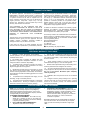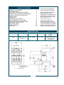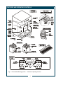
1
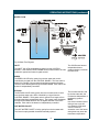
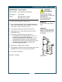
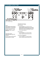
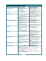
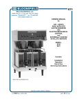
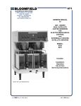
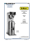
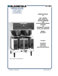
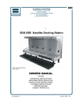
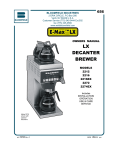
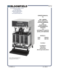
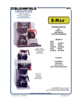
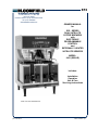
673 BLOOMFIELD INDUSTRIES 2 ERIK CIRCLE, P. O. Box 280 Verdi, NV 89439 Customer Service (775) 345-0444 Ext.502 fax: (775) 345-0569 www.wellsbloomfield.com OWNERS MANUAL for SS2 - SERIES DUAL SATELLITE COFFEE BREWERS with ELECTRONIC PROGRAMMABLE CONTROL and EXTERNALLY HEATED SATELLITE SERVERS MODEL: 9421 (SS2-HE) Includes: Installation Operation Use & Care Servicing Instructions Model 9421 Dual Satellite Brewer p/n 74340 Rev.C M673 040402 cps WARRANTY STATEMENT The prices charged by Bloomfield Industries for its products are based upon the limitations in this warranty. Seller’s obligation under this warranty is limited to repair of defects without charge by a Bloomfield Industries Authorized Service Agency or one of its sub-agencies. This service will be provided on customer’s premises for non-portable models. Portable models (a device with a cord and plug) must be taken or shipped to the closest Authorized Service Agency, transportation charges prepaid for service. All electrical equipment manufactured by BLOOMFIELD INDUSTRIES is warranted against defects in material and workmanship for a period of one year from original purchase or eighteen months from the date of shipment from our factory, whichever comes first, and is for the benefit of the original purchaser, except that; airpots carry a 30 day warranty only; dispensers i.e. tea and coffee carry a 90 day warranty; and, decanters are excluded. THIS WARRANTY IS THE COMPLETE AND ONLY WARRANTY, EXPRESSED OR IMPLIED IN LAW OR IN FACT, INCLUDING, BUT NOT LIMITED TO, WARRANTIES OF MERCHANTABILITY OR FITNESS FOR ANY PARTICULAR PURPOSE, AND/OR INDIRECT OR CONSEQUENTIAL DAMAGES IN CONNECTION WITH BLOOMFIELD PRODUCTS. In addition to restrictions contained in this warranty, specific limitations are detailed in the ADDITIONAL WARRANTY EXCLUSIONS section. Bloomfield Industries Authorized Service Agencies are located in principal cities. This warranty is valid in the United States and void elsewhere. Please consult your classified telephone directory, your food service equipment dealer, or, for information and other details concerning warranty write to: Service Parts Department Bloomfield Industries P. O. Box 280 Verdi, Nevada 89439 This warranty is void if it is determined upon inspection by an Authorized Service Agency that the equipment has been modified, misused, misapplied, improperly installed, or damaged in transit or by fire, flood or act of God. It also does not apply if the serial nameplate has been removed or service is performed by unauthorized personnel. (775) 345-0444 fax (775) 345-0569 SERVICE POLICY AND PROCEDURE GUIDE ADDITIONAL WARRANTY EXCLUSIONS 1. Resetting of safety thermostats, circuit breakers, overload protectors, or fuse replacements unless warranted conditions are the cause. 7. Full use, care and maintenance instructions are supplied with each machine. Those miscellaneous adjustments noted are customer responsibility. Proper attention will prolong the life of the machine. 2. All problems due to operation at voltages other than specified on equipment nameplates—conversion to correct voltage must be the customer’s responsibility. 8. Travel mileage is limited to sixty (60) miles from an authorized Service Agency or one of its sub-agencies. 3. All problems due to electrical connections not made in accordance with electrical code requirements and wiring diagrams supplied with the equipment. 9. All labor shall be performed during normal working hours. Overtime premium shall be charged to the customer. 10. All genuine Bloomfield replacement parts are warranted for ninety (90) days from date of purchase on non-warranted equipment. Any use of non-genuine Bloomfield parts completely voids any warranty. 4. Replacement of items subject to normal wear, to include such items as knobs and light bulbs. Normal maintenance functions including adjustment of thermostats, microswitches, and replacement of fuses and indicating lights are not covered under warranty. 11. Installation, labor and job check-out are not considered warranty. 5. All problems due to inadequate water supply, such as fluctuating, or high or low water pressure. 12. Charges incurred by delays, waiting time or operating restrictions that hinder the service technicians ability to perform services are not covered by warranty. This includes institutional and correctional facilities. 6. All problems due to mineral/calcium deposits, or contamination from chlorides/chlorines. De-liming is considered a preventative maintenance function and is not covered by warranty. SHIPPING DAMAGE CLAIMS PROCEDURE NOTE: For your protection, please note that equipment in this shipment was carefully inspected and packaged by skilled personnel before leaving the factory. Upon acceptance of this shipment, the transportation company assumes full responsibility for its safe delivery. IF SHIPMENT ARRIVES DAMAGED: 1. VISIBLE LOSS OR DAMAGE: Be certain that any visible loss or damage is noted on the freight bill or express receipt, and that the note of loss or damage is signed by the delivery person. 2. FILE CLAIM FOR DAMAGE IMMEDIATELY: Regardless of the extent of the damage. 3. CONCEALED LOSS OR DAMAGE: if damage is unnoticed until the merchandise is unpacked, notify the transportation company or carrier immediately, and file “CONCEALED DAMAGE” claim with them. This must be done within fifteen (15) days from the date the delivery was made to you. Be sure to retain the container for inspection. Bloomfield Industries cannot assume liability for damage or loss incurred in transit. We will, however, at your request, supply you with the necessary documents to support your claim. xi TABLE OF CONTENTS WARRANTY STATEMENT SPECIFICATIONS FEATURES & OPERATING CONTROLS PRECAUTIONS & GENERAL INFORMATION AGENCY APPROVAL INFORMATION INSTALLATION OPERATION CLEANING INSTRUCTIONS PROGRAMMING INSTRUCTIONS TROUBLESHOOTING SUGGESTIONS SERVICING INSTRUCTIONS EXPLODED VIEWS WIRING DIAGRAM SATELLITE Thank You for purchasing this Bloomfield Industries appliance. xi 1 2 4 4 5 7 10 12 17 18 20 24 25 Proper installation, professional operation and consistent maintenance of this appliance will ensure that it gives you the very best performance and a long, economical service life. This manual contains the information needed to properly install this appliance, and to use, care for and maintain or repair the appliance in a manner which will ensure its optimum performance. SPECIFICATIONS MODEL VOLTS WATTS AMPS POWER CORD 9421 120/208-240 VAC 50/60 Hz 1ø 4700 - 6250W 23.0 - 26.0A 4-wire 8 WAWG reqd (L1, L2, Neut, Gnd) not provided 1 FEATURES AND OPERATING CONTROLS Fig 1. SS-2 Satellite Brewing System Features & Operating Controls 2 FEATURES AND OPERATING CONTROLS (continued) Brewer Adjustable Legs Allows brewer to be leveled. Also allow clearance for cleaning underneath brewer. Brewing Controls Start or stop brew and select brew volume. Right and left section are independent. Also, used to program brewer in programming mode. Digital Readout Displays information pertaining to brew cycle and status. Displays programming information in programming mode. Bypass Nozzle Dilution water flows into satellite from here. Hot Water Faucet Hot water dispensed here. Nameplate Lists manufacturer, model and serial number. Also lists voltage and wattage rating of brewer. Power Key Controls brewer ON MODE and OFF MODE. System Switch (not shown) Located on lower right rear of brewer. Turns main power to brewer ON or OFF . Satellite Locator/Warmer Positions externally heated satellite on brewer. Maintains temperature of product in satellite. Warmer Switches Control individual warmers for externally heated satellite . Brew Chamber Brew Chamber Holds coffee grounds during brew cycle. Wire Rack Holds paper filter and coffee grounds in proper position in brew chamber. Satellite Brew-Thru Lid Allows entry of brewed coffee and dilution water into satellite. Minimizes splashing in the event satellite is tipped. Handles Allow the satellite to be safely carried. Nameplate Lists manufacturer, model and serial number. Also lists voltage and wattage rating of satellite. Serving Faucet Fresh coffee dispensed from satellite here. Sight Glass Check the level of coffee remaining here. Drip Tray (optional) Optional drip tray catches drips and spills from serving faucet. Easily removed for cleaning. 3 GENERAL INFORMATION AND PRECAUTIONS WARNING: Electric Shock hazard All servicing requiring access to non-insulated electrical components must be performed by a factory authorized technician. DO NOT open any access panel which requires the use of tools. Failure to follow this warning can result in severe electrical shock. CAUTION: Burn Hazard Surfaces of this brewer can be hot and can cause burns on contact. This appliance is intended for use in commercial establishments only. This appliance is intended to brew hot beverage, specifically coffee, for human consumption. No other use is recommended or authorized by the manufacturer or its agents. Operators of this appliance must be familiar with the appliance use, limitations and associated restrictions. Operating instructions must be read and understood by all persons using or installing this appliance. Cleanliness of this appliance is essential to good sanitation. Read and follow all included cleaning instructions and schedules to ensure the safety of the food product. Surfaces of the brewer, brew basket and satellite can be hot to the touch, and may cause burns on contact. Disconnect the brewer from electrical power before performing any maintenance or servicing. DO NOT submerge satellites in water. DO NOT splash or pour water over, onto or into any controls, control panel or wiring. Any procedure which requires the use of tools must be performed by a qualified technician. This manual is considered to be a permanent part of the appliance. This manual and all supplied instructions, diagrams, schematics, parts breakdown illustrations, notices and labels must remain with the appliance if it is sold or moved to another location. This appliance is made in the USA. Unless otherwise noted, this appliance has American sizes on all hardware. AGENCY APPROVAL INFORMATION This dual satellite brewing system is and listed under E9253 listed under E9253. E9253 This dual satellite brewing system meets NSF Standard 4 only when installed and maintained per the instructions in this manual. E9253 STD 4 4 INSTALLATION INSTRUCTIONS INSTALL LEGS The brewer is provided with 4" adjustable legs and rubber feet. Be sure the legs are securely screwed into the base of the brewer, and that the rubber feet are properly installed. LEVEL THE UNIT The adjustable legs allow the brewer to be leveled. Set the brewer in its ultimate operating location and check for level with a spirit level Adjust the brewer for level from front-to-rear, and from sideto-side. Be sure all four feet rest firmly on the counter. PLUMBER’S INSTALLATION INSTRUCTIONS IMPORTANT: This equipment must be installed in accordance with the Basic Plumbing Code of the Building Officials and Code Administrators International (BOCA), and the Food Service Sanitation Manual of the Food and Drug Administration (FDA). Also, this equipment installation must comply with all local codes and ordinances. IMPORTANT: Brewer must be installed on a water line with a full-flow pressure between 20 psi and 90 psi. NOTE: To enable the installer to make a quality installation and to minimize installation time, these tests and suggestions should be completed before the actual installation is begun. CAUTION: Hazard from Unstable Equipment Rubber feet must be installed on each leg of the brewer. Legs must be adjusted so that all four feet rest firmly on the counter. Failure to properly install the feet can result in movement of the brewer, which can cause personal injury and/ or damage to the brewer. NOTE: If water pressure varies greatly, or exceeds 90 psi at any time, a water pressure regulator must be installed. Plumbing installer must supply the regulator. SCREW INTO BREWER FRAME Brewer must be connected to a potable water supply. Bloomfield recommends not less than 1/4” copper tubing for installations of 12’ or less, and not less than 3/8” copper tubing for installations exceeding 12’. Brewer should be connected to a COLD water line. ADJUST FOR HEIGHT NOTE: DO NOT use a saddle tap for this water line connection. ATTACH RUBBER FEET A shut-off valve must be installed between the main water supply and the brewer. Plumbing installer must supply the shut-off valve. A 1/4-turn ball valve is recommended. Fig. 2 Adjustable Legs Bloomfield recommends the use of a water strainer to help prevent deposits in the brewing system. CAUTION: Flush the water line before connecting to the brewer. ELECTRICIAN’S INSTALLATION INSTRUCTIONS Brewer requires a dedicated single-phase circuit: Model 9421 120/240 Volt AC, 50/60 Hz 4-Wire 40 Amps. IMPORTANT: Minimum voltage is 208 Volt AC 5 Electric Shock Hazard Brewer must be properly grounded to a reliable earth ground to prevent possible shock hazard. Do not assume a plumbing line will provide such a ground. Electrical shock may cause serious injury. INSTALLATION INSTRUCTIONS (continued) IMPORTANT: Initial set-up must be performed by a qualified installer or qualified service technician. Improper set-up will damage the brewer and void the warranty. DO NOT CONNECT POWER TO BREWER WITH SATELLITES IN PLACE. NOTE: If “NO WATER SENSED” error message is displayed: * Disconnect brewer from electrical power. * Review Plumber’s Installation Instructions * Check inlet solenoid for debris and verify proper operation NOTE: Brewer will not operate unless the appropriate WARMER SWITCH is turned ON. INITIAL SET-UP INSTRUCTIONS Plumber’s and Electrician’s installation procedures must be completed before proceeding with the set-up. Be sure all electrical connections are secure, and that all plumbing connections are secure and leak-proof. CHECK BREWER FOR PROPER CONFIGURATION Make sure spray disk gaskets are in place INSIDE of spray heads. Make sure spray disks are properly installed. Check hot water faucet for proper operation and leaks. START BREWER OPERATION When power is first applied to the brewer, the display will read “BLOOMFIELD” briefly, and a “beep” will sound. Press the POWER key. The inlet valve will energize and the tank will begin filling. The display will read “Filling…” Fill time for the tank is approximately 13 minutes. If water is not sensed at the water level probe within 20 minutes, the brewer will shut down and the display will read “NO WATER SENSED” error message. When tank has filled, TANK HEAT LED will glow and display will read “Heating…”. Slide satellites into position. Make sure satellites are properly aligned, the WARMER SWITCHES are turned ON and the SATELLITE LEDs are lit. Allow 30 minutes for initial water heat-up. Time will vary with incoming water temperature. When the tank water is up to the Precise Temperature for Brewing™, the TANK HEAT LED will turn off. FINAL CHECKS After initial heat-up and before brewing, draw water from the hot water faucet until the inlet solenoid actuates. This will prevent volume differences to the initial brew caused by water expansion. Verify brew water temperature. It should be 200ºF ±5ºF. Check and adjust water delivery volumes. Disconnect brewer from electrical power. Inside top of the brewer for leaks. Reassemble brewer and reconnect power. 6 OPERATING INSTRUCTIONS Fig. 3 Control Panel GETTING STARTED Check the brewer and satellites: Check that the brewer is clean and the drip tray (if used) is empty. Check that the satellites are empty and clean with lids properly installed. Check the spray heads: Remove the brew chambers. Check the spray heads. Verify that the spray disks are clean and properly installed. Verify that the gaskets are properly installed inside the spray heads. Check the brew chambers: Check that the brew chamber is clean. Check that the wire basket is properly installed in the brew chamber. DAILY START-UP Press system switch (back of brewer, lower right corner) to ON: Brewer will “beep” and briefly display the message BLOOMFIELD. Press POWER KEY to enter ON mode: Brewer water tank will begin filling. The message FILLING will be displayed. When the tank is full, TANK HEAT LED will glow, and the message HEATING is displayed indicating that the tank heater is ON. Press WARMER SWITCHES to OFF until you are ready to begin a brew. When the tank is filled and up to temperature, time and date are displayed. The brewer is ready to operate. 7 NOTE: If water is not sensed at the water level sensor within 20 minutes: Heater will be disabled Error message NO WATER SENSED will be displayed Call the PHONE NUMBER displayed for service. OPERATING INSTRUCTIONS (continued) Fig. 4 Operating Controls BREWING COFFEE Prepare the Brew Baskets: PAPER FILTER WIRE RACK BREW CHAMBER Make sure the wire rack is properly installed in each brew chamber. Insert one (1) Bloomfield paper filter into each brew chamber. Make sure the filter is properly supported by the wire rack. Add a measured amount of grounds to each brew basket. Gently shake the basket to level the grounds. Slide one brew chamber under each brew head. Insert Satellites: Fig. 5 Brew Basket CAUTION: Burn Hazard Basket and contents are hot to the touch and may cause burns on contact. Slide one satellite under each brew chamber until it is fully seated. Press appropriate WARMER SWITCH to ON. SATELLITE LED for left or right side will glow. Select Brew Volume: Press either the 1/2 GALLON, 1 GALLON or 1-1/2 GALLON key. The corresponding LED will glow. Start the Brew: Press either the right or left START BREW key. The LED for the selected side will glow. NOTE: The brew can be cancelled at any time by pressing the BREW STOP key. At the end of the brew, the brewer will beep. When the TANK HEAT LED goes out, the brewer is ready to run another brew cycle. Empty the Brew Basket: Discard the grounds and the paper filter. Rinse the brew chamber under clear water. 8 OPERATING INSTRUCTIONS (continued) WATER FLOW Fig. 6 Water Flow Diagram INLET The INLET VALVE is controlled by a signal from the CONTROL BOARD. If the WATER LEVEL PROBE does not detect water, the inlet solenoid is opened until water is again sensed. The SS-2 Brewer has two independent brewer systems sharing a common hot water tank. BREW The BREW VALVE fed by gravity from the hot water tank, and is controlled by a signal from the CONTROL BOARD. The brew valve is opened for a length of time as determined from programmed values. The brew valve discharged through the BREW HEAD. Each half of the brewer is independently controlled. BYPASS The BYPASS VALVE fed by gravity from the hot water tank via a tee from the brew water tube, and is controlled by a signal from the CONTROL BOARD. The bypass valve is opened for a length of time as determined from programmed values. The bypass valve discharges through the BYPASS NOZZLE into the bypass channel of the brew chamber. Each half of the brewer is independently controlled. HOT WATER FAUCET The HOT WATER FAUCET is fed by gravity from the hot water tank. The faucet is spring-loaded closed and manually opened. 9 The hot water faucet is fed by the hot water tank, but is otherwise independent of the brewing systems. NOTE: Use of the hot water faucet during a brew cycle will not change the delivered volume. However, excessive use of the faucet during brew may lower the brew water temperature. CLEANING INSTRUCTIONS CLEANING INSTRUCTIONS CAUTION: Burn Hazard Brewing and serving temperatures of coffee are extremely hot. Hot coffee will cause serious skin burns. WARNING: Electric Shock Hazard DO NOT immerse or submerge satellites. Fluid may saturate the insulation and short-circuit the receptacle connectors. Electric shock may cause injury and property damage. IMPORTANT: DO NOT use steel wool, sharp objects, or caustic, abrasive or chlorinated cleansers to clean the brewer, brew baskets or satellites. PROCEDURE: Clean Coffee Brewer PRECAUTIONS: Press POWER key to OFF. Allow brewer to cool. FREQUENCY: Daily TOOLS: Mild Detergent, Clean Soft Cloth or Sponge Bristle Brush 1. Press POWER key to OFF. Allow brewer to cool. 2. Remove satellites. 3. Remove and empty brew baskets. 4. Remove spray disks and gaskets from spray heads 5. Wipe inside of spray head and area around spray head with a soft clean cloth or sponge moistened with clean water. 6. Wash spray disks in a sink using warm water and a mild detergent. A bristle brush may be used to clear clogged spray holes. Rinse spray disks with clean water and allow to air dry. 7. Wash brew baskets in a sink using warm water and a mild detergent. A bristle brush may be used to clean around the wire rack. Rinse with clean water and allow to air dry. Be sure wire racks are properly installed. 8. Remove and drain the drip tray. Rinse in a sink under warm running water. Allow to air dry, then reinstall on brewer. 9. Wipe exterior of brewer and satellites with a soft clean cloth or sponge moistened with clean water. 10. Reinstall gaskets INSIDE brew heads, then reinstall spray disks. 11. Reinstall brew chambers. 12. Reinstall satellites. Procedure is complete 10 CLEANING INSTRUCTIONS (continued) PROCEDURE: Clean Satellite PRECAUTIONS: Drain Satellite before Cleaning FREQUENCY: Twice Weekly TOOLS: Sight Glass Brush, Sanitizer Soft Clean Cloth, Bucket CAUTION: Burn Hazard Brewing and serving temperatures of coffee are extremely hot. Hot coffee will cause serious skin burns. 1. Remove and drain satellites. Remove lids. 2. Place 1 packet of Sanitizer into 2-1/2 gallons of warm tap water. Pour approximately 1 gallon of sanitizer solution into each satellite. Allow to stand for 2 minutes. 3. Drain sanitizer solution from satellite into the bucket. 4. Disassemble faucet. Brush clean with sanitizer solution. Reassemble faucet. IMPORTANT: DO NOT submerge satellite in water. IMPORTANT: DO NOT use steel wool, sharp objects, or caustic, abrasive or chlorinated cleansers to clean the satellites. 5. If necessary, disassemble and clean sight glass. a. Push down on ears on sight glass guard . Then, pull ears forward. Lift guard off of retaining clip. b. Remove sight glass tube from silicone elbow. Run the sight glass brush through the tube at least ten times. c. Reassemble the tube to the silicone elbow. Be sure the elbow has not been pulled from the satellite body. d. Reinstall the sight glass guard. 6. Reinstall lids. Install satellites on brewer. 7. Rinse satellites: With an empty brew chamber in place, press the BREW key and run 1 full cycle into each satellite. 8. Drain water from satellites. Procedure is complete Sight Glass 11 PROGRAMMING INSTRUCTIONS Fig. 7 Function Keys NEW MENU SETTINGS NOTE: Time is held in memory and is battery-backed. Clock change should only be necessary for daylight saving time, or if the brewer is moved to another time zone. This brewer can be programmed with a personal computer. Please contact your Bloomfield Representative for details Menu Program: Press POWER key to enter OFF mode. Press and hold 3rd & 6th keys for 3 seconds Advance thru menus by pressing the 1st key Advance thru items by pressing the 3rd key To exit, press 2nd key Clock Settings: Press POWER key to enter ON mode Press 3rd & 4th keys at the same time Check Tank Temperature: Press POWER key to enter ON mode Press 3rd & 6th keys at the same time 12 PROGRAMMING INSTRUCTIONS (continued) FEATURES 1. Energizing the Brewer: Turn the brewer on by pressing the POWER key. The brewer will start to fill the tank with the message on the screen “filling…”. With the proper water supply the tank should be filled in about 2½ minutes. Once filled, the heating element will come on until the proper tank temperature has been reached, (which will take about 20 minutes on 120-Volt models or about 12 minutes on 120/240 Volt models). 2. Brewing (Precise Temperature Brewing™ — PTB™): In regular operating mode, the Satellite Brewer maintains the tank temperature within +/- 1ºF of the brew temperature. Normally this will mean that a brew will be started as soon as the BREW switch is depressed. However, there may be a slight delay if the BREW switch is depressed immediately after a brew has been completed (notably on 120v models). If the tank temperature is below the brew temperature, the brew will be delayed going into the “Brew Wait” mode, with the brew light flashing, and the message on the screen “heating…”. As soon as the correct temperature is reached the brew will commence with the BREW LED on continuously during the brew. The time remaining in the brew will count down on the display. During the brew if the BREW switch is depressed, it will be ignored. Only if the brew is complete can another brew be started. To over-ride the Brew Wait Mode, press and hold the START BREW key for 3 seconds when the brewer is in Brew Wait mode (i.e. when BREW LED is flashing). The brew will proceed immediately regardless of water temperature. This feature should only be used when testing water volume, otherwise the brew will proceed with the water below the precise brew temperature. 3. Brew Cancel: To cancel a brew in progress, or to cancel a brew waiting, depress the STOP BREW key: two beeps will sound and the BREW LED will go out. Water flowing to the brew basket will be stopped immediately, but, if there is already water in the brew basket, it will take a few moments before this drips through as coffee 4. Normal Operation (Non Brewing): When the unit is not brewing, the Brewer maintains the water temperature at the Precise Temperature for Brewing™ (PTB™). The heating element will cycle on and off automatically to maintain this temperature. The TANK HEAT LED will glow any time the heating element is energized. 13 PRECISE BREWING TEMPERATURE™: The brew cycle will not start until the water in the tank is at the proper temperature. If START BREW key is pressed and held for 3 seconds during “Brew Wait” the brew will proceed immediately. Note: the following safety features prevent multiple unattended brews: When the BREW LED is on or flashing, repeated pressing of the START BREW switch will be ignored, (there will be a beep each time it is pressed). A Brew will only be activated or put in Brew Wait when the BREW LED is off. Only one brew can be stored in “Brew Wait” at a time. PROGRAMMING (continued) ON/OFF – Normal Operation (Non Automatic Timer): To turn the brewer OFF, press the POWER key: 2 beeps will be heard and the brewer will be turned OFF, indicated by all lights being off. 5. View Water Temperature in Tank: To view the water temperature on the screen, the brewer must be ON, and not brewing or in the filling mode. Press and hold the 4th key, and depress the 6th key. The actual water temperature will be displayed for 3 seconds. To turn the brewer ON, press the POWER key: 2 beeps will sound, all lights will flash once, then the POWER LED will glow. NOTE: The HEAT LED will glow if the water temperature is too low when the brewer is turned . 6. ON/OFF – Automatic Timer Feature: The factory programmed Satellite Brewer has the automatic timer turned off. To set the automatic timer, refer to “Time Functions” Menu. If the Automatic Timer feature is programmed off, the brewer can be turned on and off by pressing the POWER key, as noted at left. When the Automatic Timer feature is programmed ON the Brewer will turn on and off automatically, at a programmed time, Monday to Friday; with a separate on and off programmed time schedule for Saturday and Sunday. Temporarily Overriding the Automatic On/Off function: While in the automatic timed OFF mode, the brewer can be started by depressing the POWER key. The brewer will remain on until the automatic programmed OFF time, when it will turn off and resume normal automatic timed functioning. Similarly, if turned OFF during the automatic timed ON mode the brewer will remain OFF until the next programmed ON time, when it will turn on and resume normal automatic timed functioning. 14 PROGRAMMING (continued) 7. Automatic Start-Up in Previous Mode: If the Satellite Brewer automatic timer is OFF (the factory setting) and power is disconnected, the brewer will start up when power is restored, in the mode it had been in prior to the power disconnection. If the Satellite Brewer has the timer setting ON and power is disconnected, the brewer will start up in the mode that it should be in at the time the power is restored. 8. Brew Volume: The Brewer can have up to 3 different brew volumes on each side. When a volume other than the standard, or first brew volume, is selected, the Brewer will complete that volume and then automatically reset to the standard, or first brew volume. To view, press the individual volume key. The brew volume will be displayed on the screen for 3 seconds. If there is no brew volume for a specific key, the screen will read “no volume prog”, (i.e. no volume programmed). 9. Clock Time – Battery Backup. The Satellite Brewer has a battery backup system which will maintain the proper time during power failures, or when the brewer is unplugged (even for very prolonged periods of time). Normally there will not be a need to set the time except for Daylight Saving Time changes, or moving the brewer to different time zones. 10. Changing Day and Time: To change time, in the OFF mode, press the 2nd key twice followed by the 1st key twice to access the time change mode. In the time change mode he screen will read “Day:” followed by the current day setting. Use the 6th key to advance the day, or the 5th key to reverse. When day has been properly set, press the 3rd key. The screen will now read “Time:” with the set time on the screen, the hour and am or pm flashing. Use the 6th key to advance the hour, or the 5th key to reverse, making sure that the am or pm is correct. When the hour and am/pm is correctly set, press the 3rd key, and the screen will read “Time:” with the set time on the screen, minutes flashing. As previously, use the 5th or 6th keys to adjust the minutes, and press the 3rd key when complete. The Brewer will return to the off mode. (Changing time can also be done in the regular programming mode.) 15 Brew Volume The 1st key is the Standard Brew Volume. When a brew volume other than standard brew volume is selected, the Brewer will complete that brew then return to the standard brew volume automatically. PROGRAMMING (continued) The factory programming has the After Hours™ mode turned OFF. While in the After Hours mode, the POWER LED will flash continuously. 12. After Hours™: The After Hours™ can be programmed to come on from 1 to 6 hours after the last brew. When the Brewer goes into the After Hours™ mode, the water in the tank will be allowed to drop from the normal brewing temperature and will reheat less frequently – this feature saves energy and extend component life. When a START BREW key is pressed the Brewer automatically reverts back to normal operation, heating the water to the Precise Temperature for Brewing™ (PTB™), before starting the brew. (The POWER LED will be on continuously and the BREW LED will flash until the correct water temperature is reached.) 13. Pulse or Pre-Infusion Volume Options: If a particular brew volume has utilized the pulse or pre-infusion option, that volume will be displayed with an asterisk (*) after the volume. As an example “Volume#2*” would indicate that the second programmed brew volume has utilized the pulse or pre-infusion program options. Keypadlock™ deters unauthorized operation of the brewer. This feature is OFF in the standard factory settings. 14. Keypadlock™: If the Keypadlock™ feature is activated, there will be no response by the brewer when the keys are pressed (except for the beep after a key is pressed). To temporarily “unlock” the keypad, press and hold the 2nd key for 6 seconds. A beep will sound, indicating the keypad is temporarily “unlocked”, — a brew can be initiated, etc. The keypad will remain unlocked until the brew is completed, then automatically return to keypadlock™ mode. If a brew is not initiated 60 seconds after “unlocking”, the system will time out and return to the “locked” position. 15. View Filter Statistics: To view filter statistics, from the OFF mode, press and hold the 6th key, and touch the 3rd key to viewTotal Water Volume (TotalVol.) Touch the 3rd key again to view the filter life (FltrLife:). The percentage of the filter that has been used will be displayed. 16 TROUBLESHOOTING SUGGESTIONS DESCRIPTION OF PROBLEM POSSIBLE CAUSE SUGGESTED REMEDY No lights or heat Unit not plugged in or circuit breaker tripped Reset circuit breaker Plug brewer into electric power Power switch OFF Turn power switch ON No heat Hi-limit safety tripped Allow brewer to cool, verify water level, reset hi-limit Brewer overflows Water level probe corroded Clean water level probe Poor ground connection Verify ground connection Dirt in inlet valve or valve damaged Replace inlet valve Brew valve damaged Replace brew valve Too many paper filters or wrong filter used. Use one genuine Bloomfield paper filter per brew Chamber discharge hole plugged Clean brew chamber Improper programming Correct program (see pg. 12) Connected to wrong voltage Verify supply voltage Scale build-up on heating elements De-lime hot water tank Damaged heating element Replace element Insufficient water pressure Brewer must be operated on a dedicated water line. Other equipment on line may be robbing water volume. Plugged water line strainer Clean strainer Not properly seated Seat satellite in receptacle Fuse blown Correct problem, replace fuse Damaged satellite receptacle or wiring Determine/repair damage to satellite Damaged brewer receptacle Repair/replace receptacle Satellite shorts out Wet insulation Disassemble satellite, allow to dry completely before reassembly Poor coffee quality Improper programming Correct programming Brew chamber overflows Heats slow Slow to fill Satellite does not heat Also: Keep brewer and servers clean. Install a taste and odor filter in water supply, and replace cartridges regularly. Use a quality coffee with a consistent roast. Use proper grind and amount of coffee per brew. 17 SERVICING INSTRUCTIONS CAUTION CHEMICAL BURN HAZARD Deliming chemicals are caustic. Wear appropriate protective gloves and goggles during this procedure. Never siphon deliming chemicals or solutions by mouth. This operation should only be performed by qualified and experienced service personnel. IMPORTANT: DO NOT spill, splash or pour water or deliming solution into or over any internal component other than the inside of the water tank. IMPORTANT: DO NOT allow any internal components to come into contact with the deliming solution. Take care to keep all internal components dry. NOTE: Repeat steps 4 and 7 as required to remove all buildup. PROCEDURE: Delime the Water Tank PRECAUTIONS: Disconnect brewer from electric power. Allow brewer to cool. FREQUENCY: As required (Brewer slow to heat) TOOLS: Deliming Solution Protective Gloves, Goggles & Apron Mild Detergent, Clean Soft Cloth or Sponge Bristle Brush, Bottle Brush Large Sink (or other appropriate work area) 1. Disconnect brewer from the electrical supply. 2. Remove the brewer top panel, then remove the tank lid assembly. Do not disconnect the tank assembly at this time. 3. Siphon all water from the hot water tank. 4. Mix 10 gallons of deliming solution according to the manufacturer’s directions. Carefully pour the deliming solution into the water tank. Lower the lid assembly back onto the tank. Allow to sit for 30 minutes, or as directed by the chemical manufacturer. 5. At end of soaking period, reconnect brewer to electrical power. Install the brew chamber without filter paper or grounds. Place an empty satellite under the brew chamber. Force a 1-1/2 gallon brew: a. Press the 1-1/2 gallon key b. Press the brew key, then press and hold the brew key until a brew is initiated. Empty the satellite and repeat for the other side. 6. Disconnect brewer from electrical power and allow to cool. 7. Remove lid assembly from tank. a. Using a stiff bristle brush, scrub internal components to remove lime and calcium build-up. b. Thoroughly rinse internal components of lid assembly with clear water. c. Store lid assembly in a safe location. 8. Using a stiff bristle brush, scrub exposed portions of the heating element and the inside surfaces of the tank to remove lime and calcium build-up. 9. Siphon all solution from the tank. 18 SERVICING INSTRUCTIONS (continued) 10. Reinstall tank lid assembly into hot water tank. Make sure the lid gasket is properly in place, then reinstall the holddown clamps. 11. Remove spray disks and gaskets. Rinse both brew heads with clean water. Using a stiff brush, scrub spray disk to remove any lime or calcium build-up. Reinstall gaskets and spray disks. 13. Reconnect brewer to electrical supply . 14. Install the brew chamber without filter paper or grounds. 15. Place an empty satellite under the brew chamber. Run at least five 1-1/2 gallon brew cycles and discard all water generated at the end of each cycle. Repeat for the other side. 16. Rinse satellite with clean water. Reinstall one empty satellite under each brew chamber. Brewer is ready to use. 19 NOTE: Normally, silicone hoses do not need to be delimed. Should deliming hoses become necessary, Bloomfield recommends replacing the hoses. EXPLODED VIEW CABINET AND EXTERIOR COMPONENTS 20 21 EXPLODED VIEW 3 INTERIOR COMPONENTS 20 2 27 35 24 28 11 27 12 23 44 25 22 29 4 13 43 5 38 42 6 8 7 14 29 36 30 3 37 21 3 48 9 26 18 39 32 19 41 1 47 49 34 34 16 46 31 17 50 33 22 45 10 30 40 15 ITEM SERVICE # 1 84427 VALVE ASSEMBLY 2 83778 3 DESCRIPTION QTY ITEM 1 31 RETAINING CLIP TANK LID 4 32 NUT KEP 8-32 SS 22 33 SERVICE # DESCRIPTION QTY BRACKET BYPASS VALVE 2 82148 WASHER LOCK 1 55485 NUT 1/4-20 (pk 100) 1 SCREW 10-32 8 4 8043-12 GASKET COVER TANK 1 34 D20002-3 5 8812-57 FITTING UNION 1/4 x 1/4 1 35 83313 PROBE THERMISTOR 1 6 8710-10 NUT HEX BR 7/16-20 x 1/8 1 36 83414 SHIELD SAFETY THERMO 1 7 84370 TUBE ASSY INLET 1 37 83415 NUT 6-32 x 1" LG 2 8 8551-53 WASHER SS 1 38 8540-4 TUBE 90º COPPER 1 9 8783-1 FAUCET HOT WATER 1 39 SA 9052 STRAINER 1 BRACKET OUTLET VALVE 2 40 83571 INSERT SPRAY HEAD SS2 2 7200-6X SCREW PAN SS 8-32 x 5/16" 2 WASHER FLAT SS #8 2 10 11 83521 PROBE ASSY WATER LEVEL 1 41 12 83532 SLEEVE WATER LVL PROBE 1 42 13 82390 GROMMET .375 1 43 3-100 SCREW 6-32 x 1/4 SS 2 14 83540 TUBE SILICONE .312 x 23" 1 44 84063 GROMMET .510 OD x .250 ID 1 15 83152 ELBOW SPRAYER 2 45 82396 GROMMET ADAPTER BYPASS 2 TANK WELD ASSY SS-2 1 46 84364 TEE PLASTIC 1/2 BARB 2 ELEMENT 240V 3000W 2 47 SCREW PAN 4mm x 6mm SS 2 BRACKET SOLENOID 1 48 84367 TUBE TEE TO BYPASS 2.4" 2 16 17 84344 18 19 83309 GASKET TANK HEATER 2 49 84368 TUBE TEE TO OUTLET 2.8" 2 20 84343 FILL TUBE 90º BEND 1 50 84369 TUBE VALVE TO GROMMET 1" 2 21 83312 THERMOSTAT HI-LIMIT 1 22 83318 PLUG TANK LID .510 DIA 2 23 83319 PLUG TANK LID .298 DIA 1 24 83320 PLUG TANK LID .687 DIA 1 25 83325 TANK LID ASSY 1 26 84336 TUBE TANK TO TEE 2.0" 2 27 8043-11 ELBOW OUTLET 2 28 83384 TUBE VENT EXTENSION 2 29 83537 TUBE SILICONE 9" 2 30 83388 VALVE DISPENSING 4 23 WIRING DIAGRAM 24 SATELLITE EXPLODED VIEW & PARTS LIST SATELLITE MODEL 9440 ITEM PART NO. 1 2 83863 3 84313 4 84341 4.1 84390 4.2 8700-25L 4.3 84392 4.4 84394 4.5 8600-26 4.6 84395 4.7 84489 4.8 84488 4.10 84396 5 84299 6 84300 7 84354 8 8043-13 9 10 11 DESCRIPTION WELDMENT, SATELLITE TANK LID ASSY HANDLE / FAUCET GUARD FAUCET & SHANK ASSY FAUCET, MODEL ES SEAT CUP, #3S10 HANDLE, #13SBE-SNAP C-RING #18-1 NUT HEX SHANK WASHER, FIBRE FERRULE SHANK ASSY HOUSING, SIGHT GAUGE BRACKET, SIGHT GAUGE TUBE, SIGHT GAUGE ELBOW SCREW, 8-32 TRS HD BLK OXIDE SCREW, 8-32 TRS HD SS DECAL, SATELLITE 25 QTY 1 1 1 1 1 1 1 1 1 1 1 1 1 1 1 1 1 1 1 1 Bloomfield Industries proudly supports CFESA Commercial Food Equipment Service Association Bloomfield Industries, Inc. Division of Carrier Refrigeration PO. Box 280 Verdi, NV. 89439 Telephone (775)345-0444 Service: (888)492-2782 Fax (888)492-2783 website: www.wellsbloomfield.com Bloomfield Industries Canada Limited Division of Carrier Refrigeration 5850 Keaton Cresent Mississauga, Ontario, Canada L5R 3K2 Telephone (905)507-1700 Fax (905)507-1777 Toll Free (877)507-1700 website: www.bloomcan.com e-mail: [email protected]