1
Owner's
Manual
®
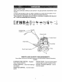
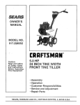
5.0 HI=
24 raNCHTINE WIDTH
FRO
E T LLER
Model No.
917.292301
Safety
,, Assembly
Operation
,_Maintenance
,, Repair Parts
CAUTION:
Read and follow all
Safety Rules and Instructions
before operating this equipment
Sears,
Roebuck
and Co., Hoffman
For answers to your questions
about this product, Calf:
1=800=659=5917
Sears Craftsman Help Line
5 am - 5 pro, Mort - Sat
Estates,
IL 60179
Warranty ........................................................... 2
Safely Rules ....................................
,......... 2
Product Specifications
.............................. 4
Assembly .....................................................
6
Operation ............................................. 3 & 7
Maintenance
...........................................
1t
LIMITED
ONE YEAR WARRANTY
Service and Adjustments ........................ 13
Storage .............................................. 3 & 16
Troubleshooting
..............................................I7
Illustrated Parts List ...............................
19
Parts Ordering
ON CRAFTSMAN
...................................
Back Cover
TILLER
For one (1) year from date of purchase, when this Craftsman 'Tiller is maintained, lubricated, and tuned up according to the operating and maintenance
instructions in the
owner's manual, Sears will repair free of charge any defect in material or workmanship.
This Warranty does not cover:
o Expendable items which become worn during normal use, such as tines, spark plugs,
air cleaners and belts.
° Repairs necessary because of operator abuse or negligence, including bent crankshafts and the failure to maintain the equipment according to the instructions contained in the owner's manual..
. If this Craftsman Tiller is used for commercial
or rental purposes, this Warranty
applies for only thirty (30) days from the date of purchase.
Warranty service is available by returning the craftsman power mower to the nearest
sears service centeddepartment
in the united states, This warranty applies only while
this product is in use in the united states.
This Warranty gives you specific legal rights, and you may also have other rights which
vary from state to state.
SEARS, ROEBUCK AND CO°, D/817WA,
TRAINING
° Read the Owner's Manual carefully. Be
thoroughly familiar with the controls and
the proper use of the equipmenL Know
how to stop the unit and disengage the
controls quickly.
,, Never allow children to operate the
equipment° Never allow adults to operate the equipment without proper
instruction.
o Keep the area of operation clear of all
persons, particularly small children, and
pe ts`
:
:,,
PREPARATION
• Thoroughly
inspect the area where the
equipment
is to be used and remove all
foreign objects.
. Disengacji_ all clutches and shil_i into
neutral before starting the,engine (too..
toO,
HOFFMAN
ESTATES,
IL 60179
o Do not operate the equipment without
wearing adequate outer garments, Wear
lootwear that wilt improve footing on
slippery surfaces.
o Handle fuel with tare; it is highly flammable.
° Use an approved fuel container,
o Never add fuel to:a running engine or'
hot engine,,
,' Fill fuel tank outdbors with extreme
care, Never fill IuBI tank indoors,
o Replace gasoline cap securely and
clean up spilled fue! before restarting.
° Use extension cords and receptacles
as
specified by the manufacturer
for all
units with electric drive motors or electric starting motors.,
= Never attempt to make any adjustments
while the engine (motor) is running
(except where specifically recommended by manufacturer).
OPERATION
,, Do not put hands or feet nearor under
rotatingpads.
o Exerciseextremecautionwhen operat-
MAINTENANCE
to avoid slipping
start to vibrate
STORAGE
°
Keep machine, attachments,
and
accessories
in safe working condition°
o Check shear pins, engine mounting
bolts, and other bolts at frequent intervals for proper tightness to be sure the
equipment is in safe working condition,
° Never store the machine with fuel in the
ing on or crossing gravel drives, walks,
or roads.. Stay alert for hidden hazards
or traffic. Do not carry passengers.
,, After striking a foreign object, stop the
engine (motor), remove the wire from
the spark plug, thoroughly
inspect the
tiller for any damage, and repair the
damage before restarting and operating
the tiller_
o Exercise caution
falling.
= If the unit should
AND
fuel tank inside a building where ignition
sources are present, such as hot water
and space heaters, clothes dryers, and
the like. Allow the engine to cool before
storing in any enclosure°
• Always refer to the operator's guide
instructions for important details if the
tiller is to be stored for an extended period.
or
abhor _
re!!ly, stop the engine (motor) and check
immediately' for the cause. Vibration is
generally a warning of troubler
,, Stop the engine (motor) when leaving
the operating position,
o Take all possible precautions
when leaving the machine unattended°
Disengage
the tines, shift into neutral, and stop the
engine.
,, Before cleaning, repairing, or inspecting,
shut off the engine and make certain all
moving parts have stopped
Disconnect
the spark plug wire, and keep the wire
away from the plug to prevent accidental
starting.. Disconnect the cord on electric
motors._
,_kCAUTION:
Always disconnect spark
plug wire and place wire where it cannot
contact spark plug in order to prevent acct...
dental starting when setting up, transporting, adjusting or making repairs°
WARNING:
The engine exhuast from this
product contains chemicals known to the
State of California to cause cancer, birth
defectd, or other reproductive
harm.
o Do not run the engine indoors; exhaust
fumes are dangerous.
° Never operate the tiller without proper
guards, plates, or other safety protective
devices in place.
• Keep children and pets away.
,, Do not overload the machine capacity
by attempting to till too deep at too fast a
rate.
o Never operate the machine at high
speeds on slippery surfaces. Look
behind and use care when backing.
,, Never allow bystanders
near the unit°
° Use only attachments
and accessories
approved by the manufacturer
of the
tiller_
,, Never operate the tiller without good visibility or light.
o Be careful when tilling in hard ground.
The tines may catch in the ground and
propel the tiller forward.
If this occurs,
let go of the handlebars
and do not
restrain the machine.
3
IPRODtJCT SPECtFgCATIONS
HORSEPOWER:
&0 HP
DISPLACEMENT:
12o57 CU, IN.
(206C6)
tiller all parts and hardware you assemble
must be tightened securety
Use the correct tools as necessary to insure proper
tightness.
MAINTENANCE
GASOUNE CAPACITY:
3 Quarts
Unleaded Regular
OIL (API-SF!SGISH):
SAE 3O
(CAPACITY'. 20 oz.)
(Above 32°F)
SAE 5W-30
SPARK PLUG ;
(GAP: .030")
A Sears Maintenance
Agreement is available on this product, Contact your nearest
Sears store for details.
CUSTOMER
(Below 32°F)
Champion RJ19LM
Congratulations
on your purchase of a
Sears Tiller, It has been designed, engineered and manufactured
to give you the
best possible dependability
and performance.
Should you experience any problems you
cannot easily remedy, please contact your
nearest authorized Sears Service'
CentedDepadment.
We have competent,
well4rained
technicians
and the proper
tools to service or repair this unit.
Please read and retain this manual The
instructions will enable you to assemble.
and maintain your tiller properly, Always
observe the "SAFETY RULES",
Your new tiller has been assembled at the
factory with exception of those pars left
unassembled
for shipping purposes., To
ensure safe and p_'oper operation of yd_r
AGREEIViENT
RESPONSIBILITIES
,, Read and observe the safety rules,
o Follow a regular schedule in maintaining, caring for and using your tiller.
o Follow the instructions
under the
"Customer Responsibilities"
and "Storage" sections of this Owner's Manual,
WARNING:
This unit is equipped with an
internal combustion
engine and should not
be used o11or near any unimproved forest-covered,
brush-covered
or grass covered land unless the engine's exhaust system is equipped with a spark arrester
meeting applicable local or state taws (if
any). If a spark arrester is used, it should
be maintained in effective working order
by the operator..
In the state of California the above is
required by law (Section 4442 of the
California Public Resources Code). Other
states may have similar laws, Federal
laws apply on federal lands. See your
Sears Authorized Service Center for spark
arrester., Refer to the Repair Parts section
of this manual for part number,
i
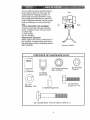
These accessories
were available, when the tiller was purchased.
They are also available at most Sears Retail outlets and Service Centers.. Most Sears Stores can order
repair parts for you when you provide
the model
number
of your tiller,
ENGINE
STABILIZER
TILLER
MAINTENANCE
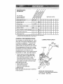
Your new tiller has been assembled
at the
Front
factory with exception of those parts left
unassembled
for shipping purposes, To
ensure safe and proper operation of your
tillre all parts and hardwa[e you assemble
must be tightened securely. Use the correct
tools as necessary to insure proper tightnesso
TOOLS REQUIRED FOR ASSEMBLY
Left
Right
A socket wrench set will make assembly
easier. Standard wrench sizes are listed.
(1) Utility knife
(t) Pair of pliers
(2) 1/2" wrenches
OPERATOR'S
POSITION
When dght or left hand is mentioned
in
this manual,
it means when you are in
the operating
position
(standing
behind
tiller handles).
CONTENTS
OF HARDWARE
__--_"
-k_J-
(t) Manual
Operator's Position
PACK
@
G
(2) Flange Locknuts
5/i 6-18 UNC
(2) Hex Nuts
5/t 6-18
(1) Plastic
Cable Clip
(2) Lock
Washers
(2) Hex Bolts
5/16_18 x 1:1/4
5/16
(1) Bofife Engine Oil
(2) Carriage
Bolts
5/16-18
5
UNC
x 2-3/8
Gr. 5
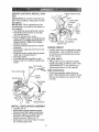
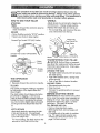
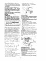
UNPACK CARTON & INSTALL HANDLE
,_CAUTION:
Be careful of exposed staples when handling or disposing of cartoning material,
IMPORTANT:
When unpacking and assembling tiller, be careful not Io stretch or
kink cable(s),
o Cut cable ties securing handle column,
• Slowly lift handle column up and slip
over handle mount.
_;
. Remove packing from carton .....
,, Secure handle column to handle mount
using two (2) carriage bolts and ti_o (2)
flange Iocknuts. Tighten botll flange
locknuts securely.
o Remove packing material from handle
assembly.
,_ insert plastic cable clip into '_lote in handle column.
,, Route tine control cable thr6ugh plastic
cable clip on handle column'.
o Cut away carton.
o Cut cable ties securing tiller to ski&
o Remove tiller from skid by pulling backwards..
T_ne
Engine Bracket Halves
Nut "A"
Depth Stake
)oft
Stake
Support Bolt
Hex Bolts, Lockwashers,
and He× nuts
HANDLE
HEIGHT
o Handle height may be adjusted to better
suit operator,
(See "HANDLE HEIGHT"
in the Service and Adjustments
section
of this manual).
TILLING
WIDTH
o 'Tilling width may be adjusted to bette{
handle your tilling conditions (See 'q_lNE
ARRANGEMENT"
in the Service and
Adjustments
TINE
"fine Control Cable
Handle Mount
_dfe
Column
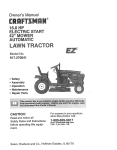
INSTALL DEPTH STAKE ASSEMBLY
Loosen nut "A".
• insert stake support between engine
bracket halves with stake spring down.
,, Bolt stake support to engine brackets
with bolts, lock washers and nuts.
Tighten securely. Tighten nut °A'L
,, Depth stake must move freely. If it does
not, loosen support bolt.
section
of this manual).
OPERATION
= Check tine operation before first use.
(See 'q'tNE OPERATION
CHECK" in the
Service and Adiustments
section of this
manual).
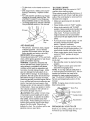
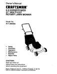
KNOWYOURTILLER
READTHIS OWNER'SMANUALANDSAFETY RULESBEFOREOPERATINGYOUR
TILLER°
Compare the illustrations with your tiller to familiarize yourself with the location of various controls and adjustments. Save this manual for future reference_
These symbols
may appear on your Tiller or in literature supplied with the product. Learn and understand their meaning.
CALmOt;I
EFi'G_'NE
F..J_'GINE
CR WA,_/_IING
oN
OFF
R_V_RS_
FAST
5LCt,'V
Forward T_ne_
Corltrol
C_OKE
FUEL
i
Oho oo o,
_
_/Tine
Reco,, Starter Hand,e//"
Sears tillers
ANS! SAFETY
conform
to the safety standards
Institute.
FORWARD TINE CONTROL
tines in forward direction.
THROTTLE
speed.
__
MEETS
CHOKE CONTROL
cold engine.
OIL
,- Engages
- Used when starting
CONTROL
_'_--
T_nes
REQUIREMENTS
of the American
National
Standards
DEPTH STAKE - Controls forward speed
and the depth at which the tille_ will dig.
RECOIL
a
STARTER
start the engine°
- Controls
Shield
engine
7
HANDLE
- Used to
_The
operation
of any tiller ban result in foreign objects thrown
into the
'[,'_,jeyes,
which can result in severe eye damage.
Always wear safety glasses
_or
eye shields before starting your tiller and while tilling.
We recommend
wide vision safety mask over spectacles
or standard
safety glasses,
a
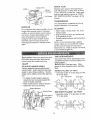
HOW TO USE YOUR TILLER
WHEELS
STOPPING
TINES
• Release forward fine control to stop forward movement,
Adjust wheels by removing the hairpin clip
and clevis pin. Change wheel position.
Replace the hairpin clip and clevis pin.
o For normal tilling, set wheels at the second or third hole from the top_
ENGINE
i = Move throttle control to "STOP" position.
!
_ Never use choke to stop engine,
Forward Tine Control "OFF (UP) Position
pth Stake
Forward
Position
Wheel _
Stake Spring and ClevisPin
TRANSPORTING
_... Choke
Control
,_.CAUTION:
AROUND
Control
_FORWARD
forward
line control
to handle.
TILLING
The speed and depth of tilling is regulated
iby the position of the depth stake and
i ,vheel height.
o Transport in upright
oil leakage.
BEFORE
STARTING
IMPORTANT:
Be very
dirt to enter the engine
adding oi! or fuel. Use
and store in approved,
containers.
Use clean
!The depth stake should always be below
it he wheels for digging.
It serves as a
,rake to slow the tiller's forward motion to
'i nable the tines to penetrate the ground_
_lso, the more the depth stake ]stowered
_to the ground the deeper the tines will
1 .
tEPTH
THE YARD
o Tip depth stake forward until It is held by
the stake spring°
o Push tiller handles down, raising tines
off the ground°
o Push or puil tiller to desired location°
AROUND TOWN
o Disconnect spark plug wire,
. Drain fue_ tank.
OPERATION
i_o Squeeze
TILLER
ing, allow tiller engine and muffler to cool.
Disconnect spark plug wire. Drain gaso,line from fuel tank_
. hrottle
TINE
YOUR
Before lifting or transport-
position
to prevent
ENGINE
careful not to allow
when checking or
clean oil and fuel
clean, covered
fill funnels.
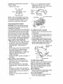
FILL ENGINE WITH OIL
• Remove hang tag from engine.
• With engine level, remove engine oil
filler plug,
• Fill engine with oil to point of overflowing, For approximate capacity see
"PRODUCT SPECIFICATIONS
on
page 4 of this manual,
STAKE
djust depth stake by removing tile hairin clip and clevis pin. Change depth
take to desired position.
Replace the ctes pin and hairpin ciip_
,
'_
For normal tiIting, set depth stake'at the
second or third hole from the top.
8
,Tift tiller back on its wheels and then relevel
o With engine level, refill to point of overflowing if necessal¥.
Replace oil filler
plug_
._
position when starting engine.
When starting engine for the first time or if
engine t_as run out of fuel, it will take extra
pulls of the recoil starter to move fuel from
the tank to the engine.
,, For cold weather operation you should
change oil for easie[+starting
(See
OIL
VISCOSITY
CHART
in the Customer
Responsibilities
section of this manual).
,' To change engine oil, see the Customer
Responsibilities
section of this manual+
,, Make sure spark plug wire is properly
connected.
o Place throttle control in "FAST" position.
• Move choke control to full "CHOKE"
position. Grasp recoil Starter handle will1
one hand and grasp tiller handle with
other hand. Pull rope out slowty untit
engine reaches star:[ of compression
cycle (rope will pull slightly harder at this
point).
Oil Filter
Plug
ADD
,' Pull recoil starter handle quickly. Do not
let starter handle snap back against
starter, Repeat if necessary..
o If engine fires but does not start, move
choke control to half choke position+ Pull
recoil starter handle until engin e stads.
o When engine starts, slowly move choke
control to "RUN" position as engine
warms upo
GASOLINE
o Fill fuel tank. Use fresh, clean, regular
unleaded gasoline.
(Use of leaded
gasoline will increase carbon and lead
oxide deposits and reduce valve life.)
IMPORTANT:
When operating in
Temperatures
below 32°F (0°C), use fresh,
clean, winter grade gasoline to help insure
good cold weather starting
WARNING:
Experience
indicates that
alcohol blended fuels (called gasohol or
using ethanol or methanol) can attract
moisture which leads to separation and
formation of acids during storage. Acidic
gas can damage the fuel system of an
engine white in storage. 'To avoid engine
problems, the fuel system should be emptied before storage of 30 days or longer.
Drain the gas tank, start the engine and let
it run untit the fuel lines and carburetor are
NOTE: A warm engine requires less choking to start+
o Move throttle control to desired running
position.
• Allow engine to warm up for a few mira
utes before engaging tines.
NOTE: if at a high altitude (3000 feet) or
in cold temperatures
(below 32°F), the carburetor fuel mixture may need to be
adjusted for best engine performance,
See "TO ADJUST CARBURETOR"
in the
Service and Adjustments
section of this
manual
NOTE: If engine does not start, see troubleshooting
points.
empty+ Use fresh fuel next season. See
Storage section of this manual for additional information.
Never use engine or carburetor cleaner products in the fuel tank or
permanent damage may occur.
,_CAUTtON;
START
ENGINE
CAUTION;
Keep fine control in "OFF"
Spark Plug
Choke Control
Fill to within 'I/2 inch of top
lrottfe Control
of fuel tank to prevent spills and to allow
for fuel expansion+
If gasoline is accidentally spilled, move machine away from
area of spill. Avoid creating any source of
ignition until gasoline vapors have disappeared+ Do not overfill. Wipe off any
spilled oil or fuel, Do not store, spill or use
gasoline near an open flame
Recoil Starlet
BREAKING
IN YOUR
TILLER
Break-in your belt(s), pulleys and fine control before you actually begin tilling.
9
,_ Start engine, tip tines off ground by
pressing handles down and engage tine
control to start tine rotation. Allow tines
to rotate for five minutes.
,, You will find tilling mucl3 easier if you
leave a row untilled between passes.
Then go back between tilled rows.There
are two reasons for doing this° First,
wide turns are much easier to negotiate
than about4aces.
Second, the tiller
won't be pulling itself, and you, toward
the row next to it.
o Check tine operation and adjust if necessary,. See 'qINE OPERATION
CHECK" in the Service and Adjustments
section of this manual.
" Set depth stake and wheel height for
shallow tilling when working extremely
hard soil or sod. Then work across the
TILLING HINTS
._CAUTION:
Until you are accustomed
to
handling your tiller, start actual field use
with throttle in slow posilion (mid-way be..
tween "FAST" and "IDLE")..
TO help tiller move forward, lilt up the handles slightly (thus lifting depth stake out of
ground). To slow down the tiller, press
down on handles.
first cuts at normal
tf you are straining or tiller is shaking, the
wheels and depth stake are not set prop.
erly in the soil being tilled. The proper setting of the wheels and depth stake is
through trial and error and depends upon
the soil condition.
(The harder or wetter
the ground, the slower the engine and tine
speed needed. Under these poor conditions, at fast speed the tiller will run and
jump over the ground).
depth.
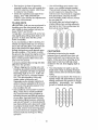
CULTIVATING
Cultivating is destroying the weeds
between rows to prevent them from robbing nourishment
and moisture from the
plants, At the same time, breaking up the
upper layer of soil crust wilt help retain
moisture in the soilo Best digging depth is
1" to 3".
A properly adjusted tiller will dig with little
effort from the operator.
o Tilling is digging into, turning over, and
breaking up packed soil before planting°
Loose, unpacked soil helps root growth.
Best tilling depth iS 4" to 6", A tiller will
also clear the soil of unwanted vegetation. The decomposition
of this vegetable matter enriches the soil.
You will probably not need to use the
depth stake. Begin by tipping the depth
stake forward until it is held by the stake
spring,.
Cultivate
up and down the rows at a
speed which wilt allow tines ta uproot
weeds and leave the ground in rough
Depending on the climate (rainfall and
wind), it may be advisable to till the soil
at the end of the growing season to further condition the soil,
condition,
growth
° Soil conditions are important for proper
tilling. Tines will net readily penelrate
dry, hard soil which may contribute to
excessive bounce and difficult handling
of your tiller. Hard soil should be' moistened before tilling; however, extremely
0
0
0
©
wet soil wifl _ball-up" or clump during tilling. Wait until the soil is tess wet ih order
to achieve the best results, When tilling
in the fall, remove vines and tong grass
to prevent them from wrapping around
the fine shaft and slowing your tilling
operation.
I0
promoting
of weeds
©0
©©
O0
©0
no
and grass.
©
©
©
0
0
0
©
0
further
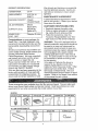
MAINTENANCE
SCHEDULE
FILL 1NDATES
AS YOU COMPLETE
REGULAR SERVICE
SERVICE DATES
=
Check Engine
Change
!
Oll Level
!
Englne Oil
Otl Plvol Points
w_
Inspect Spark Arrestor
r
/ Muffler
m
InspeclAlrScreen
L
i
I
Clean or Replace AlrCleaner Cartridge
Clean Engine Cylinder
L__
Fins
b=.,,.,,...
Replace
Spark Plug
1 - Change more otten when operaung unde[ a heavy load of' _nhigh _mblenl t_mpe_._tu_es
2 -Servtce more ellen when eperalIng tn dl_ty or clusty condili0n_,
GENERAL
RECOMMENDATIONS
LUBRICATION
The warranty on this tiller does not cover
items that have been subjected to opera-.
tor abuse or negligence_
_b receive full
value from the warranty, operator must
maintain tiller as instructed in this manual.
CHART
" T'INE
CONT
Some adjustments
will need to be made
periodically
to properly maintain your tiller,
"* ENGINE
At! adjustments
in the Service and
Adjustments
section of this manual should
be checked
at least once each season.
o Once a year you should replace the
spark plug, clean or replace air filter,
and check tines and belt for wear: A
new spark plug and clean air filter
assure proper air4uel mixture and help
your engine run better and last longer.
BEFORE EACH USE
* Check engine oil level,
o Check tine operation,
o Check for loose fasteners,.
* IDLER
LUBRICATION
Keep unit well lubricated
TION CHART") _
ARM
(See "LUBRICA* SAE 30 OR 10W30 MOTOR OIL
*_ REFER TO CUSTOMER RESPONSIBILITIES "ENGINE "SECTION.
tl
Disconnectsparkplug wirebeforeperforminganymaintenance(exceptcarbure;or adjustment)to preventaccidentalstartng of engine.
Preventfirest Keepthe enginefree of
grass, leaves,spilledoil, or fueL Remove
fuel fromtank beforetippingunit for main_,enance_
Cleanmufflerareaof all grass,
dirt,and debris,
Do not touchhot muffleror cylinderfins as
contact maycauseburns.
o Refill engine with oil.. See "FILL
ENGINE WITH OIL." in the Operation
section of this manual,
Oil Drain
(
t
_'-,:_,,_Oil Level
"Oil
Filter
Plug
ENGINE
LUBRICATION
AiR
!Use only high quality detergent oil rated
_with APt service classification
SF, SG or
iSHo Select the oil's SAE viscosity grade
!according to your expected temperature.
o Loosen airlcleaner
t
SAlE VISCOSITY
'
j
GRADES
RANGE At, R'ICIPATED BEFORE NEXT OIL CHANGE
screws,
J
o Clean by tapping
face.
gently on a fiat sur-
• if very dirty or damaged, replace cartridge_
o Clean and replace cover, Tighten screws
NOTE: Although multi-viscosity
oils (5W30, 10W-30, etc,.) improve starting in cold
,_¢eather, these multi-viscosity
oils will.,
result in increased oil consumption
when
used above 32°F (o°C). Check your
_ngine oil level more frequently to avoid
possible engine damage from running tow
on oi!.
eCUrely.
AUTION: Petroleum solvents, such
as kerosene, are not to be used to clean
cartridge. They may cause deterioration
of
the cartridge.
Do not oil cartridge,
Do not
use pressurized air to clean or dry. cartridge.
Change the oil after every 50 hours of
operation or at least once a year if the tiller
is not used for 50 hours in one year:
Check the crankcase oil level before start-
Cover
ing the engine and after each five (5)
hours of continuous use. Add SAE 30
"_ Air
Cleaner
Cadridge
motor oil or equivalent.
Tighten oil filler
plug securely each time you check lhe oil
level..
_O CHANGE
ENGINE
OIL
' _etermine temperature
range expected
, _fore oll change, All oil must meet API
., =_rvice classification
SF, SG or SH.
COOLING
Be sure tiller is on level surface.
SYSTEi_
Your engine is air cooled,
For proper
engine performance
and long life keep
your engine clean.
Oil will drain more freely when warm.
Catch oi_ in a suitable container.
Remove
one on each
side of cod#r.
° Remove air cleaner cover_
° Carefully remove air cleaner cartridge
Be careful Do not allow dirt or debris to
fall into carburetor.
i .....
TE'MPERATURE
CLEA#tER
Service air cleaner cartridge every twenty_
five hours, more often if engine is used in
very dusty c_ndltlons.
drain plug.
, Clean air screen
bristled brush.
Tip tiller fop,,vard to drain oil,.
After oil has drained completely, replace
oil drain plug and tighten securely._
Remove oil filler plug. Be careful not to
allow dirt to enter the engine.
frequently
using a stiff-
o Remove blower housing and clean as
necessary.
o Keep cylinder fins flee of dirt and chaff,
12
SPARK.
Cytinder Fins
j..... Air Screen
>
PLUG
Replace spark plugs at the beginning of
each tilling season or after every 50 hours
of use, whichever comes first, Spark plug
type and gap setting is shown in "PROD-.
UCT SPECIFICATIONS"
on page 4, of this
manual
TRANSMBSION
",four transmission is sealed and wifl only
require lubrication if it is serviced.
MUFFLER
Do not operate tiller without muffler Do not
tamper with exhaust system. Damaged
mulflers or spark arresters could create a
fire hazard. Inspect periodically
and replace if necessary, If your engine is
equipped with a spark arrester screen
assembly, remove every 50 hours for
cleaning and inspection.. Replace if damaged.
CI.EANING
° Clean engine, wheels, finish, etc.. of all
foreign matter,
,, Keep finished sudaces and wheels free
of all gasoline, oi!, etc.
,, Protect painted surfaces with automotive
type wax,
We do not recommend using a garden
hose to clean your unit unless the muffler,
air filter and carburetor are covered to
keep water out. Water in engine can result
in a shortened engine life.
TINE
,_CAUTION:
Disconnect spark plug wire
from spark plug and place wire where it
cannot come into contact with plug
eral different
HANDLE
HEIGHT
Factory assembly has provided lowest
handle height. Select handle height best
suited for your tilling conditions.
Handle
height will be different when tiller digs into
soil.
NORMAL
ways to suit your tilling or cul-
TILLING
- 24" PATH
o Assemble holes "A" in tine hubs to holes
"B" in tine shaft.,
--
,, If a higher handle height is desired,
loosen the four nuts securing handle
panel to engine brackets.
,, Slide handle panel to desired location.
,, Tighten the four nuts securely.
Engine Brackets
(1
l°lP-,l!l
in sev-
tivating needs_
.&_CAUTtON:
Tines are sharp. Wear
gloves or other protection when handling
tines.
TILLER
TO ADJUST
ARRANGEMENT
Your outer tines can be assembled
Olevis Pin
Hairpin Clip
Handle Panel
Outer Tine
"--
Inner "fine
MID-WIDTH TILLING - 22" PATH
• Assemble holes "A" in fine hubs to hole_
"C" in tine shaft.
(Also 2
on left side
of tiller)
gq
....
"%
t3
c
o -'-:_b_-l'igTg
c
NAHt_UW
i IL]L_Nru_¢Ut,_L! _VAt INL_ 12=3!4"
PATH
o Remove
Nu _L..: tr *uP_ posmon check requ_reu
adjustment,
recheck "OFF" position
adjustment
to insure tines do not rotate
when control is "OFF" (up).
outer tines_
"OF F
tL_
_--" "_o\_/
Positiion '..
Line.,_;'omr,ol
X_.\
"ON" Position
Inner Tines Only
TtNE
OPERATION
CHECK
WARNING:
Disconnect
spark plug wire
from spark plug to prevent stading while
checking tine operation.
For proper tine operation, tine control lever
must be against control body and all slack
removed from inner wire of control cable
when control is in the "OFF" (up) position_
If lever and cable are loose, loosen cable
TO REMOVE
"ON"
BELT
GUARD
o Remove cap nut and washer from side
of belt guard.
,, Loosen (do not remove) tine shield nut
on underside of tine sMetd and cap nut
on top of belt guard.
- Put! belt guard out and away from unit,
o Replace belt guard by reversing above
procedure.
Be sure slot in bottom of belt
guard is under head of line shield bolt
and all nuts are tightened securely,
clip at lower end of cable. Pull up on cable
to remove slack, without extending spring
on end of cable, and retighten cable clipo
FINAL CHECK "OFF" POSITION
• With line control "OFF" (up), push down
on handle to raise tines off the ground.
o Slowly pull recoil starter handle while
observing tines. Tines should not
rotate.
. If tines rotate, inner wire of contrql cable
is too tight which is extending lower
spring and engaging line& Loosen
cable clip and push down on cable only
enough to relieve spring tension°
'Tighten cable clip.
= Recheck in "OFF" position and adjust if
necessary.
FINAL CHECK
-line Control Cable
Cable
NOTE: When reassembling
outer tines,
be sure right tine assembly (marked "R")
and left fine assembly (marked "L") are
mounted to correct side of line shaft.
Cap Nuts and
Washer
/
Belt Guard
Tine Shield Nut
POSITION
° With tine control "ON" (held down to
handle) push down on handle to raise
tines off the ground.
o Slowly pull recoil starter handle while
observing tines. 'Tines should rotate forward.
o If tines do not rotate, inner wire of control cable is too loose. Loosen came clip
TO
REPLACE
V-BELT
Replace V-belt if it has stretched considerably or if it has cracks or frayed edges,
Belt guard must be removed to service
bell
See "-TO REMOVE BELT GUARD"
in this section of manual,
BELT REMOVAL
• Remove V-belt from transmission
first and then from engine pulley.
BELT REPLACEMENT
and pull cable up to remove stack and
retighten clip.
• Recheck in "ON" position and adjust if
necessary,
pulley
o Install new ',!-belt to engine pulley first
then to transmission pulley_
i4
Be sure belt is positioned on inside
groove of both pulleys, inside all belt
guides and rests on idler pulley,
CHECK TINE OPERATION
• See 'q']NE OPERATION
CHECK" in this
section of manual.
REPLACE
Throtlle Linkage
BELT GUARD
Belt Guide
Belt Guide
Bolt
Engine
Pulte
Idle Speed
Ad}usting
Screw
ENGINE
Maintenance,
repair, or replacement
of lhe
emission control devices and systems,
which are being done at the customers
expense, may be performed by any non,road engine repair establishment
or indF
vidual. Warranty repairs must be performed by an authorized
engine manufacturer's service outleL
TO ADJUST
CARBURETOR
The carburetor has a high speed fixed jet
and has been preset at the factory and adjustment should not be necessary.
However, minor adjustments
may be required
to compensate
for differences in fuel, temperature, altitude or load. If the carburetor
does need adjustment, proceed as follows.
IDLE RPM ADJUSTMENT
• Start engine and allow to warm
minutes.
for live
. With throttle control in "SLOW" position,,
rotate throttle linkage counterclockwise
and hold against stop while adjusting
idle speed adjusting screw to obtain
1750 RPMo Release throttle linkage.
High speed stop is factory adjusted.
Do
not adjust or damage may result°
IMPORTANT:
Never tamper with the engine governor; which is factor/set
for
proper engine speed,, overspeeding
the
engine above the factory' high speed setting can be dangerous.
If you
15
Throttle Stop
i'nmediatelyprepareyour tiller forstorage
_tthe endof the season or if the unit will
NOTE: Fuel stabilizer is an acceptable
alternative in minimizing the formation of
fuel gum deposits during storage. Add stabilizer to gasoline in fuel tank or storage
container. Always follow the mix ratio
found on stabilizer container.
Run engine
a! least 10 minutes after adding stabilizer
_ot be used for 30 days or more.
,_CAUT!ON:
Never store the tiller with
jasoline in the tank inside a building
vhere fumes may reach an open flame or
_park. Allow the engine to cool before
_l:oring in any enclosure.
to allow the s!abilizer to reach the carburetor: Do not drain the gas tank and carbu _
retor if using !uel stabilizer.
_TgLLER
:, ,Clean entire tiller (See "CLEANING"
in
i the Customer Responsibilities
section of
_this manual).
, _lnspect and replace belts, if necessary
(See belt replacement
instructions in the
Service and Adjustments
section of this
manual).
, Lubricate as shown in the Customer
ENGINE
OIL
Drain oil (with engine warm) and replace
with clean oil. (See "ENGINE" in the
Customer Responsibilities
section of this
manual).
CYLINDER
° Remove spark plug
o Pour t ounce (29 ml) of oil through
spark plug hole into cylinder.
• Pull starter handle slowly several times
to distribute oil
Responsibilities
section of this manual.
Be sure that all nuts, bolts and screws
are securely fastened.
Inspect moving
palls for damage, breakage and wear.
Replace if necessary,
, Touch up all rusted or chipped paint surfaces; sand lightly before painting.
,
o Replace
with new spark plug.
OTHER
', Do not store gasoline
to another.
ENGINE
from one season
o Replace your gasoline can if your can
starts to rust. Rust and/or dirt in your
gasoline wilI cause problems_
o If possiblei store your unit indoors and
cover it to give protection from dust and
dirt.
_:UEL SYSTEIVI
If,,/iPORTANT: It is Important to prevent
gum deposits from forming in essential fue!
system parts such as the carburetor, fuel
iilter, fue! hose, or tank during storage°
also, experience
indicates that alcohol
blended fuels (called gasohol or using
ethanol or methanol) can altract moisture
which leads to separation and formation of
acids during storage. Acidic gas can damage the fuel system of an engine while in
,forage.
Drain the fuel tank.
,, Cover your unit with a suitable protective
cover that does not retain moisture.
Do
not use plastic: Plastic cannot breathe
which allows condensation
to form and
will cause your unit to rusL
IMPORTANT:
Never cover tiller while
engine and exhaust
Start the engine and let it run until lhe
fuel lines and carburetor are empty.
Never use engine Or carburetor cleaner
products in the fuel tank or permanent
damage may occur°
Use fresh fuel next season.
16
areas are still warm.
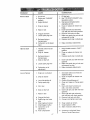
PROBLEM
Will not start
CAUSE
CORRECTION
1. Out of fuel
2, Engine not "CHOKED"
properly
3 Engine flooded
1_ Fill fuel tank_
2. See "TO START ENGtNE"in.lhe
4. Difly atr cleaner.,
4
&
Operation section
Wait several minutes before
attempting to start,
Water tn fue!,
6. Clogged fue! tank,
7. Loose spark plug wire
Bad spark plug or
Improper gap
9. Carburetor out of adjuslmenL
8,.
Clean or replace air cleaner car
lddge,
5 Drain fuel tank and carburetor,
and refill tank with fresh gasolin&
6- Remove fuel tank and clean,
7° Make sure spark plug wire is seat
ed properly on plug.
8 Replace spark plug or adjust gap.
9
Make necessary adjustments.
L
Hard to start
Throttle control nol set
2,,
3,,
4,,
properly
Dirty air cleaner
Bad spark plug or
improper gap°
Stale or dirty fuel,
5- Loose spark plug wire,
Carburetor out of
adjustment°
Loss of power
t., Engine is overloaded
2. Dirty air cleaner
3,_ Low oil levelldirty oil.
4, Faulty spark plug,
,5 Oil in fuel,
6
Stale or dirty fuel
7. Water in fuel,.
8 Clogged fue! tank.
9. Spark plug wire loose_
wire,.
10, Dirty engine air screen,
11, Dirty/clogged muffler.
t2 Carburetor out of
adjustment,
13., Poor compresslon
!7
•
,
1. Place throttle control in "FAST"
position.
2. Clean or replace air cleaner car
tridge.
3 RepJace spark plug or adjust gap
4. Drain fuel tank and refill with fresh
gasoline,
5 Make sure spark plug wire is seat
ed properly on plug.
6. Make necessary adjustments.
t_ Set depth stake and wheels for'
shallower tilling.
2, Clean or replace air' cleaner car
tridge.
3 Check oil level/change oil,
4 Clean and regap or change spark
plug.
5, Drain and clean fuel tank and
refill, and clean carburetor
6, Drain fuel tank and refill witll fresh
gasoline,
7. Drain fuel tank and carburetor,
and refilI tank with fresh gasoline
8. Remove fuel tank and clean,
9. Connect and tighten spark plug
10, Clean engine air screen.
1t Clean!replace muffler,
12, Make necessary adjustmenls
13, Contact an authorized Sears
Service CeniedDepartment
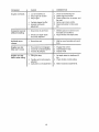
PROBLEM
CAUSE
Engineoverheats
t. Check oil level/change oil.
2. Ctean engine air screen.
3. Clean cylinder fins, air screen, muf
tier area
4 Remove and clean muffler,,
1_ Low oil level/dirty oil,
2 Dirty engine air screen,
3 Dirty engine,
4
5
Excessivebounce/
difficult
CORRECTION
Partially plugged muffler
Improper carburetor
adjustment.
5. Adjust carburetor to richer posi
tion
1. Ground too dry and hard,,
1. Moisten ground or wait lor more
favorable soil conditions
2
2
handling
Wheets and depth stake
incorrectly adjusted.
Adjust wheels and depth stake°
t, Ground too wet.
1. Wait for more favorable soil condi
tionso
Engine runs but
tiller won't move
1, Tine control is not engaged.
2. V-belt not correctly adjusted°
3., V-belt is off pulley(s).
1o Engage fine control,
2o Inspect/adjust V-belt.
3, Inspect V-belt
Engine runs but
labors when tilling
1_ Tilling too deep.
t
2, Throttle control not propedy
adjusted.
3 Carburetor out of adjustmenL
3. Make necessaryadjustments_
Sot! balls up or
clumps
_==..
=
--,,
__
I8
Set depth slake for shallower till
ing
2. Check throttle control setting.
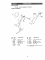
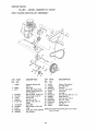
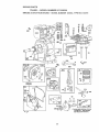
REPAIR
PARTS
TtLLER
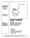
HANDLE
- .. MODEL
NUMBER
917.292301
ASSEMBLY
4
tl
13
KEY
PART
NO.
NO,
1
2
3
4
5
6
7
8
720t0520
137118
152094
9266R
3066J
151229
1200002'7
!54805
DESCRIPTION
Bolt 5/16-18 X 2-1/2
Panel, Control
Assembly, Handle Column
Grip, Handle
Cable, "line Conirot
Lever, Con{tel, Tine
Ring, Clip
Pin, Pivot
KEY
PART
NO.
NO.
9
10
11
I2
t3
14
73970500
12!I45X
110514X
98000129
STD533!07
12000059
DESCRIPTION
Locknut, Flange 5/16_18 UNC
Clip, Cable
Assembly, Paneland Tube
Nut, Flange
Bolt, Cardage 5/16-18 x 3/4
Retainer, Ring
NOTE: All component dimensions given in U.S. inct_es
1 inch = 25.4 mm
19
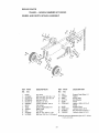
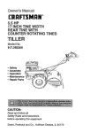
REPAIR
PARTS
TILLER
BELT GUARD
KEY
PART
NO.
NO,
1
15923_t
2 9484B
3 86777
4 74610812
5 72140404
6 121463
7 104213X
8 STD551025
9 t31158X574
10 72140405
1! 9180R
12 23230506
13 12O00028
- - MODEL
AND PULLEY
NUMBER
917.292301
ASSEMBLY
DESCRIPTION
KEY
PART
NO.
NO.
Assembly, Bracket, Belt
Guard
Clip, Cable
Screw, Hex Washer Head,
Slotted, Thread Cutting #10.,
24 x 1/2 Type D
Bolt, Hex Head 1/2-20 x 3/4
Bolt, Carriage tt4-20 1/2
Keeper, Belt
Nut, Cap t14-20
Washer 9/32x5!Bx16
Gauge
Guatd,. Belt
Bolt, Carriage 114-20x 518
14
15
16
17
18
19
20
2t
22
23
24
25
26
151223
!10528X
12000036
STD541237
161806
162290
8TD523712
106968X
7,3350500
STD541025
STD551125
t09227X
130812
V-Belt
Screw, Set, Socket, Headless
Ring, Retainer
NOTE:All component dimensions given In U.S, Inches.
! inch = 254 mm
2O
DESCRIPTION
Sheave, Transmission
Bolt, Bell Guard
Ring, Kfip
Nut, Hex, Jam 318q6
Pulley, Idler
An-n, Idler
Bolt, l--lexHead 378-16 x t-1/4
Shaft, ldlerArm
Nul, Hex, Jam 5tt6-t8
Nut, He× 1/4-20
Washer, Lock 1/4
Pad, Idler
Sheave, Englne
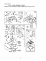
REPAIR
PARTS
TILLER
WHEEL
- - MODEL
AND DEPTH
NUMBER
STAKE
917.292301
ASSEMBLY
7
22
17
19
2O
20
19
KEY
PART
NOo
NO.
t
2
3
4
5
6
7
8
9
10
tl
t2
9t94R
74760520
STD523107
STD54103t
STD55t13t
73800800
4g21H
i952J
122233X
326J
74780828
74760524
DESCRIPTION
Pin, Clevis
Bolt, Hex Head 5/t6-t8 x 1-I/4
Boil, Hex Head 5/16-.18 x 3/4
Nut, Hex 51t6-18
Washer, Lock 5/t6
Looknul, w/washer 3/8-t6
Clip, Hairpin
Support, Depth Stake, RH
Stake, Depth
Pin, Clevis
Bolt, Fin. Hex 3/8-16 x 1,.3!4
Bolt, Hex 5/16-t8 x I-I/2 Grade 2
KEY
PART
NO,
NO.
t3
14
15
16
17
t8
I95tJ
t20958X
5388J
t21117X
9188R
STD551037
19
20
21
22
9190R
STD541437
74760516
73800500
DESCRIPTION
Support, Depth Stake, LH
Washer
Spring, Slake
Bolt, Shoulder
Whee!
Washer 13/32 x t3f16 × tl
Gauge
Bracket, Wheel
LooknuL Crown 3/8.I6
Boil, Hex Head 5/16-t8 × 1
Locknut, w/Insert 5/16-t8
NOTE'Atl component dimensions
! incll = 25 4 mm
2'I
given in US, inches
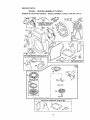
REPAIR
PARTS
TILLER
- - MODEL
NU[V_BER 917.292301
TINE ASSEMBLY
2
2
6
6
KEY
PART
NO.
NO.
1 _56926
2 STD624008
3 156924
DESCRIPTION
KEY
PART
NO,
NO.
4 156923
5 156925
6 4929H
"line, Ouler, R H
Clip, Hairpin
Tine, inner, Roll,
22
DESCRIPTION
Tine, Inner, L,H.
i]ne, O_ler, LH
Pin, Clevis
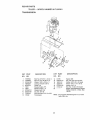
REPAIR
PARTS
TILLER
- - MODEL
NUMBER
9!7.292301
TRANSMISSaON
ii
14
12
KEY
PART
NO.
NO.
t
2
3
5
6
7
8
9
t0
tt
12
74760524
74760652
STD55t03'7
73800600
9056R574
I g49J
t g48J
STD55113I
STD54t031
74760544
151222
DESCRtP'HON
Boil, Hex 5t!6-18 x 1-1/2 Gr. 2
Bolt, Fin, Hex 3!8-16 x3-114
Washer 13/32 × 13/16 x 1t
Locknut, w/washer 3/8-16
Shield, ]]he
Bracket, Engine, R H..
Bracke!, Engine, L H.
Washer, Lock 5/t6
Nut, Hex 5!16-t8
Bolt, Hex Head 5/I6-.18 x2-3/4
Transmission
KEY
NO.
14
15
t6
t7
18
I9
20
PART
NO.
9173R
STD54143t
19091412
19092016
STD551t25
74610412
.......
DESCRIPTION
Spacer, Spttl
Nut, Hex, Keps 5/16-t8 UNC
Washer 9/32 x 718x t2 Gauge
Washer gf32 x 1-!/4 x t6 Ga..
WasI_er, Lock 1/4
Bolt, Hex I/4-28 x 3/4 Grade 5
Engine, (See Breakdown) Briggs _,
Stratton, Model No. 137202, Type
1124-Et
NOTE: All component dfmenslons given in U.S Inctles
1 inch = 25.4 mm
23
REPAIR
PARTS
TILLER
- - MODEL
NUMBER
917.292301
DECALS
4
i
3
4
KEY
PART
NO.
NO.
1
2
3
4
5
6
7
6
9
10
11
.--
158094
163320
I5B000
163049
137539
120431X
110719X
120075X
272931
273"721
162215
164786
164787
DESCRIPTION
Decal, Logo
Decal, Logo
OecaL Logo
Decal, 5HP124'
Decal, Caution, Tine Control
Decal, }-land Placement
Decat,Operation and Lubrication
Decat, Warning, Rotating Tln_s
Decal, Engine
Decal, 5HP
Decat, "Sne $h{eld (Wing Dora)
Manual, Owner's(English)
Manual, Owner's(Spanfsh)
24
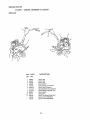
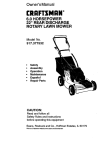
REPAIR PARTS
TILLER
BRIGGS
- - MODEL
& STRATTON
NUMBER
ENGINE
917.292301
-- MODEL
NUMBER
137202,
TYPE NO,1124-E1
f
13
i
307
_337 63_5
308
5
7
33
34
10
529
15
528
26
25
REPAIR
PARTS
TILLER--
BRIGGS
& STRATTON
fVIODEL
NUr_IBER
ENGINE
917.292301
_- MODEL
NUMBER
180
26
137202,
TYPE NO.1124-Ei
REPAIR
PARTS
TILLER
BRIGGS
- - MODEL
& STRATTON
NUMBER
ENGINE
9!7.292301
-- MODE[.
NIJM6ER
[37202,
TYPE
NO.1124_E1
334
20O
37
307
332
3
121 CARBURETOR
OVERHAUL
KIT
163
%_
(_
191
358 GASKET SET
.
5
459 _
6a9 _?_
456
I
_
1095
5 VALVE OVERHAUL
27
GASKET SET
60
TILLER
BRIGGS
& STRATTON
KEY
PART
NO.NOo
1
2
3
5
7
8
9
t0
ti
t2
497t 44
399268
299819
214040
272157
495774
27549
94621
6G578
27008O
270125
270t26
I3
14
15
16
18
19
20
2I
22
23
24
25
94221
94679
94916
492088
94388
494044
495660
294606
281658
94980
393673
222698
298904
298905
298906
298907
26
298982
299742
298983
298984
298985
27
28
- - MODEL
26026
298909
298908
29
299430
390459
30
32
33
34
35
36
37
221890
94745
211119
261044
260552
26478
222443
ENGINE
NUMBER
917.292301
-- MODEL
NUMBER
137202,
KEY
PART
NO.NO.
DESCRIPTION
Cylinder Assembly
Bushing, Cylinder
"Seal, Oil
Head, Cylinder
a'Gasket, Cylinder Head
Breather Assembly
o"Gasket, Valve Cover
Screw, Breather Mounting
Grommet, Breather Tube
"Gasket, Crankcase, Standard
0 t 5"
"Gasket, Crankcase 005"
Thick
"Gasket, Crankcase 009"
Thick
Screw, Cylinder Head 2.3/32"
Screw, GytJnderHead 2..15/32"
Plug, Pipe; Hex Socket
Cranl_sha'tt
Gear Key, Crankshaft
Cover Assembly, Crankcase
Bushing, Crankcase Cover
"Sea!, Oil
Plug, Olf.Fitler
Screw, Cover Mounting
Flywheel, Magneto
Key, Flywheel
Piston Assembfy, Standard Size
Piston Assembly .010"
Oversize
Piston Assembly 020"
Oversize
Piston Assemb!y .030"
Oversize
Ring Set, Piston, Standard Size
Ring Set, Piston, Standard,
Chrome
Ring Set, Piston .010" Oversize
Ring Set, Piston .020" Oversize
Ring Set, Piston •030" Oversize
Lock, Piston P_n
Pin Assembly, Pislon, Standard
Pin Assembly, Piston .005"
Over
Rod Assembly, Connecting
Rod Assembly, Connecting
020' Undersize Cranl_in Bore
Dipper, Connectfng Rod
Screw, Connecting Rod
Valve, Exhaust
Valve, Intake
Spdng, intake Valve
Spring, Exhaust Valve
Guard, Flywheel
40
93312
45
46
5t
55
56
58
260642
214726
273113
497442
498144
66894
60
68
65A
73
81
90
95
96
97
108
1tl
118
t 21
124
127
127A
147
I52
154
I62
163
t80
181
393152
949o4
94669
225176
222263
498298
93499
223793
497600
497230
262715
231533
495606
94913
220352
223789
231955
260575
93527
490589
271935
495405
494559
190
190A
191
94924
94919
272489
200
202
223886
262280
*
,
e
TYPE
NO.1124-EI
DESCRIPTION
Retainer, Intake Valve and
Exhaust Spring
Tappet, Valve
Gear, Cam
_,,'Gasket, Carburetor Mounting
Housing, Rewind Starter
Pulley, Rewind Starter
Rope, Rewind StaMer
(Cut to Required Length)
Handle, Rewind Starter
Screw, Housing Mounting
Screw, Hex
Screen, Rotating
Lock, Screw
Carburelor Assembly
Screw, Throttle Valve to Shaft
Throttle, Carburelor
Shaft and Lever, Throttle
Valve and Shaft Group, Choke
Spdng, Choke
Valve, Needle
Carburetor Overhaul Kit
Screw, Hex Heed
Plug, Welch
Plug, Webh
Jet, Pilot
Spdng, Throttle Adjustment
Screw, Machine, Round Head
Screw and Collar
_*Gaskel, Air Cleaner Mounting
Tank Assembly, Fue!
Cap, Fuel Tank
Screw, Fuel 'lank
Screw, Fuel Tank Mounting
,*Gasket, Fuel Tank to
Carburetor
Guide, Air
Link, Mech Governor
Included in Gasket Set (.495803)
Included in Carbu_-elorOverhaul Kt! (495606)
Included in Valve OveChaul Gasket Sol (498529)
NOTE; Att component dimensions given in U S.. Inches
1 Inch = 25.4 mm
28
REPAIR
PARTS
TILLER.
- MODEL
NUMBER
917.292301
BRIGGS & STRATTON ENGINE .,- MODEL NUMBER 137202, TYPE NO,1124-E1
KEY
PART
NO,NO.
203
205
208
209
2t2
216
219
220
222
227
' 230
256
257
300
304
305
280720
231520
262279
262948
262270
262359
494845
22t551
490649
490374
94927
223813
93543
493936
495759
690960
306
307
308
332
333
334
33'7
346
356
358
363
373
383
392
393
394
414
432
433
434
435
455
456
459
467
526
224820
94680
224'738
94877
397358
93414
802592
94896
398808
495603
t 9069
94908
89838
262328
225058
272538
220982
221377
93265
213963
93141
225121
281503
281505
280715
94914
527
223786
KEY
PART
NONO.
DESCRIPTION
Belt Crank
Screw, Shoulder
Rod, Speed Conlro{
Spring, Governor
Link, Throttle
Link, Ct_oke
Gear, Governor
Washer, Thrust
Panel, Control
Lever Assembly, Governor
Washer, Governor Lever
Crank, Bell
Screw, Slotted Hex
Mulfter; Exhaust
Housing, B_ower
Screw, B{ower Housfng
Mounting
Shteld, Cyltnder
Screw, Cylinder Shield
Cover, Cylinder Head
Nut, Flywheel
Armature Group
Screw, Armalure Mounting
Plug, Spark
Screw, Sems
Wire, Ground
Gasket Set
Flywheel Pu{ler
Nut, Hex
Wrench, Spark Plug
Spring, Fuel Pump Diaphragm
Screen, Carburetor
"Diaphragm
Washer
Cap, Spdng
Pin, Diaphragm Cover
Cover, DIa,uhragm
Screw, Diaphragm Cover
Cup, Statler
Relainer
PawL Starter
Knob, Control
Screw, Sems,'Tank Bracket
Mount,
Clamp, Breather Tube
528
529
535
536
542
552
562
592
608
611
612
613
6t4
616
621
623
634
635
676
679
680
689
741
779
780
851
869
870
871
883
9t6
966
987
968
969
971
987
995
10t2
1036
!095
2500
_ _
231550
67838
491435
494279
94897
231079
94907
'23t978
692696
231068
39t813
93935
93306
495243
396847
94943
271853
66598
393757
270382
221839
263073
262992
262570
225029
493880
211787
21 t172
262001
63709
272309
280321
492797
491588
495872
490073
94902
398970
225057
490507
499345
498529
137202-t114
491145
RPM Settings:
"
•
NOTE:
29
DESCRIPTION
Tube, Breather
Grommet, Breather 3ube
Filter, Air
Cleaner, Air
Screw
Bushing, Governor Crank
Bolt, Governor Lever
N_.Jt,He×
Starter Assembly, Rewind
Pipe, Fuel
Fuei Pipe and Clip Assembly
Screw, He× Head, Shoulder
Pin, Cotter
Crank, Governor
Switch, Stop
Screw. Shoulder
Washer, Throttle Shaft, Foam
Elbow, Spark Plug
Deflector, Exhaust, Side Outlet
Washer, Foam
Washer, Brass
Spring, Friction
Gear, Timing
Llnk, Speed Control
Ancl_or, Spdng
Cable Terminal. Ignition
Seat, Inlake Valve. Slandard
Seat, Exhaust Valve, Standard
Guide, Exhaust Valve
Guide, Intake Vafve
"Gasket, Exhaust
Rack, Gear Control
Base, Air Cleaner
Filler, Air Cleaner
Cover, Air Cleane[
Screw, Air Cleaner
Screw, Hex Head
Seat. Throttle Shaft
Lever, Brackel Assembly
Retainer, Link
Label, Nit, Emissions
Gasket Set, Va]ve Overhaul
Replacement Engine
Reptecemenl Shodbtock
Low Speed: 1750-t950
High Speed: 3400..3600
Included LnGasket Set (495603)
Included In Carburetor Overhaul Kit (495606)
Included in Valve Oved_aul Gaske_Se_(498529)
Aii component dimensions
1 inch = 25.4 mm
given {n U,,S Inches
30
31
Forthe repairor replacementpartsyou need
delivereddirectlyto your home
Call 7 am ,, 7 pm, 7 days a week
1-800-366opART
(1-800-366-7278)
Para ordenar
piezas con entrega
dom|citio
- 1-800-659-7084
a
For in-house major brand repair service
Call 24 hours a day, 7 days a week
I:800=4oREPABR
(t-800-473o7274)
Para pedir servicio
de reparaci6n
dornicilio
- 1-800-676-5811
For the location
a
of a Sears Parts and
Repair Center in your area
Call 24 hours a day, 7 days a week
1-800-488-1222
For information on purchasing a Sears
Maintenance
Agreement
or to inquire
about an existing Agreement
Call 9 am - 5 pro, Monday-Saturday
1-800-827 6655
When requesting service or ordering
parts, always provide the following
information:
Product Type
o Model Number
o Part Number
o Part Description
Amencas
164786
2,5.98
TR
Repacr SpectatJsts
Printed
in U,S,A,