1
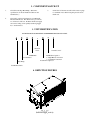
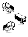
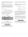
INSTALLATION INSTRUCTIONS
FOR
6535 SERIES
TWO TON HIGH EFFICIENCY
PACKAGE HEAT PUMP
TABLE OF CONTENTS
1.
2.
3.
4.
5.
6.
7.
8.
9.
10.
11.
Warnings . . . . . . . . . . . . . . . . . . . . . . . . . . . . . . . . . . . . . . . . . . . . . . . . . . . . . .
Component Match-Up . . . . . . . . . . . . . . . . . . . . . . . . . . . . . . . . . . . . . . . . . . .
Unit Identification . . . . . . . . . . . . . . . . . . . . . . . . . . . . . . . . . . . . . . . . . . . . . .
Unit Depiction Figures . . . . . . . . . . . . . . . . . . . . . . . . . . . . . . . . . . . . . . . . . . .
General Information . . . . . . . . . . . . . . . . . . . . . . . . . . . . . . . . . . . . . . . . . . . . .
Unit Installation . . . . . . . . . . . . . . . . . . . . . . . . . . . . . . . . . . . . . . . . . . . . . . . .
Duct Mounting and Configuration . . . . . . . . . . . . . . . . . . . . . . . . . . . . . . . . .
Duct and Register Specifications . . . . . . . . . . . . . . . . . . . . . . . . . . . . . . . . . . .
115 VAC Electrical Wiring . . . . . . . . . . . . . . . . . . . . . . . . . . . . . . . . . . . . . . . .
Thermostat and 12 VDC Wiring . . . . . . . . . . . . . . . . . . . . . . . . . . . . . . . . . . .
Checkout . . . . . . . . . . . . . . . . . . . . . . . . . . . . . . . . . . . . . . . . . . . . . . . . . . . . . .
2
3
3
3
5
5
6
6
8
9
11
1. WARNINGS
WARNING - SHOCK HAZARD
IMPORTANT NOTICE
To prevent the possibility of severe personal injury or
equipment damage due to electrical shock, always be sure
the electrical power source to the appliance is
disconnected.
These instructions are for the use of qualified individuals
specially trained and experienced in installation of this type
equipment and related system components.
Installation and service personnel are required by some states
to be licensed. PERSONS NOT QUALIFIED SHALL NOT
INSTALL NOR SERVICE THIS EQUIPMENT.
CAREFULLY FOLLOW ALL INSTRUCTIONS AND
WARNINGS IN THIS BOOKLET TO AVOID DAMAGE
TO THE EQUIPMENT, PERSONAL INJURY OR FIRE.
NOTE
WARNING
The words “Shall” or “Must” indicate a requirement which is
essential to satisfactory and safe product performance.
Improper installation may damage equipment, can create a
hazard and will void the warranty.
The words “Should” or “May” indicate a recommendation or
advice which is not essential and not required but which may
be useful or helpful.
The use of components not tested in combination with
these units will void the warranty, may make the
equipment in violation of state codes, may create a hazard
and may ruin the equipment.
WARNING
DO NOT PERFORM A DIELECTRIC
STRENGTH TEST (HYPOT) ON 6535
SERIES HEAT PUMPS. DAMAGE TO
PRINTED CIRCUIT BOARD MAY
RESULT.
2
2. COMPONENT MATCH-UP
1.
6535 Series Package Heat Pump. (Reference
specifications for model number breakdown and
identification.)
3.
2.
6535-3451 or 6535-335* Electronic 12 VDC Wall
Mounted Thermostat. This thermostat is pre-wired to
two electrical connectors. Both the thermostat supply
and control wiring can be quickly attached (plugged
in) to the thermostat.
6795C4351 35' thermostat cable with connector plugs
for termination at both the heat pump and electronic
thermostat.
3. UNIT IDENTIFICATION
PACKAGE HEAT PUMP MODEL NUMBER BREAKDOWN FOLLOWS:
6
5
3
5
-
8
*
Revision
Letter
24,000 BTU
Non-Exhaust
Heat Pump
1
12 VDC Control
PTCR/Start Capacitor
5. Right Hand Control Box
7. Left Hand Control Box
Tecumseh Compressor
Sub-Mounted Unit
4. DEPICTION FIGURES
3
4
5. GENERAL INFORMATION
The 6535 series package heat pumps are intended only for
installation by RV manufacturers. The units are for “off the
roof” installations and will usually be installed under the floor
of the vehicle. It is understood that the vehicle manufacturer
has provided an installation area which allows for floor cutouts
and unit mounting without cutting vital frame members or
electrical wiring and that structural members in the installation
area will not create restrictions by passing through airways
required by the heat pump.
The heat pump is powered by two separate 115 volt
20 AMP electrical services.
The heat pump is controlled by a 12 VDC electronic wall
mounted thermostat. The vehicle manufacturer must provide
the power source for the thermostat.
Avoid sliding the unit without the shipping block being
attached. The condensate drain fitting extends slightly below
the pan and will be damaged if not protected.
Conditioned air is delivered from the unit to the interior of the
vehicle through ducting that is supplied and installed by the
vehicle manufacturer. The system return air duct, return air
filter and filter retainer are also supplied by the vehicle
manufacturer.
6. UNIT INSTALLATION
CONDENSING AIR FLOW
The heat pump draws in outside air for what is referred to as
the outdoor coil. The air that is drawn across the outdoor coil
is the outdoor air flow.
3)
Any decorative grille or louver used as an
opening should have 460 square inches of
free area minimum.
The installer is responsible for the proper ducting and routing
of the outdoor air flow.
4)
Do not block or restrict the discharge air
opening (located in the bottom of the air
conditioner) with any flooring or bracing.
5)
The air being used by the outdoor coil
cannot be drawn from the underside of the
vehicle. Seal or baffle the sides and bottom
edge of the heat pump to prevent the
recirculation of air from underneath the
vehicle. Recirculation of air across the
outdoor coil will decrease both system
performance and equipment life.
6)
Do not install any other heat generating
appliance in the same cavity as the heat
pump. Additional heat in this cavity
will decrease system performance in the
cooling mode. Overall package dimensions
are shown in Figure 1. RV Products
requires that a minimum of 4 additional
inches be allowed at the wiring box end of
the unit to allow for the installation of both
the low and high voltage wiring.
7)
Insure that neither the vehicle engine
exhaust, on-board generator engine exhaust
or water heater vent exhaust are pulled into
the outdoor coil air flow. These hot
gases will both: (a) increase system
temperature reducing performance and
equipment life; and (b) the collection of
these gases chemical by-products will begin
The outdoor air flow is drawn in through the side of the air
conditioner (across the outdoor coil), and discharged out
through the bottom of the appliance (through the discharge
opening). Figures 1 and 2 show the location of both the
outdoor coil and discharge air opening.
The unit must be installed so that the side that houses both the
outdoor coil and the electrical box, faces towards the outer
skin of the vehicle. The unit is installed this way so that:
1)
the outdoor air flow will be drawn in
from the outdoors through the side of the
vehicle; and
2)
the heat pump can be serviced electrically.
To provide adequate air flow, the installer must adhere to the
following guidelines:
1)
Install the heat pump so that the outdoor
coil faces the outer skin of the vehicle; and
2)
The outdoor air path to the coil should be as
direct and non-restrictive as possible. RV
Products recommends placing the exterior
condenser air flow grille into the side of the
vehicle, directly in front of the outdoor coil.
The installer must provide the exterior air
opening and/or grille.
5
the chemical degradation of the surfaces
they collect on.
When suspending the unit from flooring or frame members, a
minimum of four threaded rods are required. Minimum rod
diameter is 5/16". The support rods and hardware must be
plated or equivalently protected against corrosion. All
threaded fasteners should be provided with lock washers,
“locktite”, “double-nutted”, or equivalently protected from
vibration loosening after installation.
In order to improve installation time and reduce down time
when servicing, RV Products recommends using drawer slides
for mounting the heat pump.
This unit must be supported from below by angle iron,
channels or RV frame members. These supports must be
located under the air conditioner and kept within the areas
shown (cross-hatched) in Figure 2. Support must be provided
in the areas indicated to both secure the compressor and
balance the system. Adding support outside of the indicated
area may interfere with either the condenser air outlet or the
condensate drain.
Condensation may at times splash out of the drain pan and
drain from the unit corners. Therefore, do not mount the air
conditioner above areas which might be damaged by exposure
to moisture.
Upon completion of the installation, verify a minimum
clearance of 14" from the bottom of the heat pump to ground
level.
7. DUCT MOUNTING AND CONFIGURATION
This system is designed for the back of the heat pump to seal
to the vehicle. The ducting for the heat pump seals to the side.
Cut-outs in the flooring provide passage for both the supply air
and the return air.
To provide both vibration dampening for the unit and air tight
seals for both supply and return air openings, RV Products
recommends the use of foam gaskets.
Gaskets do not come with the unit, they must be provided by
the installer. This allows the installer the option of either
providing their own gaskets or not using gaskets and attach
ducting directly to the heat pump.
The preferred mounting configuration is the end outlet-side
return configuration. Reference Figure 1. This system ducts
the supply air out the end while the return air is drawn in
through the side. With this configuration, one cut out will be
required to match the end opening and another to match the
back opening.
Attaching ducting directly to the heat pump is not
recommended unless the installer can provide a means for
access and quick disconnect. Generally an installation of this
type will require vehicle disassembly before some types of unit
repair can be completed.
Under no circumstances will either of the openings or
associated ducting be allowed to have a misaligned or smaller
inner perimeter than either heat pump opening.
IMPORTANT
DANGER - SHOCK HAZARD
Regardless of installation configuration,
insure that both duct connections are
air tight. Loose or leaking connections
can reduce system performance and
allow gases, odors and dirt to be drawn
in from outside the vehicle.
Do not drill or cut any openings into this
heat pump. Use only the pilot holes
already provided. Drilling new openings
and inserting screws may damage either
the refrigeration circuit or electrical
wiring causing possible equipment
damage, personal injury or death.
8. DUCT AND REGISTER SPECIFICATIONS
GENERAL INFORMATION
When ducting is attached directly to the heat pump cabinet, the
installer must utilize the screw openings already provided.
All supply air ducts, registers, return air ducts, return air filters
and filter retainers must be supplied by the installer or vehicle
manufacturer.
RV Products strongly recommends that all air distribution
systems be tested by the vehicle manufacturer in a floor mockup prior to installation in the vehicle. In doing so, the vehicle
manufacturer can insure that air volume, distribution and noise
levels are optimized.
Any ducting (supply or return) exposed to a heat source or
outdoor environment must be sealed and insulated to prevent
heat gain and decreased system performance.
6
GUIDELINES FOR SUPPLY AIR DUCTING
Should the return air filter and filter retainer be located in the
floor, a traffic duty grille will be required. The return air filter
should be located in an area where:
Minimum free area inside the supply duct is 48 square inches.
Ducting with more free area than 48 square inches will
improve system performance and vehicle cool down time.
To decrease restriction and increase air flow, the ducting
should make as few bends and turns as possible. When
corners or turns are required, it is recommended that these
turns be radiused and as gradual as possible.
1)
drapes or bed sheets cannot block the
opening;
2)
the consumer can gain easy access for
servicing.
This system is designed to operate without return air ducting.
However, the fabrication and use of return air ducting is
permissible.
The supply duct, unless made of an insulating material, must
be insulated to prevent condensation from collecting on its
exterior. Moisture condensation within the ceiling or wall
cavity can damage insulation, stain vehicle interiors or create
odors. 1/8", 3 pound density fiberglass or closed cell foam
insulation has proven effective for this purpose.
When a return air duct is utilized, it is recommended that:
Any ducting exposed to heat sources must be further insulated
to prevent significant performance degradation due to heat
gain. An example of an area capable of creating significant
heat gain is the roof area which can sometimes experience
temperatures of 160 degrees or more when exposed to direct
sunlight. For ducting in or near the ceiling, it is impossible to
provide “too much” thermal insulation.
1)
the length of the duct be kept to an absolute
minimum;
2)
the inner perimeter of the duct be kept as
large as possible.
Return air ducting will contribute to the overall pressure and
air flow loss of the system. Should the addition of return air
ducting reduce air flow below acceptable levels, then either:
GUIDELINES FOR SUPPLY REGISTERS
1)
Total free area provided by the supply air registers must equal
a minimum of 72 square inches.
the supply air duct inner perimeter will need
to be enlarged;
2)
the supply air registers will need to be
added;
3)
the return air duct inner perimeter will need
to be enlarged;
4)
the return air duct will need to be shortened;
5)
all of the above.
Free area is the size of the opening(s) that remain in a grille or
louvered panel after restrictions (the louvers) are
subtracted. Most metal and plastic grilles average 30% to 60%
open. That is the actual “free area” for the grille will be 30%
to 60% of the total opening area.
GUIDELINES FOR RETURN AIR
DUCTING AND FILTERS
All return air must be filtered. A 1-inch thick disposable
fiberglass filter is recommended. A washable filter is
acceptable if supported by a mesh or grille to prevent collapse.
7
9. 115 VAC ELECTRICAL WIRING
1.
WARNING - SHOCK HAZARD
3.
To prevent the possibility of severe personal
injury or equipment damage due to electrical
shock, always be sure the electrical power is
disconnected or off before beginning
installation.
2.
High Voltage Wiring Specifications
A)
U.L. approval requires the power supply to
be copper conductors only with minimum
#12 AWG.
B)
To prevent voltage drops greater than
10% during starting loads, insure that wiring
size matches wire sizes shown on unit
nameplate.
This unit contains a dual compressor refrigeration
system. The two compressors can either cycle
independently or operate in tandem with one another.
4.
Each compressor is connected to a separate
refrigeration circuit and a separate electrical circuit.
The first compressor and refrigeration circuit to
operate when the thermostat is calling is referred to as
“1st Stage”. The second compressor and refrigeration
circuit to operate is referred to as “2nd Stage”.
For circuit protection, adhere to the following
guidelines (per circuit):
Time Delay Fuse - Maximum 20 AMP
Circuit Breakers –
(H.A.C.R. Type) - Maximum 20 AMP
(C.S.A.) - Maximum 20 AMP
Both first and second stage systems require
power from separate 115 volt electrical circuits. The
two separate circuits connect to a high voltage
terminal board in the heat pump electrical box.
The high voltage terminal board is specifically
labeled for the two separate electrical connections.
The markings are for “CIRCUIT 1" and
“CIRCUIT 2".
5.
High Voltage Routing Specifications
When routing the high voltage supply wiring for
both circuit 1 and 2, the following guidelines must
be followed:
“CIRCUIT 1" connections supply power for the 1st
stage unit. “CIRCUIT 2" connections supply power
for the 2nd stage unit.
A)
Route all wiring per applicable local and
national electrical codes.
B)
Each circuit high voltage wiring must be
routed through a separate opening in the
outer cabinet of the wiring box. These
openings are referred to as the “power wire
entries”. See Figure 1. RV Products
provides these two openings, each opening
is a 7/8" diameter opening.
C)
Each circuit wiring must be secured at the
“power wire entry” by a U.L. listed “Rain
Tight” or equivalent electrical conduit
fitting. The fitting must be supplied by the
installer or vehicle manufacturer.
On the terminal board, the termination point for both
circuit 1 and 2 is equipped with two high-voltage
wiring lugs. Each lug is identified with either the
word “BLACK” or “WHITE”.
DANGER - SHOCK HAZARD
To prevent electrical shock due to mis-wiring, adhere to
the following procedure:
1)
Connect each circuits black (115V to GND) power
lead to the “BLACK” high voltage lug;
2)
Connect each circuits white (-0-V to GND) power
lead to the “WHITE” high voltage lug;
3)
Connect each circuits green or bare copper
ground wire to the grounding lugs located in the
electrical box. The high voltage grounding lugs
for circuit 1 and 2 are located on either side of the
high voltage terminal board.
DANGER
WHEN USING NON-METALLIC SHEATH
SUPPLY CABLES (ROMEX, ETC.), STRIP
SHEATH BACK TO EXPOSE 4-6 INCHES
OF THE SUPPLY LEADS. STRIP THE
INDIVIDUAL WIRE LEAD ENDS FOR
WIRE CONNECTION (ABOUT 3/4" BARE
WIRE). INSERT THE SUPPLY WIRES
INTO THE ELECTRICAL CONNECTOR
CLAMP. SHEATH MUST PROTRUDE
PAST CLAMP BUSHING INSIDE THE
BOX. MAKE SURE SHEATH CABLE IS
8
CENTERED IN CLAMP BEFORE
TIGHTENING IT. DO NOT OVERTIGHTEN!! THIS COULD RESULT IN
PINCHING THROUGH THE PLASTIC
WIRE INSULATION AND CAUSE
SHORTING OR “HOT” WIRES TO
GROUND (SHOCK HAZARD). THE
CLAMP IS INTENDED FOR STRAIN
RELIEF OF THE WIRES, SLIGHT
PRESSURE IS USUALLY SUFFICIENT
TO ACCOMPLISH THIS.
6.
Circuit 1 and 2 Origination Points
When both cooling systems (stage 1 and 2) cannot be
powered from a single shore line, then the system
must be wired as follows:
A.
Connect “CIRCUIT 1" to the circuit that is
powered from the vehicle shore line. This
allows stage 1 cooling to operate anytime
the shore line is connected to either the local
utility or the on-board generator.
IF OTHER THAN NON-METALLIC
CABLES ARE USED FOR SUPPLY
CONDUCTORS, APPROPRIATE
STRAIN RELIEF CONNECTORS OR
CLAMPS SHOULD BE USED.
B.
Connect “CIRCUIT 2" to the circuit that is
powered from the on-board generator.
When wired in this fashion, stage 2 cooling
will operate only when the on-board
generator is in operation.
IN NO CASE SHOULD CLAMPING
OR PINCHING ACTION BE APPLIED
TO THE INDIVIDUAL SUPPLY LEADS
(NEUTRAL AND “HOT” WIRES).
C.
D)
E)
DANGER - SHOCK HAZARD
TO PREVENT THE POSSIBILITY
OF SHOCK INJURY FROM
APPLIANCE OPERATION:
The installer must form a drip loop in the
high voltage wiring routed between the
“Rain Tight” electrical fitting and the high
voltage terminal board wiring lugs. Do not
allow excess wiring to contact electrical
terminals, sharp screw ends or edging that
can cut or damage the wiring insulation.
THE WHITE WIRE MUST BE
CONNECTED TO NEUTRAL IN THE
SERVICE BOX ENTRANCE AND THE
MECHANICAL GROUND MUST BE
CONNECTED TO A GROUNDING
LUG EITHER IN THE SERVICE BOX
OR THE MOTOR GENERATOR
COMPARTMENT.
After connecting the ground wire to the
grounding lug, verify that the ground wire
(which in some instances will be bare
copper) cannot come into contact with any
high voltage terminal.
10. THERMOSTAT AND 12 VDC WIRING
THERMOSTAT OPERATING AND WIRING
REQUIREMENTS
IMPORTANT
Current draws in excess of one amp or
shorting any thermostat wires can cause
permanent thermostat failure.
The 6535 series heat pump is designed to be operated from an
RV Products electronic wall mounted thermostat. See
component match-up section for thermostat part number and
description. The thermostat is designed to operate 12 VDC
controlled heating and air conditioning systems. The
thermostat must be operated from a 12 VDC power source.
The installer must provide the power source used to operate
both the thermostat and its control circuits. This power source
must provide one amp of continuous current at
12 VDC.
Maximum thermostat output for any load including the furnace
control wire must not exceed one amp.
The thermostat is pre-wired at RV Products with two quick
connect electrical receptacles. There is one 9 pin receptacle
carrying the control wires required to operate the heat pump,
and a 3 pin receptacle carrying the two power supply leads and
the one furnace control lead.
The thermostat is equipped with a replaceable fast-acting 2
amp fuse located on the base of the thermostat. The fuse is
designed to open if the furnace is mis-wired or there is a short
in the system. Before replacing fuse, the cause of the failure
must be located and corrected.
9
The thermostat 9 pin receptacle mates with a receptacle on one
end of the RV Products 35' pre-wired thermostat harness. See
component match-up section for harness part number and
description.
the wires required for operating the heat pump and quick
connect receptacles for both the thermostat and the heat pump
connections.
At the thermostat, the connection is completed with a square 9
pin receptacle that slides together and snap-locks in place.
When making this connection:
The thermostat harness does not include the wiring for the 3pin plug. Should the installer desire a total plug in system,
then the mate and pins for this connection must be purchased
separately. Both the receptacle and the pins are manufactured
by AMP (Aircraft Marine Products, Inc., Harrisburg, PA). In
most cases the parts can be obtained through a local supply
house.
The AMP part numbers are:
1)
2)
3 pin male receptacle #7-480700-0
female pin (for male receptacle) #350218-1
1)
verify that the connectors are properly
aligned
2)
do not use excessive force when joining the
connectors
3)
verify that the connectors have snapped
together on both sides.
The thermostat umbilical attaches to the unit with a rain-tight
fitting. To install, remove the ring-nut from the rain-tight
fitting and insert the wire end and fitting into the hole in the
wirebox side. The ring-nut will now slide over the wire end
and reinstall onto the rain-tight fitting threads. Tighten
securely. The wire end plugs into the receptacle on the
wirebox printed circuit board. Insure that the plug “snaplocks” into the receptacle.
Should the installer desire to hard wire this connection rather
than purchasing the receptacle, the three pin connector can be
cut from the wire ends, the wires stripped and spliced to
complete the required connections. For further wire
identification and function, reference Chart 2.
CHART 1
Routing of the thermostat wiring harness must comply with all
local and national electrical codes. Collect any excess
thermostat harness in the heat pump mounting compartment.
Be sure to secure the excess wiring within the compartment.
Coiling the excess harness into 3" diameter circles or larger is
acceptable.
THERMOSTAT MOUNTING
IMPORTANT
Follow the instructions packed with the thermostat to select a
location for thermostat mounting. Pay particular attention to
choose a location which is not totally isolated from air currents
and is not subject to direct discharge from an air register.
When using wire nuts to complete electrical connections,
always apply a U.L. approved electricians tape and secure the
wire nuts to the wires in a workmanlike manner.
THERMOSTAT HARNESS
RV Products produces a pre-wired 35' thermostat wiring
harness for this system. See component match-up section for
harness part number and description. This harness consists of
10
11. CHECKOUT
1.
2.
Before engaging power to any system, insure the
following:
A)
All tools have been removed from the
equipment.
B)
All wiring is attached, routed and properly
secured.
C)
All panels (both mechanical and electrical)
are in place.
D)
The thermostat system switch is placed into
the “OFF” position and fan switch is placed
in the “Auto” position.
E)
All co-workers have been warned that the
equipment is being energized.
3.
Before beginning the checkout procedure, thoroughly
read the instructions in either the thermostat
installation instructions or in the owners manual
provided with this product.
Keep in mind that the wall thermostat provides a
3 minute delay between off and on cycles.
There is also a 30 second delay between 1st and 2nd
stage cooling. This is to prevent both compressors
from starting simultaneously. To insure that the
thermostat calls for both 1st and 2nd stage cooling,
verify that the cool setpoint is well below actual
indoor temperature.
System wiring may be checked by referring to the
wiring diagram located on the back of the wiring box
door.
11
4.
After complying with steps 1 through 3, engage
power to all systems and begin checkout procedure.
5.
Test each thermostat function, such as fan modes,
heat modes and cool modes to insure proper
operation.
RV Products
A Division of Airxcel, Inc.
P.O. Box 4020
Wichita, KS 67204
1976E302 (8-05) PP