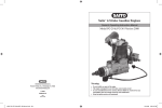
1
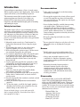
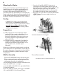
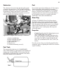
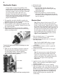
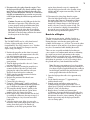
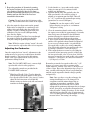
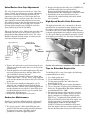
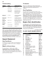
INLINE 4-STROKE ENGINES
INSTRUCTION MANUAL
FA-100Ti
FA-200Ti
2
Important
Before you attempt to
operate your
[200Ti/100Ti] engine,
please be sure to read
through these
instructions so that you
may familiarize yourself
with the various parts
and other features of
the engine. Failure to
read and follow these
instructions before you
proceed to start your
engine may result in
engine damage and the
voiding of your
warranty.
Caution
Be sure to read the
information contained
in "Safety Instructions"
3
Introduction
Congratulations on purchasing a SaitoTM 4-stroke engine.
When cared for properly, these high-quality, finely crafted
engines offer many years of modeling enjoyment.
This instruction manual has been developed to ensure
optimum performance from the Saito engine you
purchased. The instructions must be read through
completely and understood thoroughly prior to mounting
and running the engine.
Recommendations
●
●
●
Safety Instructions
This model engine will give you considerable pleasure,
satisfaction, and performance if you strictly follow these
safety instructions and take heed of the warnings as to its
safe and proper use. Remember at all times it is not a toy
but a precision-built machine with more than enough
power to cause harm if misused or if the safety precautions
are not observed.
1. Mount the engine securely in a "bench mount" or
high-quality motor mount. Never clamp the engine
in a vise.
2. When running the engine, be sure all spectators,
especially children, are at least 20 feet away.
3. Refer to the Propeller section on page 5 for the correct
size and pitch of propeller for your engine.
4. It is extremely important to balance the propeller prior
to installation of the engine. Failure to do so may
cause damage to the Saito engine and/or the airframe.
Install the propeller with the convex (curved) side
facing forward.
5. Securety tighten the propeller nut against the washer
and propeller. An anti-loosening nut (or"jam" nut) is
provided with this engine and should be used.
6. Inspect the tightness of the propeller nut prior to
each flight.
7. Keep away from the path of the propeller blades
when starting and running your engine.
8. Never allow your hands to come close to the propeller.
Utilize either a "chicken stick" or electric starter to
start the engine.
9. Discard any propeller that is nicked, scratched, cracked
or damaged in any way.
10. Make all carburetor adjustments from behind the
propeller.
11. To stop the engine, cut off the fuel supply (pinch or
disconnect the fuel line to the carburetor) or use the
throttle linkage to shut off the fuel.
Do not use hands, fingers, or any other part of the
body to stop the propeller. Do not throw any object
into a propeller to stop it.
●
●
Safety glasses or goggles be used when starting
and running your engine.
Do not run the engine in the vicinity of loose gravel
or sand. The propeller may throw such materials
into your face and eyes. The engine may also ingest
these harmful materials.
Loose clothing should be avoided when operating
your model engine. Clothing may become
entangled in the propeller, creating the possibility
of bodily harm. Also, all loose objects (screwdrivers,
pencils, nickel cadmium starters, etc.) should be
removed from your pockets so that they do not fall
into the propeller.
Keep glow plug clips and cords away from
the propeller.
Be sure glow fuel is kept in a safe place well away
from sparks, heat, or anything that can ignite
the fuel.
Beware
●
●
●
Model engines get very hot while running. Do
not attempt to handle them until they have cooled.
Always run your model engines in a wellventilated area. Similar to automotive engines,
model engines produce possible harmful carbon
monoxide fumes.
Remember that model engines produce a
substantial amount of power, more than
enough to seriously injure people and/or do
considerable damage to property. Always use
common sense, skill, and constant observation
of safety precautions.
Disassembly
Do not disassemble your Saito FA-200Ti/100Ti
engine. Only qualified individuals should perform
repairs on your FA200Ti/100Ti engine. Damage due
to improper disassembly will not be covered under
warranty. If it becomes necessary to repair the engine,
such as after a crash, you can send your engine to the
authorized service center at
Horizon Hobby, Inc.
Attention: Saito Service
4105 Fieldstone Road
Champaign, IL 61822
Phone:(217)355-9511
4
Mounting the Engine
Sturdy engine mounting is required. Mounting beams
should be integral to the airframe and should provide
sufficient support as necessary to absorb vibration. A
beam style motor mount (SAI200Ti/100Ti-95) is
provided with the FA-200Ti/100Ti to ease mounting the
engine to the firewall. Engine installation should be made
so that periodic maintenance can be performed easily, to
include the checking and adjustment of valve clearances.
1. Screw the left muffler (200Ti-73 front) into the
exhaust port of the front cylinder until it reaches the
bottom, then unscrew slightly until the muffler is at the
right exhaust outlet angle. Secure the muffler in
position by tightening the muffler nut firmly against
the cylinder head with the 12mm wrench supplied.
2. Repeat the above procedure to mount the other muffler
(200Ti-74A rear, w/pressure nipple) into the rear
engine cylinder.
Cooling
Caution: If the engine is to be mounted in an
enclosed cowl, it is essential that provision be
made to provide adequate cooling of both cylinders,
especially the rear cylinder. This may be done
through the use of baffles in the cowling to direct
airflow past the cylinders.
Suggestions
(1) If the model uses the water-cooled type engine
cowling (P-51 for example) with dummy exhaust
ports in the cowling, a hole or holes can be
provided in the dummy exhaust port to make sure
air from the propeller can pass through the cowl
and out these holes.
(2) With air-cooled type engines (the Tiger Moth for
example), an opening should be made under the
cowling located in front of the firewall so air can
pass through the cowl around the engine
and outside.
Mufflers installed on the engine
In both cases, efforts must be taken to make sure the air
passes through the cowl and around the engine and exits
the engine compartment. One method is to make baffles
that direct air around the cylinders and out the engine
compartment.
Muffler Assembly
The Saito FA-200Ti/100Ti comes with exhaust pipes.
These are adequate for most applications: however,
many modelers will prefer to use the optional flexible
exhaust pipes for many scale applications.
Use the following procedure to install each muffler to the
engine.(FA-200Ti is used as example)
For the FA-200Ti, SAI182TD-111-1 and SAI182TD-111-
2 are the Part Numbers
For the FA-100Ti, the flexible exhaust pipe is SAI100Ti111-1 and SAI100Ti.111-2(w/Pressure Fitting)
Flex mufflers mounted
Note:Mufflers shown are for comparison purposes only.
5
Carburetor
Fuel
The carburetor is located on the right side of the engine
as shown in the photo below. The FA-200Ti/100Ti does
not utilize a choke device, as the engine draw is sufficient
for priming by putting your fingers over the muffler
exhaust openings and turning the propeller over several
times (without the glow driver(s) attached).
For maximum protection and longevity of Saito engines,
Saito recommends a high-quality fuel containing
10-15% nitro methane, such as Hangar 9® Aero-Blend,
Omega. Cool Power, Power Master, etc. Use of fuels
composed entirely of castor oil is not recommended. A
mix of synthetic-castor oil is acceptable and can be
found in the various fuels described above.
Glow Plug
A Hangar 9® (HAN3011) Four-Cycle Super plug is
fitted to the engine. Saito recommends use of 4-stroke
plugs that are designed to operate in 4-stroke engines.
Since the ignition of the fuel takes place at every fourth
stroke of the piston instead of every second stroke (2stroke engines) some 2-stroke plugs will not operate
well in this engine.
Propeller
Right side of engine with close-up of carburetor
A. Intake manifold body
B. Intake manifold (left/right)
C. Intake manifold nuts(2)
D. Idle needle valve
E. Throttle lever
F. Carburetor mounting screws(2)
Fuel Tank
The suggested fuel tank size is 18/14(200Ti/100Ti)
ounces. This should give approximately 10-12 minutes of
running time for normal flights. The location of the fuel
tank should be positioned so the centerline of the tank is
below the centerline of the carburetor.
Caution:Propellers should be balanced prior to use.
The FA-200Ti/100Ti turns an APC
16x8"/14x6"Propeller at 9,600 (9,300) rpm using
15% glow fuel with a castor/synthetic mix. Power
range of the FA-200Ti is in the FA-180 (FA-80)
range. We recommend an APC 16x8" (14x6") for
beak in.
For safety reasons, keep away from the propeller when
starting the engine or adjusting the needle valve when the
engine is running.
6
Starting the Engine
Caution: There is always the possibility of the
propeller flying off if the propeller nut loosens due
to detonation or "kick-back" when the engine is run
too lean or is under a heavy load. This is especially
true of four-stroke engines and can be very
hazardous. Saito has provided a prop nut/antiloosing nut with the engine and they should be used
to prevent the propeller from flying off, even if the
propeller should loosen.
1. The propeller center hole should be reamed to the
propeller diameter. Be sure the propeller is balanced.
2. Mount the propeller to the crankshaft.
3. Fit the propeller washer and nut to the propeller and
screw them onto the crankshaft. Tighten securely with
the wrench provided.
4. Thread the anti-loosening nut onto the crankshaft.
Tighten firmly (but excessive force is not necessary)
with the wrench provided.
6. Fill the Fuel tank.
7. Prime the engine.
a. Check to make sure the glow plugs are
not connected to the heat source (glow plug
clip/locking socket).
b. Open throttle fully.
c. Rotate the propeller in a counter-clockwise
direction 2-3 times while plugging the ends of
the mufflers with your fingers so as to draw fuel
into the carburetor.
Electric Start
Note: When using an electric starter (12V), care
should be taken to be sure the engine does not
become "hydro-locked" (flooded with fuel). While
the electric starter will turn the engine over, it may
damage the connecting rod or other components, If
the engine becomes hydro-locked, simply remove
the glow plug(s) and turn the engine over a few
times (without glow driver attached) slowly by
hand. The excess fuel will be forced to exit the
engine via the cylinder head.
1. Move the throttle arm to 1/4-1/2 open position
using the transmitter throttle stick.
2. Turn the high-speed needle valve 4-5 turns open
from fully closed.
Crankshaft and prop nut/anti-loosening nut and
prop washer.
5. Make sure the fuel tank line is properly connected.
The fuel pick-up line should be connected to the
fuel inlet nipple and the vent line should be
connected to the pressure nipple on the muffler
pipe or flexible muffler (optional).
Pressure Nipple
Fuel Inlet Nipplie
Muffler attached to engine and lines running to tank
Note: The FA-200Ti/100Ti utilizes a remote
high-speed needle valve to provide for safer
operation.
3. Rotate propeller clockwise until it is against the
compression stroke.
4. Connect the heating source to the rear two glow
plugs.
Note: It is not necessary to ignite all four glow
plugs in the dual plugged cylinder head Saito
engines. It's only necessary to apply heat to one
plug in each cylinder. The other glow plugs will
ignite once the engine reaches operating
tempereture.
5. Apply the electric starter after making sure that the
battery leads are properly connected for counterclockwise rotation.
6. Spin the propeller until the engine is running.
7. Allow the engine to run a few moments at the starting
high-speed needle valve setting, then slowly move the
throttle (of transmitter) to the fully open position. If
the engine slows down because it is running rich,
close the high-speed needle valve (leaning it out)
slightly until the engine runs smoothly with
a rich setting.
7
8. Disconnect the glow plugs from the engine. Close
the high-speed needle valve slowly until the engine
rpm's increase. Adjust the high-speed needle valve
slowly, in small increments. The use of a tachometer
is highly recommended to prevent the over-revving
of the engine during the initial start-up and break-in
process.
Caution: Do not exceed 4,000 rpm for the first
10 minutes of operation. This allows the parts
to mate properly under good lubrication (rich).
During this period of rich running, it may be
necessary to keep the glow drivers attached to
the glow plugs to keep them lit. Saito considers
40 minutes of total run time sufficient for normal
break-in prior to the first flight.
Hand Start
The FA-200Ti/100Ti may be safely hand started
(if using a light wood prop, electric start is
recommended). For safety purposes, use a "chicken
stick". At no time should you attempt to start the
engine using your fingers.
1. Position the propeller so that when it is turned
counter-clockwise and compression is first felt,
it is in the horizontal position.
2. Move the throttle stick on the transmitter so the
throttle arm of the carburetor is in the 1/4-1/2
open position.
3. Turn the high-speed needle valve to 4-5 turns
out from fully closed.
4. Prime the engine by rotating the propeller in a
counter-clockwise direction 5-6 times while
plugging the ends of the mufflers with your
fingers to draw fuel into the carburetor.
5. Slowly turn the propeller counter-clockwise
until compression is felt.
6. Recheck the position of the throttle arm
(1/4-1/2 open).
7. Connect the glow driver(s).
8. Using the "chicken stick", quickly and firmly
turn the propeller clockwise from the position in
step 5 and from the center of the right blade.
9. The propeller should "bounce" quickly in the
counter-clockwise direction to a point where
ignition of the fuel charge takes place.
10. If the engine stops, check to make sure the fuel
is reaching the carburetor, then repeat steps 4-8.
Correct priming is a key factor in successful
hand starts.
11. After the engine starts, allow it to run a few
moments at the starting high speed needle valve
setting, then slowly move the throttle (of
transmitter) to the fully open position. If the
engine slows down because it is running rich,
close the high-speed needle valve (leaning it out)
slightly until the engine runs smoothly, but with
a rich setting.
12. Disconnect the glow plugs from the engine.
Close the high-speed needle valve slowly until
the engine rpm's increase. Remember to adjust
the high-speed needle valve slowly, in small
increments. Abrupt changes to the high-speed
needle valve may cause the engine to stop. The
use of a tachometer is highly recommended to
prevent the over-revving of the engine during
the initial start-up and break-in process.
Break In of Engine
The first run on any engine, whether 2-stroke or
4-stroke, is critical to the future of the engine itself.
During this time, metal mating parts (piston and
cylinder, ball bearings, etc.) wear in. Care must be taken
that the engine is clean and free of any dust or grit that
may have accumulated while building the model.
There are two acceptable methods for breaking-in
a new engine: test stand mounted and run or mounting
the engine on an aircraft and running-in the engine.
Either method is acceptable; however, mounting the
engine on a test stand allows the engine to be observed
throughout its operation, as well as elevating it above
the ground and away from harmful dust and dirt.
Note: Because your engine may have been sitting
for an extended period of time prior to running it, a
few drops of light oil applied through the crankcase
breather nipple and down the push-rod tubes will
ensure proper lubrication for the first run.
1. Open the high-speed needle valve approximately
5 truns.
2. Set the throttle arm open 1/8" (approximately)
with the throttle stick.
3. Start the engine and adjust engine speed to
4,500 rpm using the high-speed needle valve to
adjust speed. Carefully watch the tachometer and
look for a "rich" oily discharge.
4. Run for about 5 seconds at maximum rpm
(4,500 rpm), then open the high-speed needle valve
about 3/4 turn for about 15-20 seconds to produce a
rich mixture for cooler, slower running. Keep the
throttle open, using only the high-speed needle
valve to change rpms.
8
5. Repeat the procedure of alternatively running
the engine fast then slow by varying the needle
valve position. Gradually increase the short
periods of maximum rpm (do not exceed 4,500)
running until one full tank of fuel has been
consumed in this manner.
Caution: Do not lean out the fuel mixture at this
stage. This could result in the seizure of the engine.
6. After the engine has been run-in on the ground,
flights in the air should be at a moderately rich
setting. After each flight, close the needle valve
slightly, carefully watching the rpms with your
tachometer. Do not exceed 8,000 rpm during
these first few flights.
7. After several tanks of fuel have been run through
the engine in flight, the carburetor should be
ready for setting for optimum performance.
Note: While the engine is being "run-in", the carburetor cannot be expected to show its best response.
Adjusting the Carburetor
Once the engine has been "run-in", adjustments to the
carburetor may be necessary to obtain more desirable
throttle responses. The low-speed or idle mixture
needle valve is pre-adjusted at the factory for best
performance during break-in.
Note: The FA-200Ti/100Ti use(s) a remote high
speed needle value for safety purposes.
Two adjustable controls are provided in the
FA-200Ti/100Ti carburetor.
●
●
High-Speed Needle Valve: Used to adjust the
fuel/air mixture when the throttle is fully open
Low-Speed or Idle Needle Valve (screw): used to
adjust the fuel/air mixture at half and idle
throttle settings to obtain steady idle and smooth
transition to medium speed.
High Speed Needle Valve
1. Set the throttle to 1/4 open and start the engine,
letting it warm up for a few minutes before
making any adjustments.
2. Open the throttle fully and gradually close the
high-speed needle valve until the engine is
running at its optimum rpm for flight. This will
be 1/8 to 1/4 open from the maximum rpm setting
(ground, not to exceed 9,200 rpm.).
Caution: Be sure the engine is fully "run-in"
before allowing it to operate at a continuous
"full power" setting.
3. Close the transmitter throttle stick to idle and allow
the engine to run at idle for approximately 5 seconds,
then slowly move the throttle to the full throttle
position allowing the carburetor throttle arm to
move to the fully open (high-speed) position.
4. a. If the engine hesitates before picking up rpm's,
and has a low-pitched exhaust sound accompanied
by an excess of exhaust smoke, it is probable the
low-speed (idle) needle valve setting is too rich.
You will need to adjust the low-speed needle valve
by turning it clockwise 1/4 turn (45 degrees).
b. If the engine hesitates or seems to cease firing for
a moment, before increasing speed, it is likely that
the low speed needle valve is set too lean. It will be
necessary to turn the low speed needle valve counterclockwise 3/4 (90 degrees) of a turn, then clockwise
1/4 (45 degrees) of a turn.
Remember to turn the low-speed needle valve 1/4 (45
degrees) of a turn to start, then as response of the
engine improves, turn the valve only 1/8 (30 degrees) of
a turn at a time. Repeat the adjustment steps a step at a
time, carefully observing the rich or lean performance,
until the engine responds to throttle changes quickly
and positively.
Note: Once you have set up the carburetor, the
settings should not have to be changed. The
exceptions would be minor changes due to
variations in atmospheric conditions. Slight
adjustments to the two needle valves can be
anticipated for optimum performance due to changes
in fuel, glow plugs, or propellers. Remember that
when you make a change in settings, fly the aircraft
with the high speed needle valve at approximately
1/8 to 1/4 turn open from maximum rpm as a safety
measure before "fine tuning" the settings.
Fuel Nipple
9
Valve/Rocker Arm Gap Adjustment
The valve clearance has been correctly set at the Saito
factory. Usually you will not have to make adjustments
until after several hours of normal operation. If you
experience a loss of power, of if the engine has been
disassembled due to a crash or repairs, the valve clearances should be checked and readjusted as necessary.
We would also suggest that after approximately one hour
of break-in operation, you check the valve clearance
(distance between rocker arm (SAI50-41) and valve
stem (SAI91S-46)(FA56-46 for 100Ti)
When you check the valves, lubricate the moveable parts.
Also make sure the screw (see Figure 2 below) is in
tight before making adjustments to valves. The valves
should be adjusted when the engine is cold to prevent
errors due to thermal expansion.
Tappet Adjustment
2. Remove the high-speed needle valve (SAI200Ti-85)
and flush out the spray bar with clean fuel.
Replace the high-speed needle valve and follow
the instructions in the"Adjusting the Carburetor"section.
3. Periodically clean any material that may have
adhered to the carburetor body and remote needle
valve assembly.
High-Speed Needle Valve Extension
The high-speed needle valve is designed to allow the
installation of an extension for those situations where
the engine is enclosed and it would be difficult to
reach the needle valve to make adjustments. Locate the
L-shaped rod included in the hardware and tool package.
Use the small Allen key provided to loosen the setscrew
in the high-speed needle valve. Insert the L-shaped rod
and retighten the setscrew.
Adjust between
0.03-0.10mm(.002"-.004")
Gauge
(0.1mm Max.)
Figure 2
Screw
Needle valve extension
1. Remove the rocker arm cover by unscrewing the two
Allen screws from the rocker arm cover on top of the
cylinder head.
2. Turn the propeller over until compression is felt, then
turn it one-quarter turn more and stop. Both of the
valves should be closed at this time.
3. The correct valve clearance is between .03mm and
.10mm (.002"-.004"). Use the "feeler" gauge supplied
in the tool kit and measure between the valve stem and
rocker arm.
4. The feeler gauge should pass through the gap. To
adjust the gap, carefully loosen the locknut on the
rocker arm screw with the 5mm wrench supplied and
turn the adjusting screw with the 1.5mm Allen screw
provided and open or close the gap as required, then
retighten the adjusting screw.
5. Recheck the gap and readjust as necessary.
Carburetor Maintenance
Should you experience difficulty with the carburetor of
your engine, please refer to the following suggestions.
1. We suggest you use a filter when filling the tank,
and use a fuel filter between the tank and carburetor.
If you have been using a fuel filter, check it
periodically to remove trapped impurities.
Needle valve extension installed in HS Needle valve
Tips for Extended Engine Life
To add longer life to your Saito engine, the following
recommendations are made:
1. Use a high-quality fuel.
2. Use recommended glow plugs.
3. Use the proper propeller size and balance the
propeller prior to use.
4. Use a tachometer for precise engine adjustments
5. Use an "after-run" oil when you're finished flying
for the day. Evolution Blue Block Rust inhibitor is
recommended.(EVO×1000)
6. For long-term storage, make sure there is no fuel
left in the tank and the engine. Remove the glow
plug(s) and apply several drops of high-quality
light oil (e.g., a good quality light machine oil or
Marvel Air Tool Oil) to the top of the engine, into
the glow plug hole(s), down the push rod tubes,
and through the crankcase breather nipple
(SAI65-19). Rotate the crankshaft several times.
Store the engine in the box or on the airplane with
the nose down in order to keep oil in the bearings.
10
Troubleshooting
Tachometer
SYMPTOM
CAUSE
CORRECTIVE ACTION
Engine fails to
start
Low voltage on
starting battery
Replace/recharge the
starting battery
Bad glow plug(s)
Inspect/replace bad glow plug(s)
Insufficent priming
Repeat priming procedure
"Flooded" due to
excussive priming
Disconnect battery, remove
glow plugs, and rotate the
propeller several times to
"clear" each cylinder
Engine fires but
does not run
Over primed
Disconnect battery and rotate
the propeller several times to
"clear" cylinder(s)
Engine starts but
slows down and
then stops
Mixture too rich
Close high-speed needle valve
1/2 turn and start again, repeat
until engine is running smoothly.
Engine starts,
speeds up, and
then quits
Mixture too lean
Open high speed needle valve 1/2
turn and start again, repeat until
engine is running smoothly.
Engine quits
when starter
battery is
removed
Mixture too rich
Close high-speed needle valve
1/2 trun and restart
Incorrect glow plugs
Change glow plugs
Incorrect or bad fuel
Change fuel
Figure 3
There are very few things that will keep today's modern
glow engines from starting. To that end, make sure you're
using good quality "fresh" fuel, that there are good glow
plugs installed and that the starting battery is charged and
in good condition. If the engine has been performing
well, but begins to loose power or becomes difficult to
start, check the valve clearance. Should the engine fail
to start after these items are verified, refer to the
following troubleshooting chart (Figure 3 shown above)
Support Equipment
Glow Plug Wrench
The Hangar 9® Long Reach Plus Wrench (HAN2510)
is an excellent wrench to access, remove, and tighten
glow plugs.
Manual or Electric Starter
For manual starts, a "chicken stick" is highly
recommended. Never use your fingers to start any
model engine. To do so invites injury. There are a
variety of electric starters on the market. The Hangar 9
12V heavy-duty Power Pro (HAN162) Starter will work
perfectly on all Saito engines.
The use of a tachometer for setting the high-speed
needle valve prior to flight is encouraged. It will also be
helpful when setting the idle adjustment of the
carburetor.
Glow Plug Battery
Your glow plug may be properly heated by several
defferent sources. The Hangar 9 Power Panel (HAN106),
when accompanied by a 12-volt Sealed Lead Acid
Battery (HAN102) AND A Glow Plug Locking Socket
(HAN120) is an ideal source of heat for your glow plug.
A conventional 1.5-volt heavy-duty dry cell battery with a
Glow Plug Locking Socket (HAN120) or alligator clips
may also be used. Additionally, there are several very
good glow-starters (nickel cadmium-powered glow plug
igniters) that work well.
Engine Parts Identification
It is important to be able to identify the parts of your
Saito FA-200Ti engine. A chart that includes the part
number and description of the various parts is provided.
This is to assist you in easily identifying the respective
parts of the FA-200Ti engine. A chart with call outs of
various parts is provided below.
(See Exhibit for 100Ti.)
FA-200Ti CHART (ENGINE CODE:VV)
Callout Description
Part No.
01
02
06
07
08
09
10
13
14
15
17
19
20
21-1
21-2
22
23
27
28
29
30
31
32
33
200Ti-01
200Ti-02
91S-06
91S-07
65-08
91S-09
200Ti-10
90TS-13
65-14
200Ti-15
200Ti-17
65-19
120S-20
300T-21-1
300T-21-2
200Ti-22
200Ti-23
200Ti-27
170R3-28
120S-29
120S-30
200Ti-31
200Ti-32
170R3-33
Cylinder(Left)
Cylinder(Right)
Piston
Piston Pin
Piston Pin Retainer
Piston Ring
Connecting Rod
Conrod Screw
Cylinder Screw Set
Crankcase
Rear Cover
Breather Nipple
Front Bearing
Main Bearing(Front)(#6903)
Main Bearing(Rear) (#6903)
Rear Bearing
Crankshaft
Taper Collet & Drive Flange
Prop Washer & Nut
Prop Nut for Spinner(optional)
Prop Nut for Electric Starter(optional)
Crankcase Screw Set
Engine Gasket Set
Cam Gear Housing
11
Callout Description
Part No.
Callout Description
Part No.
34
35
36
37
38
39
40
41
42
43
46
47
48
49
69
70
71
73
74
79
80
82-1
182TD-34
200Ti-35
170R3-36
120S-37
50-38
200Ti-39
100-40
50-41
50-42
50-43
91S-46
65-47
50-48
50-49
200Ti-69
200Ti-70
182TD-71
200Ti-73
200Ti-74
325R5-79
325R5-80
200Ti-82-1
83-1 Carburetor Body Assembly(left)
85
High-Speed Needle Valve
86
High-Speed Needle Valve Extension
87
Throttle Barrel Assembly
88
Throttle Lever
89
Idle Needle Valve
90
Carburetor Screw Set & Spring Set
91
Carburetor Gasket Set
94
Glow Plug Harness
95
Engine Mount
96
Tool Set
109 F-1 Fuel Filter(optional)
110 Anti-Loosening Nut
111-1 Flexible Exhaust Pipe(left)(optional)
111-2 Flexible Exhaust Pipe(right)(optional)
118 M5 Nut for Spinner(optional)
123 Rubber Bushing for Pushrod Cover(U)
124 Rubber Bushing for Pushrod Cover(L)
125 Muffler(right)(optional)
131 Throttle Valve Extension Aduptor(optional)
135 Prop Washer/Nut/Anti-Loosing Nut
138 Crankcase Cover
200Ti-83-1
200Ti-85
50-86
91S-87
50-88B
130T-89
200Ti-90
200Ti-91
3000T
200Ti-95
200Ti-96
50-109
170R3-110
182TD-111-1
182TD-111-2
120S-118
50-123
50-124
80-74B
90R3-131
170R3-135
200Ti-138
Cam Gear(front)
Cam Gear(rear)
Cam Gear Shaft
Steel Washer Set
Tappet
Pushrod
Pushrod Cover & Rubber Seal
Rocker Arm
Rocker Arm Screw & Nut
Rocker Arm Pin
Valve(in & out, pair)
Valve Spring, Keeper, Retainer
Valve Retainer
Rocker Arm Cover
Intake Manifold(left)
Intake Manifold(right)
Intake Manifold out
Muffler(left)(Front)
Muffler(right)(Rear)
Muffler Gasket
Muffler Nut
Carburetor Complete(left)
Figure 4
12
Side and Top View with
Dimension Chart
A-73
37
B2-45
51
32.90 cc
28.2x2 mm
26.4x2 mm
1460 grams
8x1.25 mm
AAC 16.5ccx2
3
16x8-18x10
2,000-9,200
B1-30
Engine Specification
H-105
Displacement:
Bore:
Stroke:
Weight:
K(ISO):
Cylinder:
Horsepower:
Propeller:
Practical Range(rpm):
D-86
4-4.2ø
15˚
Outside Dimensions(mm)
A
B
B1
B2
: 73
: 62
: 30
: 45
C
D
E
F1
INLINE ENGINE DATA
Disp
Items
(cc)
FA-200Ti
33
: 160
: 86
: 88
: 71.5
F2
F3
G
H
: 37
: 51.5
: 110
: 105
48
15˚
Bore
(mm)
Stroke
(mm)
Practical Range
(rpm)
28.2
26.2
2,000-9,200
1,460 16 x 8-18 x 10 M8x 1.25
B2
45
D
86
OUTSIDE DIMENSIONS(mm)
Items
B
A
FA-200Ti
73
62
B1
30
C
160
15˚
B-62
G-110
Weight
(g)
Prop
(in)
E
88
K
(ISO)
F1
71.5
F2
37
Cylinder
16.5cc x 2
F3
51.5
G
110
Propeller Selection
16" x 8"-18" x 10": 8,800 ∼ 9,200r.p.m.
68
58.5
43
62
39.5
FC 160
F1-71.5
F2-37
F3-51.5
E-88
M8X12.5
HP
AAC
H
105
3
13
FA-100Ti CHART
Callout Description
Part No.
Callout Description
Part No.
01
02
06
07
08
09
10
13
14
15
17
19
20
21-1
21-2
22
23
27
28
31
32
33
34
35
36
37
38
39
40
41
42
43
46
47
100Ti01
100Ti02
5606
6507
6508
6509
100Ti10
90TS13
5014
100Ti15
100TI17
6519
91S20A
100Ti211
100Ti212
200Ti22
100Ti23
7227
10028
200Ti31
100Ti32
170R333
182TD34
200Ti35
170R336A
120S37
5038
100Ti39
100Ti40
5041
5042
5043
5646
5047
48
49
69
70
71
73
74
80
82-1
83-1
85
86
87
88
89
90
91
94
95
96
97
110
120
138
140
30
109
111
117
123
124
131
135
5048
5049A
100Ti69
100Ti70
100T71
100Ti73
100Ti74
5080A
100Ti821
100Ti831
200Ti85
5086
100Ti87
5088B
130T89
100Ti90
100Ti91
60T94
100Ti95
100Ti96
200Ti97
170R3110
50120
100Ti138
100Ti140
10030
50109
100Ti111
120S117
50123
50124
90R3131
100135
Cylinder(left)(front)
Cylinder(right)(rear)
Piston
Piston pin
Piston pin retainer
piston ring
Connecting rod
Conrod screw
Cylinder screw set
Crankcase
Rear cover
Breather nipple
Front bearing
Main bearing(front)
Main bearing(rear)
Rear bearing
Crankshaft
Taper collet & Drive flange
Prop washer & nut
Crankcase screw set
Engine gasket set
Cam gear housing
Cam gear(front)
Cam gear(rear)
Cam gear shaft
Steel washer set
Tappet
Pushrod
Pushrod cover & Rubber seal
Rocker arm
Rocker arm screw & nut
Rocker arm pin
Valve(in & out)
Valve spring & Keeper & Retainer
Valve retainer
Rocker arm cover
Intake manifold(left)(front)
Intake manifold(right)(rear)
Intake manifold nut
Muffler(left)(front)
Muffler(right)(rear)
Muffler nut
Carburetor complete(left)
Caburetor body assembly(left)
Full throttle needle valve(Remote needle valve)
Full throttle needle extension bar
Throttle barrel assembly
Throttle lever
Idle needle
Carburetor screw & spring set
Carburetor gasket set
Glow plug harness
Engine mount
Tool set
Instruction manual
Anti loosening nut
SAIP-400 Glow Plug(P-S)
Crankcase cover
Muffler right angle adopter
Prop nut for electric starter(Optinoal)
F-1 Fuel filter
Flexible exhaust pipe set
M4 nut for spinner
Rubber bush for Pushrod cover(U)
Rubber bush for Pushrod cover(L)
Throttle valve extension adopter
Prop washer/Nut/Anti-loosening nut
14
Side and Top View with
Dimension Chart
D-76
4-4.2ø
A-64
Engine Specification
17.97 cc
24.80x2 mm
18.60x2 mm
1,100 grams
8x1.25 mm
AAC 8.98ccx2
1.5
14x6-15x6
2,000-10,000
H-90
Displacement:
Bore:
Stroke:
Weight:
K(ISO):
Cylinder:
Horsepower:
Propeller:
Practical Range(rpm):
Outside Dimensions(mm)
: 64
: 56
: 27
: 53
C
D
E
F1
INLINE ENGINE DATA
Disp
Items
(cc)
FA-100Ti
18
: 152
: 76
: 93
: 61
F2
F3
G
H
: 39
: 52
: 102
: 90
17.5˚
17.5˚
B-56
46
G-102
Bore
(mm)
Stroke
(mm)
Practical Range
(rpm)
Weight
(g)
Prop
(in)
K
(ISO)
24.8
18.6
2,000-10,000
1,100
14 x 6-15 x 6
M8x 1.25
B2
53
D
76
E
93
OUTSIDE DIMENSIONS(mm)
Items
B
A
FA-100Ti
64
56
B1
27
C
152
F1
61
F2
39
Cylinder
9cc x 2
F3
52
G
102
Propeller Selection
58
14" x 6"-15" x 6": 8,000 ∼ 9,500r.p.m.
49
61
42
C-152
B2-53
B1-27
37
M8X12.5
F1-61
F2-39
F3-52
E-93
A
B
B1
B2
HP
AAC
H
90
1.5
15
Consumer Warranty and Repair Policy
Warranty Repairs
SaitoTM engines are guaranteed against workmanship and
manufacturing defects for a period of 3 years from the
original date of purchase. This warranty is limited to the
original purchaser of the engine and is not transferable.
Warranty repairs will not cover:
To receive warranty service, you must include your
original dated sales receipt to verify your proof-ofpurchase date. Providing that warranty conditions have
been met, your engine will be repaired without charge.
●
●
●
●
●
●
●
●
●
●
●
Normal engine wear
Damage due to insufficient maintenance
Damage related to over-revving of engine due to
small prop size or unreasonable use
Rusted bearings
Crash damage
Damage due to use of improper fuel and/or
glow plug
Damage due to lean runs, such as rusted bearings,
seized connecting rod or piston, etc.
Damage caused by foriegn objects (dirt or broken
glow plug filaments)
Damage caused by unreasonable mounting or
running conditions (dust, insufficient cooling,
improper mounting, improper propeller size, or
lack of balancing, etc.)
Damage due to improper disassembly
Modifications of any kind
If your engine needs repair, please do the following:
Ship your engine in its original box, freight prepaid to:
Horizin Service Center
Attn: Saito Service
4105 Fieldstone Road
Champaign, IL 61822
Phone:217-355-9511
Include complete name and address information inside
the carton, as well as clearly writing it on the outer
label/return address area.
Include a note containing a brief summary of the
difficulty and include the following information:
Nitro content and brand of fuel
Propeller size and brand used
Type of glow plug used
Type of engine mount
Approximately how much running time the engine had
before difficulty
Date your correspondence and be sure your name and
address appear on this enclosure. Also, include a phone
number where you can be reached during the business day.
Non-Warranty Repairs
Should your repair cost exceed 50% of the retail
purchase cost, you will be provided with an estimate
advising you of your options. Any return freight for nonwarranty repairs will be billed to the consumer.
Please advise us of the payment method you prefer to
use. The Horizon Service Center accepts VISA.
MasterCard or money orders. If you prefer to use a
credit card, include your card number and expiration date.
The consumer Warranty Registration below must be
completely filled out and mailed to:
Horizon Service Center
ATTN:Saito Warranty
4105 Fieldstone Road
Champaign.IL 61822
16
Consumer Warranty Registration
Fill in and mail this form along with your dated sales receipt (send copy, keep original for your
files) within 10 days of purchase to:
Horizon Service Center
Attn: Saito Warranty Dept.
4105 Fieldstone Road
Champaign.IL 61822
Engine Type
Date of Purchase
Owner's Name
Street Address
City/State/Zip
Daytime Phone Number
Purchased From:
Dealer's Name
Street Address
City/State/Zip
17
18
19
SAITO
Distributred exclusively by
Horizon Hobby, Inc., Champaign, IL 61822
www.horizonhobby.com
Copyright2003
Stock #SAIMAN200Ti
dated:MAY,2003