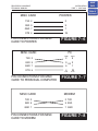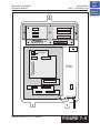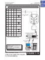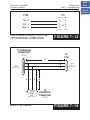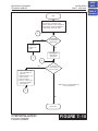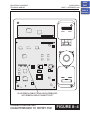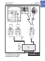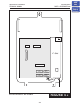
1
PROSTAR DCS COMPACT
TECHNICAL MANUAL
T A B L E
INSTALLATION
TABLE OF CONTENTS JUNE 2001
O F
Table of
Contents
C O N T E N T S
INSTALLATION SECTION
PART
DESCRIPTION
PAGE
1
SITE REQUIREMENTS ................................................................... 1–1
2
INSTALLATION OF BASIC KSU AND EXPANSION KIT
3
4
HOME
PAGE
2.1
UNPACKING AND INSPECTION .................................................. 2–1
2.2
KEY SERVICE UNIT INSTALLATION ............................................ 2–1
2.3
EXPANSION KIT INSTALLATION .................................................. 2–1
2.4
GROUNDING ............................................................................... 2–2
2.5
MDF CABLING ............................................................................. 2–4
INSTALLING PRINTED CIRCUIT CARDS
3.1
RAM PACK .................................................................................... 3–1
3.2
4 CO PROTECTION CARD ........................................................... 3–1
3.3
2 SLI CARD ................................................................................... 3–1
3.4
MISC 1 CARD ............................................................................... 3–1
3.5
MISC 2 CARD ............................................................................... 3–1
3.6
2 X 4 DLI CARD ............................................................................ 3–2
3.7
2 X 4 SLI CARD ............................................................................ 3–2
3.8
2 E&M 4 DLI CARD ...................................................................... 3–2
POWER UP PROCEDURES
4.1
CONNECT POWER TO THE SYSTEM ......................................... 4–1
4.2
RAM CARD INDICATIONS ............................................................ 4–1
4.3
PCB VERIFICATION ..................................................................... 4–1
4.4
DEFAULT TRUNK AND STATION NUMBERING ........................... 4–2
PROSTAR DCS COMPACT
TECHNICAL MANUAL
5
6
INSTALLATION
TABLE OF CONTENTS JANUARY 2002
CONNECTING TELCO CIRCUITS
5.1
SAFETY PRECAUTIONS .............................................................. 5–1
5.2
LOOP START LINES ..................................................................... 5–1
5.3
OFF PREMISE EXTENSIONS (OPX) ............................................ 5–1
5.4
E&M TIE LINES ............................................................................ 5–1
CONNECTING STATION EQUIPMENT
6.1
SAFETY PRECAUTIONS .............................................................. 6–1
6.2
DCS COMPACT KEYSET .............................................................. 6–1
6.3
ADD-ON MODULE ........................................................................ 6–1
6.4
SINGLE LINE TELEPHONE ......................................................... 6–1
6.5
DOOR PHONE AND DOOR LOCK RELEASE............................... 6–1
6.6A
WALL-MOUNTING KEYSETS ....................................................... 6–2
6.6B WALL-MOUNTING KEYSETS WITH ULTRA BASE WEDGE ......... 6–2
6.6C WALL-MOUNTING iDCS KEYSETS .............................................. 6–2
6.7
7
8
ATTACHING DCS 32 BUTTON AOM TO MASTER STATION ........ 6–3
CONNECTING OPTIONAL EQUIPMENT
7.1
MUSIC ON HOLD/BACKGROUND MUSIC ................................... 7–1
7.2
EXTERNAL PAGING ..................................................................... 7–1
7.3
COMMON BELL ........................................................................... 7–1
7.4
RING OVER PAGE ........................................................................ 7–2
7.5
STATION MESSAGE DETAIL RECORDING (SMDR)..................... 7–2
7.6
PC PROGRAMMING..................................................................... 7–2
7.7
REMOTE PROGRAMMING........................................................... 7–3
7.8
POWER FAILURE TRANSFER (PFT) ............................................ 7–3
7.9
VOICE MAIL/AUTO ATTENDANT ................................................. 7–3
7.10
COMPUTER TELEPHONY MODULE (CTM) ................................. 7–3
INSTALLING KEYSET DAUGHTERBOARDS
8.1
KDB DLI ........................................................................................ 8–1
8.2
KBD SLI ........................................................................................ 8–1
8.3
CONNECTING TO THE KDBS...................................................... 8–1
HOME
PAGE
Table of
Contents
PROSTAR DCS COMPACT
TECHNICAL MANUAL
9
10
11
12
13
INSTALLATION
TABLE OF CONTENTS JUNE 2001
CHANGING SOFTWARE
9.1
ACCESSING THE EPROMS ......................................................... 9–1
9.2
REPLACING THE EPROMS ......................................................... 9–1
INSTALLING CALLER ID
10.1
GENERAL INFORMATION ......................................................... 10–1
10.2
INSTALLING ON A NEW SYSTEM ............................................. 10–2
10.3
INSTALLING ON A SYSTEM WITH A MISC 1 CARD .................. 10–2
10.4
INSTALLING ON A SYSTEM WITHOUT A MISC CARD .............. 10–3
ADDING CARDS TO AN EXISTING SYSTEM
11.1
ADDING A MISC CARD .............................................................. 11–1
11.2
ADDING A 2 SLI CARD ............................................................... 11–1
11.3
ADDING A 2 X 4 CARD ............................................................... 11–1
UPGRADING A SYSTEM TO RELEASE 2
12.1
INSTALLING ON A SYSTEM WITH A MISC CARD ..................... 12–1
12.2
INSTALLING ON A SYSTEM WITHOUT A MISC CARD .............. 12–1
INSTALLING A SVMi-4 CARD
13.1
SYSTEM SIZE WITH A SVMi-4 INSTALLED................................ 13–1
13.2
UPGRADING THE SVMi-4 TO FOUR PORTS ............................. 13–1
HOME
PAGE
Table of
Contents
PROSTAR DCS COMPACT
TECHNICAL MANUAL
INSTALLATION
PART 1 DECEMBER 1994
Table of
Contents
PART 1. SITE REQUIREMENTS
When planning the installation of the DCS COMPACT, choose a site that meets the
following requirements:
z
z
z
z
z
z
z
z
Select a location for the key service unit (KSU) that has enough space for easy
installation and adequate lighting (see Figure 1–1).
Select a location that will minimize cable lengths. See the Cable Requirements table
below.
The equipment should not be exposed to direct sunlight, corrosive fumes, dust,
constant vibration or strong magnetic fields such as those generated by motors and
copy machines.
A direct commercial AC power outlet is required. Do not use extension cords.
Preferably, a dedicated circuit should be used to minimize the risk of other electrical
equipment being connected that could adversely affect system operation.
Ensure that all wires and cable going to and coming from the KSU are properly
routed. Do not cross fluorescent lights or run parallel with AC wires.
The equipment must be located in an environment that will maintain a temperature
range of 32°–104°F (0°–40°C) and a humidity range of 10%–90% non-condensing.
Allow at least 6" clearance on both sides and 6" clearance on top of the KSU to
ensure proper ventilation.
Do not install in close proximity to a fire sprinkler head or other sources of water.
Meeting these requirements will help to ensure proper performance and greater life
expectancy of the system.
CABLE REQUIREMENTS
EQUIPMENT
CABLE
AWG
MAX FEET
MAX METERS
DIGITAL KEYSETS
1 PR. TWISTED
24
1300
400
ADD-ON MODULES
1 PR. TWISTED
24
1300
400
SINGLE LINE STATION
1 PR. TWISTED
24
3000
1 KM
DOOR PHONE
2 PR. TWISTED
24
330*
100
SIM
1 PR TWISTED
24
1300
400
*This is the maximum distance a door phone can be from the DPIM. The DPIM can be
a maximum of 900 cable feet from the KSU.
1–1
HOME
PAGE
PROSTAR DCS COMPACT
TECHNICAL MANUAL
INSTALLATION
PART 1 DECEMBER 1994
HOME
PAGE
Table of
Contents
22.5"
5"
14.25"
KEY SERVICE UNIT DIMENSIONS
FIGURE 1– 1
PROSTAR DCS COMPACT
TECHNICAL MANUAL
INSTALLATION
PART 2 JUNE 1995
PART 2. INSTALLATION OF BASIC KSU AND
EXPANSION KIT
2.1 UNPACKING AND INSPECTION
After unpacking the KSU, inspect for signs of physical damage. If any damage is
detected, do not attempt to install. Contact Samsung Telecommunications America,
Technical Support Department.
Check to see that the KSU carton includes the following items:
z
z
z
Key Service Unit
4 Central Office Protection (4 COP) card
Wall-mount kit consisting of three screws
Check to see that the EXPANSION KIT carton includes the following:
z
z
z
Expansion backplane
Plastic card rack
Vinyl bag with screws and cables
2.2 KEY SERVICE UNIT INSTALLATION
The Key Service Unit (KSU) must be wall-mounted. The KSU should be mounted on a
plywood backboard at least 5/8" thick. Attach a mounting screw to the backboard. Next
hang the KSU on the screw and secure it to the backboard with the remaining two
screws (see Figure 2–1).
2.3 EXPANSION KIT INSTALLATION
1. Mount the expansion backplane in the basic KSU and attach it securely with the five
screws supplied. Take care not to over-tighten the screws and damage the PCB
(see Figure 2–2).
2. Connect the expansion backplane to the basic KSU by plugging one end of the
ribbon cable into the socket on the KSU motherboard and the other end into the
expansion backplane.
NOTE: It is recommended that the ribbon cable be attached to the expansion
baseboard before it is installed in the KSU.
3. Connect the ground wires from the expansion backplane to the connectors on the
KSU motherboard.
4. Fit the plastic card rack to the basic KSU and secure with the three screws that are
supplied. Take care not to over-tighten the screws and strip the threads (see Figure
2–3).
2–1
HOME
PAGE
Table of
Contents
PROSTAR DCS COMPACT
TECHNICAL MANUAL
INSTALLATION
PART 2 JUNE 1995
HOME
PAGE
Table of
Contents
2.4 GROUNDING
In order to comply with the revised UL 1459 Telephone Equipment document, the
following paragraphs must be incorporated into this installation manual.
“UL 1459 Paragraph 66. To be included in Installation Instructions.
“66.1.A An equipment grounding conductor that is not smaller in size than the
ungrounded branch-circuit supply conductors is to be installed as part of the circuit
that supplies the product or system. Bare, covered, or insulated grounding conductors
are acceptable. Individually covered or insulated equipment grounding conductors
shall have a continuous outer finish that is either green, green with one or more yellow
stripes. The equipment grounding conductor is to be connected to ground at the
service equipment.
“66.1.B The attachment-plug receptacles in the vicinity of the product or system are all
to be of a grounding type, and the equipment grounding conductors serving these
receptacles are to be connected to earth ground at the service equipment.
“Paragraph 66.1 revised December 13, 1991.”
WARNING: HIGH LEAKAGE CURRENT
Earth Connection Essential Before Connecting Supply
The DCS COMPACT system requires a supplementary (see below) earth ground to be
connected to the KSU in addition to the third wire ground. The grounding lug on the
bottom of the KSU must be connected to a ground rod, bonded building steel or cold
water pipe using at least #16 AWG copper wire (see Figure 2–4). The third wire ground
should not be removed as previously stated in early release manuals.
The following is a definition of a supplementary ground as defined by UL 1459
Telephone Equipment.
“Paragraph 66. To be included in the Installation Instructions.
“66.2.A A supplementary equipment grounding conductor shall be installed between
the product or system and ground that is in addition to the equipment grounding
conductor in the power supply cord.
“66.2.B The supplementary equipment grounding conductor shall not be smaller in size
than the ungrounded branch-circuit supply conductors. The supplementary equipment
grounding conductor shall be connected to the product at the terminal provided, and
shall be connected to ground in a manner that will retain the ground connection when
the product is unplugged from the receptacle. The connection to ground of the
2–2
PROSTAR DCS COMPACT
TECHNICAL MANUAL
INSTALLATION
PART 2 JUNE 1995
supplementary equipment grounding conductor shall be in compliance with the rules
for terminating bonding jumpers in Part K of Article 250 of the National Electrical Code
ANSI/NFPA 70. Termination of the supplementary equipment grounding conductor is
permitted to be made to building steel, to a metal electrical raceway system, or to any
grounded item that is permanently and reliably connected to the electrical service
equipment ground.
“66.2.C Bare, covered, or insulated grounding conductors are acceptable. A covered or
insulated grounding conductor shall have a continuous outer finish that is either green,
or green with one or more yellow stripes.
“Paragraph 66.2 revised September 20, 1993.”
Failure to provide an adequate ground may cause a safety hazard, confusing trouble
symptoms or even circuit card failure.
WARNING: Unplug the power cord from the AC outlet before attempting to connect
the ground. Hazardous voltage may cause death or injury. Observe extreme caution
when working with AC power.
What the above paragraphs mean is when conventional, analog telephone circuits are
connected to the DCS COMPACT system, under fault conditions (e.g., the tip and/or
ring conductor is crossed with a power line, the circuit is affected by lightning during a
storm), it is possible for hazardous potentials to appear across the tip and ring wiring
coming into the DCS COMPACT cabinet from the outside plant (e.g., overhead cables,
buried cables, cable head pedestal). These circuits are provided with both primary and
secondary protection circuitry which will attempt to drain off these high voltages and
currents to earth ground. Obviously, it is important to have a good source of ground
connected to the DCS COMPACT system to which to drain this energy off. Also, certain
metallic analog circuits (e.g., E & M trunks) require a current flow to earth ground to
accommodate normal operating conditions and/or to resolve fault conditions. Again, a
good earth ground source is required by the DCS COMPACT system.
The DCS COMPACT system is grounded in two ways. One way is via the green wire in
the power cord connected to the AC power outlet. However, this can be disconnected
either intentionally or unintentionally. Consequently, a second or supplementary more
permanent ground connection is provided by connecting a high current/voltage
capacity ground wire which is bonded to ground at the electric service power entrance
or via some other method approved by the National Electrical Code to the DCS
COMPACT system ground lug. This is a more secure ground connection which can
only be disconnected intentionally. These precautions are basically taken for safety
reasons to protect personnel working on the DCS COMPACT system and also for
operational reasons to accommodate ground return and/or ground referenced analog
telephone circuits which require this solid earth ground connection for normal
functioning.
2–3
HOME
PAGE
Table of
Contents
PROSTAR DCS COMPACT
TECHNICAL MANUAL
INSTALLATION
PART 2 JUNE 1995
HOME
PAGE
Table of
Contents
2.5 MDF CABLING
All connections to the DCS COMPACT system are made by way of a customerprovided main distribution frame (MDF). The KSU and expansion kit are each
connected to the MDF using a 25 pair female amphenol-type cable. These cables can
be routed into the KSU cabinet from below.
Label each cable to correspond with the connector numbers (see Figure 2–4). Label
each 66 terminating block with the same connector number with which the cable is
labeled.
Use one pair twisted jumper wire to cross-connect stations or lines to their associated
port.
2–4
PROSTAR DCS COMPACT
TECHNICAL MANUAL
INSTALLATION
PART 2 DECEMBER 1994
HOME
PAGE
Table of
Contents
UPPER MOUNTING HOLE
POWER
ON
OFF
_
0
LOWER
MOUNTING HOLES
KSU MOUNTING HOLES
FIGURE 2– 1
PROSTAR DCS COMPACT
TECHNICAL MANUAL
INSTALLATION
PART 2 FEBRUARY 1996
HOME
PAGE
Table of
Contents
SCR5
SCR1
BACKPLANE
MOUNTING SCREWS
P2
SCR2
SCR3
LOCATION OF BACKPLANE
MOUNTING SCREWS
SCR4
FIGURE 2– 2
RACK
MOUNTING SCREWS
SCR5
SCR1
P2
SCR2
SCR3
LOCATION OF RACK MOUNTING
SCREWS
SCR4
FIGURE 2– 3
PROSTAR DCS COMPACT
TECHNICAL MANUAL
INSTALLATION
PART 2 DECEMBER 1994
HOME
PAGE
Table of
Contents
SCR1
SCR5
EXPANSION SLOT 3
EXPANSION SLOT 2
EXPANSION SLOT 1
P2
SCR2
SCR3
SCR4
4 COP SLOT
PSU
RAM PACK SLOT
2 SLI SLOT
MISC SLOT
GROUND LUG
THIRD WIRE
GROUND
KEY SERVICE UNIT GROUNDING
TO POWER
OUTLET
FIGURE 2– 4
PROSTAR DCS COMPACT
TECHNICAL MANUAL
INSTALLATION
PART 3 DECEMBER 1994
PART 3. INSTALLING PRINTED CIRCUIT CARDS
Unpack and inspect each card before installing. Check for signs of physical damage. If
any damage is detected, do not attempt to install. Contact Samsung Technical Support
immediately.
3.1 RAM PACK (Figure 3– 2)
Select the appropriate type of RAM pack for the system. Most systems can utilize a
RAM-1 card; however, systems with Caller ID and those wanting 1500 speed dial
numbers require the RAM-2 card. Make sure that the BACK UP switch is in the OFF
position. Insert the RAM card in the KSU slot labeled RAM (see Figure 3–1). Push firmly
in the middle of the RAM pack to ensure that it is fully inserted into the backplane
connector.
To prevent accidental damage to the RAM card, the RAM connector on the backplane
is positioned to mate only with the RAM card. Other interface cards will not mate with
this connector and the RAM card will not mate with any other connector.
3.2 4 CO PROTECTION CARD (Figure 3– 3)
This card has no selectable options. Insert the 4 CO protection card into the
appropriate slot (see Figure 3–1). Push firmly in the middle of both card ejectors to
ensure that it is fully inserted into the back plane connector.
3.3 2 SLI CARD (Figure 3– 4)
This card has no selectable options. Insert the 2 SLI card into the appropriate slot (see
Figure 3–1). Push firmly in the middle of both card ejectors to ensure that it is fully
inserted into the back plane connector
3.4 MISC 1 CARD (Figure 3– 5)
There are no options to select on this card. Insert the MISC card into the appropriate
slot. Push firmly in the middle of both card ejectors to ensure that it is fully inserted into
the back plane connector.
NOTE: Only one MISC card can be installed in a system.
3.5 MISC 2 CARD (Figure 3– 5)
There are no options to select on this card. Insert the MISC card into the appropriate
slot (see Figure 3–1). Push firmly in the middle of both card ejectors on each card to
ensure that it is fully inserted into the back plane connector.
NOTE: Only one MISC card can be installed in a system.
3–1
HOME
PAGE
Table of
Contents
PROSTAR DCS COMPACT
TECHNICAL MANUAL
INSTALLATION
PART 3 NOVEMBER 1997
Table of
Contents
3.6 2 X 4 DLI CARD (Figure 3– 7)
There are no options to select on this card. Insert the 2 X 4 DLI card into any slot on the
expansion backplane (see Figure 3–6). Push firmly in the middle of both card ejectors
on each card to ensure that it is fully inserted into the back plane connector.
3.7 2 X 4 SLI CARD (Figure 3– 7)
There are no options to select on this card. Insert the 2 X 4 SLI card into any slot on the
expansion backplane (see Figure 3–6). Push firmly in the middle of both card ejectors
on each card to ensure that it is fully inserted into the back plane connector.
3.8 2 E&M 4 DLI CARD (Figure 3– 8)
The E&M trunk circuits on this card can be set to provide either Type 1 or type 5
operation. Type 1 operation is used when connecting to Telco circuits and type 5 is
used when connecting “back to back” across a private cable. Set the jumpers located
between the two relays (see Figure 3–8) according to the table below. Both of the
jumpers for each circuit must be set to the same type for correct operation.
CIRCUIT
JUMPER
POSITION
TYPE
1
J1
T1
TYPE 1
1
J1
T5
TYPE 5
1
J2
T1
TYPE 1
1
J2
T5
TYPE 5
2
J3
T1
TYPE 1
2
J3
T5
TYPE 5
2
J4
T1
TYPE 1
2
J4
T5
TYPE 5
WARNING: Turn the system off and remove the card from the system before
attempting to change jumper settings. 48 volts is present on the jumpers at all times
the system is turned on.
NOTE: When set to TYPE 1 the E&M Tie line circuits on this card are USOC TYPE
TL11M.
3–2
HOME
PAGE
PROSTAR DCS COMPACT
TECHNICAL MANUAL
INSTALLATION
PART 3 DECEMBER 1994
HOME
PAGE
Table of
Contents
4 COP SLOT
PSU
RAM PACK SLOT
2 SLI SLOT
MISC SLOT
408 KSU SLOT POSITIONS
FIGURE 3– 1
PROSTAR DCS COMPACT
TECHNICAL MANUAL
INSTALLATION
PART 3 DECEMBER 1994
HOME
PAGE
Table of
Contents
RE
SE
T
B
OFACK
UP
F
ON
RU UP
N
DCS COMPACT RAM PACK
FIGURE 3– 2
PROSTAR DCS COMPACT
TECHNICAL MANUAL
INSTALLATION
PART 3 DECEMBER 1994
HOME
PAGE
Table of
Contents
4TRK
R405
R305
C402
D402
D404
R205
C302
D304
D204
D302
R105
C202
C102
D401
D104
D202
D301
D201
D101
U301
U201
U101
D102
U403 U402
U303 U302
D403
C404 C407
U203 U202
D303
C304 C307
RLY8
C204 C207
RLY7
T3
C201
RLY3
DSS2
DSS7
DSS5
DSS3
DSS1
C101
RLY2
RLY1
C1
BAR CODE
P4
4 CO PROTECTION CARD
RW3
BAR CODE
P3
FIGURE 3– 3
DCS COMPACT (2SLC)
C104
C312
C311
DSS4
T1
T2
RLY4
DSS6
RLY5
C301
T4
D103
DSS8
C104 C107
RLY6
C401
U401
U103 U102
D203
RW2
HYB2
RW1
RLY2
HYB1
RLY1
T1
U101
U102
C310
C102 C101
C202 C201
T2
T301
C103
C203
C116
C308
DSSV4
U202
U201
U302
C314
R319
C301
2 SLI CARD
DSSV3
DSSV2
DSSV1
C113 C5
C314
C3
P5
FIGURE 3– 4
PROSTAR DCS COMPACT
TECHNICAL MANUAL
INSTALLATION
PART 3 DECEMBER 1994
HOME
PAGE
Table of
Contents
PORT 2
TNR1
P7
U6
C10
BAR CODE
U5
Y2
C12
U4
U7
T1
C14
C15
C17
U1
Y1
TNR4
U8
TNR3
TNR2
U3
U2
P1
P2
PORT 1
DCS COMPACT (MISC)
MISC CARD
FIGURE 3– 5
PROSTAR DCS COMPACT
TECHNICAL MANUAL
INSTALLATION
PART 3 DECEMBER 1994
HOME
PAGE
Table of
Contents
SCR1
SCR5
EXPANSION SLOT 3
EXPANSION SLOT 2
EXPANSION SLOT 1
P2
SCR2
SCR3
SCR4
4 COP SLOT
PSU
RAM PACK SLOT
2 SLI SLOT
MISC SLOT
EXPANSION KIT INSTALLED IN KSU
FIGURE 3– 6
2 X 4 DLI CARD AND 2 X 4 SLI CARD
C701
Q701
C710
C714
U702
U1
R700
C700
C3
U2
U3
C1
C5
C3
C5
DCS COMPACT (204SLT)
C708
BAR CODE
R719
T701
C709
C712
C711
BAR CODE
DCS COMPACT (204DLI)
U1
C510
U2
C310
U602
C507
C307
C402 PS1
U502
U402
U302
T1
U4
T2
HYB5
C502 PS2
U5
P1
T3
T6
T5
T4
T3
P1
C602 PS31
U6
C611
C604
C504
C511
C411
C702 PS4
C304
C404
C311
T4
U7
R603
R503
R403
R303
C202
RL4
T6
C601
HYB4
HYB3
HYB2
HYB1
RL3
C501
RL8
C602
RL7
C502
C401 RL6
C402
U201 D201
U204
U101
P2
C201
U201
D202
D203
HYBR
U205
U204
R205
U104
U105
RL3 D204
C202
C116
C203 U202 C205
C113
C101
U203
U102
RL4
T2
T5
T1
U101
RL1
C103
R105
D104 RL1
R105
D103
C101
D101 D102
P2
C103
U103 U102
U105
C105
U104
C113
C116
DSSV4 DSSV3 DSSV2 DSSV1
D202
C201
C301 RL5
C203
U202 U203
D203
C302
D204
R205
C205
U205
C102
C105
D103 D102
D104
U103
RL2
C102
RL2
PROSTAR DCS COMPACT
TECHNICAL MANUAL
INSTALLATION
PART 3 DECEMBER 1994
FIGURE 3– 7
HOME
PAGE
Table of
Contents
BAR CODE
U1
C110
U2
U3
DCS COMPACT (2E&M/4DLI)
T4
PS4 C402
U4
PS5 C502
2 E&M / 4 DLI CARD
J3
FG
NO
48
48
NC
T5
T1
T5
T1
FG
FG
NO
48
48
NC
RLY1
T3
DSS4
C212
DSS3
C289
DSS2
P2
DSS1
RLY2
T3
U23
TYPE
RLY1
R203 R201 R301
U22 U21
J4
TYPE
C112
R303
U33
PS32
C100
PS7 C702
U31 U32
PS31
P1
PS6 C602
T7
U7
PS22
J2
FG
T6
U6
PS21
J1
J3
RLY2
T5
U5
PROSTAR DCS COMPACT
TECHNICAL MANUAL
INSTALLATION
PART 3 NOVEMBER 1997
J1
J2
J4
FIGURE 3– 8
HOME
PAGE
Table of
Contents
PROSTAR DCS COMPACT
TECHNICAL MANUAL
INSTALLATION
PART 4 NOVEMBER 1997
PART 4. POWER UP PROCEDURES
4.1 CONNECT POWER TO THE SYSTEM
During the initial installation, it is best to verify proper system operation before plugging
in any amphenol-type cables to the MDF. If you have already plugged the cables in,
unplug them at this time.
Verify that the AC voltage at the dedicated electrical outlet is in the range of 82–132
Volts AC. Make sure the AC power switch on the system power supply is in the OFF
position and that the RAM pack battery switch is also in the OFF position. Plug the KSU
power cord into the dedicated polarized AC outlet. Turn the AC power switch to the ON
position. The LED on the power supply will light steady to confirm the presence of
power. If the PSU LED fails to illuminate, unplug the system, remove the power supply
and check the AC fuse located on the bottom.
If the fuse is good but the LED does not illuminate, you must correct the problem
before continuing. Turn off the power switch. Unplug all cards using the card ejectors.
Turn the system on. Check the LED again. If the problem is corrected, you have a
defective card. Test and remove the faulty card before continuing. If the LED still does
not light, unplug the KSU and change power supplies. This in all probability will solve
the problem. If it does not, contact Samsung Technical Support.
4.2 RAM CARD INDICATIONS
Having verified proper operation of the power supply, visually check the RAM card
indications. The LED should flicker rapidly indicating the main processor is functioning.
The battery switch should now be turned ON. If the LED remains lit steady turn power
to the system OFF and check the installation of the EPROM’s by removing them and
checking for bent or damaged pins. If the EPROMS appear to be installed correctly
and the system does not come up when turned on, Contact Samsung Technical
support.
The system is equipped with a halt program. When this program is running, the LED is
ON steady. The system must be reset to release the halt program and restore the
system to normal operation. See MMC 810 for operation of the halt program.
4.3 PCB VERIFICATION
Before connecting all MDF cabling, plug in a test cable to the first DLI port. Connect a
display set and verify that it is working. Use maintenance program MMC 805 (or MMC
727 for Release 2 systems) to verify the system version, software version and that all
cards are recognized by the CPU. Remove the test cable and plug in all amphenol-type
cables to the MDF. Proceed with the rest of the installation.
4–1
HOME
PAGE
Table of
Contents
PROSTAR DCS COMPACT
TECHNICAL MANUAL
INSTALLATION
PART 4 NOVEMBER 1997
4.4 DEFAULT TRUNK AND STATION NUMBERING
Upon initial power up, the CPU reads each slot for the existence of a card and identifies
the type of card. It stores this as the default configuration.
The system assigns trunk numbers beginning with 701 and continues to 704 for a basic
KSU or to 710 for a fully equipped KSU.
Station numbers are assigned in the same manner. The lowest station is assigned
station number 201 and continues to 208 for a basic KSU or to 222 for a fully equipped
KSU. Keyset daughterboards are assigned numbers beginning with 301 and continue
to 310. Default data assigns the keyset in the lowest port to the operator group and all
trunks ring that station until the default is changed.
Station and trunk numbers can be changed, rearranged and reassigned as needed
using MMC 724.
4–2
HOME
PAGE
Table of
Contents
PROSTAR DCS COMPACT
TECHNICAL MANUAL
INSTALLATION
PART 5 NOVEMBER 1997
PART 5. CONNECTING TELCO CIRCUITS
5.1 SAFETY PRECAUTIONS
To limit the risk of personal injury, always follow these precautions before connecting
TELCO circuits:
a. Never install telephone wiring during a lightning storm.
b. Never install telephone jacks in a wet location unless the jack is specifically
designed for wet locations.
c. Never touch uninsulated telephone wires or terminals unless the telephone line has
been disconnected at the network interface.
d. Use caution when installing or modifying telephone lines.
5.2 LOOP START LINES
Using one pair twisted #24 AWG or #26 AWG jumper wire, cross-connect each loop
start C.O. line to the trunk port of your choice (see Figures 5–1 and 5–2).
5.3 OFF PREMISE EXTENSIONS (OPX)
Using one pair twisted #24 AWG or #26 AWG jumper wire, cross-connect any 2 SLI
port to telephone company OPX circuits (see Figure 5–3).
Circuits on the 2 SLI card are specifically designed to meet TELCO requirements for
OPX use. These circuits are provided with the same over voltage and over current
protection as C.O. line circuits. Using single line stations on a 2 X 4 SLI or KDb SLI may
cause damage to your equipment.
There is no special programming required for OPX use; however, it is suggested that
the OPX ports be set programmed as “data ring” in MMC 208 to provide a disconnect
signal to the OPX equipment. The telephone company service facility interface code for
this type of OPX circuit is OL13C.
5.4 E&M TIE LINES
Using two pair twisted #24 AWG or #26 AWG jumper wire, cross-connect any E&M
circuit to a telephone company E&M circuit (see Figure 5–4). The telephone company
service facility interface code for the E&M tie line is TL11M. This is a 2 wire Type 1 tie
line.
NOTE: When connecting an E&M tie line in “back to back” fashion you must remember
to reverse the E&M leads at one end ONLY. i.e. connect the E lead on one system to
the M lead of the other system and vice versa.
5–1
HOME
PAGE
Table of
Contents
PROSTAR DCS COMPACT
TECHNICAL MANUAL
INSTALLATION
PART 5 DECEMBER 1994
Table of
Contents
25 PAIR CABLE WITH FEMALE CONNECTOR TO KSU P1
FUNCTION
CIRCUIT
C.O. TIP
1
C.O. RING
C.O. TIP
TERM
COLOR
PIN
1
W-BL
26
2
BL-W
1
3
W-O
27
4
O-W
2
5
W-GN
28
6
GN-W
3
7
W-BR
29
8
BR-W
4
2
C.O. RING
TELCO-PROVIDED
NETWORK ACCESS JACK
RJ 11C
RJ 14C
RJ 21X
CONNECT TO ANY CO CIRCUIT
ON THE BASIC KSU.
C.O. TIP
3
C.O. RING
C.O. TIP
4
C.O. RING
NOTE: ONLY LOOP START LINES CAN BE
CONNECTED TO A DCS COMPACT.
MDF CONNECTIONS
LOOP START LINE TO BASIC KSU
HOME
PAGE
FIGURE 5– 1
PROSTAR DCS COMPACT
TECHNICAL MANUAL
INSTALLATION
PART 5 NOVEMBER 1997
Table of
Contents
25 PAIR CABLE WITH FEMALE CONNECTOR TO EXPANSION KIT P2
FUNCTION
CIRCUIT
TERM
COLOR
PIN
1
W-BL
26
2
BL-W
1
3
W-O
27
4
O-W
2
C.O. TIP
5
W-GN
28
C.O. RING
6
GN-W
3
7
W-BR
29
8
BR-W
4
9
W-S
30
10
S-W
5
11
R-BL
31
12
BL-R
6
13
R-O
32
14
O-R
7
15
R-GR
33
16
GR-R
8
17
R-BR
34
18
BR-R
9
19
R-S
35
20
S-R
10
21
BK-BL
36
22
BL-BK
11
23
BK-O
37
24
O-BK
12
C.O. TIP
C.O. RING
5
6
TELCO PROVIDED
NETWORK ACCESS JACK
RJ 11C
RJ 14C
RJ 21X
C.O. TIP
C.O. RING
7
C.O. TIP
C.O. RING
8
C.O. TIP
C.O. RING
9
C.O. TIP
C.O. RING
10
CONNECT TO ANY C.O. CIRCUIT
FROM ANY 2 X 4 DLI OR 2 X 4 SLI CARD
MDF CONNECTIONS
LOOP START LINE TO EXPANSION CARD
HOME
PAGE
FIGURE 5– 2
PROSTAR DCS COMPACT
TECHNICAL MANUAL
INSTALLATION
PART 5 DECEMBER 1994
HOME
PAGE
Table of
Contents
25 PAIR CABLE WITH FEMALE CONNECTOR TO KSU P1
FUNCTION
CIRCUIT
SLT TIP
TERM
COLOR
PIN
29
BK-SL
40
30
SL-BK
15
31
Y-BL
41
32
BL-Y
16
1
SLT RING
SLT TIP
2
SLT RING
TELCO-PROVIDED
NETWORK ACCESS JACK
RJ 11C
RJ 14C
RJ 21X
CONNECT TO ANY CIRCUIT ON
THE 2 SLI CARD.
MDF CONNECTIONS
OFF PREMISE EXTENSION FROM
2 SLI CARD
FIGURE 5– 3
PROSTAR DCS COMPACT
TECHNICAL MANUAL
INSTALLATION
PART 5 NOVEMBER 1997
Table of
Contents
25 PAIR CABLE WITH FEMALE CONNECTOR TO EXPANSION KIT P2
FUNCTION
CIRCUIT
TERM
COLOR
PIN
1
W-BL
26
2
BL-W
1
E
3
W-O
27
M
4
O-W
2
C.O. TIP
5
W-GN
28
C.O. RING
6
GN-W
3
E
7
W-BR
29
M
8
BR-W
4
9
W-S
30
10
S-W
5
11
R-BL
31
12
BL-R
6
13
R-O
32
14
O-R
7
15
R-GR
33
16
GR-R
8
17
R-BR
34
18
BR-R
9
19
R-S
35
20
S-R
10
21
BK-BL
36
22
BL-BK
11
23
BK-O
37
24
O-BK
12
C.O. TIP
C.O. RING
TELCO PROVIDED
NETWORK ACCESS JACK
RJ 2GX
5
6
C.O. TIP
C.O. RING
7
C.O. TIP
C.O. RING
8
C.O. TIP
C.O. RING
9
C.O. TIP
C.O. RING
10
CONNECT TO ANY E&M CIRCUIT
FROM ANY 2 E&M 4DLI.
MDF CONNECTIONS
E&M LINE TO EXPANSION CARD
HOME
PAGE
FIGURE 5– 4
PROSTAR DCS COMPACT
TECHNICAL MANUAL
INSTALLATION
PART 6 JANUARY 2002
PART 6. CONNECTING STATION EQUIPMENT
6.1 SAFETY PRECAUTIONS
To limit the risk of personal injury, always follow these precautions before connecting
telephone circuits:
a. Never install telephone wiring during a lightning storm.
b. Never install telephone jacks in a wet location unless the jack is specifically
designed for wet locations.
c. Never touch uninsulated telephone wires or terminals unless the telephone line has
been disconnected at the network interface.
d. Use caution when installing or modifying telephone lines.
6.2 KEYSETS
Using one pair twisted #24 AWG or #26 AWG jumper wire, cross-connect each keyset
to the DLI port of your choice (see Figures 6–1 and 6–2).
NOTE: Because the DCS COMPACT is a self-configuring system, if you connect a 12
button keyset to a DLI port that previously had a 24 button keyset installed, the existing
data will be rewritten with 12 button keyset default data (see MMC 723).
6.3 DCS 32 BUTTON ADD-ON MODULE
Using one pair twisted #24 AWG or #26 AWG jumper wire, cross-connect each DCS
32 Button Add-On Module (AOM) to the DLI port of your choice (see Figures 6–3 and
6–4).
If an AOM is to operate as a stand-alone unit, there is nothing else required other than
assigning keys. When an AOM is to be used with a station, it must be assigned in MMC
209. Add-on modules can be assigned to any keyset.
6.4 SINGLE LINE TELEPHONE
Using one pair twisted #24 AWG or #26 AWG jumper wire, cross-connect each single
line telephone to the SLI port of your choice (see Figures 6–5 and 6–6).
6.5 DOOR PHONE AND DOOR LOCK RELEASE
Using one pair twisted #24 AWG or #26 AWG jumper wire, cross-connect each DPIM
to the DLI port of your choice (see Figures 6–7 and 6–8). Next, connect the DPIM to the
door phone using #24 AWG or #26 AWG twisted pair wire.
6–1
HOME
PAGE
Table of
Contents
PROSTAR DCS COMPACT
TECHNICAL MANUAL
INSTALLATION
PART 6 JANUARY 2002
When a customer-provided electric door release is installed, cross-connect the
corresponding door release contacts on the DPIM to the door lock mechanism (see
Figures 6–7 and 6–8). Use MMC 501 to program the duration of the contact closure as
required. See the user guides for door lock release operation. The door release
contacts on the DPIM are to be used for low voltage relay control only. The contacts
are rated at 24 VDC-1 amp.
WARNING: Do not attempt to connect commercial AC power to these contacts.
6.6A WALL-MOUNTING KEYSETS
DCS keysets come equipped with a reversible base wedge. To wall-mount a keyset,
remove the wedge from the keyset and remove the directory tray from the wedge.
Mount the wedge to the wall using one of the methods below (see Figure 6–9).
Use screw holes 1 and 2 to attach the base wedge to a standard electrical outlet box.
OR
Use screw holes 1 and 3 to attach to a standard telephone wall-mount plate with
locking pins. This method can cause the keyset to wobble as the keyset feet do not fit
securely to the mounting surface.
OR
Use screw holes 4 and 5 if you are mounting on dry wall with a hole in the middle for
cable access.
6.6B WALL-MOUNTING KEYSETS WITH ULTRA BASE
WEDGE
DCS keysets now come equipped with a new Ultra Base wedge. These base wedges
are reversible and can be used for wall-mounting, however not every wall mounting
scenario is appropriate. First and foremost there is only one keyhole in the center of the
base attaching the wall, and these base wedges can not be used with the standard wall
mount bracket with the two buttons/pins. To wall-mount the keyset using Ultra Base
wedges use screw holes 1, 2 and 3 to mount the base wedge on dry wall with the hole
in the middle for cable access (see Figure 6–10).
6.6C WALL-MOUNTING iDCS KEYSETS
iDCS keysets come equipped with a reversible base wedge. To wall-mount a keyset,
remove the wedge from the keyset and mount the wedge to the wall using one of the
methods below (see Figure 6–11).
6–2
HOME
PAGE
Table of
Contents
PROSTAR DCS COMPACT
TECHNICAL MANUAL
INSTALLATION
PART 6 JUNE 2001
Use screw holes 1 and 2 to attach the base wedge to a standard electrical outlet box.
OR
Use screw holes 1 and 3 to attach to a standard telephone wall-mount plate with
locking pins. This method can cause the keyset to wobble as the keyset feet do not fit
securely to the mounting surface.
6.7 ATTACHING DCS 32 BUTTON AOM TO MASTER
STATION
These new Ultra Base Wedges allow a connector clip (packaged with the DCS 32
Button AOM) to be connected to the underside of the new style wedge and attach
AOM(s) together with the main or “master” station. This “clip” allows multiple AOMs to
be secured or “chained” together to the main or “master” station they are associated
with. This will make instruments associated with each other seem as one unit (see
Figure 6–12).
6–3
HOME
PAGE
Table of
Contents
PROSTAR DCS COMPACT
TECHNICAL MANUAL
INSTALLATION
PART 6 DECEMBER 1994
Table of
Contents
25 PAIR CABLE WITH FEMALE CONNECTOR TO KSU P1
PIN
COLOR
TERM
31
R-BL
11
6
BL-R
12
32
R-O
13
7
O-R
14
33
R-GN
15
8
GN-R
16
34
R-BR
17
9
BR-R
18
35
R-S
19
10
S-R
20
36
BK-BL
21
CIRCUIT
FUNCTION
DLI TIP
1
DLI RING
DLI TIP
2
3
DLI RING
DLI TIP
ONE PAIR TWISTED
SHEATHED STATION CABLE
24 OR 26 AWG
R
G
BK
Y
W
BL
DLI RING
4
DLI TIP
DLI RING
5
DLI TIP
DLI RING
DLI TIP
6
11
BL-BK
22
37
BK-O
23
12
O-BK
24
38
BK-GR
25
13
GR-BK
26
1
DLI RING
2
3
4
5
6
DLI TIP
7
DLI RING
DLI TIP
8
DLI RING
DIGITAL KEYSET
SCROLL
VOL
CONNECT TO ANY DLI
ON KSU P1.
CIRCUIT
2 ABC
3 DEF
4 GHI
5 JKL
6 MNO
7 PRS
8 TUV
9 WXY
SPK
HOLD
TRSF
ANS/
RLS
MDF CONNECTIONS
DIGITAL KEYSET TO KSU P1
1
HOME
PAGE
0OPER
FIGURE 6– 1
PROSTAR DCS COMPACT
TECHNICAL MANUAL
INSTALLATION
PART 6 DECEMBER 1994
25 PAIR CABLE WITH FEMALE CONNECTOR TO EXPANSION KIT P2
PIN
COLOR
TERM
39
BK-BR
27
14
BR-BK
28
40
BK-SL
29
CIRCUIT
9
SL-BK
DLI TIP
DLI RING
DLI TIP
10
15
FUNCTION
30
DLI RING
DLI TIP
41
Y-BL
31
16
BL-Y
32
DLI RING
42
Y-O
33
DLI TIP
17
O-Y
34
DLI RING
43
Y-GR
35
DLI TIP
18
GR-Y
36
44
Y-BR
37
19
BR-Y
38
45
Y-SL
39
20
SL-Y
40
46
V-BL
41
11
12
13
BL-V
42
47
V-O
43
22
O-V
44
48
V-GR
45
14
GR-V
46
49
V-BR
47
24
BR-V
48
50
V-SL
49
25
SL-V
50
G
BK
Y
W
BL
DLI TIP
1
DLI RING
2
3
4
5
6
DLI TIP
DLI RING
DLI TIP
16
DLI RING
DLI TIP
17
DLI RING
DLI TIP
18
23
R
DLI RING
15
21
ONE PAIR TWISTED
SHEATHED STATION CABLE
24 OR 26 AWG
DLI RING
DIGITAL KEYSET
DLI TIP
19
20
DLI RING
SCROLL
DLI TIP
DLI RING
VOL
CONNECT TO ANY DLI CIRCUIT ON
A 2 X 4 CARD.
2 ABC
3 DEF
4 GHI
5 JKL
6 MNO
7 PRS
8 TUV
9 WXY
HOLD
TRSF
ANS/
RLS
MDF CONNECTIONS
DIGITAL KEYSET TO EXPANSION CARD
1
SPK
0OPER
FIGURE 6– 2
HOME
PAGE
Table of
Contents
PROSTAR DCS COMPACT
TECHNICAL MANUAL
INSTALLATION
PART 6 DECEMBER 1994
HOME
PAGE
Table of
Contents
25 PAIR CABLE WITH FEMALE CONNECTOR TO KSU P1
PIN
COLOR
TERM
31
R-BL
11
6
BL-R
12
32
R-O
13
CIRCUIT
1
FUNCTION
DLI TIP
DLI RING
DLI TIP
2
DLI RING
7
O-R
14
33
R-GN
15
8
GN-R
16
DLI RING
34
R-BR
17
DLI TIP
9
BR-R
18
35
R-S
19
10
S-R
20
36
BK-BL
21
DLI TIP
3
11
BL-BK
22
37
BK-O
23
12
O-BK
24
38
BK-GR
25
4
GR-BK
26
R
G
BK
Y
W
BL
DLI RING
5
DLI TIP
DLI RING
DLI TIP
6
1
DLI RING
2
3
4
5
6
DLI TIP
7
DLI RING
DLI TIP
8
13
ONE PAIR TWISTED
SHEATHED STATION CABLE
24 OR 26 AWG
DLI RING
ADD-ON MODULE
CONNECT TO ANY DLI
ON KSU P1.
CIRCUIT
VOL
MDF CONNECTIONS
AOM TO KSU P1
MUTE
SPK
FIGURE 6– 3
PROSTAR DCS COMPACT
TECHNICAL MANUAL
INSTALLATION
PART 6 DECEMBER 1994
HOME
PAGE
Table of
Contents
25 PAIR CABLE WITH FEMALE CONNECTOR TO EXPANSION KIT P2
PIN
COLOR
TERM
39
BK-BR
27
14
BR-BK
28
40
BK-SL
29
CIRCUIT
9
FUNCTION
DLI TIP
DLI RING
DLI TIP
10
DLI RING
15
SL-BK
30
41
Y-BL
31
16
BL-Y
32
DLI RING
42
Y-O
33
DLI TIP
17
O-Y
34
43
Y-GR
35
18
GR-Y
36
44
Y-BR
37
19
BR-Y
38
DLI TIP
11
ONE PAIR TWISTED
SHEATHED STATION CABLE
24 OR 26 AWG
R
G
BK
Y
W
BL
12
DLI RING
DLI TIP
13
45
Y-SL
39
20
SL-Y
40
46
V-BL
41
DLI RING
DLI TIP
14
42
47
V-O
43
22
O-V
44
48
V-GR
45
23
GR-V
46
49
V-BR
47
3
4
5
6
DLI RING
DLI TIP
16
BL-V
2
DLI TIP
15
21
1
DLI RING
DLI RING
DLI TIP
17
DLI RING
DLI TIP
18
DLI RING
ADD-ON MODULE
DLI TIP
19
24
BR-V
48
50
V-SL
49
DLI RING
DLI TIP
20
25
SL-V
50
DLI RING
CONNECT TO ANY DLI CIRCUIT ON
A 2 X 4 CARD.
VOL
MDF CONNECTIONS
AOM TO EXPANSION CARD
MUTE
SPK
FIGURE 6– 4
PROSTAR DCS COMPACT
TECHNICAL MANUAL
INSTALLATION
PART 6 DECEMBER 1994
HOME
PAGE
Table of
Contents
25 PAIR CABLE WITH FEMALE CONNECTOR TO KSU P1
PIN
COLOR
40
BK-SL
TERM CIRCUIT
29
FUNCTION
SLT TIP
1
15
SL-BK
30
41
Y-BL
31
16
BL-Y
32
SLT RING
SLT TIP
2
SLT RING
ONE PAIR TWISTED
SHEATHED STATION CABLE
24 OR 26 AWG
R
G
BK
Y
W
BL
1
2
3
4
5
6
CONNECT TO ANY CIRCUIT ON
THE 2 SLI CARD.
SINGLE LINE TELEPHONE
MDF CONNECTIONS
SINGLE LINE TELEPHONE
TO 2 SLI CARD
FIGURE 6– 5
PROSTAR DCS COMPACT
TECHNICAL MANUAL
INSTALLATION
PART 6 DECEMBER 1994
HOME
PAGE
Table of
Contents
25 PAIR CABLE WITH FEMALE CONNECTOR TO EXPANSION KIT P2
PIN
COLOR
TERM
CIRCUIT
39
BK-BR
27
14
BR-BK
28
40
BK-SL
29
15
SL-BK
30
SLI RING
41
Y-BL
31
SLI TIP
16
BL-Y
32
42
Y-O
33
17
O-Y
34
SLI RING
43
Y-GR
35
SLI TIP
18
GR-Y
36
44
Y-BR
37
19
BR-Y
38
45
Y-SL
39
9
SL-Y
40
46
V-BL
41
SLI TIP
SLI RING
10
11
SLI TIP
ONE PAIR TWISTED
SHEATHED STATION CABLE
24 OR 26 AWG
R
G
BK
Y
W
BL
SLI RING
SLI TIP
12
13
20
FUNCTION
14
SLI RING
SLI TIP
1
SLI RING
2
3
4
5
6
SLI TIP
15
SLI RING
SLI TIP
16
21
BL-V
42
47
V-O
43
SLI RING
SLI TIP
17
22
O-V
44
48
V-GR
45
23
GR-V
46
49
V-BR
47
24
BR-V
48
50
V-SL
49
SLI RING
18
SLI TIP
SLI RING
19
SLI TIP
SINGLE LINE
TELEPHONE
SLI RING
SLI TIP
20
25
SL-V
50
SLI RING
CONNECT TO ANY SLI CIRCUIT
ON A 2 X 4 CARD.
MDF CONNECTIONS
SLT TO EXPANSION CARD
FIGURE 6– 6
PROSTAR DCS COMPACT
TECHNICAL MANUAL
INSTALLATION
PART 6 DECEMBER 1994
Table of
Contents
25 PAIR CABLE WITH FEMALE CONNECTOR TO KSU P1
PIN
COLOR
TERM
31
R-BL
11
CIRCUIT
FUNCTION
DLI TIP
1
DLI RING
6
BL-R
12
32
R-O
13
7
O-R
14
33
R-GN
15
8
GN-R
16
DLI RING
34
R-BR
17
DLI TIP
9
BR-R
18
DLI RING
35
R-S
19
DLI TIP
10
S-R
20
36
BK-BL
21
DLI TIP
2
3
4
5
DLI RING
DLI TIP
ONE PAIR TWISTED
SHEATHED STATION CABLE
24 OR 26 AWG
R
G
BK
Y
W
BL
DLI RING
DLI TIP
1
6
11
BL-BK
22
37
BK-O
23
12
O-BK
24
38
BK-GR
25
13
GR-BK
26
DLI RING
2
3
4
5
6
DLI TIP
7
DLI RING
DLI TIP
8
DLI RING
TO CUSTOMER-PROVIDED
DOOR LOCK RELEASE
WHITE
BLUE
LOCK
THREE PAIR
MODULAR CABLE
DOOR BOX
LINE
DOOR PHONE
INTERFACE
MODULE (DPIM)
DOOR PHONE
CONNECT TO ANY DLI CIRCUIT
ON KSU P1.
P+
RED
P-
L1
GREEN
BLACK
MDF CONNECTIONS
DOOR PHONE TO KSU P1
L2
HOME
PAGE
TWO
PAIR
MODULAR
CABLE
YELLOW
FIGURE 6– 7
PROSTAR DCS COMPACT
TECHNICAL MANUAL
INSTALLATION
PART 6 DECEMBER 1994
25 PAIR CABLE WITH FEMALE CONNECTOR TO EXPANSION KIT P2
PIN
COLOR
TERM
39
BK-BR
27
CIRCUIT
FUNCTION
DLI TIP
9
14
BR-BK
28
40
BK-SL
29
15
SL-BK
30
DLI RING
41
Y-BL
31
DLI TIP
16
BL-Y
32
DLI RING
42
Y-O
33
DLI TIP
17
O-Y
34
43
Y-GR
35
18
GR-Y
36
44
Y-BR
37
19
BR-Y
38
DLI RING
45
Y-SL
39
DLI TIP
20
SL-Y
40
46
V-BL
41
21
BL-V
42
47
V-O
43
DLI RING
10
11
DLI TIP
O-V
44
48
V-GR
45
23
GR-V
46
49
V-BR
47
24
BR-V
48
50
V-SL
49
25
SL-V
50
R
G
BK
Y
W
BL
12
DLI RING
13
DLI TIP
DLI RING
DLI TIP
14
15
DLI RING
DLI TIP
16
22
ONE PAIR TWISTED
SHEATHED STATION CABLE
24 OR 26 AWG
DLI RING
1
2
3
4
5
6
TO CUSTOMERPROVIDED
DOOR LOCK
RELEASE
DLI TIP
17
DLI RING
WHITE
BLUE
DLI TIP
18
DLI RING
LOCK
DLI TIP
19
DLI RING
DLI TIP
20
THREE PAIR
MODULAR CABLE
DLI RING
DOOR BOX
LINE
DOOR
PHONE
INTERFACE
MODULE
(DPIM)
DOOR PHONE
CONNECT TO ANY DLI CIRCUIT ON
A 2 X 4 CARD.
P+
P-
L1
L2
GREEN
RED
BLACK
MDF CONNECTIONS
DOOR PHONE TO EXPANSION CARD
TWO
PAIR
MODULAR
CABLE
YELLOW
FIGURE 6– 8
HOME
PAGE
Table of
Contents
PROSTAR DCS COMPACT
TECHNICAL MANUAL
INSTALLATION
PART 6 JUNE 2001
HOME
PAGE
Table of
Contents
1
5
4
2
3
HOLES FOR MOUNTING SCREWS
NOTE: THE DIRECTORY CARD SLIDE TRAY IS NOT USED WHEN THE
KEYSET IS WALL-MOUNTED.
WALL-MOUNTING A KEYSET
FIGURE 6–9
6-7
FIGURE
PROSTAR DCS COMPACT
TECHNICAL MANUAL
INSTALLATION
PART 6 JUNE 2001
HOME
PAGE
Table of
Contents
1
2
3
USED FOR ATTACHING
AOMS WITH
CONNECTOR CLIP
HOLES FOR MOUNTING SCREWS
NOTE: THE DIRECTORY CARD SLIDE TRAY IS NOT USED WHEN THE
KEYSET IS WALL-MOUNTED.
ULTRA BASE WEDGE
FIGURE6–10
6-7
FIGURE
PROSTAR DCS COMPACT
TECHNICAL MANUAL
INSTALLATION
PART 6 JANUARY 2002
HOME
PAGE
Table of
Contents
1
2
3
WALL-MOUNTING
AN iDCS KEYSET
FIGURE6–11
6 -7
FIGURE
PROSTAR DCS COMPACT
TECHNICAL MANUAL
INSTALLATION
PART 6 JUNE 2001
HOME
PAGE
GROOVE FOR
ADDITIONAL
CONNECTOR
CLIP
METAL
CONNECTOR
CLIP
24B / 12B ULTRA BASE WEDGE
AOM ULTRA BASE WEDGE
Table of
Contents
ATTACHING 24B/12B TO AOM
FIGURE6–12
6 -7
FIGURE
PROSTAR DCS COMPACT
TECHNICAL MANUAL
INSTALLATION
PART 7 DECEMBER 1994
PART 7. CONNECTING OPTIONAL EQUIPMENT
7.1 MUSIC ON HOLD/BACKGROUND MUSIC
Connect each customer-provided music source to the music input on the KSU
connecting block (see Figure 7–1). The music input has internal automatic gain
compensation features.
IMPORTANT NOTICE: In accordance with US Copyright Law, a license may be
required from the American Society of Composers, Authors and Publishers (ASCAP) or
another similar organization if copyrighted music is transmitted through the Music on
Hold feature. Samsung Telecommunications America, Inc. hereby disclaims any
liability arising out of failure to obtain such a license.
Each C.O. line (trunk) can be programmed to receive a music source, system
generated TONE or NO MUSIC when it is put on hold. See MMC 408. Each keyset can
receive a music source or NO MUSIC for background music. See programming manual
for instructions (see MMC 308).
7.2 EXTERNAL PAGING
The KSU provides a voice pair to be used with customer-provided paging equipment.
Connect the customer provided paging equipment to the page output pins of the KSU
connecting block (see Figure 7–2). The page voice pair is 600 ohm impedance. When
the amplifier page input is not 600 ohm, a suitable impedance matching transformer
must be used.
If installed, the MISC card provides four zone control relays (see Figure 7–3). These
paging contact pairs are for control of low voltage circuits or amplifier output. The
contacts are rated at 24 VDC-1 amp.
WARNING: Do not attempt to connect commercial AC power to these contacts.
7.3 COMMON BELL
A customer-provided loud ringing device can be controlled using the dry contact pair
on the KSU. See Figure 7–4.
Programming allows for INTERRUPTED or CONTINUOUS operation of the contacts
using MMC 204. The interrupted selection follows the C.O. ring cadence—one second
ON/three seconds OFF.
After connecting a common bell, you must assign it to a group in MMC 601 as a ring
destination by using the code for Common Bell.
7–1
HOME
PAGE
Table of
Contents
PROSTAR DCS COMPACT
TECHNICAL MANUAL
INSTALLATION
PART 7 DECEMBER 1994
The basic steps for common bell operation are the following:
a.
b.
c.
d.
Wire the loud ringing device to the common bell control contact pair.
Program the contacts for continuous or steady operation.
Program the hunt group to include the common bell.
Assign the trunk to ring the hunt group containing the common bell.
Common bell control can be used with station hunt groups, individual stations and
Universal Answer. Contacts are rated at 24 VDC-1 amp.
WARNING: Do not attempt to connect commercial AC power to these contacts.
7.4 RING OVER PAGE
When a customer-provided paging system is installed, incoming calls can be assigned
to ring over page. Program the line or lines to ring a hunt group. Using MMC 601,
assign ROP as a destination in this hunt group. Ring over page can be used for day or
night operation or both.
7.5 STATION MESSAGE DETAIL RECORDING (SMDR)
To receive an SMDR printout, connect a customer-provided printer to one of the serial
interface connectors on a MISC card (see Figure 7–5). SI/O 2 defaults as SMDR.
Use a pin to pin RS232C cable. Only pins 2, 3, 4 and 5 are required (see Figure 7–6).
When the printer or optional call accounting device needs to be more then 15 feet away
from the KSU, use shielded computer cable. Attach a male DB9 connector to the MISC
end and then attach one that matches the requirements of the call accounting device
or printer to the other end. This cable must not exceed 300 feet.
Use MMC 725 to set SMDR print options and MMC 804 to set the transmission
parameters and the MISC port.
7.6 PC PROGRAMMING
To program the system via a personal computer (PC), connect a PC equipped with
CPCMMC to a serial interface connector on a MISC card (see Figure 7–5). SI/O 1
defaults as CPCMMC.
Use an RS232C cable with connections as shown in Figure 7–7. When the PC needs to
be more then 15 feet away from the KSU, use shielded computer cable. Attach a male
DB9 connector to the MISC end and then attach one that matches the requirements of
the PC to the other end. This cable must not exceed 300 feet.
Use MMC 804 to set the transmission parameters and the MISC port.
7–2
HOME
PAGE
Table of
Contents
PROSTAR DCS COMPACT
TECHNICAL MANUAL
INSTALLATION
PART 7 NOVEMBER 1997
7.7 REMOTE PROGRAMMING
To remotely program a system, connect a customer-provided modem to a serial
interface connector on a MISC card (see Figure 7–5).
Use an RS232C cable as shown in Figure 7–8. When the modem needs to be more
then 15 feet away from the KSU, use shielded computer cable. Attach a male DB9
connector to the MISC end and then attach one that matches the requirements of the
modem to the other end. This cable must not exceed 300 feet.
Use MMC 804 to set the transmission parameters and the MISC port to be used.
7.8 POWER FAILURE TRANSFER (PFT)
When the system loses AC power, the first two loop start lines in the KSU are
automatically switched to the PFT jack (Figure 7–9). Cross-connect these outputs as
shown in Figure 7–10 to the TIP and RING pairs of the single line phones that are to
have power failure operation.
7.9 VOICE MAIL/AUTO ATTENDANT
System operation provides special programming and hardware for use with a
customer-provided voice mail/auto attendant system. Both the single line stations on
the 2 SLI card and the 2 X 4 SLI card can provide a disconnect signal required for
VM/AA operation. Use one pair twisted #24 AWG or #26 AWG jumper wire to crossconnect these SLI circuits to the VM/AA system (see Figure 7–11).
Program these ports for VM/AA use in MMC 207 and set VM/AA options in MMC 726.
As default MMC 726 comes programmed to interface with StarmaiL. See the Standard
Telephone User Guide for feature codes and instructions (How to light message lights
etc.)
7.10 COMPUTER TELEPHONY MODULE (CTM)
The CTM installs between the DLI port and the DCS keyset. The CTM extends the “D”
channel to the personal computer (PC) via the CTMs RS 232 female 9 pin serial TAPI
interface connection. Stations working on a KDb-DLI daughter board will not support a
CTM. For example, station 201 has a KDb-DLI supporting station 301. The CTM will
work with station 201 but will not work on station 301.
The CTM provides two female modular outlets to allow an in and out connection of the
DLI port. DLI IN connects to the DLI port at the keyset mounting jack. KTS OUT
connects to the DCS keyset. The 9 pin serial interface requires only pins 2,3,and 5 (See
Figure 7-13). The Samsung DCS CTM cable (see Figure 7-14) provides a male 9 pin
CTM connection and two female PC connections to allow for use on COM1 (9 pin) or
COM 2 (25 pin). See Figure 7-12 for CTM connection. No DCS programming is
required for CTM installation. Refer to the CTM installation flow charts (Figure 7-15) to
confirm proper installation.
7–3
HOME
PAGE
Table of
Contents
PROSTAR DCS COMPACT
TECHNICAL MANUAL
INSTALLATION
PART 7 DECEMBER 1994
HOME
PAGE
Table of
Contents
25 PAIR CABLE WITH FEMALE CONNECTOR TO KSU P1
PIN
COLOR
44
Y-BR
TERM CIRCUIT
FUNCTION
MOH 1 -
37
1
19
BR-Y
38
MOH 1 +
45
Y-SL
39
PAGE TIP
20
SL-Y
40
PAGE RING
46
V-BL
41
ZONE 1 A
21
BL-V
42
ZONE 1 B
47
V-O
43
ZONE 2 A
22
O-V
44
ZONE 2 B
48
V-G
45
ZONE 3 A
23
G-V
46
ZONE 3 B
49
V-BR
47
ZONE 4 A
24
BR-V
48
ZONE 4 B
50
V-SL
49
SL-V
50
25
CUSTOMER-PROVIDED
MUSIC SOURCE
MOH 2 2
MOH 2 +
CUSTOMER-PROVIDED
MUSIC SOURCE
CONNECT ONE MUSIC SOURCE
TO EACH INPUT AS NEEDED.
NOTE: MOH 2 REQUIRES A MISC
CARD.
MDF CONNECTIONS
CONNECTING MOH SOURCES TO KSU
FIGURE 7– 1
PROSTAR DCS COMPACT
TECHNICAL MANUAL
INSTALLATION
PART 7 DECEMBER 1994
HOME
PAGE
Table of
Contents
25 PAIR CABLE WITH FEMALE CONNECTOR TO KSU P1
600
PIN
COLOR
TERM CIRCUIT
44
Y-BR
37
MOH 1 -
19
BR-Y
38
MOH 1 +
45
Y-SL
39
20
SL-Y
40
46
V-BL
41
21
BL-V
42
ZONE 1 B
47
V-O
43
ZONE 2 A
22
O-V
44
ZONE 2 B
48
V-G
45
ZONE 3 A
23
G-V
46
ZONE 3 B
49
V-BR
47
ZONE 4 A
24
BR-V
48
ZONE 4 B
50
V-SL
49
MOH 2 -
25
SL-V
50
MOH 2 +
1
FUNCTION
PAGE TIP
CUSTOMER-PROVIDED
AMPLIFIER
OUT
IN
PAGE RING
2
ZONE 1 A
MUTE
N O T E : T H E Z O N E R E L AY S
REQUIRE A MISC CARD.
MDF CONNECTIONS
CONNECTING PAGE AMPLIFIER TO KSU
FIGURE 7– 2
PROSTAR DCS COMPACT
TECHNICAL MANUAL
INSTALLATION
PART 7 DECEMBER 1994
HOME
PAGE
Table of
Contents
25 PAIR CABLE WITH FEMALE CONNECTOR TO KSU P1
CUSTOMER-PROVIDED
PAGING AMPLIFIER
600
PIN
COLOR
44
Y-BR
37
MOH 1-
19
BR-Y
38
MOH 1+
45
Y-SL
39
TERM CIRCUIT
FUNCTION
IN
OUT
PAGE TIP
1
20
SL-Y
40
PAGE RING
46
V-BL
41
ZONE 1A
21
BL-V
42
47
V-O
43
22
O-V
44
48
V-G
45
2
ZONE 5
ZONE 1B
ZONE 2A
3
ZONE 6
ZONE 2B
ZONE 3A
ZONE 7
4
23
G-V
46
ZONE 3B
49
V-BR
47
ZONE 4A
24
BR-V
48
50
V-SL
49
MOH 2-
25
SL-V
50
MOH 2+
5
ZONE 8
ZONE 4B
NOTE: THE ZONE RELAYS
REQUIRE A MISC CARD.
MDF CONNECTIONS
CONNECTING PAGE AMPLIFIER TO KSU
FIGURE 7– 3
PROSTAR DCS COMPACT
TECHNICAL MANUAL
INSTALLATION
PART 7 DECEMBER 1994
HOME
PAGE
Table of
Contents
25 PAIR CABLE WITH FEMALE CONNECTOR TO KSU P1
PIN
COLOR
42
Y-0
TERM CIRCUIT
17
O-Y
34
43
Y-G
35
18
FUNCTION
N. O.
33
1
COMMON
N. C.
2
G-Y
36
COMMON
44
Y-BN
37
MOH 1 -
19
BN-Y
38
MOH 1 +
45
Y-SL
39
PAGE TIP
20
SL-Y
40
PAGE RING
CUSTOMER-PROVIDED
COMMON BELL
CONNECT THE COMMON BELL BETWEEN THE
COMMON AND NORMALLY OPEN (NO) OR
NORMALLY CLOSED (NC) AS REQUIRED FOR
CORRECT OPERATION. THE NORMALLY OPEN
CONTACTS WILL PROVIDE A CLOSURE UPON
OPERATION WHILE THE NORMALLY CLOSED
CONTACTS WILL PROVIDE AN OPENING UPON
OPERATION.
MDF CONNECTIONS
COMMON BELL CONTACTS
FIGURE 7– 4
PROSTAR DCS COMPACT
TECHNICAL MANUAL
INSTALLATION
PART 7 DECEMBER 1994
HOME
PAGE
Table of
Contents
PORT 2
TNR1
P7
U6
C10
BAR CODE
U5
Y2
C12
U4
U7
T1
C14
C15
C17
U1
Y1
TNR4
U8
TNR3
TNR2
U3
U2
P1
P2
PORT 1
DCS COMPACT (MISC)
MISC CARD
FIGURE 7– 5
PROSTAR DCS COMPACT
TECHNICAL MANUAL
INSTALLATION
PART 7 JUNE 2001
HOME
PAGE
Table of
Contents
MISC CARD
PRINTER
TXD 2
2
RXD 3
3
GND 7
7
DTR 5
20
PIN CONNECTIONS FOR MISC
CARD TO PRINTER
FIGURE 7– 6
MISC CARD
PC
COM 1
TXD 2
2
RXD 3
3
GND 7
5
DTR 5
4
9 PIN
PIN CONNECTIONS FOR MISC
CARD TO PERSONAL COMPUTER
MISC CARD
COM 2
3
OR
2
7
20
25 PIN
FIGURE 7– 7
MODEM
TXD 2
2 TXD
RXD 3
3 RXD
GND 7
7 GND
PIN CONNECTIONS FOR MISC
CARD TO MODEM
FIGURE 7– 8
PROSTAR DCS COMPACT
TECHNICAL MANUAL
INSTALLATION
PART 7 DECEMBER 1994
HOME
PAGE
Table of
Contents
SCR1
SCR5
EXPANSION SLOT 3
EXPANSION SLOT 2
EXPANSION SLOT 1
P2
SCR2
SCR3
SCR4
PFT JACK
4 COP SLOT
PSU
RAM PACK SLOT
2 SLI SLOT
MISC SLOT
LOCATION OF PFT JACK
FIGURE 7– 9
PROSTAR DCS COMPACT
TECHNICAL MANUAL
INSTALLATION
PART 7 NOVEMBER 1997
HOME
PAGE
Table of
Contents
25 PAIR CABLE WITH FEMALE CONNECTOR TO ANY SLI OR 8SLI CARD
PIN
COLOR
TERM
26
W-BL
1
1
BL-W
2
27
W-O
3
2
O-W
W-GN
4
28
3
GN-W
6
29
W-BR
7
4
BR-W
8
30
W-S
9
CIRCUIT
1
FUNCTION
SLT TIP
SLT RING
2
SLT TIP
SLT RING
5
3
S-W
10
31
R-BL
11
6
BL-R
12
32
R-O
13
7
O-R
14
33
R-GR
15
8
GR-R
16
34
R-BR
17
9
BR-R
18
35
R-S
19
10
S-R
20
36
BK-BL
21
11
BL-BK
22
SLT TIP
R
G
BK
Y
W
BL
SLT RING
SLT TIP
4
5
ONE PAIR TWISTED
SHEATHED STATION CABLE
24 OR 26 AWG
5
SLT RING
1
SLT TIP
2
3
4
5
6
SLT RING
6
SLT TIP
SLT RING
7
SLT TIP
SLT RING
8
SLT TIP
SLT RING
(NO OTHER CONNECTIONS)
VOICE PROCESSING SYSTEM
CONNECT TO ANY CIRCUIT
ON ANY SLI OR 8SLI CARD.
NOTE: CIRCUITS 5–8 ARE AVAILABLE ONLY BY USING AN 8SLI CARD.
MDF CONNECTIONS
VOICE MAIL TO SLI OR
8SLI CARD
FIGURE 7– 10
PROSTAR DCS COMPACT
TECHNICAL MANUAL
INSTALLATION
PART 7 DECEMBER 1994
HOME
PAGE
Table of
Contents
25 PAIR CABLE WITH FEMALE CONNECTOR TO KSU P1
PIN
COLOR
40
BK-SL
TERM CIRCUIT
29
FUNCTION
SLT TIP
1
15
SL-BK
30
41
Y-BL
31
16
BL-Y
32
SLT RING
SLT TIP
2
SLT RING
ONE PAIR TWISTED
SHEATHED STATION CABLE
24 OR 26 AWG
R
G
BK
Y
W
BL
1
2
3
4
5
6
CONNECT TO ANY CIRCUIT ON 2
SLI CARD.
VOICE PROCESSING SYSTEM
MDF CONNECTIONS
VOICE MAIL TO SLI CARD
FIGURE 7– 11
PROSTAR DCS COMPACT
TECHNICAL MANUAL
INSTALLATION
PART 7 NOVEMBER 1997
25 PAIR CABLE WITH FEMALE CONNECTOR TO ANY DLI CARD
PIN
COLOR
TERM
26
W-BL
1
1
BL-W
2
27
W-O
3
2
4
28
O-W
W-GN
3
GN-W
6
29
W-BR
7
4
BR-W
8
30
W-S
9
CIRCUIT
1
FUNCTION
DLI TIP
DLI RING
2
DLI TIP
DLI RING
5
3
S-W
10
31
R-BL
11
DLI TIP
R
G
BK
Y
W
BL
DLI RING
DLI TIP
4
5
ONE PAIR TWISTED
SHEATHED STATION CABLE
24 OR 26 AWG
DLI RING
6
BL-R
12
32
R-O
13
7
O-R
14
33
R-GR
15
8
GR-R
16
34
R-BR
17
9
BR-R
18
35
R-S
19
10
S-R
20
DLI RING
36
BK-BL
21
DLI TIP
11
BL-BK
22
5
1
DLI TIP
2
3
4
5
6
DLI RING
6
DLI TIP
DLI RING
7
8
DLI TIP
COMPUTER TELEPHONY
MODULE (CTM)
DLI RING
(NO OTHER CONNECTIONS)
RS232
KTS OUT
DLI IN
NULL MODEM
CABLE
SCROLL
CONNECT TO ANY CIRCUIT ON
ANY DLI CARD.
SEE FIGURE 7–14 FOR CABLE
REQUIREMENTS.
VOL
TRSF
ANS/
RLS
PERSONAL
COMPUTER
MDF CONNECTIONS
CTM TO DLI CARD FOR ON-SITE
PC PROGRAMMING
1
2 ABC
3 DEF
4 GHI
5 JKL
6 MNO
7 PRS
8 TUV
9 WXY
SPK
HOLD
0OPER
DIGITAL
KEYSET
FIGURE 7– 12
HOME
PAGE
Table of
Contents
PROSTAR DCS COMPACT
TECHNICAL MANUAL
INSTALLATION
PART 7 NOVEMBER 1997
HOME
PAGE
Table of
Contents
CTM
PC
COM 1
TXD 2
2
RXD 3
3
GND 5
5
7
9 PIN
25 PIN
PIN CONNECTIONS FOR CTM
TO PERSONAL COMPUTER
72"
3
7
5
5
RS232
Female
DB9 Connector
DCS CTM CABLE
2
2
3
3
OR
TO
CTM
2
2
3
FIGURE 7– 13
TO PERSONAL
COMPUTER
COM2
RS232
Female
DB25 Connector
COM 2
RS232
Male
DB9 Connector
8"
TO
PERSONAL
COMPUTER
COM1
FIGURE 7– 14
PROSTAR DCS COMPACT
TECHNICAL MANUAL
INSTALLATION
PART 7 JUNE 2001
HOME
PAGE
Table of
Contents
Start
Perform Physical Installation and
Software Setup (Location and Driver in
Control Panel - Telephony ICON) and
load DCS TAPI Service Provider.
A
NO
1. Check CTM
connections
2. Change out
CTM
CTM PWR
and DTR LEDs
illuminated?
YES
Run Windows
Phone Dialer
Application
A
B
NO
Is attempt
to make outgoing
call successful?
1. Check software setup
especially COM port
selection
2. Unplug CTM line cord
and reconnect
3. Check hardware
4. Check Location Setup
in Telephony ICON of
Control Panel
Note: Refer to Product Bulletin 066
for more information.
B
YES
CTM works!
CTM INSTALLATION
FLOW CHART
FIGURE 7– 15
PROSTAR DCS COMPACT
TECHNICAL MANUAL
INSTALLATION
PART 8 DECEMBER 1994
PART 8. INSTALLING KEYSET
DAUGHTERBOARDS
8.1 KDB DLI
Before performing this procedure, the line cord must be unplugged from the keyset.
The base wedge should then be removed, the keyset should be placed face down on a
soft surface and the four base retaining screws removed (see Figure 8–1).
The base should now be separated from the keyset and the keyset top half set aside.
The KDb DLI can now be attached to the keyset base with the four screws supplied
(see Figure 8–2). Care should be taken to ensure that the modular socket shows
through the access hole in the base (see Figure 8–3).
Invert the base assembly over the keyset and plug the ribbon cable into the socket on
the keyset PCB (see Figure 8–4) while making sure no damage occurs to the keyset
PCB. Reattach the base to the keyset and test to ensure normal keyset operation.
8.2 KDB SLI
Before performing this procedure, the line cord must be unplugged from the keyset.
The base wedge should then be removed, the keyset should be placed face down on a
soft surface and the four base retaining screws removed (see Figure 8–1).
The base should now be separated from the keyset and the keyset top half set aside.
The KDb SLI can now be attached to the keyset base with the six screws supplied (see
Figure 8–5). Care should be taken to ensure that the modular socket shows through
the access hole in the base (see Figure 8–3).
Invert the base assembly over the keyset and plug the ribbon cable into the socket on
the keyset PCB (see Figure 8–4) while making sure no damage occurs to the keyset
PCB. Reattach the base to the keyset and test to ensure normal keyset operation.
8.3 CONNECTING TO THE KDBS
There are two methods for connecting devices to keyset daughterboards. The simplest
method is to connect the second device directly by means of a line cord. See Figures
8–6 and 8–7.
The second method is to use a multi-pair station cable, connecting separate station
jacks to the first two pairs. A line cord can now be connected between the
daughterboard and the second jack. This will return the daughterboard port to the MDF
for cross-connection to another cable run (see Figure 8–8).
8–1
HOME
PAGE
Table of
Contents
PROSTAR DCS COMPACT
TECHNICAL MANUAL
INSTALLATION
PART 8 DECEMBER 1994
HOME
PAGE
Table of
Contents
HANDSET
TEL
RETAINING SCREWS
RETAINING SCREWS
KEYSET BASE
FIGURE 8– 1
PROSTAR DCS COMPACT
TECHNICAL MANUAL
INSTALLATION
PART 8 DECEMBER 1994
HOME
PAGE
Table of
Contents
MOUNTING SCREWS
RIBBON CABLE CONNECTOR
INSTALLING KDB DLI DAUGHTERBOARD
FIGURE 8– 2
PROSTAR DCS COMPACT
TECHNICAL MANUAL
INSTALLATION
PART 8 DECEMBER 1994
HOME
PAGE
Table of
Contents
KEYSET DAUGHTERBOARD
OUTPUT JACK
HANDSET
TEL
OUTPUT JACK
FIGURE 8– 3
PROSTAR DCS COMPACT
TECHNICAL MANUAL
INSTALLATION
PART 8 DECEMBER 1994
HOME
PAGE
Table of
Contents
HOOK
P1
P2
P7
SP
MIC
PLUG RIBBON CABLE FROM DAUGHTERBOARD
INTO RIBBON CABLE CONNECTOR P7
CONNECTING KEYSET
DAUGHTERBOARD TO KEYSET PCB
FIGURE 8– 4
PROSTAR DCS COMPACT
TECHNICAL MANUAL
INSTALLATION
PART 8 DECEMBER 1994
HOME
PAGE
Table of
Contents
RIBBON
CABLE
CONNECTOR
MOUNTING
SCREWS
INSTALLING KDB SLI DAUGHTERBOARD
FIGURE 8– 5
PROSTAR DCS COMPACT
TECHNICAL MANUAL
INSTALLATION
PART 8 DECEMBER 1994
HOME
PAGE
Table of
Contents
LINE CORD
SCROLL
VOL
OUTPUT
JACK
1
2 ABC
3 DEF
4 GHI
5 JKL
6 MNO
7 PRS
8 TUV
9 WXY
SPK
HOLD
TRSF
TEL
0OPER
HANDSET
ANS/
RLS
SECOND KEYSET
FIRST KEYSET
CONNECTING A KEYSET
TO A KDB-DLI
FIGURE 8– 6
LINE CORD
OUTPUT
JACK
TEL
HANDSET
SINGLE LINE TELEPHONE
FIRST KEYSET
CONNECTING A SINGLE LINE
TELEPHONE TO A KDB-SLI
FIGURE 8– 7
MDF
CROSS-CONNECT
SECOND PAIR TO
DIFFERENT STATION
CABLE
MULTI-PAIR
STATION
CABLE
G
G
G
R
R
R
Y
Y
Y
BK
BK
BK
BL
W
BL
W
BL
W
6
5
4
3
2
1
6
5
4
3
2
1
6
5
4
3
2
VOL
SPK
ANS/
RLS
TRSF
HOLD
6 MNO
0OPER
9 WXY
3 DEF
5 JKL
8 TUV
2 ABC
4 GHI
7 PRS
1
SCROLL
CONNECT TO KEYSET OR SLT
DEPENDING ON KDB TYPE
TEL
HANDSET
CONNECTING A STATION DEVICE
TO A KDB VIA THE MAIN
DISTRIBUTION FRAME
1
PROSTAR DCS COMPACT
TECHNICAL MANUAL
INSTALLATION
PART 8 DECEMBER 1994
FIGURE 8– 8
HOME
PAGE
Table of
Contents
PROSTAR DCS COMPACT
TECHNICAL MANUAL
INSTALLATION
PART 9 DECEMBER 1994
PART 9. CHANGING SOFTWARE
9.1 ACCESSING THE EPROMS
In order to easily replace the system software, it may be necessary to partially
disassemble the KSU. This procedure should be performed in the following sequence
while referring to Figure 9–1.
1. Check the battery switch on the RAM pack and make sure it is on.
NOTE: If the documentation with the new software indicates that reprogramming will
be necessary you may wish to switch the battery off at this stage to ensure the
system is properly defaulted.
2. Switch off the KSU. Do not unplug the KSU.
3. Remove the 25 pair cable(s).
4. Remove the 4COP card and RAM pack and carefully set aside.
5. Remove the MISC card and 2 SLI card if equipped.
6. Remove the four holding screws as shown in Figure 9–1.
7. Remove the plastic card support frame.
9.2 REPLACING THE EPROMS
Gently remove the two or four EPROMS (the quantity is dependent on the software
package) using a chip extraction tool or by gently prying with a small flat bladed
screwdriver. Set the removed EPROMS aside carefully in case they need to be
reinstalled. See Figure 9–2.
Remove the new EPROMS from their protective packaging and confirm that the legs on
the EPROMS are straight. If the legs are not straight, contact Samsung Technical
Support for assistance. Carefully insert the new EPROMS in their designated sockets,
inserting the pair closest to the power supply first.
With the plastic support rack still removed install the RAM pack and plug in the 25 pair
cable for the 4 X 8 motherboard.
Switch on the KSU and verify that it is operating. If the KSU does not operate, remove
the new EPROMS and reinstall the old EPROMS and test again. If the system still fails
to operate, contact Samsung Technical Support.
When the system is operating satisfactorily, switch it off and remove the RAM pack and
25 pair cable. The KSU can now be reassembled in the reverse order in which it was
disassembled.
9–1
HOME
PAGE
Table of
Contents
PROSTAR DCS COMPACT
TECHNICAL MANUAL
INSTALLATION
PART 9 DECEMBER 1994
HOME
PAGE
Table of
Contents
HOLDING SCREW
LOCATIONS
LOCATION OF HOLDING SCREWS
PSU
FIGURE 9–1
PROSTAR DCS COMPACT
TECHNICAL MANUAL
INSTALLATION
PART 9 DECEMBER 1994
HOME
PAGE
Table of
Contents
4 COP SLOT
PSU
RAM PACK SLOT
U3
ODD-1
U44
ODD-2
U4
EVEN-1
U45
EVEN-2
LOCATION OF EPROMS
FIGURE 9–2
9–3
PROSTAR DCS COMPACT
TECHNICAL MANUAL
INSTALLATION
PART 10 JUNE 1995
PART 10. INSTALLING CALLER ID
10.1 GENERAL INFORMATION
In order to install Caller ID on a DCS COMPACT, you must have the following pieces of
DCS COMPACT equipment available:
z
z
z
A RAM 2 card to hold the Caller ID database
A MISC 2 card to decode the incoming Caller ID data
A set of four EPROMs containing the Caller ID version of system software
A personal computer with the latest version of CPCMMC for the DCS COMPACT is
recommended. This will allow the original system database to be saved in the case of an
upgrade to an existing system.
The DCS COMPACT is compatible with both types of Caller ID as defined by BELLCORE.
These are the single message format or “Number Only” sometimes referred to as standard
Caller ID and the multiple message format or “Name and Number” sometimes referred to
as Deluxe Caller ID. In the case of Number Only delivery, there is a translation table
available to add names to the delivered number (see MMC 728).
The MMCs related to Caller ID are listed below with a short description of their use. They
are listed in the recommended order in which they should be programmed. This sequence
is suggested so that the installer gets a better understanding of how the feature works.
There is no technical reason to follow this sequence.
z
MMC 414 CID TRUNKS
This MMC is used by the technician to determine
which trunks will receive Caller ID data.
z
MMC 312 ALLOW CID
This MMC is used by the technician to determine
which keysets are allowed to receive Caller ID
displays.
z
MMCs 722 and 723
These MMCs have had new keys related to Caller
ID features added to them. It is strongly
recommended that all keysets allowed Caller ID in
MMC 312 are programmed with a CID key.
z
MMC 728 CID TRANSLATION
This MMC allows the technician to create a list of
names that correspond to numbers received from
the central office. These names will be displayed
when a call rings in that has Number Only data
provided by the CO.
10–1
HOME
PAGE
Table of
Contents
PROSTAR DCS COMPACT
TECHNICAL MANUAL
INSTALLATION
PART 10 JUNE 1995
z
MMC 725 SMDR OPTIONS
The ability to print Caller ID data and abandoned
calls has been added to this MMC.
z
MMC 119 CID DISPLAY
This MMC is used by the end user to determine
which piece of Caller ID data is displayed when a
call rings at the user’s station.
z
MMC 501 SYSTEM TIMERS
This MMC has two new timers related to Caller ID.
The only timer that may need adjustment is the
CID DISPLAY TIME. This is the length of time that
CID data will be displayed after the CID key is
pressed.
z
MMC 415 TRK. ABANDON
This MMC is used by the technician to determine
which trunks will record data in the Call Abandon
list and print with an Abandon “A” flag on SMDR.
z
MMC 608 CID BLOCK
This MMC is used by the technician to assign CID
Review blocks to keysets to allow the user to
review CID data for previous calls.
z
MMC 701 CLASS OF SERVICE
All of the Caller ID features have been added to
this MMC to enable the technician to allow or
deny them.
z
MMC 724 NUMBER PLAN
The Caller ID features have been added to this
MMC to allow a technician to assign an access
code where necessary.
10.2 INSTALLING ON A NEW SYSTEM
The only requirement for installing Caller ID on a new system is upgrading the software
to the Caller ID version as described in Part 9 of the Installation Section of this manual.
After the KSU has been reassembled, system installation can proceed as described in
Part 2 of the Installation Section.
10.3 INSTALLING ON A SYSTEM WITH A MISC 1 CARD
The first step in installing Caller ID on an existing system that already has a MISC 1
card installed in it is using CPCMMC to produce a backup copy of the customer
database in case it is needed. Please see Part 4–1 of the CPCMMC Section of this
manual for procedures on accomplishing this.
The second step is powering the system down, removing the MISC 1 card, replacing it
with the MISC 2 card and switching the system back on. MMC 806 should now be used
10–2
HOME
PAGE
Table of
Contents
PROSTAR DCS COMPACT
TECHNICAL MANUAL
INSTALLATION
PART 10 JUNE 1995
to make the system recognize that the card has been changed. A second download of
the customer database should be made at this point. This second download is the
database that will be uploaded back into the system when the RAM 2 is installed.
The third step is upgrading the system software to the Caller ID version as described in
Part 9 of the Installation Section. During reassembly of the KSU, the RAM 2 card should
be used for testing and the RAM 2 card should be installed when final reassembly is
completed.
At this point, the second database can be uploaded to provide normal operation of the
system. When the upload is completed, the technician should activate Caller ID on the
appropriate C.O. lines and for the allowed stations. It is highly recommended that all
display keysets are programmed with a CID key to allow easy access to the Caller ID
features.
10.4 INSTALLING ON A SYSTEM WITHOUT A MISC
CARD
The first step in installing Caller ID on an existing system that did not already have a
MISC 1 card installed in it is powering the system down and installing the MISC 2 card
by inserting it in its slot and pressing firmly on the two ejectors. Switch the system back
on. MMC 806 should now be used to make the system recognize that the card has
been installed. If desired, the MISC 2 card can be fully installed by assigning directory
numbers to the page zone relays and second MOH port using MMC 724 as described
in part 11 of the installation section.
The second step in installing Caller ID on an existing system that did not already have a
MISC 1 card installed in it is using CPCMMC to produce a backup copy of the
customer database in case it is needed.
The third step is upgrading the system software to the Caller ID version as described in
Part 9 of the installation manual. During reassembly of the KSU, the RAM 2 card should
be used for testing and the RAM 2 card should be installed when final reassembly is
completed.
At this point the second database can be uploaded to provide normal operation on the
system. When the upload is completed, the technician should activate Caller ID on the
appropriate C.O. lines and for the allowed stations. It is highly recommended that all
display keysets are programmed with a CID key to allow easy access to the Caller ID
features.
10–3
HOME
PAGE
Table of
Contents
PROSTAR DCS COMPACT
TECHNICAL MANUAL
INSTALLATION
PART 11 JUNE 1995
PART 11. ADDING CARDS TO AN EXISTING
SYSTEM
11.1 ADDING A MISC CARD
1.
2.
3.
4.
5.
6.
Check the battery switch on the RAM pack and make sure it is ON.
Turn off power to the system and unplug the power cord.
Insert the MISC card into the slot labeled MISC.
Restore power to the system.
Open system programming and use MMC 806 to initialize the card.
Use MMC 724 to assign directory numbers to the ports on the card. The port
numbers and recommended directory numbers are listed in the table below.
ITEM
PORT NUMBER
DIRECTORY NUMBER
MOH/BGM 2
BGM 056
372
PAGE RELAY 1
ROP 057
361
PAGE RELAY 2
ROP 058
362
PAGE RELAY 3
ROP 059
363
PAGE RELAY 4
ROP 060
364
11.2 ADDING A 2 SLI CARD
1.
2.
3.
4.
5.
6.
Check the battery switch on the RAM pack and make sure it is ON.
Turn off power to the system and unplug the power cord.
Insert the 2 SLI card into the slot labeled SLC.
Restore power to the system.
Open system programming and use MMC 806 to initialize the card.
Use MMC 724 to assign directory numbers to the ports on the card. The port
numbers and recommended directory numbers are listed in the table below.
ITEM
PORT NUMBER
DIRECTORY NUMBER
SLI PORT 1
STN 054
221
SLI PORT 2
STN 055
222
11.3 ADDING A 2 X 4 CARD
1. Check the battery switch on the RAM pack and make sure it is ON.
2. Turn off power to the system and unplug the power cord.
11–1
HOME
PAGE
Table of
Contents
PROSTAR DCS COMPACT
TECHNICAL MANUAL
3.
4.
5.
6.
INSTALLATION
PART 11 JUNE 1995
Insert the 2 X 4 card into an empty slot on the expansion kit.
Restore power to the system.
Open system programming and use MMC 806 to initialize the card.
Use MMC 724 to assign directory numbers to the ports on the card. The port
numbers and recommended directory numbers are listed in the table below.
ITEM
PORT NUMBER
DIRECTORY NUMBER
SLOT 1 CO 1
TRK 024
705
SLOT 1 CO 2
TRK 025
706
SLOT 1 STN 1
STN 026
209
SLOT 1 STN 2
STN 028
210
SLOT 1 STN 3
STN 030
211
SLOT 1 STN 4
STN 032
212
SLOT 2 CO 1
TRK 034
707
SLOT 2 CO 2
TRK 035
708
SLOT 2 STN 1
STN 036
213
SLOT 2 STN 2
STN 038
214
SLOT 2 STN 3
STN 040
215
SLOT 2 STN 4
STN 042
216
SLOT 3 CO 1
TRK 044
709
SLOT 3 CO 2
TRK 045
710
SLOT 3 STN 1
STN 046
217
SLOT 3 STN 2
STN 048
218
SLOT 3 STN 3
STN 050
219
SLOT 3 STN 4
STN 052
220
NOTE: The station assignments described refer to single line ports and the first B
channel of a DLI port only. If the second B channel of a DLI port is required, a second
number starting with 3 should be assigned to the odd numbered port following the first
B channel port. For example, if station 215 requires a second B channel, the number
315 should be assigned to port STN 041.
11–2
HOME
PAGE
Table of
Contents
PROSTAR DCS COMPACT
TECHNICAL MANUAL
INSTALLATION
PART 12 NOVEMBER 1997
PART 12. UPGRADING A SYSTEM TO
RELEASE 2
12.1 INSTALLING ON A SYSTEM WITH A MISC CARD
The first step in upgrading an existing system that already has a MISC card installed in
it is using Release 1 CPCMMC to produce a backup copy of the customer database.
Please see Part 5–1 of the CPCMMC Section of this manual for procedures on
accomplishing this.
The second step is to power the system down and replace the software as described in
part 9 of the installation section of this manual.
The third step is to convert the database created in step 1 using the CONVERDB.EXE
utility included with the Release 2 PCMMC.
The fourth step is to upload the converted database to the system and verify correct
operation.
12.2 INSTALLING ON A SYSTEM WITHOUT A MISC
CARD
The first step in upgrading an existing system that did not already have a MISC card
installed in it is powering the system down and installing a MISC card by inserting it in
its slot and pressing firmly on the two ejectors. Switch the system back on. MMC 806
should now be used to make the system recognize that the card has been installed. If
desired, the MISC card can be fully installed by assigning directory numbers to the
page zone relays and second MOH port using MMC 724 as described in part 11 of the
installation section.
The second step is using Release 1 CPCMMC to produce a backup copy of the
customer database. Please see Part 5–1 of the CPCMMC Section of this manual for
procedures on accomplishing this.
The third step is to power the system down and replace the software as described in
part 9 of the installation section of this manual.
The fourth step is to convert the database created in step 1 using the CONVERDB.EXE
utility included with the Release 2 PCMMC.
The fifth step is to upload the converted database to the system and verify correct
operation.
12–1
HOME
PAGE
Table of
Contents
PROSTAR DCS COMPACT
TECHNICAL MANUAL
INSTALLATION
PART 13 NOVEMBER 2000
PART 13. INSTALLING A SVMi-4 CARD
13.1 SYSTEM SIZE WITH A SVMi-4 INSTALLED
The DCS Compact system can support 32 station devices in a fully expanded system.
For the purpose of assigning system resources the SVMi-4 card consumes the
equivalent system capacity of 4 keysets. This means that when a SVMi-4 card is
installed in the Compact the system can now support a maximum of 28 station devices.
This capacity includes keysets, any device connected to a keyset port, SLTs and
keyset port, SLTs and keyset daughter boards.
13.2 UPGRADING THE SVMi-4 TO FOUR PORTS
Upgrading the SVMi-4 card basically means installing an upgrade key into its dedicated
socket.
The first thing you should do before proceeding is to discharge any static electricity you
may have gathered by touching a ground point such as the cover of the KSU Power
Supply. When you have done this then lay the SVMi-4 card face up on a nonconductive surface.
Position the upgrade key over the socket (see Figure 13–1) on the SVMi-4 base board
with one edge of the upgrade key under the spring clip and gently apply pressure until
the upgrade key seats. The SVMi-4 card can now be installed in the KSU.
Note: The upgrade key will only fit in the socket with the flat side uppermost.
13–1
HOME
PAGE
Table of
Contents
PROSTAR DCS COMPACT
TECHNICAL MANUAL
INSTALLATION
PART 13 NOVEMBER 2000
HOME
PAGE
Table of
Contents
U32
Upgrade Key
Socket
U34
Z2
U33
U36
J5
U41
U14
U15
J1
U1
BAR CODE
SIO Port
U29
U28
U19
U23
U9
U8
S1
U30 J4
Reset Button
U27
U25
U10
U26
U21
U24
Compact Flash
Socket
SVMi-4 CARD
FIGURE 13– 1