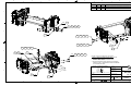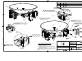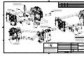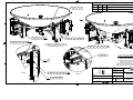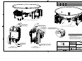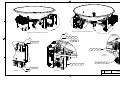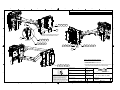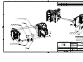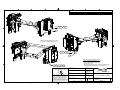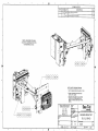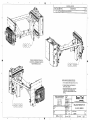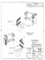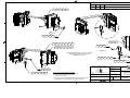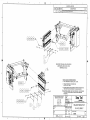
1
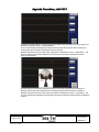
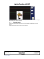
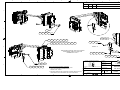
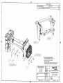
Upgrade P rocedure, x x 09 M K 2
1.1.
Upgrade Procedure, xx09 MK2 electronics
Upgrading an 09 Pedestal to MK2 electronics can be accomplished using the 132196 Upgrade Kit and the following
procedure. Please read this entire procedure before beginning work.
1.1.1.
Inventory the 132196 Upgrade Kit
Refer to the upgrade kit Bills Of Materials (BOM) at the end of this procedure. Make sure that you inventory
the BOM for the 132624-1 BALANCE WEIGHTS, xx09, MK2 that is included in the upgrade kit.
1.1.2.
Tools Required:
Screw Driver, Flat Blade, Small (1/8” blade)
Screw Driver, Phillips, Small (#1)
Diagonal Cutters
Wrench, Open End, 5/16” (8mm)
Wrench, Open End, 10mm
Wrench, Open End, 7/16” (11mm)
Wrench, Allen, 3/16” (5mm)
Lint free cloth with a small amount of acetone
Felt tip marker
1.1.3.
Cautions and Warnings
Dangerous voltages exist on the antenna pedestal, assure that power is secured at the antenna pedestal
breaker BEFORE commencing work.
While working inside the radome be cautious of pinch hazards in the area of the azimuth chain, the
elevation belt and the cross-level belt.
WARNING: Electrical Hazard – Dangerous AC Voltages exist on the
pedestal. Secure power at the Antenna Pedestal Breaker Box. Observe
proper safety precautions when working on the antenna pedestal inside the
radome.
CAUTION - PINCH HAZARD: Use extreme caution when your fingers are
near the chain drive system of this antenna, even when antenna power is
turned OFF. Do not put your fingers in between the chain and either sprocket.
CAUTION - PINCH HAZARD: Use extreme caution when your fingers are
near the belt drive systems of this antenna, even when antenna power is
turned OFF. Do not put your fingers in between the belt and either sprocket.
Page 2 of 64
Form # 117140-B
Document No
132622 Rev B
Upgrade P rocedure, x x 09 M K 2
1.1.4.
Overview of the Upgrade
In very simple terms, you will:
•
Remove the current Pedestal Control Unit (PCU), replace it with the MK2 PCU, Install a short
harness adapter and re-connect the cables.
•
Remove the GPS antenna (BNC type) and replace it with the new GPS antenna (RJ-11 type),
•
Replace the mini coaxes while replacing the cable ties, and terminate the coaxes at both ends.
•
Remove the current Motor Driver Enclosure (MDE), replace it with the MK2 MDE and re-connect
the cables.
1.1.5.
BUC Power Supply
Please note that you will NOT relocate your existing BUC Power Supply during this procedure.
1.1.6.
Changing the PCU
Use the following procedure for upgrading your current PCU with a MK2 PCU.
Page 3 of 64
Form # 117140-B
Document No
132622 Rev B
Upgrade P rocedure, x x 09 M K 2
1.
2.
3.
Using the 5/16” (8mm) open end
wrench remove the two coax
cables.
4.
5.
Remove the GPS (BNC) cable.
Using the small flat blade
screwdriver, remove the motor
control connector.
Remove the coax cables from the
switch assembly mounted on the
PCU. These coaxes will not be reused.
6.
Page 4 of 64
Form # 117140-B
Using the cutters, cut the large
cable tie on the power cord
connector and disconnect the
power cord.
Using the small flat blade
screwdriver, remove the PCU M&C
connector.
Document No
132622 Rev B
Upgrade P rocedure, x x 09 M K 2
Page 5 of 64
Form # 117140-B
7.
Using the 3/16” (5mm) Allen
wrench remove the 4 cap head
screws that mount the PCU to the
side pan. Retain these for later use.
8.
Install the 131298-5 adapter pigtail
to the 121485 feed harness
(removed from the “Polang” port of
the current PCU). Assure that the
retaining screws are tightened into
the harness connector
Document No
132622 Rev B
Upgrade P rocedure, x x 09 M K 2
Back of dish
9.
Apply Loctite 242 to the four cap
head screws removed in the
previous step.
3 SMA connectors
10. Mount the MK2 PCU using the four
cap head screws. With the dish up
at zenith (90° elevation) the PCU
will be mounted with the 3 SMA
connectors up toward the back of
the dish (as shown).
1.1.7.
Changing the GPS
Use the following procedure to change the GPS antenna with the new GPS antenna that is used with the
MK2 PCU.
1.
Page 6 of 64
Form # 117140-B
Using diagonal cutters, cut the
three ties along the edge of the dish
and any ties that join the GPS cable
to the other harnesses at the PCU.
Document No
132622 Rev B
Upgrade P rocedure, x x 09 M K 2
2.
Remove the two Phillips screws that
mount the existing GPS to its
bracket.
3.
Clean the upper surface of the
bracket thoroughly with a lint free
cloth and acetone solvent.
Apply the sticky side of the double
stick tape (124077-5 provided in
the upgrade kit) to the bracket.
Peel the paper off of the tape to
expose the second sticky side and
mount the new GPS to the tape
with the cable toward the cable tie
buttons.
Insert new 7” ties into the buttons
and secure the GPS cable along the
edge of the dish toward the PCU.
4.
5.
6.
Page 7 of 64
Form # 117140-B
Document No
132622 Rev B
Upgrade P rocedure, x x 09 M K 2
1.1.8.
MK2 PCU connections
Connect all the cables to the MK2 PCU.
1.
Connect the Orange mini coax (this
is the Cross-Pol coax which will
route to the LNB on the feed) SMA
connector to the “NC J1” port on
the MK2 PCU.
2.
Install the 113303-10 black jumper
coax from the “COM J3” port on the
MK2 PCU to the “L-Band” port on
the MK2 PCU
3.
Connect the Yellow mini coax (this
is the Co-Pol coax which will route
to opposite side of the antenna and
connect to the Co-Pol LNB OR be
terminated with an F bullet and tied
in place near the BUC) SMA
connector to the “NO J2” port on
the MK2 PCU.
Install adapter pigtail to the “Feed”
port on the MK2 PCU.
Install the “RX” coax to the “Rotary
Joint” port on the MK2 PCU.
Install the “RF M&C” cable to the
“RF M&C” port on the MK2 PCU. If
your harness has a female M&C
connector, you will need to install
the 9-pin gender changer (in the
upgrade kit), to enable you to plug
the harness into the RF M&C port.
4.
5.
6.
Page 8 of 64
Form # 117140-B
Document No
132622 Rev B
Upgrade P rocedure, x x 09 M K 2
7.
Install the power cable into the
power receptacle and install a 7”
cable tie through the P-clamp and
around the cable to prevent it from
loosening during vibration.
8.
Install the Motor Drive to the MDE
harness to the “Motor Control” port
on the PCU.
9.
Coil the excess GPS cable lenth and
use a cable tie to bind the coil.
10. Plug the GPS cable into the “GPS”
port on the MK2 PCU.
Page 9 of 64
Form # 117140-B
Document No
132622 Rev B
Upgrade P rocedure, x x 09 M K 2
1.1.9.
Routing the Cross-Pol and Co-Pol coaxes
Route, and terminate, the Cross-Pol and Co-Pol coaxes.
1.
Route the Orange and Yellow
coaxes to the bridge with the other
harness cables while omitting the
Cross-Pol and Co-Pol coaxes (both
have black shrink tubing at the
connectors). Cut several ties,
remove the previous Cross-Pol and
Co-Pol coaxes and tie the Orange
and Yellow coaxes into the harness
using the same tie points.
Cable Ties
2.
3.
The Orange coax will route off of
the bridge with the feed harness
and will be connected to the CrossPol LNB.
Replace 4” cable ties to join the
Cross-Pol coax to the Feed harness.
Feed harness routes off of the bridge near the waveguide
Page 10 of 64
Form # 117140-B
Document No
132622 Rev B
Upgrade P rocedure, x x 09 M K 2
4.
5.
Page 11 of 64
Form # 117140-B
Continue cutting and replacing the
ties to fininsh routing the Yellow
coax across the remainder of the
bridge.
If your system includes a
waveguide diplexer and Co-Pol LNB,
route the Yellow coax to the LNB
and tie the coax at several
convenient points.
6.
If your system does NOT include a
Co-Pol LNB, coil and tie the Yellow
coax near the BUC and install the F
bullet to prevent it from shorting
out.
7.
At the PCU, tie all of the cables
neatly together.
Document No
132622 Rev B
Upgrade P rocedure, x x 09 M K 2
1.1.10.
Replacing the Motor Driver Enclosure (MDE)
The following procedure for replacing the MDE.
1.
Remove and mark the 5 connectors,
one at a time, using the small flat
blade screwdriver and the felt tip
marker.
Drive - Motor Control Drive from the PCU.
Home – Home Flag Sensor
AZ – Azimuth Motor
EL – Elevation Motor
CL – Cross-Level Motor
2.
Page 12 of 64
Form # 117140-B
Cut the three ties on the side of the
MDE.
Document No
132622 Rev B
Upgrade P rocedure, x x 09 M K 2
3.
4.
5.
6.
7.
8.
9.
1.1.11.
Using the 10mm open end wrench,
remove the 4 10mm nuts (two on
top and two on the bottom of the
MDE) that mount the MDE to the
pedestal.
Remove the original MDE.
Apply loctite 242 to the four
threaded mounting bolts and
mount the MK2 MDE using the four
nuts removed in the previous step.
Reinstall the 5 connectors, one at a
time, using the small flat blade
screwdriver to secure the retainer
screws.
Install two 122782 push-in cable
ties by pressing the pointed end
into the vacant holes on the side of
the MDE and secure the home and
AZ cables to the MDE.
Install a 7” cable tie to secure the
TX & RX coaxes to the Home & AZ
cables.
Trim the excess length off of ALL
cable ties installed during this
upgrade.
Check PCU connections
WARNING: Verify that the “Service” and “USB” ports on the MK2 PCU are
VACANT prior to applying AC power to the antenna.
1.1.12.
Standard weight configurations
Change the course counter balance weight configuration:
1. Find the course balance weight kit for your specific model-dash number in the table below.
2. Remove the weights shown on the current configuration drawing. Combine these weights
together with the counter weights provided in this upgrade kit.
3. Install the weights shown on the MK2 configuration drawing to course balance your upgraded
antenna..
Page 13 of 64
Form # 117140-B
Document No
132622 Rev B
Upgrade P rocedure, x x 09 M K 2
Coarse balance configuration drawings
Description
BALANCE WEIGHT
BALANCE WEIGHT
BALANCE WEIGHT
BALANCE WEIGHT
BALANCE WEIGHT
MK2 UPGRADE
BALANCE WEIGHT
BALANCE WEIGHT
BALANCE WEIGHT
BALANCE WEIGHT
BALANCE WEIGHT
MK2 UPGRADE
BALANCE WEIGHT
BALANCE WEIGHT
BALANCE WEIGHT
BALANCE WEIGHT
BALANCE WEIGHT
MK2 UPGRADE
1.1.13.
KIT, EL & CL, 4009-11
KIT, EL & CL, 4009-17
KIT, EL & CL, 4009-23
KIT, EL & CL, 4009-33
POSITIONS, 4009-23/33
CURRENT
Configuration
130621-1
130338-1
130586-1
130548-1
KIT, EL & CL, 5009-11
KIT, EL & CL, 5009-17
KIT, EL & CL, 5009-23
KIT, EL & CL, 5009-33
POSITIONS, 5009-23/33
130157-1
129993-1
130375-1
130376-1
KIT, EL & CL, 6009-11
KIT, EL & CL, 6009-17
KIT, EL & CL, 6009-23
KIT, EL & CL, 6009-33
POSITIONS, 4009-23/33
130664-1
130654-1
130608-1
130295-1
MK2
Configuration
131921-1
131922-1
See Next row
134094-1
132412-1
131795-1
See Next row
TBD
131965-1
131966-1
See Next row
TBD
Antenna Initialization
Turn the pedestal power supply ON. The brakes on the Elevation and Cross-Level motors will release. A
brake release power supply control circuit supplies 24 VDC to the brakes initially (5-10 seconds) and then
reduces the voltage to 12VDC. The PCU will initialize the stabilized portion of the mass to be level with the
horizon and at a prescribed Azimuth and Elevation angles in the specific sequence of steps listed below.
Initialization is completed in the following phases, each phase must complete correctly for the antenna to
operate properly (post-initialization). Observe the Initialization of the antenna pedestal.
Step 1. Elevation axis activates - Input from the Elevation sensor is used to drive the Elevation of
the equipment frame to 45.0 degrees in elevation.
Step 2. Cross-Level axis activates - Input from the Cross-Level sensor is used to drive Cross-Level
of the equipment frame to bring it to level (this results in the tilt of the Cross-Level Beam being
level).
Step 3. Azimuth axis activates - Antenna drives CW in azimuth until the “Home Flag” signal is
produced. This signal is produced by a Proximity sensor in close proximity to a metal tab. After a
short period of time (a total of approximately 1-2 Minutes after power is initially applied to the
antenna), the PCU will report its model setting and software version number to the Antenna
Control Unit (ACU).
This completes the phases of initialization. At this time the antenna elevation should be at 45.0 degrees
and Relative azimuth should be at home flag (proximity sensor at the trailing edge of the metal tab in the
azimuth assembly).
Page 14 of 64
Form # 117140-B
Document No
132622 Rev B
Upgrade P rocedure, x x 09 M K 2
If any of these steps fail, or the ACU reports model "xx09", re-configure the PCU as described in the
Maintenance section of the Dealer Technical Manual. If initialization still fails, this indicates a drive or
sensor problem, refer to the Troubleshooting section.
1.1.14.
Balancing the Antenna
The antenna and equipment frame are balanced at the factory however, after disassembly for shipping or
maintenance, balance adjustment may be necessary. The elevation and cross-level motors have a brake
mechanism built into them, therefore, power must be ON to release the brakes and DishScan and
antenna drive must be OFF to balance the antenna. . Do NOT remove any of the drive belts.
Balancing is accomplished by adding or removing balance trim weights at strategic locations to keep the
antenna from falling forward/backward or side to side. The antenna system is not pendulous so 'balanced' is
defined as the antenna remaining at rest when left in any position.
The “REMOTE BALANCE” parameter (located at the end of the Remote Parameters after REMOTE TILT) of
the ACU. When enabled, Remote Balance Mode temporarily turns DishScan, Azimuth, Elevation and CrossLevel drive OFF. This function is required when trying to balance antenna systems that have built-in brakes
on the elevation and cross-level motors.
Assure that Antenna power is ON and that the antenna has completed initialization.
At the ACU:
From the ACU - REMOTE BALANCE parameter: Enable balance mode (refer to your ACU manual). The
screen should now display “REMOTE BALANCE ON”.
At the Antenna:
At the Antenna: Balance the antenna with the elevation near horizon (referred to as front to back
balance) by adding, or subtracting, small counter-weights.
Then balance Cross Level axis (referred to as left-right balance) by moving existing counterweights from the left to the right or from the right to the left. Always move weight from
one location on the equipment frame to the same location on the opposite side of the equipment
frame (ie from the top left of the reflector mounting frame to the top right of the reflector
mounting frame). Do NOT add counter-weight during this step.
Last, balance the antenna with the elevation pointed at, or near, zenith (referred to as top to bottom
balance) by moving existing counter-weights from the top to the bottom or from the
bottom to the top. Always move weight from one location on the equipment frame to the
same location on the opposite side of the equipment frame (ie from the top left of the reflector
mounting frame to the bottom left of the reflector mounting frame). Do NOT add counter-weight
during this step.
When completed, the antenna will stay at any position it is pointed in for at least 5 minutes (with no
ship motion).
Do NOT cycle antenna power to re-Initialize the antenna. Return to the ACU, which is still in
REMOTE BALANCE mode, and press ENTER to exit Remote Balance Mode. When you exit Balance
Mode the antenna will be re-initialized, which turns DishScan, Azimuth, Elevation and Cross-Level
drive ON.
1.1.15.
Fine Balance and Monitoring Motor Drive Torque
The DacRemP DISPTC graph chart provides a means for monitoring torque commands required for each
motor for diagnostic purposes and verifying antenna balance. By observing each trace, the required drive
of the antenna via the motor driver PCB may be established.
To view the Torque Commands, select the
graph chart.
This chart displays the Torque Command errors for each axis via three traces, CL (Cross Level), LV
(Elevation), and AZ (Azimuth), at a fixed 0.195amps/vertical division.
Page 15 of 64
Form # 117140-B
Document No
132622 Rev B
Upgrade P rocedure, x x 09 M K 2
A normal trace display will be ± 1 divisions from the red reference line while under calm sea conditions and
with DishScan Drive turned off. See example below
The Cross Level display will decrease (plots below red line) as the antenna requires drive to the left and
increase (plots above red line) as the antenna requires to the right.
Example: The antenna pictured in the screen capture below is imbalanced so that it is “Right Heavy”. The
CL trace is plotting above the red reference line (indicating that drive CCW is required to maintain a
90°Cross-Level position).
The Level display should decrease (plots below red line) as the antenna requires drive forward (Up in
elevation) and increase (plots above red line) as the antenna requires drive back (Down in elevation).
Example: The antenna pictured in the screen capture below is imbalanced so that it is “Front Heavy”. The
LV trace is plotting above the red line (indicating that drive CW is required to maintain the Current elevation
position).
Page 16 of 64
Form # 117140-B
Document No
132622 Rev B
Upgrade P rocedure, x x 09 M K 2
The Azimuth display should decrease (plots below red line) as the antenna is driven CCW and increase (plots
above red line) as the antenna is rotated CW.
1.1.16.
Testing the Antenna
Conduct the Functional Testing as described in the 131118 Series 09 Scheduled Inspections Record
manual.
If all functional tests are satisfactory, return to normal operations.
Page 17 of 64
Form # 117140-B
Document No
132622 Rev B
SINGLE LEVEL MFG BILL OF MATERIAL
FIND QTY
PART NO
REV DESCRIPTION
REFERENCE DESIGNATOR
1
1 EA 131057-1
B
ENCLOSURE ASS'Y, PCU, 09G2, 3 CH, 232
2
1 EA 131227-1
B
ENCLOSURE ASS'Y, MOTOR DRIVER, 09G2
3
1 EA 131381-1
B
GPS ANTENNA, SERIAL, AAA001005-G, NAV
5
1 EA 131298-5
X2 HARNESS ASS'Y, REFLECTOR, 09 UPGRADE
6
1 EA 113303-10
U
7
1 EA 128001-60ORG
A1 CABLE ASS'Y, RG-179 COAX, F(M) TO SMA
8
1 EA 128001-60YEL
A1 CABLE ASS'Y, RG-179 COAX, F(M) TO SMA
9
1 EA 132624-1
A
UPGRADE KIT, BALANCE WEIGHTS, XX09, M
10
10 EA 119801-012
B
CABLE TIE, NYLON, 4 IN, NATURAL
11
25 EA 119801-019
B
CABLE TIE, NYLON, 7.5 IN, NATURAL
12
1 EA 117319-4
E
LOCTITE PRODUCTS, 242 THREADLOCKER, .
13
1 EA 117319-30
E
LOCTITE PRODUCTS, 2760 THREADLOCKER,
14
1 IN 124077-5
B
TAPE, 3M VHB #4991, SYNTHETIC ADHESIV
15
6 EA 122782
16
1 EA 122976-1
A
DB 9 SLIM-LINE GENDER CHANGER, MALE T
18
1 EA 109391
A
ADAPTER, F(F)-F(F) (BULLET), 0.84 IN
19
1 EA 132622
A
PROCEDURE, UPGRADE, XX09 MK2
CABLE ASS'Y, SMA 90 - SMA (M), 8 IN
CABLE TIE, HOLDER, .281 DIA PUSH MOUN
UPGRADE KIT, XX09, MK2
PROD FAMILY
COMMON
EFF. DATE
2/8/2011
SHT 1 OF 2
DRAWING
NUMBER
132196-1
REV
B1
SINGLE LEVEL MFG BILL OF MATERIAL
FIND QTY
PART NO
REV DESCRIPTION
REFERENCE DESIGNATOR
1
6 EA 108519-4
G
WEIGHT, TRIM 7.0 OZ
2
1 EA 108519-1
G
WEIGHT, TRIM 4.0 OZ
3
1 EA 108519-3
G
WEIGHT, TRIM 6.0 OZ
4
2 EA 115420-2
G
TRIM WEIGHT, 10 X 3 X 3/8 IN
10
1 EA 126279-3
A2 NUT, 1 5/8 UNISTRUT, 1/4-20, W/SPRING
50
1 EA 114586-537
SCREW, HEX HD, 1/4-20 x 3/4, S.S.
51
1 EA 114586-538
SCREW, HEX HD, 1/4-20 x 1, S.S.
52
2 EA 114586-541
SCREW, HEX HD, 1/4-20 x 1-1/2, S.S.
53
1 EA 114586-545
SCREW, HEX HD, 1/4-20 x 2-1/2, S.S.
54
1 EA 114586-542
SCREW, HEX HD, 1/4-20 x 1-3/4, S.S.
58
7 EA 114580-029
WASHER, FLAT, 1/4, S.S.
59
1 EA 114583-029
NUT, HEX, 1/4-20, S.S.
60
1 EA 132622
A
PROCEDURE, UPGRADE, XX09 MK2
REFERENCE ONLY
UPGRADE KIT, BALANCE WEIGHTS, XX09, MK2
PROD FAMILY
COMMON
EFF. DATE
2/8/2011
SHT 1 OF 1
DRAWING
NUMBER
132624-1
REV
A
SINGLE LEVEL MFG BILL OF MATERIAL
FIND QTY
PART NO
REV DESCRIPTION
REFERENCE DESIGNATOR
1
5 EA 108519-4
G
WEIGHT, TRIM 7.0 OZ
3
2 EA 118560
C
WEIGHT, TRIM, 1 x 3.38 x 3, 2.8 LBS
5
2 EA 112573-2
C
WEIGHT, TRIM, 1/2 x 2.75 x 3, 1.17 LB
10
2 EA 126279-3
A2 NUT, 1 5/8 UNISTRUT, 1/4-20, W/SPRING
51
1 EA 114586-540
SCREW, HEX HD, 1/4-20 x 1-1/4, S.S.
52
7 EA 114586-542
SCREW, HEX HD, 1/4-20 x 1-3/4, S.S.
53
1 EA 114586-541
SCREW, HEX HD, 1/4-20 x 1-1/2, S.S.
58
15 EA 114580-029
WASHER, FLAT, 1/4, S.S.
59
6 EA 114583-029
NUT, HEX, 1/4-20, S.S.
BALANCE WEIGHT KIT, EL & CL, 4009-11
PROD FAMILY
COMMON
EFF. DATE
2/8/2011
SHT 1 OF 1
DRAWING
NUMBER
130621-1
REV
B
8
6
7
5
4
2
3
REV
1
REVISION HISTORY
DESCRIPTION
ECO# DATE
BY
A
6769
07/10/09
ITEM 1 WAS QTY 4; ITEM 3 WAS QTY 1; ITEM 4 WAS 108519-2; ITEM 10 WAS QTY 4; ITEM 51 WAS QTY 2; ITEM 52 WAS QTY 2;
ITEM 58 WAS QTY 7; ADDED ITEMS 5 & 59; RELEASED TO PRODUCTION, WAS X1.
B
6831
09/10/09
ITEM 1 WAS QTY 2. DELETED ITEMS 2 & 4. ITEM 3 WAS QTY 1. ITEM 10 WAS QTY 4. MISCELLANEOUS HARDWARE CHANGES.
CHANGED VIEWS TO DISPLAY NEW WEIGHT CONFIGURATION.
K.D.H.
KRB
D
D
2X
1
2X
52
58
58
59
C
C
5
52
51
53
58
1
58
58
58
59
58
59
5
1
1
B
B
52
58
2X
3
2X
52
58
58
59
NOTES: UNLESS OTHERWISE SPECIFIED
1. APPLY ADHESIVE PER SEATEL SPEC. 121730.
2. TORQUE THREADED FASTENERS PER
SEATEL SPEC. 122305.
3. BALANCE WEIGHTS ARE SHOWN AS STARTING
WEIGHTS ONLY. TRIM WEIGHTS MAY BE NEEDED
TO ACHIEVE BALANCE.
UNLESS OTHERWISE SPECIFIED
DIMENSIONS ARE IN INCHES.
X.X = .050
X.XX = .020
X.XXX = .005
ANGLES: .5
A
DRAWN BY:
KRB
DRAWN DATE:
06/12/09
Tel. 925-798-7979 Fax. 925-798-7986
APPROVED BY:
BALANCE WEIGHT KIT,
INTERPRET TOLERANCING PER ASME Y14.5M - 1994
10
APPROVED DATE:
MATERIAL:
2X
FINISH:
N/A
3rd ANGLE
PROJECTION
8
7
EL & CL, 4009-11
N/A
3
6
5
4
SIZE
SCALE:
B
1:8
FIRST USED:
3
A
TITLE:
REV
DRAWING NUMBER
130621
4009
B
1 OF 1
SHEET NUMBER
2
1
SINGLE LEVEL MFG BILL OF MATERIAL
FIND QTY
PART NO
REV DESCRIPTION
REFERENCE DESIGNATOR
1
10 EA 108519-4
G
WEIGHT, TRIM 7.0 OZ
2
3 EA 108519-3
G
WEIGHT, TRIM 6.0 OZ
3
1 EA 118560
C
WEIGHT, TRIM, 1 x 3.38 x 3, 2.8 LBS
4
1 EA 108519-1
G
WEIGHT, TRIM 4.0 OZ
5
2 EA 115420-2
G
TRIM WEIGHT, 10 X 3 X 3/8 IN
10
1 EA 126279-3
A2 NUT, 1 5/8 UNISTRUT, 1/4-20, W/SPRING
50
1 EA 114586-538
SCREW, HEX HD, 1/4-20 x 1, S.S.
51
3 EA 114586-541
SCREW, HEX HD, 1/4-20 x 1-1/2, S.S.
52
4 EA 114586-542
SCREW, HEX HD, 1/4-20 x 1-3/4, S.S.
53
2 EA 114586-544
SCREW, HEX HD, 1/4-20 x 2-1/4, S.S.
58
15 EA 114580-029
WASHER, FLAT, 1/4, S.S.
59
5 EA 114583-029
NUT, HEX, 1/4-20, S.S.
BALANCE WEIGHT KIT, EL & CL, 4009-11, MK2
PROD FAMILY
COMMON
EFF. DATE
2/8/2011
SHT 1 OF 1
DRAWING
NUMBER
131921-1
REV
A1
8
6
7
5
4
REV
A
D
50
51
58
4
1
58
2
3
1
REVISION HISTORY
DESCRIPTION
ECO# DATE
BY
A
7194
03/30/10
RELEASED TO PRODUCTION. WAS REVISION X1.
KRB
A1
N/A
05/14/10
CHANGED TITLE.
KRB
58
D
2
59
DETAIL C
C
EQUIPMENT FRAME & ANTENNA
ASSEMBLIES SHOWN FOR
REFERENCE ONLY
B
53
58
2
1
C
52
1
58
1
2
1
1
53
58
58
2X
1
59
C
52
B
B
3
51
DETAIL A
2X
52
58
58
59
2X
10
UNLESS OTHERWISE SPECIFIED
DIMENSIONS ARE IN INCHES.
A
4
51
58
1
X.X = .050
X.XX = .020
X.XXX = .005
ANGLES: .5
NOTES: UNLESS OTHERWISE SPECIFIED
1. APPLY ADHESIVE PER SEATEL SPEC. 121730.
1
2. TORQUE THREADED FASTENERS PER
SEATEL SPEC. 122305.
7
4 WEIGHTS INDICATED THAT LESS THAN 4 OUNCES
ARE SHOWN FOR REFERENCE ONLY.
6
5
4
3rd ANGLE
PROJECTION
02/19/10
5
Tel. 925-798-7979 Fax. 925-798-7986
APPROVED BY:
A
TITLE:
BALANCE WEIGHT KIT,
SIZE
SCALE:
B
1:8
FIRST USED:
3
59
KRB
EL & CL, 4009-11, MK2
N/A
N/A
58
DRAWN DATE:
APPROVED DATE:
FINISH:
58
DRAWN BY:
INTERPRET TOLERANCING PER ASME Y14.5M - 1994
MATERIAL:
3. BALANCE WEIGHTS ARE SHOWN AS STARTING
WEIGHTS ONLY. TRIM WEIGHTS MAY BE NEEDED
TO ACHIEVE BALANCE.
DETAIL B
8
58
REV
DRAWING NUMBER
131921
4009
A1
1 OF 1
SHEET NUMBER
2
1
SINGLE LEVEL MFG BILL OF MATERIAL
FIND QTY
PART NO
REV DESCRIPTION
REFERENCE DESIGNATOR
1
1 EA 108519-2
G
WEIGHT, TRIM 5.0 OZ
2
1 EA 112573-2
C
WEIGHT, TRIM, 1/2 x 2.75 x 3, 1.17 LB
3
2 EA 118560
C
WEIGHT, TRIM, 1 x 3.38 x 3, 2.8 LBS
5
4 EA 108519-4
G
WEIGHT, TRIM 7.0 OZ
10
2 EA 126279-3
A2 NUT, 1 5/8 UNISTRUT, 1/4-20, W/SPRING
50
1 EA 114586-537
SCREW, HEX HD, 1/4-20 x 3/4, S.S.
51
1 EA 114586-541
SCREW, HEX HD, 1/4-20 x 1-1/2, S.S.
52
6 EA 114586-542
SCREW, HEX HD, 1/4-20 x 1-3/4, S.S.
58
12 EA 114580-029
WASHER, FLAT, 1/4, S.S.
59
4 EA 114583-029
NUT, HEX, 1/4-20, S.S.
BALANCE WEIGHT KIT, EL & CL, 4009-17
PROD FAMILY
COMMON
EFF. DATE
2/8/2011
SHT 1 OF 1
DRAWING
NUMBER
130338-1
REV
C
8
6
7
51
58
5
5
4
2
3
REV
5
ECO# DATE
1
REVISION HISTORY
DESCRIPTION
BY
A
6769
07/10/09
ITEM 2 WAS QTY 2; ITEM 50 WAS QTY 1; ITEM 51 WAS QTY 4 OF 114585-524; ITEM 58 WAS QTY 5; ADDED ITEMS 4, 5 & 52.
RELEASED TO PRODUCTION, WAS X1.
B
6831
09/10/09
DELETED ITEMS 1 & 4. ITEM 3 WAS QTY 1. ITEM 5 WAS QTY 2. ITEM 10 WAS QTY4. MISCELLANEOUS HARDWARE CHANGES.
CHANGED VIEWS TO DISPLAY NEW WEIGHT CONFIGURATIONS.
C
7438
8-31-10
K.D.H.
KRB
K.D.H.
ITEM 58 WAS QTY 11; ADD ITEMS 1 & 50; UPDATE TITLE BLOCK
D
D
52
58
3
2X
2X
52
58
58
59
C
C
10
2X
3
52
58
58
59
2X
2X
B
5
B
2
NOTES: UNLESS OTHERWISE SPECIFIED
1. APPLY ADHESIVE PER SEATEL SPEC. 121730.
2. TORQUE THREADED FASTENERS PER
SEATEL SPEC. 122305.
3. BALANCE WEIGHTS ARE SHOWN AS STARTING
WEIGHTS ONLY. TRIM WEIGHTS MAY BE NEEDED
TO ACHIEVE BALANCE.
1
58
UNLESS OTHERWISE SPECIFIED
DIMENSIONS ARE IN INCHES.
50
X.X = .050
X.XX = .020
X.XXX = .005
ANGLES: .5
A
DESIGNER/ENGINEER:
DRAWN BY:
WEIGHT:
DRAWN DATE:
MATERIAL:
APPROVED BY:
KRB
05/28/09
Tel. 925-798-7979 Fax. 925-798-7986
N/A
BALANCE WEIGHT KIT,
INTERPRET TOLERANCING PER ASME Y14.5 - 2009
FINISH:
This drawing and specifications are the property
of Cobham PLC. Neither this document, the
N/A
information, or the specifications disclosed shall
be reproduced or transferred in whole or in part
SURFACE ROUGHNESS:
for any purpose without the specific written
authorization of Cobham PLC. This restriction
is applicable regardless of the source from which
the document is obtained. Any violation of this policy
3rd ANGLE
is a violation of the Trade Secrets Act and subject
PROJECTION
to prosecution to the fullest extent of the law.
8
7
6
5
4
A
TITLE:
APPROVED DATE:
SIZE
SCALE:
B
1:6
FIRST USED:
3
EL & CL, 4009-17
REV
DRAWING NUMBER
130338
4009
C
1 OF 1
SHEET NUMBER
2
1
SINGLE LEVEL MFG BILL OF MATERIAL
FIND QTY
PART NO
REV DESCRIPTION
REFERENCE DESIGNATOR
1
2 EA 115420-2
G
TRIM WEIGHT, 10 X 3 X 3/8 IN
2
10 EA 108519-4
G
WEIGHT, TRIM 7.0 OZ
3
3 EA 108519-3
G
WEIGHT, TRIM 6.0 OZ
4
1 EA 108519-1
G
WEIGHT, TRIM 4.0 OZ
50
1 EA 114586-538
SCREW, HEX HD, 1/4-20 x 1, S.S.
51
3 EA 114586-541
SCREW, HEX HD, 1/4-20 x 1-1/2, S.S.
52
3 EA 114586-542
SCREW, HEX HD, 1/4-20 x 1-3/4, S.S.
53
1 EA 114586-543
SCREW, HEX HD, 1/4-20 x 2, S.S.
54
1 EA 114586-545
SCREW, HEX HD, 1/4-20 x 2-1/2, S.S.
58
14 EA 114580-029
WASHER, FLAT, 1/4, S.S.
59
5 EA 114583-029
NUT, HEX, 1/4-20, S.S.
BALANCE WEIGHT KIT, EL & CL, 4009-17, MK2
PROD FAMILY
COMMON
EFF. DATE
2/8/2011
SHT 1 OF 1
DRAWING
NUMBER
131922-1
REV
A1
8
6
7
5
4
REV
51
58
2
2
3
2
1
REVISION HISTORY
DESCRIPTION
ECO# DATE
BY
A
7194
03/30/10
RELEASED TO PRODUCTION. WAS REVISION X1.
KRB
A1
N/A
05/14/10
CHANGED TITLE.
KRB
D
D
A
C
C
52
53
58
2
2
2
58
2
2
4
52
58
3
2
58
59
4
PARTIAL EQUIPEMENT FRAME
& ANTENNA ASSEMBLIES SHOWN
FOR REFERENCE ONLY
52
58
2
4
58
59
4
B
B
B
50
2X
58
2
2. TORQUE THREADED FASTENERS PER
SEATEL SPEC. 122305.
1
3. BALANCE WEIGHTS ARE SHOWN AS STARTING
WEIGHTS ONLY. TRIM WEIGHTS MAY BE NEEDED
TO ACHIEVE BALANCE.
4 WEIGHTS WEIGHING LESS THAN 4 OUNCES
ARE SHOWN FOR REFERENCE ONLY.
UNLESS OTHERWISE SPECIFIED
DIMENSIONS ARE IN INCHES.
A
54
DETAIL B
58
3
3
58
59
4
X.X = .050
X.XX = .020
X.XXX = .005
ANGLES: .5
DETAIL A
2X
51
58
58
02/22/10
Tel. 925-798-7979 Fax. 925-798-7986
APPROVED BY:
FINISH:
5
4
BALANCE WEIGHT KIT,
SIZE
SCALE:
B
1:6
FIRST USED:
3
A
TITLE:
EL & CL, 4009-17, MK2
N/A
59
3rd ANGLE
PROJECTION
6
KRB
DRAWN DATE:
APPROVED DATE:
N/A
7
DRAWN BY:
INTERPRET TOLERANCING PER ASME Y14.5M - 1994
MATERIAL:
8
NOTES: UNLESS OTHERWISE SPECIFIED
1. APPLY ADHESIVE PER SEATEL SPEC. 121730.
REV
DRAWING NUMBER
131922
4009
A1
1 OF 1
SHEET NUMBER
2
1
SINGLE LEVEL MFG BILL OF MATERIAL
FIND QTY
PART NO
REV DESCRIPTION
REFERENCE DESIGNATOR
1
1 EA 118560
C
WEIGHT, TRIM, 1 x 3.38 x 3, 2.8 LBS
2
3 EA 112573-2
C
WEIGHT, TRIM, 1/2 x 2.75 x 3, 1.17 LB
4
1 EA 108519-4
G
WEIGHT, TRIM 7.0 OZ
5
3 EA 108519-3
G
WEIGHT, TRIM 6.0 OZ
6
1 EA 108519-2
G
WEIGHT, TRIM 5.0 OZ
7
1 EA 108519-1
G
WEIGHT, TRIM 4.0 OZ
10
2 EA 126279-3
A2 NUT, 1 5/8 UNISTRUT, 1/4-20, W/SPRING
50
5 EA 114586-537
SCREW, HEX HD, 1/4-20 x 3/4, S.S.
51
6 EA 114586-542
SCREW, HEX HD, 1/4-20 x 1-3/4, S.S.
58
14 EA 114580-029
WASHER, FLAT, 1/4, S.S.
59
4 EA 114583-029
NUT, HEX, 1/4-20, S.S.
BALANCE WEIGHT KIT, EL & CL, 4009-23
PROD FAMILY
COMMON
EFF. DATE
2/8/2011
SHT 1 OF 1
DRAWING
NUMBER
130586-1
REV
A
SINGLE LEVEL MFG BILL OF MATERIAL
FIND QTY
PART NO
REV DESCRIPTION
REFERENCE DESIGNATOR
2
2 EA 112573-2
C
WEIGHT, TRIM, 1/2 x 2.75 x 3, 1.17 LB
3
1 EA 118560
C
WEIGHT, TRIM, 1 x 3.38 x 3, 2.8 LBS
6
1 EA 108519-4
G
WEIGHT, TRIM 7.0 OZ
10
2 EA 126279-3
A2 NUT, 1 5/8 UNISTRUT, 1/4-20, W/SPRING
50
4 EA 114586-537
SCREW, HEX HD, 1/4-20 x 3/4, S.S.
51
4 EA 114586-542
SCREW, HEX HD, 1/4-20 x 1-3/4, S.S.
58
10 EA 114580-029
WASHER, FLAT, 1/4, S.S.
59
2 EA 114583-029
NUT, HEX, 1/4-20, S.S.
BALANCE WEIGHT KIT, EL & CL, 4009-33
PROD FAMILY
COMMON
EFF. DATE
2/8/2011
SHT 1 OF 1
DRAWING
NUMBER
130548-1
REV
A1
8
6
7
5
4
2
3
REV
1
REVISION HISTORY
DESCRIPTION
ECO# DATE
BY
A
6771
07/08/09
RELEASED TO PRODUCTION. NO PRIOR REVISION.
KRB
A1
6854
09/11/09
REPOSITIONED WEIGHTS WITHIN ASSEMBLY. ADDED NOTE 5.
KRB
D
D
50
58
4
A
C
C
50
58
2X
59
2X
4
51
B
2
3
5
2X
10
58
58
B
DETAIL B
(BRIDGE NOT SHOWN
FOR CLARITY)
4
50
58
2X
58
51
50
58
56
B
UNLESS OTHERWISE SPECIFIED
DIMENSIONS ARE IN INCHES.
DETAIL A
(LEVEL BEAM NOT
SHOWN FOR CLARITY)
A
X.X = .050
X.XX = .020
X.XXX = .005
ANGLES: .5
NOTES: UNLESS OTHERWISE SPECIFIED
1. APPLY ADHESIVE PER SEATEL SPEC. 121730.
2. TORQUE THREADED FASTENERS PER
SEATEL SPEC. 122305.
3. BALANCE WEIGHTS ARE SHOWN AS STARTING WEIGHTS ONLY.
N/A
TRIM WEIGHTS MAY BE NEEDED TO ACHIEVE BALANCE.
4 WEIGHTS INDICATED ARE LESS THAN 4 OUNCES AND
FINISH:
ARE SHOWN FOR REFERENCE ONLY.
N/A
5 ABUT INDICATED WEIGHT TO SSPA BRACKET WHEN
INSTALLING ON EQUIPMENT FRAME.
7
6
5
KRB
DRAWN DATE:
07/09/09
Tel. 925-798-7979 Fax. 925-798-7986
APPROVED BY:
BALANCE WEIGHT KIT,
APPROVED DATE:
4
3rd ANGLE
PROJECTION
SIZE
SCALE:
B
1:8
FIRST USED:
3
A
TITLE:
INTERPRET TOLERANCING PER ASME Y14.5M - 1994
MATERIAL:
8
DRAWN BY:
EL & CL, 4009-33
REV
DRAWING NUMBER
130548
4009
A1
1 OF 1
SHEET NUMBER
2
1
Upgrade P rocedure, x x 09 M K 2
134094-1
BALANCE WEIGHT POSITIONS, 4009-23/33 MK2 UPGRADE
Refer to BOM 132624-1 UPGRADE KIT, BALANCE WEIGHTS, XX09, MK2
Page 32 of 64
Form # 117140-B
Document No
132622 Rev B
8
6
7
5
4
2
3
REV
A
REVISION HISTORY
DESCRIPTION
ECO# DATE
8332
02/04/11
1
BY
KRB
RELEASED TO PRODUCTION. NO PRIOR REVISION.
D
D
A
C
C
4009-33, MK2 UPGRADE SHOWN
6
2X
B
7
54
58
10
2X
54
58
58
51
c
59
58
4009-33, MK2 UPGRADE SHOWN
1
51
58
8
1
B
B
NOTES: UNLESS OTHERWISE SPECIFIED
1. APPLY ADHESIVE PER SEATEL SPEC. 121730.
2. TORQUE THREADED FASTENERS PER
SEATEL SPEC. 122305.
DETAIL C
3. BALANCE WEIGHTS ARE SHOWN AS STARTING WEIGHTS ONLY.
TRIM WEIGHTS MAY BE NEEDED TO ACHIEVE BALANCE.
4. DRAWING IS FOR REFERENCE ONLY. FOR BUBBLE I.D. PART
IDENTIFICATION, REFER TO BOM 132624-1.
UNLESS OTHERWISE SPECIFIED
DIMENSIONS ARE IN INCHES.
2X
A
DETAIL A
(LEVEL BEAM NOT
SHOWN FOR CLARITY)
54
2X
5
58
10
54
58
1
1
X.X = .050
X.XX = .020
X.XXX = .005
ANGLES: .5
10
7
KRB
DRAWN DATE:
02/04/11
Tel. 925-798-7979 Fax. 925-798-7986
APPROVED BY:
DETAIL B
(BRIDGE NOT SHOWN
FOR CLARITY)
BALANCE WEIGHT POSITIONS
APPROVED DATE:
6
4009-23/33 MK2 UPGRADE
N/A
FINISH:
N/A
5
4
SIZE
SCALE:
B
1:8
FIRST USED:
3
A
TITLE:
INTERPRET TOLERANCING PER ASME Y14.5M - 1994
MATERIAL:
3rd ANGLE
PROJECTION
8
DRAWN BY:
REV
DRAWING NUMBER
134094
4009
A
1 OF 2
SHEET NUMBER
2
1
8
6
7
5
4
2
3
1
D
D
E
C
C
F
D
4009-23, MK2 UPGRADE SHOWN
4009-23, MK2 UPGRADE SHOWN
7
2X
54
58
58
59
6
51
2X
54
58
58
1
10
B
B
54
58
3
1
DETAIL F
SCALE 1 : 4
52
54
A
2X
DETAIL D
51
58
58
1
1
58
8
8
1
10
A
10
DETAIL E
5
SIZE
SCALE:
B
1:8
DRAWING NUMBER
REV
134094
A
2 OF 2
SHEET NUMBER
8
7
6
5
4
3
2
1
SINGLE LEVEL MFG BILL OF MATERIAL
FIND QTY
PART NO
REV DESCRIPTION
REFERENCE DESIGNATOR
1
1 EA 126026
B
AZ COUNTER WEIGHT MOD
2
2 EA 112573-2
C
WEIGHT, TRIM, 1/2 x 2.75 x 3, 1.17 LB
3
2 EA 118560
C
WEIGHT, TRIM, 1 x 3.38 x 3, 2.8 LBS
50
4 EA 114586-542
SCREW, HEX HD, 1/4-20 x 1-3/4, S.S.
51
2 EA 114586-546
SCREW, HEX HD, 1/4-20 x 2-3/4, S.S.
58
12 EA 114580-029
WASHER, FLAT, 1/4, S.S.
59
6 EA 114583-029
NUT, HEX, 1/4-20, S.S.
BALANCE WEIGHT KIT, EL & CL, 5009-11
PROD FAMILY
COMMON
EFF. DATE
2/8/2011
SHT 1 OF 1
DRAWING
NUMBER
130157-1
REV
X1
Upgrade P rocedure, x x 09 M K 2
DWG Pg 1
- NOT AVAILABLE YET
Page 36 of 64
Form # 117140-B
Document No
132622 Rev B
SINGLE LEVEL MFG BILL OF MATERIAL
FIND QTY
PART NO
REV DESCRIPTION
REFERENCE DESIGNATOR
1
2 EA 118560
C
WEIGHT, TRIM, 1 x 3.38 x 3, 2.8 LBS
2
1 EA 112573-2
C
WEIGHT, TRIM, 1/2 x 2.75 x 3, 1.17 LB
3
3 EA 108519-4
G
WEIGHT, TRIM 7.0 OZ
51
3 EA 114586-540
SCREW, HEX HD, 1/4-20 x 1-1/4, S.S.
52
5 EA 114586-542
SCREW, HEX HD, 1/4-20 x 1-3/4, S.S.
58
16 EA 114580-029
WASHER, FLAT, 1/4, S.S.
59
8 EA 114583-029
NUT, HEX, 1/4-20, S.S.
BALANCE WEIGHT KIT, EL & CL, 5009-11, MK2
PROD FAMILY
COMMON
EFF. DATE
2/8/2011
SHT 1 OF 1
DRAWING
NUMBER
132412-1
REV
A
8
5
6
7
4
2
3
REV
ECO# DATE
A
7329
7329
1
REVISION HISTORY
DESCRIPTION
BY
SL
REELEASE TO PRODUCTION. REV WAS X1.
D
D
3
2X
52
58
58
59
1
PARTIAL EQUIPMENT FRAME ASS'Y
SHOWN FOR REFERENCE ONLY.
C
C
2
DETAIL A
51
52
58
58
58
58
59
59
52
58
58
59
2X
51
58
3
58
59
1
B
B
NOTES: UNLESS OTHERWISE SPECIFIED
1. APPLY ADHESIVE PER SEATEL SPEC. 121730.
2. TORQUE THREADED FASTENERS PER
SEATEL SPEC. 122305.
51
58
3
58
UNLESS OTHERWISE SPECIFIED
DIMENSIONS ARE IN INCHES.
X.X = .050
X.XX = .020
X.XXX = .005
ANGLES: .5
A
3. BALANCE WEIGHTS ARE SHOWN AS STARTING WEIGHTS ONLY.
TRIM WEIGHTS MAY BE NEEDED TO ACHIEVE BALANCE.
59
DESIGNER/ENGINEER:
DRAWN BY:
WEIGHT:
DRAWN DATE:
MATERIAL:
APPROVED BY:
KRB
06/03/10
Tel. 925-798-7979 Fax. 925-798-7986
BALANCE WEIGHT KIT,
INTERPRET TOLERANCING PER ASME Y14.5 - 2009
FINISH:
This drawing and specifications are the property
of Cobham PLC. Neither this document, the
N/A
information, or the specifications disclosed shall
be reproduced or transferred in whole or in part
SURFACE
ROUGHNESS:
for any purpose without the specific written
authorization of Cobham PLC. This restriction
is applicable regardless of the source from which
the document is obtained. Any violation of this policy
3rd ANGLE
is a violation of the Trade Secrets Act and subject
PROJECTION
to prosecution to the fullest extent of the law.
8
7
6
5
4
A
TITLE:
N/A
APPROVED DATE:
SIZE
SCALE:
B
1:6
FIRST USED:
3
EL & CL, 5009-11, MK2
REV
DRAWING NUMBER
132412
5009
A
1 OF 1
SHEET NUMBER
2
1
SINGLE LEVEL MFG BILL OF MATERIAL
FIND QTY
PART NO
REV DESCRIPTION
REFERENCE DESIGNATOR
1
1 EA 126026
B
AZ COUNTER WEIGHT MOD
2
2 EA 112573-2
C
WEIGHT, TRIM, 1/2 x 2.75 x 3, 1.17 LB
3
2 EA 118560
C
WEIGHT, TRIM, 1 x 3.38 x 3, 2.8 LBS
50
4 EA 114586-542
SCREW, HEX HD, 1/4-20 x 1-3/4, S.S.
51
2 EA 114586-546
SCREW, HEX HD, 1/4-20 x 2-3/4, S.S.
58
12 EA 114580-029
WASHER, FLAT, 1/4, S.S.
59
6 EA 114583-029
NUT, HEX, 1/4-20, S.S.
BALANCE WEIGHT KIT, EL & CL, 5009-17
PROD FAMILY
COMMON
EFF. DATE
2/8/2011
SHT 1 OF 1
DRAWING
NUMBER
129993-1
REV
A
8
6
7
5
4
2
3
REV
A
REVISION HISTORY
DESCRIPTION
ECO# DATE
N/A
04/15/09
1
BY
KRB
RELEASE TO PRODUCTION, NO PRIOR REVISION.
D
D
EQUIPMENT FRAME
SHOWN FOR REFERENCE
ONLY
C
C
1
50
58
58
59
2X
3
B
50
58
58
59
B
2X
NOTES: UNLESS OTHERWISE SPECIFIED
1. APPLY ADHESIVE PER SEATEL SPEC. 121730.
2. TORQUE THREADED FASTENERS PER
SEATEL SPEC. 122305.
3. WEIGHTS SHOWN ARE A STARTING POINT
ONLY. TRIM AS NECESSARY TO ACHIEVE
BALANCE.
UNLESS OTHERWISE SPECIFIED
DIMENSIONS ARE IN INCHES.
51
58
58
59
2X
A
2
X.X = .050
X.XX = .020
X.XXX = .005
ANGLES: .5
2X
DRAWN BY:
KRB
DRAWN DATE:
04/15/09
Tel. 925-798-7979 Fax. 925-798-7986
APPROVED BY:
EL & CL BALANCE
INTERPRET TOLERANCING PER ASME Y14.5M - 1994
APPROVED DATE:
MATERIAL:
FINISH:
N/A
3rd ANGLE
PROJECTION
8
7
WEIGHT KIT, 5009-17
N/A
3
6
5
4
SIZE
SCALE:
B
1:6
FIRST USED:
3
A
TITLE:
REV
DRAWING NUMBER
129993
XX09
2
A
1 OF 1
SHEET NUMBER
1
SINGLE LEVEL MFG BILL OF MATERIAL
FIND QTY
PART NO
REV DESCRIPTION
REFERENCE DESIGNATOR
1
2 EA 118560
C
WEIGHT, TRIM, 1 x 3.38 x 3, 2.8 LBS
2
2 EA 108519-4
G
WEIGHT, TRIM 7.0 OZ
51
2 EA 114586-540
SCREW, HEX HD, 1/4-20 x 1-1/4, S.S.
52
4 EA 114586-542
SCREW, HEX HD, 1/4-20 x 1-3/4, S.S.
58
12 EA 114580-029
WASHER, FLAT, 1/4, S.S.
59
6 EA 114583-029
NUT, HEX, 1/4-20, S.S.
BALANCE WEIGHT KIT, EL & CL, 5009-17, MK2
PROD FAMILY
COMMON
EFF. DATE
2/8/2011
SHT 1 OF 1
DRAWING
NUMBER
131795-1
REV
A
8
7
6
5
4
2
3
REV
A
ECO# DATE
7329
06-24-10
1
REVISION HISTORY
DESCRIPTION
BY
SL
RELEASE TO PRODUCTION. REV WAS X1.
D
D
2X
52
58
58
59
1
C
C
PARTIAL EQUIPMENT FRAME ASS'Y
SHOWN FOR REFERENCE ONLY.
52
58
58
59
2X
B
B
1
NOTES: UNLESS OTHERWISE SPECIFIED
1. APPLY ADHESIVE PER SEATEL SPEC. 121730.
2. TORQUE THREADED FASTENERS PER
SEATEL SPEC. 122305.
51
58
2
58
59
3. BALANCE WEIGHTS ARE SHOWN AS STARTING WEIGHTS ONLY.
TRIM WEIGHTS MAY BE NEEDED TO ACHIEVE BALANCE.
UNLESS OTHERWISE SPECIFIED
DIMENSIONS ARE IN INCHES.
X.X = .050
X.XX = .020
X.XXX = .005
ANGLES: .5
A
DESIGNER/ENGINEER:
DRAWN BY:
WEIGHT:
DRAWN DATE:
MATERIAL:
APPROVED BY:
KRB
06/03/10
Tel. 925-798-7979 Fax. 925-798-7986
BALANCE WEIGHT KIT
INTERPRET TOLERANCING PER ASME Y14.5 - 2009
FINISH:
This drawing and specifications are the property
of Cobham PLC. Neither this document, the
N/A
information, or the specifications disclosed shall
be reproduced or transferred in whole or in part
SURFACE
ROUGHNESS:
for any purpose without the specific written
authorization of Cobham PLC. This restriction
is applicable regardless of the source from which
the document is obtained. Any violation of this policy
3rd ANGLE
is a violation of the Trade Secrets Act and subject
PROJECTION
to prosecution to the fullest extent of the law.
8
7
6
5
4
A
TITLE:
N/A
APPROVED DATE:
SIZE
SCALE:
B
1:6
FIRST USED:
3
EL & CL, 5009-17, MK2
REV
DRAWING NUMBER
131795
5009
A
1 OF 1
SHEET NUMBER
2
1
SINGLE LEVEL MFG BILL OF MATERIAL
FIND QTY
PART NO
REV DESCRIPTION
REFERENCE DESIGNATOR
2
1 EA 112573-2
C
WEIGHT, TRIM, 1/2 x 2.75 x 3, 1.17 LB
3
5 EA 108519-4
G
WEIGHT, TRIM 7.0 OZ
50
2 EA 114586-541
SCREW, HEX HD, 1/4-20 x 1-1/2, S.S.
51
2 EA 114586-542
SCREW, HEX HD, 1/4-20 x 1-3/4, S.S.
52
1 EA 114586-544
SCREW, HEX HD, 1/4-20 x 2-1/4, S.S.
58
8 EA 114580-029
WASHER, FLAT, 1/4, S.S.
59
4 EA 114583-029
NUT, HEX, 1/4-20, S.S.
BALANCE WEIGHT KIT, EL & CL, 5009-23
PROD FAMILY
COMMON
EFF. DATE
2/8/2011
SHT 1 OF 1
DRAWING
NUMBER
130375-1
REV
A1
SINGLE LEVEL MFG BILL OF MATERIAL
FIND QTY
PART NO
REV DESCRIPTION
G
REFERENCE DESIGNATOR
1
4 EA 108519-4
WEIGHT, TRIM 7.0 OZ
50
1 EA 114586-540
SCREW, HEX HD, 1/4-20 x 1-1/4, S.S.
51
2 EA 114586-541
SCREW, HEX HD, 1/4-20 x 1-1/2, S.S.
58
5 EA 114580-029
WASHER, FLAT, 1/4, S.S.
59
2 EA 114583-029
NUT, HEX, 1/4-20, S.S.
BALANCE WEIGHT KIT, EL & CL, 5009-33
PROD FAMILY
COMMON
EFF. DATE
2/8/2011
SHT 1 OF 1
DRAWING
NUMBER
130376-1
REV
A
Upgrade P rocedure, x x 09 M K 2
BALANCE WEIGHT POSITIONS, 5009-23/33 MK2 UPGRADE - NOT AVAILABLE YET
Refer to BOM 132624-1 UPGRADE KIT, BALANCE WEIGHTS, XX09, MK2
Page 47 of 64
Form # 117140-B
Document No
132622 Rev B
Upgrade P rocedure, x x 09 M K 2
DWG Pg 1
- NOT AVAILABLE YET
Page 48 of 64
Form # 117140-B
Document No
132622 Rev B
Upgrade P rocedure, x x 09 M K 2
DWG Pg 1
- NOT AVAILABLE YET
Page 49 of 64
Form # 117140-B
Document No
132622 Rev B
SINGLE LEVEL MFG BILL OF MATERIAL
FIND QTY
PART NO
REV DESCRIPTION
REFERENCE DESIGNATOR
1
1 EA 108894-2
G1 WEIGHT, TRIM, 3/8 X 3 X 10, 3.19 LBS
2
3 EA 108894-3
G1 WEIGHT, TRIM, 1/2 X 3 X 10, 4.25 LBS
3
1 EA 108894-4
G1 WEIGHT, TRIM, 1/4 X 3 X 10, 2.12 LBS
4
1 EA 108519-1
G
WEIGHT, TRIM 4.0 OZ
5
2 EA 108519-4
G
WEIGHT, TRIM 7.0 OZ
50
4 EA 114586-541
SCREW, HEX HD, 1/4-20 x 1-1/2, S.S.
51
2 EA 114586-543
SCREW, HEX HD, 1/4-20 x 2, S.S.
58
12 EA 114580-029
WASHER, FLAT, 1/4, S.S.
59
6 EA 114583-029
NUT, HEX, 1/4-20, S.S.
BALANCE WEIGHT KIT, EL & CL, 6009-11
PROD FAMILY
COMMON
EFF. DATE
2/8/2011
SHT 1 OF 1
DRAWING
NUMBER
130664-1
REV
A
SINGLE LEVEL MFG BILL OF MATERIAL
FIND QTY
PART NO
REV DESCRIPTION
REFERENCE DESIGNATOR
1
1 EA 108894-3
G1 WEIGHT, TRIM, 1/2 X 3 X 10, 4.25 LBS
2
1 EA 108894-4
G1 WEIGHT, TRIM, 1/4 X 3 X 10, 2.12 LBS
3
1 EA 108894-2
G1 WEIGHT, TRIM, 3/8 X 3 X 10, 3.19 LBS
4
2 EA 118560
C
WEIGHT, TRIM, 1 x 3.38 x 3, 2.8 LBS
5
8 EA 108519-4
G
WEIGHT, TRIM 7.0 OZ
6
2 EA 108519-3
G
WEIGHT, TRIM 6.0 OZ
7
1 EA 108519-1
G
WEIGHT, TRIM 4.0 OZ
10
4 EA 126279-3
A2 NUT, 1 5/8 UNISTRUT, 1/4-20, W/SPRING
50
3 EA 114586-538
SCREW, HEX HD, 1/4-20 x 1, S.S.
51
5 EA 114586-541
SCREW, HEX HD, 1/4-20 x 1-1/2, S.S.
52
4 EA 114586-542
SCREW, HEX HD, 1/4-20 x 1-3/4, S.S.
53
1 EA 114586-544
SCREW, HEX HD, 1/4-20 x 2-1/4, S.S.
54
1 EA 114586-547
SCREW, HEX HD, 1/4-20 x 3, S.S.
58
21 EA 114580-029
WASHER, FLAT, 1/4, S.S.
59
7 EA 114583-029
NUT, HEX, 1/4-20, S.S.
BALANCE WEIGHT KIT, EL & CL, 6009-11, MK2
PROD FAMILY
COMMON
EFF. DATE
2/8/2011
SHT 1 OF 2
DRAWING
NUMBER
131965-1
REV
A
8
6
7
5
4
REV
A
51
58
5
58
2
3
REVISION HISTORY
DESCRIPTION
ECO# DATE
7252
05/10/10
1
BY
KRB
RELEASED TO PRODUCTION. WAS REVISION X1.
59
D
D
A
C
C
3
50
58
58
59
2X
50
54
58
53
5
58
5
7
5
6
58
58
58
6
59
52
59
B
58
10
2X
B
DETAIL A
EQUIPMENT FRAME AND MOUNTING
ASSEMBLIES ARE SHOWN FOR
REFERENCE ONLY.
1
51
58
5
5
4
51
UNLESS OTHERWISE SPECIFIED
DIMENSIONS ARE IN INCHES.
2X
52
58
X.X = .050
X.XX = .020
X.XXX = .005
ANGLES: .5
10
A
51
58
5
5
4
NOTES: UNLESS OTHERWISE SPECIFIED
1. APPLY ADHESIVE PER SEATEL SPEC. 121730.
2. TORQUE THREADED FASTENERS PER
SEATEL SPEC. 122305.
N/A
3. BALANCE WEIGHTS ARE SHOWN AS STARTING WEIGHTS ONLY.
TRIM WEIGHTS MAY BE NEEDED TO ACHIEVE BALANCE.
N/A
FINISH:
7
6
5
4
59
2X
KRB
DRAWN DATE:
04/13/10
Tel. 925-798-7979 Fax. 925-798-7986
APPROVED BY:
A
TITLE:
BALANCE WEIGHT KIT
SIZE
SCALE:
B
1:8
FIRST USED:
3
58
DRAWN BY:
APPROVED DATE:
3rd ANGLE
PROJECTION
8
58
INTERPRET TOLERANCING PER ASME Y14.5M - 1994
MATERIAL:
2
EL & CL, 6009-11, MK2
REV
DRAWING NUMBER
131965
6009
A
1 OF 1
SHEET NUMBER
2
1
SINGLE LEVEL MFG BILL OF MATERIAL
FIND QTY
PART NO
REV DESCRIPTION
REFERENCE DESIGNATOR
1
1 EA 108894-2
G1 WEIGHT, TRIM, 3/8 X 3 X 10, 3.19 LBS
2
2 EA 108894-3
G1 WEIGHT, TRIM, 1/2 X 3 X 10, 4.25 LBS
3
2 EA 108894-4
G1 WEIGHT, TRIM, 1/4 X 3 X 10, 2.12 LBS
4
1 EA 108519-4
G
WEIGHT, TRIM 7.0 OZ
5
2 EA 108519-3
G
WEIGHT, TRIM 6.0 OZ
6
1 EA 108519-1
G
WEIGHT, TRIM 4.0 OZ
50
2 EA 114586-538
SCREW, HEX HD, 1/4-20 x 1, S.S.
51
2 EA 114586-540
SCREW, HEX HD, 1/4-20 x 1-1/4, S.S.
52
2 EA 114586-541
SCREW, HEX HD, 1/4-20 x 1-1/2, S.S.
53
2 EA 114586-543
SCREW, HEX HD, 1/4-20 x 2, S.S.
58
14 EA 114580-029
WASHER, FLAT, 1/4, S.S.
59
6 EA 114583-029
NUT, HEX, 1/4-20, S.S.
BALANCE WEIGHT KIT, EL & CL, 6009-17
PROD FAMILY
COMMON
EFF. DATE
2/8/2011
SHT 1 OF 1
DRAWING
NUMBER
130654-1
REV
A
SINGLE LEVEL MFG BILL OF MATERIAL
FIND QTY
PART NO
REV DESCRIPTION
REFERENCE DESIGNATOR
1
1 EA 108894-3
G1 WEIGHT, TRIM, 1/2 X 3 X 10, 4.25 LBS
2
1 EA 108894-4
G1 WEIGHT, TRIM, 1/4 X 3 X 10, 2.12 LBS
3
1 EA 108894-2
G1 WEIGHT, TRIM, 3/8 X 3 X 10, 3.19 LBS
4
2 EA 118560
C
WEIGHT, TRIM, 1 x 3.38 x 3, 2.8 LBS
5
11 EA 108519-4
G
WEIGHT, TRIM 7.0 OZ
6
1 EA 108519-3
G
WEIGHT, TRIM 6.0 OZ
7
1 EA 108519-2
G
WEIGHT, TRIM 5.0 OZ
10
4 EA 126279-3
A2 NUT, 1 5/8 UNISTRUT, 1/4-20, W/SPRING
50
3 EA 114586-538
SCREW, HEX HD, 1/4-20 x 1, S.S.
51
4 EA 114586-541
SCREW, HEX HD, 1/4-20 x 1-1/2, S.S.
52
4 EA 114586-542
SCREW, HEX HD, 1/4-20 x 1-3/4, S.S.
53
1 EA 114586-550
SCREW, HEX HD, 1/4-20 x 3-3/4, S.S.
54
1 EA 114586-547
SCREW, HEX HD, 1/4-20 x 3, S.S.
58
19 EA 114580-029
WASHER, FLAT, 1/4, S.S.
59
6 EA 114583-029
NUT, HEX, 1/4-20, S.S.
BALANCE WEIGHT KIT, EL & CL, 6009-17, MK2
PROD FAMILY
COMMON
EFF. DATE
2/8/2011
SHT 1 OF 2
DRAWING
NUMBER
131966-1
REV
A
8
6
7
5
4
2
3
REV
A
REVISION HISTORY
DESCRIPTION
ECO# DATE
7252
05/10/10
1
BY
KRB
RELEASED TO PRODUCTION. WAS REVISION X1.
D
D
A
C
C
3
50
58
58
59
2X
50
54
58
53
5
58
5
7
5
58
5
5
58
6
59
5
5
58
52
59
B
58
10
2X
B
DETAIL A
EQUIPMENT FRAME AND MOUNTING
ASSEMBLIES ARE SHOWN FOR
REFERENCE ONLY.
1
51
58
5
5
4
51
UNLESS OTHERWISE SPECIFIED
DIMENSIONS ARE IN INCHES.
2X
52
58
X.X = .050
X.XX = .020
X.XXX = .005
ANGLES: .5
10
A
51
58
5
5
4
NOTES: UNLESS OTHERWISE SPECIFIED
1. APPLY ADHESIVE PER SEATEL SPEC. 121730.
2. TORQUE THREADED FASTENERS PER
SEATEL SPEC. 122305.
N/A
3. BALANCE WEIGHTS ARE SHOWN AS STARTING WEIGHTS ONLY.
TRIM WEIGHTS MAY BE NEEDED TO ACHIEVE BALANCE.
N/A
FINISH:
7
6
5
4
59
2X
KRB
DRAWN DATE:
04/16/10
Tel. 925-798-7979 Fax. 925-798-7986
APPROVED BY:
A
TITLE:
BALANCE WEIGHT KIT
SIZE
SCALE:
B
1:8
FIRST USED:
3
58
DRAWN BY:
APPROVED DATE:
3rd ANGLE
PROJECTION
8
58
INTERPRET TOLERANCING PER ASME Y14.5M - 1994
MATERIAL:
2
EL & CL, 6009-17, MK2
REV
DRAWING NUMBER
131966
6009
A
1 OF 1
SHEET NUMBER
2
1
SINGLE LEVEL MFG BILL OF MATERIAL
FIND QTY
PART NO
REV DESCRIPTION
REFERENCE DESIGNATOR
1
2 EA 108894-3
G1 WEIGHT, TRIM, 1/2 X 3 X 10, 4.25 LBS
2
1 EA 112573-2
3
1 EA 108894-1
G1 WEIGHT, TRIM, 1/4 X 1 X 10, .71 LBS
4
2 EA 108519-4
G
WEIGHT, TRIM 7.0 OZ
5
1 EA 108519-2
G
WEIGHT, TRIM 5.0 OZ
6
1 EA 108519-1
G
WEIGHT, TRIM 4.0 OZ
50
1 EA 114586-556
SCREW, HEX HD, 1/4-20 x 7/8, S.S.
51
2 EA 114586-540
SCREW, HEX HD, 1/4-20 x 1-1/4, S.S.
52
2 EA 114586-541
SCREW, HEX HD, 1/4-20 x 1-1/2, S.S.
53
3 EA 114586-542
SCREW, HEX HD, 1/4-20 x 1-3/4, S.S.
58
15 EA 114580-029
WASHER, FLAT, 1/4, S.S.
59
6 EA 114583-029
NUT, HEX, 1/4-20, S.S.
C
WEIGHT, TRIM, 1/2 x 2.75 x 3, 1.17 LB
BALANCE WEIGHT KIT, EL & CL, 6009-23
PROD FAMILY
COMMON
EFF. DATE
2/8/2011
SHT 1 OF 1
DRAWING
NUMBER
130608-1
REV
A
SINGLE LEVEL MFG BILL OF MATERIAL
FIND QTY
PART NO
REV DESCRIPTION
REFERENCE DESIGNATOR
1
2 EA 108894-3
G1 WEIGHT, TRIM, 1/2 X 3 X 10, 4.25 LBS
2
1 EA 108894-1
G1 WEIGHT, TRIM, 1/4 X 1 X 10, .71 LBS
3
1 EA 108519-3
G
WEIGHT, TRIM 6.0 OZ
4
1 EA 108519-4
G
WEIGHT, TRIM 7.0 OZ
50
2 EA 114586-556
SCREW, HEX HD, 1/4-20 x 7/8, S.S.
51
2 EA 114586-540
SCREW, HEX HD, 1/4-20 x 1-1/4, S.S.
52
2 EA 114586-541
SCREW, HEX HD, 1/4-20 x 1-1/2, S.S.
58
10 EA 114580-029
WASHER, FLAT, 1/4, S.S.
59
4 EA 114583-029
NUT, HEX, 1/4-20, S.S.
BALANCE WEIGHT KIT, EL & CL, 6009-33
PROD FAMILY
COMMON
EFF. DATE
2/8/2011
SHT 1 OF 1
DRAWING
NUMBER
130295-1
REV
A
Upgrade P rocedure, x x 09 M K 2
BALANCE WEIGHT POSITIONS, 6009-23/33 MK2 UPGRADE - NOT AVAILABLE YET
Refer to BOM 132624-1 UPGRADE KIT, BALANCE WEIGHTS, XX09, MK2
Page 62 of 64
Form # 117140-B
Document No
132622 Rev B
Upgrade P rocedure, x x 09 M K 2
DWG Pg 1
- NOT AVAILABLE YET
Page 63 of 64
Form # 117140-B
Document No
132622 Rev B
Upgrade P rocedure, x x 09 M K 2
DWG Pg 1
- NOT AVAILABLE YET
Page 64 of 64
Form # 117140-B
Document No
132622 Rev B