1
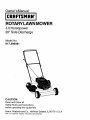
Owner's Manual
IROTARY
CRRFTSMRN°
IMOWER
LAWN
4.0 Horsepower
20" Side Discharge
Model No.
917.386081
CAUTION:
Read and follow all
Safety Rules and Instructions
before operating this equipment
Sears, Roebuck and Co., Hoffman Estates, IL 60179 U.S.A.
Visit our Craftsman website: www.sears.com/craftsman
Warranty .................................................
2
Safety Rules ........................................
2-4
Assembly / Pre-Operation
................... 4-8
Operation ...........................................
9-11
Maintenance
Schedule ........................
12
Maintenance
....................................
12-15
LIMITED
ONE YEAR WARRANTY
Product Specifications
..........................
13
Service and Adjustments ......................
15
Storage ............................................
16-17
Troubleshooting
..............................
17-18
Repair Parts .....................................
36-41
Sears Service .........................
Back Cover
ON CRAFTSMAN
POWER
MOWER
For one year from date of purchase, when this Craftsman Lawn Mower is maintained,
lubricated, and tuned up according to the operating and maintenance
instructions in
the owner's manual, Sears will repair free of charge any defect in material or workmanship.
If this Craftsman Lawn Mower is used for commercial
applies for only 90 days from the date of purchase.
or rental purposes,
this warranty
This Warranty does not cover:
• Expendable
items which become worn during normal use, such as rotary mower
blades, blade adapters, belts, air cleaners and spark plug.
• Repairs necessary because of operator abuse or negligence,
including bent
crankshafts
and the failure to maintain the equipment according to the instructions
contained in the owner's manual.
Warranty service is available by returning the Craftsman power mower to the nearest
Sears Service Center/Department
in the United States. This warranty applies only
while this product is used in the United States.
This Warranty gives you specific
vary from state to state.
SEARS,
ROEBUCKAND
legal rights, and you may also have other rights which
CO., D/817 WA, HOFFMAN
IMPORTANT:
This cutting machine
throwing objects. Failure to observe
serious injury or death.
ESTATES,
ILLINOIS
60179
is capable of amputating hands and feet and
the following safety instructions could result in
_,Look for this symbol to point out
important safety precautions.
It means
CAUTIONH!
BECOMEALERT!!!
YOUR
SAFETY IS INVOLVED.
_I, WARNING: Battery posts, terminals and
related accessories
contain lead and
lead compounds,
chemicals known to the
State of California to cause cancer and
birth defects or other reproductive
harm.
Wash hands after handling.
WARNING:
In order to prevent
accidental starting when setting up,
transporting,
adjusting or making repairs,
always disconnect spark plug wire and
place wire where it cannot contact spark
plug.
=0ACAUTION:
Muffler and other engine
parts become extremely hot during
operation and remain hot after engine
has stopped. To avoid severe burns on
contact, stay away from these areas.
_I,WARNING: Engine exhaust, some of
its constituents,
and certain vehicle
components
contain or emit chemicals
known to the State of California to cause
cancer and birth defects or other reproductive harm.
'_
2
.
I. GENERAL
OPERATION
• Read, understand, and follow all
instructions on the machine and in the
manual(s) before starting. Be thoroughly familiar with the controls and
the proper use of the machine before
starting.
• Do not put hands or feet near or under
rotating parts. Keep clear of the
discharge opening at all times.
• Only allow responsible
individuals,
who are familiar with the instructions,
to
operate the machine.
• Clear the area of objects such as
rocks, toys, wire, bones, sticks, etc.,
which could be picked up and thrown
by the blade.
• Be sure the area is clear of other
people before mowing. Stop machine if
anyone enters the area.
• Do not operate the mower when
barefoot or wearing open sandals.
Always wear substantial foot wear.
• Do not pu_l mower backwards unless
absolutely necessary. Always look
clown and behind before and while
moving backwards.
• Do not operate the mower without
proper guards, plates, grass catcher or
other safety protective devices in place.
• See manufacturer's
instructions for
proper operation and installation of
accessories.
DO NOT use accessories
that are not recommended
by the
manufacturer
of your mower, such as
de-thatcher blade attachments,
which
can be hazardous and damage the
mower.
• Stop the blade(s) when crossing gravel
drives, walks, or roads.
• Stop the engine (motor) whenever you
leave the equipment, before cleaning
the mower or unclogging the chute.
• Shut the engine (motor) off and wait
until the blade comes to complete stop
before removing grass catcher.
• Mow only in daylight or good artificial
light.
• Do not operate the machine while
under the influence of alcohol or drugs.
• Never operate machine in wet grass.
Always be sure of your footing: keep a
firm hold on the handle and walk; never
run.
• Disengage the self-propelled
mechanism or drive clutch on mowers so
equipped before starting the engine
(motor).
• If the equipment should start to vibrate
abnormally, stop the engine (motor)
and check immediately
for the cause.
Vibration is generally a warning of
trouble.
• Always wear safety goggles or safety
glasses with side shields when operating mower.
II. SLOPE
OPERATION
Slopes are a major factor related to slip
and fall accidents which can result in
severe injury. All slopes require extra
caution. If you feel uneasy on a slope, do
not mow it.
DO:
• Mow across the face of slopes: never
up and down. Exercise extreme caution
when changing direction on slopes.
• Remove obstacles such as rocks, tree
limbs, etc.
• Watch for holes, ruts, or bumps. Tall
grass can hide obstacles.
DO NOT:
• Do not trim near drop-offs, ditches or
embankments. The operator could lose
footing or balance.
• Do not trim excessively steep slopes.
• Do not mow on wet grass. Reduced
footing could cause slipping,
III. CHILDREN
Tragic accidents can occur if the operator
is not alert to the presence of children.
Children are often attracted to the
machine and the mowing activity. Never
assume that children will remain where
you last saw them.
• Keep children out of the trimming area
and under the watchful care of another
responsible
adult.
• Be alert and turn machine off if children
enter the area.
• Before and while walking backwards,
look behind and down for small
children.
• Never allow children to operate the
machine.
• Use extra care when approaching
blind
corners, shrubs, trees, or other objects
that may obscure vision.
3
IV. SERVICE
• Never tamper with safety devices.
Check their proper operation regularly.
• Keep machine free of grass, leaves, or
other debris build-up. Clean oil or fuel
spillage. Allow machine to cool before
storing.
• Stop and inspect the equipment if you
strike an object. Repair, if necessary,
before restarting.
• Never attempt to make wheel height
adjustments while the engine (motor) is
running.
• Grass catcher components are subject
to wear, damage, and deterioration,
which could expose moving parts or
allow objects to be thrown. Frequently
check components and replace with
manufacturer's recommended
parts,
when necessary.
• Mower blades are sharp and can cut.
Wrap the blade(s) or wear gloves, and
use extra caution when servicing them.
• Do not change the engine governor
setting or overspeed the engine.
• Use extra care in handling gasoline
and other fuels. They are flammable
and vapors are explosive,
-Use only an approved container.
-Never remove gas cap or add fuel
with the engine running. Allow
engine to cool before refueling. Do
not smoke,
-Never refuel the machine indoors.
- Never store the machine or fuel
container inside where there is an
open flame, such as a water heater.
• Never run a machine inside a closed
area.
• Never make adjustments
or repairs
with the engine (motor) running.
Disconnect the spark plug wire, and
keep the wire away from the plug to
prevent accidental starting.
• Keep nuts and bolts, especially blade
attachment bolts, tight and keep
equipment
in good condition.
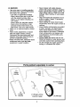
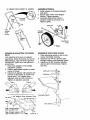
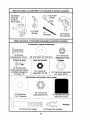
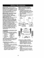
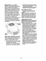
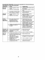
Parts packed separately in carton
(1) Discharge
Guard
(1)
Lowel
Handle
(1) Engine Zone
Control Cable
4
C4)Wheels
Parts Bag contents not shown full size
e(l) Rope
(4) Wheel
Height
Adjusters
(1) Upstop
Bracket
(2) Wing Nuts
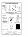
Parts Bag contents shown full size
Discharge
Guard
©
(2) Hex Bolts
Upstop
1/4-20
(2) Washers
3/4" Dia.
T
Rope Guide
Bracket
[1) Hex Washer Head
Self-tapping Screw
#10-24 x 1/2
j_
(1) Locknut
1/4-20
Wheel
\
(2) Locknuts
1/4-20
m
Wheels
(4) Flange
Locknuts
3/8-16
(4) Wheel Adjuster
Knobs
Adjusters
\
'\
z,
_. ......
/
(2) Washers 1-1/4" Dia.
(4) Locknuts
3/8-16
Handles
(2) Hairpin
5
Cotters
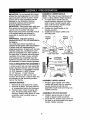
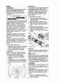
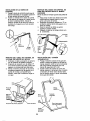
ASSEMBLE
LOWER HANDLE
NOTE: The holes in lower handle are off
ACAUTION:
Do not operate this mower
without the discharge guard or an entire
approved grass catcher in place. These
guards are for your protection and are
required by the American National
Standards Institute and Consumer
Products Safety Commission.
ACAUTION:
Disconnect spark plug wire
from spark plug and place wire where it
cannot come in contact with plug.
Read these instructions and this manual
in its entirety before you attempt to
assemble or operate your new lawn
mower.
IMPORTANT:
This lawn mower is
shipped WITHOUT OIL OR GASOLINE
in
the engine.
Your new lawn mower has been assembled at the factory with the exception
of those parts left unassembled
for
shipping purposes. All parts such as nuts,
washers, bolts, etc., necessary to complete the assembly have been placed in
the parts bag. To ensure safe and proper
operation of your lawn mower, all parts
and hardware you assemble must be
tightened securely. Use the correct tools
as necessary to ensure proper tightness.
TOOLS
REQUIRED
FOR
center to allow different height positions.
1. To install lower handle onto the
handle brackets squeeze the bottom
ends of lower handle towards each
other until the lower handle will slip
onto the mounting pins.
2. Position the lower handle in the
mowing position.
3. Install the two hairpin cotters onto
mounting pins.
Mowing
position
(_'_
Mowing
',
position
,
F_
/
;,
Hairpin
Mounting=
pin
LOW POSITION
HIGH POSITION
SQUEEZE
TO INSTALL
ASSEMBLY
A socket wrench set will make assembly
easier. Standard wrench sizes are listed.
(1) 5/16" Wrench (1) Adjustable Wrench
(1) 7/16" Wrench (1) 9/16" Wrench
(1) 1/2" Wrench
(1) 3/4" Wrench
When right hand or left hand is mentioned in this manual, it means when you
are standing in the operating position,
behind the handle.
Hairl:
ASSEMBLE
UNPACK CARTON
UPPER
HANDLE
1. Position upper handle over lower
handle with small hole for mounting
up-stop bracket to left side and
assemble handle bolts and wing nuts.
Tighten securely.
1. Remove all loose parts from carton.
2. Examine all items. Compare with list
of unassembled
parts and hardware.
3. Remove lawn mower housing with
care. Avoid touching blade under
housing. Always wear gloves or other
protection when working under or
lifting mower.
ASSEMBLE
2.
UPSTOP
BRACKET
Position upstop bracket on the left
inside of upper handle as shown.
3. Install the hex washer head screw into
the hole in up-stop bracket and upper
handle. Tighten securely.
6
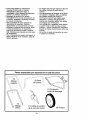
AS VIEWED FROM FRONT OF MOWER
ASSEMBLE
WHEELS
1.
Install wheels on threaded adjuster
axle arms.
2. Secure each wheel with flanged
Iocknut. Tighten securely.
3. Assemble adjustment knobs to
adjuster levers by pressing on or
tapping lightly.
Axle arm
\
Hex
washer
head
screw
\
Flanged
Iocknut
\
A_ustment
knob
Wheel
ASSEMBLE
DECK
ADJUSTERS
ASSEMBLE
TO MOWER
Look carefully at the four (4) adjuster
assemblies. Notice that there are two (2)
different types. Type I is for the right rear
and left front. Type II is for the right front
and left rear.
1. Place each adjuster in the middle
adjustment
position.
2. Position appropriate adjuster at each
corner of mower.
3. Install each adjuster with adjuster bolt
and tab in deck holes as shown and
secure with 1-1/4" washer (rear
adjusters only) and 3/8-16 Iocknut.
Tighten all adjusters securely.
DISCHARGE
1. Place discharge guard on top of lawn
mower discharge opening.
2. Install two (2) 1/4-20 x 3/4 hex bolts
through housing and discharge guard.
3. Install two (2) 3/4" diameter washers
and two (2) 1/4-20 Iocknuts. Tighten
securely.
Washers
Type I
1-1/4" Washer (Rear Adjusters Only)
Tabhole_f._
_ _-L_--_Locknuts))
)
Discharge guard
Hex
Type
(right
Type
(right
I heig
rear/left front)
_,.J_r'_'-__
II height adjuster _
front/left rear)----.,.._-_
I.
Tab hole 7
GUARD
INSTALL
CONTROL
BAR
ASSEMBLE
ENGINE ZONE CONTROL
CABLE TO UPPER HANDLE
1. Position control bar so flattened
section with hole is on opposite side
of handle as up-stop bracket.
2. Insert one end of control bar into
handle hole on inside of handle.
Carefully push in on opposite end of
control bar and insert into hole on
opposite side of handle.
Assemble cable to opposite side of upstop bracket.
1. Route cable below crossbar of lower
handle and up to control bar.
2. Hook "Z" bend fitting on inner wire into
hole in control bar.
3.
4.
Control bar
Attach cable fitting to upper handle as
shown.
Secure cable to lower handle with
wire tie.
Control
Upper
Upstop
racket
Up-stop bracket
ASSEMBLE
ENGINE
CABLE TO ENGINE
zone
control
cable
ZONE CONTROL
INSTALL
STARTER
ROPE
1. Put threaded end of rope guide
through hole in side of upper handle
above lower handle crossbar. Secure
with 1/4-20 Iocknut.
2. Hold control bar against upper handle
and slowly pull engine starter rope out
until rope will slip into loop of rope
guide.
1. Straighten cable and find the end with
the small plastic fitting.
2. Hook the "Z" bend fitting on inner wire
of cable into hole in brake arm of
engine.
3. Align the tapered end of the small
plastic fitting with the hole in the
mounting bracket and push in until
fitting snaps into place.
Rope
guide
Mounting
bracket
PUSH IN_
Lower handle
crossbar
arm
plastic fitting
Engine
starter rope
8
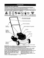
KNOW YOUR LAWN MOWER
READ THIS OWNER'S MANUAl_AND ALL SAFETY RULES BEFORE OPERATING YOUR
LAWN MOWER. Compare the illustrations with your lawn mower to familiarize yourself with
the location of various controls and adjustments. Save this manual for future reference.
These symbols may appear on your lawn mower or in literature
product. Learn and understand their meaning.
CAUTION
OR WARNING
ENGINE
ON
ENGINE
OFF
FAST
SLOW
CHOKE
FUEL
supplied
OIL
with the
DANGER, KEEP HANDS
AND FEET AWAY
-Operator presence control bar
Engine zone control cable
! nut
Starter
handle
Gasoline filler cap
Primer
Air filter
Engine oil plu
Muffler
Housing
Discharge
guard
Wheel adjuster (on each wheel)
IMPORTANT:
This lawn mower
is shipped
WITHOUT
OIL OR GASOLINE
in the engine.
MEETS CPSC SAFETY REQUIREMENTS
Sears rotary walk-behind power lawn mowers conform to the safety standards of the
American National Standards Institute and the U.S. Consumer Product Safety Commission. The blade turns when the engine is running.
Operator presence control bar - must be
held down to the handle to start the engine.
Release to stop the engine.
Starter handle - used for starting the engine.
Primer - pumps additional fuel from the
carburetor to the cylinder for use when
starting a cold engine.
9
BEFORE
The operationof any lawn
mowercan resultin foreign
objectsthrowninto the
eyes,which can resultin
severeeye damage.
Alwayswearsafetyglassesor eye
shieldswhile operatingyour lawn mower
or performingany adjustmentsor repairs.
We recommenda standardsafety
glassesor wide vision safetymaskworn
over spectacles.
ENGINE
Your lawnmower is shipped without oil in
the engine. For type and grade of oil to
use, see "ENGINE" in the Maintenance
section of this manual.
A CAUTION: DO NOT overfill engine with
oil, or it will smoke on startup.
1. Be sure lawnmower is level and area
around oil fill is clean.
2. Remove engine oil plug and fill to the
top slot in filler hole. Pour oil slowly.
NOTE: Allow oil to settle down into
engine for accurate reading.
3. Reinstall engine oil plug and tighten.
• Check oil level before each use. Add
oil if needed. Fill to top slot in filler
hole.
• Change the oil after every 25 hours of
operation or each season. You may
need to change the oil more often
under dusty, dirty conditions.
SPEED
ZONE CONTROL
ACAUTION:
Federal regulations require
an engine control to be installed on this
lawn mower in order to minimize the risk
of blade contact injury. Do not under any
circumstances attempt to defeat the
function of the operator control. The blade
turns when the engine is running.
• Your lawn mower is equipped with an
operator presence control bar which
requires the operator to be positioned
behind the lawn mower handle to start
and operate the lawn mower.
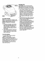
TO ADJUST CUTTING HEIGHT
Raise wheels for low cut and lower
wheels for high cut, adjust cutting height
to suit your requirements. Medium
position is best for most lawns.
• To change cutting height, squeeze
adjuster lever toward wheel. Move
wheel up or down to suit your requirements. Be sure all wheels are in the
same setting.
NOTE: Adjuster is properly positioned
when plate tab inserts into hole in lever.
Also, 9-position adjusters (if so equipped)
allow lever to be positioned between the
plate tabs.
LOWER WHEELS FOR HIGH CUT
_
Plate tal
RAISE WHEELS FOR LOW CUT
ENGINE
ADD OIL
The engine speed was set at the factory
for optimum performance. Speed is not
adjustable.
ENGINE
STARTING
ADD GASOLINE
• Fill fuel tank to bottom of tank filler
neck. Do not overfill. Use fresh, clean,
regular unleaded gasoline with a
minimum of 87 octane. Do not mix oil
with gasoline. Purchase fuel in
quantities that can be used within 30
days to assure fuel freshness.
A CAUTION:
Wipe off any spilled oil or
fuel. Do not store, spill or use gasoline
near an open flame.
A CAUTION:
Alcohol blended fuels
(called gasohol or using ethanol or
methanol) can attract moisture which
leads to separation and formation of
acids during storage. Acidic gas can
damage the fuel system of an engine
while in storage. To avoid engine
problems, the fuel system should be
emptied before storage of 30 days or
longer. Drain the gas tank, start the
engine and let it run until the fuel lines
and carburetor are empty. Use fresh fuel
next season. See Storage Instructions for
additional information. Never use engine
or carburetor cleaner products in the fuel
tank or permanent damage may occur.
Lever
10
Gasoline
filler cap
Engine
oil plug
TO START ENGINE
NOTE: Due to protective coatings on the
engine, a small amount of smoke may be
present during the initial use of the
product and should be considered
normal.
1. To start a cold engine, push primer
three (3) times before trying to start.
Use a firm push. This step is not
usually necessary when starting an
engine which has already run for a
few minutes.
2. Hold operator presence control bar
down to the handle and pull starter
handle quickly. Do not allow starter
rope to snap back.
MOWING TIPS
A CAUTION:
Do not use de-thatcher
blade attachments on your mower. Such
attachments
are hazardous, will damage
your mower and could void your warranty.
• Under certain conditions, such as very
tall grass, it may be necessary to raise
the height of cut to reduce pushing
effort and to keep from overloading the
engine and leaving clumps of grass
clippings. It may also be necessary to
reduce ground speed and/or run the
lawn mower over the area a second
time.
• For extremely heavy cutting, reduce the
width of cut by overlapping previously
cut path and mow slowly.
• For side discharge lawn mowers,
cutting in a counter-clockwise direction,
starting at the outside of the area to be
cut, spreads grass clippings more
evenly and puts less load on the
engine. To keep clippings off of
walkways, flower beds, etc., make the
first cuts in a clockwise direction.
• Keep top of engine around starter clear
and clean of grass clippings and chaff.
This will help engine air flow and
extend engine life.
TO STOP ENGINE
• To stop engine, release operator
presence control bar.
NOTE: In cooler weather it may be
necessary to r_peat priming steps. In
warmer weather over priming may cause
flooding and engine will not start. If you
do flood engine, wait a few minutes
before attempting to start and do not
repeat priming steps.
11
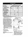
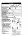
MAINTENANCE
SCHEDULE
AS YOU COMPLETE
/__°_
_o_X/_y
./'_'4
REGULARSERVICE
Chock for Loose Fasteners
SERVICE
"/,_0_"
/__'4
_X_y_
_
DATES
I_
Clean/Inspect Grass Catcher
(If Equipped)
I_
M
Clean Lawn Mower
O
(Power-Propened
Clean
Under DriveMowers)
Cover
Check ddvo belt/pulleys
if#
v'
_,_
RE Power-P ropelledMowers)
Check/Sharpen/Replace
if
Blade
I1 # 3
LubricationChart
Clean Battery/Recharge
tElectdc
Start Mowers !
I_
E
N
Check
Change Engine Oil
I_r.2
G
Clean Air Filter
_
i
Inspect Muffler
_'
Engine Oi! Level
N
Clean or Replace Spark Plug
E
Replace Air Filter Paper Cartridge
1234-
,/
V'
_#'
2
i/
t#12
Change more often when operating under a heavy load or in high ambient temperatures.
Sewice more often when operai_ng in dirty or dusty conditions,
Replace blades more often when mowing in sandy soil.
LUBRICATION
Charge 48 hour_ at et,,d of season.
CHART
(D Wheel adjuster
each wheel)
GENERALRECOMMENDA_ONS
The warranty on this lawn mower does not
cover items that have been subjected to
operator abuse or negligence. To receive full
value from the warranty, operator must
maintain mower as instructed in this manual.
Some adjustments will need to be made
periodically to properly maintain your uniL
All adjustments in the Service and Adjustments section of this manual should be
checked at least once each season.
• Once a year, replace the spark plug, clean
or replace air filter element and check
blade for wear. A new spark plug and
clean/new air filter element assure proper
air-fuel mixture and help your engine run
better and last longer.
• Follow the maintenance schedule in this
manual.
(!) Handle bracket mounting pins
BEFORE EACH USE
(_) Spray lubricant
• Check engine oil level.
• Check for loose fasteners.
(_) See "ENGINE"
(_ Brake
spring
bracket
Engine oil
LUBRICATION
Keep unit well lubricated (See "LUBRICATION
CHART").
12
in Maintenance
section.
IMPORTANT:
Do not oil or grease
plastic wheel bearings.
Viscous
lubricants will attract dust and dirt that
will shorten the life of the self-lubricating bearings.
If you feel they must be
lubricated, use only a dry, powdered
graphite type lubricant sparingly.
PRODUCT
SPECIFICATIONS
;erial Number:
Date of Purchase:
Gasoline
Capacity/Type:
1.25 Quarts
(Unleaded
Regular)
Oil Type (API-SF-SJ):
SAE 30 (above 32°F); SAE 5W-30
Oil Capacity:
20 Ounces
Spark Plug (Gap:
.045")
Blade Bolt Torque:
Champion
(below 32°F)
RJ19LM4
35-40 ft. Ibs.
• The model and serial numbers will be found on a decal on the rear of the mower
housing. Record both serial number and date of purchase in space provided above.
LAWN MOWER
Always observe safety rules when performing any maintenance.
TIRES
• Keep tires free of gasoline, oil, or insect
control chemicals which can harm rubber.
• Avoid stumps, stones, deep ruts, sharp
objects and other hazards that may cause
tire damage.
BLADE CARE
For best results, mower blade must be
kept sharp. Replace bent or damaged
blades.
TO REMOVE
BLADE
1. Disconnect spark plug wire from spark
plug and place wire where it cannot
come in contact with spark plug.
2. Turn lawn mower on its side. Make
sure air filter and carburetor are up.
3. Use a wood block between blade and
mower housing to prevent blade from
turning when removing blade bolt.
NOTE: Protect your hands with gloves
and/or wrap blade with heavy cloth.
4. Remove blade bolt by turning counterclockwise.
5. Remove blade and attaching hardware (bolt, lock washer and hardened
washer).
NOTE: Remove the blade adapter and
check the key inside hub of blade
adapter. The key must be in good condition to work properly. Replace adapter if
damaged.
TO REPLACE
(opposite sharp edge) is up toward
the engine.
4. Install the blade bolt with the lock
washer and hardened washer into
blade adapter and crankshaft.
5. Use block of wood between blade and
lawn mower housing and tighten the
blade bolt, turning clockwise.
• The recommended
tightening torque is
35-40 ft. Ibs.
IMPORTANT:
Blade bolt is grade 8 heat
treated.
TO SHARPEN BLADE
NOTE: We do not recommend sharpening blade - but if you do, be sure the
blade is balanced.
Care should be taken to keep the blade
balanced. An unbalanced blade will
cause eventual damage to lawn mower
or engine.
• The blade can be sharpened with a file
or on a grinding wheel. Do not attempt
to sharpen while on the mower.
• To check blade balance, drive a nail
into a beam or wall. Leave about one
inch of the straight nail exposed. Place
center hole of blade over the head of
the nail. If blade is balanced, it should
remain in a horizontal position. If either
end of the blade moves downward,
sharpen the heavy end until the blade
is balanced.
Blad,
Crankshaft
;way
Loc
BLADE
Blade
1. Position the blade adapter on the
engine crankshaft. Be sure key in
adapter and crankshaft keyway are
aligned.
2. Position blade on the blade adapter
aligning the two (2) holes in the blade
with the raised lugs on the adapter.
3. Be sure the trailing edge of blade
Blade.
bolt
Hard_
washer
13
shaft
Trailing edge
Blade adapter
ENGINE
AIR FILTER
LUBRICATION
Your engine will not run properly and may
be damaged by using a dirty air filter.
Replace the air filter every 100 hours of
operation or every season, whichever
occurs first. Service air cleaner more
often under dusty conditions. Do not
wash air filter.
Use only high quality detergent oil rated
with API service classification SF-SJ.
Select the oil's SAE viscosity grade
according to your expected operating
temperature.
SAE VISCOSITY
C
.3¢
-20
TEMPERATURE
.10
O
RANGE ANTICIPATED
GRADES
I0
BEFORE
TO CHANGE
1. Remove the air filter by turning
counterclockwise
to the stop and pull
away from collar.
2. Remove filter from inside of cover.
3. Clean the inside of the cover and the
collar to remove any dirt accumulation.
4. Insert new filter into cover.
5. Put air filter cover and filter into collar
aligning the tab with the slot.
6. Push in on cover and turn clockwise to
tighten.
40
NEXT OIL CHANGE
NOTE: Although multi-viscosity
oils
(5W30, 10W30 etc.) improve starting in
cold weather, these multi-viscosity oils
will result in increased oil consumption
when used above 32°F. Check your
engine oil level more frequently to avoid
possible engine damage from running
low on oil.
Collar
Change the oil after every 25 hours of
operation orat least once a year if the
lawn mower is not used for 25 hours in
one year.
Check the crankcase oil level before
starting the engine and after each five (5)
hours of continuous
use. Tighten oil plug
securely each time you check the oil
level.
TO CHANGE
ENGINE
AIR FILTER
Clip
TURN
COUNTERCLOCKWISE
TO
REMOVE
Slot
Air filter
OIL
Tab
Air filte
1. Disconnect spark plug wire from spark
plug and place wire where it cannot
come in contact with spark plug.
2. Be sure lawn mower is on level
surface.
NOTE: Oil will drain more freely when
warm. Catch oil in a suitable container.
3. Remove bottom oil drain plug.
4. After oil has drained completely,
replace oil drain plug and tighten
securely.
5. Fill engine with oil. (See "ADD OIL" in
the Operation section of this manual).
6. Reconnect spark plug wire to spark
plug.
TURN
CLOCK*
WISE TO TIGHTEN
MUFFLER
Inspect and replace corroded muffler as it
could create a fire hazard and/or damage.
SPARK
PLUG
Replace spark plugs at the beginning of
each mowing season or alter every 100
hours of operation, whichever occurs first.
Spark plug type and gap setting are
shown in "PRODUCT SPECIFICATIONS"
in Maintenance
section of this manual.
CLEANING
IMPORTANT:
For best performance,
kiip
mower housing free of built-grass and
trash. Clean the underside of your mower
after each use.
Drain plug
14
_CAUTION:
Disconnect spark plug wire
from spark plug and place wire where it
cannot come in contact with the spark
plug.
• Clean the underside of your lawn
mower by scraping to remove build-up
of grass and trash.
• Clean engine often to keep trash from
accumulating.
A clogged engine runs
hotter and shortens engine life.
• Keep finished surfaces and wheels free
of all gasoline, oil, etc.
• We do not recommend using a garden
hose to clean lawn mower unless the
electrical system, muffler, air filter and
carburetor are covered to keep water
out. Water in engine can result in
shortened engine life.
_;I,WARNING:
To avoid serious injury,
before performing any service or adjustments:
1. Release control bar and stop engine.
2. Make sure the blade and all moving
parts have completely stopped.
3. Disconnect spark plug wire from spark
plug and place where it cannot come
m contact with plug.
\
Lower
LAWN MOWER
TO ADJUST
cu'n'ING
ROTATE
HEIGHT
See "TO ADJUST CU3-1ING HEIGHT"
the Operation section of this manual.
in
Mowing
position
REAR DEFLECTOR
The rear deflector, attached between the
rear wheels of your mower, is provided to
minimize the possibility that objects will
be thrown out of the rear of the mower into
the operator's mowing position. If the
deflector becomes damaged, it should be
replaced.
DISCHARGE
GUARD
The discharge guard, attached to the
discharge opening of your lawn mower, is
provided to prevent the possibility of injury
resulting from bbjects being thrown out of
the discharge opening into the operator
mowing position. If the discharge guard
becomes damaged, it should be replaced.
TO ADJUST
HANDLE
Hairpin
Mounting pin
LOW POSITION
ENGINE
ENGINE
SPEED
Your engine speed has been factory set.
Do not attempt to increase engine speed
or it may result in personal injury. If you
believe that the engine is running too fast
or too slow, take your lawn mower to a
Sears or other qualified service center for
repair and adjustment.
CARBURETOR
The handle can be mounted in a high or
Your carburetor has a non-adjustable
low position. The mounting holes in the
fixed main jet for mixture control. If your
bottom of lower handle are off center for
engine does not operate properly due to
raising or lowering the handle.
suspected carburetor problems, take your
1. Remove upper handle and all parts
lawn mower to a Sears or other qualified
attached to lower handle.
service center for repair and/or adjustment.
2. Remove hairpin cotters from lower
handle bracket mounting pin.
IMPORTANT:
Never tamper with the
3. Squeeze lower handle in to remove it
engine governor, which is factory set for
from mounting pins.
proper engine speed. Overspeeding
the
4. Turn lower handle over to raise or
engine above the factory high speed
lower handle.
setting can be dangerous.
If you think the
5. Squeeze lower handle in and position
engine-governed
high speed needs
holes onto mounting pins on handle
adjusting, contact a Sears or other
bracket.
qualified service center, which has proper
6. Reassemble upper handle and all
equipment and experience to make any
parts removed from lower handle.
15necessary adjustments.
Immediatelyprepareyour lawn mowerfor
storageat the end of the seasonor if the
unit will not be usedfor 30 days or more.
LAWN
Operator
control bar
MOWER
When lawn mower is to be stored for a
period of time, clean it thoroughly, remove
all dirt, grease, leaves, etc, Store in a
clean, dry area.
1. Clean entire lawn mower (See
"CLEANING"
in the Maintenance
section of this manual).
2. Lubricate as shown in the Maintenance section of this manual.
3. Be sure that all nuts, bolts, screws,
and pins are securely fastened.
Inspect moving pads for damage,
breakage and wear. Replace if
necessary.
4. Touch up all rusted or chipped paint
surfaces; sand lightly before painting.
HANDLE
You can fold your lawn mower handle for
storage.
1. Squeeze the bottom ends of the lower
handle toward each other until the
lower handle clears the handle
bracket, then move handle forward.
2. Loosen upper handle mounting bolts
enough to allow upper handle to be
folded back.
IMPORTANT:
When folding the handle
for storage or transportation,
be sure to
fold the handle as shown or you may
damage the control cables.
• When setting up your handle from the
storage position, the lower handle will
automatically
lock into the mowing
position.
SQUEEZE
TO FOLD
Lower
FOLD
BACKWARD
Mowing
position
ENGINE
FUEL SYSTEM
IMPORTANT:
It is important to prevent
gum deposits from forming in essential
fuel system parts such as carburetor, fuel
filter, fuel hose, or tank during storage.
Also, alcohol blended fuels (called
gasohol or using ethanol or methanol)
can attract moisture which leads to
separation and formation of acids during
storage. Acidic gas can damage the fuel
system of an engine while in storage.
1. Drain the fuel tank.
2. Start the engine and let it run until the
fuel lines and carburetor are empty.
• Never use engine or carburetor cleaner
products in the fuel tank or permanent
damage may occur.
• Use fresh fuel next season.
NOTE: Fuel stabilizer is an acceptable
alternative in minimizing the formation of
fuel gum deposits during storage. Add
stabilizer to gasoline in fuel tank or
storage container. Always follow the mix
ratio found on stabilizer container. Run
engine at least 10 minutes after adding
stabilizer to allow the stabilizer to reach
the carburetor. Do not drain the gas tank
and carburetor if using fuel stabilizer.
ENGINEOIL
Drain oil (with engine warm) and replace
with clean engine oil. (See "ENGINE" in
the Maintenance section of this manual).
16
CYLINDER
• If possible, store your unit indoors and
cover it to protect it from dust and dirt.
• Cover your unit with a suitable protective cover that does not retain moisture.
Do not use plastic. Plastic cannot
breathe, which allows condensation
to
form and will cause your unit to rust.
IMPORTANT:
Never cover mower while
engine and exhaust areas are still warm.
_1,CAUTION:
Never store the lawn mower
with gasoline in the tank inside a building
where fumes may reach an open flame or
spark. Allow the engine to cool before
storing in any enclosure.
1.
2.
Remove spark plug.
Pour one ounce (29 ml) of oil through
spark plug hole into cylinder.
3. Pull starter handle slowly a few times
to distribute oil.
4. Replace with new spark plug.
OTHER
• Do not store gasoline from one season
to another.
• Replace your gasoline can if your can
starts to rust. Rust and/or dirt in your
gasoline will cause problems.
TROUBLESHOOTING
- See appropriate
to a Sears Service Center.
PROBLEM
Does not start
section in manual unless directed
CAUSE
CORRECTION
1. Dirty air filter.
1. Clean/replace air filter.
2. Out of fuel.
3. Stale fuel.
2. Fill fuel tank.
3. Drain tank and refill with
fresh, clean fuel.
4. Drain fuel tank and
carburetor and refill tank
with fresh gasoline.
5. Connect wire to plug.
4. Water in fuel.
5. Spark plug wire is
disconnected.
6. Bad spark plug.
7. Loose blade or broken
blade adapter.
8. Control bar in released
position.
9. Control bar defective.
10. Fuel valve lever (if so
equipped) in OFF position.
11 .Weak battery (if equipped).
12. Disconnected
battery
connector (if equipped).
Loss of power
.
*
Rear of lawn mower
housing or cutting blade
dragging in heavy grass.
Cutting too much grass.
3.
4.
Dirty air filter.
Buildup of grass, leaves,
and trash under mower.
5. Too much oil in engine.
6. Walking speed too fast.
17
6. Replace spark plug.
7. Tighten blade bolt or
replace blade adapter.
8. Depress control bar to
handle.
9. Replace control bar.
10.Turn fuel valve lever
to the ON position.
11.Charge
battery.
12.Connect battery to engine.
1. Set to "Higher
position.
Cut"
2. Set to "Higher Cut"
position.
3. Clean/replace
air filter.
4. Clean underside of mower
housing.
5. Check oil level.
6. Cut at slower walking speed.
TROUBLESHOOTING
:o a Sears
Service
- See
Center.
PROBLEM
Poor cutuneven
CAUSE
3.
Starter rope
hard to pull
heights
uneven.
Buildup of grass, leaves
and trash under mower,
1. Worn, bent or loose blade.
2.
.
in manual
unless
directed
CORRECTION
1. Worn, bent or loose blade.
2. Wheel
Excessive
vibration
appropriate section
Bent engine
crankshaft.
Engine flywheel brake is on
when control bar is released.
2.
Bent engine
3.
4.
Blade adapter broken.
Blade dragging in grass.
crankshaft.
1, Replace blade. Tighten
blade bolt.
2. Set all wheels at same
height.
3. Clean underside of
mower housing.
1.
Replace blade. Tighten
blade bolt.
2. Contact a Sears or other
qualified service center.
1.
Depress control bar to
upper handle before
pulling starter rope.
2. Contact a Sears or other
qualified service center.
3. Replace blade adapter.
4. Move lawn mower to cut
grass or to hard surface.
Grass catcher
notfilling
(Ifsoequipped)
1. Cutting height too low.
2. Lift on blade worn off.
3. Catcher not venting air.
1. Raise cutting height.
2. Replace blade.
3. Clean grass catcher.
Hard to push
1. Grass is too high or wheel
height is too low.
2. Rear of lawn mower
housing or cutting blade
dragging in grass.
3. Grass catcher too full.
4. Handle height position not
right for you.
1. Raise cutting height.
18
2.
Raise rear of lawn mower
housing one (1) setting
higher.
3. Empty grass catcher.
4. Adjust handle height to suit.
Garantt'a ........................................................ 19
Reglas de Seguridad ............................... 19-21
Montaje / Operaci6n ................................ 23-25
Operaci6n ................................................ 26-28
Mantenimiento ......................................... 29-32
Programa de Mantenimiento ......................... 29
Especificaciones del Producto ..................... 30
Servicio y Adjustes ....................................... 32
Almacenamiento ...................................... 33-34
Identificaci6n de problemas .................... 34-35
Panes de repuesto ................................. 36-41
Servicio Sears ................................ Contratapa
GARANTiA LIMITADA DE DOS AI_IOS PARA LA SEGADORA A MOTOR CRAFTSMAN
Por uno (1) aSo, a partir de la fecha de compra, cuando esta Segadora Craftsman se mantenga, lubrique
y afine segt_n las instrucdones para la operad6n y el mantenimiento en el manual del dueSo, Sears
reparar_ gratis todo defecto en el material y la mano de obra.
Si la Segadora Craftsman se usa para fines comerciales o de ardendo, esta garantfa s61ose aplica por
noventa (90) dfas a par'drde la fecha de compra.
Esta Garantfa no cubre:
• Artfculosque se desgastan durante el uso normaltales como las cuchillassegadoras rotatories, los
adaptadoresde la cuchilla,las correas,los filtros de alre y las bujfas.
• Reparaciones necesariasdebido al abuso o a la negligencia del operador,incluy_ndose a los
cigOeSalesdobladosy a la falta de mantenimiento del equiposeg6n las instruccionesque se incluyen
en el manualdel dueSo.
EL SERVIClO DE GARANTiA ESTA DISPONIBLE al devolver la segadora a motorCraftsmanal Centre/
Departmentode ServicioSears mas cercano en los Estados Unidos.Esta garantfase aplica solamente
mieetras el productoeste en uso en los EstadosUnities.
Esta Garantfa le otorga derechoslegales especificos, y puede que tambi_n tenga otrosderechos que
varfan de estado a estado.
Sears, Roebuckand Co., D/817WA, HoffmanEstates, IL 60179 USA
IMPORTANTE: Esta maquina cortadaora es capaz de amputar las manos y los manes y los
pies y de lanzar objetos. Si no se observan las instrucciones de seguridad siguientes se pueden
producir lesiones graves o la muerte.
_Busque este sfmbolo que seSala las
precauciones de seguridad de importancia.
Quiere decir - iiiATENCION!!!iiiESTE
ALERTO[!! SU SEGURIDAD ESTA
COMPROMETIDA.
_PRECAUCI6N:
El tubo de escape del
motor, algunos de sus constituyentes y
algunos componentes del vehiculo contienen
o desprenden productos quimicos conocides
en el Estado de California como causa de
cancer y defectos at nacimiento u otros da,Sos
reproductivos.
_ADVERTENCIA:
Siempre desconecte el
alambre de la bujfa y p6ngalo deride no pueda
entrar en contacto con la bujia, para evitar et
arranque pot accidente, durante la
preparaci6n, el transporte, el ajuste o cuando
se hacen reparaciones.
_PRECAUCI6N:
El silenciador y otras
piezas del motor Uegan a sre extremadamente
calientes durante la operaci6n y siguen siendo
calientes despu_s de que el motor haya
parado. Para evitar quemaduras severas,
permanezca lejos de estas &reas.
_ADVERTENClA:
Los bornes, terminales y
accesorios relativos de la baterfa contienen
plomo o compuestos de plomo, productos
qufmicos conocidos en el Estado de California
como causa de c_ncer y defectos al
nacimiento u otros daSos reproductivos. Lavar
las manos despu_s de manipularlos.
19
I. OPERACION
• Antes de empezar, debe familiarizarse
cornpletamente con los controlea y el usa
correcto de la maquina. Para esto, debe leer
y comprender todas ias instrucciones que
aparecen en la maquina yen los manuales
de operaci6n.
• No ponga las manos o los pies cerca o
debajo de las panes rotatorias. Mant_ngase
siempre lejos de la abertura de la descarga.
• Permita que so]amente las personas
responsables que estdn familiarizadas con
las instrucciones operen la m_quina.
• Despeje el drea de objetos tales coma
piedras, juguetes, atambres, huesos, palos,
etc. que pueden set recogidos y lanzados
par las cuchillas.
• Aseg_rese que el drea no se hallen
personas, antes de segar. Pare ]a mdquina
si alguien entra en el drea.
• No opere la maquina sin zapatos o con
sandalias abiertas. P6ngase siempra
zapatos s61idos.
• No tire de la segadora hacia atrds a menos
que sea absolutamente necosario. Mire
siempre hacia abajo y hacia detrds antes y
mientras que se mueve hacia atrds.
• No opere la segadora sin los respectivos
resguardos, las placas, el recogedor de
c_sped u otros aditamentos dise ados para
su protecci6n y seguridad.
• Refidrase alas instrucciones del fabricante
para el funcionamiento e instalaci6n de
acoesorios. NO utilizar accesorios no
recomendados par el constructor de la
segadora, coma dispositivos anti-paja de la
hoja, que pueden ser peligrosos y dar_arla
segadora.
• Detenga la cuchilla olas cuchillas cuando
cruce par calzadas, calles o caminos de
grava.
• Parar el motor cada vez que se abandona
el aparato, antes de limpiar la segadora o de
remover residuoa del tuba.
• Apagar el motor y esperar hasta que las
cuchillas estdn completamente paradas
antes de remover el receptor de hierba.
• Segar solamente con luz del dia o con una
buena luz artificial.
• No opere la mdquina bajo la influencia del
alcohol o de las drogas.
• Nunca opere la maquina cuando la hierba
estd mojada. Asegl3rese siempre de tener
buena tracci6n en sus pies; mantenga el
mango firmemente y camine; nunca corra.
• Desconectar el mecanismo de propulsi6n
aut6noma o el embrague de transmisi6n en
las segadoras que Io tienen antes de poner
en marcha el motor.
• Si el equipo empezara a vibrar de una
manera anormal, pare el motor y revise de
inmediato para averiguar la causa.
Generalmente la vibraci6n suele indicar que
existe alguna averfa.
• Siempre use gafas de seguridad o anteojos
con protecci6n lateral cuando opere la
segadora.
II. OPERACION
SABRE LAS CUESTAS
Los acoidentes ocurren con rods frecuencia
en las cuestas. Estos accidentes ocurren
debido a resbaladas o cafdas, las cuales
pueden resultar en graves lesiones. Operar la
recortadora en cuestas requiere mayor
concentraci6n. Si se siente inseguro en una
euesta, no la recorte.
HACER:
• Puede recortar a travds de la superficie de
la cuesta, nunca hacia arriba y hacia abajo.
Proceda con extrema precauci6n cuando
cambie de clirecci6n en las cuestas.
• Renueva todos los objetos extraSos, tales
coma guijarros, ramas, etc.
• Debe prestar atenci6n a hoyos, baches o
protuberancias. Recuerde que la hierba alta
puede esconder obst_iculos.
NO HACER"
• No recorte cerca de pendientes, zanjas o
terraplenes. El operador puede perder la
tracci6n en los pies o el equilibria.
• No recorte cuestas demasiado inclinadas.
• No recede en hierba mojada. La reducci6n
en la tracoi6n de la pisada puede causar
resbalones.
III. NllgOS
Se pueden produeir acoidentes tr_igicossi el
operador no presta atenci6n a la presencia de
los nif_os.A menudo, los ni£ios se sienten
atra{dos par la m&quina y par la actividad de la
siega. Nunca suponga que los nihos van a
permanecer en el mismo lugar donde los via
par Oltima vez.
• Mantenga a los niSos alejados del &rea de la
siega y bajo el cuidado estricto de otra
persona adulta responsable.
• Estd alerta y apague la mdquina si hay
niSos que entran al drea.
• Antes y cuando este retrocediendo, mire
hacia atr&s y hacia abajo para verificar si
hay niSos pequeSos.
• Nunca permita que los niSos operen la
mdquina.
• Tenga un cuidado extra cuando se acerque
a esquinas donde no hay visibilidad, a los
arbustos, drboles u arras objetos que
pueden interferir con su I{nea de visi6n.
IV. SERMICIO
• Tenga cuidado extra al manejar la gasolina
y los dem&s combustibles. Son inflamables
y los gases son explosivos.
- Use solamente un envase aprobado.
- Nunca remueva la tapa del dep6sito de
gasolina o agregue combustible con el
motor funcionando. Permita que el motor
se enfrie antes de volver a pone
combustible. No fume.
- Nunca vuelva a poner combustible en la
m&quina en recintos cerrados.
- Nunca almacene la m._quinao el envase
del combustible dentro de alg0n lugar en
donde haya una llama expuesta, tal coma
la del calentador de agua.
• Nunca haga funcionar una m&quina dentro
20
de un &rea cerrada.
• Nunca haga ajustes o reparaciones
mientras el motor est_ en marcha.
Desconecte el cable de la bujfa, y
rnantdngalo a cierta distancia de 6sta para
prevenir un arranque accidental.
• Mantenga las tuercas y los pemos,
especialmente los pemos del accesorio de
la cuchilla, apretados y mantenga el equipo
en buenas condiciones.
• Nunca manipule de forma indebida los
dispositivos de seguridad. Controle
regularmente su funcionamiento correcto.
• Mantenga la mdquina libre de hierba, hojas
u otras acumulaciones de desperdicio.
Limpie los derrames de aceite o combustible. Permita que la mdquina se enfrie antes
de almacenarla.
• Pare e inspeccione el equipo si le pega a un
objeto. Repdrelo, si es necesario, antes de
hacerlo arrancar.
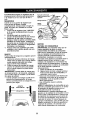
Partes empacadas
/
o
• En ningdn caso hay que regular la altura de
las ruedas mientras el motor estd en
marcha.
• Los componentes del receptor de la hierba
van sujetos a desgaste, daSos y deterioro,
que pueden exponer las partes en
movimiento o permitir que objetos sean
disparados. Controlar frecuentemente y
cuando sea necesario sustituir con partes
aconsejadas pot el fabricante.
• Las cuchitlas de la segadora estdn afiladas
y pueden cortar. Cubrir las hojas o Ilevar
guantes, y utilizar precauciones especiales
cuando se efect0a mantenimiento sobre las
mismas.
• No cambie el ajuste del regulador del motor
ni exceda su velocidad.
por separado
en la caja de cart6n
(1) Barrar/
de controlLL__
(1) Protecci6n
contra la descarga
(1)
Mango
inferior
(1) Cable de control
de la zona del motor
21
(4) Ruedas
Bolsa de partes, el contenido no se muestra en tama_o completo
(4) Ajustadores de
la altura
de la rueda
_'___ 1) Gufadel
(1) Puntal
de tope
(2) Tuercas
de mariposa
Bolsa de partes,
el contenido
Protecci6n
semuestra
contra
en tamaSo completo
la descarga
4#
(2) Pernos
hexagonales
1/4-20
Puntal
(2) Arandelas
Guia del cord6n
de tope
(1) Tornillo auto
enroscable
de cabeza
arandela hexagonal
#10-24 x 1/2
(1) Tuerca de
seguridad 1/4-20
_\Ajustadores
(2) Tuercas de
seguridad 1/4-20
3/4" Di&metro
"7
Ruedas
(4) Tuerca de seguridad
con collar 3/8-16
de la altura de la rueda
G
//
/'
(2) Arandelas
1-1/4" Di_metro
(4) Tuercas de
seguridad 3/8-16
(4) Manillas del ajustador de la rueda
Mangos
(2) Pernos
del mango
(2) Clavijas de horquilla
22
A_:kPRECAUCl6N: No haga funcionar su
segadora sin el desviador de recortes o sin el
recogedor de c_sped, apmbados, en su lugar.
Estos dispositivos de seguridad son para su
protecci6n y son requeridos pot el American
National Standards Institute y el U.S. Consumer Product Safety Commission.
_I_PRECAUCl6N:
Desconecte el cable de
bujfa de la bujfa y p6ngalo donde no pueda
ponerce en contacto con la bujfa.
Lea estas instrucciones y este manual
completamente antes de tratar de montar u
operar su segadora nueva.
IMPORTANTE: Este cortacesped viene SIN
ACEITE O GASOLINA en el motor.
Su segadora nueva ha eido montada en la
f&brica con la excepci6n de aquellas partes
que se dejaron sin montar por razones de
envfo. Todas las partes como las tuercas, las
arandelas, los pernos, etc., que son
necesarias para completar el montaje hart sido
colocadas en la bolsa de partes. Para
asegurarse que su segedora funcione en
forma segura y adecuada, todas las partes y
los artfculos de ferreterfa que se monten
tienen que ser apretados seguramente. Use
las herramientas correctas, como sea
necesario, para asegurar que se aprieten
adecuadamente.
HERRAMIENTAS
NECESARIAS
PARA
EL MONTAJE
Un juego de lave de tubo har& el ensamble
mas f&cil. Medidas estandartes est&n listadas.
(1) Llave de
(1) Llave de tubo
tubo de 5/16"
de ajuste
(1) Llave de
(1) Uave de tubo
tubo de 1/2"
de 3/4"
(1) Llave de tulSo (1) Llave de tubo
de 7/16"
de 9/16"
Cuando la mano derecha o la mano izquierda
est_n mencionadas en este manual, significa
que usted esta situado en la posici6n de
operador detras del mango.
DESEMPAQUETE EL CART6N
1. Remueva todas las partes sueltas de la
caja de cart6n.
2. Examine todos los artfculos. Comp_,relos
con la lista de partes no montadas y de los
artfculos de ferreterfa.
3. Remueva la caja de la segadora con
cuidado. Evite tocar la cuchilla debajo de la
caja. Siempre use guantes y otras
protecciones cuando trabaje debajo de la
segadora o cuando ta levante.
MONTAJE DEL MANGO INFERIOR
AVISO:Los agujems en el mango inferior
est_.n fuera del centro para permitir una
posicibn baja o alta.
1. Para instalar el mango inferior en los
puntales del mango apriete los extremos
inferiores del mango inferior entre sf, hasta
que el mango inferior se deslice en las
clavijas de montaje.
2. Ponga el mango infedor en la posici6n para
segar.
3. Instale las dos clavijas de horquilla en las
clavijas de montaje.
Posici6n
segar
Posicibn
parasegar
I_
Clavija
Clavi
montaje
POSICI(_N
BAJA
POSICI_)N ALTA
APRIETE
PARADOBLAR
Mangoin{edc
Clavij
Puntal
Clavijade horquilla ii
MONTAJE DEL MANGO SUPERIOR
1. Ponga el mango superior en el inferior con
el agujero pequefio para montar el puntal
de tope al lado derecho y monte los
pernos del mango y las tuercas de
mariposa. Apri_telos en forma segura.
MONTAJE DEL PUNTAL DE TOPE
2. Ponga el puntal de tope en el lado interior
derecho del mango superior, seg0n se
muestra.
3. Instale el tornillode cabeza de arandela
hexagonal en el agujero en el puntal de
tope yen el mango superior. Apri_telos en
forma segura.
23
VISTADESDE LA PARTEDELANTERADE LASEGADORA
MONTAJE DE LAS RUEDAS
1. Monte las ruedas en los brazos del eje
fileteado del ajustador.
2. Asegure cada rueda con la tuerca de
seguridad. Apriete en forma segura.
3. Monte las manillas de ajuste en las
palancas de ajustador presiondndolas o
golpe_.ndolas suavernente.
Brazo del eje
"_-
\
Tuerca_e_"_
\
Tomillode
cabezade
arandela
seguddad
\
hexagonal
Manilladeajuste
Rueda
MONTAJE DE LOS AJUSTADORES EN EL
CONJUNTO SEGADOR
Observe cuidadosamente los cuatro (4)
conjuntos del ajustador. Note que hay dos (2)
tipos distintos. El tipo I es para la parte trasera
derecha y la parte delantera izquierda. El Tipo
II es para la parte delantera derecha y la parte
trasera izquierda.
1. Ponga cada ajustador en la posici6n de
ajuste del medio.
2. Ponga el ajustador adecuado en cada
esquina de la segadora.
3. Instale cada ajustador con el perno del
ajustador y la oreja en los agujeros del
conjunto, segfin se muestra, y aseg_relos
con la arandela 1-1/4 di_metro
(ajustadores posteriores solamente) y la
tuerca de seguridad de 3/8-16. Apriete
todos los ajustadores en forma segura.
MONTAJE DE LA PROTECCION CONTRA
LA DESCARGA
1. Ponga la protecci6n contra la descarga en
la parte superior de la abertura de
descarga de la segadora.
2. Instale dos (2) pernos hexagonales de
1/4-20 x 3/4 a trav6s de la caja y
protecci6n contra la descarga.
3. Instale dos (2) arandelas de 3/4" de
didmetro y dos (2) tuercas de seguddad
de 1/4-20. Apridtelas en forma segura.
segundad
Type II
C_a
Arandela1-1/4di_.metro
(ajustadoresposterioressolamente)
Agujerodela
/
\
\
_.
....
Tuercade_
,
Proteccion
contra la
descarga
Pemos
Type I Ajustador de altura _--_(partstraseraderec.ha/
_ _'-_
:_ _
_
/
1
-partedelantera,
izquierda):_._-_,_._
_"
Aguj//e/r_
lype II Ajustador de altura_'-'* _ ---,_
(partedelanteraderechaJpartetraseraizquierda)
°rela 24
hexagonales
INSTALACION DE LA BARRA DE
CONTROL
1. Ponga la barra de controlde modo que la
secci6n aplanada con el agujero quede en
el lado opuesto del puntal de tope.
2. Inserte un extremo de la barra de control
en el agujero del mango en la parte interior
de dste. Cuidadosamente, empuje el
extremo opuesto de la barra de control e
insdrtela en el agujero en el lado opuesto
del mango.
MONTAJE DEL CABLE DE CONTROL DE
ZONA DEL MOTOR HAClA EL MANGO
SUPERIOR
Monte el cable en el lado opuesto del puntal de
tope.
1. Haga pasar el cable pot debajo de la barra
transversal del mango inferior y hacia
arriba a la barra de control
2. Enganche el accesorio doblado en "Z" en
el alambre interior dentro del agujero en la
barra de control.
3. Fixez le raccord du c_ble au guidon
superieur comme montr_.
4. Asegure el cable en el mango inferior con
la conexiones.
Punmlde
_pe
de control
Puntal
de tope
dela
zona
de
control
INSTALACION DEL CORDON
ARRANCADOR
1. Ponga el extremo roscado de la guia del
cord6n a travOs del agujero en el lado del
mango superior sobre la barra transversal
del mango inferior.Aseg_rela con una
tuema de seguridad de 1/4-20.
2. Sujete la barra de control en contra del
mango superior y lentamente tire el cord6n
arrancador del motor hacia afuera hasta
que se deslice dentro la parte redondeada
de la guia del cord6n.
MONTAJE DEL CABLE DE CONTROL DE
LA ZONA DEL MOTOR AL MOTOR
1. Enderece el cable y encuentre el extremo
con el accesorio de pldstico pequefio.
2. Enganche el accesodo con el doblez "_'
en el alambre interior del cable, dentre del
agujere, en el brazo del freno del motor.
3. Atinee el extremo ahusado del accesorio
de plastico pequefio con el agujero en el
puntal de montaje, y emp_jelo hacia
adentro, hasta que el accesorio caiga en
su lugar.
Puntalde
montaje
\
Gufa
del cordon
HACIA
ADENITIO
Accesorio
de plastico
pequefio
Brazo del freno
arrancador
del motor
25
FAMIUARICESE
CON SU SEGADORA
LEA ESTE MANUAL DEL DUENO Y LAS REGLAS DE SEGURIDAD ANTES DE OPARAR SU
SEGADORA. Compare las ilustraciones con su segadora para familiadzarse con la ubicacibn de los
diversos contfotes y ajustes. Guarde este manual para referencia en el futuro.
Estos simbolos pueden apareser sobre su segadora o en la literatura proporcionada con
el producto. Aprenda y comprenda sus significados.
ATTENCION 0
ADVERTENCIA
MOTOR
ENCENDIDO
MOTOR
APAGADO
R,_PIDO
LENTO
ESTRANGU
LACION
COMBUSTIBLE
ACEITE
PEUGRO, GUARDE LAS
MANOS Y LOS PiES LEJOS
Barra de control que exige
la presencia del operador
Control de zona del motor
,Teurca de mariposa
Cord6n
arrancador
Tapa del deposito de la gasolina
Cebador
Tapa del
deposito de
aceite con
varilla de nivel
Filtro de aire
Silenciador
Caja
Protecci6
contra la
descarga
Ajustador de la rueda (en cada rueda)
IMPORTANTE:
Este cortacdsped viene SIN ACEITE O GASOLINA en motor.
CUMPLE CON LOS REQUISITOS DE SEGURIDAD DE LA CPSC
Las segadoras a motor, que se conducen desde la parte de atrds, rotatorias, Sears, cumplen
con los estandares de seguridad del American National Standards Institute y de la U.S. Consumer Product Safety Commission. La cuchilla gira cuando el motor estd funcionando.
Barra de control que exlge la presencia del
necesita hacer arrancar un motor frio.
operador - tiene que sujetarseabajo, junto con el
Control de la aceleracion - se usa para
mango, para hacer arrancarel motor. Sudltela
hacer arrancar el motor y le permite
para parar el motor,
seleccionar las velocidades del motor ya sea
Cebador - bombea combustibleadicionaldesde el
R,&,PIDAo LENTA.
carburador al cilindro para uso cuando se
26
ANTES DE HACER ARRANCAR
EL
MOTOR
AGREGUE ACEITE
Su segadora fue enviada sin aceite en el
motor. Para el tipo y el grade del aceite a
utilizar, vea el "MOTOR" en la secci6n del
Mantenimiento de este manual.
_I_PRECAUCl6N: NO sobrellene el motor con
aceite, o fumard cuando Io valla a arrancar.
1. Aseg_rese que la segadora est6 nivelada
y que el drea alrededor del dep6sito de
aceite este limpia.
2. Remueva la tapa del dep6sitio de aceite
del motor y rellene hasta la cima de la
ranura en el agujero del rellenador. Vacie el
aceite lentamente. No Io Ilene demasiado.
AVISO: Permita que el aceite se aciente bien
en el motor para una lectura exacta.
3. Vuelva a instalar la tapa del dep6sitio de
aceite del motor y aprit61a.
• Revise el nivel de aceite antes de cada uso.
Agrague aceite si es necesqdo. Rellene
hasta la cima de la ranura en el agujero del
rellenador.
• Cambie el aceite despuds de 25 horas de
operaci6n o una vez por temporada. Puede
necesitar cambiar el aceite mds a menudo
cuando las condiciones son polvorosas o
sucias.
segadora puede hacer que
salten objetos extraSos dentro
La sus
operaci6n
cualquier
de
ojos, Iodeque
puede
producir daSos graves en _stos.
Siempro use anteojos de seguridad o
protecci6n para los ojos mientras opere su
segadora o cuando haga ajustes o
reparaciones. Recomendamos gafas o una
mascara de seguridad de visi6n amplia de
seguridad usada sobre las gafas.
COMO USAR SU SEGADORA
VELOCIDAD
DEL MOTOR
La velocidad del motor se estableci6 en la
f_,brica para un rendimiento 6ptimo. La
velocidad no se puede ajustar.
CONTROL DE ZONA DEL MOTOR
_I_PRECAUCI6N:
Las regulaciones federales
exigen que se instale un control para el motor
en esta segadora para reducir a un m[nimo el
riesgo de lesionarse debido al contacto con la
cuchilla. Por ning_n motivo trate de eliminar la
funci6n del control del operador. La cuchilla
gira cuando el motor estd funcionando.
• Su segadora viene equipada con una barra
de controles que exigen la presencia del
operador, Io que requiera que el operador
est_ detr_.sdel mango de la segadora para
hacerla arrancar y operarla.
AGREGUE GASOLINA
AVISO: Antes de rellenar el deposito de
carburante, remover y descartar los residuos
del tapon que se encuentran al interior del
deposito.
• Llene el estanque de combustible hasta la
parte infedor del cuello de reneno del
estanque de gasolina. No Io Ilene
demasiado. Use gasolina regular, sin
plomo, nueva y limpia con el minimo de 87
octanos. No mezcle el aceite con la
gasolina. Para asegurar que la gasolina
utilizada sea frasca compre estanques los
cuales puedan ser utilizados durante los
primeros 30 dias.
_PRECAUCI6N:
Limpie el aceite o el
combustible derramado. No almacene,
derrame o use gasolina cerca de una llama
expuesta.
PARA AJUSTAR LA ALTURA DE
CORTE
Levante las ruedas para el corte bajo y baje
las ruedas para el corte alto., ajuste la aitura
de corte para que se acomode a sus
requisitos. La posici6n del medio es la mejor
para la mayoria de los c_spedes.
• Para cambiar la altura de code, empuje la
palanca del ajustador hacia la rueda. Mueva
la rueda hacia arriba o hacia abajo de modo
que se acomode a sus requisitos.
Aseg6rase que todas las ruedas queden
igualmente ajustadas.
AVISO: El ajustador esta correctamente
colocado cuando tas orajas de la placa estan
insedadas en el agujero del mango. Tambi_n,
los ajustes de 9 posiciones (si equipado)
permiten que el mango pueda ser movido
entre las orajas de la placa.
PARA UN CORTE ALTO,
BAJE I_AS RUEDAS
Orejas de la placa
Mango
PAPA UN CORTE BAJO, LEVANTE !.AS RUEDAS
27
_PRECAUCI(_N"
Los combustibles
mezclados con alcohol (conocidos como
gasohol, o el uso de etanol o metanol) pueden
atraer la humedad, la que conduce a la
separaci6n y formacibn de _.cidos durante el
almacenamiento. La gasolina acidica puede
daSar el sistema del combustible de un motor
durante el almacenamiento. Para evitar los
problemas con el motor, se debe vaciar el
sistema del combustible antes de guardarlo
por un pefiodo de 30 dfas o m_s. Vacie el
estanquo del combustible, haga arrancar el
motor y h_galo funcionar basra que las lineas
del combustible y el carburador queden
vacios. La pr6xima temporada use
combustible nuevo. Vea las Instrucciones Para
El Almacenamiento para m_s informacibn.
Nunca use productos de limpieza para el
motor o para el carburador en el estanque del
combustible pues se pueden producir daSos
permanentes.
Tapa del
rellenadorde
gasolina
Tapa del
deposito
de aceite
PARA HACER ARRANCAR
EL MOTOR
AVISO: Debido alas capas protectoras del
motor, una cantidad pequeha de humo puede
estar presente durante el uso inicial del
producto y se debe considerar normal.
1. Para hacer arrancar un motor fdo, empuje
el cebador tres (3) veces antes de tratarlo.
Empuje firmemente. Este paso
normalmente no es necesario cuando se
hace arrancar un motor que ya ha estado
funcionando pot unos cuantos minutos.
2,
Sujete la barra de controles que exigen la
presencia del operador abajo en el mango
y tire el mango del arrancador
r._pidamente.No permita que el cord6n del
arrancador se devuelva abruptamente.
PARA PARAR EL MOTOR
• Para parar el motor, suelte la barra de
controles que exigen la presencia del
operador.
AVISO: En climas m&s frlos puede que sea
necesario repetir los pasos del cebado. En
climas m_s calurosos el cebar demasiado
puede producir el ahogo y el motor no va a
arrancar. Si se ahoga el motor espere unos
cuantos minutos antes de tratar de hacedo
arrancar y no repita los pasos del cebado.
CONSEJOS
PARA SEGAR
_PRECAUCI(_N:
No utilizar dispositivos antipaja de la hoja en la segadora ya que estos
accesorios son peligrosos, pueden daSar su
segadora y anutar su garantia.
• Bajo ciertas condiciones, tal como c_sped
muy alto, puede set necesario el elevar la
altura del corte para reducir el esfuerzo
necesario para empujar la segadora y para
evitar sobrecargar el motor, dejando
montones de recortes de cdsped. Puede
que sea necesario reduoir la velocidad del
recorddo y/o haga funcionar la segadora
sobre el drea por segunda vez.
• Para un corte muy pesado, reduzca el
ancho del corte pasando parcialmente pot
encima del lugar anteriormente cortado y
siegue lentamente.
• Si las segadoras de descarga lateral cortan
en una direcci6n contrada alas manillas del
reloj, si se empieza en la parte de afuera del
drea que se va a cortar, se repartirdn los
recortes del cdsped en forma m_.s pareja y
el motor se cargard menos. Para evitar que
los recortes caigan en los senderos, en las
flores, etc., haga los primeros cortes en la
direcci6n de las manillas del reloj.
• Mantenga la parte superior del motor,
alrededor del arrancador, despejada y sin
recortes de c_sped y paja. Esto ayudard el
flujo del aire del motor y extenderd,su
duraci6n.
28
PROGRAMA DE MANTENIMIENTOI.,__J_J
Revisar Sihay sujetadores sueltos
I_
Limpiar/inspecctonar el recogeclorde
S
c_sped
vieno equipado)
Lirnpiar (sl
la segadora
G
misi_n
con
poder de
propulsor)
Limpiar(segadoras
debajo de la
cubierta
la trans-
If
If
_
IfI_
_
If
poder
propulsor)
oD sadas
Revisar(se_adoras
las correascon
y las
poleas
impulRevisar o/afilar/camblar la cuchilla
R
li/
I/3
Tabla de lubdcaci6n
Limpiar la baterfa,'recargar
(segadoras con arranque eldctdco)
V/
M
Cambiar
elnivel
aceite
motor
Revisar el
deldel
aceite
1411,2
T
Inspeccionar el silenciador
Limpiar el filtro de aire
Umpiar o/carnbiar la bujia
_2
R
If
Cambiar
de airo el caducho de papel del fiitro
I/'4
V'2
1 - Carnbiar m_s a menudo cuando se opere bajo carga pesada o en ambientes con alias temperaturas,
2 ° O&t SBP/_O 133
_LRa mertudo cual3do $e opere _n Condiciones $ucia$ o polvorosa$,
3 - Cambie las cuchillas m_$ a menudo c_ando siegue en terreno arenoso.
TABLA DE LUBRICACII3N
4" Cargar po, 48 horas al fin de la tempomde.
RECOMENDACIONES
GENERALES
La garanfiade esta segadora no cubre los
artfculosque ban estado sujetosal abuso o a la
negligenciadel operador.Para mcibirtodoel valor
de la garant|a,el operadertiene que mantenerla
segadora seg_n las instruccionesdescritasen
este manual.
Hay algunosajustes que se tienen que hacer en
forma peri6dicapara poder mantener su unidad
adecuadamente.
Todos los ajustes en la secci6nde Servicioy
Ajustesde este manual tienenque ser revisados
por Io menos un vez por cada temporade.
• Una vez al aRo,cambie la bujia, limpieo cambie
el elementodel filtrode aire y revisesi la cuchilla
estd desgastade.Una bujia nueva y un
elementodel flltrode aire limpio/nuevoaseguran
la mezcla de aim-combustibleadecuada y
ayuden a que su motorfuncione rnejory que
dure m&s.
• Siga el programa de mantenimiento en este
manual.
(_) Aceite del motor
(_) Puntal
de resorte
del freno
(_) Ajustador
de la rueda
(!) Clavija de montaje del puntal del mango
Rocle el lubrlcante
ANTES DE CADA USO
• Reviseel niveldel aceite del motor.
• Revise si hay sujetadoressueltos.
@ Vea
LUBRICACION
Mantenga la unidad bien lubricada (yea ia "I'ABLA
DE LUBRICAClON").
29
"MOTOR"
en la secclon de Mantenirniento
IMPORTANTE: No aceite o engrase los
rodamientos de la rueda de plastico. Los
lubricantes viscosos atearan polvo y
mugre, Io acortara la duracion de los
rodamientos autolubricantes. Si cree que
tienen que lubricarse, use Iosamente un
lubricante tipo crafito, de polvo seco, en
forma moderada.
ESPECIFICAClONES
DEL PRODUCTO
NLimero de Serie:
Fecha de Compra:
Capacidad
y Tipo de Gasolina:
Tipo de Aceite (API-SF-SJ):
Capacidad
de Aceite:
Bujfa (Abertura:
.045")
TorsiSn del Perno de la Cuchilla:
1.25 Cuartos
(Regular
sin Plomo)
SAE 30 (sobre 32°F);SAE
20 Onzas
5W-30
(debajo
32°F)
Champion
RJ19LM4
35-40 ft. Ibs.
El n_mero del nodelo y el de serie se encuentran en la calcomania adjunta a la parte trasera
de la caja de la segadora. Debe registrar tanto el n_mero de serie come la fecha de compra y
mantengalos en un lugar seguro para refencia en el futuro.
SEGADORA
Siempre observe las reglas de seguridad
cuando haga el mantenimiento.
LLANTAS
• Mantenga las Ilantas sin gasolina, aceite o
substancias qufmicas para control de
insectos que pueden dafiar la goma.
• Evite los tocones, las piedras, las grietas
profundas, los objetos afilados y otros
peligros que pueden dahar a las Ilantas.
CUIDADO DE LA CUCHILLA
Para obtener los mejores resultados, la
cuchilla de la segadora tienen que mantenerse
afilada. Cambie la cuchilla doblada o daSada.
PARA REMOVER LA CUCHILLA
1. Desconecte el alambre de la buj_ay
p6ngalo en donde no pueda entrar en
contacto con _sta.
2. Haga descansar la segadora en su lado.
AsegSrese que el filtro de aire y que el
carburador queden mirando hacia ardba.
3. Use un bloque de madera entre la euchilla
y la caja de la segadora para evitar que la
cuchilla gire cuando se le quite el pemo.
AVISO: Proteja sus manos con guantes y/o
envuelva la cuchilla con una tela gruesa.
4. Remueva el perno de la cuchilia gir&ndolo
en el sentido contrario en que giran las
manillas del reloj.
5. Remueva la cuchilla y los articulos de
ferreteria adjuntadores (el perno, la
arandela de seguridad y la arandela
endurecida).
AVISO: Remueva el adaptador de la cuchilla y
revise el cubo interior de la ranura del
adaptador de la cuchilla. La ranura tiene que
estar en buenas condiciones para que
funcione en forma adecuada. Cambie el
adaptador siesta, dahado.
PARA CAMBIAR LA CUCHILLA
1. Ponga el adaptador de la cuchilla en el
cigue£1aldel motor. Aseg_rese que la
ranura del adaptador y que el chavetero
del cigueSal estOn alineados.
2. Ponga la cuchilla en el adaptador de dsta
alineando los dos (2) agujeros en la
cuchilla con las salientes elevadas en el
adaptador.
3. Asegerese de que el borde de salida de la
cuchilla (opuesto al borde afilado) est6
hacia arriba hacia el motor.
4. Instale el perno de la cechilla con la
arandela de seguddad y la arandela
endurecida en el adaptador de la cuchilla y
el cigue_al.
5. Use un bloque de madera entre la cuchilla
y la caja de la segadora y apriete el pemo
de la cuchilla gir&ndoloen el sentido en
que giran las manillas del reloj.
• La torsibn para apretar recomendada es de
35 - 40 pies libras.
IMPORTANTE" El pemo de la cuchilla es
clase 8 tratado a calo.
PARA AFILAR LA CUCHILLA
AVISO: No recomendamos el afilar la cuchilla
- pero si Io hace, aseg_rese de que quede
balanceada.
Se tiene que tener cuidado de mantenerla
balanceada. Una cuchilla que no est&
balanceada va a producir eventualmente daSo
en la segadora o en el motor.
• La cuchilla puede afilarse con una lima o en
una rueda rectificadora. No trate de afilarla
mientras se encuentra en la segadora.
• Para revisar el balance de la cuchilla, clave
un clavo en una viga o en la pared. Deje
alrededor de una pulgada de un clavo recto
expuesto. Ponga el agujero central de la
cuchilla sobre la cabeza del clavo. Si la
cuchilla est& balanceada debe permanecer
en la posici6n horizontal. Si cealquiera de
los extremes de la cuchilla se mueve hacia
abajo, afile el extremo pesado hasta que
_sta quede balanceada.
Ada
Cuchina
Pemo Arandela
de la endurecida
30cuchilla
Borde de salida
Cigu_Dnal
Adaptador de la cuchilla
MOTOR
LUBRICACI(_N
Use solamenteaceite de detergente de alta
calided clasiflcadocon la clasiflcaci6nSF-SJ de
servicio API. Seleccionela calidadde viscosidad
SAE seg0n su temperaturade operaci6n
esperada.
CALIDADES
DE VISCOSIOAD
DE SAE
AVISO: A pesar de que los aceitesde
multJviscosidad(5W30, 10W30, etc.) mejoran el
arranqueen climafrio, estosaceites de
multiviscosidad
van ha aumantarel consumode
aceite cuando se usan en temperaturas sebre 32=
F. Revise el niveldel aceitedel motorm_is a
menudo, para evitarun posibledar3oen el motor,
debidoa que no tiene suficienteaceite.
Cambie el aceitedespu_sde 25 horasde
operaci6no por Io menos una vez al aSo si la
segadora se utilizamenos 25 horasel afro.
Reviseel niveldel aceitedel c_ler antes de
arrancar el motor y despu#.sde cada cinco (5)
horasde use continuado. Aprieteel tapbndel
aceiteen forma segura cada vez que revise el
niveldel aceite.
PARA CAMBIAR EL ACEITE DEL MOTOR
FILTRO DE AIRE
Su motor puede sufrir aver{as y funcionar de
manera incorrecta con un filtro del aire sucio.
Sustituir el papel del cartucho una vez al aSo o
tras 100 horas de funcionamiento, rods a
menudo si se utiliza en condieiones de
suciedad y polvo particulares. No lave el filtre
de aire.
PARA CAMBIAR EL FILTRO DE AIRE
1. Remueva el filtro de aire gir&ndoloen el
sentido contrario en que giran las manillas
del reloj, hasta el tope, y ret{relodel collar.
2. Remueva el filtro de la parte interior de la
cubierta.
3. Limpie la parte interior de la cubierta y el
collar para remover toda acumulaci6n de
mugre.
4. Inserte el filtro nuevo en la cubierta.
5. Ponga la cubierta del filtro de aire dentro
del collar alineando la oreja con la ranura.
6. Empuje la cubierta hacia adentro y girela
ea el sentido de las manillas del reloj para
apretarla.
Conar
Abrazadera
GIRE EN EL SENTIDO
CONTRARIO A LAS
MANILLAS
DEL
RELOJ
PARA
REMOVER
Ranum
1. Desconecte el alambre de la buj[a y
pSngalo de modo que no pueda entrar en
contacto con 6sta.
2. AsegQrese que la segadora est6 en una
superficie nivelada.
AVISO: El aceite se drenar& m&s f&cilmente si
esta caliente. Recoja el aceite en un envase
adecuado.
3. Remueva el tap6n de drenaje del dep6sito
de aceite de la parte inferior.
4. Despu_s de-que el aceite se haya drenado
completamente, vuelva a poner el tap6n de
drenaje del dep6sito de aceite en su lugar
y apri6telo en forma segura.
5. Rellene el motor con aceite. (Vea "PARA
AGREGAR EL ACEITE" en Ia secci6n de
Operacibn de este manual.)
6. VueIva a conectar el alambre de la bujia a
6sta.
Filtro de aire
GIRE EN EL
Oreja
I_ASMANILLAS
Cubierta del filtro de aire DEL RELOJ PARAAPRETAR
SILENClADOR
Inspeccione y cambie el silenciador si est&
corroido puede producir un peligro de incendio
y/o daSo.
BUJiA
Cambie el buj{a al comienzo de cada
temporada de siega o despu_s de cada 100
horas de operacibn, Io que suceda pdmero. El
tipo de bujia y el ajuste de la abertura
aparecen en "ESPECIFICACIONES DEL
PRODUCTO" en la secci6n de Mantenimiento
de este manual.
LIMPIEZA
IMPORTANTE: Para obtener el mejor
rendimiento, mantenga la caja de la segadora
sin acumulacion de cesped y basura. Limpin la
parte de abajo de su segadora despues de
cada use.
_LPRECAUCI6N: Desconecte el alambre de
la buj{a y pbngalo en donde no pueda entrar
en contacto con _sta.
• Limpie la parte inferior de su segadora
raspandola para remover la acumulacibn de
c_sped y basura.
Tapon de drenaje
31
= Limpie el motor a menudo para evitar que
se acumule la basura. Un motor tapado
funciona m_s caliente y se acorta su
duracibn.
• Mantenga las superficies pulidas y las
ruedas sin gasolina, aceite, etc.
• No recomendamos el uso de una manguera
de jardl'n para limpiar la segadora a menos
que el sistema el_ctrico, el silenciador, el
filtro de aire y el carburador est6n tapados
para evitar que les entre el agua. El agua en
el motor puede acortar la duraci6n de 6ste.
_,ADVERTENClA:
Para evitar lesi6nes
serias, antes de dar calquier servico o de
hacer ajustes:
1. Suelte la barra de control y pare el motor.
2. AsegSrese que la cuchilla y que todas las
partes movibles se hayan detenido
completamente.
3. Desconecte el alambre de la bujfa y
p6ngalo en donde no pueda entrar en
contacto con esta.
Mango
SEGADORA
PARA AJUSTAR LA ALTURA DE CORTF
Vea =PARA AJUSTAR LA ALTURA DE
CORTE" en la secci6n de Operaci6n de este
manual.
'_:'-'I
inferior_'GIRAF
Posici6n
arasegar
d""_
=
Posici6n
i"v_
parasegar /
I
DESVIADOR TRASERO
Se proporciona un deeviador trasero, adjunto
entre las ruedas traseras de su segadora,
para reducir a un minimo la posibilidad que
objetos sean lanzados hacia afuera de la parte
trasera de la segadora, en la posici6n en
donde se encuentra el operador. Si se da=Sael
desviador debe cambiarse.
f
PROTECCION CONTRA LA DESCARGA
Se proporciona una protecci6n contra la
descarga, adjunta a la abertura de descarga
de su segadora, para evitar la posibilidad que
objetos sean lanzados hacia afuera de la
abertura de descarga, en la posici6n en donde
se encuentra el operador. Si se daSa la
protecci6n contra la descarga debe
cambiarse.
PARA AJUSTAR EL MANGO
El mango puede ser montado a una posici6n
alta o baja. Los agujeros de montaje en el
mango inferior estdn fuera del centro para
levantar y bajar el mango.
1. Remueva el mango superior y todas las
partes atadas al mango inferior.
2. Remueva las clavijas de horquilla de la
clavija de montaje del puntal del mango.
3. Apreite el mango inferior hacia dentro para
removerlo de las clavijas de montaje.
4. Gire el mango inferior pot encima para
levantar o bajar el mango.
5. Vuelva a montar las clavijas de horquilfa
por encima de las clavijas de montaje.
6. Vuelva a montar el mango superior y todas
las partes removidas del mango inferior.
32
Clavijade
_del mango _
montaje L====_==
POSICI_)NBAJA
POSICIONALTt
MOTOR
VELOCIDAD DEL MOTOR
La velocidad del motor ha sido ajustada en la
fabrica. No trate de aumentar la velocidad del
motor pues se pueden producir lesiones
personales. Si cree que el motor esta
funcionando demasiado rdpido o demasiado
lento, Ileve su segadora a mas con su centre
de servicio Sears o con un otro centro de
servicio cualificado.
CARBURADOR
Su carburador tiene un chorro principal fijo no
ajustable para controlar la mezcla. Si su motor
no est_ funcionando en forma adecuada
debido a problemas que se sospecha vienen
del carburador, Ileve su segadora a contacto
con su centro de servicio Sears o con un otro
centro de servicio cualificado para repararla y/
o ajustarla.
IMPORTANTE: Nunca manipule el regulador
del motor, el que ha sido ajustado en la f&brica
para la velocidad del motor adecuada. Puede
ser peligroso hacer funcionar el motor a una
velocidad per sobre el ajuste de alta velocidad
de la f,_brica. Si cree que la velocidad alta
regulada del motor necesita ajuste,contacto
con su centro de servicio Sears o con un otro
centro de servicio cualificado, el que cuenta
con el equipo adecuado y la experiencia para
hacer los ajustes necesarios.
Inmediatamente prepare su segadora para el
almacenamiento al final de cada temporada o
si la unidad no se va a usar por 30 dias o
m&s.
SEGADORA
Cuando se va a guardar la segadora por
cierto pefiodo de tiempo, limpiela
cuidadosamente, remueva toda la mugre, la
grasa, las hojas, etc. Gudrdela en un _.rea
limpia y seca.
1, Limpie toda la segadora (Vea "LIMPIEZA"
en la secci6n de Mantenimiento de este
manual).
2. Lubfiquela segL_nse muestra en la
secci6n de Mantenimiento de este manual.
3. Aseg_rese de que todas las tuercas y
clavijas y todos los pernos y tomillos est_n
apretados en forma segura. Inspeccione
las partes que se mueven para verificar si
estdn dafiadas, quebradas o desgastadas.
C.4mbielas si es necesario.
4. Retoque todas las superficies que est_n
oxidadas o con la pintura picada; use una
tija antes de pintar.
MANGO
Puede doblar el mango de su segadora para el
almacenamiento.
1. Apriete los extremos inferiores del mango
inferior entre sf hasta que el mango inferior
quede separado del puntal del mango,
luego mu_valo hacia adelante.
2. Suelte los pernos de montaje del mango
superior Io suficiente como para permitir
que el mango superior se pueda doblar
hacia atrds.
IMPORTANTE: Cuando doble el mango para
el almacenamiento o el transporte, aseg(_rese
que Io doble segdn se muestra o purde daSar
los cables de control.
• Cuando prepare sus mangos a partir de la
posiciSn de almacenamiento, et mango
inferior automaticamente se asegurard en la
posiciSn para segar.
APRIETE
PAPA DOBLAR
Mango
Barrade controlque
_,/:_
i,.
exigela presenciadel//_,/)
DOBLAR ._,2_
operador
//// HACIA
/Y
Mangosupedorf
/II/
inferior -................_\
__:L.. *'"
__
o_.
PARA
,7
4?
-'., /;F-"_'_,/
;,,k //%
V_ 'Y \
)_
/
>)
1
.
ARRAS
parasegar
MOTOR
SISTEMA DE COMBUSTIBLE
IMPORTANTE: Es importante evitar que se
formen dep6sitos de goma en parfes
fundamentales del sistema de combustible
tales como el carburador, el filtro del combustible, la manguera del combustible o en el
estanque durante el almacenamiento, Los
combustibles mezclados con alcohol
(conocido como gasohol o que tienen etanol o
metanol) pueden atraer humedad, Io que
conduce a la separacion y a la formacion de
acidos durante el almacenamiento. La gasolina
acidica puede dafiar el sistema de combustible
de un motor durente el periodo de
almacenamiento.
1. Drene el estanque de combustible.
2. Haga arrancar el motor y d_jelo funcionar
hasta que las lineas del combustible y et
carburador est_n vacios.
• Nunca use los productos para limpieza del
carburador o del motor en el estanque de
combustible pues se pueden producir
dafios permanentes.
• Use combustible nuevo la pr6xima
temporada.
AVISO: El estabilizador de combustible es una
alternativa aceptable para reducir a un mlnimo
la tormaciSn de depSsitos de goma en el
combustible durante el periodo de
almacenamiento, Agregue estabilizador a la
gesolina en el estanque de combustible o en el
envase para el almacenamiento, Siempre siga
la proporcibn de mezcla que se encuentra en
el envase del estabilizador. Haga funcionar el
motor por Io menos 10 minutos despu_s de
agregar el estabilizador, para permitir que este
Ilegue al carburador. No drene la gasolina del
estanque de gasolina y el carburador si se
esta usando estabilizador de combustible.
33
ACEITE DEL MOTOR
Drene el aceite (con el motor caliente) y
cdmbielo con aceite de motor limpio. (Vea
=MOTOR" en la secci6n de Mantenimiento de
este manual.)
• Cambie el envase de la gasolina si se
empieza a oxidar. La oxidaci6n y/o la mugre
en su gasolina producir&n problemas.
• Si es posible, guarde su unidad en un
recinto cerrado y c5brala para protegerla
contra el polvo y la mugre.
• Cubra su unidad con un forro protector
adecuado que no retenga la humedad. No
use pldstico. El pl&stico no puede respirar, Io
que permite la formaci6n de condensaci6n,
Io que producir_l la oxidaci6n de su unidad.
IMPORTANTE: Nunca cubra la segadora
mientras el motor y las areas de escape to
davia estan calientes.
ClLINDRO
1. Remueva la bujia.
2. Vacie 29 ml (una onza) de aceite a tray,s
del agujero de la bujfa en el cilindro.
3. Tire la manilla de arranque lentamente
unas cuantas veces para distribuir el
aceite.
4. Cambie por una bujfa nueva.
,_,PRECAUCI(_N: Nunca almacene ta
segadora con gasolina en el estanque dentro
de un edificio en donde los gases pueden
alcanzar una llama expuesta o una chispa.
Permita que se enfrfe el motor antes de almacenarla en alg_n recinto cerrado.
OTROS
• No guarde la gasolina de una temporada a
la otra.
SOLUClON DE PROBLEMAS
- Vea la secci6n
est6 dirigido
un centro de servlco Sears.
PROBLEMA
No arranca
apropiada
CAUSA
amenos que
CORRECCION
1. Filtro de aire sucio.
2. Sin combustible.
3. Combustible rancio.
4. Agua en el combustible.
5. Alambre de la bujfa desconectado.
6. Bujfa mala.
7. Cuchilla suelta o adaptador
de la cuchilla quebrado.
8. Barra de control en la
posici6n suelta.
9. Barra de control defectuosa.
10. Vdlvula del combustible (si equipada) estd en la posici6n OFF.
11. Bateria d_bi (si equipada).
12. Desconecte el conector
de la bateria (si equipada).
Falta de
fuerza
en el manual
1. Cuchilla desgastada, doblada
o suelta.
2. Altura de tas ruedas dispareja.
3. Velocidad del motor lenta.
4. Acumulaci6n de c_sped, hojas o
basura debajo de la segadora.
5. Demasiado aceite en motor.
6. Velocidad de recorrido
demasiado r_pida.
34
1. Limpie/cambie el filtro de aire.
2. Llene el estanque de combustible.
3. Drene el estanque y vuelva a
Ilenarlo con combustible limpio
y nuevo.
4. Drene el estanque de combustible
y el carburador y vuelva a Ilenar el
estanque con gasolina nueva.
5. Conecte el alambre a la bujia.
6. Cambie la bujfa.
7. Apriete el pemo de la cuchilla
cambie el adaptador de la cuchilla.
8. Presione la barra de control
hacia el mango.
9. Cambie la barra de control.
10. Gim a la v&lvula del combustible
a la posici6n ON.
11. Cague la baterfa.
12. Conecte la bateda al motor.
1. Ajuste a la posici6n de
"Code m&s alto."
2. Ajuste a la posici6n de
"Code mds alto."
3. Limpie/cambie el filtro de aire.
4. Limpie la parle inferior de la
caja de la segadora.
5. Revise el nivel del aceite.
6. Code a una velocidad de
recorrido rods lenta.
SOLUCI(3N DE PROBLEMAS - Vea la secci6n
estd dirigido
un centro de servico Sears.
PROBLEMA
Mal codedisparejo
apropiada
CAUSA
en el manual amenos
que
CORRECCI(_N
1. Cuchilla desgastada, doblada
o suelta,
2. AItura de las ruedas dispareja.
3. Acumulaci6n de c6sped, hojas o
basura debajo de la segadora,
Vibracidn
excesiva
1. Cuchilla desgastada, doblada
o suelta,
2. Ciguefial del motor doblado.
Cord6n
arrancador
dificil de tirar
1. El freno del volante del motor
1. Cambie la cuchilla. Apriete el perno
de la cuchilla.
2. Ajuste todas las ruedas a la misma
altura.
3. Limpie la parte inferior de la
caja de la segadora.
1. Cambie la cuchilla. Apriete el
perno de la cuchilla,
2. P6ngase en contacto con su centro
de servicio Sears o con un otro
centro de servicio cualificado.
1. Presione la barra de control
hacia el mango superior antes
de tirar el cord6n arrancador.
2. P6ngase en contacto con su centro
de servicio Sears o con un otro
centro de servicio cualificado.
3. Adaptador de la cuchilla quebrado. 3. Cambie el adaptador de la cuchilla.
4. La cuchilla se arrastra en
4. Mueva la segadora a un lugar
el c_sped,
en donde el cdsped ha sido
cortado o a una superficie firme
para hacer arrancar el motor,
estd aplieado cuando se
suelta la barra de control.
2. Ciguefial del motor doblado.
Recogedor de 1. Altura de code demasiado baja,
_dsped no se 2. Levantamiento de la cuchilla
Ilena (si viene
desgastado.
equipado)
3. Recogedor sin ventilaci6n de aire.
1. Eleve la altura de corte.
2. Cambie las cuchillas.
Dificil de
empujar
1. Eleve la altura de corte.
1. El cdsped estd demasiado alto o la
altura de la rueda demasiado baja.
2. Parte trasera de la
caja/cuchilla de la segadora
arrastrandose en el c_sped.
3. Recogedor de cdsped
demasiado Ileno.
4. Posici6n de la altura del mango
no adecuada para usted,
35
3.
Limpie el recogedor de c_sped.
2. Eleve la parte trasera de la caja de
la segadora (1) un lugar mas alto.
3.
Vacfe el recogedor de c_sped.
4.
Ajuste la altura del mango de
modo que le acomode.
CRAFTSMAN
ROTARY
LAWN MOWER -- MODEL NUMBER
917.386081
56
4
35
36
24
35
34
41
CRAFTSMAN
KEY
NO.
_4
1
2
3
4
5
7
8
9
10
12
13
14
15
16
17
19
21
28
24
25
26
27
28
29
31
PART
NO.
131696
179585
851201X004
166860X479
151590X479
131959
850733X004
750097
153892
66426
51793
128638
752052
128415
74760412
53847
63601
140543
750085X007
87584X004
170345X479
170346X479
61537
146630
700331X004
ROTARY
DESCRIPTION
Control Bar
RopeGuide
Engine Washer
Upper Handle
LowerHandle
Handle Bolt 5/16-18 x 1-3/4
Up-Stop Bracket
Hex Washer Head Screw #10-24 x 1/2
Engine Zone Control Cable
WireTie
Hair Pin Cotter
Wing Nut
Discharge Guard
Rivet
Screw, Hex Head 1/4-20 x 3/4
Washer, Flat
Hex Locknut 1/4-20
Rear Deflector
Wheel Adjusting Bracket
Deflector Bracket
Handle Bracket Assembly (Right)
Handle Bracket Assembly (Left)
Washer
Spacer
Selector Spring
LAWN MOWER -- MODEL NUMBER
KEY
NO.
PART
NO.
32
33
34
35
36
37
41
42
43
44
46
49
50
51
82
53
55
56
87877
145935X479
62335
142748
800060
83923
149741
85463
751592
150406
171778
851084
850263
851074
145106
850977
700839X479
-- -
57
58
---
132004
750634
161058
183928
917.386081
DESCRIPTION
Selector Knob
Axle Arm Assembly
Belleville Washer
Shoulder Bolt
Wheel and Tire Assembly
Nut
Thread Cutting Screw 5/16-18 x 3/4
Danger Decal
Locknut 3/8-16
Hex Head Thread Rolling Screw 3/8-16 x 1-1/8
Lawn Mower Housing
Hex Head Screw 3/8-24 x 1-3/8 (Grd.8)
Helical Lock washer 3/8
Hardened Washer
Blade 20
Blade Adapter
Front Baffle
Engine, Craftsman, Model Number
143.014016 (See Breakdown)
Nut, Hex 1/4-20
Screw, Thd., Roll, #10-24 x .50
Warning Decal(Not Shown)
Owner's Manual
NOTE: All component dimensionsgiven in U,S. inches
1 inch = 25.4 mm
CRAFTSMAN
4-CYCLE
ENGINE
MODEL NUMBER 143.014016
O-370K
3701:
400
135
130
101
126
120
11g
125
/
I
416
46
182
238
250
38
CRAFTSMAN
4-CYCLE
KEY
NO.
PART
NO.
DESCRIPTION
1
37280
2
6
7
26727
33734
36557
12
12A
12B
14
15
16
17
18
19
20
30
40
36775
36558
36694
28277
30589
34839A
31335
651018
36281
32600
36793
35544A
35545A
35546
35541
41
35542
35543
42
43
45
35547A
35548A
35549
20381
36777
46
48
50
52
69
70
32610A
27241
37575
29914
37130
32612C
72
75
80
81
82
36083
27897
30574A
30590A
30591
83
86
89
90
92
93
100
101
103
104
110
119
120
125
30588A
650488
611004
611112
650815
650816
34443C
610118
651007
37480
37047
37028
36825
37288
126
37289
ENGINE
Cylinder(Includes
Key Numbers 2, 20 and150)
Dowel Pin
BreatherElement
Breather Assembly (Includes
Key Numbers 6 and 12A)
BreatherTube (3.09")
Breather Cover & Tube
BreatherFifting
Washer
Governor Rod (Includes Key #14)
GovemorLever
Governor LeverClamp
Screw, Torx T-15, #8-32 x 19/64"
Extension Spring
Oil Seal
Crankshaft
Piston, Pin & Ring Set (Standard)
Piston, Pin & Ring Set (.010" OS)
Piston, Pin & Ring Set (.020" OS)
Piston & Pin Assembly (Standard)
(Includes Key Number43)
Piston & Pin Assembly (.010" OS)
(Includes Key Number 43)
Piston & Pin Assembly (.020" OS)
(Includes Key Number 43)
Ring Set (Standard)
Ring Set (.010" OS)
Ring Set (.020" OS)
Piston Pin Retaining Ring
Connecting Rod Assembly
(Includes Key Number46)
Connecting Rod Bolt
Valve Lifter
Camshaft (NCR)
Oil Pump Assembly
* Mounting Flange Gasket
Mounting Flange (Includes
Key Numbers 72 thru 83)
_)i] Drain Plug
Oil Seal
Governor Shaft
Washer
Governor Gear Assembly
(Includes Key Number 81)
Governor Spool
Screw, 1/4-20 x 1-114"
Flywheel Key
Flywheel
BellevilleWasher
Flywheel Nut
Solid State Ignition
Spark Plug Cover
Screw, Torx T-15, #10-24 x 15/16"
Cam Bushing
GroundWire
* CylinderHeadGasket
CylinderHead
Exhaust Valve (Standard)
(includes Key Number 151)
Intake Valve (Standard)
(Includes Key Number 151)
MODEL NUMBER 143.014016
KEY PART
NO. NO.
130
135
150
151
151A
169
172
174
178
182
184
185
186
189
191
6021A
37598
31672
31673
40017
36783
36784
30200
29752
6201
26756
36785
32653
650839
36559A
195
207
216
223
224
238
239
241
245
250
260
261
262
275
277
285
287
290
292
300
610973
34336
33086
650451
36786
650932
34338
35797
35066
35065
36834
30200
650831
36790A
650988
35000A
650926
34357
26460
35586
301
311
36246
27625
312
313
370A
370C
370K
370R
380
390
400
27673
34080
36261
37318
36695
37317
640262
590737
37029A
416
36085
417
420
650821
730225A
RPM Settings:
DESCRIPTION
*
*
*
*
Screw, 5/16-18x 1-1/2"
ResistorSpark Plug (RJ19LM4)
Valve Spring
Valve SpringCap
Intake Valve Seal
Valve Cover Gasket
Valve Cover
Screw, #10-24 x 9/16=
Nut & LockWasher, 1/4-28
Screw, 1/4-28 x 7/8"
CarburetorTo Intake Pipe Gasket
Intake Pipe
Governor Link
Screw, 1/4-20 x 3/8"
S.E. Brake Bracket
(Includes Key Number 195)
Terminal
Throttle Link
R.P.M. AdjustingLever
Screw, 1/4-20 x 1"
Intake Pipe Gasket
Screw, #10-32 x 49164"
Air Cleaner Gasket
AirCleanerCollar
Air Filter(Conical)
Air Cleaner Cover (Black)
Blower Housing
Screw, #10-24 x 9/16"
Screw, 1/4-20 x 1/2"
Muffler
Screw, 1/4-20 x 2-5/16"
StarterCup
Screw, #8-32 x 21/64"
FuelLine
Fuel LineClamp
Fuel Tank (Includes
Key Numbers 292 and 301)
FuelCap
Oil Fill Plug
(Includes Key Number 312)
Oil Fill Plug Gasket
Spacer
Lubrication Decal
Primer Decal (3X)
4.0 Emblem Decal
Caution Decal
Carburetor (Includes Key #184)
Rewind Starter
Gasket Set
(Includes All Items Marked" )
Spark Arrestor Kit (Optional)
(IncludesKey Number417)
Screw, #10-32 x 1/2"(Optional)
SAE 30 4-Cycle Engine Oil (Quart)
High: 3050 to 3350
NOTE: This engine could have been built with
Starter #590694.
NOTE: All component dimensions given in U.S inches
1 inch = 25.4 mm
39
CRAFTSMAN
4-CYCLE
ENGINE
KEY
NO.
MODEL NUMBER 143.014016
PART
NO.
DESCRIPTION
640262
1
2
4
5
6
7
16
17
18
20
20A
25
27
28
29
30
31
35
36
36A
37
40
44
47
48
60
NOTE:
631615
631767
631184
631183
640070
650506
631807
651025
630766
640018
640200
631867
631024
632019
631028
631021
631022
640259
640080
632766
632547
640175
27110A
630748
631027
632760B
*
•
*
•
•
*
•
•
*
*
•
Carburetor (Includes Key Number 184
of Engine Parts List)
Throttle Shaft & Lever Assembly
Throttle Return Spring
Dust Seal Washer
Dust Seal (Throttle)
Throttle Shutter
Shutter Screw
FuelFitting
Throttle Crack Screw/Idle Speed Screw
Tension Spring
Idle Restrictor Screw
Idle Restrictor Scrwe Cap (Black)
Float Bowl
Float Shaft
Float
Float Bowl "O" Ring
Inlet Needle, Seat. & Clip (Includes Key #31)
SpringClip
PrimerBulb/RetainerRing
MainNozzle Tube
CarburetorTube
"O" Ring, Main Nozzle Tube
HighSpeed Bowl Nut
Bowl NutWasher
Welch Plug, Idle Mixture Well
Welch Plug, Atmospheric Vent
Repair kit (Includes All Items Marked *)
All component dimensions given in U.S. inches
1 inch = 25.4 mm
4O
CRAFTSMAN
4-CYCLE
ENGINE
MODEL NUMBER 143.014016
12
KEY PART
NO. NO.
- 1
2
3
4
5
6
7
8
11
590694
590599A
590600
590696
590601
590697
590698
590699
590700
590695
12
13
590535
590701
NOTE:
DESCRIPTION
Recoil Starter
Spring Pin (Includes Key Number 4)
Washer
Retainer
Washer
BrakeSpring
Starter Dog
Dog Spring
Pulley & Rewind Spring Assembly
Starter Housing Assembly
(40degree Grommet)
Starter Rope ( 98" x 9/64" diameter)
Starter Handle
All component dimensions
1 inch = 25+4 mm
given in U.S. inches
_--5
1_--14
KEY PART
NO. NO.
-3
6
7
8
11
590737
590740
590616
590617
590618A
590687A
590535
590701
590760
NOTE:
DESCRIPTION
Rewind Starter
Retainer
Starter Dog
Dog Spring
Pulley & Rewind Spring Assembly
Starter Housing Assembly
(40degree Grommet)
Starter Rope (98" x 9/64" diameter)
Starter Handle
Spring Clip
All component dimensions
1 inch = 25.4 mm
given in U.S. inches
SERVICE
42
NOTES
SERVICE
43
NOTES
Your Home
For repair - in your home - of all major brand appliances,
lawn and garden equipment,
or heating and cooling systems,
no matter who made it, no matter who sold it!
For the replacement
parts, accessories
and
owner's manuals that you need to do-it-yourself.
For Sears professional
installation of home appliances
and items like garage door openers and water heaters.
1-800-4-MY-HOME
_
(1-800-469-4663)
tm,w,v.saars.com
Anytime, day or night
(U.S.A. and Canada)
www.saara.ca
Our Home
For repair of carry-in products like vacuums, lawn equipment,
and electronics, call or go on-line for the nearest
Sears Parts and Repair Center.
1-800-488-1222
To purchase a protection
1-800-827-6655
Anytime, day or night (U.S.A. only)
www.sears.com
agreement
(U.S.A.)
on a product serviced by Sears:
1-800-361-6665
(Canada)
Para pedir servicio de reparaciSn
a domicilio, y para ordenar piezas:
1-888-SU-HOGAR m
Au Canada pour service en frangais:
1.800_LE.FOYERMC
(1-800-533-6937)
(1-888-784-6427)
www.sears.ca
....
6EAR,
® Registered Trademark / TMTrademark / SMService Mark of Sears, Roebuck and Co.
® Marca Registrada / Tu Marca de Fabrica / SMMarca de Sarvicio de Sears, Roebuck and Co.
MCMarque de commerce / MDMarque deposbe de Sears, Roebuck and Co.
183928
06.07.02
BY
Printed in U.S.A.