1
Congratulazioni per aver acquistato il rasaerba AMBROGIO. L'aver
scelto questo prodotto potrà soddisfare le vostre esigenze e
aspettative. Questo progetto nasce da ZUCCHETTI CENTRO
SISTEMI S.p.A. (Azienda certificata UNI EN ISO 9001) software
house che, dal 1982, ha consolidato la propria attività e la
propria presenza sul mercato internazionale. Le soluzioni
applicative del software abbinate al settore industriale di
automazione, fanno nascere prodotti nuovi che ottimizzano le
procedure di lavoro. È così che è nato, dai laboratori di ricerca,
AMBROGIO.
Congratulations for having purchased the AMBROGIO lawn
mower. This choice will surely meet your needs and
expectations. This product is the result of research at the
ZUCCHETTI CENTRO SISTEMI S.p.A. (certified UNI EN ISO
9001) software house that, since 1982, has been
consolidating its role on the international market. Innovative
software solutions applied to the industrial automation sector
introduce new products that optimise working procedures.
AMBROGIO was developed on the basis of this research.
Tous nos compliments pour avoir acheté la tondeuse à gazon
AMBROGIO. Vous avez choisi un produit qui répondra à vos
besoins et à vos attentes. Ce projet naît au ZUCCHETTI CENTRO
SISTEMI S.p.A. (Entreprise certifiée UNI EN ISO 9001) software
house qui, depuis 1982, a consolidé son activité et sa présence
sur le marché international. Les solutions d’application du
logiciel, jumelées au secteur industriel d’automation, ont permis
la naissance de nouveaux produits qui optimisent les
procédures de travail. C’est ainsi que, dans nos laboratoires de
recherche, est né AMBROGIO.
C141501700.fm
Wir gratulieren zum Kauf des Rasenmähers AMBROGIO. Ihre
Bedürfnisse und Erwartungen werden durch die Wahl dieses
Produkts mit Sicherheit erfüllt. Die Firma ZUCCHETTI CENTRO
SISTEMI S.p.A. (mit UNI EN ISO 9001 ausgezeichneter Betrieb)
Software House, die ihre Produktion seit 1982 festigt und
damit auf dem internationalen Markt vertreten ist, zeichnet für
dieses
Produkt
verantwortlich.
Die
angewandten
Softwarelösungen führen in Kombination mit der industriellen
Automatisierung zur Entstehung neuer Produkte für eine
Optimierung von Arbeitsprozessen. Auf diese Weise entstand
in den Forschungslabors AMBROGIO.
Felicidades por haber adquirido la cortadora de césped
AMBROGIO. Podrá satisfacer sus exigencias y expectativas al
haber elegido este producto. Este producto nace de
ZUCCHETTI CENTRO SISTEMI S.p.A. (Empresa certificada UNI
EN ISO 9001) software house que, desde 1982, ha
consolidado su propia actividad y su propia presencia en el
mercado internacional. Las soluciones de aplicación del
software combinadas con el sector industrial de
automatizando, hacen nacer nuevos productos que optimizan
los procedimientos de trabajo. Es así que ha nacido, en los
laboratorios de investigación, AMBROGIO.
Wij wensen u van harte geluk met de aanschaf van uw
AMBROGIO. Wij zijn er zeker van dat deze machine voldoet aan
al uw verwachtingen en vereisten. AMBROGIO is een project
van ZUCCHETTI (met UNI EN ISO 9001 certificaties), een
softwarebedrijf dat sinds 1982 met haar activiteiten een eigen
plaats verwierf op de internationale markt. De combinatie van
de
oplossingen
die
worden
geboden
door
softwaretoepassingen en de industriële automatisering
resulteert in nieuwe producten om de bedrijfsprocessen te
optimaliseren. Zo ontstond in onze onderzoekscentra
AMBROGIO.
Manuale d’uso
Rasaerba Robot
User's manual
Lawn Mower Robot
Manuel d’utilisation
Tondeuse à gazon Robot
Bedienungshandbuch
Rasenmähroboter
Manual de uso
Cortadora de césped Robot
Gebruiksaanwijzingen
Grasmaaimachine
Italiano
I
English
GB
Français
F
Deutsch
D
Español
E
Nederlands
NL
Dichiarazione di conformità (98/37 CE allegato II punto A)
ZUCCHETTI Centro Sistemi S.p.A. Via dell’Olmo 99 A/B
Terranuova B.ni (AR) ITALIA, dichiara che la macchina,
identificabile dai dati riportati in calce, da utilizzare per rasare
prati in ambienti domestici e non, è conforme alle direttive:
98/37 CE - 78/23 CEE - 89/336 CEE. Per queste ultime
sono compresi i successivi emendamenti.
Konformitätsbestätigung (98/37 CE Beilage II Punkt A)
Die Firma ZUCCHETTI Centro Sistemi S.p.A., Via dell’Olmo 99
A/B Terranuova B.ni (AR) ITALIEN, erklärt, daß die mit den
unten angegebenen Daten gekennzeichnete Maschine, die
dazu bestimmt ist, zum Mähen von Rasenflächen in Wohn- und
anderer Umgebung eingesetzt zu werden, folgenden
Richtlinien entspricht: 98/37 CE - 78/23 CEE - 89/336 CEE.
Letztere schließen nachfolgende Abänderungen mit ein.
Declaration of conformity (98/37 CE annex II paragraph A)
ZUCCHETTI Centro Sistemi S.p.A., Via dell’Olmo 99 A/B
Terranuova B.ni (AR) ITALY, declares that the machine,
identified by the data included hereafter, to be used for lawn
mowing in household and other environments, complies with
directives: 98/37 EC - 78/23 EEC - 89/336 EEC and
amendments thereto.
Declaración de conformidad (98/37 CE anexo II punto A)
ZUCCHETTI Centro Sistemi S.p.A. Via dell’Olmo 99 A/B
Terranuova B.ni (AR) ITALIA, declara que la máquina, que se
puede identificar por los datos al pie de la página, y que tiene
como uso cortar prados tanto en ambientes domésticos como
no domésticos, es conforme a las directivas: 98/37 CE - 78/
23 CEE - 89/336 CEE. Para estas últimas están incluidas las
enmiendas sucesivas.
Déclaration de conformité (98/37 CE annexe II paragraphe A)
ZUCCHETTI Centro Sistemi S.p.A. Via dell’Olmo 99 A/B
Terranuova B.ni (AR) ITALIE, déclare que la machine,
identifiable par les données rapportées plus bas, servant à
tondre les pelouses en milieu domestique et non, est conforme
aux directives : 98/37 CE - 78/23 CEE - 89/336 CEE. Pour
ces dernières, sont inclus les amendements additionnels.
Verklaring van overeenstemming (98/37 EG bijlage II punt A)
ZUCCHETTI Via dell'Olmo 99 A/B Terranuova B.ni (AR) ITALIA,
verklaart dat de machine waarvan de identificatiegegevens
hiernaast worden vermeld en die bedoeld is om gras te maaien
in huishoudelijke en andere omgevingen, voldoet aan de
richtlijnen: 98/37 EG - 78/23 EEG - 89/336 EEG. In de
laatste richtlijnen zijn ook de latere wijzigingen inbegrepen.
Modello/serie - Model/Series
Modèle/série - Modell/Serie
Modelo/serie - Model/serie
.............................................................................................................
C141501700.fm
Bernini Fabrizio
(Amministratore delegato) - (Managing director)
(Administrateur délégué) - (Geschäftsführer)
(Administrador delegado) - (Afgevaardigd beheerder)
CONTENTS
GENERAL INFORMATION .............................. 4
TECHNICAL INFORMATION .......................... 5
SAFETY INFORMATION .................................. 9
INSTALLATION ................................................ 11
ADJUSTMENTS .............................................. 27
USE AND FUNCTIONING ............................ 29
ORDINARY MAINTENANCE ...................... 48
FAILURES, CAUSES AND SOLUTIONS .. 50
PARTS REPLACEMENTS ............................ 55
ANALYTICAL CONTENTS
R
Rain sensor adjustment, 29
Recharge batteries for extended inactivity, 44
Recharge batteries on first use, 27
Recommendations for use, 29
Remote control description, 31
Replace the blade, 61
Requesting technical assistance, 5
Robot automatic stop, 39
Robot cleaning, 49
Robot controls description, 30
Robot disposal, 62
Robot safety stop, 39
Robot start without perimeter wire, 41
S
Safety for man and the environment
during disposal, 10
Safety rules, 9
Safety signals, 11
Setting for rapid robot re-entry into the
recharging station, 19
Specifications, 7
T
Telecommand batteries replacement, 62
Troubleshooting, 50
C141501700.fm
A
Adjusting the cutting height, 28
Adjustment reminders, 27
Automatic cycle start, 38
B
Batteries replacement, 56
Battery installation and connection, 23
Blade installation, 23
D
Display visualisation in work phase, 42
E
Enter password, 42
Equipment general description, 5
Equipment installation planning, 12
I
Identification of manufacturer and appliance, 4
Installation of recharging station and
transmitter-power supplier group, 20
M
Maintenance reminders, 48
Manual startup and stop of robot (in closed areas), 40
O
Operating reminders, 48
P
Packaging and unpacking, 11
Parts replacement reminders, 55
Perimeter wire installation, 17
Preparation and delimitation of work
areas (main and secondary), 14
Programmed maintenance intervals chart, 48
Programming mode, 31
Prolonged inactivity and service restart, 42
Purpose of this manual, 4
Reproduction, even partial, of this document without written permission by the manufacturer is forbidden. The manufacturer assumes a policy of continual improvement and reserves the right to modify this document without prior notice on condition that modifications do not constitute safety risks.
© 2002 - Text, illustrations and page setting by: IDM experts in technical communications - Forlì - Texts may be partially or totally reproduced if the author is cited.
-3-
User's manual
GB
GENERAL INFORMATION
PURPOSE OF THIS MANUAL
Danger - Attention
This symbol identifies situations of imminent danger which, if ignored, lead to
serious risks to personal health and
safety.
Warning - Caution
This symbol identifies situations in
which it is essential to behave in a certain way to avoid risks to personal
health and safety and risks of damage
to equipment.
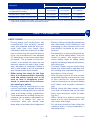
Important
This symbol identifies specially important technical information that must
not be ignored.
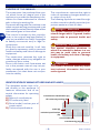
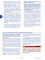
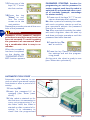
IDENTIFICATION OF MANUFACTURER AND APPLIANCE
The dataplate shown here is fitted directly to the appliance. It
features references and all essential information for operating
safety.
A) Name of manufacturer
B) CE conformity label.
C) Serial model/number year of
construction.
D) Technical specifications
manufacturer identification (A)
CE conformity marking (B)
C141501700.fm
GB
The manufacturer reserves the right to
make all necessary changes without prior notice of any kind.
The following symbols are used throughout this manual to identify particularly important sections of text or data.
The constructor has produced this manual, which forms an integral part of the
appliance, to provide the necessary information for those authorised to interact
with it during its working life.
Personnel working with the machine must
adopt correct working practices and must
also carefully read and strictly follow all the
instructions given in this manual.
This manual is written by the manufacturer in the original language (Italian). It
may be translated into other languages
to satisfy commercial and/or legal requirements.
Study this manual carefully. It will help
you avoid unnecessary risks to personal
health and safety and risks of damage to
equipment.
The constructor reserves the right to
make changes without any obligation to
provide any prior notice.
Some information and illustrations set
out in the present manual may not perfectly correspond with the one in your
possession, but that does not compromise its validity.
model (C)
technical specifications
(D)
serial number (C)
manufacturing year (C)
IDM - 41501700100.tif
-4-
User's manual
REQUESTING TECHNICAL ASSISTANCE
For every technical service request regarding the machine, please indicate the
data found on the identification plate, the
approximate hours of use and the type of
fault detected.
TECHNICAL INFORMATION
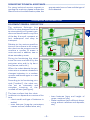
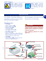
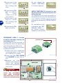
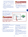
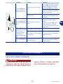
EQUIPMENT GENERAL DESCRIPTION
The appliance Ambrogio Line
200 is a robot designed and built
to automatically trim grass in gardens and house lawns in any time
of the day. It is small, compact, silent, waterproof and easy to
transport.
GB
Relative to the various specifications of the sufrace to be mown,
the robot can be programmed to
machine a number of areas: a
main one and, in addition, two or
three secondary areas.
robot
During its functioning the robot
trims the area marked off by the
perimeter wire and/or by barriers (fences, walls, etc.)
When the robot detects the perimter wire or meets an obstacle it
changes trajectory in a random
manner and starts again in a new
direction.
robot
C141501700.fm
According to its functioning principle ("random"), the robot carries out an automatic and
complete trimming of the
marked off lawn (see figure).
IDM - 41501700200.tif
The lawn surface that the robot
is able to trim depends on a series of factors.
– robot model and type of batteries installed
– area features (irregular perimeters,
uneven surface, divided area, etc.)
– lawn features (type and height of
grass, moisture, etc.)
– blade conditions (with efficient sharpening, without residues and deposits,
etc)
-5-
User's manual
All models are equipped with a sensor
which, when it rains, stops the blade and
makes the robot return to its recharging
station.
On request, models can be equipped
with an amplified transmitter, electromagnetic interferences filter, electronic
alarm and power supply protection box.
For more details, consult the table showing technical data
Important
Each robot is provided with a recognition
password in order to impede its use
should it be stolen.
The power supply unit (L) varies according to the type of batteries installed (lead or lithium batteries).
When the purchased, the password inserted by the manufacturer comprises
four numbers (0000).
– Impacts sensor (M): detects robot
impact against an obstacle and enables a change of trajectory in a random manner.
– Remote control (N): it is used to
check the robot functions in a remote
position.
– Rain sensor (P): detects rain and enables the return of the robot to its
charging station (P).
– Sensor (Q): detects the perimeter
wire and enables a change of robot
trajectory in a random manner.
To customise the password see "Programming mode" (§ "Enter password").
-6-
User's manual
C141501700.fm
GB
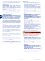
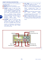
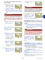
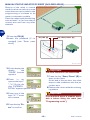
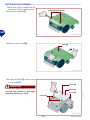
Main parts
– Accumulator batteries (A): they energize the motors of the blade and of
the wheel control system.
The robot is supplied with lead batteries or with one or two lithium batteries, which assure a longer working
session.
– Recharging station (B): used to
charge or keep the batteries charged
(A).
– Electronic card (C): it checks the automatic functions of the robot.
– Control keyboard (D): it is used to set
and visualise the functioning modes of
the robot.
– Cutting blade (E): it trims the lawn.
– Electric motor (F): it starts the cutting blade (E).
– Electric motor (G): one actions the
right wheel transmission group while
the other actions the left wheel.
– Transmitter (H): it transmits the signal to the perimeter wire.
– Power supply unit (L): it energizes, at
low tension, the battery power.
The robot Ambrogio Line 200 is produced in the BASIC, DELUXE and EVOLUTION versions.
BASIC version: basic model which can
mow surfaces up to 1500 m2. On request, it can be equipped with two lead
batteries or a lithium battery.
DELUXE version: model able to mow
surfaces up to 2600 m2. On request, it
can be equipped with two lithium batteries, which make it possible to mow surfaces up to 3000 m2.
EVOLUTION version: model able to mow
surfaces up to 3000 m2. It is equipped
with two lithium batteries, telecommand
and sensor to detect the "mown lawn".
Rain sensor (P)
signal transmitter (H)
control keyboard (D)
Reload station (B)
power supply unit (L)
electric motor (F)
GB
accumulator
batteries (A)
shock sensor
(M)
remote control (N)
Perimeter wire
sensor (Q)
cutting blade (E)
electronic card (C)
electric motor (G)
IDM - 41501700300.tif
SPECIFICATIONS
Model
Description
C141501700.fm
Cutting blade 4
BASIC
DELUXE
EVOLUTION
(mm)
220
290
290
Cutting speed
(m/min)
25
25
25
Cutting height
(mm)
20-60
20-60
20-60
Maximum gradient of the surface
to trim
Electric motors
Size (basexheightxdepth)
27°
(V)
(mm)
cc (24V)
cc (24V)
cc (24V)
610x410x265 610x410x265 610x410x265
Robot weight (without batteries)
(kg)
9,2
9,2
9,2
Ambient functioning temperature
Max
40°
40°
40°
-7-
User's manual
Model
Description
BASIC
DELUXE
EVOLUTION
Battery accumulator recharge type
battery accumulators (lead)
(V/A)
27,6V - 4A
battery accumulators (lithium)
(V/A)
29,3V - 4A
29,3V - 4A
29,3V - 4A
Maximum surface that can be trimmed
m2
1500
-
-
Robot with one lithium battery
(25.2V-6A)
m2
1500
2600
-
Robot with two lithium batteries
(25.2V-6A)
m2
-
3000
3000
Electric specifications
Power supply unit (for lead
battery)
Class 1 (Vin 115-230 Vac 50Hz) Fuse 5x20 4A
F (inside) 27,6 Vac Fuse 5x20 10A F
(replaceable) Selector 115-230 Vac
Power supply unit (for lithium
battery)
Class 1 (Vin 115-230 Vac 50Hz) Fuse 5x20 4A
F (inside) 29,3 Vac Fuse 5x20 10A F
(replaceable) Selector 115-230 Vac
Section perimeter wire (to lay
underground)
Perimeter wire maximum length
(approximate, calculated
according to a regular perimeter)
(mm)
ø1,5
ø1,5
ø1,5
(m)
600
600
600
Fittings
Sinusoidal perimeter signal
(patented)
standard
standard
standard
Rain sensor
standard
standard
standard
Intelligent spiral
not available
standard
standard
Blade modulation
not available
standard
standard
Trimmed lawn sensor Auto-programming (patented)
not available
not available
standard
Remote control
on request
on request
standard
Alarm
on request
on request
standard
Kit for working with gradients
higher than 27° (1)
on request
on request
standard
100
150
150
Perimeter wire
(m)
Fixing nails
(n°)
100
200
200
Upgraded transmitter
on request
on request
on request
Electromagnetic interference
filter
on request
on request
on request
Power supply safety box
on request
on request
on request
-8-
User's manual
C141501700.fm
GB
Robot with two lead batteries
(12V-12A)
Model
Description
BASIC
DELUXE
EVOLUTION
Battey charger kit (winter period
or extended inactivity)
on request
on request
on request
Wheels with "nailed" tread
on request
on request
on request
Wheels with "claws" profile tread
on request
on request
on request
(1) If the ground conditions are suitable (solid, without excessive folds, etc.), the kit allows the robot to work (within
certain limits) beyond the maximum admissible gradients.
GB
SAFETY INFORMATION
C141501700.fm
SAFETY RULES
– Perform lifting and handling observing
the information found directly on the
packaging, on the machine and in the
instructions furnished by the manufacturer.
– Pay attention to the symbols that appear on all the safety labels. They are
coded by colour and shape to enhance safety. Keep all safety labels
legible and always respect the instructions they give.
– The lawn mower may be used only by
those who know how to operate it after reading and understanding the instructions in this manual.
– Only use the machine for the purposes specified by the manufacturer. Use
of the machine for other purposes
may be hazardous to personal safety
and health and provoke economic
loss.
– Before using the lawn mower make
sure that no objects are on the lawn
(toys, tree branches, items of clothing, etc.).
– When using the machine, make sure
there are no risks especially for children, pets and things.
– Do not place hands or feet under the
machine when running especially in
the wheel area.
– During design and construction, the
manufacturer has carefully considered the possible hazards and personal risks that may result from
interaction with the machine. In addition to observing the specific laws in
force, the manufacturer has adopted
all "exemplary construction technique
principles". The purpose of this information is to advise the users to use
extreme caution to avoid risks. However, discretion is invaluable. Safety is
also in the hands of all the operators
who interact with the machine.
– When using the robot for the first
time, it is recommended to carefully
read the whole manual and to be
sure to have it completely understood, in particular all the information relating to safety.
– Carefully read all instructions in this
manual and those applied directly to
the machine, taking particular care to
read and follow safety precautions.
Time dedicated to reading these precautions can prevent regrettable accidents. It is always too late to
remember what you should have
done after an accident has happened.
-9-
User's manual
SAFETY FOR MAN AND THE ENVIRONMENT DURING DISPOSAL
sanctions regulated by the laws in force
in the territory where the infraction has
been verified.
As implementation of the European directives (2002/95/CE, 2002/96/CE,
2003/108/CE) in the Italian territory,
for example, a law decree (n. 151 dated
July 25 2005) has been enacted, thus
providing for an administrative fine of
€ 2000÷5000.
Do not dispose of pollutant materials in
the environment. Dispose of all such
materials in compliance with applicable legislation.
With reference to the WEEE directive
(Waste of Electrical and Electronic
Equipment), during dismantling, the user
must separate the electrical and the
electronic components and dispose
them in the appropriate authorized collection centres or give them back as they
are to the seller, when a new purchase is
made.
All the components, which must be separated and disposed of in a specific manner, are marked with a special mark.
The unauthorized disposal of Waste of
Electrical and Electronic Equipment
(WEEE) is subject to fine according to
Danger - Attention
The Waste of Electrical and Electronic
Equipment may contain dangerous
substances with potentially harmful effects on the environment and on people. It is recommended to correctly
dispose them.
- 10 -
User's manual
C141501700.fm
GB
– Always remove the blade before replacing the batteries.
– In order not to irreversibly damage
electric and electronic parts, do not
wash the robot with water jets at a
high pressure and do not plunge it
partially or thoroughly in water, as it
is not watertight.
– The operators performing repair interventions during the working life of
the robot must have technical expertise, special abilities and experience,
acquired and acknowledged in this
specific sector. The lack of these requirements may cause damage to the
safety and health of people.
– All operations, which must be carried
out in the recharge base (optional),
must be performed with the power
supply plug disconnected.
– Replace deteriorated parts with originals to ensure functionality and the
foreseen safety level.
– Never tamper with, avoid, remove or
bypass installed safety devices. Such
actions could lead to serious risk to
personal health and safety.
– Keep the lawn mower in perfect operating conditions by performing the
maintenance procedures outlined by
the manufacturer. Good maintenance
guarantees better performance and
longer service life.
– Before maintenance and setting procedures are performed – also by the
user, if possessing the necessary
technical skills – disconnect the power supply. The user must in any case
operate in full safety conditions, especially when working on the lower part
of the lawn mower, following the procedures as illustrated by the manufacturer.
– Use personal protections as recommended by the manufacturer, especially the protective gloves when
handling blades and cutting discs.
SAFETY SIGNALS
Safety signal: indicates
that the user should carefully read the manual before operating the lawn
mower.
Danger signal: indicates
that the user should not approach to the blades while
the lawn mower is operating.
INSTALLATION
PACKAGING AND UNPACKING
GB
The machine is delivered suitably packaged. When unpacking, remove carefully
and check component integrity.
All the necessary information for handling is found on the packaging.
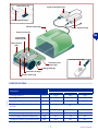
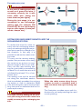
Packaging content
– Robot (A);
– Power supply unit (B)
– Power supply cable (C)
– Reload station (D)
– Transmitter (E)
– Perimeter wire hank (F)
– Nails (G) for wire fixing
– User manual (H)
– Lithium or lead accumulator batteries
(L): the quantity of batteries can vary
relative to the purchase order.
– Blade (M)
– Telecommand (N) (only for some versions, see "Specifications").
Important
The list includes only the components
supplied with the equipment. Check the
quantity and the integrity of any optional parts requested.
Keep packaging material for subsequent use.
wire fixing nails (G)
user manual (H)
C141501700.fm
perimeter wire (F)
robot (A)
cutting blade
(M)
transmitter (E)
power supply
unit (B)
power cable (C)
remote control (N)
accumulator batteries
(L)
- 11 -
Reload station (D)
IDM - 41501700400.tif
User's manual
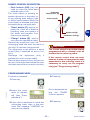
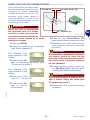
EQUIPMENT INSTALLATION PLANNING
the charging station, power supply-transmitter group and to lay out the perimeter wire.
Robot installation does not involve interventions that are difficult to carry out,
but requires a minimum of preliminary
planning to define the best area to install
power supply-transmitter
unit
power supplytransmitter unit
perimeter wire
Reload station
wire laying direction
perimeter
wire
IDM - 41501700500.tif
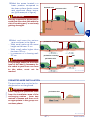
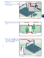
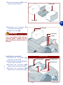
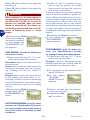
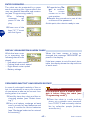
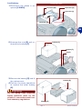
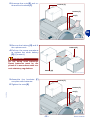
– The recharging station must be
positioned on a flat and stable
surface and able to guarantee
good drainage to avoid flooding.
power supply-transmitter unit
IDM - 41501700600.tif
– The section of input wire must
be rectilinear and aligned perpendicularly to the recharging
station for at least 2 m and the
output section must be located
at least 30 cm from the recharging station; this makes it
possible for the robot to enter
correctly.
power supply-transmitter unit
C141501700.fm
GB
Power
supplier-transmitter
group and recharging station installation area
– Power
supplier-transmitter
group and recharging station
must be installed inside the
main work area and near to
each other.
IDM - 41500902400.tif
- 12 -
User's manual
Warning - Caution
Important
To carry out electric connection, it is
necessary to arrange a power supply
socket near the installation area. Make
sure that the connection to the power
supply complies to the laws in force on
the subject.
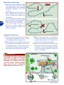
To permit the robot to re-enter the recharging station, it is necessary to install the same within the work area
having larger dimensions, hereafter referred to as the "Main Area".
– Make sure that any irrigators ,
present in the installation area do not
direct a jet of water into the recharging station.
– The transmitter - power supplier
group must be in a ventilated position,
protected from the atmospheric
agents and from direct sunlight.
– The transmitter - power supplier
group must not be in direct contact
with the ground and damp environments.
Important
Is it advisable to install the unit in a
closet for electric components (for outdoors or indoors), well ventilated to
keep a correct air recirculation and
provided with a key closure.
Warning - Caution
Assure that the access to the power
supply-transmitter unit is allowed only
to authorized people.
C141501700.fm
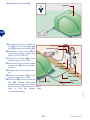
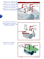
Perimeter wire path definition
– Check the whole surface of the
lawn and assess whether it is
necessary to divide it in more
separated working areas.
– When positioning the perimter
wire, respect the rotation direction around the bays (anticlockwise).
– Define the perimeter of the
main area, any secondary areas, and carry out the operations in the sequence indicated.
1-Preparation and delimitation
of work areas (main and secondary) (see page 14)
2-Perimeter wire installation
(see page 17)
3-Installation of recharging station and transmitter-power
supplier group (see page 20)
track for perimeter wire
laying
IDM - 41500902500.tif
- 13 -
User's manual
GB
PREPARATION AND DELIMITATION OF WORK AREAS
(MAIN AND SECONDARY)
IDM - 41501600700.tif
If the proper kit is installed and the conditions of the ground are suitable (solid,
without excessive folds, etc.), the robot
can work (within certain limits) beyond
the maximum admissible gradients.
see figure
Important
The areas, showing higher gradients
than those admitted cannot be
trimmed with the robot.
Marking of working area
3-Check the whole surface of the
lawn and assess whether it is
necessary to divide it in more
separated working areas.
Before starting installation operations of the perimeter wire,
to make them easy to perform,
it is recommended to properly
signal the whole path evenly
with straight lines and to trace
any curved line.
The figure represents an example of lawn with the trace
for the underground laying of
the perimeter wire.
track for perimeter wire
laying
C141501700.fm
GB
Arrangement of lawn to trim
1-Check that the lawn to trim is
even, and without pits, stones
or other obstacles. If so, perform the necessary clearance
operations.
If some obstacles cannot be
removed, it is necessary to
properly mark the areas involved.
2-Check that all the areas of the
lawn do not exceed the admissible gradients (see "Specifications"). During the work phase
on slopes, when the robot detects the wire the wheels may
slide and make it exit from the
perimeter area. To avoid this
problem, it is possible to install the
"Slopes kit" and the "Clawed" wheels.
IDM - 41501700800.tif
- 14 -
User's manual
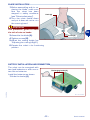
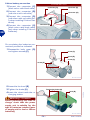
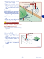
Important
To ensure the robot can operate,
it is necessary for the distance
separating the delimitation of
two elements to be greater than
70 cm. This distance is required
to permit robot passage.
When the connection between
one surface and another of the
lawn is represented by a passage (corridor) with a width of
less than 70 cm and not greater
than 2 m, it is necessary to delimit the same with the perimeter wire in a number of work
areas that are connected to
each other.
passage aisle
house
MAIN AREA
SECONDARY
AREA
GB
MAIN AREA
passage aisle (<
70cm)
house
Closed area
C141501700.fm
IDM - 41501700900.tif
- 15 -
User's manual
4-Mark and trace the perimeters of the inside and marginal
elements of the working area
that obstruct the correct functioning of the robot.
manhole
Important
bed
protruding roots
Mark and trace the perimeters
of all the elements in iron or in
other metals (manholes, electric
connections, etc.) to avoid interferences to the signal of the perimeter wire.
hedge
wall
shower dish
pool
IDM - 41501711400.tif
41501601100.tif
Do not mark those obstacles
(trees, poles, etc.) that do not
hamper the normal functioning
of the robot.
tree
pole
C141501700.fm
GB
The figure represents an example of inside an marginal elements of the working area and
the distances that must be respected for the tracing of the underground
laying
of
the
perimeter wire.
IDM - 41501701000.tif
- 16 -
User's manual
5-Mark the areas, located in a
lower position compared to
the lawn surface (pools, areas
with significant drops, stairs,
etc.) (see example in figure).
pool
elevated area
perimeter wire
Important
Strictly respect the distances to
avoid that the robot falls with the
risk of breaking and/or seriously
getting damaged.
IDM - 41501701100.tif
6-Mark and trace the perimeters as shown in the figure.
– With small paths at the same
height as the lawn: 5 cm
– With small paths higher than
the lawn: 35 cm
– In presence of a fencing wall:
35 cm
Important
pedestrian crossing
pedestrian crossing
perimeter wire
wall
perimeter wire
The passage paths (at the same
level of the lawn), necessary for
the robot to pass from one area
to the other, must not be
marked.
IDM - 41501701200.tif
PERIMETER WIRE INSTALLATION
The perimeter wire may be laid underground or on the ground.
C141501700.fm
Important
Start laying the perimeter wire
from the installation area of the
recharging station , leave two
metres in excess and then cut it
as appropriate in the group connections phase.
perimeter wire
IDM - 41501601600.tif
- 17 -
User's manual
GB
wire fixing nails
perimeter wire
wire fixing nails
perimeter wire
IDM - 41501600900.tif
Underground laid wire
1-Dig up the ground evenly and symmetrically compared to the traced
line highlighted on the ground.
2-Place the wire clockwise along the
whole path at the depth of some centimetres (about 2÷3 cm) so not to
reduce the quality and the intensity of
the signal captured by the robot.
Important
3-When laying the wire, if necessary,
block it in some points with the appropriate nails to keep it in position during the ground covering stage.
4-Cover up the whole wire with the soil
and make sure that it does not twist,
but that it remains straight and that,
in the curving stretches, it takes on
an even bending.
MAIN AREA
passage aisle (<
70cm)
In the path stretches, where it is
necessary to pass two parallel
wires (for example: connection
between the outside perimeter
and the inside marked areas),
they must be at a distance,
which must not exceed 1 cm.
C141501700.fm
GB
Wire laid on the ground
1-Place the wire clockwise along
the whole path and fix it with
the appropriate nails supplied
(distance between the nails
1÷2 m).
– When positioning the perimter
wire, respect the rotation direction around the bays (anticlockwise).
– In the straight stretches, fix the
wire so that it is not excessively
tight, wavy and/or twisted.
– In the not straight stretches, fix
the wire so that it does not
twist, but so that it takes on a
regular bending.
Closed
area
IDM - 41501701300.tif
- 18 -
User's manual
Perimeter wire joint
Important
In the case of underground wire
as well as of ground laid wire, if
necessary, properly join it with
some other wire, having the
same features (see figure).
During the joint stage, it is recommended to use self-amalgamating tape (for example: 3M
Scotch 23). Do not use isolating
tape or other types of joints (terminals, clamps, etc.).
IDM - 41501602000.tif
C141501700.fm
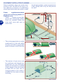
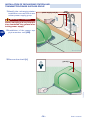
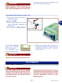
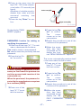
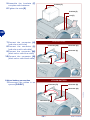
SETTING FOR RAPID ROBOT RE-ENTRY INTO THE
RECHARGING STATION
To reduce the times for robot reentry into the recharging station,
carry out settings along the perimeter wire to permit a change of robot direction. In this way, it is
possible to reduce the robot re-entry route.
To carry out the re-entry setting,
position the perimeter wire along
the route< so as to form an equilateral triangle of 40 cm per side.
Carry out the rapid re-entry setting at a point that is preceded by
at least 2 m of rectilinear wire and
is followed by at least 1.5 m of rectilinear wire.
The setting must not be carried
out along the rectilinear section
that immediately precedes the recharging station or near to obstacles. Make
sure that along the rapid re-entry trajectory, there are no obstacles that can impede rapid re-entry.
IDM - 41501701400.tif
When the robot moves along the perimeter to reach a secondary area it
does not detect the rapid re-entry setting.
The illustration provides some useful indications for correctly installing the rapid
re-entry setting.
Important
The rapid re-entry setting at an incorrect point may prevent the robot from
rapidly re-entering the recharging station.
- 19 -
User's manual
GB
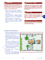
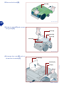
INSTALLATION OF RECHARGING STATION AND
TRANSMITTER-POWER SUPPLIER GROUP
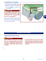
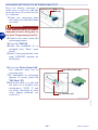
1-Identify the recharging station
installation area and the transmitter-power supply group.
power supply unit (A)
Warning - Caution
Before carrying out any intervention deactivate the general electricity power supply.
2-Installation of the power supply-transmitter unit (A-B).
transmitter (B)
IDM - 41501701700.tif
3-Remove the shield (L).
guard (L)
IDM - 41501701500.tif
- 20 -
User's manual
C141501700.fm
GB
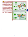
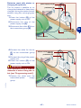
4-Position the base in the predefined area.
5-Insert the perimeter wire (M)
under the base.
Black terminal
Red terminal
GB
perimeter wire (M)
IDM - 41501701600.tif
6-Connect the two ends of the
wire to the terminals of the
base.
Red terminal
Black terminal
Black terminal
Red terminal
IDM - 41501711600.tif
C141501700.fm
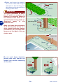
7-Fasten the base (N) to the
ground with nails (P). If necessary, fasten the base with expansion inserts (Q).
Reload station (N)
nails (P)
Expansion inserts (Q)
IDM - 41501701800.tif
- 21 -
User's manual
8-Reposition the shield (L).
guard (L)
GB
IDM - 41501701500.tif
led (H)
transmitter (B)
power cable (E)
perimeter
wire
IDM - 41501701700.tif
C141501700.fm
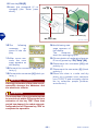
9-Connect the power supply cacursor (C)
ble (E) of the recharging station (F) to the transmitter (B).
pushbutton (D)
10-Operate on the cursor (C) to
select the power supply voltage (110 V or 220 V).
11-Press the button (D) of the
power supply unit on OFF.
led (G)
12-Connect the plug of the power
supply unit (A) to the power
power supply
socket.
unit (A)
13-Restart the main electric supply.
14-Press the button (D) of the
power supply unit on ON.
15-If the led (G) turns on and the
Reload station
led (H) flashes alternately
green and orange, the connection is correct. Otherwise, it is necessary to find the defect (see
"Troubleshooting").
- 22 -
User's manual
BLADE INSTALLATION
1-Before assembling and/or replacing the blade, make sure
that the robot has been
stopped in safety conditions
(see "Robot safety stop").
2-Turn the robot upside down
and put it down so not to ruin
the covering hood.
blade (A)
Important
Use protection gloves to avoid
the risk of cuts on hands.
GB
3-Assemble the blade (A).
4-Tighten screws (B).
5-Adjust the cutting height (ee
"Adjusting the cutting height").
6-Capsize the robot in its functioning
position.
screws (B)
IDM - 41501702900.tif
BATTERY INSTALLATION AND CONNECTION
The robot can be energized with
two lead batteries or with one or
two lithium batteries.
Install the batteries as shown.
1-Undo the knobs (A).
C141501700.fm
Recharging knobs (A)
IDM - 41501701900.tif
- 23 -
User's manual
2-Remove the hood (B).
hood (B)
IDM - 41501702000.tif
GB
3-Undo the bolts (C) and remove
the guard (D).
screw (C)
guard (D)
screw (C)
screw (C)
IDM - 41501702100.tif
4-Unscrew the nuts (E) and unthread the brackets (F).
bracket (F)
nut (E)
IDM - 41501702200.tif
- 24 -
User's manual
C141501700.fm
bracket (F)
5-Insert the batteries (G) in the
appropriate positions.
battery (G)
battery (G)
IDM - 41501702300.tif
6-Assemble the brackets (F)
complete with batteries.
7-Tighten the nuts (E).
bracket (F)
bracket (F)
Important
The connection must be carried
out in accordance with the procedures given, relative to the
type of battery installed (lead or
lithium).
nut (E)
C141501700.fm
IDM - 41501702400.tif
Lead battery connection
1-Connect the connector (H)
(red colour with blue)
2-Connect the connector (L) (red
colour with red cable)
3-Connect the connector (M)
(black colour with blue cable)
4-Connect the connector (N)
(black colour with black cable)
LEAD BATTERY
connector (M)
connector (H)
connector (L)
connector (N)
IDM - 41501702500.tif
- 25 -
User's manual
GB
LITHIUM BATTERY
connector (R)
connector (P)
connector (Q)
connector (S)
IDM - 41501702600.tif
On completing the batteries connections proceed as indicated.
1-Reassemble body cover (D)
and tighten screws (C).
screw (C)
guard (D)
screw (C)
screw (C)
IDM - 41501702700.tif
2-Assemble the hood (B).
3-Tighten the knobs (A).
4-Insert the robot inside the recharging station.
Recharging knobs (A)
hood (B)
Warning - Caution
Before performing the first recharge, check that the power
supply unit is suitable for the
type of batteries installed (power supply unit for lead or lithium
batteries).
IDM - 41501702800.tif
- 26 -
User's manual
C141501700.fm
GB
Lithium battery connection
1-Connect the connector (P)
(black colour with black cable)
2-Connect the connector (Q)
(red colour with red cable)
3-Connect the connector (R)
(red colour with red cable) (only when installing 2 lithium batteries).
4-Connect the connector (S)
(black colour with black cable)
(only when installing 2 lithium
batteries).
At this point, the robot is ready to use
(see "Use and functioning").
Important
Before using the robot, perform a complete recharge of the new batteries
(see "Recharge batteries on first use").
RECHARGE BATTERIES ON FIRST USE
1-Insert the robot inside the recharging station.
2-Press key ON.
3-After a few seconds the message "LOADING" appears on
the display.
4-Press the key "Start/Pause".
Key
“ON”
GB
Key
“Start/Pause”
IDM - 41501703000.tif
On the display the display the "PAUSE"
function appears.
The batteries start
the recharging cycle.
5-When recharging has finished it is
possible to programme the robot for
operational activity (see "Programming mode").
Important
At the first recharge, the batteries
must be connected at least 24 hours.
C141501700.fm
ADJUSTMENTS
ADJUSTMENT REMINDERS
Important
Any extraordinary adjustments, not explicitly indicated in the manual, must be
carried out only by the staff of the Authorized Assistance Centres of the
Manufacturer.
The user must carry out the adjustments according to the procedures described in the manual. Do not perform
any adjustments not explicitly indicated in the manual.
- 27 -
User's manual
ADJUSTING THE CUTTING HEIGHT
Before setting the cutting height of the
blade, make sure that the robot has
stopped in safety conditions (see "Robot
safety stop").
1-Disenable the antitheft alarm
to avoid activation (see "Programming mode").
Important
blade (A)
Use protection gloves to avoid
the risk of cuts on hands.
2-Turn the robot upside down
and put it down so not to ruin
the covering hood.
3-Remove the screws (B) to remove the blade (A).
screws (B)
IDM - 41501702900.tif
4-Unscrew the bolt (C).
5-Lift or lower the cutting group
(D) to define the height of the
mowing you want. The value
can be measured using a
graduated scale.
6-When the adjustment has
been carried out, tighten the
screw (C) and reassemble the
blade.
The greater the excursion of
the cutting group (D), the lower the height of the lawn after
mowing.
cutting group (D)
screw (C)
IDM - 41501610300.tif
Important
C141501700.fm
GB
Gradually reduce the cutting
height. it is advised to reduce the
height by less than 1 cm every 1÷2
days until reaching the ideal height.
7-Capsize the robot in its functioning
position.
- 28 -
User's manual
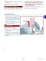
RAIN SENSOR ADJUSTMENT
1-Stop the robot in safety conditions (see "Robot safety stop").
2-Adjust the distance between
the pins (A-B) via rotation of
the pin (A).
pin (B)
eccentric pin
(A)
Important
The sensitivity of the sensor increases with a decrease in the
distance between the pins. We
recommend not bringing the
pins. too close together
GB
When the sensor detects rain
conditions, the robot carries out
its functions as programmed (see
"Programming mode").
IDM - 41501710400.tif
USE AND FUNCTIONING
RECOMMENDATIONS FOR USE
Important
Use the equipment only for the tasks
authorised by the manufacturer and do
not tamper with any device to achieve
a different performance from the operating one.
C141501700.fm
When using the robot for the first
time, it is recommended to carefully
read the whole manual and to be sure
to have it completely understood, in
particular all the information relating
to safety.
- 29 -
User's manual
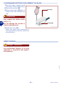
ROBOT CONTROLS DESCRIPTION
Key “ON” (B)
Key “Start/Pause” (C)
display (A)
Key “-” (H)
Key “Charge” (D)
Key “Enter” (G)
Key “Off/Stop” (E)
Key “+” (F)
IDM - 41501703500.tif
- 30 -
User's manual
C141501700.fm
GB
E) OFF/STOP: press to stop the lawn
mower; the display turns off.
F) Key "+": when working, press to
restart the previously stopped blade.
When programming press to
increase the items indicated by the
menu.
G) ENTER: when working, press to start
the
spiral
function.
When
programming press to confirm and
save the selection performed.
H) Key "-": when working, press to stop
the blade. When programming press
to decrease items indicated by the
menu.
The figure shows the control position on
machine board.
A) Display: shows all functions.
B) ON: press to turn on the lawn mower.
C) PAUSE: press to stop the lawn
mower, the display is in “stand-by”; it
is now possible to program the lawn
mower. When pressed again, the
lawn mower resumes working. If the
key is pressed during battery
recharging, the lawn mower does not
resume working until the key is
pressed
again
and
'Pause'
disappears from the display.
D) CHARGE: press to bring the lawn
mower back to the base and
recharge the battery in advance. If
the key is pressed while the lawn
mower is recharging, recharging is
interrupted and the lawn mower
resumes working.
REMOTE CONTROL DESCRIPTION
– Push buttons (A-B): they are
used to make the robot bend
towards right or left.
pushbutton
The robot keeps on bending to“Start/Pause” (C)
wards a direction or the other until the relating push button (right
Left arrow (A)
or left) is kept pressed. When the
push button is released, the robot
proceeds along a straight path.
– "Start" button (C): used to activate the robot at a distance
(handling, stop and restart of
Right arrow (B)
the blade and transfer from
pushbutton “Charge”
one area to another).
– "Charge" button (D): used to
carry out the operations listed.
Remove the equipment from the
recharging base and start the work cyImportant
cle only if it has been programmed.
The equipment must perform a spiral
The remote control is provided already
motion (only if switched on and in moprogrammed with a univocal code astion).
sociated to the referring robot.
Recharge the equipment (only if
If the remote control does not work,
switched on and in pause mode).
because it does not recognize the code
Remove the equipment from the perimeassociated to the referring robot, it is
ter wire if the equipment follows the wire
necessary to carry out its programand does not perform its work correctly.
ming (see "Programming mode").
IDM - 41501703600.tif
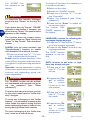
PROGRAMMING MODE
4-Press key.
C141501700.fm
Proceed as indicated.
1-Press key.
On the display the display the "PAUSE"
function appears.
2-Insert the password (if requested) (see "Enter
password").
5-Press key.
3-If the robot is switched on inside the
recharging base, after a few seconds, the message "LOADING" appears on the display.
- 31 -
User's manual
GB
To switch off the alarm it is necesary to
proceed as indicated.
2-Switch on the robot.
3-Access the "ALARM" function.
4-Press one of the keys "+", "-" to display "Disenable".
5-Insert the password (see "Enter
password").
6-Press the key "Enter" to switch off
the acoustic alarm.
The function "LANGUAGE" appears on
the display.
The "ALARM" function appears on the
display.
Important
To memorise the function displayed,
press the key "Pausa" or the key "Enter".
The function does not remain memorised if you press key "Stop" before key
"Enter" or key "Pausa". The robot deactivates.
LANGUAGE: function for selecting the
messages display language.
1-Press the "+" Key and the "-" Key to
scroll the available languages.
2-Press the key "Enter" to confirm the
language selected.
The "DATE" function
appears on the display.
ALARM: (only for some versions, see
"Specifications") function to enable
and disenable the antitheft function.
1-Press one of the keys "+", "-" to activate or deactivate the functions.
Enable: used to activate the alarm. If the
robot is lifted using the handle, the alarm
is triggered. A triple sound signals activation.
Disenable: used to deactivate or switch
off the alarm where there is activation. A
continual and descending sound indicates deactivation.
DATE: function to set solar or legal
time, day, month and year.
1-Press one of the
keys "+", "-" to set
the day.
2-Press the key "Enter" to confirm.
The
cursor
moves on to the
next position.
Important
The "ALARM" function can be activated, deactivated and stopped only by using the password (see "Enter
password").
To ensure the alarm functions correctly, the robot must have its "buffer battery" charged.
3-Press one of the
keys "+", "-" to set
the month.
To carry out recharging of the "buffer
battery" , it is necessary to start up the
robot inside the station during the batteries recharging phase or leave it functioning during normal work activity.
C141501700.fm
GB
If you press the key "Pausa", "PAUSE"
appears on the display. If, however, you
press the key "Enter", the next function
appears on the display.
4-Press the key "Enter" to confirm.
The
cursor
moves on to the
next position.
The first recharging of the "buffer battery" must be at least 6 hours.
- 32 -
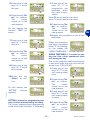
User's manual
1-Press one of the
keys "+", "-" to
programme the
weekdays when
the robot is operational.
Value 0: day of rest for the robot.
Value 1: day of rest for the robot.
5-Press one of the
keys "+", "-" to set
the year.
6-Press the key "Enter" to confirm.
The
cursor
moves on to the
next position.
2-Press the key "Enter" to confirm.
The
cursor
moves on to the
next position.
3-Repeat the procedure to set all the
weekdays.
On the display the
function "TIME" appears.
7-Press one of the
keys "+", "-" to set
the time.
When the procedure
has been completed
(letter "S" for Sunday),
on the display the
"WORK TIMETABLE 1" function appears.
8-Press the key "Enter" to confirm.
The
cursor
moves on to the
next position.
WORK TIMETABLE 1: function for setting the first robot operational time
slot during the day.
The cursor positions itself automatically
in the area under the first time slot (example from 7:30 to 9:30).
1-Press one of the
keys "+", "-" to set
the mowing start
time.
9-Press one of the
keys "+", "-" to set
the minutes.
C141501700.fm
10-Press the key
"Enter" to confirm.
2-Press the key "Enter" to confirm.
The
cursor
moves on to the
next position.
3-Press one of the
keys "+", "-" to set
the mowing start
minutes.
On the display the
"SETTIM." function
appears.
SETTIM: function for programming the
days of robot activity during the week.
The cursor positions itself automatically
in the area under the letter "L" (Monday).
4-Press the key "Enter" to confirm.
The
cursor
moves on to the
next position.
- 33 -
User's manual
GB
On the display the
"WORK TIMETABLE
2" function appears.
6-Press the key "Enter" to confirm.
The
cursor
moves on to the
next position.
7-Press one of the
keys "+", "-" to set
the mowing end
minutes.
WORK TIMETABLE 2: function for setting the second robot activity time slot
during the day.
To programme the work timetable for
the second time slot of the day (example
from 19.00 to 22.00) repeat the same
procedure indicated for "WORK TIMETABLE 1".
On completion of the
procedure, the "SECONDARY AREA 1 No. Cycles" function
appears on the display.
8-Press the key "Enter" to confirm.
SECONDARY AREA 1: function
to define automatic mowing of a
secondary area 1.
Programme the time that the robot takes to reach the secondary
area along the perimeter wire.
Keep to the following instructions
to detect the time:
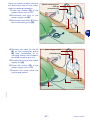
1-Position the robot outside the
recharging base in the direction of the wire in output.
2-Press the keys ON, PAUSA
and CHARGE to start the robot.
3-Measure the time
that the robot takes to
reach the half-way
point of the secondary
area route.
perimeter wire
IDM - 41501711300.tif
MAIN AREA
C141501700.fm
GB
5-Press one of the
keys "+", "-" to set
the mowing end
time.
Important
If along the route to
reach the secondary
area rapid re-entries
have been set, it is necessary to manually carry
SECONDARY
AREA 2
SECONDARY
AREA 1
IDM - 41501711500.tif
- 34 -
User's manual
9-Press the key to
confirm.
the robot immediately after rapid reentry setting.
4-Press the "+" Key
and the "-" Key to
enter the number
of work cycles to
perform in the
main area, the lawn mower starts
then to machine the first secondary
area.
Important
If secondary areas are provided (type 1
or 2), to complete the field of functions
relative to the number of cycles and time
it is necessary to insert the value 0.
On completion of the
procedure, on the
display the " SECONDARY AREA 2 No. Cycles" function appears.
Important
If secondary areas are provided (type 1
or 2), to complete the field of functions
relative to the number of cycles and
time it is necessary to insert the value
0.
SECONDARY AREA 2: function to define automatic mowing of a secondary
area 2.
1-To set the number of cycles and time
of the secondary area 2, repeat the
same procedure indicated for "SECONDARY AREA 1".
5-Press the key "Enter" to confirm.
On the display "SECONDARY AREA 1 Time" appears.
Important
If secondary areas are provided (type 1
or 2), to complete the field of functions
relative to the number of cycles and time
it is necessary to insert the value 0.
C141501700.fm
6-Press one of the
keys "+", "-" to insert the time (in
minutes) measured to reach the
secondary area.
On completion of the
procedure, on the
display the "PERIMETER" function appears.
7-Press the key "Enter" to confirm.
The
cursor
moves on to the
next position.
PERIMETER: function for setting the
robot with the impact or perimeter
wire recognition modality.
1-Press one of the keys "+", "-" to set
the type of delimitation installed
along the perimeter.
Select YES if the perimeter wire is installed.
Select NO if the perimeter wire is not installed.
Select ×2 in case of signal problems (perimeter wire installed).
8-Press one of the
keys "+", "-" to insert the time (in
seconds).
- 35 -
User's manual
GB
1-Press "+" and "-" to disable this option or set the percent of mowed
lawn grass to be used for auto-programming function start.
The auto-programming function reduces
machine work time based on grass conditions. When the lawn surface is cut in
a percent higher than the one set in the
"Autoprogramm." Menu item, the machine automatically set an idle interval
that delays the next exits from the charger base; the higher the percentage of
mowed lawn, the longer the machine idle
interval.
2-Press the key "Enter" to confirm.
On the display the
"TELECOMMAND"
function appears.
Select ×4 if the problem is not solved by
selecting ×2.
Select ×6 if the problem is not solved by
selecting ×4.
Important
2-Press the key "Enter" to confirm.
When the procedure
has been completed,
on the display the
"RAIN SENSOR" function appears.
TELECOMMAND: (only for some versions, see "Specifications") function
for reprogramming the telecommand.
1-Press one of the keys "+", "-" to select one of the functions.
Configure: used to reprogramme the
telecommand with the univocal code associated with the reference robot.
RAIN SENSOR: function for setting the
robot when it rains.
1-Press one of the keys "+", "-" to activate or deactivate the functions.
Disenabled: when it rains the robot continues to mow.
Pause: when it rains the robot returns to
the station and stays there (in "recharging" modality) until the key "Pause" is
pressed.
Restart: when it rains the robot returns
to the station and stays there in "recharging" modality. Once the recharging
cycle has finished the robot starts again
and only starts to mow if it is no longing
raining.
2-Press the key "Enter" to confirm.
On the display "AUTOPROGRAMMING" appears.
2-To reprogramme the telecommand
select "Configure".
3-On the display
"TELECOMMAND Configure"
appears.
4-Position yourself with the telecommand near the robot.
5-Press the key "Enter" to confirm.
AUTOPROGRAMMING: (only for some
versions, see "Specifications") function
for automatically reducing the mowing
time of the robot on the basis of lawn
conditions.
- 36 -
User's manual
C141501700.fm
GB
When switched on, the lawn mower is
automatically positioned in the Perimeter YES mode. The NO, ×2, ×4 and ×6
options are disabled when the lawn
mower is switched off. Use these options with great care and only in the absence of swimming pools or steep
slopes.
6-Press at the same time the
keys "DX", "SX" of the telecommnad within 10 seconds (see
figure).
Activation of a double sound indicates that robot and telecommand
matching
has
occurred.
7-Press the key "Enter" to confirm.
Left arrow (SX)
Right arrow (DX)
IDM - 41501709300.tif
4-Press the key "Enter" to confirm.
The
cursor
moves on to the
next position.
5-Repeat the procedure to set all the
numbers of the password.
On the display "PASSWORD" appears.
PASSWORD: function for setting or
modifying the password.
1-Press one of the keys "+", "-" to activate or deactivate the functions.
Yes: used to insert a new password.
No: used to leave the previously inserted
password.
2-Press the key "Enter" to confirm.
6-When the procedure has been
completed, on the
display the function "NEW PASSWORD" appears.
The cursor automatically positions itself
in the area under the first number.
7-Press one of the
keys "+", "-" to set
the first number.
Important
C141501700.fm
To set or modify the password it is necessary to first insert the previous one
and then proceed with insertion of the
customised one.
8-Press the key "Enter" to confirm.
The
cursor
moves on to the
next position.
9-Repeat the procedure to set all the
numbers of the password.
When the purchased, the password inserted by the manufacturer comprises
four numbers (0000).
3-Press one of the
keys "+", "-" to set
the first number.
10-When the procedure has been
completed, on the
display the "REPEAT PASSWORD" function appears.
- 37 -
User's manual
GB
PASSWORD STARTING: function for
programming or not the password insertion request each time the robot is
switched off and restarted after a period of inactivity (example, remessage
for winter season).
1-Press one of the keys "+", "-" to activate or deactivate the functions.
No: after a period of inactivity, the robot,
with each re-ignition, starts up and begins operations without the password
having to be inserted.
Yes: after a period of inactivity, the robot,
with each re-ignition, does not start up
and does not begin operations until the
password has been inserted.
11-Press one of the
keys "+", "-" to set
the first number.
12-Press the key
"Enter" to confirm. The cursor
moves on to the
next position.
Repeat the procedure to set all the numbers of the password.
Important
Repetition of the password insertion
procedure is used to be sure that it has
been set correctly. To avoid forgetting
the password, we recommend choosing a combination that is easy to remember.
2-Press the key "Enter" to confirm.
When the procedure
has been completed,
on the display the
"PASSWORD STARTING" function appears.
3-Press the key "Pausa" to memorise
the settings and exit the programming phase.
At this point, the robot is ready to use
(see "Automatic cycle start").
AUTOMATIC CYCLE START
Automatic cycle start-up is carried out when operational activity
first starts or after a period of inactivity.
1-Press key ON.
2-Insert the password (if requested) (see "Enter password").
3-If the robot is started up for
the first time, it is necessary to
carry out programming. If, on
the other hand, the robot is
started up after a period of inactivity, it is necessary to
check that the programmed
Key
“ON”
C141501700.fm
GB
IDM - 41501703000.tif
- 38 -
User's manual
functions correspond to the effective
status of the surfaces to be mown
(e.g. addition of a swimming pool,
plants etc.) (see "Programming
mode").
4-Adjust the cutting height (see "Adjusting the cutting height").
5-Adjust the sensitivity of the rain sensor (see "Rain sensor adjustment").
6-Position the robot inside the recharging station.
Important
If the antitheft alarm is enabled, disenable it before lifting the robot (see
"Programming mode").
7-After some seconds, on the display
the "LOADING" message appears.
8-The robot starts to mow the lawn in
accordance with the programmed
modalities.
GB
ROBOT SAFETY STOP
When using the robot, it may necessary to stop it in safety conditions to avoid the ranger to a
sudden start of the blade.
Press the key "Off/Stop" (A) to
stop the robot.
Important
The stop of the robot in safety
conditions is necessary in order
to carry out maintenance and repair interventions (for example:
battery replacement and/or recharge, blade replacement,
cleaning operations, etc.).
Key “Off/Stop” (A)
IDM - 41501710200.tif
C141501700.fm
ROBOT AUTOMATIC STOP
– Trimmed lawn
The sensor detects the mown lawn, the
robot automatically re-enters the recharging station and again starts to
function in accordance with programmed modalities (see "Programming mode").
– End of work period
When it has completed its work period,
the robot automatically re-enters the recharging station and again starts to
function in accordance with programmed modalities (see "Programming mode").
The robot stops automatically when the
listed conditions occur.
– Run-down batteries
The robot automatically re-enters the recharging station.
– Rain
When it rains the robot auotmatically enters the recharging station and functions in accordance with programmed
modalities (see "Programming mode").
- 39 -
User's manual
MANUAL STARTUP AND STOP OF ROBOT (IN CLOSED AREAS)
Start-up of the robot in manual
mode must be carried out to mow
areas that are not included in the
programming of surfaces to be
mown in automatic modality.
Place the robot inside the working
area at least 1 m far from the perimeter wire and from any other
obstacle.
IDM - 41501709500.tif
GB
1-Press key ON (A).
2-Insert the password (if requested) (see "Enter password").
Key “ON” (A)
Key “Start/Pause” (B)
IDM - 41501710200.tif
3-On the display the
display
the
"PAUSE" function
appears.
Important
The value inserted is not memorised.
4-Press
in
sequence the keys "", "+". On the display "EXTERIOR 60 Min" appears (default value).
5-Press one of the
keys "+", "-" to set
the minutes.
Important
If the antitheft alarm is enabled, disenable it before lifting the robot (see
"Programming mode").
6-Press the key "Enter" to confirm.
- 40 -
User's manual
C141501700.fm
7-Press the key "Start/Pause" (B) to
start up the robot.
At the end of the set time, the robot
stops in safe conditions near the perimeter wire.
8-Position the robot inside the recharging station.
ROBOT START WITHOUT PERIMETER WIRE
This mode can be carried out with
the remote control to perform the
trimming of areas completely
marked by fences or to trim, for
example, small areas, where it
was not possible to mark or for
practical demonstrations on the
functioning of the robot
Key “ON” (A)
Key “Start/Pause” (B)
Important
When the robot is used without
the perimeter wire, it is recommended to make sure that the
robot does not hit into obstacles,
corners or blunt objects so to avoid
damages or breaks.
Key “Off/Stop” (C)
GB
IDM - 41501710200.tif
6-Press the key "Start/Pause" (B)
twice consecutively to start the robot
7-Manoeuvre the robot with the telecommand (see "Remote control description").
1-Press key ON (A).
2-Insert the password (if requested)
(see "Enter password").
Important
The following message appears of the
display:
3-Press the key "Enter" until displaying "Perimeter" (see
"Programming mode").
It is advisable to operate the robot with
the remote control to carry out the
trimming inside a narrow area, well visible and to avoid, if possible, making it
hit into obstacles.
8-Having finished mowing, press the
key "Off/Stop" (C) to stop the robot
in safely (see "Robot safety stop").
The following message appears of the
display:
4-Press one of the
keys "+", "-" to set "NO".
Important
If the antitheft alarm is enabled, disenable it before lifting the robot (see
"Programming mode").
5-Press the key "Enter" to confirm
the selection.
C141501700.fm
9-Position the robot inside the recharging station.
- 41 -
User's manual
ENTER PASSWORD
3-Press the key "Enter" to confirm.
The
cursor
moves on to the
next position.
4-Repeat the procedure to set all the
numbers of the password.
At this point, the robot is ready to use.
The robot can be protected by a password comprising four figures which the
user can enable, disenable and customise (see "Programming mode").
1-The
following
message
appears of the display:
DISPLAY VISUALISATION IN WORK PHASE
When the lawn mower is being recharged, the message "RECHARGE" appears in the display.
While the lawn mower is operating, the
following data are displayed:
– Left wheel motor speed
– Cutting blade motor speed
– Right wheel motor speed
– Battery voltage.
If the lawn mower is out of its work timetable, the display shows the day and time
of work start.
PROLONGED INACTIVITY AND SERVICE RESTART
In case of prolonged inactivity of the robot, it is necessary to carry out a series
of operations to assure its correct functioning when it is reused.
1-Carefully clean the robot and the recharging station (see "Robot cleaning").
2-Carry out battery recharge at least
once a month for lead batteries and
every 5 months for lithium batteries
(see "Recharge batteries for extended inactivity").
Important
If the antitheft alarm is enabled, disenable it before lifting the robot (see
"Programming mode").
3-Place the robot in a safe and dry
place, at a suitable room temperature 10-30 °C and not easily reachable by unfamiliar people (children,
animals, etc.).
- 42 -
User's manual
C141501700.fm
GB
2-Press one of the
keys "+", "-" to set
the first figure.
4-Disconnect the plug of the
power supply unit (A).
5-Cover the recharging station
(C) to prevent any material entering it (leaves, paper etc.)
and to protect the contact
plates.
Service restart
Before restarting the robot after a
long inactivity, proceed as shown.
1-Connect the plug of the power
supply unit (A) to the power
socket.
2-Restart the main electric supply.
3-Press the button (B) of the
power supply unit on ON.
power supply unit (A)
pushbutton (B)
GB
Reload station
(C)
IDM - 41501710500.tif
Important
If the antitheft alarm is enabled,
disenable it before lifting the robot
(see "Programming mode").
4-Position the robot inside the recharging station.
5-Press key ON (A).
6-Insert the password (if requested) (see "Enter password").
7-After a few seconds the message "LOADING" appears on
the display.
8-At this point, the robot is ready
to use (see "Programming
mode").
C141501700.fm
Key “ON” (A)
IDM - 41501710200.tif
- 43 -
User's manual
RECHARGE BATTERIES FOR EXTENDED INACTIVITY
Carry out battery recharge at
least once a month for lead batteries and every 5 months for lithium batteries.
1-Power the recharging base
and make sure that the plates
are clean.
Key
“ON” (A)
Important
2-Position the robot inside the
recharging station.
3-Press key "ON" (A).
4-Insert the password (if requested) (see "Enter password").
5-After a few seconds the message "LOADING" appears on
the display.
IDM - 41501703000.tif
6-Press key "Start/Pausa" (B).
The batteries start the recharging cycle.
7-On completion of recharging
(approx. 6 hours) press key
"Off/Stop" (C).
8-Place the robot in a safe and
dry place, at a suitable room
temperature 10-30 °C and
not easily reachable by unfamiliar people (children, animals, etc.).
Key “Start/Pause” (B)
Key “Off/Stop” (C)
IDM - 41501710200.tif
C141501700.fm
GB
If the antitheft alarm is enabled,
disenable it before lifting the robot (see "Programming mode").
- 44 -
User's manual
Batteries reset with winter recharging kit (optional)
The kit makes it possible to recharge the batteries or keep them
charged, during the winter period,
without using the recharging station.
1-Press the button (D) of the
power supply unit on OFF.
2-Disconnect the plug of the
power supply unit (A).
3-Disconnect the cable (E) from
the transmitter group (B).
power supply unit (A)
pushbutton (D)
transmitter (B)
power cable (E)
Reload station
IDM - 41501710500.tif
4-Connect the cable for the kit
(F) to the transmitter group
(B).
5-Connect the plug of the power
supply unit.
6-Press the button (D) of the
power supply unit on ON.
"Winter recharging kit"
cable (F)
pushbutton (D)
Important
If the antitheft alarm is enabled,
disenable it before lifting the robot (see "Programming mode").
7-Position the robot near the
transmitter-power
supply
group.
C141501700.fm
transmitter (B)
IDM - 41501710800.tif
- 45 -
User's manual
GB
8-Press key ON (G).
9-Insert the password (if requested) (see "Enter password").
GB
Key
“ON” (G)
red connector
(H)
black connector (L)
Key
“Off/Stop” (M)
10-The
following
message
appears of the display:
IDM - 41501710900.tif
14-the following message appears of
the display:
The
batteries
start the recharging cycle.
15-On completion of recharging (approx.
6 hours) press key "Off/Stop" (M).
16-Disconnect the connector (H) (red,
polarity +).
17-Disconnect the connector (L) (black,
polarity -).
18-Place the robot in a safe and dry
place, at a suitable room temperature 10-30 °C and not easily reachable by unfamiliar people (children,
animals, etc.).
11-After some seconds, the message appears on
the display.
12-Connect the connector (H) (red, polarity +).
13-Connect the connector (L) (black, polarity -).
Warning - Caution
A wrong connection of the poles may irreversibly damage the batteries and
the electronic circuits.
Important
C141501700.fm
The connection of the connectors must
be carried out within 30 seconds from
activation of the key "ON". Once that
period has elapsed, the robot automatically switches off. Repress key "ON" to
complete the operation.
- 46 -
User's manual
Once the winter season has ended, disconnect the kit and reactivate the recharging station.
1-Press the button (D) of the
power supply unit on OFF.
2-Disconnect the plug of the
power supply unit (A).
3-Disconnect the cable (F) from
the transmitter group (B).
"Winter recharging kit"
cable (F)
pushbutton (D)
power supply unit (A)
transmitter (B)
IDM - 41501710800.tif
4-Connect the cable for the kit
(E) to the transmitter group
(B) (see "Installation of recharging station and transmitter-power supplier group").
5-Connect the plug of the power
supply unit (A).
6-Press the button (D) of the
power supply unit on ON.
7-Position the robot inside the
recharging station.
power supply unit (A)
pushbutton (D)
transmitter (B)
power cable (E)
Reload station
C141501700.fm
IDM - 41501710500.tif
- 47 -
User's manual
GB
OPERATING REMINDERS
ORDINARY MAINTENANCE
MAINTENANCE REMINDERS
Important
Before performing maintenance operations, make sure that the robot has
stopped in safety conditions (see "Robot safety stop").
During maintenance operations, use
the individual protections indicated by
the Manufacturer, especially when intervening on the blade.
PROGRAMMED MAINTENANCE INTERVALS CHART
Frequency
Component
Reference
Clean and check the
efficiency of the blade
See "Robot
cleaning"
Blade
If the blade is bent due
See "Replace the
to an impact or if it is
blade"
worn-out, replace it.
Battery recharge
knobs
Clean and remove any See "Robot
oxidations
cleaning"
Contact plates
Clean and remove any See "Robot
oxidations
cleaning"
Robot
Carry out cleaning
Every week
Every month
Type of operation
- 48 -
See "Robot
cleaning"
User's manual
C141501700.fm
GB
the robot so that it re-enters the recharging station at least 1 hour before the start of irrigation.
– Check the ground gradient and make
sure that it does not exceed the maximum values allowed so that the use of
the robot does not cause dangers.
– The lawn mower should be programmed in order to prevent it from
working more than necessary; always
consider the different growth of the
grass according to the season in order to avoid a useless wear of the
lawn mower and a decrease in the
battery life.
Here below are some indications to follow during the use of the robot.
– Even after a proper reading of instructions, at its first use, simulate some
test moves to detect the controls and
the main functions.
– Check that the nuts and bolts securing all main parts are tight.
– Carry out a frequent trimming of the
lawn to avoid an excessive growing of
the grass.
– Do not use the robot to trim grass
higher than 10 cm.
– If the lawn is equipped with an automatic irrigation system, programme
ROBOT CLEANING
5-Check the lower part of the robot
(cutting blade area and wheels) and
remove the deposits and/or residues that might obstruct the correct
functioning of the robot.
6-To remove the deposits and/or other residues from the blade, use a
suitable brush.
1-Stop the robot in safety conditions
(see "Robot safety stop").
Important
If the antitheft alarm is enabled, disenable it before lifting the robot (see
"Programming mode").
2-Clean all the outside surfaces of the
robot with a sponge soaked in warm
water and neutral soap and rinse
properly.
3-Do not use solvents or benzine so not
to damage the varnished surfaces
and the plastic components.
4-Do not wash the inside parts of the
robot and do not use water jets in
pressure so not to damage the electric and the electronic components.
Warning - Caution
Use protection gloves to avoid the risk
of cuts on hands.
7-Clean the batteries recharging knobs
(A), contact plates (B) and eliminate
any oxidation or residues due to electrical contacts with a dry cloth and, if
necessary, with fine grain abrasive
paper.
8-Clean the interior of the recharging
station from any accumulated residues.
Warning - Caution
In order not to irreversibly damage the
electric and electronic components, do
not plunge the robot, partially or completely in water, as it is not watertight.
contact plates
(B)
C141501700.fm
Recharging knobs (A)
IDM - 41501703100.tif
- 49 -
User's manual
GB
FAILURES, CAUSES AND SOLUTIONS
TROUBLESHOOTING
er; others require precise technical skills
or special abilities and must be exclusively resolved by qualified personnel with
certified experience, achieved in the specific intervention field.
The information given below is designed
to help identify and correct any faults
and malfunctions that may occur during
operation.
Some failures may be resolved by the usCauses
Solutions
The antitheft
alarm remains
operative
Alarm activated
Deactivate the alarm (see
"Programming mode")
Alarm deactivated
Antitheft alarm
does not work
"Buffer battery" flat
Activate the alarm (see "Programming mode")
Carry out battery recharge.
To carry out recharging of the
"buffer battery" , it is necessary to start up the robot inside the station during the
batteries recharging phase
or leave it functioning during
normal work activity.
The first recharging of the
"buffer battery" must be at least 6 hours.
Important
If the problem persists,
contact the assistance
service
C141501700.fm
GB
Problem
- 50 -
User's manual
Problem
Causes
Damaged cutting blade
Cutting blade flooded by
residues (tapes, ropes,
plastic fragments, etc.).
The robot is very
noisy
The robot does not
position itself correctly inside the recharging station
C141501700.fm
The robot behaves
in an anomalous
manner around
the flower beds.
The robot works at
erroneous times
The robot does not
carry out rapid reentry
Solutions
Replace the blade with a new
one (see "Replace the blade")
Stop the robot in safety conditions (see "Robot safety stop")
Caution
Use protection gloves to
avoid the risk of cuts on
hands.
Remove the flood cause from
the blade.
The start of the robot oc- Stop the robot in safety condicurred with obstacles
tions (see "Robot safety stop")
being too close (less than
Remove the obstacles and rem away) or in presence
start the robot (see "Manual
of unexpected obstacles
startup and stop of robot (in
(fallen branches, forgotclosed areas)")
ten objects, etc.).
Get the motor repaired or reElectrical motor malfuncplaced by the nearest authorition
zed Assistance centre.
Increase the cutting height
(see "Adjusting the cutting
height")
Grass too high
Carry out preliminary cutting
of the area with a normal lawn
mower.
Check the conneciton of the
Erroneous position of the
recharging station (see "Inperimeter wire or restallation of recharging stacharging station power
tion and transmitter-power
supply cable.
supplier group")
Position the recharging staGround subsidence near tion on a flat and stable surface 8see "Equipment
the recharging station
installation planning")
Relocate the perimeter wire
correctly (anticlockwise direcPerimeter cable incortion) (see "Perimeter wire inrectly placed.
stallation")
Reset the robot clock (see
Wrong clock setting
"Programming mode")
Wrong work timetable
Reset the work timetable (see
setting
"Programming mode")
Check the exact setting of the
rapid re-entry (see "Setting
Rapid re-entry not corfor rapid robot re-entry into
rectly set
the recharging station")
- 51 -
User's manual
GB
Problem
Causes
Insufficient work hours
Solutions
Extend the work timetable
(see "Programming mode")
Stop the robot in safety conditions (see "Robot safety stop")
Caution
Cutting blade with deposiUse protection gloves to
ts and/or residues
avoid the risk of cuts on
hands.
Cutting blade worn out
Working area too big
compared to the actual
capacity of the robot.
Ad just the working area (see
"Specifications")
Replace the batteries with original spare part (see "Batteries replacement")
Clean and eliminate any oxidation from the batteries conThe batteries do not re- tact points (see "Robot
cleaning").
charge completely.
Recharge the batteries for at
least 12 hours.
Secondary area
Correctly programme the seWrong programming
not completely
condary area (see "Programmown
ming mode")
Check the functionality of the
electricity supply, correct conThe perimeter wire is not nection of the transmitterOn the display "No correctly connected (bro- power supply group and that
Signal" appears.
ken wire, lack of electric of the recharging station (see
"Installation of recharging staconnection, etc.).
tion and transmitter-power
supplier group")
Batteries are about to
deplete their life cycle.
C141501700.fm
GB
The working area
is not completely
trimmed
Clean the cutting blade
Replace the blade with an original spare part (see "Replace
the blade")
- 52 -
User's manual
C141501700.fm
Problem
Causes
Solutions
Mark the area with excessive
gradient (see "Equipment installation planning").
Excessive ground slope.
Install the Kit for working on
slopes greater than 27° (see
"Specifications").
Check that the wire is installed properly (too deep, close
to metal objects, distance
Perimeter cable incorbetween the wire that marks
rectly placed
two elements less than 70
cm, etc.) (see "Equipment inOn the display "Off
stallation planning")
Perimeter" appears
Perimeter wire marking Relocate the perimeter wire
inside areas (beds, bucorrectly (anticlockwise direcshes, etc.) placed
tion) (see "Perimeter wire inclockwise.
stallation")
Adopt suitable solutions to reduce the temperature of the
Overheated power supply power supply unit (air or chanunit
ge the installation area, etc.)
(see "Equipment installation
planning")
The wheel drive is not
Check and, if necessary, corcorrect
rectly fasten the wheels.
Power supply break to
Restart the robot
the transmitter
Adopt suitable solutions to reduce the temperature of the
On the display
Overheated power supply power supply unit (air or change the installation area, etc.)
"Blackout" appeunit
(see "Equipment installation
ars.
planning")
Contact an Assistance CenPresence of other neartre authorized by the Manuby installations
facturer
Check that the lawn to trim is
even, and without pits, stones
or other obstacles. If so, perRough ground or with obform the necessary clearanstacles that hinder movece operations (see
On the display
ment
"Preparation and delimitation
"Wheel motor erof work areas (main and seror" appears
condary)")
One or both motors, star- Get the motor repaired or reting the wheel transmis- placed by the nearest authorision, in breakdown
zed Assistance centre.
On the display
Remove the hood and check
The shock sensors are
"Bump Error" apthat the sensors are functioblocked
pears
ning.
- 53 -
User's manual
GB
Causes
On the display
The robot receiver does
"Sync Error" appenot recognise the signal
ars
Damaged cutting blade
Cutting blade flooded by
residues (tapes, ropes,
plastic fragments, etc.)
GB
Solutions
Switch off the equipment and
switch it on again.
If the problem persists, contact the assistance service
Replace the blade with a new
one (see "Replace the blade")
Stop the robot in safety conditions (see "Robot safety stop")
Caution
Use protection gloves to
avoid the risk of cuts on
hands.
Remove the flood cause from
the blade.
The start of the robot oc- Stop the robot in safety conditions (see "Robot safety stop")
On the display "Tall curred with obstacles
being too close (less than
grass" appears
Remove the obstacles and rem away) or in presence
start the robot (see "Manual
of unexpected obstacles
startup and stop of robot (in
(fallen branches, forgotclosed areas)")
ten objects, etc.).
Get the motor repaired or reElectrical motor malfuncplaced by the nearest authorition
zed Assistance centre.
Increase the cutting height
(see "Adjusting the cutting
height").
Grass too high
Carry out preliminary cutting
of the area with a normal lawn
mower.
Correctly programme the telecommand (see "ProgramWrong programming
ming mode")
The telecommand
Remove the battery and fit
does not function
The led on the telecom- the replacement (see "Telemand does not come on command batteries replacement the blade")
After installation of
the robot, disturbances are notiContact an Assistance Cenced relative to
Interference with other
tre authorized by the Manudomestic applian- electrical devices
facturer
ces (radio, television, electric gates
etc.).
- 54 -
User's manual
C141501700.fm
Problem
Problem
Causes
The led (D) of the
power supply unit
does not turn on.
B
Solutions
There is no power voltage
Blown fuse
A
C
The led (C) (green)
Interrupted perimeter
of the transmitter
wire
is on.
D
The led (C) (orange) of the transmitter turns on
repeatedly with
consecutive
flashes (less than
4).
The led (C) (red) of
the transmitter is
on.
Perimeter wire too long.
Check that the position of the
cursor (B) matches with the
power voltage and that the
push button (A) is on "ON".
Check that the power supply
unit is correctly connected to
the power socket.
Get the fuse replaced by the
nearest authorized Assistance centre.
Stop the robot in safety conditions (see "Robot safety
stop").
Press the button (A) of the
power supply unit on OFF.
Carry out the joint of the perimeter wire.
Install the signal amplification
kit.
Perimeter wire damaged Check any joints. if necessary,
or oxidized.
replace the wire.
Connections not performed correctly.
Get the check carried out by
the nearest authorized Assistance centre.
PARTS REPLACEMENTS
PARTS REPLACEMENT REMINDERS
C141501700.fm
Important
Always replace and repair the parts in
compliance with the Manufacturer’s
instructions, otherwise contact the As-
sistance Service if these operations
are not described in the manual.
- 55 -
User's manual
GB
BATTERIES REPLACEMENT
1-Stop the robot in safety conditions (see "Robot safety stop").
2-Undo the knobs (A).
Recharging knobs (A)
GB
IDM - 41501701900.tif
3-Remove the hood (B).
hood (B)
IDM - 41501702000.tif
4-Undo the bolts (C) and remove
the guard (D).
screw (C)
Important
Batteries replacement should be
carried out relative to the type
installed (lithium or lead).
screw (C)
screw (C)
IDM - 41501703300.tif
- 56 -
User's manual
C141501700.fm
guard (D)
Lead battery
1-Disconnect the cables in sequence (L-N-M-H).
LEAD BATTERY
connector (M)
connector (H)
connector (L)
connector (N)
GB
IDM - 41501702500.tif
2-Unscrew the nuts (E) and unthread the brackets (F).
bracket (F)
bracket (F)
nut (E)
C141501700.fm
IDM - 41501702400.tif
3-Remove the battery (G) and fit
the replacement.
4-Perform the same operations
to replace the other battery
(G).
battery (G)
Important
Do not dump used batteries.
Spent batteries must be disposed of in accordance with current statutory regulations.
battery (G)
IDM - 41501703400.tif
- 57 -
User's manual
5-Assemble the brackets (F)
complete with batteries.
6-Tighten the nuts (E).
bracket (F)
bracket (F)
nut (E)
GB
IDM - 41501702400.tif
7-Connect the connector (H)
(red colour with blue)
8-Connect the connector (L)
(red colour with red cable)
9-Connect the connector (M)
(black colour with blue cable)
10-Connect the connector (N)
(black colour with black cable)
LEAD BATTERY
connector (M)
connector (H)
connector (L)
connector (N)
IDM - 41501702500.tif
Lithium battery connection
1-Disconnect the cables in sequence (R-S-Q-P).
LITHIUM BATTERY
connector (R)
connector (P)
C141501700.fm
connector (Q)
connector (S)
IDM - 41501702600.tif
- 58 -
User's manual
2-Unscrew the nuts (E) and unthread the brackets (F).
bracket (F)
bracket (F)
nut (E)
GB
IDM - 41501702400.tif
3-Remove the battery (G) and fit
the replacement.
4-Perform the same operations
to replace the other battery
(G) (if present).
battery (G)
Important
Do not dump used batteries.
Spent batteries must be disposed of in accordance with current statutory regulations.
battery (G)
IDM - 41501703400.tif
5-Assemble the brackets (F)
complete with batteries.
6-Tighten the nuts (E).
bracket (F)
bracket (F)
C141501700.fm
nut (E)
IDM - 41501702400.tif
- 59 -
User's manual
7-Connect the connector (P)
(black colour with black cable)
8-Connect the connector (Q)
(red colour with red cable)
9-Connect the connector (R)
(red colour with red cable)
10-Connect the connector (S)
(black colour with black cable)
LITHIUM BATTERY
connector (R)
connector (P)
connector (Q)
connector (S)
GB
IDM - 41501702600.tif
On completing the batteries connections proceed as indicated.
1-Reassemble body cover (D)
and tighten screws (C).
screw (C)
guard (D)
screw (C)
screw (C)
IDM - 41501702700.tif
2-Assemble the hood (B).
3-Tighten the knobs (A).
hood (B)
IDM - 41501702800.tif
- 60 -
User's manual
C141501700.fm
Recharging knobs (A)
suitable for the type of batteries installed (power supply unit for lead or
lithium batteries) (see "Recharge batteries on first use").
4-Position the robot inside the recharging station.
5-Carry out battery recharge.
Warning - Caution
At this point, the robot is ready to use
(see "Use and functioning").
Before performing the first recharge,
check that the power supply unit is
REPLACE THE BLADE
1-Stop the robot in safety conditions (see "Robot safety stop").
2-Turn the robot upside down
and put it down so not to ruin
the covering hood.
3-Remove the screws (B) to remove the blade (A).
GB
blade (A)
Important
Use protection gloves to avoid
the risk of cuts on hands.
4-Insert the new blade and fasten screws.
5-Adjust the cutting height (see
"Adjusting the cutting height").
6-Capsize the robot in its functioning
position.
screws (B)
C141501700.fm
IDM - 41501702900.tif
- 61 -
User's manual
TELECOMMAND BATTERIES REPLACEMENT THE BLADE
1-Stop the robot in safety conditions (see "Robot safety stop").
2-Remove the cover (A).
3-Extract the battery (B) and replace it with one of equal voltage
cover (A)
Important
When reassembling the new battery respect the relative polarities (+ e -).
GB Do not damage the circuits in-
battery (B)
side the telecommand.
IDM - 41501711000.tif
4-Install the cover (A).
Start the robot and manoeuvre it
with the telecommand to check battery efficiency.
ROBOT DISPOSAL
Danger - Attention
C141501700.fm
Do not dispose of pollutant materials in
the environment. Dispose of all such
materials in compliance with applicable legislation.
- 62 -
User's manual