1
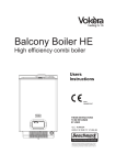
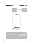
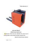
CONTENTS
WARNINGS
Pay Attention to These Terms
For your safety read before operating
4
5
COMPONENT LOCATION
General layout
Control board
6
7
GETTING STARTED
Before switching ON
Boiler controls
Lighting the boiler
Adjusting the operating temperature
Adjusting the hot water temperature
How to top-up the system pressure
How to reset the boiler
8
8
8
8
8
9
9
BOILER FAULT CODES
How to shut down the system for short periods
How to shut down the system for long periods
How to care for the boiler
9
9
9
WHAT IF...
What if I suspect a gas leak
What if I have frequently have to top-up the system
What if the red light is ON
What if the boiler is due its annual service
What if I need to call a service technician
10
10
10
10
10
MAINTENANCE
Suggested Minimum Maintenance Schedule
Preventive Maintenance Schedule
10
11
3
WARNINGS
Pay Attention to These Terms
DANGER:
Indicates the presence of immediate hazards which will cause severe personal injury, death or substantial property
damage if ignored.
WARNING:
Indicates the presence of hazards or unsafe practices which
could cause severe personal injury, death or substantial
property damage if ignored.
CAUTION:
Indicates the presence of hazards or unsafe practices which
could cause minor personal injury or product or property
damage if ignored.
NOTE:
Indicates special instructions on installation, operation, or
maintenance which are important but not related to personal
injury hazards.
DANGER: Make sure the gas on which the boiler will operate
is the same type as that specified on the boiler rating plate and
on the colored sticker near the boiler gas connection.
WARNING: Should overheating occur or the gas supply valve
fail to shut, do not turn off or disconnect the electrical supply to
the boiler. Instead, shut off the gas supply at the manual valve
directly below the boiler.
WARNING: Do not use this boiler if any part has been under
water. Immediately call a qualified service technician to inspect
the boiler and to replace any part of the control system and any
gas control which has been under water.
WARNING: To minimize the possibility of improper operation,
serious personal injury, fire, or damage to the boiler:
• Always keep the area around the boiler free of combustible
materials, gasoline, and other flammable liquids and vapors.
• Boiler should never be covered or have any blockage to the
flow of fresh air to the boiler.
WARNING: Risk of electrical shock. More than one disconnect
switch may be required to de-energize the equipment before
servicing.
WARNING - CALIFORNIA PROPOSITION 65:
This product contains chemicals known to the State of
California to cause cancer, birth defects or other reproductive
harm.
WARNING: Improper installation, adjustment, alteration, service
or maintenance can cause property damage, personal injury,
exposure to hazardous materials* or loss of life. Review the
information in this manual carefully. *This unit contains materials
that have been identified as carcinogenic, or possibly
carcinogenic, to humans.
NOTE: This manual should be maintained in legible condition
and kept adjacent to the boiler or in another safe place for
future reference.
4
AVERTISSEMENT: En cas de surchauffe ou de non fermeture
de la vanne d’alimentation en gaz, n’éteignez ou ne débranchez
pas l’alimentation électrique de la chaudière. Coupez plutôt
l’alimentation en gaz à l’extérieur de la chaudière.
AVERTISSEMENT: N’utilisez pas cette chaudière si une partie
de celle-ci s’est retrouvée sous l’eau. Appelez immédiatement
un technicien de service qualifié pour inspecter la chaudière et
pour remplacer toute partie du système de contrôle et toute
commande de gaz s’étant retrouvée sous l’eau.
AVERTISSEMENT: Une mauvaise installation, réglage,
altération, révision ou entretien peut provoquer des dommages
matériels, des blessures, l’exposition à des matières
dangereuses* ou la mort. Examinez attentivement les
informations dans cette notice. *Cette unité contient des matières
qui ont été identifiées comme étant cancérigènes, ou
éventuellement cancérigènes, chez l’homme.
TO TURN OFF GAS TO APPLIANCE
to OPEN
Gas Valve CLOSED
If you then smell gas, STOP! Follow "B"
in the safety information above this label.
If you don't smell gas, go to next step.
8. Turn gas shutoff valve counterclockwise
to open valve. Handle will be parallel to
pipe.
9. Install top cover.
10. Turn on all electric power to appliance.
11.Set thermostat to desired setting.
12.If the appliance will not operate, follow
the instructions "To Turn Off Gas To
Appliance" and call your service
technician or gas supplier.
1. Set the thermostat to lowest setting. 4. Turn gas shut off valve clockwise to close
valve. Handle will be perpendicular to pipe.
2. Turn off all electric power to the appliance
Do not force.
if service is to be performed.
5. Install top cover.
3. Remove top cover.
to CLOSE
Gas Valve OPEN
1. STOP! Read the safety information above
on this label.
2. Set the thermostat to lowest setting.
3. Turn off all electric power to the appliance.
4. This appliance is equipped with an
ignition device which automatically lights
the burner. Do not try to light the burner
by hand.
5. Remove top cover.
6. Turn gas shutoff valve clockwise to close
valve. Handle will be perpendicular to
pipe. Do not force.
7. Wait five (5) minutes to clear out any gas.
OPERATING INSTRUCTIONS
If you cannot reach your gas supplier,
call the fire department.
Use only your hand to turn the gas control
knob. Never use tools. If the handle will
not turn by hand, don't try to repair it,
call a qualified service technician. Force
or attempted repair may result in a fire
or explosion.
Do not use this appliance if any part has
been under water. Immediately call a
qualified service technician to inspect the
appliance and to replace any part of the
control system and any gas control which
has been under water.
pour
ouvrir
vanne gaz en arret
l'étape "B" des instructions de sécurité
sur la portion supérieure de cette
étiquette. S'il n'y a pas d'odeur de gaz,
passez à l'étape suivante.
8. Tourner le bouton de commande de
gaz dans le sense antihoraire à la
position "marche" (ON)
9. Remontez le couvercle du haut
10. Mettez l'appareil sous tension
11. Réglez le thermostat à la température
désirée
12. Si l'appareil ne se met pas en marche,
suivez les instructions intitulées
"Comment couper l'admission de gaz
de l'appareil" et appelez un technicien
qualifié ou le fournisseur de gaz.
1. Réglez le thermostat à la température la 4. Tournez le bouton de commande de gaz
dans le sens horaire à la position "arret"
plus basse
2. Coupez l'alimentation électrique de 5. Remontez le couvercle du haut.
l'appareil s'il faut procéder à l'entretien
3. Retirez le couvercle
Cod. 20003235
COMMENT COUPER L'ADMISSION DE GAZ L'APPAREIL
pour
fermer
vanne gaz en marche
1. ARRÊTEZ! Lisez les instructions de
sécurité sur la portion supérieure de cette
étiquette
2. Réglez le thermostat à la température la
plus basse
3. Coupez l'alimentation électrique de
l'appareil
4. Cet appareil ne comporte pas de
veilleuse. Il est muni d'un dispositif
d'allumage qui allume automatiquement
le bruleur. Ne tentez pas d'allumer le
bruleur manuallement.
5. Retirez le couvercle du haut
6. Tournez le bouton de la vanne de gaz
dans le sens horaire à la position "arret"
(OFF)
7. Attendre cinq (5) minutes pour laisser
échapper tout le gaz. Si vous sentez une
odeur de gaz, ARRÊTEZ! Passez à
INSTRUCTIONS D'ALLUMAGE
AVERTISSEMENT: Quiconque ne respecte pas à la lettre les instructions dans la
présente notice risque de déclencher un incendie ou une explosion entraînant des
dommages, des blessures ou la mort.
A.Cet appareil ne comporte pas de veilleuse.
instructions du fornisseur
Il est muni d'un dispositif d'allumage qui - Si vous ne pouvez rejoindre le
allume automatiquement le brûleur. Ne
fournisseur, appelez le service des
tentez pas d'allumer le brûleur
incendies.
manuellement.
C. Ne poussez ou tournez la manette
B. AVANT DE FAIRE FONCTIONNER, reniflez
d'admission du gaz qu'à la main; ne
tout autour de l'appareil pour déceler une
jamais utiliser d'outil. Si la manette reste
odeur de gaz. Reniflez près du plancher,
coincée, ne pas tenter de la réparer;
car certains gaz sont plus lourds que l'air
appelez un technicien qualifié. Le fait de
et peuvent s'accumuler au niveau du sol.
forcer la manette ou de la réparer peut
QUE FAIRE SI VOUS SENTEZ UNE ODEUR
déclencher une explosion ou un incendie.
DE GAZ:
D. N'utilisez pas cet appareil s'il a été plongé
- Ne pas tenter d'allumer l'appareil
dans l'eau, même partiellement. Faites
- Ne touchez à aucun interrupteur; ne pas
inspecter l'appareil par un technicien
vous servir des téléphones se trouvant
qualifié et remplacez toute partie du
dans le bâtiment
système de contrôle et toute commande
- Appelez immédiatement votre fournisseur
qui ont été plongés dans l'eau.
de gaz depuis un voisin. Suivez les
WARNING: If you do not follow these instructions exactly, a fire or explosion
may result causing property damage, personal injury, or loss of life.
A. This appliance does not have a pilot. It is equipped with an ignition device
which automatically lights the burner. Do C.
not try to light the burner by hand.
B. BEFORE OPERATING smell all around
the appliance area for gas. Be sure to
smell next to the floor because some
gas is heavier than air and will settle on
the floor.
D.
WHAT TO DO IF YOU SMELL GAS
- Do not try to light any appliance.
- Do not touch any electric switch; do not
use any phone in your building.
- Immediately call your gas supplier from
a neighbor's phone.
Follow the gas supplier's instructions.
POUR VOTRE SÉCURITÉ LISEZ AVANT DE METTRE EN MARCHE
FOR YOUR SAFETY READ BEFORE OPERATING
For your safety read before operating
Pour votre sécurité lisez avant de mettre
en marche
5
COMPONENT LOCATION
XPak 85
General layout (fig. 1)
1
2
3
4
5
6
7
8
9
10
11
12
13
14
15
16
17
18
19
20
21
22
23
24
25
26
27
R
F
G
P
C
Water pressure switch
Pump
Bottom auto air vent (AAV)
Gas injector
Condense trap
Return sensor
H stamp main heat exchanger
Main heat exchanger
Flue thermostat
Flue sensor
Flue gas analysis test point
Flue outlet & air intake
Blocked flue switch
Top automatic air vent
Flow sensor
High limit thermostat
Ignition transformer
Sensing Electrode
Spark Electrode
Top automatic air vent drain pipe
Condensate level sensor
Cylindric Burner
Fan assembly
Mixer
Gas modulator coil
Gas valve
Pressure relief valve
Boiler IN connection
Boiler OUT connection
Gas connection
Pressure relief valve drain
Condensate drain pipe
R
F
G
P
C
XPak 120
R
F
G
Fig. 1
6
P
C
Control board
Fig. 2
A
B
C
G
A
B
C
D
E
F
G
E
D
F
Pressure gauge
Green led
2-digit LED display
Red led
Temperature selector space heating
Mode selector switch
Temperature selector Domestic Hot Water
Off/reset - Select this position when the boiler needs to be
reset or switched off.
Summer mode - The domestic hot water function provided
by the water tank is activated. The display indicates the
storage tank temperature (only with the external water tank
connected with a sensor).
Winter mode - The boiler produces hot water for heating
and, if connected to an external water tank, it provides
domestic hot water. The display indicates the boiler flow temperature.
F
Winter mode tank temperature - The boiler produces hot
water for heating and, if connected to an external water tank
with a sensor, it provides domestic hot water. The display
indicates the storage tank temperature.
Temperature selector DHW- Move the temperature selector
clockwise to increase the hot water temperature in the water
tank or counter-clockwise to reduce the temperature (working
only if a tank sensor is connected).
Temperature selector Heating - Move the temperature
selector clockwise to increase the heating temperature or
counterclockwise to reduce the temperature.
2-digit LED display - Displays the temperature according
the mode selector switch. During a fault condition, the
appropriate code will be displayed (refer to the installation
instructions regarding fault codes).
Green LED lit - Boiler is working/responding to a heating/
tank request (flame ON).
Red LED lit - Boiler has identified a fault and has shut down.
Refer to installation instructions on how to reset.
Pressure gauge - Ensure the system pressure is set
correctly (minimum 7 p.s.i. (0.45 bar))
7
GETTING STARTED
Before switching ON
Before switching the boiler on please familiarize yourself with:
- how to isolate the boiler from the gas, water, and electricity
supplies;
- how to check and top-up – if necessary – the system water
pressure;
- the time clock or programmer;
- any external thermostats and their functions;
- the boiler controls.
How to read the display temperature Fig. 3)
● (dot in the middle) = means hundred (Fig. 3)
● (dot on RIGHT side) = means DHW mode (Fig. 3a)
example:
Fig. 3
Heating mode
60°F
160°F
DHW mode
Fig. 3a
Boiler controls (see Fig. 2)
The boiler controls are situated on the lower front of the boiler. The
boiler controls include:
- Pressure gauge
- Green led (burner ON)
- 2-digit LED display
- Red led (fault indicator)
- Temperature selector space heating
- Mode selector switch
- Temperature selector Domestic Hot Water
The pressure gauge shows the current pressure of your heating
system, the gauge should be typically set between 15-22 psi (11.5 bar). When the boiler is operating the gauge may rise or fall
slightly, this is quite normal. The minimum permissible level for the
safe and efficient operation of the boiler is 7 psi (0.45 bar). Should
the pressure fall below 7 psi (0.45 bar), the boiler may lockout.
The boiler mode selector is used to switch the boiler to the
various operating modes:
OFF/RESET
Summer mode
Winter mode
F
Winter mode tank temperature
NOTE
THE BOILER FREEZE PROTECTION IS ACTIVE IN ALL OF
THE ABOVE MODES.
40°F
140°F
NOTICE:
For temperature over 199°F (93°C) the display shows
.
When the status indicator (Green) is lit it indicates that the flame
is detected and the burner is fully in ON status.
When the fault indicator (Red) is lit it indicates that the boiler has
identified a possible fault and performed a safety shut-down.
Lighting the boiler
Ensure the gas and electrical supply to the boiler are turned on.
When power is restored to the boiler and/or the boiler is powered
for the first time, the boiler start a series of checking and on the
display appears a series of letters and numbers. If the checking
is ok, the boiler start an automatic purge cycling for 2 minutes, the
display will show as per Fig. 4.
After this cycling the boiler is ready to be used.
Turn the mode selector switch to the ON position. When there is
a request for heating or hot water, the boiler will begin an ignition
sequence. When the boiler reaches the set temperature, the
burner will go off for a minimum period of approximately 3 minutes.
WHEN THE ROOM THERMOSTAT HEATING REQUEST HAS
BEEN SATISFIED, THE BOILER WILL SWITCH OFF
AUTOMATICALLY.
Fig. 4
The temperature selector DHW
can be used to adjust the
temperature of the water in the storage tank. The temperature
range is adjustable between 95°F and 140°F (35°C and 60°C)
for the tank storage temperature.
can be used to adjust the
The temperature selector CH
temperature of the radiators or floor heating. The temperature
range is adjustable between 104°F and 176°F (40°C and 80°C)
for standard heating systems.
Moreover if floor heating mode is selected (by using the relative
jumper), the temperature range for heating mode can be modified
between 68°F and 113°F (20°C and 45°C).
The 2-digit LED display normally shows the operating temperature of the boiler (or storage tank temperature if fitted and the mode
selector in the proper position), however it can also display
additional characters or flashing numbers to signify specific
operating modes or fault codes.
Adjusting the operating temperature
Rotate the temperature selector – clockwise to increase, counterclockwise to decrease – to the desired temperature setting. The
temperature can be set between 104°F and 176°F (40°C and
80°C) standard heating systems and between 68°F and 113°F
(20°C and 45°C) under-floor heating systems.
NOTE
If the boiler fails to ignite during the ignition sequence, it will enter
a lockout condition. Should this occur, please allow a period of at
least two minutes before resetting the boiler.
Adjusting the hot water temperature
Rotate the temperature selector – clockwise to increase, counterclockwise to decrease – to the desired temperature setting. The
storage temperature can be set from a minimum of 95°F (35°C)
to a maximum of 140°F (60°C) if the tank has a temperature
sensor; in the case of a tank with thermostat the storage temperature is set directly on the tank thermostat.
8
How to top-up the system pressure (Fig. 5-6)
The system pressure must be checked periodically to ensure the
correct operation of the boiler. The needle on the gauge should
be reading between 15-22 psi (1-1.5 bar) when the boiler is in an
off position and has cooled to room temperature. If the pressure
requires ‘topping-up’ use the following instructions as a guide.
- Locate the filling valve connections (usually beneath the boiler,
see Fig. 5).
- Attach the filling loop to both connections (if available).
- Open the filling valve slowly until you hear water entering the
system.
- Close the filling valve when the pressure gauge (on the boiler)
reads between 15-22 psi (1-1.5 bar)
- Remove the filling loop from the connections.
BOILER FAULT CODES
CODE
ACTION REQUIRED
AL10 Reset boiler. Call service technician if fault re-occurs
AL20 Reset boiler. Call service technician if fault re-occurs
AL21 Reset boiler. Call service technician if fault re-occurs
AL26 Reset boiler. Call service technician if fault re-occurs
AL28 Reset boiler. Call service technician if fault re-occurs
AL29 Reset boiler. Call service technician if fault re-occurs
AL34 Reset boiler. Call service technician if fault re-occurs
AL40 Check system pressure and refill if necessary.
Reset boiler. Call service technician if fault re-occurs
control
valve
temporary
connection
control
valve
AL41 Check system pressure and refill if necessary.
Call service technician if fault re-occurs
AL52 Call service technician
AL55 Call service technician
AL60 Call service technician
AL71 Call service technician if fault re-occurs
flow/return
pipe
AL73 Call service technician if fault re-occurs
double
check valve
Fig. 5
supply
pipe
AL74 Reset boiler. Call service technician if fault re-occurs
AL79 Reset boiler. Call service technician if fault re-occurs
AL91 Main heat exchanger needs cleaning. Call service
technician
correct
pressure
value
IMPORTANT
If the boiler requires to be reset frequently, it may be indicative of
a fault, please contact your installer or Raypak Customer Services
for further advice.
How to shut down the system for short
periods
The system and boiler can be shut down for short periods by
simply turning the mode selector switch to the off position. It is also
advisable to turn off the main water supply to the house.
Fig. 6
How to reset the boiler
When the red fault LED is illuminated, the boiler will need to be
reset manually. Before resetting the boiler, check what action is
required to be taken, using the information on the fault code table
below. Allow a period of two minutes to elapse before rotate the
status mode knob. To reset the alarm, the status mode knob must
be rotated to the OFF position.
How to shut down the system for long
periods
If the house is to be left unoccupied for any length of time –
especially during the winter – the system should be thoroughly
drained of all water. The gas, water, and electricity supply to the
house should also be turned off. For more detailed advice contact
your installer.
How to care for the boiler
To clean the outer casing use only a clean damp cloth. Do not
use any scourers or abrasive cleaners. Damage to the cabinet
finish may occur.
9
WHAT IF...
MAINTENANCE
What if I suspect a gas leak
Suggested
Schedule
If you suspect a gas leak, turn off the gas supply at the gas meter
and contact your installer or local gas supplier. If you require
further advice please contact your nearest Raypak office.
Regular service by a qualified service agency and maintenance
must be performed to ensure maximum operating efficiency.
Maintenance as outlined below may be performed by the owner.
What if I have frequently have to top-up
the system
Daily
1. Check that the area where the heater is installed is free from
combustible materials, gasoline, and other flammable vapors
and liquids.
2. Check for and remove any obstruction to the flow of
combustion or ventilation air to boiler.
If the system regularly requires topping-up, it may be indicative of
a leak. Please contact your installer and ask him to inspect the
system.
What if the red light is ON
If the Red LED light is illuminated, it indicates that the boiler has
failed to ignite or has detected a possible fault. When this happens
the boiler automatically shuts down and requires a manual reset.
What if the boiler is due its annual service
Advice for tenants only
Your landlord should arrange for servicing.
Advice for homeowners
Please contact Raypak Customer Service if you would prefer a
Raypak service engineer or agent to service your boiler.
Alternatively your local registered service agency may be able to
service the boiler for you.
What if I need to call a service technician
If you think your boiler may have developed a fault, please contact
your installer or Raypak Customer Services. Have all your details
in hand including full address, relevant contact numbers, and your
complete boiler serial number.
Minimum
Maintenance
Monthly
1. Check for piping leaks around fittings.
If found, repair at once. DO NOT use petroleum-based stopleak compounds.
2. Visually inspect venting system for proper function,
deterioration or leakage.
3. Visually inspect for proper operation of the condensate drains
on the boiler and in the venting. If leaks are observed repair at
once.
4. Check air vents for leakage.
Yearly (Beginning of Each Heating Season)
WARNING: Annual service should ONLY be performed by a
qualified service agency. Schedule annual service by calling a
qualified service agency.
1. Visually check top of vent for soot. Call service person to clean.
Some sediment at bottom of vent is normal.
2. Visually inspect all flue product carrying areas of the boiler
including the venting system and main burner for proper
function, deterioration or leakage. Ensure that condensate
drains are inspected and ensure that condensate is being
directed to appropriate condensate management system or
drain, as required by local codes.
3. Check that area is free from combustible materials, gasoline,
and other flammable vapors and liquids.
4. Check for and remove any obstruction to the flow of
combustion or ventilation air to heater.
5. Follow pre-start-up check in the Start-up section.
6. Check operation of safety devices. Refer to manufacturers’
instructions.
7. To avoid potential of severe burn, DO NOT REST HANDS ON
OR GRASP PIPES. Use a light touch; return piping will heat
up quickly.
8. Check blower and blower motor.
9. Check for piping leaks around pumps, relief valves and other
fittings. Repair, if found. DO NOT use petroleum-based stopleak.
Periodically
1. Check relief valve. Refer to manufacturer’s instructions on
valve.
10
Preventive Maintenance Schedule
WARNING: Preventative maintenance should ONLY be
performed by a qualified service agency in accordance with
the procedures listed in the heater Installation and Operating
Instruction Manual.
The following procedures are recommended and are good
practice for all XPak installations.
Daily
1. Check gauges, monitors and indicators.
2. Check instrument and equipment settings.
Monthly
1. Check flue, vent, stack, or outlet dampers.
Semi-Annually
1. Recalibrate all indicating and recording gauges.
2. Check flame failure detection system components.
3. Check piping and wiring of all interlocks and shutoff valves.
Annually
1. Test flame failure detection system.
2. Test high limit and operating temperature.
3. Check flame sensor.
4. Conduct a combustion test at full fire. Carbon dioxide
should be 8.5% at full fire for natural gas, and 10.0% for
propane gas. Carbon monoxide should be < 130 ppm.
5. Check for leaks at all valve fittings using a soapy water
solution (while heater is operating). Test other operating
parts of all safety shut-off and control valves and increase
or decrease settings (depending on the type of control)
until the safety circuit opens. Reset to original setting
after each device is tested.
6. Perform leakage test on gas valves.
7. Test air switch in accordance with manufacturer’s
instructions. (Turn panel switch to the “On” position until
blower is proven, then turn the switch to “Off”).
8. The combustion blower motor does not require lubrication
for proper operation. DO NOT attempt to oil the motor or
damage may occur.
As Required
1. Check drip leg and gas strainers.
2. Check flame failure detection system.
3. Check igniter.
4. Check flame signal strength.
5. Test safety/safety relief valves in accordance with ASME
Heater and Pressure Vessel Code Section IV.
6. Alarm 91 (AL91) the main heat exchanger need cleaning
11
www.raypak.com
Raypak, Inc., 2151 Eastman Avenue, Oxnard, CA 93030 (805) 278-5300 Fax (805) 278-5468