1
66
2:1(560$18$/
,1&+9$5,$%/(
63(('6&52//6$:
$VVHPEO\
2SHUDWLRQ
5HSDLU3DUWV
48(67,21625&200(176"
&$//5,'*,'
ZZZULGJLGZRRGZRUNLQJFRP
Part No. SP6141
)RU<RXU6DIHW\
5HDGDOOLQVWUXFWLRQVFDUHIXOO\
Printed in U.S.A.
Table of Contents
Section
Page
Safety Instructions for Scroll Saw .......... 2
Safety Signal Words ........................... 2
Before Using The Saw ........................ 2
When Installing or Moving The Saw ... 3
Before Each Use ................................. 3
Plan Ahead To Protect Your Eyes,
Hands, Face and Ears ....................... 4
Whenever Saw Is Running ................. 5
Before Leaving the Saw ...................... 6
Glossary of Terms for Woodworking ..... 6
Motor Specifications and Electrical
Requirements .................................... 6
Power Supply and Motor
Specifications .................................... 6
General Electrical Connections .......... 6
110-120 Volt, 60 Hz. Tool
Information ........................................ 7
Wire Sizes ........................................... 8
Unpacking and Checking Contents .... 9
Tools Needed ..................................... 9
Unpacking ........................................... 9
List of Loose Parts .............................. 9
Getting to Know Your Scroll Saw ......... 10
Alignment (Adjustments) ...................... 12
Changing the Table Bevel Angle ...... 12
To Align the Bevel Indicator .............. 12
Adjusting Work Hold-down ............... 13
Over Tensioning Or Under
Tensioning Blade ............................. 13
Section
Page
Removing Pin End Blades ................ 14
Installing Pin End Blades .................. 15
Removing Plain End Blades ............. 16
Installing Plain End Blades ............... 17
Dust Blower ...................................... 18
Blade Guard ..................................... 18
Sawdust Collection Port ................... 18
Mounting the Scroll Saw ...................... 18
Workbench Applications ................... 18
Safety Instructions for Basic Saw
Operations ....................................... 19
Before Each Use .............................. 19
Plan Ahead To Protect Your Eyes,
Hands, Face And Ears .................... 19
Whenever Saw Is Running ............... 20
Before Leaving The Saw: ................. 21
Basic Saw Operations ......................... 21
General Instructions ......................... 21
Making Interior Scroll Cuts ............... 21
Choice of Blade and Speed .............. 22
Maintenance ........................................ 23
General ............................................. 23
Motor/Electrical ................................. 23
Arm Bearings .................................... 23
Troubleshooting ................................... 24
Wiring Diagram .................................... 25
Repair Parts ........................................ 26
Safety Instructions for Scroll Saw
Safety is a combination of common
sense, staying alert and knowing how
your scroll saw works. Read this manual
to understand this saw.
Safety Signal Words
DANGER: means if the safety information
is not followed someone will be seriously
injured or killed.
WARNING: means if the safety information is not followed someone could be
seriously injured or killed.
CAUTION: means if the safety information is not followed someone may be
injured.
Before Using The Saw
WARNING: To reduce the risk of
mistakes that could cause serious
permanent injury, do not plug the
saw in until the following steps are
completed.
• Completely assemble and align saw
(see “Assembly and Alignment” sections
within).
2
• Learn the use and function of the speed
control ON-OFF knob, bevel lock knob,
blade holders, blade support, hold down,
tension knob, and blade guard. (See “Getting to Know Your Scroll Saw” section.)
• Review and understand all safety
instructions and operating procedures in
this manual.
• Review the maintenance methods for
this saw. (See “Maintenance” section.)
• Read the warning label below, which is found on the base of the saw.
When Installing or Moving The Saw
To Reduce the Risk of Dangerous Environment. Use the saw in a dry indoor
place, protected from rain. Keep work
area well lighted.
To reduce the risk of injury from unexpected saw movement:
• Turn saw off and unplug cord before
moving the saw.
• Place the saw on a firm level surface
where there is plenty of room for handling and properly supporting the workpiece.
• Support the saw so the table is level and
the saw does not rock.
• Bolt the saw to the work surface if it
tends to slip, walk, or slide during operations like cutting long heavy boards, or
when using an auxiliary table.
• Never Stand On Tool. Serious injury
could occur if the tool tips or you accidentally hit the cutting tool. Do not store
any item above or near the tool where
anyone might stand on the scroll saw to
reach that item.
To reduce the risk of injury or death
from electrical shock:
• Ground the saw. This saw has an
approved 3 conductor cord and a 3prong grounding type plug. Use only 3wire, grounded outlets rated 120 volts,
15 amperes (amps). The green conductor in the cord is the grounding wire. To
reduce the risk of electrocution, NEVER
connect the green wire to a live terminal.
• Make sure your fingers do not touch the
plug’s metal prongs when plugging or
unplugging the saw.
Before Each Use
• Broken parts.
• Stable mounting.
• Any other conditions that may affect the
way the saw works.
If any part is missing, bent or broken in
any way, or any electrical parts don't work
properly, turn the saw off and unplug the
saw. Replace damaged, missing or failed
parts before using the saw again. Keep
Guard In Place and in working order.
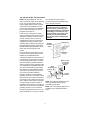
Inspect your saw.
Disconnect The Saw. To reduce the risk
of injury from accidental starting, unplug
the saw, turn the switch off and lock out
the switch before changing the setup,
removing covers, guards or blade.
Check For Damaged Parts. Check for:
• Alignment of moving parts.
• Binding of moving parts.
3
Safety Instructions for Scroll Saw (continued)
Maintain Tools with Care. Keep the saw
clean for best and safest performance. Follow instructions for lubricating.
Remove adjusting keys and wrenches
from tool before turning it on.
To reduce the risk of injury from jams,
slips or thrown pieces
• Use Only Recommended Accessories. Follow the instructions that come
with the accessories. The use of
improper accessories may cause risk of
injury to person.
• Choose the right size and style blade for
the material and the type of cutting you
plan to do.
• Make sure the blade teeth point downward, toward the table.
• Make sure the blade tension is properly
adjusted.
• Keep Work Area Clean. Cluttered areas
and benches invite accidents. Floor
must not be slippery.
To reduce the risk of burns or other fire
damage, never use the saw near flammable liquids, vapors or gases.
• Know Your Saw. Read and understand
the owners manual and labels affixed to
the tool. Learn its application and limita-
tions as well as the specific potential
hazards peculiar to this tool.
• To reduce the risk of injury from accidental contact with moving parts, don't do
layout, assembly, or setup work on the
saw while any parts are moving.
• Reduce the Risk of Accidental Starting. Make sure switch is "OFF" before
plugging saw into a power outlet.
Plan Your Work.
• Use The Right Tool. Don't force tool or
attachment to do a job it was not
designed for.
• Use this scroll saw to cut only wood,
woodlike products, plastics and nonferrous metals.
CAUTION: This saw is NOT
designed for cutting ferrous metals
like iron or steel. When cutting nonferrous metals (brass, copper and
aluminum, etc.), metal shavings can
react with wood dust and start a fire.
To reduce the risk of fire:
• Remove all traces of wood dust
from on and around the saw.
• Remove all metal shavings from on
or around the saw before sawing
wood again.
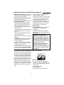
Plan Ahead To Protect Your Eyes, Hands, Face and Ears
Any power saw can throw foreign objects
into the eyes. This can cause permanent
eye damage. Always wear safety goggles,
not glasses, complying with ANSI Z87.1
(or in Canada CSA Z94-3-M88) shown on
package. Everyday eyeglasses have only
impact resistant lenses. They are not
safety glasses. Safety goggles are available at many local retail stores. Glasses
or goggles not in compliance with ANSI or
CSA could seriously hurt you when they
break.
Dress for safety
• Do not wear loose clothing, gloves,
neckties or jewelry (rings, wristwatches).
They can get caught and draw you into
moving parts.
• Wear nonslip footwear.
• Tie back long hair.
• Roll long sleeves above the elbow.
4
• Noise levels vary widely. To reduce the
risk of possible hearing damage, wear
ear plugs or muffs when using saw for
hours at a time.
• For dusty operations, wear a dust mask
along with the safety goggles.
Inspect Your Workpiece.
Make sure there are no nails or foreign
objects in the part of the workpiece to be cut.
Use extra caution with large, very
small or awkward workpieces
• Never use this tool to finish pieces too
small to hold by hand.
• Use extra supports (tables, saw horses,
blocks, etc.) for any workpieces large
enough to tip when not held down to the
table top.
• Never use another person as a substitute for a table extension, or as additional support for a workpiece or to help
feed, support or pull the workpiece.
• When cutting irregularly shaped workpieces, plan your work so it will not pinch
the blade. A piece of molding, for example, must lay flat or be held by a fixture
or jig that will not let it twist, rock or slip
while being cut.
• Properly support round material such as
dowel rods or tubing. They have a tendency to roll during a cut, causing the
blade to “bite”. To avoid this, always use
“V” blocks.
• Cut only one workpiece at a time.
• Clear everything except the workpiece
and related support devices off the table
before turning the saw on.
Plan the way you will hold the workpiece from start to finish.
• Do not hand hold pieces so small that
your fingers will go under the blade
guard. Use jigs or fixtures to hold the
work and keep your hands away from
the blade.
• Reduce the Risk of awkward operations
and hand positions where a sudden slip
could cause fingers or hand to move into
the blade.
• Don’t Overreach. Keep good footing
and balance.
• Keep your face and body to one side of
the blade, out of line with a possible
thrown piece if the blade should break.
Whenever Saw Is Running
WARNING: Don’t let familiarity
(gained from frequent use of your
scroll saw) cause a careless mistake.
A careless fraction of a second is
enough to cause a severe injury.
Before Freeing Any Jammed Material.
• Turn switch “OFF”
• Wait for all moving parts to stop.
• Unplug the saw.
When backing up the workpiece, the
• Before starting your cut, watch the saw
blade may bind in the kerf (cut). This is
while it runs. If it makes an unfamiliar
usually caused by sawdust clogging
noise or vibrates excessively, stop imme- up the kerf. If this happens:
diately. Turn the saw off. Unplug the saw.
• Turn switch “OFF”.
Do not restart until finding and correcting
• Wait for all moving parts to stop.
the problem.
• Keep Children Away. Keep all visitors a • Unplug the saw.
• With a flat blade screwdriver, turn motor
safe distance from the saw. Make sure
shaft by hand. Insert the screwdriver into
bystanders are clear of the saw and
the slotted end of motor shaft located at
workpiece.
the center of the motor housing. Do this
• Don’t Force Tool. It will do the job better
while backing up the workpiece.
and safer at its designed rate. Feed the
Before removing loose pieces from the
workpiece into the saw blade only fast
enough to let it cut without bogging down table, turn saw off and wait for all moving parts to stop.
or binding.
5
Safety Instructions for Scroll Saw (continued)
Before Leaving the Saw
knob on the saw. Store the key away from
children and others not qualified to use
the tool.
• Wait for all moving parts to stop.
• Make Workshop Child-proof. Unplug
the saw. Lock the workshop and ON/OFF
Glossary of Terms for Woodworking
Kerf - the slot cut by the blade.
Leading Edge - the edge of the workpiece which is pushed into the blade first.
Sawblade Path - the area of the workpiece directly in line with and moving
toward the sawblade edge.
Bevel - the ability to slant the table to
make angle cuts. An angle cutting opera-
tion through the face of the board.
Blade Tooth Set - the distance that the
edge of the sawblade tooth is bent (or set)
outward from the side of the blade.
Trailing Edge - the workpiece edge last
cut by the sawblade.
Workpiece - the item on which the cutting
operation is being performed.
Motor Specifications and Electrical Requirements
Power Supply and Motor Specifications
CAUTION: A direct current motor is
WARNING: To reduce the risk of
electrical hazards, fire hazards or
damage to the tool, use proper circuit
protection. Your tool is wired at the
factory for operation using the voltage shown. Connect tool to a power
line with the appropriate voltage and
a 15-amp branch circuit. Use a 15amp time delay type fuse or circuit
breaker. To reduce the risk of shock
or fire, if power cord is worn or cut, or
damaged in any way, have it replaced
immediately.
used in this saw. Changes to the
internal wiring will create a fire hazard and may also create a shock hazard.
This machine is equipped with a variable
speed motor having the following specifications:
Voltage
For replacement motor and control board,
refer to parts list in this manual.
110-120
Amperes
1.2
Hertz (Cycles)
60
Phase
Single
RPM
500-1700
Rotation of Shaft Clockwise
General Electrical Connections
WARNING: Do not permit fingers to
DANGER: To reduce the risk of
electrocution:
• Use only identical replacement
parts when servicing. Servicing
should be performed by a qualified
service technician.
• Do not use in rain or where floor is
wet.
This tool is intended for indoor residential use only.
touch the terminals of plug when
installing or removing the plug to or
from the outlet.
If power cord is worn or cut, or damaged
in any way, have it replaced immediately.
6
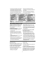
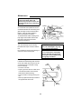
110-120 Volt, 60 Hz. Tool Information
NOTE: The plug supplied on your tool
may not fit into the outlet you are planning
to use. Your local electrical code may
require slightly different power cord plug
connections. If these differences exist
refer to and make the proper adjustments
per your local code before your tool is
plugged in and turned on.
In the event of a malfunction or breakdown, grounding provides a path of least
resistance for electric current to reduce
the risk of electric shock. This tool is
equipped with an electric cord having an
equipment grounding conductor and a
grounding plug, as shown. The plug must
be plugged into a matching outlet that is
properly installed and grounded in accordance with all local codes and ordinances.
Do not modify the plug provided. If it will
not fit the outlet, have the proper outlet
installed by a qualified electrician.
A temporary adapter may be used to connect this plug to a 2-pole outlet, as shown,
if a properly grounded outlet is not available. This temporary adapter should be
used only until a properly grounded outlet
can be installed by a qualified electrician.
The green colored rigid ear, lug and the
like, extension from the adapter must be
connected to a permanent ground such
as a properly grounded outlet box.
Improper connection of the equipment
grounding conductor can result in a risk of
electric shock. The conductor with insulation having an outer surface that is green
with or without yellow stripes is the equipment grounding conductor. If repair or
replacement of the electric cord or plug is
necessary, do not connect the equipmentgrounding conductor to a live terminal.
If the grounding instructions are not completely understood, or if you are in doubt
as to whether the tool is properly
grounded check with a qualified electrician or service personnel.
WARNING: If not properly
grounded, this tool can cause an
electrical shock, particularly when
used in damp locations, in proximity
to plumbing, or out of doors. If an
electrical shock occurs there is the
potential of a secondary hazard,
such as your hands contacting the
sawblade.
3-Prong Plug
Properly
Grounded
Outlet
Grounding
Prong
Make sure this
Is Connected
to a Known
Ground
Green
Grounding Lug
3-Prong
Plug
2-Prong
Outlet
Adapter
NOTE: The adapter illustrated is for use
only if you already have a properly
grounded 2-prong outlet.
NOTE: Use of a temporary adapter is not
permitted by the Canadian Electrical
Code.
7
Motor Specifications and Electrical Requirements (continued)
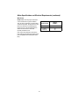
Wire Sizes
NOTE: Make sure the proper extension
cord is used and is in good condition.
The use of any extension cord will cause
some loss of power. To keep this to a minimum and to prevent overheating and
motor burn-out, use the table shown to
determine the minimum wire size
(A.W.G.) extension cord.
Use only 3-wire extension cords which
have 3-prong grounding type plugs and 3pole receptacles which accept the tools
plug.
Extension
Cord Length
Gauge
(A.W.G.)
110-120V
0-25 Ft.
26-50 Ft.
8
18
16
Unpacking and Checking Contents
Tools Needed
Medium Standard and
Phillips Screwdriver
Combination Square
Unpacking
NOTE: Hardware to mount this scroll saw
to a bench is not supplied. See mounting
instructions for recommended hardware
size.
WARNING: To reduce the risk of
injury, from unexpected starting or
electrical shock, do not plug the
power cord into a power source outlet
during unpacking and assembly. This
cord must remain unplugged whenever you are working on the saw.
Do Not Lift Saw By This Arm
A
Your scroll saw is fully assembled and
shipped complete in one box.
IMPORTANT: Never lift this saw by the
arm which holds the blade or damage will
occur to your saw.
Separate all parts from packaging materials and check each item with illustration
and "List of Loose Parts". Make certain all
items are accounted for before discarding
any packaging material.
NOTE: Before beginning assembly, check
that all parts are included. If you are missing any part, do not assemble the saw.
Call 1-800-4-RIDGID or E-mail us at
[email protected] to get the
missing part. Sometimes small parts can
get lost in packaging material. DO NOT
throw away any packaging until saw is put
together. Check packaging for missing
parts before contacting RIDGID. A complete parts list (Repair Parts) is at the end
of the manual. Use the list to identify the
number of the missing part.
Lift
Here
Lift Here
B
C
List of Loose Parts
Item
Description
Qty.
A 16" Scroll Saw
(Completely Assembled)................ 1
B Owner’s Manual............................. 1
C Loose Parts Bag containing:
Blade ........................................1
9
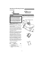
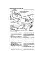
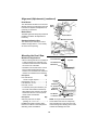
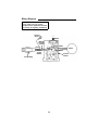
Getting to Know Your Scroll Saw
11 Height
Adjusting Knob
10 Blade Guard/Hold-Down Knob
9 Upper Blade Holder
1 Blade
Tension Knob
8 Blade Guard
Blade
Arm Bearings
7 Storage
Drawer
3 Bevel Scale
Frame
(Lift Here)
2 Work Hold-Down Foot
and Blade Support
4 Bevel
Indicator
12 Sawdust
Collection
Port
5 Table Bevel
Lock Knob
Base
(Lift Here)
9 Lower Blade Holder
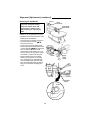
1. Blade Tension Knob - Tightening
the knob (clockwise) will increase the
tension on the blade. Loosening it
(counterclockwise) will decrease the
tension.
2. Work Hold-Down and Blade Support - Provides added control of
workpiece, protection for operator
and support for the blade.
3. Bevel Scale - Shows angle table is
tilted for bevel cutting.
4. Bevel Indicator - Points to the
approximate angle of the blade in
relation to the table top.
5. Table Bevel Lock Knob - When
tightened, this knob secures table at
desired bevel angle. Loosening knob
allows the table to tilt up to 45° for
bevel cuts.
6. Speed Control/On-Off Knob - For
speed control setting, refer to the
10
7.
8.
9.
10.
11.
12.
6 Speed Control
On/Off Knob
“Choice of Blade and Speed” table.
The On-Off knob has a locking feature, This Feature Is Intended To
Help Prevent Unauthorized Use By
Children And Others. (See more on
next page.
Storage Drawer - For convenient
storage of pin and plain blades.
Blade Guard - Defines area of moving blade.
Blade Holders - Retain and position
the blade.
Blade Guard/Hold Down Knob Allows for secure angular positioning
of blade guard, work hold down and
sawdust blower.
Height Adjustment Knob - Allows
for vertical positioning of blade guard/
hold down.
Sawdust Collection Port - Hook up
a wet/dry vac to help control sawdust.
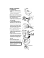
Speed Control/On-Off Knob (continued)
• To turn machine “ON”, place fingers
on Speed Control/On-Off Knob and
pull out.
• To turn machine “OFF”, push in
Speed Control/On-Off Knob.
WARNING: Never leave the machine
unattended until it has come to a
complete stop.
The variable speed control may be
adjusted to the approximate speeds identified on the control panel. Suggested
speeds are identified under “Choice of
Blade and Speed”. Turn the control knob
clockwise
to increase strokes per
minute and counterclockwise
to
reduce the strokes per minute.
• To lock knob in “OFF” position, install
a padlock through the hole below
the knob as illustrated, and lock the
padlock. (Padlock is not supplied
with the saw.)
Rotate
Speed
Control
WARNING: For your own safety,
always push the knob “Off” when
machine is not in use. Also, in the
event of a power failure (all of your
lights go out), push knob “Off”.
“Lockout” your knob with a padlock
as shown. This will prevent the
machine from starting up again
when the power comes back on.
Install
Padlock
Through Hole
5/32 to 3/16 Inch
Approximate
Diameter
1 Inch Approximate
Approximate
Padlock Size
11
Alignment (Adjustments)
Changing the Table Bevel Angle
• The scroll saw work table can be tilted to
the left for bevel cutting up to 45° from
the 0° or horizontal cutting position.
• A bevel scale and indicator are provided
under the work table as a convenient reference for setting the approximate table
angle for bevel cutting.
NOTE: A scroll saw is a scroll curve cutting tool. It is not intended for making
precise angular cuts in wood. The indicator is provided to give approximate
angular readings. A precision protractor
or square should be used to measure a
more precise blade to table angular locations.
Bevel
Scale
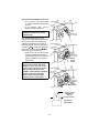
To Align the Bevel Indicator
• Loosen the table bevel lock knob and
use a small square to set the table at 90°
to the blade.
• When there is no space between the
square and the blade, hold table in place
and tighten the bevel lock knob. The
table should now be approximately 90°
to the blade.
• Loosen the screw holding the bevel
scale pointer and adjust to 0°. Tighten
screw.
Remember, the bevel scale is a convenient guide but should not be relied
upon for precision.
Bevel
Pointer
12
Bevel
Lock Knob
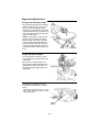
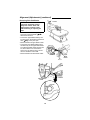
Adjusting Work Hold-down
WARNING: To reduce the risk of
injury from accidental starting,
always turn switch "OFF" and
unplug power cord from outlet
before removing or replacing the
blade.
Height Adjustment Knob
Hold-Down
Knob
The purpose of the work hold-down foot is
to hold the work against the table so that it
is less likely to lift with the up stroke of the
blade. It should lie flat on the workpiece
with the front prongs straddling the blade.
1. The work hold-down foot is attached to
the blade guard rod. The height of the
work hold-down foot is adjusted by
loosening the height adjustment knob
and moving the guide post up or down.
The work hold-down foot is adjusted
front to back and left-to-right by loosening the hold-down knob located on the
bracket, as illustrated.
2. When the table is tilted, the work holddown foot can be adjusted by loosening
the height adjustment knob and adjusting the foot to the same angle as the
table. The work hold-down foot should
always be adjusted as close to the
blade as possible without touching it
and positioned directly on the surface of
the workpiece.
NOTE: For most applications tightening
the hold down knob with your fingers is
adequate.
Over Tensioning Or Under
Tensioning Blade
Too much or too little blade tension could
cause blades to break rapidly.
The thicker, harder and more abrasive the
wood you are cutting, the more blades
you will have to use.
Adjust
Hold-Down
Foot to
Same Angle
as Table
Blade breakage is caused by the following:
• Over tension or under tension.
• Twisting or bending the blade.
• Over use - blade life exhausted.
• Over Aggressive Feeding of the workpiece into the blade by going too fast.
13
Alignment (Adjustments) (continued)
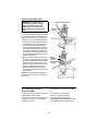
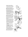
Removing Pin End Blades
Loosen
WARNING: To reduce the risk of
Blade
Tension Knob
injury from accidental starting,
always turn switch "OFF" and
unplug power cord from outlet
before removing or replacing the
blade.
Upper Blade
Holder Knob
NOTE: Saw comes with 5" pin end blade
installed. If you are going to use 5" plain
end blades, refer to the instructions under
“Installing Plain End Blades”.
• Loosen tension on blade by turning tension knob counterclockwise
about three full turns.
• Loosen upper and lower blade holder
knobs by turning the blade holder knobs
counterclockwise
about three full
turns. To make lower blade holder
access easier, tilt the table to 45°, and
raise the arms to the up position using a
screwdriver to rotate the motor shaft.
• Remove blade from the lower blade
holder by pushing down on the upper
arm, releasing the pin end blade from
the lower blade holder. Remove blade
from the upper blade holder by slightly
lifting up on the blade and pulling forward.
Loosen
Upper
Blade
Holder
Lower Blade
Holder
Loosen
Pin
14
Installing 5" Pin End Blades
Pin end blade set up:
• Check that the blade tension knob is
loose.
• Check that the upper and lower blade
holder knobs are loose. Spread blade
holder jaws open using fingers.
NOTE: A rubber band looped around the
back of the blade holder will automatically
open the jaws when the knobs are loosened which will make changing blades
easier. See illustration below.
• Install the blade through the opening in
the table with the teeth pointing down.
Engage the pin into the “V” notch of the
lower blade holder.
• Pull up on the blade and engage the
upper pin in the “V” notch of the upper
blade holder.
• Rotate the blade holders until you align
the front face of the blade holders with
the vertical edge of the blade. Tighten
upper and lower blade holder knobs by
turning knobs clockwise until the jaws
close evenly against the blade.
NOTE: To prevent blade holder damage,
do not use pliers to tighten knob.
• Carefully tighten the blade tension by
turning the tension knob clockwise
just until you feel the slack in the
blade is removed.
• Check to see that the pins are properly
located in the V-notch slot. Turn the tension knob an additional two full turns
clockwise. This amount of blade tension
should do well for most cutting operations and blades. This may vary by one
turn depending on blade thickness and
blade type.
• Make sure the blade is properly
installed. Before applying power, rotate
the motor shaft by hand using a screwdriver in the motor shaft slot as shown.
Tighten
“V”-Notch
Pin
Tighten
“V”-Notch
Tighten
Pin
WARNING: To reduce the risk of
injury from thrown objects, remove
all tools from the saw.
Rubber Band
15
Alignment (Adjustments) (continued)
Removing Plain End Blades
Loosen
WARNING: To reduce the risk of
injury from accidental starting,
always turn switch “OFF” and
unplug power cord from outlet
before removing or replacing the
blade.
• Loosen tension on blade by turning tension knob counterclockwise
about three full turns.
• Loosen the upper blade holder by turning the knob on the holder counterclockwise
so the jaws open.
• Remove blade from upper blade holder.
• Loosen the lower blade holder knob in
the same way as the upper blade holder.
To make lower blade holder access easier, tilt the table to 45° and raise the
arms to the up position using a screwdriver to rotate the motor shaft.
• Remove blade from lower blade holder.
Loosen
Lower Blade
Holder
Loosen
16
Upper
Blade
Holder
Installing 5" Plain End Blades
Tighten
• Check that the blade tension knob is loose.
• Check that the upper and lower blade
holder knobs are loose. Spread blade
holder jaws open using fingers.
NOTE: A rubber band looped around the
back of the blade holder will automatically
open the jaws when the knobs are loosened which will make changing blades
easier. See illustration below.
• Install the blade through the hole in the
table and into the lower blade holder. The
blade teeth should point down. Position the
blade so that it is straight with the front face
of the blade holder and extends beyond the
blade holder as shown.
• Tighten the lower blade holder knob by
turning the knob clockwise
until the jaws close securely.
NOTE: To maintain blade holder clamping
force, keep finger knob threads cleaned
and oiled using all purpose household
machine (or motor) oil. To prevent blade
holder damage, do not use pliers to
tighten knob.
• Use the same procedure to install the
blade into the upper blade holder. Before
tightening the jaws using the upper
blade holder knob, adjust the position of
the upper blade holder by turning the
blade tension knob until the end of the
blade is near the top of the blade holder
as shown. Tighten the upper blade
holder knob by turning the knob clockwise
until the jaws close
securely.
• Tighten the blade tension knob clockwise
until the blade is tensioned. The number of turns will be
approximately two full turns. This may
vary by one turn depending on blade
thickness and blade type.
• Make sure the blade is properly
installed. Before applying power, rotate
the motor shaft by hand using a screwdriver in the motor shaft as shown.
NOTE: To prevent blade holder damage,
do not use pliers to tighten knob.
Tighten
Position Blade
As Shown
Lower Blade
Holder
Tighten
Position Blade
As Shown
Rubber
Band
17
Upper Blade
Holder
Alignment (Adjustments) (continued)
Dust Blower
The dust blower will direct air to the most
effective point on the cutting line when the
hold down is adjusted. No adjustment is
necessary to the blower.
Blade
Guard
Blade Guard
The blade guard will always be positioned
parallel to the blade. No adjustment is
necessary.
Dust Blower
Sawdust Collection Port
Sawdust Collection
Port
The collection port will help to control
sawdust. Simply attach a 1-1/4" wet/dry
vac hose into the opening.
Mounting the Scroll Saw
Workbench Applications
• When mounting this saw to a workbench
a solid wood bench is preferred. A plywood bench will cause noise and vibration to be more noticeable.
• Hardware to mount this saw to a workbench is not supplied with the saw.
However, we recommend the hardware
used be not smaller than the following.
Description
Qty.
Hex Head Screw,
1/4-20 x length required ................. 3
Flat Washers, 1/4 I.D. ......................... 6
Lock Washers, 1/4 I.D......................... 3
Hex Nuts, 1/4-20................................. 6
• A soft foam pad to place between your
scroll saw and workbench is not supplied with the saw. However, we highly
recommend the use of such a pad to
reduce noise and vibration.
Description
Qty.
Soft foam pad such as carpet
padding, 24” x 12” x 1/2” .................. 1
Do NOT over tighten mounting bolts leave some cushion in the foam pad for
absorbing noise and vibration.
Scroll Saw Base
Top View
Hex Head Screw
Workbench
Hex Head
Screw
Flat Washer
1/2" Foam Pad
(Optional)
Workbench
Side View
Flat Washer
Lockwasher
Hex Nut
Jam Nut
NOTE: Through normal use sawdust
accumulates under the unit. Frequently
clean sawdust from under the unit to prevent the linkage from binding, which could
overload and damage the motor.
18
Safety Instructions for Basic Saw Operations
Before Each Use
• Make sure the blade tension is properly
adjusted.
• Keep Work Area Clean. Cluttered areas
and benches invite accidents. Floor
must not be slippery.
To reduce the risk of burns or other fire
damage, never use the saw near flammable liquids, vapors or gases.
• Know Your Saw. Read and understand
the owners manual and labels affixed to
the tool. Learn its applications and limitations as well as the specific potential
hazards peculiar to this tool.
• To reduce the risk of injury from accidental contact with moving parts, don't do
layout, assembly or setup work on the
saw while any parts are moving.
• Reduce the Risk of Accidental Starting. Make sure switch is “OFF” before
plugging saw into a power outlet.
Plan your work.
• Use The Right Tool. Don't force tool or
attachment to do a job it was not
designed to do.
• Use this scroll saw to cut only wood,
wood-like products, plastics and nonferrous metals.
Inspect your saw.
Disconnect The Saw. To reduce the risk
of injury from accidental starting, turn the
switch “OFF”, unplug the saw before
changing the setup, removing covers,
guards or blade.
Check Damaged Parts. Check for:
• Alignment of moving parts.
• Binding of moving parts.
• Broken parts.
• Stable mounting.
• Any other conditions that may affect the
way the saw works.
• If any part is missing, bent or broken in
any way, or any electrical parts don’t
work properly, turn the saw off and
unplug the saw. Replace damaged,
missing or failed parts before using the
saw again. Keep Guard In Place and in
working order.
Maintain Tools With Care. Keep the saw
clean for best and safest performance.
Follow instructions for lubricating.
Remove adjusting keys and wrenches
from tool before turning it on.
To reduce the risk of injury from jams,
slips or thrown pieces:
• Use Only Recommended Accessories. Follow the instructions that come
with the accessories. The use of
improper accessories may cause risk of
injury to persons.
• Choose the right size and style blade for
the material and the type of cutting you
plan to do.
• Make sure the blade teeth point downward, toward the table.
CAUTION: This saw is NOT
designed for cutting ferrous metals
like iron or steel. When cutting nonferrous metals (brass, copper and
aluminum, etc.), metal shavings can
react with wood dust and start a fire.
To reduce the risk of fire:
• Remove all traces of wood dust
from inside the saw.
• Remove all traces of metal dust
from on or around the saw before
sawing wood again.
Plan Ahead To Protect Your Eyes, Hands, Face And Ears
Any power saw can throw foreign objects
into the eyes. This can cause permanent
eye damage. Wear safety goggles, not
glasses complying with ANSI Z87.1 (or in
Canada CSA Z94-3-M88) shown on package. Everyday eyeglasses have only
impact resistant lenses. They are not
safety glasses. Safety goggles are available at many local retail stores. Glasses
or goggles not in compliance with ANSI or
CSA could seriously hurt you when they
break.
19
Safety Instructions for Basic Saw Operations (continued)
Dress for safety
• Do not wear loose clothing, gloves,
neckties or jewelry (rings, wristwatches).
They can get caught and draw you into
moving parts.
• Wear non-slip footwear.
• Tie back long hair.
• Roll long sleeves above the elbow.
• Noise levels vary widely. To reduce the
risk of possible hearing damage, wear
ear plugs or muffs when using saw for
hours at a time.
• For dusty operations, wear a dust mask
along with the safety goggles.
Inspect your workpiece.
Make sure there are no nails or foreign
objects in the part of the workpiece to be cut.
Use extra caution with large, very
small or awkward workpieces
• Never use this tool to finish pieces too
small to hold by hand.
• Use extra supports (tables, saw horses,
blocks, etc.) for any workpiece large
enough to tip when not held down to the
table top.
• Never use another person as a substitute for a table extension, or as additional support for a workpiece or to help
feed, support or pull the workpiece.
• When cutting irregularly shaped work-
pieces, plan your work so it will not pinch
the blade. A piece of molding, for example, must lay flat or be held by a fixture
or jig that will not let it twist, rock or slip
while being cut.
• Properly support round material such as
dowel rods or tubing. They have a tendency to roll during a cut, causing the
blade to "bite". To avoid this, always use
a "V" block.
• Cut only one workpiece at a time.
• Clear everything except the workpiece
and related support devices off the table
before turning the saw on.
Plan the way you will hold the workpiece from start to finish.
• Do not hand hold pieces so small that
your fingers will go under the blade
guard. Use jigs or fixtures to hold the
work and keep your hands away from
the blade.
• Reduce the Risk of awkward operations
and hand positions where a sudden slip
could cause fingers or hand to move into
the blade.
• Don’t Overreach. Keep good footing
and balance.
• Keep your face and body to one side of
blade, out of line with a possible thrown
piece if the blade should break.
Whenever Saw Is Running
WARNING: Don’t let familiarity
(gained from frequent use of your
saw) cause a careless mistake. A
careless fraction of a second is
enough to cause a severe injury.
• Before starting your cut, watch the saw
while it runs. If it makes an unfamiliar
noise or vibrates a lot, stop immediately.
Turn the saw off. Unplug the saw. Do not
restart until finding and correcting the
problem.
• Keep Children Away. Keep all visitors a
safe distance from the saw. Make sure
bystanders are clear of the saw and
workpiece.
• Don’t Force Tool. It will do the job better
and safer at its designed rate. Feed the
workpiece into the saw blade only fast
enough to let it cut without bogging down
or binding.
Before freeing any jammed material:
• Turn switch “OFF”.
• Wait for all moving parts to stop.
• Unplug saw.
When backing up the workpiece, the
blade may bind in the kerf (cut). This is
usually caused by sawdust clogging
up the kerf. If this happens:
• Turn switch “OFF”.
• Wait for all moving parts to stop.
• Unplug saw.
• With a flat blade screwdriver, turn the
motor by hand while backing up the
workpiece.
Before removing loose pieces from the
table, turn saw off and wait for all moving parts to stop.
20
Before Leaving The Saw
• Wait for all moving parts to stop.
• Make Workshop Child-proof. Unplug
the saw. Lock the workshop and ON/
OFF knob on the saw. Store the key
away from children and others not qualified to use the tool.
Basic Saw Operations
General Instructions
Please, read and understand the following items about your scroll saw before
attempting to use the saw.
• The saw does not cut wood by itself. You
allow the saw to cut wood by guiding the
wood into the blade as it moves.
• The blade teeth cut wood only on the
down stroke.
• You must guide the wood into the blade
slowly because the teeth of the blade
are very small and they can only remove
wood when they are on the down stroke.
• There is a learning curve for each person who wants to use this saw. During
that period of time it is expected that
some blades will break until you learn
how to use the saw and receive the
greatest benefit from the blades.
• Best results are achieved when cutting
wood less than one inch thick.
• When cutting wood thicker than one inch
the user must guide the wood very, very
slowly into the blade and take extra care
not to bend or twist the blade while cutting in order to maximize blade life.
• Teeth on scroll saw blades wear out and
as such must be replaced frequently for
best cutting results. Scroll saw blades
generally stay sharp for 1/2 hour to 2
hours of cutting.
• To get accurate cuts, be prepared to
compensate for blade’s tendency to follow the wood grain as you are cutting.
• This scroll saw is intended to cut wood,
wood-like products, plastics and nonferrous metals.
• When choosing a blade to use with your
scroll saw, consider the following carefully.
• Very fine, narrow blades should be
used to scroll cut in thin wood 1/4 inch
thick or less.
• To cut wood over 1/4 inch thick, use
wider blades.
• Most blade packages state the size or
thickness of wood which that blade is
intended to cut, and the radius, size of
curve, which can be cut with that
blade.
• Wider blades can’t cut curves as tight
or small as thinner blades.
• Narrower blades work well only on
thinner wood material.
• This saw uses 5 inch long pin and plain
end type blades only.
• Blades wear faster when cutting plywood, which is very abrasive; when sawing wood which is thicker than the 7/8
inch blade stroke; and when sawing
hardwood, or when side pressure is
placed on the blade.
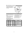
Making Interior Scroll Cuts
• One of the features of this saw is that it
can be used to make scroll cuts on the
interior of a board without breaking or
cutting into the outline or perimeter of
the board.
WARNING: To reduce the risk of
injury from accidental starting,
always turn switch "OFF" and
remove plug from power source outlet before removing or replacing the
blade.
• To make interior cuts in a board, remove
the scroll saw blade as explained in the
Assembly section.
• Drill a 1/4" or larger hole in the board
you will use to make interior cuts.
• Place the board on the saw table with
the hole in the board over the access
hole in the table.
• Install the blade through the hole in the
board and adjust blade tension.
21
Basic Saw Operations (continued)
• When finished making the interior scroll
cuts, simply remove the blade from the
blade holders, as described in the
Assembly section, and remove the board
from the table.
Install Blade Through
Hole In Board
Choice of Blade and Speed
Your scroll saw accepts a wide variety of
5" plain end and pin end blades. As a general guide:
• Use a finer tooth blade for cutting thin
workpiece, when a smoother cut is
required for hard materials or when
using slow saw speeds.
• Use a coarser tooth blade for cutting
thicker workpieces, when making
straight cuts, for medium to soft materiPin and Plain end Blades
Teeth/
Inch
Width
Thickness
als or when using faster saw speeds.
• Use a blade that will have at least 2 teeth
in the material at all times.
• Use thin, narrow blades for tight radius
work, and thick, wide blades for large
curves and straight cuts.
Listed below are examples of some
blades and their intended uses:
Speed
Application
20
15
.029"
.110"
.012"
.018"
500-600 Tight radius work; 3/32" to 1/8" wood
veneer, wood, bone, fiber, plastics,
non-ferrous metals, etc.
12.5
.038"
.016"
6001200
Close radius cutting in materials 3/32" to
1/2" thick. Good for hard and soft wood,
bone, horn, plastics, etc.
11.5
10
.053"
.110"
.018"
.018"
12001700
For hard and soft woods and woodlike
products
3/16" and up.
22
Maintenance
WARNING: For your own safety,
push control knob “OFF” and
remove plug from power source outlet before maintaining or lubricating
your saw.
General
Drawer
Oil Finger
Knob Threads
An occasional coat of paste wax on the
work table will allow the wood being cut to
glide smoothly across the work surface.
Drawer - Apply oil safe for plastic to
drawer and guide as necessary.
To maintain blade holder clamping force,
keep finger knob threads cleaned and
oiled using all purpose household
machine (or motor) oil.
Oil
Here
Motor/Electrical
WARNING: If the power cord is
The motor bearings are permanently
lubricated and require no further lubrication.
Do not attempt to oil the motor bearings or
service the motor internal parts.
worn, cut or damaged in any way,
have it replaced immediately.
WARNING: To reduce the risk of
fire or electrocution, reassemble
electric parts with only approved
service parts. Reassemble exactly
as originally assembled.
Arm Bearings
Lubricate the arm bearings after 10 hours
of use. Re-oil after every 50 hours of use
or whenever there is a squeak coming
from the bearings.
• Turn saw on its side.
• Squirt a generous amount of SAE 30 oil
or household machine oil around the
shaft end and bronze bearing.
• Let the oil soak in overnight in this position.
• Next day repeat the above procedure for
the opposite side of the saw.
Arm
Bearing
Arm
Bearing
23
Troubleshooting
WARNING: For your own safety, turn switch “OFF”, and remove plug from
power source outlet before troubleshooting your scroll saw.
Problem
Probable Cause
Remedy Schedule
Breaking
Blades.
1. Wrong tension
2. Over working blade.
3. Wrong blade application.
4. Twisting blade in wood.
1. Adjust blade tension.
2. Reduce feed rate.
3. Use narrow blades for cutting thin
wood, wide blades for thicker wood.
4. Avoid side pressure on blade.
Plain end
blade slips
within blade
clamp
1. Blade clamp not tightened
2. Dirty finger knob
threads.
1. Tighten blade clamp.
Motor will not
run.
1. Damaged cord or plug. 1. Replace damaged parts before
2. Damaged motor or conusing saw again.
trol board.
2. Consult Authorized Service. Any
attempt to repair this motor or control
board may create a HAZARD unless
repair is done by a qualified service
technician.
Vibration
1. Improper mounting of
NOTE: There
the saw.
will always be
some vibration 2. Unsuitable mounting
present when
surface.
the saw is running because
of the blade
and arm
movement.
3. Loose table
4. Loose motor mounting.
24
2. Clean and oil threads.
1. See mounting instructions in this
manual for proper mounting technique.
2. The heavier your workbench is, the
less vibration will occur. A plywood
workbench will not be as good a
work surface as the same size solid
lumber. Use common sense in
choosing a mounting surface.
3. Tighten table lock knob.
4. Tighten motor mounting screws.
Wiring Diagram
WARNING: To reduce the risk of
fire or shock, use only recommended service parts and reassemble exactly as originally assembled.
Ground
Screw
Switch
(Black)
Smooth
Jacket
White
Green
Motor
Black
Ribbed
Jacket
(White)
Control
Board
Cord w/Plug
25
41
49
26
8
38
40
35
36
37
34
5
47 61
48
39
42
46
50
30
29
8
31
32
46
53
33
43
45
52
54
51
58
28
23
44
55
59
56
57
27
55
26
25
24
60
23
62
13
22
12
20
3
11
3
19
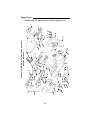
Parts List For RIDGID 16" Variable Speed Scroll Saw
Model No. SS16500
21
4
8
18
17 16 15
10
9
1
6
14
5
7
2
3
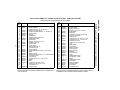
Repair Parts
RIDGID parts are available on-line at www.ridgidparts.com
Parts List for RIDGID 16" Variable Speed Scroll Saw Model No. SS16500
27
1
2
3
4
5
6
7
8
9
10
11
12
13
14
15
16
17
18
19
20
21
22
23
24
25
26
27
28
29
30
31
Part No.
Description
826177
Table
826257
Chute Sawdust
*
Screw Pan Hd Ty “T” 10-32 x 3/8
821532
Washer Curved Spring
821521
Screw Hex Wash Shldr Ty “T” 1/4-20 x 1/2
823808-1
Guide Drawer
826254
Drawer
826252
Knob Bevel
*
Washer 17/64 x 5/8 x 1/16
821510
Label Bevel Scale
826256
Scale Bevel
*
Washer 17/64 x 3/4 x 7/64
60326
Pin Roll .219 x 3/4
826298
Knob On/Off
826299
Guard Finger
*
Nut Hex Jam 3/8-32
*
Lockwasher 3/8
826201
Housing Motor
822016
Screw Hex Washer Hd Ty “T” #10 x 5/8
823634
• Motor
826867
Board, Control
823168
Screw Hex Washer Hd Ty “T” 10-32x3/8 Green
*
Lockwasher #10
823801-1
Cord w/Plug
809492
Screw Pan Hd Ty “T” 8-32 x 5/16
826057
Pointer
826136
Base
813094-1
Screw Hex Hd 10-32 x 7/8
*
Screw Hex Hd 1/4-20 x 1-1/2
*
Lockwasher 1/4
823830-1
Support Plate
* Standard hardware item - may be purchased locally
† These replacement parts are available where you purchased
your scroll saw.
Key
No.
32
33
34
35
36
37
38
39
40
41
42
43
44
45
46
47
48
49
50
51
52
53
54
55
56
57
58
59
60
61
62
Part No.
823827-1
823806
823800-1
*
823828
826255
*
826175
826198
66072
*
823802
*
826171
815200
821529
821530
826758
821531
823791-1
824646
823812
823810-1
*
*
823811-1
826278
821416
826199
826277
SP6141
Description
Spring Hold Down
Guard, Blade
Clamp Hold Down
Screw, Soc Set, 10-32 x 3/16
Support Bar
Plate Clip
Screw Soc Hd Cap 1/4-20 x 3/8
Support, Hold Down
Housing Left
Screw Pan Hd Ty “T” 8-32 x 1-3/8
Screw Pan Hd Ty “T” 8-32 x 1/2
Coupling Eccentric
Screw Soc Set 1/4-20 x 3/8
Link
Bearing Ball
Nut, Tension
Wedge, Tension
Knob, Tension
Spring Tension
Bellows
Cover Bellows
Hose
Holder Blade Lower
Pin Roll 3/16 x 9/16
† Blade
Holder Blade Upper
Arm Upper
Bearing Flanged
Housing Right
Arm Lower
Owner’s Manual
• Any attempt to repair this motor may create a hazard unless
repair is done by a qualified service technician. Repair service
is available at your nearest Authorized Service Center.
RIDGID parts are available on-line at www.ridgidparts.com
Key
No.
Repair Parts
Always Order By Part Number-Not By Key Number
Lifetime Warranty On RIDGID Tools
The RIDGID REPUTATION is the result of the
consistent product quality and years of pride in
workmanship. Rigorous checks and controls
from raw materials to packaged products insure
product confidence widely accepted as the
mark of the professional trades. Therefore,
RIDGID covers its products with a LIFETIME
WARRANTY against defects in material or
workmanship. To take advantage of this warranty, the complete product must be delivered
prepaid to any RIDGID AUTHORIZED SERVICE CENTER. Obviously, failures due to misuse, abuse or normal wear and tear are not
covered by this warranty. NO OTHER WARRANTY, WRITTEN OR ORAL, APPLIES. No
employee, agent, dealer or other person is
authorized to give any warranty on behalf of
RIDGID Power Tools, Emerson Electric Co.
Warranted products will be repaired or
replaced, at our option, at no charge to you and
returned to you via prepaid transportation. Such
replacement or repair is the exclusive remedy
available from RIDGID Power Tools, Emerson
Electric Co. Emerson Electric Co. is not liable
for damage of any sort, including incidental and
consequential damages. Some U.S.A. states
do not allow the exclusion or limitation of incidental or consequential damages, so the above
limitation or exclusion may not apply. This warranty gives you specific legal rights, and you
may have other rights which vary from state to
state.
QUESTIONS OR COMMENTS?
CALL 1-800-4-RIDGID
www.ridgidwoodworking.com
RIDGID Power Tools
Emerson Electric Co.
© 1998 Emerson Electric Co.
Part No. SP6141
Form No. SP6141-3
Printed in U.S.A. 7/99