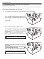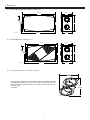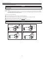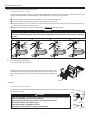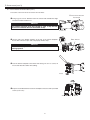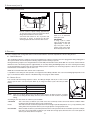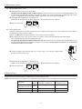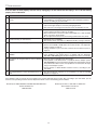
1
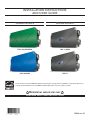
INSTALLATION INSTRUCTIONS AND USER GUIDE VENMAR BROAN MODELS VB0186 MODELS VB0068 EVO5 700 HRV HEPA VB0187 HRV 7.1 HEPA VB0067 EVO5 500 HRV HRV 5.1 * These products earned the ENERGY STAR® by meeting strict energy efficiency guidelines set by Natural Resources Canada and the US EPA. They meet ENERGY STAR requirements only when used in Canada. ! RESIDENTIAL INDOOR USE ONLY ! READ AND SAVE THESE INSTRUCTIONS 20846 rev. 03 ABOUT THIS GUIDE First, we want to congratulate you on your purchase of this excellent unit which will allow you and your family to enjoy clean and healthy air throughout your home for years to come! Since this publication covers several models, the illustrations are typical ones. Some details of your unit may be slightly different than the ones shown. Please take note that this manual uses the following symbols to emphasize particular information: ! WARNING Identifies an instruction which, if not followed, might cause serious personal injuries including possibility of death. CAUTION Identifies an instruction which, if not followed, may severely damage the unit and/or its components. NOTE: Indicates supplementary information needed to fully complete an instruction. ABOUT THESE UNITS LIMITATION For residential (domestic) installation only. Installation work and electrical wiring must be done by a qualified person(s) in accordance with all applicable codes and standards, including fire-rated construction codes and standards. ! WARNING TO REDUCE THE RISK OF FIRE, ELECTRIC SHOCK, OR INJURY TO PERSON(S) OBSERVE THE FOLLOWING: 1. Use this unit only in the manner intended by the manufacturer. If you have questions, contact the manufacturer at the address or telephone number listed in the warranty. 2. We recommend that your unit be inspected by a specialized technician once a year. 3. Before servicing or cleaning the unit, disconnect power cord from electrical outlet. 4. This unit is not designed to provide combustion and/or dilution air for fuel-burning appliances. 5. When cutting or drilling into wall or ceiling, do not damage electrical wiring and other hidden utilities. 6. Do not use the units with any solid-state speed control device other than the corresponding ones listed below: UNIT MAIN CONTROL AUXILIARY CONTROL EVO5 700 HRV HEPA AND EVO5 500 HRV 40405 40422 HRV 7.1 HEPA AND HRV 5.1 40410 40424 7. This unit must be grounded. The power supply cord has a 3-prong grounding plug for your personal safety. It must be plugged into a mating 3-prong grounding receptacle, grounded in accordance with the national electrical code and local codes and ordinances. Do not remove the ground prong. Do not use an extension cord. 8. Do not install in a cooking area or connect directly to any appliances. 9. Do not use to exhaust hazardous or explosive materials and vapors. 10. When performing installation, servicing or cleaning the unit, it is recommended to wear safety glasses and gloves. 11. Due to the weight of the unit, two installers are recommended to perform installation. 12. When applicable local regulations comprise more restrictive installation and/or certification requirements, the aforementioned requirements prevail on those of this document and the installer agrees to conform to these at his own expenses. CAUTION 1. 2. 3. 4. 5. To avoid prematurate clogged filters, turn OFF the unit during construction or renovation. Please read specification label on product for further information and requirements. Be sure to duct air outside – Do not intake/exhaust air into spaces within walls or ceiling or into attics, crawl spaces, or garage. Intended for residential installation only in accordance with the requirements of Part 9 of the National Building Code of Canada. Do not run any air ducts directly above or closer than 2 ft (0.61 m) to any furnace or its supply plenum, boiler, or other heat producing appliance. If a duct has to be connected to the furnace return plenum, it must be connected not closer than 9’ 10” (3 m) from this plenum connection to the furnace. 6. The ductwork is intended to be installed in compliance with all applicable codes. 7. When leaving the house for a long period of time (more than two weeks), a responsible person should regularly check if the unit operates adequately. 8. If the ductwork passes through an unconditioned space (e.g.: attic), the unit must operate continuously except when performing maintenance and/or repair. Also, the ambient temperature of the house should never drop below 18°C (65°F). 2 TABLE OF CONTENTS 1. TYPICAL INSTALLATIONS . . . . . . . . . . . . . . . . . . . . . . . . . . . . . . . . . . . . . . . . . . . . . . 4 1.1 FULLY DUCTED SYSTEM . . . . . . . . . . . . . . . . . . . . . . . . . . . . . . . . . . . . . . . . . . . . . . . . 4 1.2 CENTRAL DRAW POINT . . . . . . . . . . . . . . . . . . . . . . . . . . . . . . . . . . . . . . . . . . . . . . . . 4 1.3 SIMPLIFIED INSTALLATION . . . . . . . . . . . . . . . . . . . . . . . . . . . . . . . . . . . . . . . . . . . . . . . 4 2. DIMENSIONS . . . . . . . . . . . . . . . . . . . . . . . . . . . . . . . . . . . . . . . . . . . . . . . . . . 5 2.1 EVO5 700 HRV HEPA AND HRV 7.1 HEPA UNITS . . . . . . . . . . . . . . . . . . . . . . . . . . . . . . . . . 5 2.2 EVO5 500 HRV AND HRV 5.1 UNITS . . . . . . . . . . . . . . . . . . . . . . . . . . . . . . . . . . . . . . . . 5 2.3 JOIST OPENING REQUIRED FOR TANDEM® TRANSITION . . . . . . . . . . . . . . . . . . . . . . . . . . . . . . . . . . 5 3. INSTALLATION . . . . . . . . . . . . . . . . . . . . . . . . . . . . . . . . . . . . . . . . . . . . . . . . 6-13 3.1 INSPECT THE CONTENT OF THE BOX . . . . . . . . . 3.2 INSTALLATION KITS, TOOLS AND MATERIAL . . . . 3.3 LOCATING THE UNIT . . . . . . . . . . . . . . . . 3.4 PLANNING OF THE DUCTWORK . . . . . . . . . . 3.5 INSTALLING NON-INSULATED DUCTS AND DIFFUSERS . . . . . . . . . . . . . . . . . . . . . . . . . . . . . . . . . . . . . . . . . . . . . . . . . . . . . . . . . . . . . . . . . . . . . . . . . . . . . . . . . . . . . . . . . . . . . . . . . . . . . . . . . . . . . . . . . . . . . . . . . . . . . . . . . . . . . . . . . . . . . . . . . . . . . . . . . . . . . . . . . . . . . . .6 . .7 . .7 . .7 . 8-9 3.5.1 FULLY DUCTED SYSTEM . . . . . . . . . . . . . . . . . . . . . . . . . . . . . . . . . . . . . . . . . . . . . . . . . 8-9 3.5.2 CENTRAL DRAW POINT . . . . . . . . . . . . . . . . . . . . . . . . . . . . . . . . . . . . . . . . . . . . . . . . . . 9 3.5.3 SIMPLIFIED INSTALLATION . . . . . . . . . . . . . . . . . . . . . . . . . . . . . . . . . . . . . . . . . . . . . . . . . . 9 3.6 INSTALLING INSULATED FLEXIBLE DUCTS . . . . . . . . . . . . . . . . . . . . . . . . . . . . . . . . . . . . . . 10-11 3.6.1 CONNECTION TO TANDEM TRANSITION . . . . . . . . . . . . . . . . . . . . . . . . . . . . . . . . . . . . . . . . . . . .10 3.6.2 CONNECTION TO THE UNIT PORTS . . . . . . . . . . . . . . . . . . . . . . . . . . . . . . . . . . . . . . . . . . . . .11 3.7 INSTALLING DUAL EXTERIOR HOOD . . . . . . . . . . . . . . . . . . . . . . . . . . . . . . . . . . . . . . . . . 11-12 3.7.1 ASSEMBLING DUAL EXTERIOR HOOD . . . . . . . . . . . . . . . . . . . . . . . . . . . . . . . . . . . . . . . . . . . .11 3.7.2 LOCATING DUAL EXTERIOR HOOD . . . . . . . . . . . . . . . . . . . . . . . . . . . . . . . . . . . . . . . . . . . . . .11 3.7.3 CONNECTING TANDEM TRANSITION TO DUAL EXTERIOR HOOD . . . . . . . . . . . . . . . . . . . . . . . . . . . . . . . . .12 3.8 CONNECTING THE DRAIN . . . . . . . . . . . . . . . . . . . . . . . . . . . . . . . . . . . . . . . . . . . . . . 13 4. CONTROLS . . . . . . . . . . . . . . . . . . . . . . . . . . . . . . . . . . . . . . . . . . . . . . . . . 13-19 4.1 BOOTING SEQUENCE . . . . . . . . . . . . 4.2 DEFROST CYCLES . . . . . . . . . . . . . 4.3 MAIN WALL CONTROL INSTALLATION . . . . . 4.4 WALL CONTROL(S) CONNECTION TO THE UNIT 4.5 MAIN WALL CONTROL DESCRIPTION . . . . . 4.6 MAIN WALL CONTROL USE . . . . . . . . . . . . . . . . . . . . . . . . . . . . . . . . . . . . . . . . . . . . . . . . . . . . . . . . . . . . . . . . . . . . . . . . . . . . . . . . . . . . . . . . . . . . . . . . . . . . . . . . . . . . . . . . . . . . . . . . . . . . . . . . . . . . . . . . . . . . . . . . . . . . . . . . . . . . . . . . . . . . . . . . . . . . . . . . . . . . . . . . . . . . . 4.6.1 OPERATION MODES . . . . . . . . . . . . . . . . . . . . . . . . . . . . . . . . . . . . . . . . . . 4.6.2 TURBO FUNCTION PUSH BUTTON . . . . . . . . . . . . . . . . . . . . . . . . . . . . . . . . . . . 4.6.3 CHANGING RECIRCULATION TO OFF FOR AUTO AND ECO MODES . . . . . . . . . . . . . . . . . 4.6.4 SETTING THE DISPLAYED TEMPERATURE UNIT . . . . . . . . . . . . . . . . . . . . . . . . . . . . . . 4.6.5 UNIT MAINTENANCE INDICATOR . . . . . . . . . . . . . . . . . . . . . . . . . . . . . . . . . . . . . 4.6.6 HOW TO CHANGE MINIMUM AND MAXIMUM AIR EXCHANGE TEMPERATURE LIMITS FOR ECO AND AUTO MODES . . . . . . . . . . . . . . . . . . . . . . . . . . . . . . . . . . . . . . . . . . . . . . . . . . . . . . . . . . . . . . 13 . . 13 .14-15 . . 15 . . 16 .16-19 . . . . . . . 16-17 . . .17 . . .18 . . .18 . . .17 . . .19 5. MAINTENANCE . . . . . . . . . . . . . . . . . . . . . . . . . . . . . . . . . . . . . . . . . . . . . . . . 20-22 5.1 MAINTENANCE CYCLES . . . . . . . . . . . . . . . . . . . . . . . . . . . . . . . . . . . . . . . . . . . . . . . 20 5.2 REGULAR MAINTENANCE . . . . . . . . . . . . . . . . . . . . . . . . . . . . . . . . . . . . . . . . . . . . . 21-22 5.3 ANNUAL MAINTENANCE . . . . . . . . . . . . . . . . . . . . . . . . . . . . . . . . . . . . . . . . . . . . . . . 22 6. SERVICE PARTS . . . . . . . . . . . . . . . . . . . . . . . . . . . . . . . . . . . . . . . . . . . . . . . . 22 7. TROUBLESHOOTING . . . . . . . . . . . . . . . . . . . . . . . . . . . . . . . . . . . . . . . . . . . . . . 23 8. WARRANTY . . . . . . . . . . . . . . . . . . . . . . . . . . . . . . . . . . . . . . . . . . . . . . . . . . 24 3 1. TYPICAL INSTALLATIONS Use the following illustrations as guidelines to help you decide on how the unit will be installed. All the units should be hung from the joists. In every case, bathroom fans and a range hood could be used to exhaust stale air. However, please note that an optional bathroom installation kit (no. IKBV1000 for Venmar units and no. IKBB1000 for Broan units) is available for house where there is no bathroom fans. Also, for homes with more than one level, we recommend one exhaust register at the highest level. There are 3 installation methods: Fully Ducted System, Central Draw Point and Simplified Installation. NOTE: An electrical outlet has to be available within 3 feet of the unit. 1.1 FULLY DUCTED SYSTEM (PRIMARILY FOR HOMES WITH RADIANT HOT WATER OR ELECTRIC BASEBOARD HEATING) Stale air coming from the register located at the highest level of the house is exhausted to the outside. Fresh air from outside is filtered and supplied by the register located in the lowest liveable level. Homes with more than one level require at least one exhaust register at the highest level. See figure at right. VH0088 1.2 CENTRAL DRAW POINT (CONNECTION TO A FORCED AIR SYSTEM) Stale air coming from the register located at the highest level of the house is exhausted to the outside. Fresh air from outside is filtered and supplied to the return (plenum) or the supply duct of the forced air unit. See figure at right. For this type of installation, it is not essential that the forced air system blower runs when the unit is in operation, but we recommend it. NOTE: Home with multiple forced air systems should have one unit on each system. CAUTION Do not connect the unit to any forced air system supply duct. VH0089 1.3 SIMPLIFIED INSTALLATION (CONNECTION TO A FORCED AIR SYSTEM) Stale air is exhausted to the outside. Fresh air from outside is filtered and supplied to the return (plenum) or the supply duct of the forced air unit. See figure at right. To avoid cross-contamination and achieve the highest efficiencies, the forced air system blower must always be ON. NOTE: Home with multiple forced air systems should have one unit on each system. CAUTION Do not connect the unit to any forced air system supply duct. VH0090 4 2. DIMENSIONS 2.1 EVO5 700 HRV HEPA AND HRV 7.1 HEPA UNITS 37 7/8” 12½” 17 7/16” 39 3/8” VK0082A 11¼” 2.2 EVO5 500 HRV AND HRV 5.1 UNITS 35 7/8” 12½” 17 7/16” VK0083A 37 7/16” 11¼” 2.3 JOIST OPENING REQUIRED FOR TANDEM® TRANSITION 9¾” 248 mm The joist opening needed to install the Tandem tansition* (included in ISKV1000 and ISKB1000 installation kits) must be 9¾” (248 mm) minimum. Also, the maximum height of the Tandem transition is 8¾” (222 mm). See Tandem transition end view at right. * Patended 8¾” 222 mm VD0118A 5 3. INSTALLATION 3.1 INSPECT THE CONTENT OF THE BOX NOTE: Before proceeding to the installation, check the content of the box. If items are missing or damaged, contact the manufacturer. Remove all packaging material from the unit. • Inspect the exterior of the unit for shipping damage. Ensure that there is no damage to the door, door latches, ports, power cord, etc. • Remove the transport bracket screws (A) located on the bottom of the unit. A VD0313 • Unlatch, open (B) and remove (C) the unit door. CAUTION In order to prevent damages to the door hooks, do not open completely the unit door; tilt it about 3” from the unit base and lift it up. See illustration at right. • Remove the transport tape over the heat recovery core of the unit. C ±3” B VD0304A D • Remove the last retaining screws (D) of the transport brackets and discard. VD0314 • Inspect the inside of the unit for damage. Ensure that blower assembly, heat recovery core, core filters, insulation, dampers, prefilter and HEPA filter (EVO5 700 HRV HEPA and HRV 7.1 HEPA units only), etc. are all intact, then reinstall the door. P TO S SU DES l. : sta d’in e: dat te Da tal. Ins T ON FR NT A AV __ /_ _/ __ __ NOTE: On EVO5 700 HRV HEPA and HRV 7.1 HEPA units only, write the installation date on the HEPA filter frame for future reference (see illustration at right). 212 93 da . stal ’in te: ed Dat al. Inst T ON FR NT A AV : __ _/ /_ __ __ VD0309 6 3. INSTALLATION 3.2 INSTALLATION KITS, TOOLS AND MATERIAL The installation kit needed to perform most installations is IKSV1000 for Venmar units and IKSB1000 for Broan units. Following are the tools and material needed: • • • • • • • • • • • Measuring tape Phillips no. 2 or Robertson no. 2 screwdriver Small flat blade screwdriver (for wall control connection) Wire stripper (for wall control connection) Hammer and flat blade screwdriver (for plenum connection installation only, to make holes in existing metal duct) Scissors or utility knife (to cut duct tape) Duct tape Tin snips or metal shear (for plenum connection installation only, to cut ductwork) Aluminum duct tape (for plenum connection installation only) Jig saw Caulking gun and caulking. 3.3 LOCATING THE UNIT Choose an appropriate location for the unit. • • • • • • • Within an area of the house where the ambient temperature is kept between 10°C (50°F) and 40°C (104°F) Away from living areas (dining room, living room, bedroom), if possible So as to provide easy access to the interior of the unit, for regular and annual maintenance Close to an exterior wall, so as to limit the length of the insulated flexible duct to and from the unit Away from hot chimneys and other fire hazards Allow for a power source (standard 3-prong grounding outlet) Close to a drain. If no drain is close by, use a pail to collect run-off. Hang the unit with the four hooks, chains and springs provided. See illustration at right. CAUTION Make sure the unit is level. VD0306 3.4 PLANNING OF THE DUCTWORK • • • • Keep it simple. Plan for a minimum of bends and joints. Keep the length of insulated ducts to a minimum. Do not ventilate crawl spaces or cold rooms. Do not attempt to recover the exhaust air from a dryer or a range hood. This would cause clogging of the filters and recovery module. If the house has two floors or more, be sure to plan for at least one exhaust register on the highest lived-in level. 7 3. INSTALLATION (CONT’D) 3.5 INSTALLING NON-INSULATED DUCTS AND DIFFUSERS 3.5.1 FULLY DUCTED SYSTEM (AS ILLUSTRATED IN SECTION 1.1) ! WARNING Never install a stale air exhaust diffuser in a closed room where a combustion device operates, such as a gas furnace, a gas water heater or a fireplace. Stale air exhaust ductwork • Install the stale air exhaust diffuser in the main area where the contaminants are produced: kitchen, living room, etc. Position the diffuser as far from the stairway as possible and in such a way that the air circulates in all the lived-in spaces in the house. If desired, you can install another diffuser (sold separately). • If a diffuser is installed in the kitchen, it must be located at least 4 feet (1.2 m) from the range. • Install the diffuser 6 to 12 inches (152 to 305 mm) from the ceiling on an interior wall OR install it in the ceiling. Fresh air distribution ductwork • Install the fresh air distribution diffuser in a large, open area in the lowest level to ensure the greatest possible air circulation. • Keep in mind that the fresh air diffuser must be located as far as possible from the stale air diffuser. If desired, you can install another diffuser (sold separately). • Install the diffuser either in the ceiling OR 6 to 12 inches (152 to 305 mm) from the ceiling on an interior wall. (The cooler air will then cross the upper part of the room and mix with room air, before descending to occupant’s level.) • If a register must be floor installed, direct the airflow up the wall. HOW TO CONNECT THE FLEXIBLE DUCTS TO THE DIFFUSERS Ø 5¼” Once the diffusers location is determined, cut out 5¼” diameter hole. Run one end of the flexible duct through the hole and fix it to the diffuser base (1), using a tie wrap and duct tape. Assemble the diffuser base to the wall (or ceiling using its 4 no. 8 x 3/4” screws. Then, slide in the diffuser (2). See illustration at right. 1 2 VJ0094A UNIT PORTS IDENTIFICATION Each unit port has an identification label beside it to avoid wrong duct connections to the unit. Always refer to these labels before performing any duct and port connection. UNIT DOOR VJ0096 8 3. INSTALLATION (CONT’D) 3.5 INSTALLING NON-INSULATED DUCTS AND DIFFUSERS (CONT’D) 3.5.1 FULLY DUCTED SYSTEM (AS ILLUSTRATED IN SECTION 1.1) (CONT’D) HOW TO CONNECT THE FLEXIBLE DUCTS TO THE UNIT PORTS RIGHT SIDE OF THE UNIT Both flexible ducts attached to the diffusers must be connected to the bottom ports of the unit. When facing the unit door, the fresh air to building port is located on left side and the exhaust air from building port is on the right side. Refer to the identification labels affixed beside each unit ports. Using tie wrap, attach the fresh air to building duct to its corresponding port, then do the same for the exhaust air to building duct and port. See illustration at right. NOTE: Use an insulated duct (not included) if the duct will have to go through a space where it is possible to experience extreme temperature conditions (eg: in northern area, not unheated attic in winter or uncooled attic in southern area). Also, if you plan to stop the unit for more than 12 hours, we recommend to cover the duct with R12 insulation. VJ0098 3.5.2 CENTRAL DRAW POINT (AS ILLUSTRATED IN SECTION 1.2) Stale air exhaust ductwork Same as for Fully Ducted System, described in step 3.5.1. Fresh air distribution ductwork ! WARNING When performing duct connections, always use approved tools and materials. Respect all corresponding laws and safety regulations. Please refer to your local building code. • • • Locate the opening for fresh air ductwork on the forced air unit return duct at a minimum linear distance of 9’ 10” (3 m) upstream (from forced air unit drop: A+B+C). Cut out a 5” Ø hole in this location, using metal shear. Use a metal transition (not included, available in hardware store) to connect the unit duct to the forced air unit return duct. Attach the other end of the flexible duct to the fresh air to building port (see icon on the left side of the unit). Use tie wrap and duct tape to seal the connection. See illustration at right. UNIT DOOR METAL TRANSITION VJ0099 A + B + C = NOT LESS THAN 9’ 10” (3 M) 3.5.3 SIMPLIFIED INSTALLATION (AS ILLUSTRATED IN SECTION 1.3) Fresh air distribution ductwork (return side connection) Same as for Central Draw Point, described in step 3.5.2. Stale air exhaust ductwork (return side connection) ! WARNING When performing duct connections, always use approved tools and materials. Respect all corresponding laws and safety regulations. Please refer to your local building code. • • • Locate the opening for stale air ductwork on the forced air unit return duct at least 3’ (0.9 m) from fresh air ductwork connection. Cut out a 5” Ø hole in this location, using metal shear. Use a metal transition (not included, available in hardware store) to connect the unit duct to the forced air unit return duct. Attach the other end of the flexible duct to the exhaust air from building port (see icon on the right side of the unit). Use tie wrap and duct tape to seal the connection. See illustration at right. UNIT DOOR 3’ (0.9 M) MINIMUM VJ0100 CAUTION The furnace blower must be running when the ventilation unit is in operation. 9 METAL TRANSITIONS A + B + C = NOT LESS THAN 9’ 10” (3 M) 3. INSTALLATION (CONT’D) 3.6 INSTALLING INSULATED FLEXIBLE DUCTS CAUTION Make sure the vapor barrier on the insulated ducts does not tear during installation to avoid condensation within the ducts. Use the following procedure for connecting the insulated flexible ducts to the Tandem® transition (exhaust air to outside and fresh air from outside). NOTE: If the joists are perpendicular to the ducts, or if the connection to the exterior hood is in a limited area, the installation will need two exterior hoods instead of one. In this case, do not use the Tandem transition; go to point 3.6.2 and refer to the optional single hood enclosed instructions. 3.6.1 CONNECTION TO TANDEM TRANSITION For each duct, pull back the insulation to expose the interior flexible duct. Connect the interior flexible duct to the smaller part of the Tandem transition (5’’ oval) using a tie wrap. Pull the insulation over the joint. Pull the vapor barrier over the insulation. Apply duct tape gently to the joint in order to make an airtight seal. See figures below. CAUTION The exhaust air to outside duct MUST BE connected to the TOP of Tandem transition. EXHAUST AIR TO OUTSIDE DUCT ON TOP VJ0022 VJ0025 VJ0023 VJ0024 10 3. INSTALLATION (CONT’D) 3.6 INSTALLING INSULATED FLEXIBLE DUCTS (CONT’D) 3.6.2 CONNECTION TO THE UNIT PORTS Use the following procedure for connecting the insulated flexible ducts to the unit ports (exhaust air to outside and fresh air from outside). Refer to identification labels beside ports before performing any duct and port connection. For both remaining ducts, pull back the insulation to expose the interior flexible duct. Connect the interior flexible duct to the inner ring of the port using a tie wrap. Pull the insulation over the joint and tuck it between the inner and outer rings of the port. Pull the vapor barrier over the insulation and over the outer ring of the port. Apply duct tape carefully to the joint in order to make an airtight seal. See figures below. CAUTION Avoid compressing the insulation when you pull the tape tightly around the joint. Compressed insulation loses its insulation properties and causes water dripping due to condensation on the exterior surface of the duct. VJ0101 3.7 INSTALLING DUAL EXTERIOR HOOD* 3.7.1 ASSEMBLING DUAL EXTERIOR HOOD Exterior dual hood is sent in separate parts. Using included 2 no. 8 x 3/4” screws, assemble the top metal screen and the plastic grille to the dual exterior hood. Then, slide the bottom metal screen to the dual exterior hood. See illustration at right. VO0024 * Patended 3.7.2 LOCATING DUAL EXTERIOR HOOD The dual exterior hood must be installed at a minimum distance of 18 inches (457 mm) from the ground. See illustration at right. ! WARNING Make sure this hood is at least 6 feet (1.8 m) away (or more, as per applicable building codes or standards) from any of the following: • Dryer exhaust, high efficiency furnace vent, central vacuum vent • Gas meter exhaust, gas barbecue-grill • Any exhaust from a combustion source • Garbage bin and any other source of contamination 18” (457 mm) VD0083A 11 3. INSTALLATION (CONT’D) 3.7 INSTALLING DUAL EXTERIOR HOOD (CONT’D) 3.7.3 CONNECTING TANDEM TRANSITION TO DUAL EXTERIOR HOOD EXHAUST AIR TO OUTSIDE DUCT ON TOP Using a jig saw, cut a 6” diameter hole in the exterior wall and slide the single end of the Tandem transition in it. CAUTION The Tandem transition must be inserted in such a way that the exhaust air to outside duct will be located on top. VD0084 Join the end of the Tandem transition to the rear of the exterior backplate. Secure with 2 Xmas tree pins and seal properly with duct tape. XMAS TREE PIN CAUTION The exterior backplate must be installed with the word “TOP’’ pointing upward. VD0085 Lean the exterior backplate to the exterior wall. Using 4 no. 8 x 1½” screws, fix it to the wall. Seal the outline with caulking. VD0086 Snap the assembled exterior hood on its backplate and secure with 2 provided screws (no. 8 x 3/4”). VD0087 12 SCREW 3. INSTALLATION (CONT’D) 3.8 CONNECTING THE DRAIN TIE WRAP ± 12” ± 12” ± 1” VD0307A Cut two sections of plastic tubing, approximately 12” long, and connect each one to both inner drain fittings located under the unit as shown. Join these both sections to the “T” junction and main tube as shown, to prevent the unit from drawing unpleasant odors from the drain source. VD0308A Run the tube to the floor drain or to an alternative drain pipe or pail. IMPORTANT If using a pail to collect water, locate the tube end approximately 1” from the top of the pail in order to prevent water from being drawn back up into the unit. 4. CONTROLS This unit is equipped with an integrated defrost control located under the electrical compartment of the unit. Plug the unit. 4.1 BOOTING SEQUENCE The unit booting sequence is similar to a personnal computer boot sequence. Each time the unit is plugged after being unplugged, or after a power failure, the unit will perform a booting sequence before starting to operate. During the booting sequence, the integrated defrost control LED (2 in illustration below) will be OFF for 3 seconds, and then will turn RED for the rest of the booting sequence (approximately 15 seconds). During this RED light phase, the unit is checking and resetting the motorized damper position. Once the motorized damper position completely set, the booting sequence is done; the color of the LED will show on which defrost cycle the unit is set. NOTE: No command will be taken until the unit is fully booted. If a problem occurs during the unit operation, its integrated control LED (2) will blink. The color of the blinking light depends on the type of error detected. Refer to Section 7 Troubleshooting on last page for further details. 4.2 DEFROST CYCLES Five seconds after the booting sequence is done, the LED (2) will light and stay lit to show in which defrost cycle the unit is set. Use the push button (1) to change the defrost cycle of the unit (see table below). LED COLOR DEFROST CYCLE GREEN STANDARD RED PLUS AMBER DISCRETION 1 NOTE: There is a 15-minute delay for the new defrost cycle choice to be kept in memory; if a power 2 failure occurs during this time delay, when the power returns, the unit resume to its previous VD0310 setting. According to your need, there are 3 defrost cycles available: STANDARD: This is the factory set defrost cycle, which is the most commonly used to suit normal weather conditions. When needed, the unit will perform defrost cycle on high speed. PLUS: This mode has been created for people who live in cold region (outside temperature -27°C [-17°F] and lower). This setting makes the unit perform defrost cycle on high speed for a longer period of time. DISCRETION: When needed, the defrost cycle will be performed on the same speed than the unit ventilation speed. For example, if the unit is set on high speed, the defrost cycle will be done on high speed, but if the unit is set on low speed, the defrost cycle will be done on low speed. 13 4. CONTROLS (CONT’D) 4.3 MAIN WALL CONTROL INSTALLATION These units should be controlled using a main wall control (included). NOTE: If an optional auxiliary control is used, if activated, this auxiliary control will override the main control operation. ! WARNING Always disconnect the unit before making any connections. Failure in disconnecting power could result in electric shock or damage of the wall control or electronic module inside the unit. CAUTION Failure to comply with the following can cause erratic operation of the unit and/or the wall control: • Never install more than one main wall control per ventilation unit; • Keep control low voltage wiring at least 1 foot (305 mm) away from motors, lighting ballast, light dimming circuit and power distribution panel. Do not route control wiring alongside house power wiring; • Ensure the wires are securely connected. Route the control cable (included) from the unit to a convenient location for the wall control. Loosen the locking screw (the screw should not be removed). VC0128 Detach the faceplate from the mounting plate by pulling the bottom part. If necessary, bore the mounting holes and insert anchors. VC0129 Run the cable (4 wires) through the opening of the mounting plate and mount the plate to the wall using 2 screws (included in the unit parts bag). VC0130 14 4. CONTROLS (CONT’D) 4.3 MAIN WALL CONTROL INSTALLATION (CONT’D) Splice back the end of the cable to access the 4 wires. Strip the end of each wire. Connect each wire to its corresponding terminal: YELLOW wire to “Y’’, RED wire to “R’’, GREEN wire to “G’’ and BLACK wire to “B’’. See illustration at right. GREEN wire RED wire YELLOW wire BLACK wire Y RG B VE0271A Reinstall the front module onto the back plate and tighten the locking screw. 4.4 WALL CONTROL(S) CONNECTION TO THE UNIT B A Use the terminal connector included in the installation kit to perform the electrical connection for main and optional wall controls. Check if all wires are correctly inserted in their corresponding holes in the terminal block. (A wire is correctly inserted when its orange receptacle is lower than another one without wire. On illustration at right, wire A is correctly inserted, but not wire B.) Splice back the end of the cable to access the 4 wires. Strip the end of each wire. Connect each wire to its corresponding terminal: YELLOW wire to “Y’’, RED wire to “R’’, GREEN wire to “G’’ and BLACK wire to “B’’. Check if all wires are correctly inserted in their corresponding holes in the terminal block. Connect the auxiliary control cable, if installed (not shown). VE0272 Once the control(s) connections have been made, insert the terminal connector in the electrical compartment interface. Plug the unit. VE0273 15 4. CONTROLS (CONT’D) 4.5 MAIN WALL CONTROL DESCRIPTION The included wall control is 40405 (intented for EVO5 500 HRV and EVO5 700 HRV HEPA Venmar units only) or 40410 (intented for HRV 5.1 and HRV 7.1 HEPA Broan units only). The wall control is in OFF mode when power is applied for the first time. After a power failure, the wall control returns to its original operation mode. ON/OFF key. When wall control is OFF, the unit is on stand-by mode, so it will only respond to override wall control (if present). Only the house icon appears on LCD screen. When wall control is ON, the house icon is still there, and the label mode in which the unit operates appears at the bottom of LCD screen. See operation modes for more details. LCD screen. Backlight: If the backlight is not illuminated, the first key pressed (no matter which key) shall turn on the backlight. The backlight remains illuminated for 10 seconds after the last key is pressed. MODE key ECO mode key TURBO function key VC0131 4.6 MAIN WALL CONTROL USE 4.6.1 OPERATION MODES When the wall control is ON, press the MODE key to choose the operation mode of the ventilation unit. Operating Mode label will then appear on LCD screen (AUTO, ECO, CONT and RECIRC). AUTO MODE The ventilation unit exchanges air intermittently on a one-hour cycle as follows: exchanges air during 20 minutes on low speed and then recirculation on high speed for 40 minutes (or OFF for 40 minutes, see section 4.6.3). Repeat cycle after the 40-minute period. NOTE: The outdoor temperature value displayed during AUTO recirculation or AUTO off cycle period comes from the reading while the unit is performing air exchange (first part of AUTO mode cycle). Also, keep in mind that outdoor temperature reading is taken from the unit fresh air from outside port; due to the lenght of the insulated duct, the result of the reading is slightly different from the real outside temperature. FIRST PART OF THE CYCLE LAST PART OF THE CYCLE OR 20 minutes of air exchange in low speed 40 minutes of recirculation on high speed 16 40 minutes OFF in AUTO mode 4. CONTROLS (CONT’D) 4.6 MAIN WALL CONTROL USE (CONT’D) 4.6.1 OPERATION MODES (CONT’D) ECO MODE The ventilation unit exchanges air intermittently on a one-hour cycle as follows: a 10-minute cycle of air exchange, then 50 minutes on recirculation on low speed (or OFF for 50 minutes, see section 4.6.3). Return to air exchange after the 50-minute period. NOTE: The outdoor temperature value displayed during ECO recirculation or ECO off cycle comes from the reading while the unit is performing air exchange (first part of ECO mode cycle). Also, keep in mind that outdoor temperature reading is taken from the unit fresh air from outside port; due to the lenght of the insulated duct, the result of the reading is slightly different from the real outside temperature. ECO MODE KEY When the wall control is ON, press the ECO key to access directly to ECO mode, without scrolling all other modes on the screen. Press another time to exit the ECO mode and return to the previous operation mode. LAST PART OF THE CYCLE FIRST PART OF THE CYCLE OR 10 minutes of air exchange on low speed 50 minutes of recirculation on low speed CONT MODE 50 minutes OFF in ECO mode RECIRC MODE Continuous air exchange on low speed Continuous recirculation on high speed NOTE: In this mode, there is no outside temperature displayed. When the wall control is ON (no matter the operation mode), pressing on TURBO key will turn the unit on air exchange in high speed during 4 hours, then, the unit will get back to its previous operation mode*. When activated, the tornado icon is flashing. To exit this function before the end of its 4-hour cycle, press another time on TURBO key; the unit will get back to its previous operation mode*. *Except if it was in ECO mode, for this particular case, the unit will get back to the mode chosen before ECO mode. 17 more than When the wall control is ON (no matter 4 sec. the operation mode), pressing on TURBO key for more than 4 seconds will turn the unit on air exchange in high speed with no time limit. 4.6.2 TURBO FUNCTION KEY When activated, the tornado icon appears on screen. To exit this function, press another time on TURBO key; the unit will get back to its previous operation mode*. *Except if it was in ECO mode, for this particular case, the unit will get back to the mode chosen before ECO mode. 4. CONTROLS (CONT’D) 4.6 MAIN WALL CONTROL USE (CONT’D) 4.6.3 CHANGING RECIRCULATION TO OFF FOR AUTO AND ECO MODES NOTE: Prior to perform this setting, Press and hold simultaneously the wall control must be ON. MODE and ECO keys during 4 seconds to access setting. Letters rEC and circled arrows are flashing (default configuration setting). 4 sec. Press on MODE key to change for OFF. The word OFF is flashing to show setting has been changed to OFF. Press and hold simultaneously MODE and ECO keys during 4 seconds to save and exit setting. 4 sec. NOTE: To get back to RECIRCULATION in AUTO and ECO modes (in second part of cycle), repeat the complete procedure. 4.6.4 SETTING THE DISPLAYED TEMPERATURE UNIT The temperature unit displayed is factory set in Celcius (°C), but if desired, it can be changed to Fahrenheit (°F). Follow these steps: NOTE: Prior to perform this setting, the wall control must be ON. Press and hold on ECO key during 4 seconds. °F will flash on screen one moment to show it is now the current temperature unit, then will stay on screen. 4 sec. NOTE: To get back to °C for temperature display, repeat the complete procedure. 4.6.5 UNIT MAINTENANCE INDICATOR Once the maintenance has been done, reset the wall control by pressing simultaneously on ECO and TURBO keys. The wrench icon will disappear from screen. 18 When it is time to perform maintenance on the unit, a wrench icon appears on screen, no matter the mode the unit is in. Go to section 5. Maintenance. NOTE: This icon disappears when turning OFF the wall control, but reappears when turning it back ON. 4. CONTROLS (CONT’D) 4.6 MAIN WALL CONTROL USE (CONT’D) 4.6.6 HOW TO CHANGE MINIMUM AND MAXIMUM AIR EXCHANGE TEMPERATURE LIMITS FOR ECO AND AUTO MODES The minimum and maximum temperature limits for air exchange allow to stop air exchange with the outside for better comfort in the house. Factory set values are: minimum -25°C (-13°F), maximum 27°C (82°F). If desired, these values can be changed by following this procedure: NOTE: Prior to perform this setting, the wall control must be ON. 4 sec. Press and hold simultaneously MODE and TURBO keys during 4 seconds to access lower value setting. OR (according to the displayed temperature unit chosen) Air exchange arrows and °C ext. (°F ext.) appear on screen while -25 (-13) will flash (factory set value). OR OR NOTE: To access directly to set higher value without changing lower value, press on MODE key. To enter a lower value, press on ECO key; to enter a higher value, press the TURBO key. Press and hold simultaneously MODE and TURBO keys during 4 seconds to confirm and quit this setting. Press on MODE key to access higher value setting. OR (according to the displayed temperature unit chosen) OR Air exchange arrows and °C ext. (°F ext.) appear on screen while 27 (82) flashes (factory set value). OR 4 sec. Use ECO or TURBO keys until the desired value appears on screen. To enter a lower value, press on ECO key; to enter a higher value, press the TURBO key. Use ECO or TURBO keys until the desired value appears on screen. 19 5. MAINTENANCE ! WARNING Risk of electric shock. Before performing any maintenance, always turn off and disconnect the unit from its power source. Refer to the illustration at right to identify the inner removable parts of your unit: A. Heat recovery core B. Heat recovery core filters (2) C. Prefilter (EVO5 700 HRV HEPA and HRV 7.1 HEPA units only) D. HEPA filter (EVO5 700 HRV HEPA and HRV 7.1 HEPA units only) E. Core bracket (EVO5 700 HRV HEPA and HRV 7.1 HEPA units only) E A B D C B VL0058 5.1 MAINTENANCE CYCLES These units need regular and annual maintenances. When the wrench icon appears on wall control screen, perform the required maintenance, according to the unit model. MAINTENANCE TABLE FOR EVO5 700 HRV HEPA AND HRV 7.1 UNITS MAINTENANCE TABLE FOR EVO5 500 HRV AND HRV 5.1 UNITS APPEARANCE MAINTENANCE TYPE APPEARANCE MAINTENANCE TYPE FIRST TIME REGULAR FIRST TIME REGULAR SECOND TIME REGULAR SECOND TIME REGULAR + PREFILTER REPLACEMENT THIRD TIME REGULAR THIRD TIME REGULAR FOURTH TIME ANNUAL FOURTH TIME ANNUAL + PREFILTER HEPA FILTER REPLACEMENT AND As shown on both tables above, the annual maintenance ends the maintenance cycle. After an annual maintenance, the next time the wrench icon will appear on wall control screen, a new maintenance cycle will start. 20 5. MAINTENANCE (CONT’D) 5.2 REGULAR MAINTENANCE Perform this maintenance on the unit every time the wrench icon appears on wall control screen. Turn the unit OFF and unplug it. VD0005 Unlatch and tilt the door (A) from the unit base, then lift it up (B) and set aside. CAUTION In order to prevent damages to the door hooks, do not open completely the unit door; tilt it about 3” from the unit base and lift it up. See illustration at right. B ±3” VD0304A A CORE BRACKET Slide out the heat recovery core, the core bracket and all the filters. NOTE: Core bracket, HEPA filter and prefilter only in HRV 7.1 HEPA and EVO5 700 HRV HEPA units. HEPA FILTER PREFILTER HEAT RECOVERY CORE CORE FILTERS VL0057 Clean the inside wall of the unit with a damp cloth, then wipe with a dry one. Remove dust on core using a vacuum cleaner with a soft brush attachment. Wash both core filters under hot water with mild soap. Rinse thoroughly and let dry completely. 21 5. MAINTENANCE (CONT’D) 5.2 REGULAR MAINTENANCE (CONT’D) Reinstall the heat recovery core with its filters. For EVO5 700 HRV HEPA and HRV 7.1 HEPA units only: The heat recovery core must be reinstalled BEFORE the core bracket. Reinstall the HEPA filter but before reinstalling the prefilter, look at the installation date on HEPA filter frame. If there are more than 6 months passed, discard the prefilter and install a new one, but keep the HEPA filter. Reinstall the door, plug back the unit and turn it on. NOTE: The unit will return to its previous setting after a 20-second delay for boot sequence. Reset the wall control. VQ0083 5.3 ANNUAL MAINTENANCE Perform this maintenance on the unit when the wrench icon appears on wall control screen for the fourth time (refer to tables in 5.1 Maintenance Cycles on previous page). Perform steps to of the regular maintenance then continue with the followings: Allow the heat recovery core to soak for 3 hours in a solution of warm water and mild soap (dishwashing liquid). Rinse carefully, drain off water and reinstall with its filters. For EVO5 700 HRV HEPA and HRV 7.1 HEPA units only: The heat recovery core must be reinstalled BEFORE the core bracket. Discard HEPA filter and its prefilter and replace with new ones. DO NOT FORGET TO WRITE THE INSTALLATION DATE ON NEW HEPA FILTER FRAME. Check the exterior hood; make sure there are no leaves, twigs, ice or snow that could be drawn into the vent. Clean if necessary. VD0312 Reinstall the door, plug back the unit and turn it on. NOTE: The unit will return to its previous setting after a 20-second delay for boot sequence. Reset the wall control. VQ0083 6. SERVICE PARTS All parts listed in the following table are available where you have bought your unit. NOTE: Please note that parts not listed are not available; those parts require assembly knowledge that only manufacturer can garantee. Part Number Qty. in EVO5 700 HRV HEPA and HRV 7.1 HEPA units Qty. in EVO5 500 HRV and HRV 5.1 units 21293 1 - Prefilter (2 per kit) 61561 1 - Core filter 61563 2 2 Description HEPA filter (1 per kit) and prefilter (2 per kit) kit 22 7. TROUBLESHOOTING If the unit does not work properly, reset the unit by unplugging it for one minute and then replug it. If it is still not working properly, refer to table below. Problems You should try this 1 The error code E1 or E3 appears on wall control screen. • Reset the unit by unplugging it for 30 seconds. • If the problem is not solved, contact Venmar or Broan-NuTone customer service, according to your unit model. 2 Unit does not work. • See if the unit is plugged in. • Check if the upper left port is free from packaging material. • See if the unit is receiving power from the house circuit breaker or fuse. 3 Condensation on windows (air too humid). • See Control section, specially 4.6.1 Operation modes on pages 16 and 17. • Leave curtains half-open to allow air circulation. • Store all firewood in a closed room with a dehumidifier or in a well ventilated room, or store the wood outside. • Do not adjust the thermostat of your heating system below 18°C (64°F). 4 Inside air too dry (on cold season). • Temporarily use a humidifier. • See Control section, specially 4.6.1 Operation modes on pages 16 and 17. 5 Air too cold at the air supply grille (on cold season). • Check if the exterior hood is not blocked, specifically the top grille. • Set the unit in AUTO or ECO mode. See Control section, 4.6.1 Operation modes on pages 15 and 16. • Change the defrost cycle of the unit to PLUS. See 4.2 Defrost Cycles on page 13. 6 The LED of the integrated defrost control is blinking GREEN. • Reset the unit by unplugging it for 30 seconds. • If the problem is not solved, there is a problem with the thermistor. The unit is still working, but will defrost frequently. Contact your installer. 7 The LED of the integrated defrost control is blinking AMBER. • Reset the unit by unplugging it for 30 seconds. • If the problem is not solved, there is a problem with the damper system. The unit is OFF. For a 5-hour period, the unit will try to reset the damper system every 30 minutes. After 5 hours, if the problem is not solved, the unit stops trying to reset damper system. • Contact Venmar or Broan-NuTone customer service, according to your unit model. 8 The integrated defrost control push-button does not work. • The 30-second boot sequence is not completed, see step 4.1 Booting Sequence on page 13. If the problem is still not solved, call your installer or the nearest approved Service Center. Also, according to your unit model, you can reach the corresponding Customer Service Department Team at one of the following phone numbers: Exclusively for EVO5 500 HRV and EVO5 700 HRV HEPA units: Venmar Ventilation Inc. 1-800-567-3855 Exclusively for HRV 5.1 and HRV 7.1 HEPA units: Broan-NuTone Canada Inc. 1-866-737-7770 23 8. WARRANTY WARRANTY - WHOLE-HOUSE AIR EXCHANGER The manufacturer warrants to the original consumer purchaser of its products, that such products will be free from defects for the period stated below, from date of original purchase. The WHOLE-HOUSE AIR EXCHANGER is fully protected by a 1-year warranty on all parts and labor in workshop. Receive an additionnal year of warranty for a total of two (2) years on all parts and labor in workshop by registering your product online. For more details about online registration, please follow the instructions described in documentation provided with the air exchanger. THERE ARE NO OTHER WARRANTIES, EXPRESS OR IMPLIED, INCLUDING, BUT NOT LIMITED TO, IMPLIED WARRANTIES OF MERCHANTABILITY OR FITNESS FOR A PARTICULAR PURPOSE. VENMAR VENTILATION INC. WILL NOT BE HELD RESPONSIBLE FOR ANY CLAIMS OVER THE ORIGINAL PURCHASE PRICE OF A VENMAR WHOLE-HOUSE AIR EXCHANGER, NOR HELD RESPONSIBLE FOR SUBSEQUENT DAMAGE OR INCIDENT. During the period stated above, the manufacturer will, at its option, repair or replace without charge any product or part which is found to be defective under normal use and service. THIS WARRANTY DOES NOT EXTEND TO ANY CORE FILTERS, PREFILTER (IF APPLICABLE) OR FILTERS (IF APPLICABLE). Warranty service is to be completed by an authorized Service Center designated by the manufacturer. Where applicable, in home service will be made available only in areas where a contracted service provider offers service. If in home service is not available, the product will be repaired or replaced at the manufacturer discretion by the nearest authorized service provider. The unit removal and reinstallation works are under the customer responsibility, and the manufacturer cannot be charged for them. This warranty does not cover a) normal maintenance and service, b) any products or parts which have been subject to misuse, negligence, accident, improper maintenance or repairs made by other than the manufacturer or c) a faulty installation or installation contrary to recommended installation instructions. The duration of any implied warranty is limited to the one-year period as specified for the express warranty, unless the product has been registered online; for this specific case, the warranty period is two (2) years. Some provinces do not allow limitation on how long an implied warranty lasts, so the above limitation may not apply to you. THE MANUFACTURER’S OBLIGATION TO REPAIR OR REPLACE AT THE MANUFACTURER’S OPTION, SHALL BE THE PURCHASER’S SOLE AND EXCLUSIVE REMEDY UNDER THIS WARRANTY. THE MANUFACTURER SHALL NOT BE LIABLE FOR INCIDENTAL, CONSEQUENTIAL OR SPECIAL DAMAGES ARISING OUT OF OR IN CONNECTION WITH PRODUCT USE OR PERFORMANCE. SOME PROVINCES DO NOT ALLOW THE EXCLUSION OR LIMITATION OF INCIDENTAL OR CONSEQUENTIAL DAMAGES, SO THE ABOVE LIMITATION OR EXCLUSION MAY NOT APPLY TO YOU. REPLACEMENT PARTS AND REPAIR In order to ensure your ventilation unit remains in good working condition, you must use the manufacturer genuine replacement parts only. The manufacturer genuine replacement parts are specially designed for each unit and are manufactured to comply with all the applicable certification standards and maintain a high standard of safety. Any third party replacement part used may cause serious damage and drastically reduce the performance level of your unit, which will result in premature failing. The manufacturer also recommends to contact a service depot certified by the manufacturer for all replacement parts and repair. CONDITIONS AND LIMITATIONS These units are created for residential use only and must be used in a building as defined below: Building: All structures zoned and/or erected for the act, process or art of human or animal habitation and/or the storage or warehousing of goods. Residential use: Dwelling, lodging, suite: Building, or part of a building, intended to act as either the domicile to one or several people which can include general sanitary, food consumption and rest facilities. Buildings of only one room or a group of rooms including those occupied by a tenant or owner; comprise the lodgings, the individual rooms of the motels, hotels, rooming/lodging houses, boarding/half-way/foster homes, dormitories, and suites, as well as the stores and the business establishments constituted by only one room in a dwelling. Commercial use: Agricultural establishment, commercial establishment for assembly, care, or detention: Building or part of a building that does not contain a dwelling, situated on land dedicated to agriculture or farming and used primarily to shelter animals, or for the production, the storage or the treatment of agricultural or horticultural products or animal food. Building or part of a building, used for the display or retail of goods, professional or personal services, or commodities. Building, or part of a building used by persons gathering for civic activities, religious or political assembly, tourism, educational/vocational training, recreation or the consumption of food or drink. Building, or part of a building used to shelter persons of impaired physical or psychological states, persons requiring palliative care or medical treatments, or persons for reasons out of their control, cannot escape harm or threat of danger autonomously. Industrial use: Building, or part of a building, used for the assembly, the manufacture, the creation, the treatment, the repair or the storage of products and combustible materials and that contain fuels that when ignited or exploded in sufficient quantity may constitute a risk of fire. This warranty gives you specific legal rights and you may also have other rights, which vary from province to province. This warranty supersedes all prior warranties. To reach warranty service please contact: Exclusively for EVO5 500 HRV and EVO5 700 HRV HEPA units: Venmar Ventilation Inc. 1-800-567-3855 Exclusively for HRV 5.1 and HRV 7.1 HEPA units: Broan-NuTone Canada Inc. 1-866-737-7770 In order to qualify for a warranty claim, it is essential that the owner of a whole-house air exchanger must have access to the model and serial number along with a copy of the proof of the original purchase. In each case, travel costs are not covered by this warranty. Venmar Ventilation Inc., 550 Lemire Blvd., Drummondville, Qc Canada J2C 7W9 Broan-NuTone Canada Inc., 1140 Tristar Drive, Mississauga, ON Canada L5T 1H9. 24