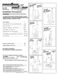
1
PRT
PRT
SAFETY
Observe the safety regulations in
the instruction manual of the Power
Tool to be used or connected to this
attachment. Also observe any
applicable additional safety rules.
Read the following safety
instructions before attempting to
operate this product.
PLEASE KEEP THESE
INSTRUCTIONS IN A SAFE
PLACE.
The attention of UK users is drawn
to The Provision and Use of Work
Equipment Regulations 1998, and
any subsequent amendments.
General
■ Disconnect power tool, when not
in use. Before servicing and
when changing accessories such
as cutters. Disconnect power tool
and attachment from power
supply. Ensure the machine is
switched off before plugging tool
in or connecting to a power
supply.
■ Always mount the power tool,
accessory or attachment in
conformity with the present
instructions.
■ Keep children and visitors away.
Do not let children or visitors
touch the tool, accessory or
attachment. Keep children and
visitors away from work area.
■ Make the workshop child proof
with padlock and master switch.
■ Dress properly. Do not wear
loose clothing or jewellery, they
can be caught in moving parts.
Rubber gloves and non-skid
footwear is recommended when
working outdoors. Wear
protective hair covering to
contain long hair.
■ Consider working environment.
Do not use the product in the
rain or in a damp environment.
Keep work area well lit. Do not
use power tools near gasoline or
flammable liquids. Keep
workshop at a comfortable
temperature so your hands are
not cold.
■ The accessory or attachment
must be kept level and stable at
all times.
■ Keep work area clean. Cluttered
workshops and benches can
cause injuries
oil and sharp edges. Always trail
the power cord away from the
work area.
■ Use the attachment with the
power tools and accessories
specified in this manual only. Do
not force the tool or attachment
to do a job for which it is not
designed.
■ Connect dust extraction
equipment. If devices are
provided for the connection of
dust extraction and collection
facilities, ensure these are
connected and properly used.
■ Secure idle tools. When not in
use, tools should be stored in a
dry and high or locked up place,
out of reach of children.
■ Check all fixing and fastening
nuts, bolts and screws before
use to ensure they are tight and
secure. Periodically check when
machining over long periods.
■ For best control and safety use
both hands on the power tool
and attachment. Keep both
hands away from cutting area.
Always wait for the spindle and
cutter to stop rotating before
making any adjustments.
■ Stay alert. Watch what you are
doing. Use common sense. Do
not operate tools when you are
tired, under the influence of
drugs or alcohol.
■ Always keep guards in place and
in good working order.
■ Personal Protective Equipment
(PPE). All PPE must meet
current UK and EU legislation.
■ Remove any nails, staples and
other metal parts from the
workpiece.
■ Do not leave tools running
unattended. Do not leave tool
until it comes to a complete stop.
■ Maintain tools and cutters with
care. Keep cutters sharp and
clean for better and safer
performance. Do not use
damaged cutters. Follow
instructions for lubricating and
changing accessories. Keep
handles dry, clean and free from
oil and grease.
■ Always clamp workpiece being
machined securely.
■ Maintain accessories. Do not use
damaged accessories. Only use
accessories recommended by
the manufacturer.
■ Check damaged parts. Before
operation inspect the
attachment, the power tool, the
cable, extension cable and the
plug carefully for signs of
damage. Check for alignment of
moving parts, binding, breakage,
mounting and any other
conditions that may effect its
operation. Have any damage
repaired by an Authorised
Service Agent before using the
tool or accessory.
■ Do not use tool if switch does
not turn it on or off. Have
defective switches replaced by
an Authorised Service Agent.
Routing Safety
■ Disconnect router power tool.
When not in use, before
servicing and when changing
accessories such as cutters,
disconnect router and
attachment from power supply.
■ Ensure router cutter has stopped
rotating before changing it.
Never use the spindle lock as a
brake.
■ Remove adjusting keys and
spanners. Form the habit of
checking to see that keys and
adjusting spanners are removed
from the router tool, cutter and
attachment before turning router
on. Make sure cutter can rotate
freely.
■ Check all ball bearing and blade
fixing screws before use to
ensure they are tight and secure.
Periodically check when
machining over long periods.
■ Don't over reach. Keep proper
footing and balance at all times.
■ When using a template guide
bush ensure it cannot come into
contact with collet and nut.
■ Don’t abuse the cable. Never
carry power tool or accessory by
cord or pull it to disconnect from
the socket. Keep cord from heat,
■ Noise. Take appropriate
measures for the protection of
hearing if the sound pressure of
-2-
PRT
85dB(A) is exceeded. Routing
sound pressure may exceed
85dB(A), so ear protection must
be worn.
■ Eye protection. Wear safety
goggles, spectacles or visors to
protect the eyes from ejected
waster particles.
■ Respiratory protection. Wear a
face or dust mask, or powered
respirator. Dust masks/filters
should be changed regularly.
■ Do not switch router on with the
cutter touching the workpiece.
■ The direction of routing must
always be opposite to the
cutter's direction of rotation.
■ After work, release the router
plunge and allow spindle to stop
rotating before putting machine
down.
■ Check before cutting that there
are no obstructions in the path of
the router. When cutting through
the full thickness of the
workpiece, ensure there are no
obstacles beneath workpiece,
and that a sacrificial work
surface is used.
Additional Safety Rules For
Router Cutters
■ Cutting tools are sharp. Care
should be taken when handling
them.
■ Do not drop cutters or knock
them against hard objects. Do
not use cutters that are
damaged.
■ Ensure a No-Volt Release Switch
is fixed to or adjacent to the
attachment and that it is used
correctly.
■ Cutters should be kept clean.
Resin build up should be
removed at regular intervals with
Resin Cleaner®. The use of a dry
lubricant (Trendicote® PTFE) will
act as a preventative. Do not use
PTFE spray on plastic parts.
■ Check the direction of the
workpiece is always opposite to
the cutter's direction of rotation.
■ Cutter shanks should be inserted
into the collet to the mark line on
the shank. This ensures that at
least 3/4 of the shank length is
held in the collet. Do not overtighten the collet nut as this will
score the shank and create a
weakness and fracture point.
■ Observe the correct assembly
instructions in the router
instruction manual for fitting the
collet and nut. Observe the
router power tool manual
instructions on fitting cutters
correctly.
■ It is advisable to periodically
check the collet and collet nut. A
worn, distorted or damaged
collet can cause vibration and
damage the shank, and should
be replaced. Worn collet nuts
should be replaced.
■ Do not take deep cuts in one
pass; take several shallow or
light passes to reduce the side
load applied to the cutter. Too
deep a cut in one pass can stall
the router.
■ Always use cutters with a shank
diameter corresponding to the
size of the collet installed in your
tool.
■ Very small diameter cutters must
be handled and used with care.
■ Always run router cutters at the
spindle speed recommended
and marked accordingly. Ensure
cutter has reached correct speed
before entering workpiece.
Recommended speeds can be
found on the packaging, in cutter
instructions or in the Trend
Routing Catalogue.
Using Routers In A Fixed
Position
■ Always use router cutters in a
router. Router cutters must not
be used in a drill. Drill and boring
bits must not be used in a router.
■ Never use cutters with a
diameter exceeding the
maximum diameter indicated in
the technical data.
■ Always return cutter to its
packaging after use.
■ Do not use awkward or
uncomfortable hand positions.
■ Do not reach underneath table or
put your hands or fingers at any
time in the cutting path while tool
is connected to a power supply.
Useful Advice When
Routing
■ Judge your feed rate by the
sound of the motor.
■ Feed the router at a constant
feed rate. Too slow a feed rate
will result in burning.
■ Take many light passes rather
than one deep cut to reduce the
side load applied to both router
and router cutter.
■ Trial cuts should be made on
waste material before starting
any project.
■ When using some attachments
including a router table or
dovetail jig, the use of a fine
height adjuster is highly
recommended.
■ When using a template guide
bush, ensure there is sufficient
clearance between cutter tip and
inside each of bush. Ensure
cutter and guide bush are
concentric.
■ After work, release the router
plunge to protect the cutter.
■ Always use a push-stick or pushblock for last 300mm of the cut.
■ Whenever possible use a work
holding device or jig to secure
component being machined.
■ Ensure attachment is securely
fitted to the workbench, with
table surface at approximately
hip height.
-3-
Version 3.0 02/2003
PRT
ELECTRICAL SAFETY
Mains Plug Replacement
(UK & Ireland only)
Never use a light socket.
Never connect the live (L) or
neutral (N) wires to the earth
pin marked E or
Always check the condition of the cable and plug
before starting with your work.
Should your mains plug need replacing and you
are competent to do this, proceed as instructed
below. If you are in doubt, contact an authorised
Trend repair agent or a qualified electrician.
■ Disconnect the plug from the supply.
Using an Extension Cable
■ Cut off the plug and dispose of it safely; a
plug with bared copper conductors is
dangerous if engaged in a live socket outlet.
■ If an extension cable is required, use an
approved triple core extension cable suitable
for the power input of this tool (see technical
data). The minimum conductor size is 1.5mm 2.
■ Only fit 13 Amperes BS 1363A approved
plugs fitted with a 13 Amp A.S.T.A approved
BS 1362 fuse (1).
■ When using a cable reel, always unwind the
cable completely.
■ The cable wire colours, or a letter, will be
marked at the connection points of most good
quality plugs. Attach the wires to their
respective points in the plug (see below).
Brown is for Live (L) (2) and Blue is for
Neutral (N) (3).
■ Also refer to the table below.
Cable Length (M)
Cable Rating (Amperes)
■ Before replacing the top cover of the mains
plug ensure that the cable restraint (4) is
holding the outer sheath of the cable firmly
and that the two leads are correctly fixed at
the terminal screws.
13 AMP
1
2
115V
7.5
15A
6A
15
15A
6A
25
20A
6A
30
25A
6A
45
25A
10A
60
25A
15A
Conductor size
(mm2)
0.75
1.00
1.50
2.50
4.00
3
4
For 115V units with a power rating exceeding
1500W, we recommend to use a plug to BS4343
standard.
-4-
Voltage
240V
Cable rating
(Amperes)
6
10
15
20
25
PRT
x1
ITEMS
ENCLOSED
x3
x1
x1
x1
x1
x1
x1
x4
x1
x1
x1
x1
x1
x2
x4
x1
PRT
x1
x1
x1
-5-
x2
PRT
7
DESCRIPTION
OF PARTS
10
3
9
1
Table top
2
Insert rings
3
Back fence
4
Scale
5
Dust port
6
Side pressure guard
7
Top pressure guard
8
Fence cheek
9
Guard
10
Pivot guard lock
11
Floor legs
12
Bench legs
13
Lead on pin
14
Router trigger lock
strap
15
Mitre fence
16
Lead on pin park
17
Pushstick
18
Mitre fence slot
19
Back fence slots/keyhole
20
Push stick park
21
Router clamping screws
22
Lead on pin location hole 17
23
No volt release switch
24
Back fence accessory
fixing point
25
Back fence locking knob
and bolt
15
26
Mitre fence false cheek
fixing screws
22
8
1
4
12
23
6
18
11
25
21
2
14
5
19
13
20
24
26
-6-
16
Prior to assembly and
adjustment always
unplug the router table.
PRT
ASSEMBLY
Fitting Legs
1
2
3
4
-7-
PRT
Router Compatibility See machine screw illustrations on opposite page.
Three machine screws (B) are supplied as standard with the PRT table
Make
Router Model
Screw
x Qty
TREND
TREND
B&Q PERFORMANCE
BOSCH
CMT
DEWALT
DEWALT
DRAPER
ELU
ELU
FELISATTI
MAKITA
PERLES
T3, T5, T5 Mk2
T9
PRO2050R
GOF1600A, 1700ACE
CMT1E
DW613, 614, 615
DW624, 625E
PT1200V
MOF96(E) MK2.
MOF131, 177(E) Mk2
R346EC
RP0910, 1110C
OF808(E) >1999
B
B
B
B
B
B
B
B
B
B
B
B
B
X
X
X
X
X
X
X
X
X
X
X
X
X
2
3
3
3
3
2
3
2
2
3
3
2
2
The following machines require a machine screw pack accessory ref. FIX/KIT/2 (not supplied with table)
Make
Router Model
Screw
x Qty
Csk Size
& Hole
AXMINSTER
ATLAS COPCO
BOSCH
B&Q PERFORMANCE
CASALS
DRAPER
ELU
FELISATTI
FESTO
FLEX
FREUD
HITACHI
HOLZHER
KANGO
MAFELL
MAKITA
MAKITA
METABO
MILWAUKEE
NUTOOL
PERLES
PORTERCABLE
POWER DEVIL
RYOBI
RYOBI
TRITON
SKIL
WADKIN
AW127R●■
OFSE850●■, 1000●■, OFS50●■, OFE710●■
GOF900ACE■, 1300A■, 2000CE
PRO1250R■
FT750■, 1000E■ 2000VCE■
R850V■
MOF96(E) MK1●■, OF97(E)
TP245(E)●■
OF2000(E)●
OFT3121VV■
FT1000E■,FT2000E■
M8(V)■, M12V)■, M12SA■
2335●■, 2355●■, 2356●■
R8550S●■
LO65E●■
3620■
3612BR■,3600B■,3612(C)■
OF1612●■, OFE1812●■
OFSE1000●■
XP12●■
OF808(E) <1998●■
7539, 7519■
PDW5038PR■
R150■, R151■,RE155K■
R500●, R502●, R600(N)●, RE600(N)●,RE601●
TRB001■
1875●■
R500●■
CX2
CX2
DX3
BX3
CX3
CX2
CX2
CX2
CX2
CX2
BX3
AX4
CX2
CX2
CX2
AX2
AX4
CX2
CX2
CX2
CX2
CX3
CX2
AX2
CX3
CX3
CX3
CX3
13mm
13mm
13mm
13mm
13mm
13mm
13mm
13mm
13mm
13mm
13mm
10mm
13mm
13mm
13mm
10mm
10mm
13mm
13mm
13mm
13mm
13mm
13mm
10mm
13mm
13mm
13mm
13mm
Re-drilling of router base by user required.
Re-drilling of insert plate by user required.
+ Packing piece 3mm thick required.
X
X
X
X
X
X
X
X
X
X
X
X
X
X
X
X
X
X
X
X
X
X
X
X
X
X
X
X
6mm
6mm
6mm
6mm
6mm
6mm
6mm
6mm
6mm
6mm
6mm
5mm
6mm
6mm
6mm
5mm
5mm
6mm
6mm
6mm
6mm
6mm
6mm
5mm
6mm
6mm
6mm
6mm
■
Do not mount any power tools
not specified on this list.
●
-8-
PRT
Re-drilling Middle Extrusion Only
Screw Selection
A
M5x16mm
■ Remove middle extrusion from table by turning
cam locks.
■ Remove the plastic base of the router.
Alternatively a photocopy or an outline of the base
can be made of the plastic base instead.
B
M6x16mm
■ Align the centre of the middle extrusion to the
router base and secure them together.
■ Using a centre punch, mark the centres of holes.
■ Drill the required hole size with a suitable metal
cutting drill bit. Best results will be obtained if
your power drill is mounted in a drill stand.
C
M6x25mm
■ Countersink the hole with a countersink bit to a
depth so the heads of the screws are slightly
below the top surface. Clean off any burrs
created.
D
M6x35mm
Mounting Router to Insert Plate
Invert and stand your router onto a suitable
surface. Remove middle extrusion from table by
turning cam locks and place it facing upwards
onto the base of your router. Screws are supplied
for TBC routers, see opposite chart. For other
makes of router, re-drilling of the router base or
insert plate will be required. Appropriate machine
screws will be required, see chart, these are
available as an accessory Ref. FIX/KIT/2.
Re-drilling Router Base Only
■ Invert and stand your router onto a suitable
surface.
■ Remove middle extrusion from table by
turning cam locks and place it facing upwards
onto the base of your router.
■ Adjust position of the middle extrusion to
centralise.
Re-drilling both Middle Extrusion
and Router Base
■ Invert the router and lay the middle extrusion onto
the upturned base.
■ Clamp the middle extrusion and router base
together with two cramps.
■ Ensuring that the drill bit will not foul any webbing
or fixtures on the router base, drill with a 6mm
diameter metal cutting drill bit into the middle
extrusion and through the router base two holes.
■ Unclamp the router base and middle extrusion.
■ Countersink the middle extrusion holes with a
countersink bit to a depth so the screw heads are
slightly below the top surface. Clean off any burrs
created on both the middle extrusion and router
base.
■ Ensure that the holes you are about to drill in
the base do not interfere with any of the
features on the router or any webbings in the
casting of the router base. A slight turning of
the router may be required to miss such
obstructions.
■ Mark the centre of the holes onto the base.
■ Remove middle extrusion and mark the centre
of the holes with a centre punch.
■ Drill a hole at these points with a 6mm
diameter drill bit.
■ Clean up edges of holes if required.
-9-
PRT
Fitting Insert
Rings
=
20mm
=
16mm
30mm
35mm
=
50mm
1
54mm
1:1
SCALE
=
64mm
2
68mm
=
90mm
-10-
86mm
PRT
Fitting Back Fence
2
2
1
1
-11-
PRT
Fitting Top Guard & Top Pressure
1
2
1:1
SCALE
10mm
max.
1:1
SCALE
1:1
SCALE
5mm
max.
1:1
SCALE
-12-
PRT
Fitting Side
Pressure
5mm
Position 1
Position 2
70mm
Position 3
-13-
PRT
Fitting Mitre Fence
-14-
PRT
Dust Extraction Fitting Hose
-15-
PRT
OPERATION
No-Volt Release
Switch
1
Plug machine into
trailing socket.
2
Put plug of switch
into mains supply.
3
Switch on router
4
Press green
button to switch
on. To switch off
press red button.
ON
OFF
Isolate from
power supply
when making
any adjustments.
-16-
PRT
A
Back Fence
Adjustment
3
To adjust fence
cheeks loosen four
back knobs (B).
Slide cheeks in and
out to suit cutter.
Leave gap of 3mm.
4
B
A
Lock cheeks by
tightening four
knobs (B).
3mm
max.
-17-
3mm
max.
Max 121mm Position 4
Lock fence position
by tightening the
two knobs (A).
Max 84mm Position 3
2
Max 43mm Position 2
Adjust back fence
position by
loosening two knobs
(A) and pushing
fence forwards or
backwards.
Max 10mm Position 1
1
A
PRT
Edge Moulding
and Grooving
1
Isolate from
power source.
2
Fit cutter.
3
Set back fence
position.
4
Set top and side
pressures.
5
Fit guard.
6
Check all knobs
are tight.
7
Plug into power
supply.
8
Switch on.
9
Feed right to left.
✓
10 Switch off.
✗
-18-
PRT
Stopped
Moulding
1
Isolate from power
supply.
2
Fit cutter.
3
Set back fence
position. Fit some
stops to back fence
using cramps.
4
Fit guard.
5
Check all knobs are
tight
6
Plug into power
supply.
7
Switch on.
8
Drop material
against infeed stop
A and pivot into
cutter.
9
B
A
B
A
B
A
Feed right to left,
until reaching
outfeed limit stop B.
10 Pivot at outfeed
stop.
11 Switch off.
-19-
PRT
Mitre Fence
1
Isolate from power
supply.
2
Fit cutter.
3
Adjust angle of mitre
fence by loosening
knob and turning
protractor head to
line up angle
required with arrow.
4
Place component
onto mitre fence.
5
Plug into power
supply.
6
Feed right to left
holding component
securely.
7
Switch off.
-20-
PRT
Lead-on Pin
1
Isolate from power
supply.
2
Fit lead-on pin into
threaded hole using
a slotted screwdriver.
3
Move back fence
back.
4
Fit self guided cutter.
5
Fit top guard.
6
Plug into power
supply.
7
Support component
onto the lead-on pin
and swing into cutter
and contact bearing
guide.
8
Mould component.
9
Switch off.
Guard removed
for clarity.
Ensure guard is
fitted when using
self guided cutters.
-21-
PRT
OPTIONAL ACCESSORY
COPY FOLLOWING ATTACHMENT PRT/01
For use with unguided router cutters.
Lead on pin must
be fitted.
-22-
PRT
MAINTENANCE
The router table has been designed to operate
over a long period of time with a minimum of
maintenance. Continual satisfactory operation
depends upon proper tool care and regular
cleaning.
■ Replace the cutter insert when worn out.
■ Cleaning
Keep the grooves clear of sawdust.
Regularly clean the table with a soft cloth.
■ Lubrication
Your router table requires no additional
lubrication.
RECYCLING
Router table, accessories and packaging should
be sorted for environmentally friendly recycling.
GUARANTEE
The router table carries a manufacturers
guarantee in accordance with the conditions on
the enclosed guarantee card.
-23-
PRT
PRT - SPARE PARTS LIST
No.
Qty.
1
2
3
4
5
6
7
8
9
10
1
0
1
1
1
1
1
1
4
1
0
0
1
1
1
1
2
2
4
2
8
4
1
1
7
1
1
1
1
4
2
1
4
1
4
1
2
1
1
1
1
2
0
4
11
12
13
14
15
16
17
18
19
20
21
22
23
24
25
26
27
28
29
30
31
32
33
34
35
36
37
38
39
40
41
42
V1.0 05/2003
Desc.
Ref.
Extrusion Top Middle
Back Fence Complete
Extrusion Side Front
Extrusion Side Back
Extrusion Top Front
Extrusion Side Left
Extrusion Side Right
Extrusion Top Back
Extrusion Bracket Front
No Volt Release Switch 230V UK Plug
No Volt Release Switch 230V Euro
No Volt Release Switch 115V UK
Pivot Guard Housing
Pivot Guard Slider
Pivot Guard Clamping Wedge
Pivot Guard Cam Locking Lever
Cheek End Cap Angled
Cheek End Cap
Extrusion Cam Lock
Finger Pressure Only
Lobe Knob 40mm Dia M8 Female
Lobe Knob 40mm Dia M8 x 15mm Male
Lobe Knob 30mm for Guard M8 Female
Clear Visor
Screw Self Tapping Csk 3mm x 9.5mm Pozi
Insert Ring 20mm ID
Insert Ring 35mm ID
Insert Ring 54mm ID
Insert Ring 68mm ID
Extrusion Support Bracket
Extrusion Vertical Support
Pivot Guard Spacer Plate
Extrusion Lock Screw M6 x 27mm Slot
Table Frame Welded
Set Screw Hex M8 x 22mm
Side Pressure Holder
Back Fence Fixing Bolt M8
Pivot Guard Slider Bolt M8 x 150mm
Pivot Guard Slider Spring
Pivot Guard Hinge
Mitre Fence Complete
Sliding Extrusion Cheek
Side Finger Pressure Assembly
Washer Rectangle for Scale
WP-PRT/01
WP-PRT/02
WP-PRT/03
WP-PRT/04
WP-PRT/05
WP-PRT/06
WP-PRT/07
WP-PRT/08
WP-PRT/09
WP-PRT/10
WP-PRT/EURO
WP-PRT/10L
WP-PRT/11
WP-PRT/12
WP-PRT/13
WP-PRT/14
WP-PRT/15
WP-PRT/16
WP-PRT/17
WP-PRT/18
WP-PRT/19
WP-PRT/20
WP-PRT/21
WP-PRT/22
WP-PRT/23
WP-PRT/24
WP-PRT/25
WP-PRT/26
WP-PRT/27
WP-PRT/28
WP-PRT/29
WP-PRT/30
WP-PRT/31
WP-PRT/32
WP-PRT/33
WP-PRT/34
WP-PRT/35
WP-PRT/36
WP-PRT/37
WP-PRT/38
MITRE/1
WP-PRT/40
PRESSURE/2
WP-PRT/42
-24-
PRT
PRT - SPARE PARTS LIST
No.
Qty.
43
44
45
46
47
48
49
50
51
52
53
54
55
56
57
58
59
60
61
62
63
64
65
66
67
68
69
70
71
72
73
74
75
76
77
78
79
80
81
82
83
1
2
1
2
1
2
4
1
4
8
20
1
2
8
2
2
1
2
4
1
8
4
1
4
13
1
20
4
1
4
4
3
20
1
1
1
1
1
3
3
1
V1.0 05/2003
Desc.
Ref.
Cam Lever Lock Bush 12mm
Pushstick Park Screw M4 x 20mm Pozi
Lead-On Pin M6
Pushstick Park Bush
Cam Lever Set Screw M8 x 60mm
Scale
Cheek T Slot Bolt M8 x 27MM
Washer 8.5mm x 15.8mm x1.8mm
Set Screw Hex Bolt M8 x 35mm
Set Screw Hex Bolt M8 x 16mm
Machine Screw Cap M8 x16mm Socket
Router Switch Lock
Machine Screw Cap M6 x 16mm Socket
Screw Hex Bolt M6 x 8mm Socket
Machine Screw Csk M6 x 20mm Socket
Screw Self Tapping Pan No 12 x 32mm Pozi
Push Stick
Screw Self Tapping Pan 4.2mm x 13mm Pozi
Machine Screw Cap M4 x 6mm Socket Slot For Scale
Nut Hex M8
Nut Nylon M8
Short Leg Plastic Foot 30mm
Back Fence Casting
Nut Hex M6
Washer 6.6mm x 12mm x 1.6mm
Spacer 8mm Bore
Washer 8.3mm x 24mm x 1.8mm
Pin For Extrusion Cam Lock
Cam Lock Washer 12mm
Floor Leg
Floor Leg Rubber Foot
Machine Screw Csk M6 x18mm Slot
Washer 8.3mm x 15.8mm x 1.6mm
Washer 6.4mm x 16mm x 1.0mm
Mitre Fence Location
Mitre Fence Body
Mitre Fence Knob M6 x 20mm Male
Mitre Fence Rail and Index Head
Nut Hex M5
Machine Screw Pan M5 x 20mm Slot
Instruction Manual
WP-PRT/43
WP-PRT/44
WP-PRT/45
WP-PRT/46
WP-PRT/47
WP-PRT/48
WP-PRT/49
WP-WASH/15
WP-BOLT/10
WP-BOLT/11
WP-SCW/92
PRT/LOCK
WP-SCW/87
WP-SCW/88
WP-SCW/89
WP-SCW/106
PUSHSTICK/1
WP-PRT/60
WP-PRT/61
WP-NUT/08
WP-NUT/09
WP-PRT/64
WP-PRT/65
WP-NUT/06
WP-WASH/11
WP-PRT/68
WP-PRT/69
WP-PRT/70
WP-PRT/71
WP-PRT/72
WP-PRT/73
WP-SCW/86
WP-WASH/15
WP-PRT/76
WP-PRT/77
WP-PRT/78
WP-PRT/79
WP-PRT/80
WP-NUT/05
MANU/PRT
MANU/PRT
Copy Follower Attachment
PRT/01
PRT/01 (Optional)
83
1
-25-
PRT
V1.0 05/2003
PRT - SPARE PARTS DIAGRAM
27
74
31
26
24
70
1
25
17
67
8
66
44
44
5
1
59
52
46
63
28
67
61
48
56
60
46
42
53
10
4
6
75
53
9
33
7
3
63
53
53
53
75
29
51
51
20
75
32
72
63
PRT
83
64
54
73
-26-
45
PRT
V1.0 05/2003
PRT - SPARE PARTS DIAGRAM
2
47
50
43
14
36
37
19
57
30
75
71
13
11
12
38
55
68
21
23
40
23
35
65
19
15
18
22
62
49
16
79
19
75
76
41
18
79
58
34
81
39
82
77
80
-27-
83
MANU/PRT v1.0
RECYCLABLE
Trend Machinery & Cutting Tools Ltd.
Odhams Trading Estate St Albans Road
Watford WD24 7TR England
Enquiries: _________________0800 487363
Technical Support: ___0044 (0) 1923 224681
Fax: _______________0044 (0) 1923 236879
Email: [email protected]
web: ___________www.trendmachinery.co.uk
© Copyright Trend 2003. No part of this publication may be reproduced, stored or transmitted in any form without prior permission.
Our policy of continuous improvement means that specifications may change without notice. Trend Machinery and Cutting Tools
cannot be held liable for any material rendered unusable or any form of consequential loss. E&OE
® All trademarks acknowledged.