1
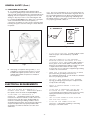
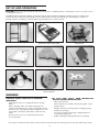
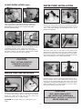
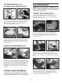
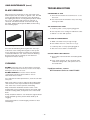
CUTTING HEAD ASSEMBLY
Support Post
Fig F1
Fig G4
Fig G3
Slide the Blade Guard over the support post on the motor
assembly (Fig G3). Secure by tightening the provided
adjustment knob (Fig G4).
Fig F2
To attach the Cutting Head (Fig F1), find the Motor
Support Shaft, loosley inserted in the bottom side of the
unit (Fig F2).
DIAMOND BLADE INSTALLATION
CHANGING THE BLADE:
WARNING! Disconnect the power supply before making
adjustments, maintenance, cleaning or replacing the
blade!
Fig F3
DIAMOND BLADES
Fig F4
Insert the Support Shaft into the Motor Support Arm (Fig
F3). Use provided Shaft Bolt with lock washer and washer,
then tighten (Fig F4).
Fig F5
1.
Use 10” diameter Continuous Rim Wet Diamond
Blades with this saw.
2.
10” Blades with arbor holes of 5⁄8” diameter will fit this
saw.
Fig F6
Fig H1
To stabalize the pivoting Cutting Head, use the provided
large plastic knob and washer (Fig F5), secure the motor
unit to the Vertical Adjustment Bracket (Fig F6).
Fig H2
Tilt the Blade Guard to the highest position and tighten
the adjustment knob (Fig H1). Use the provided wrench,
or adjustable wrench, to remove the blade shaft nut and
outer flange (Fig H2).
BLADE GUARD ASSEMBLY
Blade
Rotation
Fig G1
Fig H4
Fig H3
Place the blade onto the shaft, with the direction arrow
pointing in the same direction of rotation (Fig H3).
Replace the outer flange and blade shaft nut (Fig H4).
Fig G2
The Blade Guard must be installed before the Diamond
Cutting Blade. The Blade Guard (Fig G1) will be attached
using the 11⁄2" adjustment knob (Fig G2).
- 10 -