1
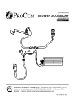
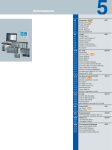
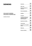
Blower for the FBD28 series
& FBD32 series Fireplace
systems
PACKAGE CONTENTS
Before beginnig assembly of product, make sure all parts are present. Compare
parts with package contents list and diagram under. If any part is missing or
damaged, do not attempt to assemble, install or operate the product. Contact
customer service for replacement parts.
Estimated Assembly Time: 30 minutes.
Tool List For Assembly (Not Included):
KEY NO
DESCRIPTION
QUANTITY
1
PHILLIPS SCREWDRIVER
1
2
WIRE CUTTING PLIERS
1
Part List
KEY NO
PART NUMBER
DESCRIPTION
QUANTITY
1
XB001-01
Power Cord
1
2
XB002-01F
Blower
1
3
XB003-01
Temperature Sensor
1
4
XB004-01F
Connect Wire
1
5
PF06-0400-A
Rocker Switch
1
6
M4.2×8
Screw
6
7
4.0×8
Screw
1
8
VL057-03
Cable Tie
6
IMPORTANT: Read all instructions and warnings carefully before starting installation.
Failure to follow these instructions may result in a possible electric shock, fire hazard
and will void the warranty.
Question, problems, missing parts? Before returning to your retailer, call our customer service
department at 1-877-866-5989 in English.
PC-FANFIB-0901
Safety Information
1.
Read all instructions before using this appliance.
2.
If possible always unplug this appliance when not in use.
3.
Do not operate any heater with a damaged cord or plug or after the appliance malfunctions, has been dropped or
damaged in any manner.
4.
Any repairs to this appliance should be carried out by a qualified service person.
5.
Under no circumstances should this appliance be modified. Parts having to be removed for servicing must be
replaced prior to operating this appliance again.
6.
Do not use outdoors.
7.
This heater is not intended for use in bathrooms, laundry areas and similar indoor locations. Never locate this
appliance where it may fall into a bathtub or other water container.
8.
Do not run cord under carpeting. Do not cover cord with throw rugs, runners or the like. Arrange cord away from
traffic areas and where it will not be tripped over.
9.
To disconnect this appliance, turn controls to the off position, then remove plug from outlet.
10.
Connect to properly grounded outlets only.
11.
This appliance, when installed must be electrically grounded in accordance with local codes, with the current
CSA C22.1 Canadian Electrical codes or for USA installations, follow local codes and the National Electric Code,
ANSI/NFPA No. 70.
12.
Do not insert or allow foreign objects to enter any ventilation or exhaust opening as this may cause an electric
shock, fire or damage the appliance.
13.
To prevent possible fire, do not block air intakes or exhaust in any manner.
14.
Use this appliance only as described in this manual. Any other use not recommended by the manufacturer may
cause fire, electric shock or injury to persons.
15.
Avoid the use of an extension cord because of the risk of overheating the cord and the risk of fire. Extension cords
are for temporary use only. If an extension cord must be used, it must be UL/CSA certified, rated at 15A (1875W),
125V maximum with 14 AWG minimum and constructed of two current carrying conductors with ground. A heavy
duty extension cord with the shortest length possible for the connection is recommended and must not be longer
than 50 ft. (15.2 m). Do not coil or cover the extension cord.
2
Exploded Drawing
3
1
2
5
4
6
8
7
3
Assembly Procedure for Item FBD28 Series Optional Parts:
NOTICE: Shut off gas heater during the following blower installation.
Figure 1 Remove upper fire box by
Figure 2 Unscrew two screws on
Figure 3 Fix temperature sensor to
unscrewing left/right screws on the
heat insulation board cover and
heat insulation board cover as
fire box.
draw it out.
shown in the figure.
.
protecting
board
Wire Fixture
Figure 4 Insert wires into the space
Figure 5 Connect temperature sensor
Figure 6 Insert blower assembly into
between wire protecting board and
with lead; Install the cover according to the bottom space of burner pan
shell; Fix the wires to the top cover
Figure 2, then fix the upper fire box
according to Figure 7. Pay attention
with wire fixture.
according to Figure 1.
not to touch wires inside.
Figure 7 Set Blower plane and fix it
Figure 8 Fix Blower with one screw,
Figure 9 Fix the wires, which is
onto two brackets of shell board.
after manually install it into slots.
matched with metal wafer, to the
Install Bower
into slots
Please refer to Figure 6. Make sure
shell with three screws.
Blower is installed into the slots.
4
Figure 10 Fix the grounding.
Figure 11 Insert the blower.
Figure 12 Connect the port and shell
board with linker (male port) into the
three wires preset aside screws
(please refer to linker (female port)
preset (red, yellow and black) with
grounding label); add gasket aside.
switch separately. Codes between
shell board and on wires must
correspond grounding port with those
on the rocke
Figure 13 Push the rocker switch into
Figure 14 Insert the male port, which
the hole on the panel.
is on the black power supply wire
(marked with P2), into the
corresponding female port
(marked with P2).
Figure 15 Insert the female port,
which is on the white power supply
wire (marked with P1), into the
corresponding male port.
(marked with P1).
5
Assembly Procedure for Item FBD32 Series Optional Parts:
NOTICE: Shut off gas heater during the following blower installation.
Figure 1 Remove upper fire box by
Figure 2 Unscrew two screws on
Figure 3 Fix temperature sensor to
unscrewing left/right screws on the
heat insulation board cover and
heat insulation board cover as
fire box.
draw it out.
shown in the figure.
.
protecting
board
Wire Fixture
Figure 6 Unscrew and remove
Figure 4 Insert wires into the space
Figure 5 Connect temperature sensor
between wire protecting board and
shell; Fix the wires to the top cover
with lead; Install the cover according to panel on the left side.
Figure 2, then fix the upper fire box
with wire fixture.
according to Figure 1.
Install Bower
into slots
Figure 7 Insert blower assembly
Figure 8 Set Blower plane and fix it
Figure 9 Fix Blower with one screw,
into the bottom space of burner pan
onto two brackets of shell board.
after manually install it into slots.
according to Figure 8. Pay attention
Please refer to Figure 7. Make sure
not to touch wires inside.
Blower is installed into the slots.
6
Figure 10 Fix the wires, which is
Figure 11 Fix the grounding.
Figure 12 Insert the blower.
matched with metal wafer, to the
shell with three screws.
Figure 13 Connect the port and shell
Figure 14 Push the rocker switch
Figure 15 Insert the male port, which
board with linker (male port) into the
into the hole on the panel.
is on the black power supply wire
three wires preset aside screws
(marked with P2), into the
(please refer to linker (female port)
corresponding female port
preset (red, yellow and black) with
(marked with P2).
grounding label); add gasket aside.
switch separately. Codes between
shell board and on wires must
correspond grounding port with those
on the rocker.
Figure 16 Insert the female port,
which is on the white power supply
wire (marked with P1), into the
corresponding male port.
(marked with P1).
7
Electrical Connection
A 15 amp, 120 Volt, 60 Hz circuit with a properly grounded outlet is required. Preferably, the fireplace will be on a
dedicated circuit as other appliances on the
same circuit may cause the circuit breaker to trip or the fuse to blow when the heater
is in operation. Plan the installation to avoid the use of an extension cord. Extension cords are for temporary use only. If
an extension cord must be used, it must be UL/CSA certified, rated at 15A (1875W), 125V maximum with 14 AWG
minimum and constructed of two current carrying conductors with ground. A heavy duty extension cord with the shortest
length possible for the connection is recommended and must not be longer than 50 ft. (15.2 m). Do not coil or cover the
extension cord.
Electrical outlet wiring must comply with local building codes and other applicable regulations to reduce the risk
of fire, electrical shock and injury to persons.
Do not use this fireplace if any part of it has been under water. Immediately call a qualified service technician to
inspect the fireplace and replace any part of the electrical system which has been under water.
Grounding Instructions
This heater is for use on 120 volts. The cord has a plug as shown at A in Figure 1. An adapter as shown at C is
available for connecting three-blade grounding-type plugs to two-slot receptacles. The green grounding lug extending
from the adapter must be connected to a permanent ground such as a properly grounded outlet box. The adapter
should not be used if a three-slot grounded receptacle is available.
8
Operating Instructions
Using Rocker Switch, turn blower on and check for operation. Turn on Rocker Switch to the desired position. In the
MAN position it will remain constantly on. AUTO position will be controlled by the Temperature Sensor. To stop the
operation turn Rocker Switch to the OFF position.
Electrical Wiring Diagram
Any electrical repairs or rewiring of this unit should be carried out by a licensed electrician in accordance with national
and local codes.
If repairing or replacing any electrical component or wiring, the original wire routing, color coding and securing
locations must be followed.
2
WHITE
~ 120V
60Hz
GREEN
BLACK
BLACK
1
AUTO OFF MAN
5
1.Power Cord
2.Bushing Strain Relief
3.Fan
4.Temperature limiter
5.Rocker Switch
RED
t°
FAN
4
3
WARNING: Disconnect Power Before Servicing.
Any electrical re-wiring of this appliance must be done by a qualified electrician. This wiring must be done in
accordance with local codes and/or in Canada with the current CSA C22.1 Canadian Electrical Code, and for US
installations, the National Electrical Code ANSI/NFPA NO 70.
9
Maintenance of Motors
Always disconnect the appliance from the main power supply and allow it to cool before any servicing operation.
The motors used on the fan heater and flame blower are pre-lubricated for extended bearing life and require no further
lubrication. However, periodic cleaning/vacuuming of the appliance around the air intake and exhaust, as well as the fan
heater is recommended. For heavy or continuous use, periodic cleaning must be done more frequently. If the heater
blows alternating cold and warm air, check the fan for free movement and for debris restricting air flow. If the fan does
not move freely, the unit must be turned off and the fan replaced immediately in order to prevent further damage
to the unit.
WARNING: Make sure the power is turned OFF before proceeding.
10