1
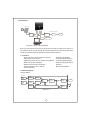
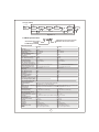
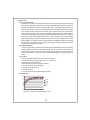
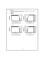
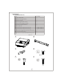
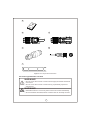
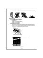
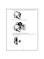
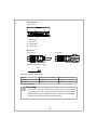
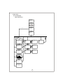
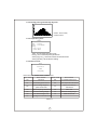
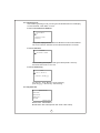
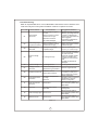
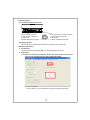
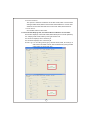
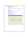
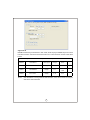
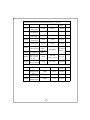
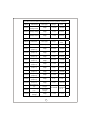
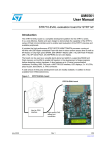
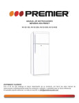
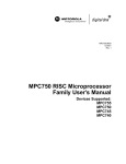
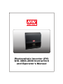
Photovoltaic Inverter (PV)
GSI-3000,4600 Instruction
and Operator's Manual
GSI-3000,4600 Introduction
and Operator's Manual
Table of Contents
0.Notes on this Manual ............................................................................. 1
0.1 About this Manual ............................................................................. 1
0.2 Safety Symbols Used........................................................................ 1
1.Safety Guidelines ................................................................................... 2
2.Introduction ............................................................................................ 2
2.1 Features........................................................................................... 2
2.2 Block Diagram.................................................................................. 2
2.3 Main Specification............................................................................ 3
3.Appearance............................................................................................ 3
3.1 Front View........................................................................................ 3
3.2 Electrical & Communication Connections.......................................... 3
4.Functions ............................................................................................... 5
4.1 Brief Description............................................................................... 5
4.2 Safety Features................................................................................ 5
4.3 Control............................................................................................. 5
4.4 Efficiency.......................................................................................... 5
4.5 Derating........................................................................................... 6
5.Installation ............................................................................................ 7
5.1 Package Check List .......................................................................... 7
5.2 Choosing Installation Location.......................................................... 8
5.3 Wall Mounting................................................................................... 10
5.4 Electrical Connections...................................................................... 12
Jan. 2015 Version 1
GSI-3000,4600 Introduction
and Operator's Manual
Table of Contents
5.5 Power ON/OFF ................................................................................. 14
5.6 Disassembly..................................................................................... 15
6.Operation ............................................................................................... 16
6.1 LCD Display ..................................................................................... 16
6.2 Buttons ............................................................................................ 17
6.3 LED Indicators.................................................................................. 17
6.4 Operation Procedure ........................................................................ 17
7.Troubleshooting ..................................................................................... 21
8.Communication ...................................................................................... 22
8.1 Communication Connections ............................................................ 22
8.2 Wiring Method .................................................................................. 22
9.Monitoring Software .............................................................................. 22
9.1 Installation ....................................................................................... 22
9.2 Operation ......................................................................................... 22
Appendix A:
MODBUS data physical address ............................................................. 25
0.Notes on this Manual
0.1 About this Manual
The intention of this manual is to provide instructions for the mounting, installation,
maintenance and troubleshooting. Please store with system documentations
and ensure that it is accessible at all times.
0.2 Safety Symbols Used
Warning: Indicates a hazardous situation which could result in death
or serious injury if not avoided.
Caution: Indicates a situation that can result in damage to the unit or
other equipment if not avoided.
Electric Shock Hazard: Indicates a hazardous situation which
can result in electrical shock if not avoided.
Burn Hazard: Indicates a hazardous situation which can result in
scalds or burns if not avoided.
1.Safety Guidelines
◎GSI is a grid-tied PV inverter that converts direct current (DC) electricity into
alternating current (AC) with an ability to synchronize to interface with a utility grid
line. Please do not connect anything other than a PV module source to the inverter.
◎This is a transformerless inverter, please make sure PV modules connected to
the unit have an IEC61730 class A rating.
◎Risk of electrical shock and energy hazard. All failures should be examined by a
qualified technician. Please do not remove the case of the inverter by yourself!
◎Please do not install the inverter in places with high moisture or near water.
◎Please do not install the inverter in places with high ambient temperature, under
direct sunlight, or near fire source.
◎Please do not stack any object on the inverter as it may impede heat dissipation.
◎Comply with the local regulations, standards, and operational procedures when
setting up the PV inverter.
◎Electrical Shock Hazard :
To prevent electrical shock while repairing, please make sure all AC & DC switches
are disconnected.
◎Case Surface :
The Body of PV inverter may possess very high temperatures while operating,
please refrain from contact.
1
2 . Introduction
PV Panel
AC watt-hour meter
DC
distribution
box
AC
distribution
box
PE
RS485 to
USB RS232
RS485
KW-hr
Utility grid
Utility Company
PC
Figure 2.1 System block diagram
E n er g y i s t r an sf e r re d f r o m t h e P V m o d ul e t o t h e G S I a s a D C i np u t. N e xt i t i s
converted to an AC output through the GSI and transferred to the utility grid. Data
can be acquired through the RS-485 communication interface.
2 .1 Features
‧True sine wave current output (THD<3%)
‧High efficiency up to 96%
‧IP65 design for indoor or outdoor installations
‧Multi-string input and MPPT
‧RS485 communication interface
‧Optional DC disconnect switch
‧5 years warranty
‧Graphic LCD display
‧Anti-islanding protection
‧Transformerless design
‧With internal ground fault
detector
‧Monitoring software
2 . 2 Block Diagram
Grid Type (4600VA)
PV string A
EMI
FILTER
MPPT
INVERTER
PV string B
EMI
FILTER
LINE
FILTER
EMI
FILTER
Utility
GFCI
MPPT
PE
RS485
Dual-DSP
Figure 2-2
2
LCD
DISPLAY
Grid Type (3000VA)
PV string
EMI
FILTER
MPPT
LINE
FILTER
INVERTER
EMI
FILTER
Utility
GFCI
RS485
PE
LCD
DISPLAY
Dual-DSP
Figure 2-3
2 . 3 Main Specification
GSI 4600 A
:Without DC disconnect switch
A :With DC disconnect switch
Grid-tied Solar Inverter
O/P Wattage: 3000VA
4600VA
SPECIFICATION
DC Input
Max. Input Power
Input Voltage Range
MPPT Range
Number of MPPT Tracker
Max. Input Current
AC Output
Rated Output Power (Typ.) (@230V, 50Hz)
Max. Output Power (Typ.)
AC Voltage Range
AC Grid Frequency
Max. Output Current (Typ.)
Power Factor at Rated Power
Adjustable Displacement Power Factor
THD(at rated power) (Typ.)
DC Current Injection (Typ.)
AC Connection
Efficiency
Max. Efficiency (Typ.)
Euro Efficiency (Typ.)
Protection
DC Reverse Polarity
Over Temperature
AC Short
Residual-Current Monitoring Unit
Over Voltage Category Main
Over voltage Category PV
Standards Compliance
Grid Certificate
LVD
EMI Conduction & Radiation
EMS Immunity
Environment
Working Temperature
Working Humidity
Maximum Altitude Rating
Pollution Degress
Storage Temperature / Humidity
Vibration
Protection Degree
General Data
DC Disconnect Switch
Cooling
Interface
Topology
Display
Dimension(L*W*H)
Weight
GSI-3000
GSI-4600
3160W
100 ~ 550VDC
125 ~ 500VDC
1
1*16A
4850W
100 ~ 550VDC
125 ~ 500VDC
2
2*10A
3000VA
3000VA
180 ~ 264VAC
50±5Hz / 60±5Hz
13.1A
>0.99
0.9 overexcited ~ 0.9 underexcited
<3%
<0.5% of rated output current
Single Phase
4600VA
4600VA
180 ~ 264VAC
50±5Hz / 60±5Hz
20A
>0.99
0.9 overexcited ~ 0.9 underexcited
<3%
<0.5% of rated output current
Single Phase
>96%
>95%
>96%
>95%
Yes
Yes
Yes
Yes
Ⅲ
Ⅱ
Yes
Yes
Yes
Yes
Ⅲ
Ⅱ
VDE-AR-N 4105, CGC NB/T 32004, IEEE 1547
TUV EN62109-1,-2, CGC NB/T 32004
EN61000-6-3, EN61000-3-2,-3, CGC NB/T 32004 EN61000-6-3, EN61000-3-11,-12, CGC NB/T 32004
EN61000-6-2 (include EN61000-4-2,3,4,5,6,8,11), EN61000-4-12,-14,-18
-25 ~ +60℃
-25 ~ +60℃
4 ~ 100% RH non-condensing
4 ~ 100% RH non-condensing
2000m
2000m
Ⅲ
Ⅲ
-30 ~ +70℃
-30 ~ +70℃
10 ~ 500Hz, 2G 10min./1cycle, 60min. each along X, Y, Z axes
IP65
IP65
Optional
Convection
RS485
Transformerless
LED / Graphic LCD
438*390*158mm (L*W*H)
20Kg; 1pcs/21Kg/2.16CUFT
Optional
Forced Air
RS485
Transformerless
LED / Graphic LCD
438*390*158mm (L*W*H)
20Kg; 1pcs/21Kg/2.16CUFT
3
3 . Appearance
3 . 1 Front View
:Power indicator, refer to chapter 6
for instructions
FAULT :Failure indicator, refer to chapter 6
for instructions
ENTER:Enter, refer to chapter 6 for instructions
UP
:Enter, refer to chapter 6 for instructions
DOWN :Down, refer to chapter 6 for instructions
ESC :Exit, refer to chapter 6 for instructions
PWR
PWR
FAULT
EN TER U P DOWN ESC
Figure 3-1
3 .2 Electrical and Communication Connections
GSI-4600
GSI-4600A
Figure 3-2
Figure 3-3
GSI-3000
GSI-3000A
Figure 3-4
1
2
3
4
Figure 3-5
5
1 : DC Switch:DC input switch
2 : PV String A DC connector:DC channel A input
connector
CH1
CH2
Figure 3-6
3 : PV String B DC connector:DC channel B input
connector
4 : Remote Port : Communication connector
(CH1: linked to PC)
(CH2: linked to utility company)
5 : AC Connector:AC output connector
4
4.Functions
4.1 Brief D escription
The GSI is a single phase grid-tied PV inverter, which is unlike to the stand-alone
PV inverter in the sense that it does not need an external battery, which is expensive
and bulky; furthermore reducing the sizeable cost of maintaining this battery. The
GSI can effectively convert photovoltaic DC power harvested from the PV module
to AC power which is fed back to the utility grid, reaching the goal of generating
and conserving energy. The control unit employs digital signal processing (DSP),
using advanced digital control methods and algorithms to increase converting
efficiency and provide additional features. Power-level circuitry utilizes single
stage high frequency switching IGBT, which has the merit of simple structure and
high efficiency. PV inverter system can be remotely controlled by software, providing
the user with convenient means of power monitoring and data collection without
an additional monitoring system.
4.2 Safety Features
To ensure the safety of personnel, GSI has an internal leakage current monitoring
system. When a failure occurs and leakage current is present, the system will
activate and detach connection to the utility grid. Whether under intentional or
unintentional contact, this protection mechanism will trigger to prevent electrical
shock.
4.3 Control
GSI provides the following inverter control functions :
1.Parameter Monitoring (voltage, current, frequency).
2.Utility grid synchronization.
3.Maximum Power Point Tracking (MPPT).
4.Input and output current limiting.
5.Temperature monitoring.
6.Graphic display.
7.Communication (through RS485 interface).
4.4 Efficiency
98
96
94
92
400VDC
90
380VDC
88
300VDC
86
250VDC
84
82
5%
10% 15% 20% 25% 30% 50% 70% 100%
Figure 4-1 Efficiency characteristic curve
5
4. 5 Derating
When the input voltage is low or when ambient temperature is high, the GSI-3000,
4600 will automatically derate the output.
Derating
GSI-4600
100
100
85
80
75
65
60
50
40
25
20
10
-25
0
10
20
30
40
50
60
70
(HORIZONTAL)
50
125
150
AMBIENT TEMPERATURE (℃)
200
245
300
350
400
450
500
550
INPUT VOLTAGE (V)
Figure 4-2 GSI-4600 Load vs.
Ambient Temperature Curve
Figure 4-3 GSI-4600 Load vs.
Input Voltage Curve
GSI-3000
100
100
85
80
75
65
60
50
40
25
20
-25
10
0
10
20
30
40
50
60
70
(HORIZONTAL)
AMBIENT TEMPERATURE (℃)
50
125
150
200
250
300
350
400
450
500
550
INPUT VOLTAGE (V)
Figure 4-4 GSI-3000 Load vs.
Ambient Temperature Curve
Figure 4-5 GSI-3000 Load vs.
Input Voltage Curve
6
5.Installation
5.1 Package Check List
Item
Quantity
A GSI-3000,4600
1
B Wall Mounting Bracket
1
C Plastic Anchor
3
D Mounting Bracket Screw
2
E Rear Panel Support Screw
1
F Screw for Plastic Anchor
3
G User Manual
1
H MC4 DC Wire End Connector (+)
2 (GSI-3000*1)
I MC4 DC Wire End Connector (-)
2 (GSI-3000*1)
J Wieland Flange Wire End AC Connector
1
K Communication Wire
2
L MC4 DC Connector Disassembling Tool
1
Table 5-1
A
B
C
D
M6*8
E
F
7
G
H
I
J
K
L
Figure 5-2 Component illustration
5.2 Choosing Installation Location
WARNING!
◎Do not mount the inverter in areas where highly flammable materials
are stored.
◎Do not mount the inverter in areas having a potentially explosive
atmosphere.
WARNING!
◎Install the inverter in such a way that it cannot be touched accidentally.
◎Do not install the GSI-3000,4600 in a location that can be easily touched.
8
5. 2 .1 Dimensions and Weight
390
158
Air flow
direction
PWR
FAULT
EN TER UP DOWN ESC
GSI-3000,4600:20Kg
Figure 5-3
5. 2 . 2 Environment
◎Install on a firm surface which is capable of withstanding at least 20KG
of weight.
◎Installation location must be accessible at all times.
◎Ambient temperature should be lower than 40℃ at all times to ensure
optimal performance.
◎Do not expose the GSI to direct sunlight to prevent excessive heating
which will result in power derating.
◎The GSI may produce audible noise while operating.
5. 2 .3 Safety Distance
When choosing wall mounting location, make sure the distance between
the inverter and walls, other inverters or objects fulfils the minimize distance
requirements on the table below to ensure effective installation and heat
dissipation space.
Direction
Minimum Distance
Left/Right
25cm
Top
30cm
Bottom
30cm
9
5. 2 . 4 Permitted Mounting Position
Please install in an upright position, do not lean forward, backward, or lay flat.
5.3 Wall Mounting
5.3.1 Install Wall Mounting Bracket
Requirements :
1.Install only on vertical surfaces
2.Install on a firm surface
5.3.2 Installation Procedure
1.Use the mounting bracket as a template to mark positions then drill holes.
2.Insert the plastic anchors into the holes then screw the corresponding
screws to fix the wall mounting bracket on the wall.
A
B
C
Positions to mark for drilling
3.Install rear panel support screws on the rear of the GSI.
Rear panel support screw position
10
4.For more convenient maneuvering, please make use of the side handles.
5.Mount this GSI onto the wall mounting bracket.
6.Check the sides of the GSI for correct positioning.
7.Use the mounting bracket screw to fix the side holes of the GSI onto the
wall mounting bracket.
11
8.Use the grounding screw to connect the grounding wire to the GSI.
Grounding Position
5.4 Electrical Connections
Warning!
◎Electrical connection should only be made after making sure the
GSI-3000,4600 is thoroughly installed.
◎One circuit breaker should only be connected to one inverter, please
do not connect multiple inverters with one circuit breaker.
(DC : 25A/600V ; AC : 30A/250V)
◎Connection of the GSI-3000,4600 to the utility grid must be operated
by qualified personnel, and must be licensed by the local authorities.
Warning!
◎Before connecting the PV module, please make sure the GSI-3000,
4600 is disconnected from the utility grid.
◎When installing the PV module, please make sure it is not directly
exposed to sunlight to prevent electrical shock.
◎Mixing of DC inputs in forbidden.
Example: GSI-4600 has two sets of DC input channels: A and B. When
a PV module is connected to the positive terminal of A(B)
and negative terminal of B(A), it is called a mixed connection.
DC input: Uses 2 sets of MC4 connectors.
AC output: Uses Wieland Flange connector.
5.4.1 Connection Requirements
Before wiring, fix the inverter, and check the distribution panel to see if the
circuit break is in its OFF state, to ensure the safety of the electrical technician.
Please choose wire diameter according to our advised values (5.4.2), and
conform to local electrical code wiring standards to guarantee the quality
of the wiring.
Caution : Grounding screw must be screwed on.
Grounding screw
12
5.4.2 Cable selection
1.Choice of wire diameter must follow safety rules which limit the particular
wires to a maximum current flow.
2.It is advised to use wires of larger diameter to reduce transmission loss.
3.Use color coded cables to indicate the positive and negative terminals
of the DC input.
4.Use color coded cables to indicate the line, neutral, and potential earth
terminals of the AC output.
Model
GSI-3000
Max. Rated Input Current
1x16A
Input Cable Cross-section(Typ.)
2.5mm
Max. Rated Output Current
2x10A
2
13.1A
Output Cable Cross-section(typ.)
2.5mm
Table 5-2
2
1
3
Wire End
3
Sealed Cable Connector
1
2
1:L
2:N
3:PE
Required Stripping Length
30mm
8mm
} N,L
13
2.5mm
20A
2
5.4.3 Wiring Method
AC connection:
Inverter End
1:L
2:N
3:PE
GSI-4600
4mm
2
2
DC connection:
Inverter End
1
A
2
1:DC Input (+)
2:DC Input (-)
A:Channel A
B:Channel B
B
Wire End
DC Input (+)
DC Input (-)
Required Stripping Length
6mm
GSI-3000,4600 DC input limits:
Model
Maximum Input Voltage
Maximum Input Current
GSI-3000
550Vdc
16Adc
GSI-4600
550Vdc
10Adc x 2
5.5 Power ON/OFF
Warning!
◎Connection of the GSI-3000,4600 to the utility grid must be operated
by qualified personnel, and must be licensed by the local authorities.
◎Please make sure your installation settings comply with local standards
and directives on wiring methods and limitations.
14
5.5.1 Power ON
1.Inspect the DC switch in PV module distribution box, use a multimeter
to measure if the input is within rated values (125~500V).
Caution : When designing the system, the user must be
mindful of the open circuit voltage when the
ambient temperature is at its lowest; This voltage
must not be greater than inverter ratings.
2.Inspect the AC switch on the distribution panel, make sure the utility grid's
voltage and frequency is within typical range.
Caution : If the local electrical code requires an additional
residual current breaker (RCD), the user should
choose one with rated breaking leakage current
above 100mA.
3.Turn on DC switch and AC switch.
4.After transmission has begun, the inverter will display a boot screen. At
this time the GSI will verify the utility grid's AC voltage and frequency. When
this process is complete, the inverter will officially start generating power
which is then fed back into thte utility grid.
5.5.2 Power OFF
Risk of electric shock, Energy storage
timed discharge. 1 minutes
1.Switch OFF the circuit break in the PV module distribution box and the
graphics on the GSI display screen will go out.
2.Switch OFF the circuit break on the AC distribution panel and the GSI
will be disconnected from utility grid.
3.Check if the display screen has no graphics, the GSI is now OFF.
5.6 Disassembly
5.6.1 Disassembling Procedure
1.Remove the side and mounting bracket screw.
2.Use the handles on the side of the GSI and remove it from the wall mounting
bracket.
15
6.Operation
6.1 LCD Display
Menu Structure
MW
MEAN WELL
Firmware Version
Master MCU:
Vx.xx
Slaver MCU:
Vx.xx
Wait 5S
Main Menu
Display mode
Setting mode
System Info
display Mode
Setting Mode
System Info
waiting?
no
ESC
yes
ESC
Waiting……
xxx S
Current Address
01
Modbus RTU mode
9600,N,8,1
Current Address
01
(1~250)
ESC
Modbus RTU mode
9600,N,8,1
System Info(1/2)
Brand Name:
MEAN WELL
Model Name:
GSI-4600
Made In Taiwan
Utility Info
Pac : xxxxVA
Vac:xxx.xV
Iac: xxx.xA
Freq:xx.xx Hz
Cash Rate
Cash Rate
001.00 dollar : 1KW-hr
001.00 dollar : 1KW-hr
(100 ~ 0.01)
ESC
PV string Info
String A
Vp : xxxV Ip : xx.xA
Pp:xxxxW
String B
Vp: xxxV Ip : xx.xA
Pp:xxxxW
Time
13:47:59
Time
(hh:mm:ss)
13:47:59
12/25/2010 (mm/dd/yyyy)
ESC
KW
4
2
6
8
10 12 14 16 18
Lifetime
Time:
Energy:
Saving:
xxxxx
xxxxxx
(hh:mm:ss)
12/25/2010 (mm/dd/yyyy)
xxxxx Hr
xxxxxxKW-Hr
kg-co2
doolars
Error!!
Record No:xx
Status
Utility FREQ
16
6.2 Buttons
1.ENTER:Enter
2.UP:Up
3.DOWN:Down
4.ESC:Leave
PWR
FAULT
ENTER UP DOWN ESC
6.3 LED Indicators
1.PWR : The green LED ON indicates that input power is normal. The green LED
OFF indicates the OFF state, and the inverter will not connect to the
utility grid.
2.FAULT:The red LED ON indicates that the inverter is not connected to the
utility grid or the utility grid connection is abnormal. The red LED OFF
means that connection to utility grid was successful.
6.4 Operation Procedure
6.4.1 Startup Screen
When the GSI is powered ON, the following startup screen will be displayed.
Under the main screen, there are three choices on the menu: Display Mode,
Setting Mode, System Info. The user may use the UP/DOWN buttons to
scroll through and press ENTER to select. In each mode, the user may use
ESC to return to the main screen.
NOTE : If no selection is made after startup, Display Mode is automatically
selected.
MW
MEAN WELL
Firmware Version
Master MCU:
Vx.xx
Slaver MCU:
Vx.xx
Main Menu
Display mode
Setting mode
System Info
17
6.4.2 Display mode
When Display mode is selected, the user must wait for the system to verify
whether the utility grid is normal before enabling the UP/DOWN buttons to
select Power Generation Info: Utility Info, PV Setting Info, Daily Generated
Power, Life Time, Error Code.
6.4.2.1 Waiting time before entering next screen
Waiting……
xxx S
6.4.2.2 AC output info
Utility Info
Pac : xxxxVA
Vac:xxx.xV
Iac: xxx.xA
Freq:xx.xx Hz
Pac:AC Power
Vac:AC Voltage
Iac:AC Current
Freq:Frequency
6.4.2.3 PV DC input info
PV string Info
String A
Vp : xxxV Ip : xx.xA
Pp:xxxxW
String B
Vp: xxxV Ip : xx.xA
Pp:xxxxW
PV String:Split into channels A and B Ip:DC Current
Vp:DC Voltage
Pp:DC Power
(Note: GSI-3000 only displays channel A)
18
6.4.2.4 Daily power generated by day time
KW
4
2
6
8
X-axis : Time of day
Y-axis: Power
10 12 14 16 18
6.4.2. 5 Operating Time
Lifetime
Time:
Energy:
Saving:
xxxxx
xxxxxx
xxxxx Hr
xxxxxxKW-Hr
kg-co2
dollars
Time : Accumulated operating time
Energy: Accumulated power generation
Saving-(kg-CO 2 ) : Reduced carbon dioxide emission
Saving-(dollar): Saved electric billing
6.4.2.6 Error Code
Error!!
Record No:xx
Status
Utility FREQ
Record No : xx, Please refer to table below
Error Code
Error Cause
Error Code
Error Cause
00
No Error
08
01
Grid Voltage Abnormal
09
Over Temperature Protection
02
Grid Voltage High for
past 10 minutes
11
Relay Connection
Abnormal
03
Grid Frequency Abnormal
12
Fan Lock
05
PV End Voltage High
14
DC Bus Voltage High
06
PV End Voltage Low
15
PWM Abnormal
07
Leakage Current Abnormal
Table 6-1
19
Insulation Abnormal
6.4. 3 Setting mode
After entering Setting mode, pressing the UP/DOWN buttons will display
Current Address, Cash Rate, or Time.
6.4.3.1 Current Station Address
Current Address
01
Modbus RTU mode
9600,N,8,1
The system employs the Modbus RTU Mode Protocol Current Address:
The current station address can be selected between 1 and 250
6.4.3.2 Cash Rate
Cash Rate
001.00 dollar : 1KW-hr
Electric billing saved per kilowatt generated (Dollar: 1KW-hr):
Can be chosen from 0.01 to 100.
6.4.3.3 Time Setting
Time
13:47:59
(hh:mm:ss)
12/25/2010 (mm/dd/yyyy)
(hh:mm:ss):Hour: Minute: Second Setting
(mm:dd:yyyy):Month: Day: Year Setting
6.4.4 System Info
System Info(1/2)
Brand Name:
MEAN WELL
Model Name:
GSI-4600
Made In Taiwan
Brand name:MEAN WELL
Model Name: GSI-4600 (Either GSI-3000 or GSI-4600)
20
7.Troubleshooting
When an unpredictable error occurs, MEAN WELL advises the user to check the error
code and notify the local system installation vendors to repair the inverter.
Error Code
Error Cause
Error Cause
Suggested Solution
01
Grid Voltage
Abnormal
1.Grid voltage too high or
too low
2.Grid connection contact
resistance too high
3.Grid disconnected
4.AC cable damaged
1.Measure whether connection
between grid voltage and GSI
contact is outside range
2.Check if circuit breaker has
been triggered
3.Increase wire diameter to
reduce resistance
02
Grid Voltage High
for past 10 minutes
1.Grid voltage too high
2.Grid connection contact
resistance too high
Measure whether connection
between grid voltage and GSI
contact is too high
03
Grid Frequency
Abnormal
Grid frequency outside
acceptable range
Measure whether grid
frequency is outside range
DC voltage too high
1.Disconnect the GSI from
the PV module immediately
to protect the GSI
2.Check PV module voltage;
wait for a suitable input
condition to reconnect the
GSI
*The GSI may already be
damaged
05
PV End Voltage
High
06
PV End Voltage Low DC voltage too low
Wait for greater sunshine!
07
Leakage Current
Abnormal
Excessive leakage current
may be due to ground fault
Check for a ground fault
08
Insulation Abnormal
Installation error or
foreign object entered
09
Over Temperature
Protection
1.Operation temperature
too high
2.Fan lock
11
Relay Connection
Abnormal
Internal fault
12
Fan Lock
1.Foreign object stuck
2.Fan fault
14
DC Bus Voltage High Internal Fault
15
PWM Abnormal
Internal Fault
Table 7-1
21
Check whether equipment
is installed correctly or if a
foreign object has entered
1.Check if ventilation
passage is clear or if ambient
temperature is too high
2.Clean or change fan
Reset and check again. If
fault is frequent, please notify
MEAN WELL
1.Clean fan
2.Change fan
Reset and check again. If
fault is frequent, please notify
MEAN WELL
Reset and check again. If
fault is frequent, please notify
MEAN WELL
8.Communication
8.1 Communication Connections
CH1 CH2
CH1 Connection to PC
1. Red: Positive Terminal
2. White: PE
3. Black: Negative Terminal
1
2
3
CH2 connection to utility company
1. Red: Positive Terminal
2. White: PE
3. Black: Negative Terminal
8.2 Wiring Method
Please use the included cables with other wateproof wiring material.
9.Monitoring Software
9.1 Installation
Please download from MEAN WELL's official website and install.
9.2 Operation
9.2.1 Open the monitoring software. Select the "Open Com Port" button to
start or stop communication with the GSI-3000,4600.
a.Com Port Setting
Choose the PC com port address to link with the GSI-3000,4600
22
b.Modbus Address
This option is the device address of the GSI-3000,4600. The software
setting and GSI-3000,4600 must have the same address for it to be read.
Address can be searched and set from the GSI-3000,4600 interface.
c.Model Select
Choose GSI-3000 or GSI-4600.
9.2.2 In the Data Display tab, select Start Receive Data to receive data.
ErrorCode: Displays current GSI-3000,4600 status (00 for normal operation)
AC: Displays GSI-3000,4600's power generation info.
PV Panel A: Displays info of PV Array A.
PV Panel B: Displays info of PV Array B.
Event Log: For recording warnings by the GSI-3000,4600; Five entrys of
data can be recorded at most, with the oldest entry being erased
when there are more than five.
23
9.2. 3 Power parameter Setting
a.Input Password (For utility employees to modify)
Password : meanwell
b.Cosψ
Set power factor to be leading or lagging to compensate the local power
system.
c.Power Limit
Set the maxim um pow er output of the GS I-3000,4600 t o a p articular
precentage or wattage.
d.GSI system setting
Remove accumulated power generation data.
e.Setting state
Set in Progress : Setup in progress
Try Again : Try again
Success : Setup successful
24
Appendix A
MODBUS Data Physical Address: GSI-3000,4600 employs MODBUS protocol with
RS-485 interface. Please find all information for communication needs in the table
below.
System Info Physical Address Definition(0x6000 ~ 0x60FF):
Address
Data Name
Data Type
Range
Corresponding
0x6000
GSI ID address
Integer
1~250
1~250
0x6001
GSI ON/OFF
Integer
0~1
0x6002
Error Code
value
0:OFF
1:ON
Integer
0~15
0~15
Note 1:GSI ID address: Through the RS-485 interface, a PC can monitor as many as
250 GSI at the same time.
25
Output End Data Physical Address Definition(0x6100 ~ 0x61FF):
Corresponding
Address
Data Name
0x6100
Output 1
Real power
Integer
0~10000
0~10000W
0x6103
Output 1
Grid frequency
Integer
0~10000
0~100.00Hz
0x6105
Output 1
Grid Voltage
Integer
0~300
0~300V
0x6106
Output 1
Grid current
Integer
0~300
0~30.0A
0x6107
Output 1
leakage current
Integer
0~300
0~300mA
0x6118
Output 1
Active energy(Hi)
Data Type
Range
unsigned
Integer
21474836.48
2147483648
0x6119
Output 1
Active energy(Lo)
unsigned
KW-Hr
Integer
Output 1 power
0x6120 Factor command
(read only)
Integer
0x6121 Output 1 Power limit
Integer
command (read only)
value
1100~900
(Lead 0.9~Lag 0.9)
3000~4600
+0.9~-0.9
3000~4600VA
Input End Channel A Data Physical Address Definition(0x6500 ~ 0x65FF):
Corresponding
Address
Data Name
Data Type
0x6500
input 1
Average Power
Integer
0~30000
0~30000W
0x6501
input 1
Average Voltage
Integer
0~1000
0~1000V
0x6502
input 1
Average current
Integer
0~300
0~30.0A
26
Range
value
Input End Channel B Data Physical Address Definition(0x6600 ~ 0x66FF):
Address
Data Name
Data Type
Range
Corresponding
value
0x6600
input 2
Average Power
Integer
0~30000
0~30000W
0x6601
input 2
Average Voltage
Integer
0~1000
0~1000V
0x6602
input 2
Average current
Integer
0~300
0~30.0A
Sequential Data Reading Address Definition (0x6800 ~ 0x68FF):
Corresponding
Address
Data Name
Data Type
Range
0x6800
Error Code
Integer
0~15
0~15
0x6801
Real power
(Output 1)
Integer
0~10000
0~10000W
0x6802
Grid Voltage
(Output 1)
Integer
0~300
0~300V
0x6803
Grid Voltage
(Output 1)
Integer
0~300
0~30.0A
0x6804
Average power
(Output 1)
Integer
0~10000
0~10000W
0x6805
Average Voltage
(Output 1)
Integer
0~1000
0~1000V
0x6806
Average current
(Output 1)
Integer
0~300
0~30.0A
0x6807
Average power
(Output 2)
Integer
0~10000
0~10000W
0x6808
Average Voltage
(Output 2)
Integer
0~1000
0~1000V
0x6809 Average current
(Output 2)
Integer
0~15
0~15A
0~300
0~300.0Hz
0x680A
Grid frequency
(Output 1)
Integer
0x680B
Active energy
(Hi)
unsigned
Integer
0x680C
Active energy
(Lo)
unsigned
Integer
0x680D
System DC_bus
Voltage
Integer
27
value
2147483648 21474836.48
KW-Hr
0~1000
0~1000V
Address
Data Name
Corresponding
Data Type
Range
0x680E
Temperature
A
Integer
0~200
-50~150℃
0x680F
Temperature
B
Integer
0~200
-50~150℃
value
Set Data Address (0x6A00~0x6AFF):
Address
Data Name
0x6A00
Corresponding
Data Type
Range
Control
ON/OFF
Integer
0~1
0:OFF
1:ON
0x6A01
Accumulated Power
Generation Reset
Integer
0~1
1:reset
0x6A10
Set Output 1
Power Factor
Integer
1100~900
(Lead 0.9~ Lag 0.9) +0.9~-0.9
0x6A11
Set Output 1
Power Limit
Integer
3000~4600 3000~4600VA
value
Event Log Address (0x6B00~0x6BFF):
Address
Data Name
0x6B00
Evelog1_Code
0x6B01
Evelog1_Year
0x6B02
Evelog1_Mon
0x6B03
Evelog1_Day
0x6B04
Evelog1_Hr
0x6B05
Evelog1_Min
0x6B06
Evelog1_Sec
0x6B07
Evelog2_Code
0x6B08
Evelog2_Year
0x6B09
Evelog2_Mon
0x6B0A
Evelog2_Day
0x6B0B
Evelog2_Hr
Data Type
Range
Corresponding
value
Event log 1
Error Code
Event log 1
Year
Event log 1
Month
Event log 1
Day
Event log 1
Hour
Event log 1
Minute
Event log 1
Second
Event log 2
Error Code
Event log 2
Year
Event log 2
Month
Event log 2
Day
Event log 2
Hour
28
Address
Data Name
0x6B0C
Evelog2_Min
0x6B0D
Evelog2_Sec
0x6B0E
Evelog3_Code
0x6B0F
Evelog3_Year
0x6B10
Evelog3_Mon
0x6B11
Evelog3_Day
0x6B12
Evelog3_Hr
0x6B13
Evelog3_Min
0x6B14
Evelog3_Sec
0x6B15
Evelog4_Code
0x6B16
Evelog4_Year
0x6B17
Evelog4_Mon
0x6B18
Evelog4_Day
0x6B19
Evelog4_Hr
0x6B1A
Evelog4_Min
0x6B1B
Evelog4_Sec
0x6B1C
Evelog5_Code
0x6B1D
Evelog5_Year
0x6B1E
Evelog5_Mon
0x6B1F
Evelog5_Day
0x6B20
Evelog5_Hr
0x6B21
Evelog5_Min
0x6B22
Evelog5_Sec
Data Type
Range
Corresponding
value
Event log 2
Minute
Event log 2
Second
Event log 3
Error Code
Event log 3
Year
Event log 3
Month
Event log 3
Day
Event log 3
Hour
Event log 3
Minute
Event log 3
Second
Event log 4
Error Code
Event log 4
Year
Event log 4
Month
Event log 4
Day
Event log 4
Hour
Event log 4
Minute
Event log 4
Second
Event log 5
Error Code
Event log 5
Year
Event log 5
Month
Event log 5
Day
Event log 5
Hour
Event log 5
Minute
Event log 5
Second
29
N o . 2 8 , W u q u a n 3 r d R d . , Wu g u D i s t . , N e w Ta i p e i C i t y 2 4 8 , Ta i w a n