1
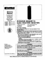
Owners
Manual
FOP, POTABLE WATER
HEATING ONLY
NOT SUITABLE FOP,
SPACE HEATING
NOT FOR USE IN
MOBILE HOMES
Model No.
153.330401
153.330451
153.330501
153.330551
153.330701
153.330751
40
40
50
50
75
75
Gal. High Altitude
Gal.
Gal. High Altitude
Gal.
Gal. High Altitude
Gal
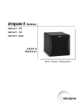
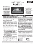
POWER
MISER TM 12
GAS
WATER
HEATER
• Safety Instructions
• Installation
• Care
• Operation
• Parts
and Maintenance
• Troubleshooting
List
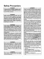
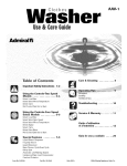
For Your Safety
AN ODORANT
IS ADDED
WATER
HEATER
TO THE
GAS USED
BY THIS
WARNING:
If the information.in
these instructions, are not foil lowed exactly a .fire or explosion may result, causing property
damage, personal mlury or death.
-Do not store or use _. oline or other fl .am.mable vapors and liq. uids in the vicinity of this or any other appliance.
-WHAT TO DO IF YOU SMELL GAS
": Do not try to light any appliance.
Do not touch any electrical switch; do not use any phone in your
building.
.
.
• i Immediately
Follow the gascall
supplier's]nstructions.
your gas suppher from a netghbor's phone.
If you can not reach your gas supplier, call the fire department.
:Installation and service must be performed by a qualified installer,
• service agency or the gas supplier.
Caution:
Read and Follow
All Safety Rules and
Operating instructions
Before First Use of
This Product.
_t,WARNING.
.
Improper installation, adjustment, alteratton, service or m_antenance
can cause DEATH, SERIOUS BODILY INJURY, OR PROPERTY DAMAGE: Refer to this manual for assistance or consult the local Sears
Servtce Center or gas utthty for further reformation.
AWARNING
Flammable vapors may be drawn by air currents from other areas
of the structure to this appliance.
Savethis Manual for Future Reference.
READ THE GENERAL SAF_N
BEGINNING ON iNSIDE
COVER AND THEN THIS ENTIRE
MANUAL BEFORE INSTALLING I
AWARNING
OR OPERATING THIS WATER HEATER.
Sears, Roebuck and Co., Hoffman
Estates, IL 60179 U.S.A.
Safety
Precautions
_WARNING
Improper
installation,
adjustment,
alteration,
service
or maintenance
can cause DEATH,
SERIOUS
BODILY
INJURY, OR PROPERTY
DAMAGE.
Refer to this manual for assistance
or consult your local Sears Service
Center
for further
nformat
_,WARNING
I
At the time of manufacture
this water heater was provided with a combination temperature-pressures
relief valve
certified
by a nationally
recognized
testing laboratory
that maintains periodic inspection of production of listed
equipment
or materials,
as meeting the requirements
for
Relief Valves and Automatic
Gas Shutoff Devices for Hot
Water
Supply Systems, and the latest edition of ANSI
Z21.22 and the code requirements
of ASME. If replaced,
the valve must meet the requirements
of local codes, but
not less than a combination
temperature
and pressure
relief valve certified
as meeting
the requirements
for
Relief Valves and Automatic
Gas Shutoff Devices for Hot
I
on.
_,WARNING
WATER
HEATERS
EQUIPPED
FOR ONE TYPE GAS
ONLY: This water heater is equipped
for one type gas
only. Check the model rating plate near the gas control
valve for the correct gas. DO NOT USE THIS WATER
HEATER WITH
ANY GAS OTHER
THAN
THE ONE
SHOWN
ON THE MODEL
RATING
PLATE. Failure to
use the correct gas can cause problems which can result in
DEATH,
SERIOUS
BODILY
INJURY, OR PROPERTY
DAMAGE.
if you have any questions or doubts consult
your gas supplier or local utility.
Water Supply Systems, ANSI
ognized
testing
laboratory
inspection
of production
materials.
The valve must be marked with a maximum set pressure
not to exceed the marked hydrostatic working pressure
of the water
heater (150 Ibs.lsq. in.) and a discharge
capacity not less than the water
heater input rate as
shown on the model
rating
plate. (Electric
heaters watts divided by 1000 x 3415 equal BTUIHr. rate.)
Your local jurisdictional
authority,
while mandating
the
use of a temperature-pressure
relief valve complying
with ANSI Z21.22 and ASME, may require a valve model
different from the one furnished with the water heater.
AWARNING
INSTALLATIONS IN AREAS WHERE FLAMMABLE LIQUIDS (VAPORS) ARE LIKELY TO RE PRESENT OR
STORED (GARAGES, STORAGE, AND UTILITY AREAS,
ETC): Flammable liquids (such as gasoline, solvents,
propane (LP) or butane, etc.), all of which emit flammable
vapors, may be improperly stored or used in such areas.
The gas water heater pilot light or main burner can ignite
such vapors. The resulting flashback and fire can cause
death or serious burns to anyone in the area, as well as
property damage.
If installation in such areas is your only option, then the
installation must be accomplished in a way that the pilot
flame and main burner flame are elevated from the floor
at least 18 inches. While this may reduce the chances of
flammable vapors from a floor spill being ignited, gasoline
and other flammable substancesshould never be stored or
used in the same room or area containing a gas water
heater or other open flame or spark producing appliance.
NOTE: Flammable vapors may be drawn by air currents
from other areas of the structure to the appliance.
Compliance with such local requirements
must be satisfied by the installer or end user of the water heater with
a locally prescribed
temperature-pressure
relief valve
installed in the designated opening in the water heater in
place of the factory furnished valve.
For safe operation
of the water heater, the relief valve
must not be removed
from it's designated
opening or
plugged.
The temperature-pressure
relief valve must be installed
directly into the fitting of the water heater designated for
the relief valve. Position the va[ve.do_ma_d_dprovide
tubing so that any discharge will exit only within 6_inches
above, or at any distance below_l
fl_or. Be
certain that no contact is made with any I'v_ e_tri_al
......
I
part. The discharge
opening must,jn_b_
blocked or
reduced
in size under a n.y__tanCes.-Excessive
length, over 30 feet, or use of more than four elbows can
cause restriction
amd r_ducQ-the
discharge capacity of
the valve.
No valve or other
_,WARNING
AWARNING
obstruction
is to be placed between
the relief
valve and the tank. Do not connect tubing
directly to discharge drain unless a 6 air gap is provided.
To prevent bodily injury, hazard to life, or property damage, the relief valve must be allowed to discharge water
in quantities
should circumstances
demand. If the discharge pipe is not connected to a drain or other suitable
means, the water flow may cause property damage.
The Discharge Pipe:
Must not be smaller in size than the outlet pipe size of
the valve, or have any reducing couplings
or other
restrictions.
If this water heater will be used in beauty shops, barber
shops, cleaning establishments,
or self-service laundries
with dry cleaning equipment,
it is imperative
that the
water heater or water heaters be installed so that combustion and ventilation
air be taken from outside these
areas.
Refer to the "Facts
to Consider
About
the
Location"
section of this manual and also the latest edition of the National
Fuel Gas Code, ANSI Z223.1, also
referred to as NFPA 54 for specifics provided concerning
air required.
A fire can start if co_ials
cleaning materials, or flammable
or next to the water heater.
Z21.22 by a nationally recthat maintains
periodic
of listed
equipment
or
1
such as clothing, I
liquids are placed against I
I
Must not be plugged or blocked.
Must be of material
listed for hot water distribution.
Must be installed so as to allow complete drainage of
both the temperature-pressure
relief valve, and the discharge pipe.
Must terminate at an adequate drain.
Must not have any valve between the relief valve and
tank.
Safety Precautions
AWARNING
AWARNING
A gas water heater cannot operate properly without the
correct amount of air for combustion. Do not install in a
confined area such a closet, unless you provide air as
shown in the "Facts to Consider About the Location" section. Never obstruct the flow of ventilation air. If you have
any doubts or questions at all, call your gas company.
Failure to provide the proper amount of combustion air
can result in a fire or explosion and can cause DEATH
SERIOUS BODILY INJURY, OR PROPERTY DAMAGE.
This water heater must not be installed directly on carpeting. Carpeting must be protected by a metal or wood
panel beneath the appliance extending beyond the full
width and depth of the appliance by at least 3 inches
(76.2mm) in any direction, or if the appliance is installed
in an alcove or closet, the entire floor must be covered b
the panel. Failure to heed this warning may result in
fire hazard.
AWARNING
AWARNING
VENT DAMPERS - Any vent damper, whether it Is operated thermally or otherwise must be removed if its use
inhibits proper drafting of the water heater.
Thermally Operated Vent Dampers: Gas-fired water
heaters having thermal efficiency in excess of 80% may
)reduce a relatively low flue gas temperature. Such temperatures may not be high enough to properly open thermally operated vent dampers, This would causespillage of
flue gasesand may causecarbon monoxide poisoning.
Vent dampers must bear evidence of certification as complying with the latest edition of American National
tandard ANSI Z21.68 (ANSI Z21.66 & 67, respectively,
cover electrically
and mechanically
actuated vent
dampers). Before installation of any vent damper, consult
your local Sears Service Center or the gas utility for further information.
HOTTER WATER CAN SCALD: Water heaters are
intended to produce hot wuten Water heated to a temperatere which will satisfy clothes washing, dish washing,
and other sanitizing needs can scald and permanently
injure you upon contact. Some people are more likely to
be permanently injured by hot water than others. These
include the elderly, children, the infirm, or physically/mentally handicapped. If anyone using hot water in your home
fits into one of these groups or if there is a local cede or
state law requiring a certain temperature water at the hot
water tap, then you must take special precautions. In addition to usingthe lowest possibletemperature setting that
satisfies your hot water needs, a means such as a mixing
valve, should be used at the hot water taps used by these
people or at the water heater. Mixing valves are available
at plumbing supply or hardware stores. Follow manufacturers instructions for installation of the valves. Before
changing the factory setting on the thermostat, read the
"Temperature Regulation" section in this manual.
AWARNING
• The appliance and its individual shutoff valve must be disconnected from the gas supply piping system during any
pressure testing of the gas system at test pressures in
excessof ½ pound per square inch (3.5kPa).
,The appliance must be isolated from the gas supply piping system by closing Its individual manual shutoff valve
during any pressure testing of the gas supply piping system at test pressures equal or less than _ pound per
square inch (3.SkPa).
AWARNING
Soot build-up indicates a problem that requires correction before further use. Turn "OFF" gas to water heater
and leave "OFF" until repairs are made, because failure
to correct the cause of the sooting can result in a fire or
explosion causing DEATH, SERIOUS BODILY INJURY,
OR PROPERTY DAMAGE.
_,WARNING
AWARNING
Chemical vapor corrosion of the flue and vent system
may occur if air for combustion contains certain chemical
vapors. Spray can propellants, cleaning solvents, refrigerator and air conditioner refrigerants,
swimming pool
chemicals, calcium and sodium chloride, waxes, bleach,
and process chemicals are typical compounds which are
potentially corrosive.
BEFORE LIGHTING
[PROPANE (L.P.) GAS WATER
HEATERS]: Propane (L.R) gas is heavier than air. Should
there be a leak in the system, the gas will settle near the
ground. Basements, crawl spaces, skirted areas under
mobile homes (even when ventilated), closets and areas
below ground level will serve as pockets for the accumulation of this gas. Before attempting to light or relight the
water heater's pilot or turning on a nearby electrical light
switch, be absolutely sure there is no accumulated gas in
the are_ Search for odor of gas by sniffing at ground level
in the vicinity of the appliance. If odor is detected, follow
steps indicated at "For Your Safety" on the cover page of
this manual then leave the premises.
Obstructed or deteriorated vent systems may present a
WARNING
serioushealth Hsk or A
asphyxiation,
Safety Precautions
3
continued on page 4
j
Safety Precautions
AWARNING
I
The water heater with droft hood Installed must be prop- I
erty vented to a chimney which terminates outdoors.
Never operate the water heater unlessit is vented to the
outdoors and has adequate air supply to avoid risks of I
mpmper operation, expos on or asphyxiation,
I
AWARNING
Minimum clearances between the wafer he_tor and combustible construction are I" at the sidesand rear, 4" at the
front, and 6" from,the vent pipe. Clearance from the top
of the jacket is 18 on most models. Note that a lesser
dimension may be allowed on some models. Refer to the
label on the water heater adjacent to the gas control valve
for all clearances.
AWARNING
Do not use this appliance if any part of it has been under J
water. Immediately call a Sears Service Technician to I
inspect the appliance and to replace the gas control or any
part of the burner system which has been under water.
_,WARNING
HYDROGEN GAS: Hydrogen gas can be produced in a hot
water system that has not been used for a long period of
time {generally two weeks or more). Hydrogen gas is
extremely flammable and explosive. To prevent the possibility of injury under these conditions, we recommend the
hot water faucet be opened for several minutes at the
kitchen sink before any electrical appliances which are
connected to the hot water system are used (such as a dishwasher or washing machine). If hydrogen gas is present,
there will probably be an unusual sound similar to air
escaping through the pipe as the hot water faucet is
opened, There must be no smoking or open flame near
the faucet at the time it is open.
AWARNING
INSULATING
JACKETS: When installing an external
water heater insulation jeckat on a gas water heator:
• DO NOT cover the temperaturn-pressure
relief valve.
• DO NOT put insulation over any part of the top of the
gaswater heater.
• DO NOT pat insulation over the gas control valve or gas
control vaive/burner cover, or any access areas to the
burner.
• DO NOT let insulation around the gas water heater to
get within 8 inches of the floor {air must get to the
burner).
• DO NOT cover or remove operating instructions, and
safety related warning labels and materials affixed to the
water heater.
Failure to heed this will result in the possibility of a fire or
explosion.
ACAUTION
WATER HEATERS EVENTUALLY LEAK: Installation of
the water bea_.er must be accompl_-d
in such a manner
that if the tank or any connections shouldleak, the flow of
water will not cause damage to the structure. When such
locations cannot be avoided, a suitable drain pan should
be installed under the water heater. Drain pans are available at your local Sears store. Such a drain pan must be
not greater than I _ inches deep, have a minimum length
and width of at least 2 Inches greater than the water
heater dimensions and must be piped to an adequate
drain. The pan must not restrict combustion air flow.
Under no circumstances is the manufacturer or Sears to
be held liable for any water damage in connection with
this water heater.
Table of Contents
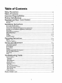
Safety Precautions .....................................................................................................
_-4
Table of Contents ............................................................................................................
5
Customer Responsibilities .............................................................................................
6
Product Specincations
"_
....................................................................................................
6
Materials and Basic Tools Needed ...............................................................................
Materials Needed .....................................................................................................................................................................
Basic Tools ...............................................................................................................................................................................
Installation Instructions .................................................................................................
8-16
Removing the Old Water Heater ...............................................................................................................................................
8
Facts to Consider About the Location .......................................................................................................................................
9
Combustion Air and Ventilation for Appliances in Unconfined Spaces ...................................................................................
10
Combustion Air and Ventilation for Appliances in Confined Spaces .......................................................................................
10
Water Piping .............................................................................................................................................
:............................. 11
Temp_lture-Pressure
Relief Valve....... ....................................................................................................................................
12
Filling th_ Water Hater ..........................................................................................................................................................
13
Venting ..............................................................................................................................................................................
13-14
Gas Piping .........................................................................................................................................................................
14-15
Installation Checklist ..............................................................................................................................................................
16
Operating Instructions ...................................................................................................
17-19
Eighting .............................................................................................................................................................................
Temperature Regulation ..........................................................................................................................................................
17-18
19
Service and Adjustment .................................................................................................
20-22
Tank (Sediman0 Cleaning ......................................................................................................................................................
Vendng System Impe_ion ......................................................................................................................................................
Burner Inslx"edon ...................................................................................................................................................................
Burner Clewing .....................................................................................................................................................................
Draining .................................................................................................................................................................................
Temperatu_Pr_,_e
ll_ief Val_ Operation ..........................................................................................................................
Drain Valve Washer Reph_etu
...........................................................................................................................................
Housekeeping .........................................................................................................................................................................
Service ....................................................................................................................................................................................
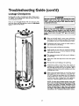
Troubleshooting
Guide ..................................................................................................
22-25
Start lip Conditiom ...............................................................................................................................................................
Condensation .......................................................................................................................................................................
Smoke/Odor .........................................................................................................................................................................
Thermal Expansion .........................................................................................................................................................
Strange Sounds .....................................................................................................................................................................
Operational Conditions .....................................................................................................................................................
Smelly Water .........................................................................................................................................................................
"Air" in Hot Water Faucets ...................................................................................................................................................
High Temperature Shut Off System ......................................................................................................................................
Not Enough Hot Water ........................................................................................................................................................
Water is mo Hot ...................................................................................................................................................................
Leakage Checkpoints
20
20
20
20
21
21
21
21
21
..............................................................................................................................................................
22
22
22
22-23
23
23-24
23
23
24
24
24
25
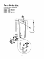
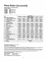
Parts Order List ......................................................................................................................
26-27
5
Customer
Responsibilities
Thank You for purchasing
This gas-fired water heater is design certified by the
International Approval Services, A Division of CSA under
American National Standard/CSA Standard for Gas Water
Heaters AN$ Z21.10.1 • CSA 4.1 (latest edition). The
installation must conform with this manual, Local Codes
and with the latest edition of the National Fuel Gas Code,
ANSI Z223.1.
This publication is available from your local government or
public library, gas company, or by writing NFPA,
Batterymavch Park, Quincy, MA 02269.
• This manual contains instructionsfor the installation, operation, and maintenance of the gas-firedwater heater. It also
contains warnings through out the manualthat you must read
and be awareof. All warningsand all instructionsare essential
to the proper operation of the water heater and your safety.
Since we cannot put everything on the first few pages, READ
THE ENTIRE MANUAL BEFORE ATTEMPTING TO
INSTALL OR OPERATE THE WATER HEATER.
• The installationmust conform with the instructions in this
manual; _as company rules; and Local Codes, or in the
absenceorLocal Codes, with the latestedition of the National
Fuel Gas code, ANSI Z223.1, also referredto as NFPA 54.
This publication is available from your local governmentor
public library or gas company or by writing NFPA,
Batterymarch Park, Quincy,MA 02269.
• If after reading this manual you have any questions or do not
understand any portion of the instructions, call the Sears
ServiceCenter.
• Carefully plan the place where you are going to put the water
heater. Correct combustion, vent action, and vent pipe installation are very important in preventing death from possible
carbon monoxide poisoning and fires.
F.xaminethe location to ensure the water heater complieswith
the "Facts to Consider about the Location" section in this
• Read the "Safety Precautions"section, pages 2 through 4 of
this manual first and then the entire manual carefully.If you
don't follow the safety rules,the water heater will not operate
properly. It could cause DEATH, SERIOUS BODILY
INJURY AND/OR PROPERTYDAMAGE.
• For California installation this water heater must be braced,
anchored, or strapped to avoid failing or moving during an
earthquake. See instructions for correct installation procedures. Instructions may be obtained from your local dealer,
wholesaler, public utilities or California Office of the State
Architect, 400 P Street, Sacramento, CA 95814.
a Sears water heater.
Properly installed and maintained, it should give you years of
trouble free service. If you should decide that you want the new
water heater professionally installed by Sears call the local Sears
Service Center or any Searsstore. They will arrange for prompt,
quality installation by Searsauthorized contractors.
Abbreviations Found In This Instruction Manual
I.A.S. - International Approval Services,A Division of CSA
A.N.S.L -American National Standards Institute
N.F.EA.- National FireProtection Agency
AWARNING
manual.
Product Specifications
MODEL
NUMBER
DIMENSIONS
TANK
CAPACITY
IN GALLONS
TYPE
OF
GAS
153.330401
40
NATURAL
40,000
46.0
153.330451
40
NATURAL
40,000
46.0
153.330501
50
NATURAL
40,000
46.0
153.330551
50
NATURAL
40,000
46.0
3" or4"
3" or 4"
3" or 4"
3" or 4"
153.330701
75
NATURAL
55,000
59.2
153.330751
75
NATURAL
55,000
59.2
B.T.U.
RATE
RECOVERYRATE
GALS. PER HOUR
@90"F RISE
MINIMUM
VENT
PIPE
DIAMETER
IN INCHES
HEIGHTTO
_ACKETTOP
18"
60"
18"
"60"
20"
59½"
4"
20"
24"
59½"
60"
4"
24"
60"
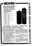
Materials
Materials
and Basic Tools Needed
Needed
To simplify the installation Sears has available the installation
parts shown below. You may or may not need all of tbese materials, depending on your type of installation.
o
VENT
WATER
HEATER STAND 24"x24"xl 8"
FOR USE WITH
WATER
HEATERS
INSTALLED
IN RESIDENTIAL
GARAGES
HAVING
A DIAMETER
24"
OR LESS AND A RATED CAPACITY
75
GALLONS
OR LESS
ELBOW
FLEXIBLE WATER
HEATER GAS CONNECTOR
WITH
FITrlNGS
EXPANSION
TANKS
FOR THERMAL
EXPANSION
CONDITIONS
AVAILABLE
IN
2 GALLON
AND 5
GALLON
CAPACITY
THROUGH
LOCAL
BEARS STORE OR
SERVICE CENTERS
WATER HEATER
INSTALLATION
KIT WITH
FLEXIBLE CONNECTORS
FOR
3/4" OR 112" THREADED
OR COPPER PLUMBING
DRAIN
PANS
AVAILABLE
IN 20" DIAMETER
FOR
WATER HEATERS
HAVING
A DIAMEVENT
WATER
HEATER HEAT
TRAPS HELP REDUCE
HEAT
LOSS DUE TO THERMAL
SYPHONING
PIPE
TER 18" OR LESS AND AVAILABLE
IN
28" DIAMETER
FOR WATER HEATERS
HAVING
A DIAMETER
26" OR LESS
Basic Tools
ADDITIONAL
TOOLS NEEDED
WHEN SWEAT SOLDERING
You may or may not need all of these tools, depending on your
type of installation. These tools can be purchased at your local
Sears store.
•
•
•
•
•
•
• Pipe Wrenches (2) 14"
• Screwdriver
• Tin Snips
• 6 Foot Tape of Folding Rule
• Garden Hose
• Drill
• Pipe dope or Teflon Tape
Tubing Cutters or Hacksaw
Propane Torch
Soft Solder
Solder Flux
Emery Cloth
Wire Brushes
\
]
HACKSAW
GARDEN
HOSE
6 FOOT
TAPE
314" WIRE
PIPE
WRENCH
SLOT-HEAD
SCREWDRIVER
112" WIRE
PHILLIPS
BRUSH
BRUSH
SCREWDRIVER
TIN
PROPANE
TORCH
SNIPS
ROLL OF LEAD FREE
SOFT SOLDER
B
ROLL OF TEFLON
TAPE
(USE ONLY ON WATER
CONNECTIONS)
PIPE DOPE (SQUEEZE
TUBE)
USE FOR WATER
AND
_
CONNECTIONS)
DRILL
ROLL
7
OF EMERY
CLOTH
SOLDER
FLUX
TUBING
CUTTER
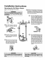
Installation
Removing
QTurn
l
Instructions
the Old Water
Heater
_OFF" the gassupply to the water heater.
I
AWARNING
[f the main gas line--all
gas appliances is I
used, also shut "OFF" the gas at each appliance. Leave all I
gas appliances shut "OFF" until the water heater Installatlon iscomplete,
I
ODisconnect
the vent pipe from the draft hood where
they connect to the water heater. In most installations
the vent pipe can be lifted off after ally screw or other
attached devices are removed. Dispose of the draft
hood. The new water heater has the draft hood which
must be used for proper operation.
Q
a. If you have copper piping to the water
heater, the two copper water pipes can
be cut with a hacksaw approximately 4"
away from where they connect to the
water heater. This will avoid cutting off
the pipes too short. Additional cuts can
he made later if necessary. Disconnect
the temperature-pressure relief valve
drain line. When the water heater is
drained, disconnect the hose from the
drain valve. Close the drain valve. The
water heater is now completely disconnected and readyto be removed.
Q
b. If you have galvanizedpipe to the water
heater, loosen the two galvanizedpipes
with a pipe wrench at the union in each
line. Also disconnect the piping remaining to the water heater. These pieces
should be saved since they may be needed when reconnecting the new water
heater. Disconnect the teraperamre-pressure relief valve drain line. When the
water heater is drained, disconnect the
hose from the drain valve. Close the
drain valve. The water heater is now
completely disconnected and ready to be
the water to the water
QTurn
heater. Some installations require that
the water be turned off to the entire
UOFF_
house.
®
QChack
a_ain to 1_n_e sure the gas supply
is _OFF to the water heater Then disconnect the gas supply connection from
the gas control valve.
G
Attach a hose to the water heater drain
valve and put the other end in a floor
drainor outdoors.Open the waterheater
drain valve. Open a nearby hot water
faucet which will relievepressure in the
water heater and speed draining.
AWARNING
The water passingout ofthe drainvalvemay beextremely
hot. To avoidbeing scalded,make sureall connectionsare
tight and that the water flow is directed away from any
person°
rerfloved.
ACAUTION
Mineralbuildupor sedimentmay haveaccumulatedin the
oldwater heater.This causesthe water heater to be much
heavierthan normal and this residue,if spilledout, could
causestaining.
Installation
Instructions
Facts to Consider
Location
About
the
You should carefully choose an indoor location for the new
water heater, because the placement is a very important consideration for the safety of the occupants in the building and for
the most economical use of the appliance. This water heater is
not for use in mobile homes or outdoor installation.
Whether replacing an old water heater or putting the water
heater in a new location, the following critical points must be
observed.
•
(cont'd)
The location selected should be indoors as close as practical
to the gas vent or chimney to which the water heater vent is
going to be connected, and as centralized with the water piping system as possible. The water heater, as all water heaters,
will eventually
leak. Do not install without adequate
drainage provisions where water flow will cause damage.
A CAUTION
WATER HEATERS EVENTUALLY LEAK: Installation of the
water heater must be accomplishedin such a manner that if
the tank or any connectionsshouldleak, the flow of water will
not causedamage to the structure. When such locationscannot be avoided,a suitable drain pan shouldbe installed under
the water heater. Drain pans are availableat your local Sears
store. Such a drain pan must be not greater than 1½ inches
deep, have a minimum length and width of at least 2 inches
greater than the water heater dimensionsand must be piped
to an adequatedrain. The panmust not restrict combustionair
Eow.Under no circumstancesis the manufacturer or Searsto
be held liable for any water damage in connection with this
water heater.
AWARNING
INSTALLATIONS IN AREAS WHERE FLAMMABLE UQUIDS :
(VAPORS) ARE LIKELY TO BE PRESENT OR STORED
(GARAGES, STORAGE, AND UTILITY AREAS, ETC):
Flammable liquids(suchas gasoline,solvents,propane (LIP) or
butane, etc.), all of which emit flammable vapors, may be
i_
stered or esed in sudl area_ The ges water heater
pilot light or main burner can ignitesuchveper_ The resulting
flashbackand fire can causedeath or seriousburnsto anyonein
the asea,aswell as prepertydamage.
If installationin suchareas isyour onlyoption, then the instailation must be accomplishedin a way that the pilot flame and
main bumer flame are elevetedfrom tbe floor at least 18 inches.
While this may reducethe chancesof flammablevaporsfrom a
floor spillbeing ignited, gasolineandother flammablesubstances
shouldneverbe storedor used in the same room or area containinga gaswater heater or other open game or sparkproducingappliance.
NOTE: Flammable vaporsmay be drawn by air currents from
other areasof the structureto the appliance.
_,WARNING
Propellants of aerosol spraysand volatile compounds,(deaners,chlorine based chemicals,refrigerants, etc.) in addition to
being highlyflammable in many cases,will also change to corrosive hydrochloric acid when exposed to the combustion
products of the water heater. The results can be hazardous
and also causeproduct failure.
• The location selection must provide adequate dearances for servicing and proper operation of the waterbeater.
*t WARNING
This water heater must not be installeddirectly on carpeting.
Carpeting must he protected by a metal or wood panel
beneath the appliance extending beyond the fulL.width and
depth of the appliance by at least 3 inches(76.2mm) in any
direction, or if the appliance is installedin an alcoveor closet,
the entire floor must be coveredby the panel. Failureto heed
this warningmay resuRin a fire hazard.
AWARNING
Minimum clearances between the water heater and combustible construction are I" at the sidesand rear, 4" at the
front, and 6"from the vent pipe.Clearancefrom the top of the
jacket is 18"on most model_ Note that a lesserdimensionmay
be allowed on some models. Refer to the label on the water
heater adjacentto the gascontrolvalvefor all dearances.
FRONT
VIEW'oF
DOOR
_11
[Pi,u I,
_,N
ARoo
AWARNING
Ages water beater cannot ope_te properly without the co_
rect amount of air for combustion.Do not install in a confined
area such a closet,unlessyou provideair as shown in the "Facts
to Consider about the Location" suedon" Never obstruct the
flow of ventilation air. If youhaveanydoubtsor questionsat all,
callyour gascompany.Failureto providethe proper amount of
combustion air can result in a Ere or explosionand can cause
DEATH, SERIOUS BODILYINJURn,OR PROPERTY DAMAGE,
&WARNING
If this water heater will be usedin beauty shops,barber shops,
cleaning establishments, or self-service laundries with dry
deaning equipment, it is imperative that the water heater or
water heaters be installedso that combustionand ventilation
air be taken from outside these areas. Refer to the "Facts to
ConsiderAbout the Location" section of this manual and also
the latest edition of the National Fuel Gas Code, ANSI 2:223.1
also referred to as NFPA 54 for specificsprovided concerning
air required.
Installation
Instructions
(cont'd)
Combustion Air and Ventilation
for Appliances Located in
Unconfined Spaces
Unconfined Space is a space whose volume is not less than 50
cubic feet per 1,000 Btu per hour of the aggregate input rating
of all appliances installed in that space. Rooms communicating
directly with the space in which the appliances are installed,
through openings not furnished with doors, are considered a
part of the unconfined space
In unconfined spaces in buildings, infiltration may be adequate
to provide _r for combustion, ventilation and dilution of flue
gases. Howler, in buildings of tight construction (for example,
weather stripping, heavily insulated, caulked, vapor barrier, etc.),
additional air may need to be provided using the methods
described in Combustion Air and Ventilation for Appliances
Locatedia Confined Spaces,h.
1. Wt_en directly communicating with the outdoors,each opening shall have a minimum free areaof 1 square inch per 4,000
BTU per hour of total input rating of all equipment in the
enclosure. (See Figure 3.)
2. When communicating with the outdoors through vertical
ducts, each opening shall have a minimum free area of 1
square inch per 4,000 BTU per hour of total input rating of
all equipment in the enclosure.(See Figure4.)
OHI_E¥
_
VE_T_
Ot_
VENT
LC¢_
Combustion Air and Ventilation
for Appliances Located in
Confined Spaces
Confined Space is a space whose volume is less than 50 cubic
feet per 1,000 Btu per hour of the aggregate input rating of all
appliances installed in that space.
a. ALL AIR FROM INSIDE BUILDINGS:
(See Page 9 Figure 1, and Figure 2 below)
The confined space shall be provided with two permanent
openings communicating directly with an additional room(s)
oF sutTlcient volume so that the combined volume of all
spaces meets the criteria for an unconfined space. The total
input of all gas utilization equipment installed in the combined space shall be considered in making this determination.
Each opening shall have a minimum free area of one square
inch per 1,000 BTU per hour of the total input rating of all
gas utilization equipment in the confined space, but not less
than 100 square inches. One opening shall commence within
12" of the top and one commencing within 12 of the bottom of the enclosure.
3. When communicating with the outdoors through horizontal
ducts, each opening shall have a minimum free area of 1
_uare inch per 2,000 BTU per hour of total input rating of
equipment in the enclosure. (See Figure 5.)
Figure S ]
[Fi --21
4. When ducts are used, they shall be of the same cross-sectional
area as the free area of the openings to which they connect.
The minimum short side dimension of rectangular air ducts
shall not be less than 3 ". (See Figure 5.)
b. ALL AIR FROM OUTDOORS: (see Figures3-5)
The confined space shall be provided with two permanent
openings, one commencing within 12 of the top and one
commencing w'th'n 12' from the bottom of the enclosure.
The openings shall communicate directly,or by ducts, with
the outdoors or spaces (crawl or attic) that fredy communicate with the outdoors.
5. Louvers and Grilles: In calculating free area, consideration
shall be given to the blocking effect of louvers, grilles or
screens_rorecting openings. Screens used shall not be smaller
than ¼ mesh. If the free area through a design of louveror
grille is known, it should be used in calculating the size opening requiredto provide the fro: area specified. If the design
and free area is not known, it may be assumed that wood louvers will be 20-25 percent free area and metal louvers and
grilles will have 60-75 percent free area. Louversand grilles
shall be fixed in the open position or interlocked with the
equipment so that they are opened automatically during
equipment operation,
Figure 3 ]
lO
6. Special Conditions Created by Mechanical Exhausting or
Fireplaces:Operation of exhaust fans, ventilation systems,
clothes dryers or fireplaces may create conditions requiring
special attention to avoid unsatisfactory operationof installed
gas utilization equipment.
Installation
Water
Instructions
(cont'd)
Piping
AWARNING
HOTTERWATERCAN SCALD:.Waterheatersareintended
to
producehot vr&ter.
Wator heotedto a tomperatum whichwill
satisfy_
washing,
dishwashing,
andothersani_ng needs
canscaldandpennanen_injureyouuponcontact.SomepeoplearumoR likelyto bepermanently
injuRdbyhot watorthan
others,Theseinclude
theelderly,
children,
theinfirm,or physically/mentally
handicapped.
If anyone
usinghotwaterin yourhome
fitsintooneofthesegruups
or ifthereisa localcodeor statelaw
requiring
a certaintemperature
waterat thehotwatertap,then
youmusttakespecial
precautions.
Inadd'_ion
to usingthelowest
possible
temperaturesettingthatsatisfies
yourhot waterneeds,
a meanssuchasa mixingvalve,should
beusedat tbehotwater
tapsusudb/these peopleor at thewoterheator.Mixingvalves
areavailable
at plumbingsupply
or hardware
store_Followmanufacturursinstructions
for installationof the valves.Before
changingthe factory settingon the thermostat, read the
'q'emperature
Regulation"
section
inthismanual.
This water heater shall not be connected to any heating systemsor
component(s) used with a non-potable water heating appliance.
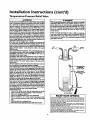
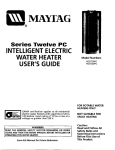
• Look at the top cover of the water heater. The cold water
inlet is markedcold. Put two or three turns of teflon tape
around the threaded end of the threaded-to-sweat coupling
and around both ends of the ¾ threaded nipple. Using flexible connectors, connect the cold water pipe to the coldwater
inlet of the waterheater.
NOTE: This water heater is super insulated to minimize
heat loss from the tank. Further reduction in heat loss
can be accomplished by insulating the hot water lines
from the water heater.
INSTALLATION COMPLETED USING
SEARS INSTALLATION KIT
FLEXIBLE
WATER
CONNECTORS
HOT OUTLET
TO HOUSE
COLD
INLET
WATER
LINE
/
If a water heater is installed in a closed water supply system;
such as one having a back-flow preventer, check valve, water
meter with a check valve, etc.., in the cold water supply; means
shall be provided to control thermal expansion. Contact the
local utility or local Sears Service Center on how to control this
situation.
THREADED
TO
SWEAT COUPLING
NOTE: To protect against untimely corrosion of hot and
cold water fittings, it is strongly recommended that all-electric unions or couplings be installed on this water heater
when connected to copper pipe.
314" THREADED
HEAT TRAP WITH
SECONDARY
ANODE
THREADED
TO
SWEAT COUPLING
--
314" THREADED
H EAT TRAP
The illustration shows the attachment of the water piping to the
water heater. The water heater is equipped with _" water connections.
NOTE: If using copper tubing, solder tubing to an adapter
before attaching the adapter to the cold water inlet connection. Do not solder the cold water supply line directly to the
cold water inlet. It will harm the dip tube and damage the
tank.
•
PRESSURE
RELIEF VALVE
Look at the top cover of the water heater. The water outlet is
marked hot. Put two or three turns of teflon tape around the
threaded end of the threaded-to-sweat coupling and around
both ends of the 3A"threaded nipple. Using flexible connectors, connect the hot water pipe to the hot water outlet on
the water heater.
PIPE (Do not
or plug)
FLOOR
DRAIN
Installation
Instructions
Temperature-Pressure
(cont'd)
Relief Valve
AWARNING
A, WARNING
At the time of manufacture this water heater was provided
with a combinationtomperature-pressures relief valve certified
by a nationally recognizedtesting laboratory that maintains
periodic inspectionof productionof listed equipment or materials, as meeting the requirements for Relief Valves and
Automatic Gas Shutoff Devicesfor Hut Water SupplySystems,
and the latest edition of ANSI Z2h22 and the code require.
ments of ASME. If replaced, the valve must meet the ,_luire ments of localcodes,but not lessthan a combinationtemperature and pressurerelief valve certified as meeting the Rquirements for Relief Valvesand Automatic Gas ShutoffDevicesfor
Hot Water SupplySystems,ANSI Z21.22 by a nationallyrecognized testing laboratory that maintains periodic inspectionof
productionof listedequipment or materials.
The valve must be marked with a maximum set pressurenut
to exceed the marked hydrostatic working pressure of the
water heater (150 IbsJsq.in.) and a dischargecapacitynot less
than the water heater input rate as shownon the model rating
plate. (Electric heaters, watts divided by 1000 x 3415 equal
BTU/Hr. rate.)
Yourlocal jurisdictionalauthority,while mandatingthe use of a
temperature-pressure relief valve complyingwith ANSI 7.21.22
and ASME, may require a valve model different from the one
furnishedwith the water heater.
Compliancewith such localrequirements must be satisfiedby
the installeror end user efthe water heater with a locallyprescribed temperaCure-pressurerelief vaive installedin the designatod opening in the water heater in place of the factory foruishodvalve.
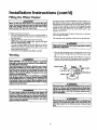
For safe operationof the water heater,the relief valve must nut
be removed from it'sdesignatedopeningor plugged.
The temperatuure-pressurerelief valve must be Installeddirectly
inte the fittingofthe water heater designatedfor the relief valve.
Positionthe valve downwardand providetubingso that any dischargewill exit onlywithin 6 inchesabove, or at any distance
below the structural floor Be certain that no contact is made
with _ny live e|ectricalpa_ Tbe dlsch_rgeopeningmust net be
blockedor reduced in size under any circumstances.Excessive
length,over 30 feet, or useof more than four elbowscan cause
restriction and reduce the dischargecapacityofthe valve.
No vuiveer other obsttuctlneis tu be pincodbetweenthe rafief
valve andthe tank. Do not connecttubing directlyto discharge
drain unlessa 6"air gapisprovided.Topreventbodilyinjury,hazard to life,or propertydamage,the relief valve must be allowed
to dischargewater in quantitiesshould drcumstancesdemand, if
the dischargepipeis not connectedto a drain or other suitable
means,the water flow may causepropertydamage.
The DischargePipe:
Must nut be smaller in size than the outlet pipe size of the
valve,or haveany reducingcoupiings or other restrictions.
Must nut be pluggedor b|ocked.
Must be of material listed for hot water distribution.
Must be instaJlodso as to allow complete drainageof both
the temperature.prossure relief valve, and the discharge
pipe.
Mustterminate at an adequatedrain.
Must not haveany valvebetween the relief valveand tank.
The temperaturo-prossuro relief valve must be manually
operated at least once a year. Caution should be taken to
ensuro that (I) nu one is in front of or around the outfet of
the tempe_aturo-pressurerelief valve dischargeline, and (2)
the water manually discharged will not cause any bodily
injury or property damage because the water may be
extrerne_ ho_
If after manually operating the valve, it fails to completely
reset and continuesto release water, immediately closethe
cold water inlet to the water heater, follow the draining
instructions, and replace the temperature-pressure relief
vuivewith a new one.
COLD
HOT
_4
SHUT OFF
VALVE
PRESSURE
RELIEF VALVE
:cap
FLOOR
DRAIN
1
"AP
RELIEFVALVE OPENING
At the time of manufacoure,
this water heaterwas providedwith a combinationter_
pe_ture-pressurerelief valvelistedas complying with the standardfor relief val_s
and automatic gasshot-off d_ces for hot wa_r supplysystems,ANSI Z21.22. For
safeoperationof the water heater,the relief valvemust not be removed from its dasignitedpointof installation or plugged.
Your localjurisdictionalauthority,whilemandatingthe use of a temperawre-pressure
rebef_dve complyingwith ANSI Z21.22 andASHE may require a valve model different from the onefurnishedwith _e water hea_
Compliancewith suchlocalP_quiremen_musebe satisfied bythe installeror end user
of r_e wz_er heater with a locallyprescribed temperature-pressure relief valve
installedin the designatedopening_nthe water beate_
Seemanualhe_ding-'remperatur_P_ssure Kelief Valve" for installationand main_narge of relief valve,dischargeline,and other _fety precautions.
12
Installation
Filling the Water
Instructions
(cont'd)
Heater
For proper venting in certain installations, a largerdiametervent
pipe may be necessary. Due to great variancesin installations,
unforeseeable by the manufacturerof the waterheater, you must
consult your gascompany to aid you in determiningthe proper
venting for your water heater from the vent tables in the latest
edition of the National Fuel Gas Code ANSI Z223.1, also
referredto as NFPA 54.
A CAUTION
I
Never use thiswater heater unlessit is completely filled with [
water. To prevont damageto the tank, the tank must be filled I
with water. Water must flow from the hot water faucet
beforeturning ON" gasto tile water heater.
To fill the water heater with water:
• Close the water heater drain valve by turning the handle to
the right (clockwise).The drain valveis on the lowerfront of
the water heater.
• Open the cold water supply valveto the water heater.
NOTE: The cold water supply valve must be left open
when the water heater is in use.
• To insure complete filling of the tank, allow air to exit by
opening the nearest hot water faucet. Allow water to run
until a constant flow is obtained. This will let air out of the
water heater and the piping.
• Check all new water piping for leaks.Repairas needed.
Check the venting system for signs of obstruction or deterioration and replaceif needed.
The combustion and ventilationair flowmust not be obstructed.
AWARNING
Obstructed
er detederatedventsystems
maypmseata serious
healthriskor asphyxiatio_
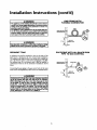
• Place the drafthood legs in the receiving holes on the top of
the water heater. The legswill snap in the holes to give a tight
fit.
• Place the vent pipe over the drafthood. With the vent pipe in
position, drill a small hole through both the vent pipe and
drafthood. Secure them together with a sheet metal screw.
Venting
AWARNING
VENT DAMPERS.Any vent damper,whetherit isoperated
thermallyer otherwisemustbe removed
if itsuseinhibitsproper drefdngoftbewa_erheater.
ThermallyOper_ed Vent Damper_Gas-firedwater heaters
havingthermalefficiency
in excessof80%mayproducea mlat_ely lowfluegastemperature.Suchtemperatures
mar/not be
high enoughto properly open thermally operated vent
dampers.Thiswouldcausespillage
of Iluegases
andmaycause
carbonmonocle poisoning.
Ventdampersmustbearevidence
of certification
ascompiying
with the latesteditionof AmericanNationalStandardANSI
Z21.68(ANSI 7.21.66& 67, mspec6vely,
coverelectrically
mechanically
actuatedventdampers).Beforeimtall_on of am/
ventdamper,comuityourlocalSearsServiceCenteror tbeges
DRAFT
HOOD
,_%__ _
IVENT'_
I
_
f,I__,FT
HOOD
VENT
DRAFT
utility for further information.
I'_
H( _OD
TO OUTDOORS
OR
CHIMNEY
AWARNING
Thewaterheaterv th hd
]
mustbe proper l
ventedto a chimneywhkh termieatesoutdoors,Neveropec-I
ate thewaterheaterunless
it isventedte the outdeors
and hasI
adequate air_
to avoidrisksof hnproperoperation,explo-]
AWARNING
To insure proper venting of this gas-fired water heater, the
correct vent pipe diameter must be utilized. Any additionsor
deletions of other gasapplianceson a common vent with this
water heater may advarselya_rectthe operation of the water
heater. Consult the localSears Service Center or gas utility if
any suchchangesam planned.
er
I
J
AWARNING
Tbeventpipefromthrust
l
be no _s than theI
diameter of the draft hood outlet on the water heater, and|
slope upward to the chimney at least ¼inch per linear]
13
Installation
Instructions
(cont'd)
Gas Piping
Venting (cont'd)
All vent gases must be completely vented to the outdoors of the
structure (dwelling). Instalfonly the draft hood provided with
the new water heater and no other draft hood.
Vent pipes must be secured at each joint with sheet metal screws.
AWARNING
Make surethe gassuppliedisthe same type listedon the
model ra_ng plate. The inlet r,.s pressure mint net exceed
10.Sin.watercolumn(?.6kPa)for naturalgasor 13in.water
column(3.2kPa)for prepane(L.P.)gas. The minimuminlet
gaspressurelistedon the modelratingplate isfor tile purposeofinput aff_aement.
CHIMNEY
I
TO
&WARNING
|
If the gas control vaJveIs subjectedto pressuresexceeding 'AI
I ix_nd per square Irw.h(3.SkPa), the damase to the gascon- I
[ m)l valve eonldresult in a fire or explosionfrom leakinggas. [
VENT PIPE INSTALLATION
There must be a minimum of 6" clearance between single wall
vent pipe and any combustible material. Fill and seal any clearance "between single wall vent pipe and combustible material
with mortar mix, cement, or other fioncombustible substance.
For other than single wall, follow vent pipe manufacturer's clearance specifications. To insure a tight fit of the vent pipe in a
brick chimney, seal around the vent pipe with mortar mix
cement.
AWARNING
I
If the main gaslinethutoff servingall gasappliances
is used,
alsotom "OFF" the gasat eachappliance.Leaveall gasappli[ancesshutoffund the water heaterinstalat;oniscomplete. I
A gas line of sufficient size must be run to the water heater.
Consult the latest edition of National Fuel Gas Code ANSI
Z223.1, also referred to as NFPA54 and the gas company concerning pipe size.
&WARNING
Failure to have required dearances between vent piping and
combustible material will result in a fire hazard.
Aw m,NG
There must be:
• A readily accessible manual shut off valve in the gas supply line
serving the water heater, and
• A drip leg (sediment trap) ahead of the gas control valve to hdp
prevent dirt and foreign materials from entering the gas control
I
Be sure vent pipe is properly connected to prevent escape of I
,uepses
€ ,Id
deed
Valve,
]
• A flexible gas connector or a ground joint union between the
ahutoffvalve and control valve to permit servicing of the unit.
Be sure to check all the gas piping for leaks beforeli_,hdng the
water heater. Use a soapy water solution, not a match or open
flame. Rinseoff soapy solution _d wipe dry.
AWARNING
Chemical vapor corrosion of the flue and vent system may
occur if air for combustion containscertain chemicalvapors.
Spray can propellants, deaning solvents,refrigerator and air
conditionor refrigerants, _'wimming pool chemicals, calcium
and sodium chloride, waxes, bleach,taxi process chemicaJsare
typicalcompoundswhichare potentiallycorrosive.
Standard Models are for instaUadon up to 3,300 feet above sea
level.
High Altitude Models are for ir_stalLationfrom 3,300 to 5,500
feetabovesea level.
Ifa standard model is installedabove 3,300 feet or a high aldtude
model is installed above 5,500 feet, the input rating must be
reduced at the rate of 4 percent for each 1,000 feet above sea level.
Contact your local SearsService Center or gas utility for further
information.
AWARNING
The appliance and its gasconnectionmust be leak tested
beforeplacingthe app ance noper_on.
14
Installation
Instructions
(cont'd)
GAS PIPING WITH
FLEXIBLE
CONNECTOR
AWARNING
. The appiianceand its individualshutoffvalve must be distortnected from the gas supplypipingsystem duringany pressure
testing of the gas system at test pressuresin excess of
LOOP
, poundper squareinch03kPa).
The q=piiancemust be Isulatedfrom the gassuppiypipingsystern by dosing its individualmanual shutoff raise during any
pre_um testingof the gassupplypiping systemat test pressuresequal or lessthan ½ poundper squareinch(3.51d:a).
GAS
3ONTROL
VALVE
GROUND
DRIP LEG
(Sediment
AWARNING
Use pipejoint compoundor teflon tape marked as being
resistantto the actionof petroleum[Propane(I.R)] gase_
SEDIMENT
TRAP
trap)
GAS PIPING WITH
ALL BLACK
PIPE TO GAS CONTROL
A sediment trap shall be installed as dose to the inlet of the
water heater as practical at the time of water heater installation.
The sediment trap shall be either a tee fitting with a capped nipple in the bottom oudet or other device recognized as an effective sediment trap. Ifa tee fitting is used, it shall be installed in
conformance with one of the methods of installation shown
below.
GROUND
JOINT
UNION(OpUo_I)
"_-"
BLACK PIPE
_
GAS
Connecting the gas piping to the gas control valve of the water
heater can be accomplished by either of the two methods shown.
AWARNING
_-J
Contaminants in the gas linesmay causeimproper operation
of the ps €ontrol valve that may result in tim or explosion.
Before attachingthe gas line be sum that all gas pipe is dean
on the inside.To trap any dirt or foreign material in the gas
supply line, a drip leg (sometimes called a sediment trap)
must be incorporated in the piping. The drip leg must be
readily accessible.Instanin accordancewith the "Gas Piping"
sectto_ Refer to the latest edition of the National Fuel Gas
Code, ANSI Z223.1, also referred to as NFPA 54.
15
IRON
CAP
Installation
Instructions
Installation
Checklist
BEFORE LIGHTING
THE PILOT:
(cont'd)
• Check the gas lines for leaks.
_. Use a soapy water solution. DO NOT test for gas leaks
usin_a match or open flame.
h. Brush the soapy water solution on all gaspipes, joints and
fittings.
c. Check for bubblin_ soap. This means you have a leak.
Turn OFF gasanamake the necessaryrepairs.
d. Recheck for leaks.
e. Rinse offsoapy solution and wipe dry.
VENT PIPE TO
OUTDOORS
OR CHIMNEY
COLD
SHUTOFF VALVE
UNION
HOT
'COLD
• Is the new temperature-pressure reliefvalve properly installed
and piped to an adequate drain?See _Temperature-Pressure
ReliefValve"section.
DRAFT
HOOD
• Are the cold and hot water lines connected to the water
heater correctly? See "Water Piping" instructions in the
"Installation Instructions" section.
RELIEF
• Is the water heater completely filled with water? See "Filling"
instructions in the "Installation Instructions".
v
GAS SUPPLY
DISCHARGE
PIPE
Do not cap or plug)
• Will a water leak damage anything? See the _Facts to
Cons derAbout the Location" section. SHUTOFF
• Is there proper clearance between _e water heater and anything that might catch fire?See the Factsto Consider About
the Location section.
• Do you have adequate ventilation so that the water heater
wilt o_rate properly? See "Combustion Air and Ventilation"
inthe Factsto Consider About the Location" section.
_
VALVE
TEE
DRIP LEG
IMENT
(SEDIMENT
TRAP)
PRESSURE
_
_
_1
m
DRAIN
cowr)
_
1 6 INCH
AIR GAP
-3D
FLOOR DRAIN
• Is there proper deavance between the vent pipe and anything
that might catch on fire? See "Venting_ instructions in the
"I nstallatzon
" Instructzons
" " secuon.
"
....
• Is the vent pipe,_ropetly sloped and does the vent terminate
outdoors? See Venting" instructions in the _Installation
Instructions" section.
@!
mm
Do you need to call your gas company to check the gas pipe
and its hookup?
CHECK
VALVE
t
PIPE CAP
• Is the draft hood vent piping properly secured? See "Venting"
instructions in the "InstallationInstructions" section.
•
VALVE
FOm
FOR LEAKS
_
'-
Be sure to check all your gas pipes for leaks before lighting your
water heater. Use a soapy water solution, not a match oropen
flame. Check the factory gas fittings afxer pilot is lit and gas control knob is still in "PILOT" position. Then, check the fittings
when the main burner is turned "ON". Use a soapy water solution for this, too.
MODEL
16
_
I
_
t
RATING
I
PLATE
Operating
Instructions
Lighting
_WARNING
BEFOREUGHTING PROPANE (L.R) GAS WATER HEATER_
Propane (I_R) gasis hearier than eir. Sheuld there be a ieak in
the system, the gas will settle near the ground. Basements,
crawl spaces, skirted areas under mobile homes (even when
ventilated), dosotsand areas below ground levelwill serve as
pocketsfor the accumulationof this gas. BeforeattomptJngto
light or relight the water heaters pilot or turning on a nearby
electr_l light switch,he absolutelysumthere is no accumulat.
ed gasin the areal Searth for odor of gas bymiffing at groond
levelin the vicinityof the appliance.If odor is detected, follow
steps indicatedat "For Your Safety" on the coverpage of this
manualthen ieave the premise_
Figure 6 ]
Lighting and operating instructions are located on front of the
water heater, above or to one side of the gas control valve.
AWARNING
AN ODORANT IS ADDED TO THE GAS USED
BY THIS WATER HEATER.
FOR YOUR SAFETY
IF YOU SMELL GAS:
Do not try to light any appliance.
Do ont touch any eiect_cal switch;do not use any phone in
your building.
Immediately callyour gassupplier from a neighbor'sphone.
Followthe gassuppliers instructions.
If you cannot reach your gas supplier, call the fire
Figure 71
deparmne
a, WARNING
DO NOT force the gas €ontrol heob. Use only your hend to
push it down to light the pilot, or to turn it to "ON", "OFF"
or "PILOT'. Never use a tool suchas a lever, wrench or plier_ Do not hit or damage the heob. A damaged Imob may
result in an explosionand seriousinjury. If you have problem
toming the ielob, caJlthe gassupplier immediately,
_NNER
DOOR
OUTER
Figure 9 ]
17
DOOR
Operating
Instructions
Lighting
label on the water
FOR YOUR
SAFETY
heater
(cont'd)
as it appears
READ
above the thermostat
BEFORE
LIGHTING
If you do not follow these instructions exactly, a fire or explosion
WARNING
J
may resu t caus ng property damage, personal Injury or loss of life.
This appliancehas a pilotwhichmustbe lightedby
hand.Whenlightingthepilot,followtheseinstructions
exalotly..
B. 8EFOI_ELIGHTING
smellall aroundtheappliance
area
for gas. Be sure to smell nextto the floor because
somegasIsheavierthanairandwillseifleonthefloor.
WHATTODOiF YOUSMELLGAS
• Donottrytolightanyappliance.
• Do not touchany electricswitch;do not useany
phoneinyourbuilifing.
• Immediately
callyour gassupplierfroma nelghher's
phone.Followthegassupplier's
instructions.
A.
'LIGHTING
• If youcannotreachyourgassupplier,canthefire
department.
C. Useonlyyourhandto pushIn or turnthegas control
knob.Neveruse tools.If theknobwinnotpushIn or
tom byhand,don'ttryto repairIt, cell a qualifiedservice tachntolan. Fcm_eor attemptedropatr may resuif '
Ina fire orexplosion.
D. Do not usethisapplianceif anypart hasbeenunder
,_miter.
knmedlatalycaita qualifiedearvicetochntclan
to inspecttheappliance
and toreplaceanypartofthe
controlsystemandany gascontrolwhichhasbeen
underwater.
INSTRUCTIONS
1.STOP!Readthesafetyinformation
aboveonthislabel.
2. Removeouterdoor.
3. Set the thermostatto lowestsetting..byturningthe
watertemperature
dialclockwise,
((_,) to itslowest
temperature
setting(wItharrowondial)as shown.DO
9. Push in control knoball the way and hold down.
Immediately
lightthepilotwitha match.Continueto
holdcontrolknobin for aboutone (1) minute after
the pilotIs lit. Releaseknoband it willpopbackup.
Pilotshouldremain lit.if it goesout,repeatsteps3
through8.
• If knobdoesnotpup upwhen released,stop and
Immediatelycall yourservicetechnicianor gas
suppl_.
NOT FORCE.
4.Turngascontrolknobclockwise_e_ to ",OFF"pusi_
lion. Knobcannotbe turnedfrom PILOT to "OFF
unlessknobIs depressedslightly.DO NOT FORCE.
(Figure6,page17)
5. Waitfive(5) minutesto clearout anygas.If youthen
smellgas,STOP!Follow=B" in thesafelyinformation
aboveon this label.If you don'tsmellgas, go to the
nextstep.
6. Remove(or open)innerdoor locatedbelowthe gas
controlunit.
7. Findpilot-followmetaltubefromgascontrol.The pilot
Is locatedontherighthandsideoftheburner.
PILOT BURNER ._
THERMOCOUPLE
8.if youdon'tsmellgas,turnknobongascontrolcounter
clockwise
_(,_' to =PILOT"position.
(Figure7,page17)
• If the pilot will not stay lit after severaltries,
depressandturnthegascontrolknobclockwise
m(_) to"OFF"andrail yourservicetechnician
or gassupplier.
(Figure6,page17)
10. Replace(or close)innerdoor.Replaceouterdoorif
doordoesnotcovergascontrolon/offknob or tsmparetureadjustmentknob.(Figure9, page17)
11. Atarmslengthaway,turngascontrolknobcounterclockwise(_
tothefull "ON" position.
Warning
do set use gas control knob to regulate gas
flow. (Figure8,p_3e17)
12.At armslengthaway,set the thermostatto desired
setting.Themark( • ) HOTindicative
ofapproximate
12Q°Fis preterredstartingpoint.Somelocal laws
may requires lowerstartingpoint.If hotterwateris
desired,seeinstruction
manualand "warning"below.
13.ReplacetheouterdoorIf notrnplex=ed
in step 10.
I Hotterwaterincreasesthe riskof scaldinjury.Beforechanging
WARNING
temperaturesettingsee instructionmanual.]
TO TURN
OFF GAS TO APPLIANCE
1"_%L
2. Turn gas controlknobclockwise _'bt to "OFF"
position.Knobcannotbe turned from "PILOT" to
"OFF" unlessknobis depressedslightly.DO NOT
FORCE.
3.Replaceouterdoor(ifremoved).
1. Set the thermostatto lowestsettingby turningthe
watertemperature
dialdockwise(("-_) to Its lowest
temperature
setting(wItharrowon dial)as shown.DO
NOT FORGE.
18
Operating
Temperature
Instructions
(cont'd)
Regulation
Due to the nature of the typical gas water heater, the water temSoeraturein certain situations may va_ up to 30OF higher or
wer at the point of use such as, bathtutss, showers, sink, etc.
Turn the water temperature dial dockwise ._"_)
to decrease
the temperature, or counterclockwise (4"
_) to increase the
temperature.
This means that when the temperature adjustment dial is set at
the mark approximating 120°F, the actual water temperature at
any hot water tap could be as high as 1500F or as low as 90OE
Any water heater's intended purpose is to heat water. Hot water
is needed for cleaning (bodies, dishes, clothing). Hot water will
present a scald hazard. Depending on the time element, and the
people involved (normaladults,
children, toddlers, elderly,
infirm, etc.) scalding may occur at different temperatures.
AWARNING
HOTTER WATER CAN SCALD:Water heatersare intendedto
produce hot water. Water heated to a temperature which will
satisfyclotheswushin&dishwashin_and other sanitizingneeds
can scaldand pennanendy injureyou upe_ contact. Some peopleare more lil_ly to be permanentlyinjuredby hot water than
nther_ These includethe elderly,children,the infirm, or physically/mentally handicapped,ff anyoneusinghot water in your home
Etsinto oneof thesegroupsor if there isa localcodeor state law
requiringa certaintemperaturewater at the hot water t_ then
ou musttake specialprecautions.In addldonto usingthe lowest
mssibletemperature settingthat satisfiesyour hot water needs,
Lmeanssuchas a mbcingvalve,shouldbe usedat the hot water
taps usedby these people or at the water heater. Mixingvalves
are availableat plumbingsupplyor hardwarestore_ Followmanufacturers instructions for installation of the valves. Before
changing the factory setting on the thermostat, read the
"Temperature Regulation"sectionin this manual.
PILOT
LIGHTING - Set here before lighting pilot.
AHOT-
_,WARNING
Nevor allow small children to usua hot water tap, or to druw
their own bath water. Never leave a childor handicappedpersonunattendod in a bethtub or shower.
VERYHOT
The thermostat of this water heater has been factory set at its
lowest position, to reduce the risk of scald injury. It is ad ustable
and must be reset to the desired temperature setting. The mark
(A) HOT indicative of approximately 120°F is the preferred
startin_ point. Some states have a requirement for a lower setting. Iryou need hotter water, follow directions for temperature
adjustment, but beware of the warnings in this section.
Is a thermostat
setting of approximately
120°F, which will supply hot water at the
most economical temperatures, The temperature adjustment knob can be turned lower
than "HOT" if desired.
A - Is a thermostat
130°E
setting
of approximately
B - Is a thermostat
140"E
setting
of approximately
C - Is a thermostat
1500E
setting of approximately
- Is a thermostat setting of 160°E It is recommended that the dial be set lower whenever
possible.
NOTE: Water temperature
range of 120°--1400F
mended by most dishwasher manufacturers,
recom-
a, WARNING
Shouldoverheatingoccuror the gassupply fail to shutoff,
turn "OFF" themanualgascontarol
valveto theappliance.
19
Service
and Adjustment
Tank (Sediment)
Cleaning
Burner Inspection
Sediment build-up on the tank bottom may create varying
amounts of noise, and if left in the tank will cause premature
tank failure. In some water areas, you may not be able to drain
all sediment deposits by simply draining the tank. In these cases
Mag Erad (part no. 23600) can be used to help remove the sediment deposits. This may be ordered from the Sears Service
Center. For ordering, refer to the _Parts Order List" section.
Venting System
"t WARNING
I
Do not usethisapplianceif anypert of it has beenundorwator. I
Immediately call a Sears Service Technician to inspect the I
appliance and to replace the gas control or any part of the
bumer systemwhichhasbeen underwater.
At least once a _,ear a visual inspection should be made of the
main burner anct pilot burner. The drawing is for your reference.
Inspection
You should check for sooting which is not normal
impair proper combustion.
At least once a year a visual inspection should be made of the
venting system. You should look for:
• Obstructions which could cause improper venting. The combustion and ventilation air flow must not be obstructed.
• Damage or deterioration which could cause improper venting or leakage of combustion products.
Rusted flakes around top of water heater.
and will
_,WARNING
Chemical vapor corrosion of the flue and vent system may
occur if air for combustioncontains certain chemicalvapors.
Spray can propellants, danning solvents, refrigerator and air
conditioner refrigerants, swimming pool chemicals, calcium
and sodiumchloride,waxes,bk_ch, and processchemicalsare
typicalcompoundswhich are potentiallycorrosive.
_,WARNING
_,WARNING
Soot build-up indicates a problem that requires correction
beforefurther use.Turn "OFF" gasto water heater and leave
"OFF" until repairs are made, becausefailure to correct the
cause of the sooting can result in a fire or explosioncausing
DEATH, SERIOUS BODILY INJURY, OR PROPERTY
DAMAGE.
I
Obstructedor deterioratodvent systemsmay presonta seriousI
heaith risk or asphyxiation.
AWARNING
I
Burner Cleaning
In the event your burner
instructions:
I
needs cleaning,
use thefullowing
Be sure the vent piping is properly connected to prevent I
If inspection of the burner shows that cleaning is required, turn
the gas control knob clockwise (_-"_)
to the "OF_:" position
depressing slighdy.
ae_Oex._n,d.angerousflue gesses which could cause deadly
"t WARNING
NOTE: The knob cannot be turned from "PILOT" to "OFF"
unless knob is depressed slighdy. DO NOT FORCE.
1
If .a_.r inspection of the vent system you found sooting orl
deterioration, something is wrong. Call the localgas utility to I
correct the problem and clean or replace the flue and vendng|
before resumingoperation of the water heater.
]
Loose deposits on or around the burner can be removed by carefully using the hose of a vacuum cleaner inserted throu h the
access door of the water heater. If the burner needs to be regmroved
for additional cleaning, call the Sears Service Center to remove
and clean the burner and correct the problem that required the
burner to be cleaned.
20
Service and Adjustment
(cont'd)
Draining
The water heater should be drained if being shut down during
freezing temperatures. Also periodic draining and cleaning of
sediment from the tank may benecessary.
AWARNING
When checkingthe tomperatuce-pressure relief vaive operation, nwke sure tha_ (I) no one is in front o¢or aroued the
outlet of the tomperature-pressure relief wdve d'_lle
line,
and (2) that the v_r manually d'_harged will net ceuseany
Turn
the the
gas cold
control
knob
the _OFF"
position.
CLOSE
water
inletto valve
to the water
heater.
OPEN a nearby hot water faucet and leave open to allow for
draining.
Connect a hose to the drain valve and terminate to an
adequate drain.
OPEN the water heater drain valve to allow for tank
draining.
NOTE: If the water heater is going to be shut down and
drained for an extended period, the drain valve should be
left open with hose connected allowing water to terminate
•
•
•
property
damage
because
thewatermaybe_e_
Drain Valve Washer
Replacement
to an edeqaate dmln.
•
Close the drain valve.
Follow instructions
in the "Filling The Water Heater"
section.
Follow the lighting instructions in 'the "Lighting" section to
restart the water heater.
NOTE: For replacement, use a _" • '_" • _A"thick washer
available at your nearest hardware store. For ordering replacement washers, refer to the "Parts Order Li_ section.
:
Temperature-Pressure
Valve Operation
The temperature-pressure
at least once a year.
Relief
•
relief valve must be manually operated
TEMPERATURE-PRESSURE
RELI;
hot
If after manually operating the valve, it fails to completely
reset and continues to release water, immediately dose the
i cold water inlet to the water heater, follow the draining
instructions, and replace the temperature-pressure relief
valve wlth a new one.
Turn _OFF" gas supply to water heater.
Follow "Draining" instructions.
Turning counter clockwise, remove the hex cap below the
screw handle.
Remove the washer and put the new one in place.
Screw the handle and cap assembly back into the drain valve
and retighten using a wrench. DO NOT OVER TIGHTEN_
Follow instructions
in the Filling The Water Heater
section.
Check for leaks.
Follow the lighting instructions in the _Lighting" section to
restart the water heater.
VALVE
ASSEMBLY
DISCHARGE
PIPE
Housekeeping
Failure to install and maintain a new properly listed temperature-pressure relief valve will release the manufacturer from any
claim which might result from excessive temperature or pressure.
Vacuum around base ofwatet heater for dust, dirt, and lint on a
regular basis.
Combustible materials such as clothing, cleaning materials, or
flammable liquids, etc. must not be placed against or adjacent to
the water heater.
To insure snl_cient ventilation and combustion air supply, proper clearances from the water heater must be maintained at all
times.
AWARNING
If the temperature-pressure relief valve on the appliance
weeps or discharges periodically,this may be due to thermal
expansion.
Your water heater may have a check valve
installed in the water line or a water meter with a check
valve. Consult the Sears Service Center for further information. Do not plugthe ternperatu_%_ssure relief valve.
Service
Before calling for repairservice, read the Start Up Conditions
and Operational Conditions found in the Troubleshooting
Guide of this manual.
If a condition persists or you are uncertain about the operation
oftbe water heater, let a qualified person check it out.
Contact SEARS Repair Services at 1-800-4-MY-HOME
( t -800-,169-4663).
21
Troubleshooting
Guide
Start Up Conditions
CONDENSATION
SMOKEIODOR
Whenever the water heater is filled with cold water, a certain
amount of condensation will form while the burner is on. A
water heater may appear to be leaking when in fact the water is
condensation. This usually happens when:
• When a new water heater is filled with cold water for the
first time.
It is not uncommon to experience a small amount of smoke and
odor duringthe initial stazt-up, This is due to burning off of oil
from metal parts, and will disappearin a short while.
i
THERMAL
Water suppl_ systems may, because of high line pressure, frequent cut-otts, the effects of water hammer and others, have
installed devices such as pressure reducing valves, check valves,
back flow preventers, etc. to control these types of problems.
When these devices are not equipped with an internal by-pass,
and no other measures are taken, me devices cause the water system to be closed. As water is heated, it expands (thermal expansion) and closed systems do not allow for the expansion of heated water.
heaters, particularly high efficiency models where flue temhen gasare
burns
in water
peratures
lower.and water vapor isproduced
When you use large amounts of hot water in a short time
and the refill water is very cold.
Moisture from the products of combustion condense on the
cooler tank surfaces and form drops of water which mayfall
onto the burner or other hot surfaces to produce a sizzling or
_frying" noise.
The water within the water heater tank expands as it is heated
and increases the pressure of the water system. If the relieving
point of the water heater's temperature-pressure
relief valve is
reached, the valve will relieve the excess pressure. The temperataM-pressure
relief valve is not intended for the constant
relief of thermal expansion. This is an unacceptable condition
and must be corrected.
Excessivecondensation can cause pilot outage due to water running down the flue tube onto the main burner and putting out
the pilot.
Because of the suddenness and amount of water, condensation
water may be diagnosedas a "tank leak".After the water in the
tank warms up (about 1-2 hours), the condition should
disappear.
It is recommended that any devices installed which could create
a closed system have a by-pass and/or the system have an expansion tank to relieve the pressure built by thermal expansion in
the water system. Expansion tanks are available for ordering
through the Sears Service Center. Contact the local plumbing
inspector, water supplier, and/or the Sears Service Center for
assistance in controlling these situations.
Do nor assume the water heater is leaking until there has been
enough time for the water in the tank to warm up,
An undersized water heater will cause more condensation. The
water heater must be sized properly to meet the family's
demands for hot water including dishwashers, washing machines
and shower heads.
Thermal
Excessive condensation may be noticed during the winter and
early spring months when incoming water temperatures are at
their lowest.
Expansion
Tank Specifications
Model
Tank Capacity Dimensions in Inches Pipe Fitting
Number
In Gallons
Diameter Length
On Tank
153.331020
2
8 inches 12_ inches Y_"Male
Good venting is essential for a gas fired water heater to operate
properly as well as to carry away products of combustion and
water
EXPANSION
153.331050
vapor.
AWARNING
5
Expansion
HOTTER WATER CAN SCALD:.Water heatersare intendedto
producehot _
Water heated to a temperature which will
satisfyclothesvrashing,dishwashing,and other miti'_ng needs
can scakland penmnentJy injure you upon contact.Some people are more likelyto be permanentlyinjuredbyhot water than
others. These indudethe elderly,children, the infirm,or physical-
11 inches 14_ inches
Tank Sizing Chart
Inlet*
Water
Expansion
Tank
Capacity
Needed
fits into one of these gcoups or if them is a local €ode or stato law
requiring a certain temperature water at the hot water tap, then
fou must take special preca_ons. Inaddition to using the lowest
x_ble temperature r_tlng that satisfiesyourhot water needs,
Lmeanssuchas a mixingvalve,shouldbe useclat the hot water
tePSusedbYthese Pc°pie °r at the water heaton'Mixingvalves
ate availableat plumbingsupplyor hardwarestore_ Followmanufacturers instructions for installation of the valves, Before
changing the factory setting on the thermostat, read the
'WemperatureRnguhtien"sectioni_ thismanual.
_!' Male
Water Heater Capacity (Gallons)
6W- 82
Pressure
40psi
50Vsi
60psi
70_si
80psi
2
2
2
2
5
5
5
5
5
5
5
5
5
5
*Highest recorded inlet water pressure in a 24 hour period or
regulated water pressure.
NOTE: Expansion tanks are pre-charged with a 40 psi air
charge. If the inlet water pressure is higher than 40 psi, the
expansion tank's air pressure must be adjusted to match that
pressure, but must notbe higher than 80 psi.
22
Troubleshooting
Guide (cont'd)
Operational
HOT
COLD
WATERHEATSR
SMELLY
0)
COLD WATER
iNLET FITTING
PRESSURE
REDUCING
(i)
EXPANSION
TANK
a. a concentration of sulfate in the supply water.
b. little or no dissolvedoxygen in the water.
c. a sulfate reducing bacteria within the water heater. (This
harmless bacteria is non-toxic to humans.)
d. an excessof active hydrogen in the tank. This is caused by
the corrosion protective action of the anode.
WATER
SHUTOFF
RECOflMENDED
INSTALLATION
(VERTICAL PIOUNTING)
WATERHEATER
COLD WATER
INLET FITTING
HOT
Smelly water may be eliminated or reduced in some water heater
models by replacing the anode(s) with one of less active material,
and then chlorinating the water heater tank and all hot water
lines. Contact Sears Service for further information concerning
an Anode Replacement Kit #9001453 and this Chlorination
Treatment.
FLOOR,CFJUNG
JOIS'I_,ETC.
COLD
If the smelly water persists after the anode replacement and chlorination treatment, we can only suggest that continuous chlorination and filtering conditioning equipment be considered to
eliminate the water problem.
STRAPPING
O)
PRESSURE
REDUCING INLETCOLD
VALVE
wrIT1
WATER
BY-PASS SHUTOFF
(o)
WATER
In each glasslined water heater there is installed at least one
anode rod (see parts section) for corrosion protection of the
tank. Certain water conditions will cause a reaction between this
rod and the water. The most common complaint associated with
the anode rod is one of a "rotten egg smell". This odor is derived
from hydrogen sulfide gas dissolved in the water. The smell is
the result of four factors which must all be present for the odor
to develop:
VALVE
WITH
BY-PASS
PRESSLEP,
E GAUGE
Conditions
Do not remove the anode leaving the tank unprotected. By
doing so, all warranty on the water heater tank is voided.
EXPANSION
"AIR"
IN HOT
WATER
FAUCETS
AWARNING
HYDROGEN GAS: Hydrogen _
PRESSUREGAUGE
(generally two weeks or more). Hydrogen gas Is extremely
flammable and explosive. To prevent the possibilityof injury
under thase canditiom, we recommand the hot water faucot
be opened for severaiminotes at the kitcben sink bofore any
electricalappliances whichare coneectedto tbe hot water system are used (such as a dishwasheror washing machine), ff
hydrogen gas is present, there will probably be an unusual
soundsimilar to air escapingthrough the pipe asthe hot water
faucet is opened. There must be no smoking or open flame
near the fancotat the time it isopen.
ALTERNATE RECOHMENDED
INS1]U.LATION
(HORIZONTAL MOUNTING)
STRANGE
can be produced in a hot
water sysmn that has not been reed ksr a long period of time
SOUNDS
Possible noises due to expansion and contraction of some metal
parts during periods of heat-up and cool-down do not represent
harmful or dangerous conditions.
Condensation causes sizzling and popping with the burner area
during heating and coolin_ periods and should be considered
normal. See _Condensation
section.
23
Troubleshooting
Operational
HIGH
Conditions
TEMPERATURE
SHUT
Guide
(cont'd)
OFF SYSTEM
WATER
This water heater is equipped with an automatic gas shut offsystern. The high temperature shut off is built into the gas control
valve. This system shuts off the gas supply to the water heater
burners when high water temperatures are present. It is non_esettable. If the high temperature shut off activates, the gas cor_trol valve must be replaced. If this were to occur, turn _OFF" the
entire gas supply to the water heater. Contact the Sears Service
Center.
temperature_tting.
• If lower temperature settings will not lower the water remperature, call the Sears Service Center.
AWARNING
Due to the nature of the typical gas water heater, the
Water temperature in certain situations may be hotter
than the thermostat setting.
Short, frequent draws of hot water - e_pe_ially _
very
cold incoming water, can shock the thermostat into brief
operation resulting in hotter and hotter layer* of water
closer to the top of the tank_
Changes in hot water usage I_ttems or raising the ternperature differential between the cut-on of the thermoscatand the cold water temperature will usually elimionte
the problem.
..........
OFF' the manual gas control valve to the _op ante.
ENOUGH
OR NO HOT
WATER
•
Check the manual gas shut offvalve to be sure it is open.
•
Check the pilot flame. It may have gone out. All models have
an opening behind the outer door for viewing the pilot.
•
If the pilot is not lit, follow the _Lighting" instructions in tiffs
manual or located above the gas control valve on the water
heater to rdight thepilot. If the water was extremdy_ hot and is
now cold, the high hmit safety temperature shut off may have
put out the burner and pilot. If the high temperature shut off
activates, the gas contsolvalve must be replaced. Contact the
Sears Service Center.
• The gas control knob must be turned to the "ON" position.
• TEe temperature adjustment dial may he set too low, See the
Temperature Regulation" section.
• The gas company cart check tke gas input to see if it is correct.
An underfired water heater will not heat water as quickly.
• Look for leaking or open hot water f_ucets. Make sure all are
dosed.
• The cold water inlet temperature may be colder during the
winter months. It will take longer to heat the water and seem
llke less hot water,
•
HOT
NOTE: A period of time is necessary after an adjustment
has been m_e for tee wite_ temp*a_tm_ to _
tee new
AWARNING
NOT
IS TOO
• The temperature adjustment dial may be set too high, See the
UTemperature Adjustment _ section.
Should overheating occur or the gas supply Pcallto shut off,
turn
(cont'd)
If you cannot find what is wrong, call the Sears Service Center.
24
Troubleshooting
Guide (cont'd)
Leakage Checkpoints
Use this guide to check a _Leaking_ water heater.Many"suspected "Leakcrs"are not leakingtanks. O_en the source of the water
can be found and corrected.
A CAUTION
I
Read this manual first. Then before checking
the water I
heater
make
sure the gas supply has been turned I
"OFF",
and never turn the gas "ON"
before the tank is
If you are not thoroughly familiar with your local gas codes,
your water heater, and safety practices, contact the
Center to check the water heater.
comp
etely fu
of water.
A CAUTION
Never usethis water heater unlessit is completelyfilled I
with water. To prevent damage to the tank, the tank I
must be filled with water. Water mustflow from the hot I
water faucet before turning "ON" gas to the water
heater,
Water at the draft hood is water vapor which has
condensed out of the combustiun products. This is caused
by a problem in the vent. Contact the SearsServiceCenter.
*Condensationmay be seen on pipes in humid weather or
pipe connections may be leaking.
O'The
Q
primary anode rod fitting may be leaking.
Small
amounts
the temperature-pressure
relief valve
mayofbewater
due from
to thermal
expansion or high
water pressure in your area.
Q'The the tank
temperature-pressure
fitting.
Q
O'The
relief valve may be leaking at
Water
slightly.from a drain valve may be due to the valve opened
drain valve may be leaking at the tank fitting.
Combustion
vapor
can
condense on products
the coolercontain
surfaceswater
of the
tank.which
Droplets
form and drip into the fire or run on the floor. This is
common at the time of startup after installationand when
incoming water is cold.
Water
in the water heater
bottom or onorthethefloor
be
from condensation,
loose connections,
reliefmay
valve.
DO NOT replace the water heater until a full inspection
of all possible water sources is made and necessary
corrective steps taken. Leakage from other appliances,
water lines, or ground seepage should also be checked.
•
NOTE: To check where threaded portion enters tank,
insert cotton swab between jacket opening and fitting.
If cotton is wet, follow "Draining" instructions in the
"Service and Adjustment" section and then remove
fitting. Put pipe dope or teflon tape on the threads
and replace. Then follow UF'dlingthe Water Heater"
instructions in the "Installation Instructions" section.
I
25
Parts Order
List
POWER MISER TM 12 GAS WATER HEATERS
MODEL NUMBERS:
153.330401
153.330451
153.330501
153.330551
153.330701
153.330751
40
40
50
50
75
75
Gal. High Altitude
Gal.
Gal. High Altitude
GaL
GaL High Altitude
Gal
2O
I
"1
I
i".......
"
I
,3
..............
2
u
o
18
19
26
Parts Order
List (cont'd)
POWER MISERTM 12 GASWATERHEATERS
MODEL NUMBERS:
153.330401
153.330451
153.330501
153.330551
153.330701
153.330751
KEY
NO.
1
2
40
40
50
50
75
75
Gal. High Altitude
Gal.
Gal. High Altitude
Gal.
Gal. High Altitude
Gal
153.330401
PART DESCRIPTION
Temperature-Pressure Relief Valve
Primary Anode Rod
9000071
9000734
90O0948
] 153.330451
Model Numbers
] 153.330551
PART NUMRFR_
9000071
9000071
] 153.330501
153.330701
] 153.330751
9000254
9000071
9O0O734
9000948
9000254
9001584
0270118
9000284
9001584
0270118
9000284
9001584
0270118
9000284
9001584
0270118
9000284
9001584
0270118
9000284
9001584
0270118
9000284
11
12
13
Thermocouple*
Pilot Tubing w/Fittings
Burner Orifice
(Drill Size)
Manifold
Burner
Manifold Cover
42339OO
9000278
0230141
#36 (HA)
9002615
9002411
9002494
42 33900
9000278
0230120
#33
9002615
9002411
9002494
4233900
9000278
0230141
#36 (HA)
9002617
9002411
9002494
4233900
9000278
0230120
#33
9002617
9002411
9002494
14
15
Inner Door
Gas Control Valve
9000281
F145-1277
Temperature Adjustment
Restrictor Ring
Dip Tube
Flue Baffle
Draft Hood
F145-1280
9001208
9002444
9000944
9000281
F145-1277
F145-1280
9001208
9002443
9000281
F145-1277
F145-1280
9001208
9002443
4233900
9000278
0230144
#29
9002621
9002411
9002494
9000281
16
17
18
19
20
9000281
F145-1277
F145-1280
9001208
9002444
9000944
4233900
9000278
0230160
#31(HA)
9002621
9002411
9002494
9000281
F145-1277
F145-1280
9000297
9002444
F145-1277
F145-1280
9000297
9002444
9000273
9000273
9000945
9000273
9000945
9000273
9001452
9000274
9001452
9000274
21
9001792
9O01792
9001792
#
Mag-Erad
9001792
9001792
0002915250
23600
9001792
#
Secondary Anode Rod and
Hot Outlet Nipple (Heat Trap)
Manual
3
4
5
6
7
8
9
10
Cold Inlet Nipple (Heat Trap)
Drain Valve
Drain Valve Washer
('_" x '_" x ¼" thick)**
Model Ratin_; Plate
Pilot
Knob
9000071
9000071
9000254
9000734
9000948
9000254
9000734
9000948
9000254
9000734
9000948
9000734
9000948
9000254
* These parts are also available at most Sears retail stores.
** Also availableat most hardware store*.
"['Replaced only on return of damaged plate.
Now that you have purchased your Gas Water Heater, should a need ever exist for repair parts or service, simply contact any SEARS Service
Center or call 1-800-4-MY-HOME (1-800_69-4663). Be sure to provide pertinent facts when you call or visit.
All parts listed may be ordered from any SEARS Service Center, most SEARS stores and by calling 1-800-366-PART (1-800-366-7247). If the
parts you need are not stocked locally, your order will be electronically transmitted to a SEARS Repair Parts Distribution Center for handling.
The model number of your Gas Water Heater will be found on the model rating plate located near the gas control valve.
WHEN ORDERING REPAIR PARTS, ALWAYS GIVE THE
FOLLOWING INFORMATION:
MODEL NUMBER
PART DESCRIPTION
PART NUMBER
NAME OF ITEM.
THIS IS A REPAIRPARTSLIST,NOT A PACKINGLIST
27
Warranty
a. Adjustingthermostat.
b. Lightingpilot.
c. Leaksin pipesor fittings.
d.Impropervenung
€. Condematlot,.
About Your Warranty
THE PRICE OF YOUR WATER HEATER DOES NOT INCLUDE
A FREE CHECKUP SERVICE CALL. On Water Heater Installations
Arranged BySears, Searswarrants the installation.
ON INSTALLATIONS NOT MADE BY SEARS AUTHORIZED
CONTRACTORS:
I, YourSearswarrantyappiigsto the product only.
2. Sears does not warrant the installation.
3. A charge will be made on service calls due to poor or incomplete
installation. These indud¢:
This manualis in non-technicallanguage.It mayhelp you,avoidthe
cost of a needlessservicecall.Manyservicecallsreallyarent needed.
Suchaswhen:
1. The gasis turned "OFF".
2. The pilotis out.
3. A gasorwaterleakisdueto loosepipeorconnections.
FULLONE YEARWARRANTYON WATERHEATER
For one year from the dateof purchase, when your SearsKenmore water heater is installed and operatedin a single-family residencein
accordance with the instructions in this manual, Searswill:
1. Repair d_fects in material orworkmarrthip in tiffs water heater, free of charge.
2. Furnishand install a new current model water heater of equal capacity and quality, free of charge,if a leakoccursin the tank.
LIMITED WARRANTY ON TANKS THAT LEAK
After one year and through 12 years from the date of purchase for water heaters used in a single-family residence, if a leak occurs in the
tank, Sears will furnish a new current model water heater of equal capacity and quality. You will be charged for any installation.
LIMITED WARRANTY ON PARTS
After one year and through 12 years from the date of purchase, when your Sears Kenmorewater heater is used in a single-family residence
and isinstalled and operatedin accordance with the information in this manual,if a part fails due to a materials or workmanship, Sears
will furnish a replacementfree of charge. You will be charged for labor.
If the water heater is subjected to commerdal, institutional,industrial or use in residencesof two families or more, the above warranty
coverage for tanks that leakis effective for 2 years from the date of purchase and the above parts warranty is effectivefor I year from the
date of purchase.
Toobtainwarrantyservice,SIMPLYCALL1-800-4MY-HOME(1-800-469-4663)."Thiswarrantyappliesonlywhilethisproductis in
usein the UnitedStates."
This warrantygives you specific legal rightsand you may also have otherrightswhich varyfrom state to state.
SEARS, ROEBUCK AND CO., Dept. 817 WA, HOFFMAN ESTATES,IL 60179
Sears Installation
Warranty
In additionto any,narratuy
extendedto you on the _
metd_andise
involved,whichwarrantyb¢comeseffectivethe datethe merchandiseis
installedshould the workmanshipof any Searsarrangedinstallation
provefaulty withinone year, Searswill,upon notice fromyou, cause
suchfaultsto be correctedat no additionalcostto you.lfyou wantthis
heater professionallyinstalledby Searscontactyour SearsSalesperson.
Theywill arrangeforprompt,qualityinstalhtion.
Sears Installation Policy
All instaihfion laborarrangedby Son shall be performedin a neat,
workmanlike
manner in accordancewith generallyacceptedtrade practices. Further, all installationsshall comply with all locallaws,codes
regulationsand ordinances.The customershallalso be protected,during installatinn,by insurancerelatingto property damage,Worker's
Compensationand PublicLiability.
If you want this water heater professionallyinstalledby Searscontact
your Salesperson.They wiLL
arrangeforprompt,qualityinstalfadonby
Searsauthorizedcontractors.
ForIn-home
majorbrandrepairservice
Cell24hoursaday,7daysaweek
"1-800-4-MY-HOMIE
(t-eoo-4m_mes)
Themodd numberof)our waterheaterisfound onthe modd ratingphte onthe front of thewaterheat_.
Sears, Roebuck and Co., Hoffman
Estates
IL 60179 U.S.A.