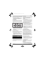
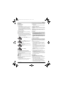
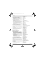
1
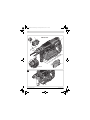
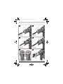
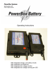
OBJ_BUCH-283-007.book Page 1 Monday, October 21, 2013 11:35 AM Robert Bosch GmbH Power Tools Division 70745 Leinfelden-Echterdingen Germany www.bosch-pt.com GBH Professional 36 V-LI | 36 VF-LI 1 619 92A 065 (2013.10) PS / 250 EURO de en fr es pt it nl Originalbetriebsanleitung Original instructions Notice originale Manual original Manual original Istruzioni originali Oorspronkelijke gebruiksaanwijzing da Original brugsanvisning sv Bruksanvisning i original no Original driftsinstruks fi Alkuperäiset ohjeet el Πρωτότυπο οδηγιών χρήσης tr pl cs sk hu ru uk kk ro bg Orijinal işletme talimatı Instrukcja oryginalna Původní návod k používání Pôvodný návod na použitie Eredeti használati utasítás Оригинальное руководство по эксплуатации Оригінальна інструкція з експлуатації Пайдалану нұсқаулығының түпнұсқасы Instrucţiuni originale Оригинална инструкция mk sr sl hr et lv lt ar fa Оригинално упатство за работа Originalno uputstvo za rad Izvirna navodila Originalne upute za rad Algupärane kasutusjuhend Instrukcijas oriģinālvalodā Originali instrukcija ςТЎϩХʉ ЌТϾϦφЍʉ ʌμВТЎϺυ ΖЎϩʉ ˒μВЖЙʉʓ ИͳϞφЁʑ OBJ_BUCH-283-007.book Page 3 Monday, October 21, 2013 11:35 AM 3| GBH 36 VF-LI 1 7 6 2 3 5 8 4 9 10 11 12 14 13 15 16 17 18 19 7 GBH 36 V-LI 19 A 19 1 619 92A 065 | (21.10.13) Bosch Power Tools OBJ_BUCH-283-007.book Page 4 Monday, October 21, 2013 11:35 AM 4| B 18 C 5 3 20 X 13 D GBH 36 V-LI E 6 23 GBH 36 VF-LI F GBH 36 VF-LI G 5 1 619 92A 065 | (21.10.13) Bosch Power Tools OBJ_BUCH-283-007.book Page 5 Monday, October 21, 2013 11:35 AM 5| H I 22 22 21 21 GBH 36 V-LI GBH 36 V-LI J 24 GBH 36 VF-LI 25 K 24 25 GBH 36 VF-LI L M 8 26 1 619 92A 065 | (21.10.13) Bosch Power Tools OBJ_BUCH-283-007.book Page 14 Monday, October 21, 2013 11:35 AM 14 | English English Safety Notes General Power Tool Safety Warnings Read all safety warnings and all instructions. Failure to follow the warnings and instructions may result in electric shock, fire and/or serious injury. Save all warnings and instructions for future reference. The term “power tool” in the warnings refers to your mainsoperated (corded) power tool or battery-operated (cordless) power tool. WARNING Work area safety Keep work area clean and well lit. Cluttered or dark areas invite accidents. Do not operate power tools in explosive atmospheres, such as in the presence of flammable liquids, gases or dust. Power tools create sparks which may ignite the dust or fumes. Keep children and bystanders away while operating a power tool. Distractions can cause you to lose control. Electrical safety Power tool plugs must match the outlet. Never modify the plug in any way. Do not use any adapter plugs with earthed (grounded) power tools. Unmodified plugs and matching outlets will reduce risk of electric shock. Avoid body contact with earthed or grounded surfaces, such as pipes, radiators, ranges and refrigerators. There is an increased risk of electric shock if your body is earthed or grounded. Do not expose power tools to rain or wet conditions. Water entering a power tool will increase the risk of electric shock. Do not abuse the cord. Never use the cord for carrying, pulling or unplugging the power tool. Keep cord away from heat, oil, sharp edges and moving parts. Damaged or entangled cords increase the risk of electric shock. When operating a power tool outdoors, use an extension cord suitable for outdoor use. Use of a cord suitable for outdoor use reduces the risk of electric shock. If operating a power tool in a damp location is unavoidable, use a residual current device (RCD) protected supply. Use of an RCD reduces the risk of electric shock. Personal safety Stay alert, watch what you are doing and use common sense when operating a power tool. Do not use a power tool while you are tired or under the influence of drugs, alcohol or medication. A moment of inattention while operating power tools may result in serious personal injury. Use personal protective equipment. Always wear eye protection. Protective equipment such as dust mask, non-skid safety shoes, hard hat, or hearing protection used for appropriate conditions will reduce personal injuries. 1 619 92A 065 | (21.10.13) Prevent unintentional starting. Ensure the switch is in the off-position before connecting to power source and/or battery pack, picking up or carrying the tool. Carrying power tools with your finger on the switch or energising power tools that have the switch on invites accidents. Remove any adjusting key or wrench before turning the power tool on. A wrench or a key left attached to a rotating part of the power tool may result in personal injury. Do not overreach. Keep proper footing and balance at all times. This enables better control of the power tool in unexpected situations. Dress properly. Do not wear loose clothing or jewellery. Keep your hair, clothing and gloves away from moving parts. Loose clothes, jewellery or long hair can be caught in moving parts. If devices are provided for the connection of dust extraction and collection facilities, ensure these are connected and properly used. Use of dust collection can reduce dust-related hazards. Power tool use and care Do not force the power tool. Use the correct power tool for your application. The correct power tool will do the job better and safer at the rate for which it was designed. Do not use the power tool if the switch does not turn it on and off. Any power tool that cannot be controlled with the switch is dangerous and must be repaired. Disconnect the plug from the power source and/or the battery pack from the power tool before making any adjustments, changing accessories, or storing power tools. Such preventive safety measures reduce the risk of starting the power tool accidentally. Store idle power tools out of the reach of children and do not allow persons unfamiliar with the power tool or these instructions to operate the power tool. Power tools are dangerous in the hands of untrained users. Maintain power tools. Check for misalignment or binding of moving parts, breakage of parts and any other condition that may affect the power tool’s operation. If damaged, have the power tool repaired before use. Many accidents are caused by poorly maintained power tools. Keep cutting tools sharp and clean. Properly maintained cutting tools with sharp cutting edges are less likely to bind and are easier to control. Use the power tool, accessories and tool bits etc. in accordance with these instructions, taking into account the working conditions and the work to be performed. Use of the power tool for operations different from those intended could result in a hazardous situation. Battery tool use and care Recharge only with the charger specified by the manufacturer. A charger that is suitable for one type of battery pack may create a risk of fire when used with another battery pack. Bosch Power Tools OBJ_BUCH-283-007.book Page 15 Monday, October 21, 2013 11:35 AM English | 15 Use power tools only with specifically designated battery packs. Use of any other battery packs may create a risk of injury and fire. When battery pack is not in use, keep it away from other metal objects, like paper clips, coins, keys, nails, screws or other small metal objects, that can make a connection from one terminal to another. Shorting the battery terminals together may cause burns or a fire. Under abusive conditions, liquid may be ejected from the battery; avoid contact. If contact accidentally occurs, flush with water. If liquid contacts eyes, additionally seek medical help. Liquid ejected from the battery may cause irritation or burns. Service Have your power tool serviced by a qualified repair person using only identical replacement parts. This will ensure that the safety of the power tool is maintained. Hammer Safety Warnings Wear ear protectors. Exposure to noise can cause hearing loss. Use auxiliary handle(s), if supplied with the tool. Loss of control can cause personal injury. Hold the tool by the insulated gripping surfaces when performing operations where the application tool or the screw could contact hidden wiring or its own power cord. Contact with a “live” wire will also make exposed metal parts of the power tool “live” and shock the operator. Use appropriate detectors to determine if utility lines are hidden in the work area or call the local utility company for assistance. Contact with electric lines can lead to fire and electric shock. Damaging a gas line can lead to explosion. Penetrating a water line causes property damage. When working with the machine, always hold it firmly with both hands and provide for a secure stance. The power tool is guided more secure with both hands. Secure the workpiece. A workpiece clamped with clamping devices or in a vice is held more secure than by hand. Always wait until the machine has come to a complete stop before placing it down. The tool insert can jam and lead to loss of control over the power tool. Do not open the battery. Danger of short-circuiting. Protect the battery against heat, e. g., against continuous intense sunlight, fire, water, and moisture. Danger of explosion. In case of damage and improper use of the battery, vapours may be emitted. Ventilate the area and seek medical help in case of complaints. The vapours can irritate the respiratory system. Use the battery only in conjunction with your Bosch power tool. This measure alone protects the battery against dangerous overload. The battery can be damaged by pointed objects such as nails or screwdrivers or by force applied externally. An internal short circuit can occur and the battery can burn, smoke, explode or overheat. Bosch Power Tools Product Description and Specifications Read all safety warnings and all instructions. Failure to follow the warnings and instructions may result in electric shock, fire and/or serious injury. While reading the operating instructions, unfold the graphics page for the machine and leave it open. Intended Use The machine is intended for hammer drilling in concrete, brick and stone, as well as for light chiselling work. It is also suitable for drilling without impact in wood, metal, ceramic and plastic. Machines with electronic control and right/left rotation are also suitable for screwdriving. Product Features The numbering of the product features refers to the illustration of the machine on the graphics page. 1 Quick change keyless chuck (GBH 36 VF-LI) 2 SDS-plus quick change chuck (GBH 36 VF-LI) 3 SDS-plus tool holder 4 Dust protection cap 5 Locking sleeve 6 Lock ring for rapid-change chuck (GBH 36 VF-LI) 7 Handle (insulated gripping surface) 8 Rotational direction switch 9 On/Off switch 10 Release button for mode selector switch 11 Mode selector switch 12 Battery unlocking button 13 Button for depth stop adjustment 14 Temperature control indicator 15 Battery charge-control indicator 16 Button for charge-control indicator 17 Battery pack* 18 Depth stop 19 Auxiliary handle (insulated gripping surface) 20 Keyless chuck(GBH 36 V-LI) * 21 Front sleeve of the keyless chuck (GBH 36 VF-LI) * 22 Rear sleeve of the keyless chuck (GBH 36 VF-LI) * 23 Drill chuck mounting (GBH 36 VF-LI) 24 Front sleeve of the quick change keyless chuck (GBH 36 VF-LI) 25 Retaining ring of the quick change keyless chuck (GBH 36 VF-LI) 26 Universal bit holder with SDS-plus shank* *Accessories shown or described are not part of the standard delivery scope of the product. A complete overview of accessories can be found in our accessories program. 1 619 92A 065 | (21.10.13) OBJ_BUCH-283-007.book Page 16 Monday, October 21, 2013 11:35 AM 16 | English Technical Data Rotary Hammer Article number Speed control Stop rotation Right/left rotation Quick change chuck Rated voltage Rated power input Output power Impact rate Impact energy per stroke according to EPTA-Procedure 05/2009 Rated speed – Right rotation – Left rotation Tool holder Spindle collar diameter Drilling diameter, max.: – Concrete – Brickwork (with core bit) – Steel – Wood Weight according to EPTA-Procedure 01/2003 V= W W min-1 GBH 36 V-LI GBH 36 VF-LI 3 611 J00 R.. 3 611 J01 R.. – 36 36 600 600 430 430 0 –4260 0 –4260 J 2.8 2.8 min-1 min-1 0 –960 0 –930 SDS-plus 0 –960 0 –930 SDS-plus mm 50 50 mm 26 26 mm mm mm 68 13 30 68 13 30 kg 3.9/4.4* 4.0/4.5* Declaration of Conformity * dependent of the battery pack being used Battery Permitted ambient temperature – when charging – during operation* – during storage Recommended batteries °C °C °C 0...+45 –20...+50 –20...+60 GBA 36V XXAh H-. * Limited performance at temperatures <0 °C Noise/Vibration Information Measured sound values determined according to EN 60745. Typically the A-weighted noise levels of the product are: Sound pressure level 91 dB(A); sound power level 102 dB(A). Uncertainty K=3 dB. Wear hearing protection! GBH 36 V-LI Vibration total values ah (triax vector sum) and uncertainty K determined according to EN 60745: Hammer drilling into concrete: ah =19 m/s2, K=1.5 m/s2, Chiselling: ah =11.5 m/s2, K=1.5 m/s2, Drilling in metal: ah <2.5 m/s2, K=1.5 m/s2, Screwdriving without impact: ah <2.5 m/s2, K=1.5 m/s2 1 619 92A 065 | (21.10.13) GBH 36 VF-LI Vibration total values ah (triax vector sum) and uncertainty K determined according to EN 60745: Hammer drilling into concrete: ah =19 m/s2, K=1.5 m/s2, Chiselling: ah =11 m/s2, K=1.5 m/s2, Drilling in metal: ah <2.5 m/s2, K=1.5 m/s2, Screwdriving without impact: ah <2.5 m/s2, K=1.5 m/s2 The vibration level given in this information sheet has been measured in accordance with a standardised test given in EN 60745 and may be used to compare one tool with another. It may be used for a preliminary assessment of exposure. The declared vibration emission level represents the main applications of the tool. However if the tool is used for different applications, with different accessories or insertion tools or is poorly maintained, the vibration emission may differ. This may significantly increase the exposure level over the total working period. An estimation of the level of exposure to vibration should also take into account the times when the tool is switched off or when it is running but not actually doing the job. This may significantly reduce the exposure level over the total working period. Identify additional safety measures to protect the operator from the effects of vibration such as: maintain the tool and the accessories, keep the hands warm, organisation of work patterns. We declare under our sole responsibility that the product described under “Technical Data” is in conformity with the following standards or standardization documents: EN 60745 according to the provisions of the directives 2011/65/EU, 2004/108/EC, 2006/42/EC. Technical file (2006/42/EC) at: Robert Bosch GmbH, PT/ETM9, D-70745 Leinfelden-Echterdingen Henk Becker Helmut Heinzelmann Executive Vice President Head of Product Certification Engineering PT/ETM9 Robert Bosch GmbH, Power Tools Division D-70745 Leinfelden-Echterdingen Leinfelden, 21.10.2013 Assembly Battery Charging Use only the battery chargers listed on the accessories page. Only these battery chargers are matched to the lithium ion battery of your power tool. Note: The battery is supplied partially charged. To ensure full capacity of the battery, completely charge the battery in the battery charger before using your power tool for the first time. The lithium ion battery can be charged at any time without reducing its service life. Interrupting the charging procedure does not damage the battery. Bosch Power Tools OBJ_BUCH-283-007.book Page 17 Monday, October 21, 2013 11:35 AM English | 17 The lithium ion battery is protected against deep discharging by the “Electronic Cell Protection (ECP)”. When the battery is empty, the machine is switched off by means of a protective circuit: The inserted tool no longer rotates. Do not continue to press the On/Off switch after the machine has been automatically switched off. The battery can be damaged. Removing the battery The battery 17 is equipped with two locking levels that should prevent the battery from falling out when pushing the battery unlocking button 12 unintentionally. As long as the battery is inserted in the power tool, it is held in position by means of a spring. To remove the battery 17: – Push the battery against the base of the power tool (1.) and at the same time press the battery unlocking button 12 (2.). – Pull the battery out of the power tool until a red stripe becomes visible (3.). – Press the battery unlocking button 12 again and pull out the battery completely. Battery Charge-control Indication The three green LEDs of the battery charge-control indicator 15 indicate the charge condition of the battery 17. For safety reasons, it is only possible to check the status of the charge condition when the machine is at a standstill. – Push button 16 to indicate the charge condition (also possible when the battery is removed). The battery chargecontrol indicator automatically goes out after approx. 5 seconds. LED Continuous lighting 3 x green Continuous lighting 2 x green Continuous lighting 1 x green Flashing light 1 x green Capacity ≥2/3 ≥1/3 <1/3 Reserve When no LED lights up after pushing button 16, then the battery is defective and must be replaced. During the charging procedure, the three green LEDs light up one after the other and briefly go out. The battery is fully charged when the three green LEDs light up continuously. The three LEDs go out again approx. 5 minutes after the battery has been fully charged. Auxiliary Handle Operate your machine only with the auxiliary handle 19. Changing the position of the auxiliary handle (see figure A) The auxiliary handle 19 can be set to any position for a secure and low-fatigue working posture. – Turn the bottom part of the auxiliary handle 19 in counterclockwise direction and swivel the auxiliary handle 19 to the desired position. Then retighten the bottom part of the auxiliary handle 19 by turning in clockwise direction. Pay attention that the clamping band of the auxiliary handle is positioned in the groove on the housing as intended for. Adjusting the Drilling Depth (see figure B) The required drilling depth X can be set with the depth stop 18. – Press the button for the depth stop adjustment 13 and insert the depth stop into the auxiliary handle 19. The knurled surface of the depth stop 18 must face downward. – Insert the SDS-plus drilling tool to the stop into the SDSplus tool holder 3. Otherwise, the movability of the SDSplus drilling tool can lead to incorrect adjustment of the drilling depth. – Pull out the depth stop until the distance between the tip of the drill bit and the tip of the depth stop correspond with the desired drilling depth X. Selecting Drill Chucks and Tools For hammer drilling and chiselling, SDS-plus tools are required that are inserted in the SDS-plus drill chuck. For drilling without impact in wood, metal, ceramic and plastic as well as for screwdriving, tools without SDS-plus are used (e.g., drills with cylindrical shank). For these tools, a keyless chuck or a key type drill chuck are required. GBH 36 VF-LI: The SDS-plus quick change chuck 2 can easily be replaced against the quick change keyless chuck 1 provided. Changing the Keyless Chuck (GBH 36 V-LI) To work with tools without SDS-plus (e.g., drills with cylindrical shank), a suitable drill chuck must be mounted (key type drill chuck or keyless chuck, accessories). Inserting the Keyless Chuck (see figure C) – Clean the shank end of the adapter shank and apply a light coat of grease. – Insert the keyless chuck 20 with the adapter shank into the tool holder with a turning motion until it automatically locks. – Check the locking effect by pulling the keyless chuck. Removing the Keyless Chuck – Push the locking sleeve 5 toward the rear and pull out the keyless chuck20. Removing/Inserting the Quick Change Chuck (GBH 36 VF-LI) Removing the Quick Change Chuck (see figure D) – Pull the lock ring for the quick change chuck 6 toward the rear, hold it in this position and pull off the SDS-plus quick Bosch Power Tools 1 619 92A 065 | (21.10.13) OBJ_BUCH-283-007.book Page 18 Monday, October 21, 2013 11:35 AM 18 | English change chuck 2 or the quick change keyless chuck 1 toward the front. – After removing, protect the replacement chuck against contamination. Inserting the Quick Change Chuck (see figure E) – Before inserting, clean the quick change chuck and apply a light coat of grease to the shank end. – Grasp the SDS-plus quick change chuck 2 or the quick change keyless chuck 1 completely with your hand. Slide the quick change chuck with a turning motion onto the drill chuck mounting 23 until a distinct latching noise is heard. – The quick change chuck is automatically locked. Check the locking effect by pulling the quick change chuck. Changing the Tool The dust protection cap 4 largely prevents the entry of drilling dust into the tool holder during operation. When inserting the tool, take care that the dust protection cap 4 is not damaged. A damaged dust protection cap should be changed immediately. We recommend having this carried out by an after-sales service. Inserting SDS-plus Drilling Tools (see figure F) The SDS-plus drill chuck allows for simple and convenient changing of drilling tools without the use of additional tools. – GBH 36 VF-LI: Insert the SDS-plus quick change chuck 2. – Clean and lightly grease the shank end of the tool. – Insert the tool in a twisting manner into the tool holder until it latches itself. – Check the latching by pulling the tool. As a requirement of the system, the SDS-plus drilling tool can move freely. This causes a certain radial run-out at no-load, which has no effect on the accuracy of the drill hole, as the drill bit centres itself upon drilling. Removing SDS-plus Drilling Tools (see figure G) – Push back the locking sleeve 5 and remove the tool. Inserting Drilling Tools without SDS-plus (GBH 36 V-LI) (see figure H) Note: Do not use tools without SDS-plus for hammer drilling or chiselling! Tools without SDS-plus and their drill chucks are damaged by hammer drilling or chiselling. – Insert the keyless chuck 20. – Hold the rear sleeve 22 of the keyless chuck 20 and turn the front sleeve 21 in anticlockwise direction until the tool can be inserted. Insert the tool. – Tightly hold the rear sleeve of the keyless chuck 20 and firmly turn the front sleeve clockwise by hand until the locking action is no longer heard. This automatically locks the drill chuck. – Check the tight seating by pulling the tool. Note: If the tool holder was opened to the stop, then a latching noise possibly may be heard while closing the tool holder and the tool holder will not close. In this case, turn the front sleeve 21 once in anticlockwise direction. Afterwards, the tool holder can be closed (tightened). – Turn the mode selector switch 11 to the “drilling” position. 1 619 92A 065 | (21.10.13) Removing Drilling Tools without SDS-plus (GBH 36 V-LI) (see figure I) – Firmly hold the rear sleeve 22 of the keyless chuck and turn the front sleeve 21 of the keyless chuck in anticlockwise direction until the drilling tool can be removed. Inserting Drilling Tools without SDS-plus (GBH 36 VF-LI) (see figure J) Note: Do not use tools without SDS-plus for hammer drilling or chiselling! Tools without SDS-plus and their drill chucks are damaged by hammer drilling or chiselling. – Insert the quick change keyless chuck 1. – Firmly hold the retaining ring 25 of the quick change chuck. Open the tool holder by turning the front sleeve 24 until the tool can be inserted. Tightly hold the retaining ring 25 and firmly turn the front sleeve 24 in the direction of the arrow until a distinct latching noise can be heard. – Check the tight seating by pulling the tool. Note: If the tool holder was opened to the stop, then the latching noise possibly may be heard while closing the tool holder and the tool holder will not close. In this case, turn the front sleeve 24 once in the opposite direction of the arrow. Afterwards, the tool holder can be closed (tightened) again. – Turn the mode selector switch 11 to the “drilling” position. Removing Drilling Tools without SDS-plus (GBH 36 VF-LI) (see figure K) – Firmly hold the retaining ring 25 of the quick change chuck. Open the tool holder by turning the front sleeve 24 in the direction of the arrow until the tool can be removed. Dust Extraction with GDE 16 Plus (Accessory) Dusts from materials such as lead-containing coatings, some wood types, minerals and metal can be harmful to one’s health. Touching or breathing-in the dusts can cause allergic reactions and/or lead to respiratory infections of the user or bystanders. Certain dusts, such as oak or beech dust, are considered as carcinogenic, especially in connection with wood-treatment additives (chromate, wood preservative). Materials containing asbestos may only be worked by specialists. – As far as possible, use a dust extraction system suitable for the material. – Provide for good ventilation of the working place. – It is recommended to wear a P2 filter-class respirator. Observe the relevant regulations in your country for the materials to be worked. Prevent dust accumulation at the workplace. Dusts can easily ignite. A GDE 16 Plus (accessory) is required for dust extraction. The vacuum cleaner must be suitable for the material being worked. When vacuuming dry dust that is especially detrimental to health or carcinogenic, use a special vacuum cleaner. Bosch Power Tools OBJ_BUCH-283-007.book Page 19 Monday, October 21, 2013 11:35 AM English | 19 Operation Starting Operation Inserting the battery – Set the rotational direction switch 8 to the centre position to protect the power tool against accidental starting. – Insert the charged battery 17 from the front into the base of the power tool. Push the battery completely into the base until the red stripe can no longer be seen and the battery is securely locked. Setting the operating mode The operating mode of the power tool is selected with the mode selector switch 11. Note: Change the operating mode only when the machine is switched off! Otherwise, the machine can be damaged. – To change the operating mode, push the release button 10 and turn the mode selector switch 11 to the requested position until it can be heard to latch. Position for hammer drilling in concrete or stone Position for drilling without impact in wood, metal, ceramic and plastic as well as for screwdriving Vario-Lock position for adjustment of the chiselling position The mode selector switch 11 does not latch in this position. Position for chiselling Reversing the rotational direction (see figure L) The rotational direction switch 8 is used to reverse the rotational direction of the machine. However, this is not possible with the On/Off switch 9 actuated. Right rotation: Push the rotational direction switch 8 left to the stop. Left rotation: Push the rotational direction switch 8 right to the stop. Set the direction of rotation for hammer drilling, drilling and chiselling always to right rotation. Switching On and Off To save energy, only switch the power tool on when using it. – To start the machine, press the On/Off switch 9. Bosch Power Tools When starting the machine for the first time, a starting delay is possible, as the electronic system of the power tool has to configure itself first. – To switch off the machine, release the On/Off switch 9. Setting the Speed/Impact Rate The speed/impact rate of the switched on power tool can be variably adjusted, depending on how far the On/Off switch 9 is pressed. Light pressure on the On/Off switch 9 results in low speed/impact rate. Further pressure on the switch increases the speed/impact rate. Safety Clutch If the tool insert becomes caught or jammed, the drive to the drill spindle is interrupted. Because of the forces that occur, always hold the power tool firmly with both hands and provide for a secure stance. If the power tool jams, switch the machine off and loosen the tool insert. When switching the machine on with the drilling tool jammed, high reaction torques can occur. Temperature Control Indicator The red LED of the temperature control indicator 14 signals that the battery or the electronics of the power tool (when the battery is inserted) are not within the optimum temperature range. In this case, the power tool will not operate at full capacity. Temperature control of the battery: – The red LED 14 lights up continuously after inserting the battery into the charger: The battery is not within the charging temperature range between 0 °C and 45 °C and cannot be charged. – The red LED 14 flashes when pushing button 16 or pressing the On/Off switch 9 (when the battery is inserted): The battery is not wihin the temperature range for operation of –10 °C to +60 °C. – For battery temperatures over 70 °C, the power tool switches off until the battery is in the optimal temperature range again. Temperature control of the power tool electronics: – The red LED 14 lights up continuously when pressing the On/Off switch 9: The temperature of the machine’s electronics is below 5 °C or above 75 °C. – At a temperature above 90 °C , the electronics of the power tool switch off until the temperature is within the allowable temperature range again. Working Advice Changing the Chiselling Position (Vario-Lock) The chisel can be locked in 36 positions. In this manner, the optimum working position can be set for each application. – Insert the chisel into the tool holder. – Turn the mode selector switch 11 to the “Vario-Lock” position (see “Setting the operating mode”, page 19). – Turn the tool holder to the desired chiselling position. – Turn the mode selector switch 11 to the “chiselling” position. The tool holder is now locked. 1 619 92A 065 | (21.10.13) OBJ_BUCH-283-007.book Page 20 Monday, October 21, 2013 11:35 AM 20 | English – For chiselling, set the rotation direction to right rotation. Inserting Screwdriver Bits (see figure M) Apply the power tool to the screw/nut only when it is switched off. Rotating tool inserts can slip off. To work with screwdriver bits, a universal bit holder 26 with SDS-plus shank (accessory) is required. – Clean the shank end of the adapter shank and apply a light coat of grease. – Insert the universal bit holder with a turning motion into the tool holder until it automatically locks. – Check the locking effect by pulling the universal bit holder. – Insert a screwdriver bit into the universal bit holder. Use only screwdriver bits that match the screw head. – To remove the universal bit holder, pull the locking sleeve 5 toward the rear and remove the universal bit holder 26 out of the tool holder. Recommendations for Optimal Handling of the Battery Protect the battery against moisture and water. Store the battery only within a temperature range between 0 °C and 50 °C. As an example, do not leave the battery in the car in summer. Occasionally clean the venting slots of the battery using a soft, clean and dry brush. A significantly reduced working period after charging indicates that the battery is used and must be replaced. Observe the notes for disposal. Maintenance and Service Maintenance and Cleaning Before any work on the machine itself (e. g. maintenance, tool change, etc.) as well as during transport and storage, remove the battery from the power tool. There is danger of injury when unintentionally actuating the On/Off switch. For safe and proper working, always keep the machine and ventilation slots clean. A damaged dust protection cap should be changed immediately. We recommend having this carried out by an after-sales service. – Clean the tool holder 3 each time after using. After-sales Service and Application Service In all correspondence and spare parts order, please always include the 10-digit article number given on the type plate of the machine. Our after-sales service responds to your questions concerning maintenance and repair of your product as well as spare parts. Exploded views and information on spare parts can also be found under: www.bosch-pt.com Bosch’s application service team will gladly answer questions concerning our products and their accessories. 1 619 92A 065 | (21.10.13) Great Britain Robert Bosch Ltd. (B.S.C.) P.O. Box 98 Broadwater Park North Orbital Road Denham Uxbridge UB 9 5HJ Tel. Service: (0844) 7360109 Fax: (0844) 7360146 E-Mail: [email protected] Ireland Origo Ltd. Unit 23 Magna Drive Magna Business Park City West Dublin 24 Tel. Service: (01) 4666700 Fax: (01) 4666888 Australia, New Zealand and Pacific Islands Robert Bosch Australia Pty. Ltd. Power Tools Locked Bag 66 Clayton South VIC 3169 Customer Contact Center Inside Australia: Phone: (01300) 307044 Fax: (01300) 307045 Inside New Zealand: Phone: (0800) 543353 Fax: (0800) 428570 Outside AU and NZ: Phone: +61 3 95415555 www.bosch.com.au Republic of South Africa Customer service Hotline: (011) 6519600 Gauteng – BSC Service Centre 35 Roper Street, New Centre Johannesburg Tel.: (011) 4939375 Fax: (011) 4930126 E-Mail: [email protected] KZN – BSC Service Centre Unit E, Almar Centre 143 Crompton Street Pinetown Tel.: (031) 7012120 Fax: (031) 7012446 E-Mail: [email protected] Western Cape – BSC Service Centre Democracy Way, Prosperity Park Milnerton Tel.: (021) 5512577 Fax: (021) 5513223 E-Mail: [email protected] Bosch Power Tools