1
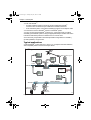
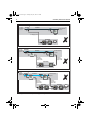
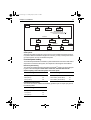
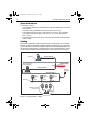
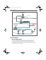
81300_1.book Page 1 Tuesday, May 22, 2007 2:53 PM
SeaTalkng
Reference Manual
Document reference: 81300-1
Date: June 2007
81300_1.book Page 2 Tuesday, May 22, 2007 2:53 PM
Raymarine, SeaTalk, SeaTalk2, SeaTalkng and ST70 are trademarks of Raymarine plc.
DeviceNet is a trademark of Open DeviceNet Vendor Association Inc
© Handbook contents copyright Raymarine plc
81300_1.book Page i Tuesday, May 22, 2007 2:53 PM
Contents
Contents
Preface ........................................................................................................................... iii
WARNING: Electrical safety....................................................................... iii
EMC conformance ...................................................................................................iii
Product documents ..................................................................................................iii
Product disposal ......................................................................................................iii
Waste Electrical and Electronic (WEEE) Directive ...................................................iii
Chapter 1:Description ............................................................................................... 1
1.1 SeaTalkng overview ....................................................................................... 1
Introduction .................................................................................................... 1
Terminology.................................................................................................... 1
Connectability................................................................................................. 1
1.2 Hardware ....................................................................................................... 1
Color coding ................................................................................................... 2
Important: you must fit Terminators ................................................................. 2
Available parts ................................................................................................ 2
Other cables ............................................................................................... 4
Connectors..................................................................................................... 4
1.3 Using SeaTalkng ............................................................................................. 4
Typical applications ........................................................................................ 5
General guidelines when using with other systems......................................... 6
Basic rules .................................................................................................. 6
Limitations when SeaTalk(1) products are connected .............................. 6
Using with SeaTalk(1)................................................................................. 6
Chapter 2:Installation ............................................................................................... 9
2.1 Preparation for installation ............................................................................. 9
EMC installation guidelines............................................................................. 9
Remember .................................................................................................. 9
Suppression ferrites ....................................................................................... 9
Connections to non-Raymarine equipment..................................................... 9
Tools required................................................................................................. 9
System structures......................................................................................... 10
Power supply considerations ........................................................................ 10
Product loading......................................................................................... 10
Power sources .......................................................................................... 10
Protection.................................................................................................. 10
Power connection point ............................................................................ 10
Balanced system .................................................................................... 10
Small systems ........................................................................................ 11
Permitted power loading ........................................................................... 11
Balanced system loading ........................................................................ 11
Unbalanced system loading ................................................................... 11
System limitations......................................................................................... 12
Cabling ......................................................................................................... 12
2.2 Procedures .................................................................................................. 13
General requirements................................................................................... 13
Making connections .................................................................................. 14
Running cables ......................................................................................... 14
i
81300_1.book Page ii Tuesday, May 22, 2007 2:53 PM
ii
SeaTalkng Reference Manual
Installing Backbone ...................................................................................... 15
CAUTION: Backbone Extender ............................................................... 15
Connecting spurs.......................................................................................... 15
Connecting power......................................................................................... 15
CAUTION: Do not connect power until installation is complete . 15
Balanced system ...................................................................................... 15
Unbalanced system .................................................................................. 16
Fitting Terminators ........................................................................................ 16
Fitting Blanking Plugs ................................................................................... 16
Chapter 3:Post installation procedures ............................................................. 17
3.1 Checks ......................................................................................................... 17
3.2 Maintenance ................................................................................................ 17
3.3 Troubleshooting ........................................................................................... 17
Technical support.......................................................................................... 17
World wide web ........................................................................................ 17
Telephone help line .................................................................................. 18
Help us to help you ................................................................................... 18
Index.............................................................................................................................. 19
81300_1.book Page iii Tuesday, May 22, 2007 2:53 PM
Preface
iii
Preface
WARNING: Electrical safety
Make sure you have switched off the power supply before you start
installing this product.
EMC conformance
All Raymarine equipment and accessories are designed to the best industry
standards for use in the recreational marine environment.
The design and manufacture of Raymarine equipment and accessories conform to
the appropriate Electromagnetic Compatibility (EMC) standards, but correct
installation is required to ensure that performance is not compromised.
Product documents
This manual gives information on the Raymarine SeaTalkng system. It should be read
in conjunction with the documents for the individual products that connect to
SeaTalkng.
To the best of our knowledge, the information in this document was correct when it
went to press. However, Raymarine cannot accept liability for any inaccuracies or
omissions in product documents.
In addition, our policy of continuous product improvement may change specifications
without notice. Therefore, Raymarine cannot accept liability for any differences
between the product and the accompanying documents.
Product disposal
Waste Electrical and Electronic (WEEE) Directive
The WEEE Directive requires the recycling of waste electrical and electronic
equipment.
Whilst the WEEE Directive does not apply to some of Raymarine's products,
we support its policy and ask you to be aware of how to dispose of this product.
The crossed out wheelie bin symbol, illustrated above, and found on our products
signifies that this product should not be disposed of in general waste or landfill.
Please contact your local dealer, national distributor or Raymarine Technical Services
for information on product disposal.
81300_1.book Page iv Tuesday, May 22, 2007 2:53 PM
iv
SeaTalkng Reference Manual
81300_1.book Page 1 Tuesday, May 22, 2007 2:53 PM
Chapter 1: Description
1
Chapter 1: Description
1.1 SeaTalkng overview
Introduction
SeaTalkng is an interconnection bus for Raymarine products, and comprises a main
backbone to which Raymarine products are connected via spur cables (see Figure
1-1).
Power
Supply
Instrument
Display
Spur
Spur
Backbone
Terminator
Spur
Spur
Spur
Instrument Instrument Instrument
Backbone
Spur
Terminator
Spur
Transducer Transducer
Adaptor cable
Adaptor cable
NMEA2000
SeaTalk(1)
D10238-1
ng
Figure 1-1 SeaTalk overview
Terminology
Raymarine produces SeaTalk, SeaTalk2 and SeaTalkng proprietary bus systems. In
this book, in the interests of clarity, SeaTalk is referred to as ‘SeaTalk(1)’.
Connectability
Specific Raymarine products (e.g. ST70 instruments) perform a bridging function, to
enable you to connect SeaTalkng to SeaTalk(1) products via appropriate adaptor
cables. Adaptor cables are also available to connect NMEA2000 products.
1.2 Hardware
SeaTalkng comprises a single backbone terminated with two terminators, one at each
end. Spur cables connect the backbone to individual SeaTalkng products.
Small diameter cable connectors are used throughout the system, to make
installation easier. Cables and connectors are color-coded to reduce the likelihood of
misconnection.
A wide range of different cable lengths provides flexibility and obviates the need for
cutting and splicing cables.
Three-way, five- way and in-line connection pieces are available to connect cables, to
deploy SeaTalkng as required.
81300_1.book Page 2 Tuesday, May 22, 2007 2:53 PM
SeaTalkng Reference Manual
2
Color coding
Cables and connectors are color-coded to facilitate correct connection. The color
codes are:
• Backbone is blue.
• Spurs are white.
A power cable is also provided and is color-coded with a red strip.
Important: you must fit Terminators
In order to ensure correct data transmission through a SeaTalkng system, a
Terminator is required at each end of the backbone cable run. Dedicated
Terminators are available for this purpose. Do NOT attempt to run a system that is
not correctly terminated.
Available parts
The following parts are available:
Backbone cable
Part numbers: 1 ft 3 in (400 mm) - A06033
3 ft 3 in (1 m) - A06034
9 ft 10 in (3 m) - A06035
16 ft 4 in (5 m) - A06036
65 ft 7 in(20 m) - A06037
Spur cable
Part numbers:
1 ft 3 in (400 mm) - A06038,
3 ft 3 in (1 m) - A06039
9 ft 10 in (3 m) - A06040
16 ft 4 in (5 m) - A06041
T-Piece
Connects spur to backbone.
Part number: A06028
5-Way Connector
Connects spurs to backbone
Part number: A06064
Backbone Extender
Connects two backbone cables
Part number: A06030
81300_1.book Page 3 Tuesday, May 22, 2007 2:53 PM
Chapter 1: Description
3
Terminator
Fitted at each end of backbone
Part number: A06031
Blanking Plug
Inserted into unused spur connector
positions in 5-way connector & T Piece
Part number: A06032
Elbow Spur cable (1 ft 3 in (400 mm))
For spurs in confined spaces
Part number: A06042
SPX Spur cable
Connects SeaTalkng to Raymarine SPX
Course Computers
Part number: To be announced
Power cable
Connects SeaTalkng 12 V dc supply
Part number: A06049
Stripped End Spur cable
Connects products which do not have
plug-in connectors (e.g. transducer
pods)
Part numbers: 1 m - A06043, 3 m - A06044
SeaTalk Adaptor cable
Connects SeaTalkng products to
SeaTalk(1)
Part number: A06047
SeaTalk2 adaptor cable
Connects SeaTalkng products to
SeaTalk2
Part number: A06048
DeviceNet female adaptor cable
Connects SeaTalkng products to
NMEA2000
Part number: A06045
81300_1.book Page 4 Tuesday, May 22, 2007 2:53 PM
SeaTalkng Reference Manual
4
DeviceNet male adaptor cable
Connects SeaTalkng products to
NMEA2000
Part number: A06046
E-Series Adaptor cable
Connects SeaTalkng products to
Raymarine E-Series Displays
Part number: A06061
SeaTalkng Reference Manual
Part number: 81300-1
Backbone Kit
Part number: A25062
Comprises: Two terminators
One 65 ft 7 in (20 m) Backbone cable
Two 16 ft 4 in (5 m) Backbone cables
Four T Piece connectors
One Power Cable
One SeaTalkng Reference Manual (this book)
Other cables
In addition to the parts listed, a range of connector cables is available from your
Raymarine dealer to connect to other Raymarine products and systems.
Connectors
SeaTalkng connectors are lockable to ensure reliable, secure connectivity. Keyways
on the connectors ensure correct orientation. Locking collars on the SeaTalkng
T-Piece, 5-Way Connector and Backbone Extender rotate to lock the connections.
Molded arrow indicators on the connectors align to show when the connector is
unlocked.
1.3 Using SeaTalkng
A complete SeaTalkng backbone comprises two or more backbone cables connected
in series. There must be only one backbone and this must be terminated with two terminators, one at each end of the backbone. Do NOT connect a terminator to any spur.
In a SeaTalkng system and any system to which it is connected:
• As a general rule, there must only be one data source (transducer) for each data
type. Although some products may be permitted as secondary data sources, do
not duplicate the source for any data unless permission is specifically given in the
relevant product documents.
• There must be only one power source.
It is particularly important to be aware of these requirements when connecting to
another system. For example, in Raymarine SeaTalk(1), power is often supplied from
the system autopilot.
81300_1.book Page 5 Tuesday, May 22, 2007 2:53 PM
Chapter 1: Description
5
You can use SeaTalkng:
• As a self-contained system in which only products fitted with SeaTalkng
connectors are connected via spur cables to the SeaTalkng backbone.
• As an extended system, connected to SeaTalk(1) products via an adaptor cable.
You must NOT connect a SeaTalkng system to a SeaTalk2 system.
You may connect specific SeaTalkng products (e.g. ST70 instruments) to existing
SeaTalk(1) and SeaTalk2 systems, using the appropriate adaptor cables. Refer to the
instructions with these products for details of how to connect them.
As it is obviously not possible to describe all possible configurations for SeaTalkng,
general guidelines, are given here.
Typical applications
A typical SeaTalkng system is shown in Figure 1-2. It comprises the main backbone,
with compatible products connected via spur cables.
,
SeaTalk ng
Wind transducer & pod
CANCEL
ENTER
MENU
CANCEL
ENTER
MENU
Spur
CANCEL
ENTER
Spur
MENU
T Piece
Spur
SeaTalkng Backbone
Terminator
T Piece
5-Way Connector
CANCEL
12 V dc Power
Supply
Power
cable
ENTER
MENU
Spur
CANCEL
ENTER
MENU
Terminator
T Piece
T Piece
SeaTalkng Backbone
T Piece
Speed Pod
&transducer
Spur Spur
Spur
Depth Pod
&transducer
D10194-1
Figure 1-2 Typical basic SeaTalkng system
81300_1.book Page 6 Tuesday, May 22, 2007 2:53 PM
SeaTalkng Reference Manual
6
General guidelines when using with other systems
Basic rules
If SeaTalkng is connected to any other system, ensure that in the combined system:
• You connect only one source for any data type, unless permission is specifically
given in the relevant product documents.
• You connect only one power source.
Limitations when SeaTalk(1) products are connected
If SeaTalkng and SeaTalk(1) products are used together, do NOT connect an
NMEA2000 backbone, as this product combination could compromise the integrity of
the NMEA2000 system.
Using with SeaTalk(1)
Provided you do not want to connect to NMEA2000, you can connect a SeaTalkng
system to SeaTalk(1) using a suitable SeaTalkng bridging product (such as an ST70
instrument) and adaptor cables to connect the two systems.
If you intend doing this, note that:
• You can connect a single SeaTalk(1) network to SeaTalkng using an adaptor cable
and one bridging product (e.g. ST70 instrument).
• You can connect two separate SeaTalk(1) networks to SeaTalkng using different
adaptor cables and bridging products (e.g. ST70 instruments), but the two
SeaTalk(1) networks must NOT be connected together.
Summaries of acceptable and unacceptable SeaTalkng/SeaTalk(1) scenarios are
shown in Figure 1-3 and Figure 1-4 respectively.
81300_1.book Page 7 Tuesday, May 22, 2007 2:53 PM
Chapter 1: Description
7
,
To other
SeaTalkng
products
SeaTalk ng
Backbone
ST70
ST70
Spur
To other SeaTalk ng
products
Spur
CANCEL
ENTER
CANCEL
MENU
ENTER
MENU
ng
SeaTalk
to SeaTalk(1)
adaptor cable
SeaTalk(1)
DISP
To other
SeaTalkng
products
SeaTalk ng
TRUE
APP
VMG
TACK
DEPTH
ALARM
OFFSET
RESET
Backbone
Spur
To other SeaTalk ng
products
ST70
ST70
Spur
CANCEL
ENTER
CANCEL
MENU
ENTER
MENU
ng
ng
SeaTalk
to SeaTalk(1)
adaptor cable
SeaTalk
to SeaTalk(1)
adaptor cable
SeaTalk(1)
SeaTalk(1)
DISP
TRUE
APP
VMG
TACK
DEPTH
ALARM
OFFSET
RESET
DISP
TRUE
APP
VMG
TACK
DEPTH
ALARM
OFFSET
RESET
D10314-1
Figure 1-3 SeaTalkng/SeaTalk(1) acceptable scenarios
81300_1.book Page 8 Tuesday, May 22, 2007 2:53 PM
SeaTalkng Reference Manual
8
To other
SeaTalkng
products
SeaTalk ng
Backbone
To other SeaTalk ng
products
ST70
Spur
Spur
CANCEL
ENTER
MENU
No bridging product
SeaTalk(1)
DISP
To other
SeaTalkng
products
SeaTalk ng
TRUE
APP
VMG
TACK
DEPTH
RESET
OFFSET
ALARM
Backbone
ST70
ST70
Spur
To other SeaTalk ng
products
Spur
CANCEL
ENTER
CANCEL
MENU
ENTER
MENU
ng
SeaTalkng
to SeaTalk(1)
adaptor cable
SeaTalk
to SeaTalk(1)
adaptor cable
SeaTalk(1)
TRUE
APP
DISP
To other
SeaTalkng
products
SeaTalk ng
VMG
TACK
DEPTH
Backbone
Spur
OFFSET
RESET
To other SeaTalk ng
products
ST70
ST70
ALARM
Spur
CANCEL
ENTER
CANCEL
MENU
ENTER
MENU
SeaTalk ng
to SeaTalk(1)
adaptor cable
SeaTalkng
to SeaTalk(1)
adaptor cable
SeaTalk(1)
DISP
TRUE
APP
VMG
TACK
DEPTH
ALARM
SeaTalk(1)
OFFSET
RESET
DISP
TRUE
APP
VMG
TACK
DEPTH
ALARM
OFFSET
RESET
D10330-1
Figure 1-4 SeaTalkng/SeaTalk(1) unacceptable scenarios
81300_1.book Page 9 Tuesday, May 22, 2007 2:53 PM
Chapter 2: Installation
9
Chapter 2: Installation
2.1 Preparation for installation
EMC installation guidelines
Raymarine equipment and accessories conform to the appropriate Electromagnetic
Compatibility (EMC) regulations. This minimizes electromagnetic interference
between equipment, which could otherwise affect the performance of your system.
Correct installation is required to ensure that EMC performance is not compromised.
For optimum EMC performance, we recommend that:
• Raymarine equipment and the cables connected to it are:
• At least 3 ft (1 m) from any equipment transmitting or cables carrying radio
signals e.g. VHF radios, cables and antennas. In the case of SSB radios, the
distance should be increased to 7 ft (2 m).
• More than 7 ft (2 m) from the path of a radar beam. A radar beam can normally
be assumed to spread 20 degrees above and below the radiating element.
• The product is supplied from a separate battery from that used for engine start.
This is important to prevent erratic behavior and data loss which can occur if the
engine start does not have a separate battery.
• Raymarine specified cables are used.
• Cables are not cut or extended unless doing so is detailed in the installation manual.
Remember
Where constraints on the installation prevent any of the above recommendations,
always allow the maximum separation possible between different items of electrical
equipment.
This will provide the best conditions for EMC performance for the installation.
Suppression ferrites
Raymarine cables may be fitted with suppression ferrites. These are important for
correct EMC performance. Any ferrite removed to facilitate installation must be
replaced in the original position immediately installation is complete.
Use only ferrites of the correct type, supplied by Raymarine authorized dealers.
Connections to non-Raymarine equipment
If Raymarine equipment is to be connected to other equipment using a cable not
supplied by Raymarine, a Raymarine suppression ferrite MUST always be attached
to the cable near the Raymarine unit.
Tools required
Before installing SeaTalkng, ensure you have the appropriate tools. In most cases, a
typical fitter’s toolkit should suffice, provided it has tools to enable you to:
• Drill holes for cable runs.
• Connect prepared bare wire ends to terminal blocks.
81300_1.book Page 10 Tuesday, May 22, 2007 2:53 PM
SeaTalkng Reference Manual
10
System structures
Plan the route of the SeaTalkng backbone so that it runs as close as is practicable to
the intended location of each SeaTalkng product, to keep spur lengths to a minimum.
Products connect to the backbone via spur cables. Spurs connect to the backbone via
either a SeaTalkng T-Piece or a SeaTalkng 5-Way Connector.
Power supply considerations
It is important that power for SeaTalkng is provided from only one power source. If you
intend using your SeaTalkng system with any other system (e.g. SeaTalk(1)), power
may already be connected to the other system. If this is the case, do NOT connect an
additional power source to SeaTalkng.
Product loading
The number of products you can connect to a SeaTalkng system depends on the
power each product consumes and on the physical length of the proposed system.
Each Raymarine product has a Load Equivalency Number (LEN), which indicates
how much power it consumes.
Power sources
A SeaTalkng system requires one 12 V dc supply, connected to the SeaTalkng
backbone. This can be provided:
• By a battery.
• From a Raymarine Course Computer, via SeaTalk and/or SeaTalkng.
Note: If a battery is used as a power source, it is recommended that in order to avoid sudden
voltage drops, the battery used for engine starting is NOT used to power SeaTalkng.
On boats with 24 V dc systems, a suitable 24 V to 12 V dc dropper may be used.
Check with Raymarine Customer Support or your Dealer for suitability.
Protection
The power source must be protected by a 5 A fuse or a circuit breaker providing
equivalent protection.
Power connection point
Balanced system
We recommend that as a general rule, power is connected to a SeaTalkng system in
such a way that the current drawn on each side of the power connection point, is
equal.
This is termed a balanced system.
Figure 2-1, shows a theoretical balanced system. In this system the total LEN of the all
products is 40, so the optimum power connection point is a total LEN value of 20 each
end of the backbone.
81300_1.book Page 11 Tuesday, May 22, 2007 2:53 PM
Chapter 2: Installation
11
Backbone
Terminator
Product A
LEN = 4
Product B
LEN = 6
Product C
LEN = 6
Total system LEN = 40
Optimum power connection point = 40 2
= 20 LEN from end of Backbone
Backbone
Product F
LEN = 6
Product E
LEN = 5
Product D
LEN = 4
Backbone
Product G
LEN = 5
Prod. H
LEN = 2
Terminator
Prod. J
LEN = 2
D10347-1
ng
Figure 2-1 Where to connect SeaTalk power in a balanced system
Small systems
Although the preferred method of connection is to form a balanced system as above,
in systems where the backbone length is 60 m or less, you may connect power at one
end of the system, to form an unbalanced system.
Permitted power loading
The total load permissible in a SeaTalkng system is defined in terms of the total LEN of
all products connected to the system, and depends on the length of the backbone.
Balanced system loading
The maximum loading (total LEN) for balanced SeaTalkng systems of various lengths
is given in the following table. Note that in each case, the total LEN must be
divided equally each side of the power connection point.
Backbone length
Total LEN
Backbone length
Total LEN
197 ft (60 m) or less
100
394 ft (120 m)
50
262 ft (80 m)
84
459 to 525 ft (140 to 160 m)
40
328 ft (100 m)
60
591 to 656 ft (180 to 200 m)
32
Unbalanced system loading
The maximum LEN for unbalanced SeaTalkng systems up to 197 ft (60 m) is given in
the following table.
Backbone length
Total LEN
66 ft (20 m)
40
131 ft (40 m
20
197 ft (60 m)
14
81300_1.book Page 12 Tuesday, May 22, 2007 2:53 PM
SeaTalkng Reference Manual
12
System limitations
In a SeaTalkng system:
• The total length of backbone cable between the two Terminators must not exceed
656 ft (200 m).
• The length of any individual spur must not exceed 16 ft 4 in (5 m).
• The total length of all spurs must not exceed 98 ft 5 in (30) m. So for example,
your system could have 30 spurs, each of 3 ft 3 in (1 m), or 6 spurs each of
16 ft 4 in (5 m).
• The total LEN in the system must not exceed the value detailed under Permitted
power loading.
Cabling
When planning SeaTalkng cable routes (see Figure 2-2 and Figure 2-3), ensure that
the EMC conditions are fulfilled (see EMC installation guidelines above). In particular,
do not route cables near fluorescent lights, engines and radio transmitting equipment,
as these may cause interference. Taking this into account, plan the backbone route to
run as close as possible to the intended locations of the products to be connected.
Cockpit
Spurs to steering instruments/displays
SeaTalkng Backbone
Terminator
5-Way Connector
Below decks
Spurs to chart table
instruments/displays
T-Piece
Power cable
SeaTalkng Backbone
SPX Spur
to autopilot
5-Way Connector
SeaTalkng Backbone
Depth
transducer
pod
Terminator
T-Piece
Speed
transducer
pod
T-Piece
Wind
transducer
pod
T-Piece
T-Piece
Alternative connection
method for pods
D10315-1
5-Way Connector
Figure 2-2 Typical SeaTalkng cabling
81300_1.book Page 13 Tuesday, May 22, 2007 2:53 PM
Chapter 2: Installation
13
Flybridge
Spurs to steering
instruments/displays
SeaTalkng Backbone
Terminator
5-Way Connector
Spurs to steering
instruments/displays
Lower Helm
SeaTalkng Backbone
5-Way Connector
Below decks
Spurs to chart table
instruments/displays
T-Piece
5-Way Connector
Depth
transducer
pod
Terminator
Power cable
SPX Spur
to autopilot
SeaTalkng Backbone
Speed
transducer
pod
T-Piece
T-Piece
T-Piece
D10331-1
Figure 2-3 Typical SeaTalkng cabling on flybridge vessel
2.2 Procedures
General requirements
Use only the appropriate lengths of genuine Raymarine SeaTalkng made-up
backbone and spur cables. Do NOT cut or otherwise modify the cables.
To minimize the need to coil and stow spare cable, always use lengths of cable
appropriate to the cable run lengths.
81300_1.book Page 14 Tuesday, May 22, 2007 2:53 PM
SeaTalkng Reference Manual
14
Making connections
Make each SeaTalkng connection as demonstrated in Figure 2-4 .
1. Rotate collar to UNLOCKED
position (so molded arrows
are aligned)
2. Ensure cable end connector is
correctly oriented, then fully
insert
3. Rotate collar (2 clicks) until it
snaps into the LOCKED
position (almost one
quarter turn)
D10
223
-1
Figure 2-4 Connecting cables
Running cables
When running SeaTalkng cables, always do so in accordance with the following
guidelines:
• Do not run cables where they are likely to be easily damaged.
• If a cable has to be fed through the deck, always use a proprietary deck gland.
• Where cables are fed through holes (in bulkheads etc), always use the
appropriate grommets to prevent chafing.
• Secure long cable runs so they do not present a hazard.
• Do not position cable connectors in bilges.
81300_1.book Page 15 Tuesday, May 22, 2007 2:53 PM
Chapter 2: Installation
15
Installing Backbone
Build the backbone by running backbone cables between the locations of the
products you want to connect (spur points). At each spur point, connect the backbone
cables to an appropriate SeaTalkng connecting device, either:
• T-Piece, part number A06028. Use where you want to connect a spur cable to just
one product.
• 5-Way Connector, part number A06064. Use where you want to connect more
than one spur cable to products fitted close to one another (e.g. in the cockpit).
• Backbone Extender, part number A06030. Use as necessary, to connect lengths
of backbone cable together.
CAUTION: Backbone Extender
The Backbone Extender A06030 is suitable only for connecting backbone
cables. Do NOT attempt to use it to join spur cables, or damage could occur.
Connecting spurs
At each connecting device (T-Piece or 5-Way Connector), connect spur cables to the
white connectors as required, then run each spur cable to the location of the product
to be connected. Connect each spur cable to the relevant product in accordance with
the installation instructions for the product.
Where space is limited, e.g. behind instrument consoles, it may be easier to use an
elbow spur cable rather than the conventional straight spur.
Connecting power
This section describes how to connect power to a stand-alone SeaTalkng system. If
your SeaTalkng system is connected to any other system (e.g. another SeaTalk
system) and the other system already has its own power source, do NOT connect
another power source to SeaTalkng.
CAUTION: Do not connect power until installation is complete
Before connecting a power cable to the SeaTalkng backbone, ensure it is not
connected to a power source.
For optimum SeaTalkng performance, power must be connected in accordance with
the conditions described under Power supply considerations on page 10. Whenever
possible, connect your system as a balanced system.If it is not possible to do this and
the SeaTalkng backbone is less than 197 ft (60 m) in length, you may connect the
power source to form an unbalanced system.
Ensure that the power source is protected by a 5 A fuse or a circuit breaker providing
equivalent protection.
Balanced system
To connect power for a balanced SeaTalkng system:
1. Determine the total LEN of the products in the system.
2. Divide the total LEN by two and note the value.
81300_1.book Page 16 Tuesday, May 22, 2007 2:53 PM
SeaTalkng Reference Manual
16
3. Starting at one end of the system, add the LEN of each product in turn, until you
reach the value calculated at step 2. The point on the backbone between this
product and the next is the point where the system load is evenly split.
4. At this point fit a T-Piece A06028 then Connect a SeaTalkng Power Cable A06049
to the white connector on the T-Piece. See Figure 2-5.
5. Ensure the power supply is switched off then connect the power cable via a 5 A
fuse or equivalent value circuit breaker, to the power supply.
One half system load
One half system load
Terminator
Terminator
Backbone & system products
Backbone & system products
Power connection point
D10350-1
Figure 2-5 Connecting power to a balanced system
Unbalanced system
If the backbone is less than 197 ft (60 m), you can connect your power source to form
an unbalanced system, as follows:
1. At one end of the backbone fit a T-Piece A06028 then connect a SeaTalkng Power
Cable A06049 to the white connector on the T-Piece.
2. Ensure the power supply is switched off then connect the power cable via a 5 A
fuse or equivalent value circuit breaker, to the power supply.
System load
Terminator
Terminator
Short backbone & system products
Power connection point
D10360-1
Fitting Terminators
When the backbone is in position, use a suitable connecting device (e.g. a T-Piece) to
connect a SeaTalkng Terminator at each end of the backbone. Secure the Terminator
by locking it, in the same way as for the SeaTalkng connectors.
Fitting Blanking Plugs
When all cables have been run and connected, fit a SeaTalkng Blanking Plug to each
unused spur connector on SeaTalkng 5-Way Connectors and T-Pieces. Secure each
blanking plug by locking it, in the same way as for SeaTalkng connectors.
81300_1.book Page 17 Tuesday, May 22, 2007 2:53 PM
Chapter 3: Post installation procedures
17
Chapter 3: Post installation procedures
3.1 Checks
When the backbone has been fitted and the spur cables connected, carry out the
following checks before applying power:
•
•
•
•
Ensure that SeaTalkng is powered from just ONE 12 V source.If SeaTalkng is
connected to any other SeaTalk system, make sure this system does not have its
own separate power source.
Ensure all backbone connectors are secure.
Ensure all products are securely connected to their respective spur cables.
Ensure Terminators are securely fitted at each end of the backbone.
3.2 Maintenance
Periodically check that:
• System connections are secure.
• The cables for signs of chafing and other damage. Replace as necessary.
3.3 Troubleshooting
If SeaTalkng appears not to be operating as it should, first check for error messages on
any of the products connected to the system. If this does not resolve the problem,
ensure that:
• All products in the system are fully serviceable.
• All system connections are secure.
• All cables are in good condition and that there are no breaks or other damage.
• SeaTalkng is configured correctly, as described in Chapter 2. In particular, check
that:
• There is only one backbone, terminated with just two terminators, i.e. one at
each end of the backbone.
• Terminators are NOT fitted to any spur.
Technical support
Raymarine provides a comprehensive customer support service, on the world wide
web and by telephone help line. Please use either of these facilities if you are unable
to rectify a problem.
World wide web
Please visit the Customer Support area of our web site at:
www.raymarine.com
As well as providing a comprehensive Frequently Asked Questions section and
servicing information, the web site gives e-mail access to the Raymarine Technical
Support Department and a details of the locations of Raymarine agents, worldwide.
81300_1.book Page 18 Tuesday, May 22, 2007 2:53 PM
SeaTalkng Reference Manual
18
Telephone help line
If you do not have access to the world wide web, please call our help line.
In the USA, call:
• +1 603 881 5200 extension 2444
In the UK, Europe the Middle East or the Far East, call:
• +44 (0) 23 9271 4713 (voice)
• +44 (0) 23 9266 1228 (fax)
Help us to help you
When requesting service, please quote as much of the following product information
for the products connected to SeaTalkng:
• Product type.
• Model number.
• Serial number.
• Software issue number.
81300_1.book Page 19 Tuesday, May 22, 2007 2:53 PM
19
Index
5-Way Connector, 2
B
Backbone cable, 2
Backbone Extender, 2
Backbone Kit, 4
Balanced system, 10, 11
Blanking Plug, 3
fitting, 16
D
DeviceNet Adaptor cable, 3
Disposing of the product, iii
Documentation, iii
E
Elbow Spur cable, 3
Electrical safety, iii
EMC guidelines, iii, 9
E-Series Adaptor cable, 4
C
F
Cable routes, 12, 14
Cables
Backbone, 2, 15
DeviceNet Adaptor, 3
Elbow Spur, 3
E-Series Adaptor, 4
Power, 3
SeaTalk Adaptor, 3
SeaTalk2 Adaptor, 3
Spur, 2, 15
SPX Spur, 3
Stripped End Spur, 3
Cabling
guidelines, 14
installing Backbone, 15
installing Spurs, 15
on flybridge vessel, 13
planning, 12
typical, 12
Connecting
Backbone, 15
cables, 14
power, 15
balanced system, 15
unbalanced system, 16
Spur, 15
terminators, 16
Connecting devices, 2
5-Way Connector, 2
Backbone Extender, 2
T-Piece, 2
Connectors
color coding, 2
inserting, 4, 14
locking, 4, 14
Fuse, 10, 15
L
LEN values, 10
Locking connectors, 4, 14
M
Maintenance, 17
N
NMEA2000, 3, 6
P
Parts list, 2
Power cable, 3
Power loading
balanced system, 11
defined by LEN, 10
unbalanced system, 11
Power supply
connecting, 15
balanced system, 15
unbalanced system, 16
connection requirement
balanced system, 10
unbalanced system, 11
permitted power loading
balanced system, 11
unbalanced system, 11
protection, 10, 15
requirements, 10
Product disposal, iii
81300_1.book Page 20 Tuesday, May 22, 2007 2:53 PM
SeaTalkng Reference Manual
20
S
T
Safety
electrical, iii
SeaTalk Adaptor cable, 3
SeaTalk(1), 3, 4, 6
SeaTalk2, 3, 5
SeaTalk2 Adaptor cable, 3
SeaTalkng
cable length limitations, 12
components, 1, 2
connectability, 1
general usage, 4
load limits, 10
power supply requirements, 10
system structures, 10
typical application, 5
using with other systems, 4, 6
SeaTalk(1), 6
Spur cable, 2
SPX Spur cable, 3
Stripped End Spur cable, 3
Technical support, 17
Terminators, 2, 3, 16
Tools, 9
T-Piece, 2
Troubleshooting, 17
U
Unbalanced system, 11
81300_1.book Page 21 Tuesday, May 22, 2007 2:53 PM
81300_1.book Page 22 Tuesday, May 22, 2007 2:53 PM
Raymarine plc,
Anchorage Park,
Portsmouth,
Hampshire PO3 5TD,
United Kingdom.
Raymarine Inc,
21 Manchester Street,
Merrimack,
New Hampshire 03054,
USA.
Tel: +44 (0) 23 9269 3611
Fax: +44 (0) 23 9269 4642
Tel: +1 603.881.5200
Fax: +1 603.864.4756
www.raymarine.com