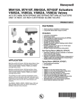
Download Arrow WV108-A Product data
Transcript
V5852A/V5853A/V5862A/V5863A
Small Linear Valves
PRODUCT DATA
FEATURES
GENERAL
The V5852A/V5853A/V5862A/V5863A Valves control hot and/or
chilled water for VAV terminal units, fan coil units, small reheaters and
recoolers in electric/electronic temperature control systems. The
valves are used with the M6410 Small Individual Room Controller
(IRC) 3-position floating Electronic Linear Valve Actuator, M7410
selectable 0 to 10 Vdc or 2 to 10 Vdc Electronic Actuator, or MP958
Pneumatic Valve Actuator.
•
V5852A is a two-way female sweat valve.
•
V5853A is a three-way female sweat mixing valve.
•
V5862A is a two-way female NPT valve.
•
V5863A is a three-way female NPT mixing valve.
•
Long stroke allows wider range of control.
•
Soft valve seat provides low leakage rate.
•
Valve inserts are changeable without draining valve when
used with the insert replacement tool.
•
Brass body and stainless steel stem.
•
Threaded plastic cover/manual handle allows manual
operation.
•
Easily installed in areas where space is limited.
•
No tool required for mounting M6410, M7410 or MP958
Actuators.
Contents
General ..........................................................................................
Features .........................................................................................
Specifications .................................................................................
Ordering Information ......................................................................
Installation ......................................................................................
Checkout ........................................................................................
Operation .......................................................................................
Copyright © 1995 Honeywell Inc. • All Rights Reserved
1
1
2
2
3
4
4
63-2496-1
V5852A/V5853A/V5862A/V5863A SMALL LINEAR VALVES
Models:
V5852A*, V5853A*, V5862A and V5863A Small Linear Valves for
control of hot and/or chilled water for VAV terminal units, fan coil units,
small reheaters and recoolers in electric/electronic temperature
control systems. V5852A and V5853A are sweat valves; V5862A and
V5863A are NPT valves. See Fig. 1.
V5852A and V5862A: Two-way valves.
V5853A and V5863A: Three-way mixing valves.
SPECIFICATIONS
IMPORTANT
The specifications given in this publication do not include
normal manufacturing tolerances. Therefore, an individual
unit may not exactly match the listed specifications. Also, this
product is tested and calibrated under closely controlled
conditions and some minor differences in performance can
be expected when those conditions are changed.
1/4
(6.5)
V5852/V5862
* Complete valve body soldering (V5852, V5853) before installing
cartridge inserts.
1-3/16
(30)
FLOW DIAGRAM
STROKE
23/32
(18)
C
INLET
B
B
D
A
PIPE SIZE
B
C
D (NPT)
D (SWEAT)
1/2 (13)
3 (77)
3/4 (19)
1-5/16 (34)
1/2 (13)
5/8 (16)
3/4 (19)
3-1/2 (88)
1 (25)
1-1/4 (32)
3/4 (19)
7/8 (22)
A
1/4
(6.5)
V5853/V5863
OUTLET
1-3/16
(30)
STROKE
FLOW DIAGRAM
23/32
(18)
D
PORT AB
PORT A
B
B
E
C
PORT B
B
A
PIPE SIZE
A
B
C
D
E (NPT)
E (SWEAT)
1/2 (13)
3 (77)
3/4 (19)
1-5/16 (34)
1-5/16 (34)
1/2 (13)
5/8 (16)
3/4 (19)
3-1/2 (88)
1 (25)
1-1/2 (38)
1-1/4 (32)
3/4 (19)
7/8 (22)
M7559
NOTE: SOLDER ENDS CONFORM TO ANSI B16-18.
Fig. 1. Dimensions of V5852A, V5853A, V5862A and V5863A in in. (mm).
ORDERING INFORMATION
When purchasing replacement and modernization products from your TRADELINE® wholesaler or distributor, refer to the TRADELINE Catalog
or price sheets for complete ordering number, or specify—
1. Model number.
2. Application.
3. Replacement parts required.
If you have additional questions, need further information, or would like to comment on our products or services, please write or phone:
1. Your local Honeywell Home and Building Control Sales Office (check white pages of your phone directory).
2. Home and Building Control Customer Logistics
Honeywell Inc., 1885 Douglas Drive North
Minneapolis, Minnesota 55422-4386
In Canada—Honeywell Limited/Limitée, 35 Dynamic Drive, Scarborough, Ontario M1V 4Z9. International Sales and Service offices in all
principal cities of the world. Manufacturing in Australia, Canada, Finland, France, Germany, Japan, Mexico, Netherlands, Spain, Taiwan, United
Kingdom, U.S.A.
63-2496—1
2
V5852A/V5853A/V5862A/V5863A SMALL LINEAR VALVES
Suitable Medium: Water with maximum 50% glycol.
Close-Off Rating: See actuator specifications for close-off ratings.
Controlled Water Temperature: 36°F to 230°F (2°C to 110°C).
Body Material:
Red Brass: 1/2 in., three-way.
3/4 in., two- and three-way.
Yellow Brass: 1/2 in., two-way.
Stroke: 1/4 in. (6.5 mm).
Flow Characteristic:
V5853 and V5863: Equal Percentage: A —> AB.
Linear: B —> AB.
V5852 and V5862: Equal percentage: A —> B.
Stem and Plug Assembly:
Stem: Stainless steel.
Plug: Brass.
Rangeability:
Two-way Valve: 50:1.
Three-way Valve: 50:1 for controlled port (A —> AB).
Dimensions: Valves: See Fig. 1.
Actuator Required:
M6410 Small Individual Room Controller (3 position floating).
M7410 0 to 10 Vdc or 2 to 10 Vdc Electronic Actuator, or
MP958 Pneumatic Valve Actuator.
Leakage Rate: <0.02% of Cv.
Valve Cv Rating: See Table 1.
NOTE:
Accessories and Replacement Parts:
WV108 Insert Replacement Tool, for replacing cartridge insert
without draining system.
WV108B Brush Tool for valve seat cleaning (used with WV108 tool).
Valve inserts are provided as spare parts. See Table 2.
Table 1. Valve Cv Ratings.
The Cv for the bypass port (B) on all three-way valves is
reduced by one Cv level; eg, A Port Cv = 0.47; B Port Cv =
0.29. This feature eliminates the need for a balancing valve
when the load is matched with the proper Cv.
Pipe Size in in. (mm)
1/2 (13)
Cv
.19
1/2 (13)
.29
1/2 (13)
.47
1/2 (13)
To determine the capacity index (Cv) needed for your application, use
the following formula:
Cv = gallons per minute divided by the square root of the
pressure drop across the valve when the valve is fully
open.
.74
1/2 (13)
1.2
1/2 (13)
1.9
3/4 (19)
2.9
3/4 (19)
4.9
Table 2. Valve insert replacement parts.
NOTE:
a
b
All inserts are used with either pneumatic or electronic actuators unless otherwise noted.
Part Number
Diameter (in.)
Interchangeable With
1/2
Cv
0.19
For
0901513
V5852A/V5862A
0901510, 511, 512
0901512
1/2
0.29
V5852A/V5862A
0901510, 511, 513
0901511
1/2
0.47
V5852A/V5862A
0901510, 512, 513
0901510
1/2
0.74
V5852A/V5862A
0901511, 512, 513
0901509
1/2
1.20
V5852A/V5862A
0901508
0901508
1/2
1.90
V5852A/V5862A
0901509
0901560
3/4
2.90
V5852A/V5862A
0901561
0901561
3/4
4.90
V5852A/V5862A
0901560
0901618
1/2
0.29
V5853A/V5863A
0901619, 620
0901619
1/2
0.47
V5853A/V5863A
0901618, 620
0901620
1/2
0.74
V5853A/V5863A
0901618, 619
0901621
1/2
1.20
V5853A/V5863A
None
0901622
1/2
1.90
V5853A/V5863A
None
0901623 a
3/4
2.90
V5853A/V5863A
0901624
0901624 a
3/4
4.90
V5853A/V5863A
0901623
0901506 b
3/4
2.90
V5853A/V5863A
0901507
0901507 b
3/4
4.90
V5853A/V5863A
0901506
These inserts for use only with 3/4 in., three-way pneumatic valve actuators.
These inserts for use only with 3/4 in., three-way electric/electronic valve actuators.
INSTALLATION
When Installing this Product…
� Read these instructions carefully. Failure to follow them could
damage the equipment or cause a hazardous condition.
� Check the ratings in the Specification section to make sure the
product is suitable for your application.
� Installer must be a trained, experienced service technician.
� After installation is complete, check out the product operation
as provided in these instructions.
3
63-2496—1
V5852A/V5853A/V5862A/V5863A SMALL LINEAR VALVES
NOTE:
CAUTION
1. Disconnect power supply before beginning installation to
prevent electrical shock and equipment damage.
2. Release system pressure to the valve body before
changing cartridge.
3. Install insert in V5852/V5853 sweat valves only after
soldering.
Actuator must commission itself at initial startup. See
M6410/M7410/MP958 specifications for details.
OPERATION
The actuator pushes the center stem of the valve down, compressing
the valve spring and closing the valve. When the actuator reverses,
the valve spring expands, opening the valve and pushing the center
stem up.
IMPORTANT
• When installing the valves, make sure the flow direction is
correct by checking the arrow on the valve body. Do not
mount the valve with the stem pointing downward. Leave the
protective cover in place until ready to attach the actuator.
• Before installing the valve and actuator, use the protective
cover/manual handle to make sure that the valve stem
operates freely. Impaired stem operation may indicate that
the stem was bent by rough handling. This condition may
require replacing the valve.
Location
The valves are supplied with a threaded plastic protective cover/
manual handle to protect the stem and to allow for manual operation.
Turning the protective cover/manual handle clockwise pushes the
center stem of the valve down, compressing the valve spring and
closing the valve. Turning the protective cover/manual handle
counterclockwise allows the spring to expand, opening the valve and
pushing the center stem up.
Use the protective cover/manual handle to fill the system during initial
installation. You can also use the protective cover/handle for heating/
cooling without a controller or actuator during the construction phase
of the building.
Select a location where the valve and actuator are accessible.
NOTE:
IMPORTANT
Mount all valve types in the return flow. When the delta
p-values exceed 8.70 psi (60 kPa), noise can develop.
Two-way valves
Do not discard the protective cover. It may be needed for
future manual operation.
In the two-way valves, the direction of flow is always from inlet port to
outlet port as indicated by the arrows on the valve body (see Fig. 2).
Mounting
The valve body should be completely installed in the pipe line before
the actuator is installed.
1. Verify pipe size and flow direction for the valve being used.
2. Position the valve so that the actuator can be easily installed.
3. Install the valve using the applicable tools and supplies
(wrenches, solder, flux, torch or soldering iron). Follow
standard practices.
4. Refer to the actuator instructions for installation of the actuator.
Three-way valves
Three-way valves are designed to be used as mixing valves. This
means that port AB is the total flow outlet; port A is the controlled flow
inlet; and port B is the bypass inlet (see Fig. 3).
IMPORTANT
The insert is packed separately from the V5852, V5853
sweat valve. The valve must be installed and soldered
before the insert is installed in the valve. Torque the insert
between 27 and 44 in.-lb.
INLET
INLET
+
–
OUTLET
+
–
OUTLET
CHECKOUT
M5357A
Check valve body and connections for leaks.
Fig. 2. Two-way valve operation block diagram
Before installing actuator, make sure that the valve stem operates
freely by using the protective cover/manual handle. Impaired stem
operation may indicate that the body was twisted by faulty piping or
that the stem was bent by rough handling. Either of these conditions
may require replacement of the valve or cartridge insert.
If leaking or other problems occur, remove pressure from the valve,
remove the cartridge insert, and make sure the cartridge insert Oring is properly seated and not damaged. Instructions for removing
and replacing the cartridge insert are packed with the WV108 Insert
Replacement Tool.
After installing the actuator, check the operation according to the
instructions provided with the actuator. Operating the system through
one complete cycle is recommended to verify that the valve and
actuator function properly.
Home and Building Control
Honeywell Inc.
1985 Douglas Drive North
Golden Valley, MN 55422
63-2496—1
G. H.
Rev. 9-95
AB
A
B
AB
A
+
–
B
M5358
Fig. 3. Three-way valve operation block diagram.
Home and Building Control
Honeywell Limited-Honeywell Limitée
740 Ellesmere Road
Scarborough, Ontario
M1P 2V9
Printed in U.S.A.
+
–
Printed on recycled paper containing at
least 4
10% post-consumer paper fibers.
Helping You Control Your World
www.honeywell.com/building/components


