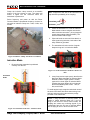
1
NaviTrack Brick
®
5 Watt Pipe and Cable Line
Transmitter
Operator’s
Manual
WARNING!
Read this operator’s manual
carefully before using this tool.
Failure to understand and follow
the contents of this manual may
result in electrical shock, fire
and/or serious personal injury.
NaviTrack Brick Line Transmitter
Table of Contents
GENERAL SAFETY INFORMATION ........................................................................................................................ 2
NAVITRACK BRICK COMPONENTS ...................................................................................................................... 5
KEYPAD AND DISPLAY............................................................................................................................................... 6
GETTING STARTED ................................................................................................................................................. 7
INSTALLING/CHANGING BATTERIES............................................................................................................................ 7
OPERATION TIME ..................................................................................................................................................... 7
POWERING UP / DOWN ............................................................................................................................................. 7
BATTERY CHECK ...................................................................................................................................................... 7
SOUNDS OF THE NAVITRACK BRICK TRANSMITTER..................................................................................................... 7
USING THE NAVITRACK BRICK LINE TRANSMITTER ........................................................................................ 8
DIRECT-CONNECT METHOD ...................................................................................................................................... 8
FCC LIMITS ........................................................................................................................................................... 10
USEFUL OPERATING TIPS ....................................................................................................................................... 10
INDUCTIVE CLAMP METHOD .................................................................................................................................... 10
INDUCTIVE MODE ................................................................................................................................................... 11
HIGH VOLTAGE INDICATOR...................................................................................................................................... 12
USEFUL INFORMATION ........................................................................................................................................ 12
RESISTANCE AND IMPEDANCE ................................................................................................................................. 13
USING HIGH AND LOW FREQUENCIES ...................................................................................................................... 13
TRANSPORTATION AND STORAGE ............................................................................................................................ 14
MAINTENANCE AND CLEANING ................................................................................................................................ 14
LOCATING FAULTY COMPONENTS............................................................................................................................ 14
SERVICE AND REPAIR ............................................................................................................................................. 14
TROUBLE SHOOTING GUIDE .................................................................................................................................... 15
SPECIFICATIONS ................................................................................................................................................... 16
DEFAULT SETTINGS ................................................................................................................................................ 16
STANDARD EQUIPMENT .......................................................................................................................................... 16
STANDARD REPLACEMENT PARTS ........................................................................................................................... 16
ii
www.navitrack.com
Ridge Tool Company ● Elyria, Ohio ● U.S.A
NaviTrack Brick Line Transmitter
®
NaviTrack Brick Line Transmitter
®
NaviTrack Brick Line Transmitter
Record the Serial Number of your unit below and retain for your records.
Serial
Number
Ridge Tool Company ● Elyria, Ohio ● U.S.A
www.navitrack.com
1
NaviTrack Brick Line Transmitter
General Safety Information
•
WARNING
Read and understand all instructions. Failure
to follow all instructions listed below may
result in electric shock, fire, and/or serious
personal injury
SAVE THESE INSTRUCTIONS!
Personal Safety
•
•
Work Area Safety
•
•
•
Keep your work area clean and well lit.
Cluttered benches and dark areas may cause
accidents.
Do not operate electrical devices or power
tools in explosive atmospheres, such as in
the presence of flammable liquids, gases, or
heavy dust. Electrical devices or power tools
create sparks which may ignite the dust or
fumes.
Keep bystanders, children, and visitors
away while operating tool. Distractions can
cause you to lose control.
•
•
•
Electrical Safety
•
•
•
Do not operate the system with electrical
components removed. Exposure to internal
parts increases the risk of injury.
Avoid exposure to rain or wet conditions.
Keep battery out of direct contact with water.
Water entering electrical devices increases the
risk of electric shock.
•
•
Avoid traffic. Pay close attention to moving
vehicles when using on or near roadways.
Wear visible clothing or reflector vests. Such
precautions may prevent serious injury.
Stay alert, watch what you are doing, and
use common sense. Do not use tool while
tired or under the influence of drugs, alcohol, or
medications. A moment of inattention while
operating tools may result in serious personal
injury.
Gloves should always be worn for health
and safety reasons. Sewer lines are
unsanitary and may contain harmful bacteria
and viruses.
Do not overreach. Keep proper footing and
balance at all times. Proper footing and
balance enables better control of the tool in
unexpected situations.
Use safety equipment. Always wear eye
protection. Dust mask, non-skid safety shoes,
hardhat, or hearing protection must be used for
appropriate conditions.
Use proper accessories. Do not place this
product on any unstable cart or surface. The
product may fall causing serious injury to a child
or adult, or causing serious damage to the
product.
Prevent object and liquid entry. Never spill
liquid of any kind on the product. Liquid
increases the risk of electrical shock and
damage to the product.
Battery Precautions
Line Transmitter Use and Care
•
•
•
2
Do not attach the leads to a high voltage
line.
Properly dispose of the batteries. Exposure
to high temperatures can cause the battery to
explode, so do not dispose of in a fire. Some
countries have regulations concerning battery
disposal.
Please
follow
all
applicable
regulations.
Use only the size and type of battery
specified. Do not mix cell types (e.g. do not
use alkaline with rechargeable). Do not use
partly discharged and fully charged cells
together (e.g. do not mix old and new).
Recharge batteries with charging units
specified by the battery manufacturer. Using
an improper charger can overheat and rupture
the battery.
www.navitrack.com
•
•
Use equipment only as directed. Do not
operate the transmitter unless proper training
has been completed and the owners manual
read.
Always transport the transmitter in the hard
case provided. This helps prevent product
damage due to shipping.
Do not immerse the antennas or case in
water. Store in a dry place. Such measures
Ridge Tool Company ● Elyria, Ohio ● U.S.A
NaviTrack Brick Line Transmitter
•
•
•
•
•
•
reduce the risk of electric shock and equipment
damage.
Store idle tools out of the reach of children
and other untrained persons. Tools are
dangerous in the hands of untrained users.
Maintain tools with care. Properly maintained
tools are less likely to cause injury.
Check for breakage of parts, and any other
conditions that may affect the transmitter’s
operation. If damaged, have the tool serviced
before using. Many accidents are caused by
poorly maintained tools.
Use only accessories that are recommended
by the manufacturer for your tool.
Accessories that may be suitable for one tool
may become hazardous when used on another
tool.
Keep handles dry and clean; free from oil
and grease. Allows for better control of the tool.
Protect against excessive heat. The product
should be situated away from heat sources
such as radiators, heat registers, stoves, or
other products (including amplifiers) that
produce heat.
Service
• Tool service
•
•
•
•
•
qualified service personnel under any of the
following conditions:
o If liquid has been spilled or objects have
fallen into product;
o If product does not operate normally by
following the operating instructions;
o If the product has been dropped or
damaged in any way;
o If the product exhibits a distinct change in
performance.
CAUTION
Remove batteries entirely before shipping.
If you have any questions regarding the service or
repair of this machine, call or write to:
Ridge Tool Company
Technical Service Department
400 Clark Street
Elyria, Ohio 44035-6001
Tel: (800) 519-3456
E-mail: [email protected]
www.ridgid.com
In any correspondence, please give all the
information shown on the nameplate of your tool,
including model number and serial number.
must be performed only by
qualified repair personnel. Service or
maintenance performed by unqualified repair
personnel could result in injury.
When servicing a tool, use only identical
replacement parts. Follow instructions in the
Maintenance Section of this manual. Use of
unauthorized parts or failure to follow
maintenance instructions may create a risk of
electrical shock or injury.
Follow
instructions
for
changing
accessories. Accidents are caused by poorly
maintained tools.
Provide proper cleaning. Remove battery
before cleaning. Do not use liquid cleaners or
aerosol cleaners. Use a damp cloth for
cleaning.
Conduct a safety check. Upon completion of
any service or repair of this product, ask the
service technician to perform safety checks to
determine that the product is in proper
operating condition.
Damage to the product that requires service.
Remove the batteries and refer servicing to
Ridge Tool Company ● Elyria, Ohio ● U.S.A
DANGER
Important Notice
The NaviTrack Brick is intended for use with a
NaviTrack locator/reciever. The locator is a
diagnostic tool that senses electromagnetic fields
emitted by objects underground. It is meant to aide
the user in locating these objects by recognizing
characteristics of the field lines and displaying them
on the screen. As electromagnetic field lines can be
distorted and interfered with, it is important to verify
the location of underground objects before digging.
Several utilities may be underground in the
same area. Be sure to follow local guidelines
and one-call service procedures.
Exposing the utility is the only way to verify its
existence, location, and depth.
Ridge Tool Co., its affiliates and suppliers, will
not be liable for any injury or any direct,
indirect, incidental, or consequential damages
sustained or incurred by reason of the use of
the NaviTrack Brick transmitter.
www.navitrack.com
3
NaviTrack Brick Line Transmitter
DANGER
ALWAYS HOOK UP LEADS FIRST BEFORE
POWERING THE UNIT ON TO AVOID SHOCK.
ALWAYS
TURN
UNIT
DISCONNECTING LEADS.
OFF
BEFORE
Note: The unit must be disconnected from any
external conductors before attempting to access
the battery case or change the batteries. The
NaviTrack Brick is protected by an interlock which
isolates the unit when the battery case is opened,
awareness
dictates
but
standard
safety
disconnecting the leads rather than relying solely
on this feature.
ELECTRIC SHOCK MAY RESULT FROM
FAILURE TO CONNECT LEADS BEFORE
POWERING THE UNIT ON.
Do not handle the transmitter while you are
connected directly to ground yourself.
Wear appropriate heavy soled footwear as you
would when working with any high-voltage
equipment.
Note: The line transmitter is normally powered by
internal batteries, and is designed to protect the
user from voltages up to 250 VAC that may be
accidentally encountered. Battery power is the sole
power option available on the NaviTrack Brick. The
High Voltage LED will light if the unit encounters
more than approximately 62 VAC (RMS).
WARNING
In compliance with Federal Standard EN-50249,
the ST-305 line transmitter is designed to
withstand up to 250 VAC 50/60 Hz excitation
between the two leads.
The user is cautioned not to deliberately
connect to live power lines. If the transmitter
indicates the presence of high voltage, use
high
voltage
precautions
to
carefully
disconnect the line transmitter from the high
voltage source.
4
www.navitrack.com
Ridge Tool Company ● Elyria, Ohio ● U.S.A
NaviTrack Brick Line Transmitter
NaviTrack Brick Components
Battery Case
Keypad
Frequency,
Mode and
Power LEDs
Connection
Leads and
Clips
Inductive Clamp Jack
Ground Stake
Battery Case
Figure 1: Components of the NaviTrack Brick
Ridge Tool Company ● Elyria, Ohio ● U.S.A
www.navitrack.com
5
NaviTrack Brick Line Transmitter
Keypad and Display
Frequency
Indicator
Power
Indicator
High Voltage
Warning
Power
On/Off /
Power
Selection
Induction
Mode
Indicator
Induction
Mode Toggle
Frequency
Selection
Figure 2: Keypad and Display
6
•
Frequency Indicator: Indicates frequency in use.
•
Power Indicator: Indicates the relative level of output power; displays
estimated battery power level on start-up.
•
Frequency/Mode Selection: Selects desired frequency; used to initiate
high-frequency mode.
•
Power On/Off: Used to power the NaviTrack Brick on and off, and to set
current level.
•
Induction Mode Toggle: Used to switch the NaviTrack Brick into
Inductive Mode.
•
Induction Mode Indicator: Illuminated when unit is in Inductive Mode.
•
High Voltage Warning: Warning light when high voltage is encountered
(> ~62V AC RMS).
www.navitrack.com
Ridge Tool Company ● Elyria, Ohio ● U.S.A
NaviTrack Brick Line Transmitter
Getting Started
Installing/Changing Batteries
To install batteries into the NaviTrack Brick line
transmitter, rotate the knob on the battery holder
counter-clockwise until the battery holder door
unscrews. Pull straight back on the knob to remove
the cover. Insert the 6 “C” batteries as shown on the
inside decals .
applications). Operation at low temperatures will also
reduce battery life.
Batteries often recover after being subjected to high
loads. If time is allowed, batteries may recover
enough to offer additional hours of operation.
Powering Up / Down
Turn the power ON by depressing the Power
key
on the keypad. The current frequency and powerlevel LEDs will light up. A beep will sound.
key
Power the unit OFF by depressing the Power
on the keypad for 2 seconds. Three tones will sound.
Automatic Shut Down
To save energy, the NaviTrack Brick will
automatically shutdown after an interval which varies
with the power setting:
Low Power
4 hours
Medium Power 2 hours
High Power
1 hour
Battery Check
Figure 3: Battery Orientation and Cover
Fit the cover into the case and push down firmly while
turning down the knob clockwise to close. Ensure the
cover is firmly screwed into place.
Note: When replacing batteries use 6 C cells that
are the same type. Do not mix Alkaline with NiCd
(NiCad or Nickel Cadmium) for example. Be sure
to replace with batteries where all of the cells have
the same amount of charge. Do not use half used
alkalines with brand new.
At start-up, the Brick will check available power and
will indicate estimated battery levels by lighting one,
two, or three LEDs in the right hand column (power
level) on the control panel. One LED indicates low
batteries, two indicates medium charge, and three
LEDs indicates full battery charge is available. These
levels are only estimates based on a rapid internal
check. A rapid series of beeps will sound if the
battery levels run low in operation.
Sounds of the NaviTrack Brick
Transmitter
Sounds are associated with specific events.
CAUTION
Always remove batteries entirely before
shipping the Brick.
Operation Time
Typical operation time varies for the Brick line
transmitter, depending on factors such as load, and
current transmitted. Other factors that affect the
operation time will include chemistry of the battery
(many of the new high performance batteries, such
as the “Duracell ® ULTRA” last 10%-20% longer than
conventional alkaline cells under high demand
Ridge Tool Company ● Elyria, Ohio ● U.S.A
They include:
•
Beeps – Beeps when current is flowing; rate
increases with current increase.
•
Beeps – Turn ON (4 beeps)/OFF (3 beeps).
•
Short Double Tone – Inductive Clamp
connected.
•
Long-Short-Short Tone – Inductive Mode.
•
Rapid series of beeps – Low Battery Warning
The sound may be toggled on or off by pressing the
Frequency and Power buttons simultaneously.
www.navitrack.com
7
NaviTrack Brick Line Transmitter
Using the NaviTrack Brick Line
Transmitter
The NaviTrack Brick transmitter is part of Ridgid’s
NaviTrack cable and pipe locating system. The
NaviTrack Brick is used to energize a pipe or line with
an “active” electrical signal, so that the underground
line may be traced with a compatible receiver (such
as the NaviTrack II). This allows the line’s location to
be correctly marked so it can be exposed for repair
or avoided during excavation.
The NaviTrack Brick line transmitter can apply an
active tracing signal to a target conductor in three
ways:
Direct Connect – The transmitter’s leads are
connected directly to the target conductor and a
suitable ground.
Figure 4: Connecting the Ground Stake
2. Connect the other lead to the target
conductor.
Inductive Clamp – The jaws of the inductive clamp
encircle the target conductor; there is no metal-tometal contact. The inductive clamp is connected to
the transmitter via the jack at the transmitter’s right
end. (The inductive clamp is an optional accessory.
See page 10).
Inductive Mode (internal coils) – the transmitter is
placed over, and in-line with, a conductor. Its internal
antenna broadcasts a signal to the target conductor
below ground, inducing a current into the target
conductor. See page 11.
DANGER
Always connect leads before turning the
transmitter on to avoid electrical shock. Ensure
transmitter is well grounded.
Figure 5: Connecting to a Line
Direct-Connect Method
1. Attach the NaviTrack Brick line
transmitter to ground and to the target
line.
Remove the ground spike from the right end of the
unit and insert it into the ground. Connect one of the
cable leads to the grounding spike. The leads are
universal, so either may be used for the ground.
Figure 6: Alternative Connection Method
8
www.navitrack.com
Ridge Tool Company ● Elyria, Ohio ● U.S.A
NaviTrack Brick Line Transmitter
WARNING
NEVER CONNECT TO LINES KNOWN TO BE
ENERGIZED
WITH
A
POTENTIALLY
DANGEROUS ELECTRICAL CURRENT. To
increase safety, the ground lead should be
attached first. If there were an unknown high
voltage running through the target line, this would
allow a means of redirecting the current away from
the transmitter and operator.
Note: Installations which use plastic pipes will
typically have a trace wire installed along the pipe
for tracing purposes. Simply clip the transmitter
lead to the trace wire.
Figure 7: NaviTrack Brick Showing 8kHz, Medium
Power
Power the NaviTrack Brick up by pressing the Power
Key. A multiple tone will sound on powering up. After
a short silence, the unit will begin beeping regularly,
indicating current is flowing.
To set the unit on 262 kHz, press the Frequency Key
four times in a rapid succession. The 33 kHz LED will
flash rapidly to indicate that the 262 kHz (European
version: 93 kHz) frequency has been set.
3. Select a Frequency on the Brick.
The NaviTrack Brick line transmitter offers four
choices of frequency. Frequency is chosen by
pressing on the Frequency Select key which will light
the LEDs in sequence.
Available frequencies are:
4. Check the Circuit and Adjust Power
Level
Confirm the circuit is grounded by ensuring that the
connection to the ground stake is secure and the
stake is firmly embedded in the ground. To adjust the
power level, press the power button briefly. The Brick
will cycle through the low, medium, and high power
levels.
1kHz
8kHz
33 kHz
262 kHz
European version: 93 kHz (93,623 Hz.)
Note – Higher power settings produce more
current, which gives a stronger signal. Less current
prolongs battery life. Signal strength measured by
the receiver is directly proportional to the amount
of current on the line. More current will produce a
stronger signal received by the receiver.
Use only as much current as is needed to get a
strong reading on the receiver.
Ridge Tool Company ● Elyria, Ohio ● U.S.A
www.navitrack.com
9
NaviTrack Brick Line Transmitter
•
Power Settings
There are 3 power settings that the user can choose
from:
•
Low power (approximately .5 watt)
•
Medium power (approximately 1.5 watts)
•
High power (approximately 5 watts)
•
Low power will provide the least current with the
longest battery life. Actual power output will vary with
circuit resistance and frequency used. These values
assume a nominal 320-ohm load.
CAUTION
If the transmitter is producing low or no current due
to poor circuit conditions, the signal may be too
low to be detected by the receiver locator and
inadequate for tracing.
5. Check the Receiver.
Confirm that the transmitter and receiver are set to
the same frequency. Hold the receiver near the
transmitter cables and confirm a signal is being
received.
•
A good ground has lower resistance, which
allows more current and a stronger signal. For a
better connection to ground, insert the
grounding spike as far as possible. Moist
ground is a better conductor than dry soil, so try
wetting the area if necessary.
The transmitter’s leads can act as antennas,
broadcasting a strong signal. If locating close to
the transmitter, keep the leads short by stowing
the excess length on the transmitter’s body.
This will reduce the amount of interfering
signals from the leads. Where possible, place
the transmitter away from the area of the
intended locate. This is especially true in
Inductive Mode, to avoid coupling through the
air with the receiver.
Start by using the lowest frequency and the
least amount of current needed to effectively
illuminate the line. Lower frequencies travel
farther because they do not dissipate as
quickly. Higher frequencies generally make it
easier to illuminate a line, but they don’t travel
as far. They are much more likely to couple
onto other utility lines, distorting the signal and
reducing the accuracy.
Inductive Clamp Method
FCC Limits
47 CFR 15.213 requires that from 9kHz up to (but not
including) 45kHz, peak output power shall not exceed
10W. From 45kHz to 490kHz, it must not exceed 1W.
When the ST-305 is set to 262 kHz (European
version: 93 khz), the power output levels are limited:
Low:
Medium:
High:
0.3 watt
0.6 watt
1 watt
These values assume a nominal load of 320 ohms.
Useful Operating Tips
• The lower the resistance, the more current will
be put on the line. A good circuit is one that
allows enough current to flow so that the locator
gets a solid, clear signal.
•
10
To help lower the resistance of the circuit,
scrape away dirt, paint, and corrosion before
connecting to the target conductor or to the
grounding spike.
www.navitrack.com
Figure 8: NaviTrack Brick with Inductive Clamp
When using an inductive clamp, plug the inductive
clamp jack into the receptacle provided at the end of
the transmitter. The induction-mode LED will flash
when a clamp is connected. Note that for a clear
signal using an inductive clamp, both ends of the
utility should be grounded.
Ridge Tool Company ● Elyria, Ohio ● U.S.A
NaviTrack Brick Line Transmitter
Clamp the inductive clamp around an accessible
portion of the line chosen to trace. The clamp will
induce a signal into the conductor when the
transmitter is powered on.
Select frequency and power as with the Direct
Connect Method. Operational frequency choices for
use with an Inductive Clamp are 1 kHz, 8 kHz, and
33 kHz.
Note: A slight tilt to the axis of the conductor can
help reduce the probability of air-coupling:
Transmitter
Conductor
2. Power the transmitter on. Push the Inductive
Mode switch to induce a signal onto the line
without a direct connection. (A long beep will
sound when entering Inductive Mode.) The
Inductive Mode LED will light .
3. Clips and leads are not used. Note that for a
clear signal using induction, both ends of the
utility should be grounded.
4. The transmitter will emit a series of regular
beeps as long as it is in Inductive Mode.
Figure 9: Inductive Clamp Attached to a Conductor
Inductive Mode
1. Be sure that the transmitter is positioned
correctly over the line.
Figure 11: NaviTrack Brick in Inductive Mode at 33
kHz
Orientation
Guide
5. Lower frequencies couple poorly; therefore the
NaviTrack Brick transmitter in Inductive Mode
defaults to 33KHz. Higher power is usually
required for a clear signal in Inductive Mode.
Pressing the power button will cycle through
the three available power levels: 1 kHz, 8
kHz, and 33 kHz.
To avoid tangled cords, wrap the cords back around
the ends of the NaviTrack Brick when storing, lead
end last, and secure the ends under the prongs
provided on the transmitter.
Figure 10: Orientation to the Line – Inductive Mode
Ridge Tool Company ● Elyria, Ohio ● U.S.A
NOTE: If using the Brick in Inductive Mode, be
certain to switch Inductive Mode off if you are
going to use the unit in direct connect mode. Air
coupling can create very confusing signals if you
inadvertently have the unit set to Inductive Mode
and are trying to use it in direct connect mode.
www.navitrack.com
11
NaviTrack Brick Line Transmitter
Coupling through Air
When a line transmitter is set to Inductive Mode, it
energizes a wire or pipe under it by emitting a pulse
of energy at the selected frequency. This pulse
forms an electromagnetic field which induces a
current into the conductor (the pipe or wire)
underneath it. The field builds and collapses at the
frequency at which the pulse is generated by the
transmitter.
A secondary field is set up around the pipe or wire by
the current induced into it. This secondary field is
normally round in shape, just as it would be if you
connected the transmitter directly. But the primary
field from the transmitter, which does the inducing, is
not round, and is not the same as the field set up on
the pipe or wire.
The field generated by the transmitter in Inductive
Mode has a shape something like a football. When
the transmitter is sitting on the ground, roughly half of
that field extends below it. The ends of the “football”
extend out past the central axis of the transmitter in
the same direction as the pipe or wire under it.
Note: The inductor core of the ST-305 emits the
signal when the unit is transmitting in Inductive
Mode. A hard hit or a drop could possibly damage
the core. To test that the core is intact using a
SeekTech SR-20 receiver:
1.
Power transmitter on.
2.
Set frequency output to 33kHz.
3.
Set power level to high power.
4.
Power receiver on.
5.
Set to receive 33kHz.
6.
Move receiver 12 inches from transmitter.
If the inductor core is undamaged, the receiver
should show a Signal Strength reading larger than
2000.
High Voltage Indicator
Whenever the line transmitter encounters voltage
higher than 62 VAC, it will flash a red LED at the top
of the keypad. Should this occur carefully disconnect
the transmitter using high-voltage precautions.
Figure 12: Air-Coupling in Inductive Mode
Near the transmitter, the receiver reads on the
local dipole field around the transmitter.
If the receiver is within this field, it will read clearly
and well on the transmitter, rather than on the pipe or
wire being traced. The transmitter and the receiver
will couple through the air for a limited distance
around the transmitter. This problem does not occur
with direct coupling, and is not important when using
an inductive clamp. But it can be an issue when using
the transmitter in purely Inductive Mode (i.e., without
a clamp.)
It is important to set up the transmitter, when using
the Inductive Mode, a good 30 feet (10m) away from
the region where tracing occurs, and to be aware of
the difference between the transmitter’s field and the
induced field being traced. They will both have the
same frequency, but the transmitter’s field is limited
to the region around the transmitter itself.
12
www.navitrack.com
Figure 13: High Voltage Warning LED
Ridge Tool Company ● Elyria, Ohio ● U.S.A
NaviTrack Brick Line Transmitter
Useful Information
Resistance and Impedance
A circuit has a certain amount of resistance to
current; this is measured in ohms. (Ω) Higher
resistance reduces the amount of current that can be
put on an underground line. Factors that affect
resistance in the transmitter circuit are conductivity of
the line itself, breaks or faults in the line, insulation
problems with the line, and how well the transmitter is
grounded. (Poor grounding makes the return path of
the circuit more resistive).
Grounding can be affected by soil conditions, length
of grounding rod, or how the line transmitter is
connected to the grounding rod. Good grounding
improves your signal by reducing the total resistance
the transmitter encounters.
Impedance is a form of resistance which is caused by
a back-force in the electrical field caused by
alternating current (AC). Impedance can be thought
of as “AC resistance”, and adds to the resistance in
the circuit in proportion to the frequency being used
(i.e., higher AC frequencies add more impedance
than lower ones).
Using High and Low Frequencies
Understanding the behaviour of different frequencies
under different conditions can be important in doing
effective and accurate locates.
In both direct-connect and Inductive Mode, the Brick
is essentially doing the same thing – imposing a
wave of traceable energy onto the target pipe or line.
This electrical energy rises and falls a certain number
of times per second, which in turn causes a magnetic
field to build and collapse around the conductor at a
regular rate. This rate is known as the frequency of
the generated current and of its consequent magnetic
field.
conductor than a high frequency will. Secondly, lower
frequency fields lose less energy to the area around
the conductor. If you can get a clear signal on your
receiver using a low frequency it is generally
preferable, because you will be able to trace it further
and it will tend to confine itself to the original
conductor more than a high-frequency signal will. But
a low-frequency signal is more likely to be interrupted
by gaps in the line or poor insulation, or hidden by
other magnetic fields in the area. It is a “weaker”
signal in that respect. While it doesn’t jump as readily
onto other lines, it will dissipate if traveling on a line
with poor insulation, bare-concentric cable, or bare
pipe exposed to earth, and will follow the path of least
resistance, which is not always the path intended by
the operator. This can make tracing the original
conductor difficult.
High Frequencies
The Brick will generate frequencies as high as 262
kilohertz. (European versions are limited to 93 kHz.)
There are certain conditions where only higher
frequencies will serve. High-frequency signals are
especially valuable when you are tracing a line that
has some sort of interruption—such as a gasket, or
decayed insulation – in the continuity of the
conductor. The reason is that a high-frequency signal
can “jump” some barriers and continue without
dissipating as much signal as a lower frequency
would.
A high-frequency signal can also be valuable in
getting a signal on a receiver when there is a poorly
grounded circuit, compared to the signal the same
receiver will detect at a lower frequency. While all
currents tend to follow the path of least resistance, a
high-frequency current will “buck” this tendency to
some degree, reaching across incidental barriers.
Low Frequencies
The disadvantage to higher frequencies is that they
also jump onto other conductors. If you have two
wires side by side in a trench, a higher frequency
used to trace one of them may illuminate both of
them. Additionally, nearby metallic objects, or even
highly metalized soil, may pick up a higher frequency
and distort the picture at the locator. If a gas line is
being “illuminated” with a high frequency current, it
may bleed over onto a water line or a power cable
running nearby, confusing the picture of where the
original line is.
The Brick will generate frequencies as low as 1
kilohertz. Low frequencies are especially useful for
several reasons. First, they will travel farther at a
detectable level along a continuous pipe or wire
As a general rule, detecting with lower frequencies is
more reliable for the reasons given above, IF you can
get a good signal.
Frequency is expressed in terms of hertz, which
means cycles per second, or kilohertz, thousands of
cycles per second.
Ridge Tool Company ● Elyria, Ohio ● U.S.A
www.navitrack.com
13
NaviTrack Brick Line Transmitter
Transportation and Storage
If you have any questions regarding the service or
repair of this machine, call or write to:
To avoid tangled cords, wrap the cords back around
the ends of the Brick when storing, lead end last, and
secure the ends under the prongs provided on the
transmitter.
Ridge Tool Company
Technical Service Department
400 Clark Street
Elyria, Ohio 44035-6001
Tel: (800) 519-3456
E-mail: [email protected]
Before transporting make sure that the unit is turned
OFF to preserve battery power.
Also make sure that the NaviTrack Brick line
transmitter is secure and does not bounce around or
get bumped by loose equipment.
For the name and address of your nearest
Independent Authorized Service Center, contact the
Ridge Tool Company at (800) 519-3456 or
http://www.ridgid.com.
CAUTION
Always remove batteries entirely before
shipping the NaviTrack Brick.
The NaviTrack Brick line transmitter should be stored
in a cool dry place.
Note: If storing the NaviTrack Brick line transmitter
for an extended period of time, the batteries should
be removed.
Maintenance and Cleaning
1. Keep the NaviTrack Brick line transmitter
clean with a damp cloth and some mild
detergent. Do not immerse in water.
2. When cleaning, do not use scraping tools or
abrasives as they may permanently scratch
the display. NEVER USE SOLVENTS to clean
any part of the system. Substances like
acetone and other harsh chemicals can cause
cracking of the case.
Locating Faulty Components
For troubleshooting suggestions, please refer to the
trouble shooting guide at the end of the manual. If
necessary, contact NaviTrack Technical Service at
866-733-5832.
Service and Repair
Tool should be taken to a RIDGID Independent
Authorized Service Center or returned to the factory.
All repairs made by Ridge service facilities are
warranted against defects in material and
workmanship.
14
www.navitrack.com
Ridge Tool Company ● Elyria, Ohio ● U.S.A
NaviTrack Brick Line Transmitter
Trouble Shooting Guide
PROBLEM
REMEDY
LEDs appear completely
dark,
or
completely light when
unit is ON.
Try Powering the unit OFF and then back ON.
Allow the unit to cool if it has been exposed to excessive heat from sunlight.
Check that the correct frequency has been selected on both units. (See manual for the
specific receiver.) Higher or lower frequencies may be tried.
Check to make sure that the receiver and the line transmitter are in the same mode.
Receiver will not pick
up the line transmitter’s signal.
Make sure that the proper functions are activated on the receiver. e.g. activating the line
trace function for line tracing.(See manual for the receiver.)
Adjust power upward if possible.
Ensure grounding is adequate.
If using inductive mode, check for core damage using the test on page 12.
Check orientation of batteries.
Unit will not turn ON.
Check that the batteries are fresh or charged.
Check to see that the battery contacts are OK.
93 kHz
received
signal
not
Check that receiver is set to the actual 93kHz freguency of 93,696 Hz. Some receivers
use a different frequency for 93 kHz (93,622.9). Update locator software.
Ridge Tool Company ● Elyria, Ohio ● U.S.A
www.navitrack.com
15
NaviTrack Brick Line Transmitter
Specifications
Standard Equipment
Weight:
1.6 lbs (.772 Kg) w/o batteries, 2.5 lbs.(1.1 Kg)
w/batteries.
Dimensions:
Depth ..................... 4.7” (11.9 cm)
Width ..................... 7.75” (19.6 cm)
Height .................... 3” (7.6 cm)
Power Source:
6 Alkaline or rechargeable batteries.(C-Cells).
Power Settings:
25 mA to 5W.
Output Power:
Nominal 5 watts.
Item
NaviTrack Brick Transmitter
Direct connect leads w/ clips
Operator’s Manual
6 C-cell batteries (Alkaline)
Cat. #
20168
22753
None
None
Standard Replacement Parts
Ground Spike
Alligator Clip
Cable
Battery Holder Cover Assembly
22528
18443
22743
22748
Default Settings
42V Maximum (RMS).
1 kHz, 8kHz, 33 kHz selectable.
16
www.navitrack.com
Ridge Tool Company ● Elyria, Ohio ● U.S.A
NaviTrack Brick Line Transmitter
Notes
Ridge Tool Company ● Elyria, Ohio ● U.S.A
www.navitrack.com
17
What is covered
RIDGID® tools are warranted to be free of defects in workmanship and material.
How long coverage lasts
This warranty lasts for the lifetime of the RIDGID® tool. Warranty coverage ends when the product becomes
unusable for reasons other than defects in workmanship or material.
How you can get service
To obtain the benefit of this warranty, deliver via prepaid transportation the complete product to RIDGE TOOL
COMPANY, Elyria, Ohio, or any authorized RIDGID® INDEPENDENT SERVICE CENTER. Pipe wrenches and
other hand tools should be returned to the place of purchase.
What we will do to correct problems
Warranted products will be repaired or replaced, at RIDGE TOOL’S option, and returned at no charge; or, if after
three attempts to repair or replace during the warranty period the product is still defective, you can elect to receive a
full refund of your purchase price.
What is not covered
Failures due to misuse, abuse or normal wear and tear are not covered by this warranty. RIDGE TOOL shall not be
responsible for any incidental or consequential damages.
How local law relates to the warranty
Some states do not allow the exclusion or limitation of incidental or consequential damages, so the above limitation
or exclusion may not apply to you. This warranty gives you specific rights, and you may also have other rights,
which vary, from state to state, province to province, or country to country.
No other express warranty applies
This FULL LIFETIME WARRANTY is the sole and exclusive warranty for RIDGID® products. No employee, agent,
dealer, or other person is authorized to alter this warranty or make any other warranty on behalf of the RIDGE
TOOL COMPANY.
Ridge Tool Company
400 Clark Street
Elyria, Ohio 44036-2023
Part Number :
999-999-416.10
748-025-604-0B-P3
Rev.C
11/2011