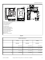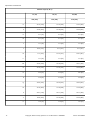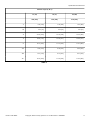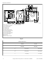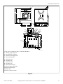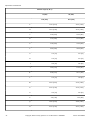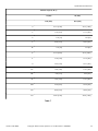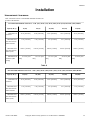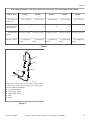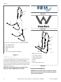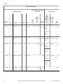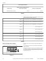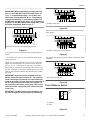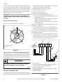
1
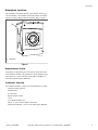
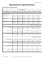
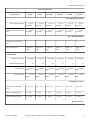
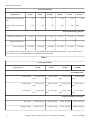
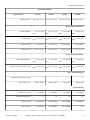
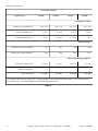
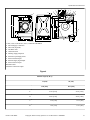
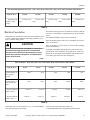
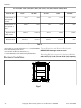
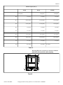
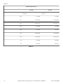
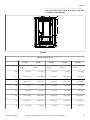
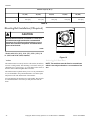
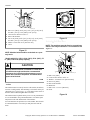
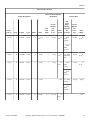
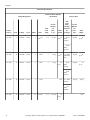
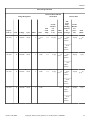
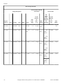
Cabinet Hardmount
Refer to Page 5 for Model Identification
Installation
Washer-Extractors
CFD796N_SVG
Original Instructions
Keep These Instructions for Future Reference.
(If this machine changes ownership, this manual must accompany machine.)
www.alliancelaundry.com
Part No. D1341ENR8
May 2014
Table of Contents
Safety Information..................................................................................5
Explanation of Safety Messages....................................................................... 5
Important Safety Instructions........................................................................... 5
Safety Decals................................................................................................. 6
Introduction........................................................................................... 7
Model Identification........................................................................................7
Nameplate Location........................................................................................ 9
Replacement Parts.......................................................................................... 9
Customer Service............................................................................................9
Specifications and Dimensions.............................................................. 10
Specifications and Dimensions.......................................................................10
Installation........................................................................................... 30
Dimensional Clearances................................................................................ 30
Machine Foundation......................................................................................31
Mechanical Installation..................................................................................32
Frame Dimensions and Mounting Bolt Location...........................................32
Mounting Bolt Installation (If Required)......................................................... 36
Models with 14 lb. (65 l), 18 lb. (75 l), 25 lb. (100 l), 30 lb. (135 l) and 35 lb.
(165 l) Capacity..................................................................................... 36
Models with 33 lb. (150 l), 40 lb. (185 l), 55 lb. (235 l), 75 lb. (305 l) and 90 lb.
(400 l) Capacity..................................................................................... 38
Drain Connection..........................................................................................39
Water Connection......................................................................................... 42
WRAS Water Connection.......................................................................... 44
Electrical Installation.....................................................................................44
Electrical Connection.................................................................................... 58
Machine without Electric Heating............................................................... 58
Machine with Electric Heating....................................................................58
Remote Liquid Supply Connection................................................................. 58
Chemical Injection Supply System..............................................................59
Steam Requirements (Steam Heat Option Only)...............................................59
Supply Programming Table........................................................................ 60
Supply Relay Configuration (No Wiring).....................................................60
Primary 220 Volt Remote Liquid Supply Connection....................................61
Out-of-Balance Switch.................................................................................. 61
Automatic Lubricator.................................................................................... 62
Control Function Test....................................................................................62
© Copyright
2014, Alliance Laundry Systems LLC
All rights reserved. No part of the contents of this book may be reproduced or transmitted in any form or by any means without the expressed
written consent of the publisher.
Part No. D1341ENR8
© Copyright, Alliance Laundry Systems LLC - DO NOT COPY or TRANSMIT
3
Disposal of Unit.................................................................................... 63
4
© Copyright, Alliance Laundry Systems LLC - DO NOT COPY or TRANSMIT
Part No. D1341ENR8
Safety Information
Safety Information
Explanation of Safety Messages
•
Precautionary statements [“DANGER,” “WARNING,” and
“CAUTION”], followed by specific instructions, are found in this
manual and on machine decals. These precautions are intended
for the personal safety of the operator, user, servicer, and those
maintaining the machine.
•
DANGER
•
Indicates an imminently hazardous situation that, if
not avoided, will cause severe personal injury or
death.
WARNING
Indicates a hazardous situation that, if not avoided,
could cause severe personal injury or death.
•
CAUTION
Indicates a hazardous situation that, if not avoided,
may cause minor or moderate personal injury or
property damage.
Additional precautionary statements [“IMPORTANT” and
“NOTE”] are followed by specific instructions.
IMPORTANT: The word “IMPORTANT” is used to inform the reader of specific procedures where minor
machine damage will occur if the procedure is not followed.
NOTE: The word “NOTE” is used to communicate installation, operation, maintenance or servicing information that is important but not hazard related.
To reduce the risk of fire, electric shock, serious injury or death to persons when using your washer,
follow these basic precautions:
W023
Part No. D1341ENR8
•
•
WARNING
Read all instructions before using the washer.
•
•
Important Safety Instructions
•
•
•
Install the washer according the INSTALLATION instructions. Refer to the GROUNDING instructions in the INSTALLATION manual for the proper grounding of the washer. All connections for water, drain, electrical power and
grounding must comply with local codes and be made by licensed personnel when required. It is recommended that the
machine be installed by qualified technicians.
Do not install or store the washer where it will be exposed to
water and/or weather.
To prevent fire and explosion, keep the area around machine
free from flammable and combustible products. Do not add
the following substances or textiles containing traces of the
following substances to the wash water: gasoline, kerosene,
waxes, cooking oils, vegetable oils, machine oils, dry-cleaning solvents, flammable chemicals, thinners, or other flammable or explosive substances. These substances give off vapors
that could ignite, explode or cause the fabric to catch fire by
itself.
Under certain conditions, hydrogen gas may be produced in a
hot water system that has not been used for two weeks or
more. HYDROGEN GAS IS EXPLOSIVE. If the hot water
system has not been used for such a period, before using a
washing machine or combination washer-dryer, turn on all hot
water faucets and let the water flow from each for several minutes. This will release any accumulated hydrogen gas. The
gas is flammable, do not smoke or use an open flame during
this time.
To reduce the risk of an electric shock or fire, DO NOT use
an extension cord or an adapter to connect the washer to the
electrical power source.
Do not allow children to play on or in the washer. Close supervision of children is necessary when the washer is used
near children. This appliance is not intended for use by young
children or infirm persons without supervision. Young children should be supervised to ensure that they do not play with
the appliance. This is a safety rule for all appliances.
DO NOT reach and/or climb into the tub or onto the washer,
ESPECIALLY if the wash drum is moving. This is an imminently hazardous situation that, if not avoided, will cause severe personal injury or death.
Never operate the washer with any guards, panels and/or parts
removed or broken. DO NOT bypass any safety devices or
tamper with the controls.
Use washer only for its intended purpose, washing textiles.
Never wash machine parts or automotive parts in the machine. This could result in serious damage to the basket or
tub.
Use only low-sudsing, no-foaming types of commercial detergent. Be aware that hazardous chemicals may be present.
Wear hand and eye protection when adding detergents and
chemicals. Always read and follow manufacturer’s instructions on packages of laundry and cleaning aids. Heed all
© Copyright, Alliance Laundry Systems LLC - DO NOT COPY or TRANSMIT
5
Safety Information
warnings or precautions. To reduce the risk of poisoning or
chemical burns, keep them out of the reach of children at all
times [preferably in a locked cabinet].
Do not use fabric softeners or products to eliminate static unless recommended by the manufacturer of the fabric softener
or product.
Always follow the fabric care instructions supplied by the textile manufacturer.
Loading door MUST BE CLOSED any time the washer is to
fill, tumble or spin. DO NOT bypass the loading door switch
by permitting the washer to operate with the loading door
open. Do not attempt to open the door until the washer has
drained and all moving parts have stopped.
Be aware that hot water is used to flush the supply dispenser.
Avoid opening the dispenser lid while the machine is running.
Do not attach anything to the supply dispenser’s nozzles, if
applicable. The air gap must be maintained.
Do not operate the machine without the water reuse plug or
water reuse system in place, if applicable.
Be sure water connections have a shut-off valve and that fill
hose connections are tight. CLOSE the shut-off valves at the
end of each wash day.
Keep washer in good condition. Bumping or dropping the
washer can damage safety features. If this occurs, have washer checked by a qualified service person.
DANGER: Before inspecting or servicing machine, power
supply must be turned OFF. The servicer needs to wait for at
least 5 minutes after turning the power OFF and needs to
check for residual voltage with a voltage meter. The inverter
capacitor or EMC filter remains charged with high voltage for
some time after powering OFF. This is an imminently hazardous situation that, if not avoided, will cause severe personal
injury or death.
Do not repair or replace any part of the washer, or attempt any
servicing unless specifically recommended in the user-maintenance instructions or in published user-repair instructions
that the user understands and has the skills to carry out. ALWAYS disconnect the washer from electrical, power and water supplies before attempting any service.
Disconnect the power by turning off the circuit breaker or by
unplugging the machine. Replace worn power cords.
Before the washer is removed from service or discarded, remove the door to the washing compartment.
Failure to install, maintain, and/or operate this washer according to the manufacturer’s instructions may result in conditions
which can produce bodily injury and/or property damage.
•
•
•
•
•
•
•
•
•
•
•
•
•
WARNING
Machine installations must comply with minimum
specifications and requirements stated in the applicable Installation Manual, any applicable municipal
building codes, water supply requirements, electrical wiring regulations and any other relevant statutory regulations. Due to varied requirements and applicable local codes, this machine must be installed,
adjusted, and serviced by qualified maintenance personnel familiar with applicable local codes and the
construction and operation of this type of machinery. They must also be familiar with the potential
hazards involved. Failure to observe this warning
may result in personal injury, property damage,
and/or equipment damage, and will void the warranty.
W820
IMPORTANT: Ensure that the machine is installed on a
level floor of sufficient strength. Ensure that the recommended clearances for inspection and maintenance are
provided. Never allow the inspection and maintenance
space to be blocked.
WARNING
Never touch internal or external steam pipes, connections, or components. These surfaces can be extremely hot and will cause severe burns. The steam
must be turned off and the pipe, connections, and
components allowed to cool before the pipe can be
touched.
SW014
Safety Decals
Safety decals appear at crucial locations on the machine. Failure
to maintain legible safety decals could result in injury to the operator or service technician.
Use manufacturer-authorized spare parts to avoid safety hazards.
NOTE: The WARNINGS and IMPORTANT SAFETY INSTRUCTIONS appearing in this manual are not meant
to cover all possible conditions and situations that may
occur. Common sense, caution and care must be exercised when installing, maintaining, or operating the
washer.
Any problems or conditions not understood should be reported to
the dealer, distributor, service agent or the manufacturer.
6
© Copyright, Alliance Laundry Systems LLC - DO NOT COPY or TRANSMIT
Part No. D1341ENR8
Introduction
Introduction
Model Identification
Information in this manual is applicable to these models:
CH018
CHG150
CHR075
CHW305
IH025
IHG150
CH025
CHG165
CHR090
CHW400
IH030
IHG165
CH040
CHG185
CHU065
CHY018
IH040
IHG185
CH055
CHG235
CHU075
CHY025
IH055
IHG235
CH075
CHG305
CHU100
CHY040
IH075
IHG305
CH090
CHG400
CHU135
CHY055
IH090
IHG400
CHE014
CHN065
CHU150
CHY075
IHA065
IHN065
CHE018
CHN075
CHU165
CHY090
IHA075
IHN075
CHE025
CHN100
CHU185
CHZ065
IHA100
IHN100
CHE030
CHN135
CHU235
CHZ075
IHA135
IHN135
CHE033
CHN150
CHU305
CHZ100
IHA150
IHN150
CHE035
CHN165
CHU400
CHZ135
IHA165
IHN165
CHE040
CHN185
CHW065
CHZ150
IHA185
IHN185
CHE055
CHN235
CHW075
CHZ165
IHA235
IHN235
CHE075
CHN305
CHW100
CHZ185
IHA305
IHN305
CHE090
CHN400
CHW135
CHZ235
IHA400
IHN400
CHG065
CHR018
CHW150
CHZ305
IHG065
IHN185
CHG075
CHR025
CHW165
CHZ400
IHG075
IHN235
CHG100
CHR040
CHW185
IH014
IHG100
IHN305
CHG135
CHR055
CHW235
IH018
IHG135
IHN400
Part No. D1341ENR8
© Copyright, Alliance Laundry Systems LLC - DO NOT COPY or TRANSMIT
7
Introduction
IHR014
IHW150
IHZ185
WD150
IHR018
IHW165
IHZ235
WD165
IHR025
IHW185
IHZ305
WD185
IHR030
IHW235
IHZ400
WD235
IHR040
IHW305
PHU065
WD305
IHR055
IHW400
PHU075
WD400
IHR075
IHY014
PHU100
YHG065
IHR090
IHY018
PHU135
YHG075
IHU065
IHY025
PHU150
YHG100
IHU075
IHY030
PHU165
YHG135
IHU100
IHY033
PHU185
YHG150
IHU135
IHY035
PHU235
YHG165
IHU150
IHY040
PHU305
YHG185
IHU165
IHY055
PHU400
YHG235
IHU185
IHY075
SH018
YHG305
IHU235
IHY090
SH025
YHG400
IHU305
IHZ065
SHE018
IHU400
IHZ075
SHE025
IHW065
IHZ100
WD065
IHW075
IHZ135
WD075
IHW100
IHZ150
WD100
IHW135
IHZ165
WD135
8
© Copyright, Alliance Laundry Systems LLC - DO NOT COPY or TRANSMIT
Part No. D1341ENR8
Introduction
Nameplate Location
The nameplate is located at the rear of the machine. Always provide the machine’s serial number and model number when ordering parts or when seeking technical assistance. Refer to Figure 1 .
1
CFD900N_SVG
1. Nameplate
Figure 1
Replacement Parts
If literature or replacement parts are required, contact the source
from which the machine was purchased or contact Alliance Laundry Systems at +1 (920) 748-3950 for the name and address of
the nearest authorized parts distributor.
Customer Service
For technical assistance, contact your local distributor or contact:
Alliance Laundry Systems
Shepard Street
P.O. Box 990
Ripon, WI 54971-0990
U.S.A.
www.alliancelaundry.com
Phone: +1 (920) 748-3121 Ripon, Wisconsin
Alliance International: +32 56 41 20 54 Wevelgem, Belgium
Part No. D1341ENR8
© Copyright, Alliance Laundry Systems LLC - DO NOT COPY or TRANSMIT
9
Specifications and Dimensions
Specifications and Dimensions
Specifications and Dimensions
General Specifications
Capacity lb. (l)
14 (65)
18 (75)
25 (100)
30 (135)
33 (150)
35 (165)
Overall width
25.98 in.
[660 mm]
25.98 in.
[660 mm]
25.98 in.
[660 mm]
30.71 in.
[780 mm]
30.71 in.
[780 mm]
30.71 in.
[780 mm]
Overall height
41.65 in.
[1058 mm]
41.65 in.
[1058 mm]
41.65 in.
[1058 mm]
47.95 in.
[1218 mm]
47.95 in.
[1218 mm]
47.95 in.
[1218 mm]
Overall depth
31.30 in.
[795 mm]
31.30 in.
[795 mm]
35.24 in.
[895 mm]
34.65 in.
[880 mm]
34.65 in.
[880 mm]
38.58 in.
[980 mm]
Overall Dimensions
Weight and Shipping Information
Net weight
364 lb.
[165.3 kg]
379 lb.
[171.95 kg]
395 lb. [179
kg]
555 lb. [252
kg]
607 lb.
[275.4 kg]
558 lb. [253
kg]
Shipping weight
409 lb.
[185.3 kg]
423 lb.
[191.95 kg]
430 lb. [195
kg]
600 lb. [272
kg]
695 lb.
[315.4 kg]
639 lb. [290
kg]
Shipping volume
25.34 ft³
[0.72 m³]
25.34 ft³
[0.72 m³]
28.65 ft³
[0.81 m³]
38.50 ft³
[1.09 m³]
38.37 ft³
[1.09 m³]
42.82 ft³
[1.21 m³]
Wash Cylinder Information
Cylinder diameter
20.87 in.
[530 mm]
20.87 in.
[530 mm]
20.87 in.
[530 mm]
25.59 in.
[650 mm]
26.77 in.
[680 mm]
25.59 in.
[650 mm]
Cylinder depth
11.61 in.
[295 mm]
12.99 in.
[330 mm]
17.32 in.
[440 mm]
15.75 in.
[400 mm]
15.75 in.
[400 mm]
19.69 in.
[500 mm]
Cylinder volume
2.3 ft3 [65 l]
2.6 ft3 [73 l]
3.4 ft3 [95 l]
Perforation size
Part No. D1341ENR8
0.12 in. [3
mm]
0.12 in. [3
mm]
0.12 in. [3
mm]
4.7 ft3 [132
5.1 ft3 [145
5.8 ft3 [165
l]
l]
l]
0.12 in. [3
mm]
0.12 in. [3
mm]
0.12 in. [3
mm]
© Copyright, Alliance Laundry Systems LLC - DO NOT COPY or TRANSMIT
10
Specifications and Dimensions
General Specifications
Capacity lb. (l)
14 (65)
18 (75)
25 (100)
30 (135)
33 (150)
35 (165)
Door Opening Information
Door opening diameter
11.81 in.
[300 mm]
11.81 in.
[300 mm]
11.81 in.
[300 mm]
15.75 in.
[400 mm]
15.75 in.
[400 mm]
15.75 in.
[400 mm]
Height of door bottom above
floor
11.22 in.
[285 mm]
11.22 in.
[285 mm]
11.22 in.
[285 mm]
12.01 in.
[305 mm]
11.61 in.
[295 mm]
12.01 in.
[305 mm]
Drive Train Information
Number of motors in drive
train
1
1
1
1
1
1
Drive motor power
1 HP (0.75
kW)
1 HP (0.75
kW)
1 HP (0.75
kW)
2 HP (1.5
kW)
2 HP (1.5
kW)
2 HP (1.5
kW)
Cylinder Speed
Wash/reverse speed
10-50 RPM
10-50 RPM
10-50 RPM
10-50 RPM
10-50 RPM
10-50 RPM
Distribution/drain speed
82
82
82
74
73
74
Extract speed*
100-530
RPM
100-530
RPM
100-530
RPM
100-480
RPM
100-470
RPM
100-480
RPM
Extract speed**
100-700
RPM
100-700
RPM
100-700
RPM
100-630
RPM
100-660
RPM
100-630
RPM
Centrifugal Force Data
Wash/reverse centrifugal
force
0.03 - 0.74
0.03 - 0.74
0.03 - 0.74
0.04 - 0.91
0.04 - 0.95
0.04 - 0.91
Extract centrifugal force*
2 - 83 G
2 - 83 G
2 - 83 G
3 - 83 G
3 - 83 G
3 - 83 G
Extract centrifugal force**
2 - 144 G
2 - 144 G
2 - 144 G
3 - 143 G
3 - 165 G
3 - 143 G
Balance Detection
Part No. D1341ENR8
© Copyright, Alliance Laundry Systems LLC - DO NOT COPY or TRANSMIT
11
Specifications and Dimensions
General Specifications
Capacity lb. (l)
14 (65)
18 (75)
25 (100)
30 (135)
33 (150)
35 (165)
Vibration safety switch installed*
NO
NO
NO
NO
NO
Vibration safety switch installed**
NO
NO
NO
YES
YES
NO
YES
Direct Steam Heating (Optional)
Steam inlet connection size
1 x 3/8 in.
1 x 3/8 in.
1 x 3/8 in.
1 x 3/8 in.
1 x 3/8 in.
1 x 3/8 in.
Number of steam inlets
1
1
1
1
1
1
Noise (wash/spin)
52/68 dBa
52/68 dBa
52/68 dBa
62/73 dBa
62/73 dBa
62/73 dBa
* For models with L in the 9th position (e.g. ***075YELXWDG) of the manufacturing model number. ** For models with M in
the 9th position (e.g. ***075YEMXWDG) of the manufacturing model number.
Table 1
General Specifications
Capacity lb. (l)
40 (185)
55 (235)
75 (305)
90 (400)
Overall Dimensions
Overall width
Overall height
30.71 in. [780
33.86 in. [860
38.98 in. [990
38.98 in. [990
mm]
mm]
mm]
mm]
47.95 in. [1218
mm]
54.65 in. [1388
mm]
55.83 in. [1418
mm]
55.83 in. [1418
mm]
38.58 in. [980
41.14 in. [1045
mm]
45.67 in. [1160
mm]
52.36 in. [1330
mm]
Overall depth
mm]
Weight and Shipping Information
12
Net weight
620 lb. [281 kg]
798 lb. [362 kg]
1085 lb. [492 kg]
1151 lb. [522 kg]
Shipping weight
708 lb. [321 kg]
871 lb. [395 kg]
1158 lb. [525 kg]
1244 lb. [564 kg]
© Copyright, Alliance Laundry Systems LLC - DO NOT COPY or TRANSMIT
Part No. D1341ENR8
Specifications and Dimensions
General Specifications
Capacity lb. (l)
Shipping volume
40 (185)
55 (235)
75 (305)
90 (400)
42.82 ft³ [1.21 m³]
61.94 ft³ [1.75 m³]
76.76 ft³ [2.17 m³]
87.86 ft³ [2.49 m³]
Wash Cylinder Information
Cylinder diameter
26.77 in. [680
mm]
Cylinder depth
29.53 in. [750
mm]
19.69 in. [500
mm]
33.46 in. [850
mm]
20.87 in. [530
mm]
33.46 in. [850
mm]
21.14 in. [537
mm]
27.83 in. [707
mm]
Cylinder volume
6.4 ft3 [181 l]
8.3 ft3 [234 l]
10.7 ft3 [304 l]
14.1 ft3 [400 l]
Perforation size
0.12 in. [3 mm]
0.12 in. [3 mm]
0.12 in. [3 mm]
0.12 in. [3 mm]
Door Opening Information
Door opening diameter
15.75 in. [400
mm]
Height of door bottom above floor
15.75 in. [400
mm]
11.61 in. [295
mm]
15.75 in. [400
mm]
16.14 in. [410
mm]
15.75 in. [400
mm]
15.75 in. [400
mm]
15.75 in. [400
mm]
Drive Train Information
Number of motors in drive train
1
1
1
1
Drive motor power
2 HP (1.5 kW)
3 HP (2.2 kW)
4 HP (3 kW)
4 HP (3 kW)
Cylinder Speeds
Wash/reverse speed
10-50 RPM
10-49 RPM
10-46 RPM
10-46 RPM
Distribution/drain speed
73
69
65
65
Extract speed*
100-470 RPM
100-450 RPM
100-420 RPM
100-420 RPM
Extract speed**
100-660 RPM
100-630 RPM
100-590 RPM
N/A
Part No. D1341ENR8
© Copyright, Alliance Laundry Systems LLC - DO NOT COPY or TRANSMIT
13
Specifications and Dimensions
General Specifications
Capacity lb. (l)
40 (185)
55 (235)
75 (305)
90 (400)
Centrifugal Force Data
Wash/reverse centrifugal force
0.04 - 0.95
0.04 - 1.00
0.05 - 1.00
0.05 - 1.00
Extract centrifugal force*
3 - 83 G
4 - 83 G
4 - 83 G
4 - 83 G
Extract centrifugal force**
3 - 165 G
4 - 166 G
4 - 165 G
N/A
Balance Detection
Vibration safety switch installed*
NO
NO
NO
NO
Vibration safety switch installed**
YES
YES
YES
N/A
Direct Steam Heating (Optional )
Steam inlet connection size
1 x 3/8 in.
1 x 1/2 in.
1 x 1/2 in.
1 x 1/2 in.
Number of steam inlets
1
1
1
1
Noise (wash/spin)
62/73 dBa
64/85 dBa
66/86 dBa
66/86 dBa
* For models with L in the 9th position (e.g. ***075YELXWDG) of the manufacturing model number. ** For models with M in
the 9th position (e.g. ***075YEMXWDG) of the manufacturing model number.
Table 2
14
© Copyright, Alliance Laundry Systems LLC - DO NOT COPY or TRANSMIT
Part No. D1341ENR8
Specifications and Dimensions
Y
6
1
Z
AA
2
4
3
P
5
9
8
7
A
11
B
U
Q
AK
AL
R
X
S
10
T
C
D
I
H
E
F
J
GO
M
K
L
N
V
CFD747N_SVG
CFD746N_SVG
W
CFD767N_SVG
14 LB. (65 L), 18 LB. (75 L) AND 25 LB. (100 L) CAPACITY MODELS
1. Fill and Supply Ventilation
2. Direct Fill (Optional)
3. Hot Water Inlet
4. Cold Water Inlet
5. Flushing Supply Dispenser
6. External Liquid Supply Inlets
7. Electrical Steam Input
8. External Supply Signal Input
9. Electrical Power Input
10. Drain Outlet
11. Steam Connection Output
Figure 2
Machine Capacity lb. (l)
Part No. D1341ENR8
14 (65)
18 (75)
25 (100)
inch [mm]
inch [mm]
inch [mm]
A
41.65 [1058]
41.65 [1058]
41.65 [1058]
B
40.55 [1030]
40.55 [1030]
40.55 [1030]
C
14.17 [360]
14.17 [360]
14.17 [360]
D
11.22 [285]
11.22 [285]
11.22 [285]
© Copyright, Alliance Laundry Systems LLC - DO NOT COPY or TRANSMIT
15
Specifications and Dimensions
Machine Capacity lb. (l)
16
14 (65)
18 (75)
25 (100)
inch [mm]
inch [mm]
inch [mm]
E
21.65 [550]
21.65 [550]
21.65 [550]
F
25.98 [660]
25.98 [660]
25.98 [660]
G
2.17 [55]
2.17 [55]
2.17 [55]
H
2.17 [55]
2.17 [55]
2.17 [55]
I
1.77 [45]
1.77 [45]
1.77 [45]
J
10.75 [273]
9.17 [233]
9.17 [233]
K
11.3 [287]
12.87 [327]
16.81 [427]
L
1.77 [45]
1.77 [45]
1.77 [45]
M
25.59 [650]
25.59 [650]
29.53 [750]
N
31.30 [795]
31.30 [795]
35.24 [895]
O
2.56 [65]
2.56 [65]
2.56 [65]
P
3.74 [95]
3.74 [95]
3.74 [95]
Q
36.42 [925]
36.42 [925]
36.42 [925]
R
31.50 [800]
31.50 [800]
31.50 [800]
S
29.13 [740]
29.13 [740]
29.13 [740]
T
19.29 [490]
19.29 [490]
19.29 [490]
U
1.38 [35]
1.38 [35]
1.38 [35]
© Copyright, Alliance Laundry Systems LLC - DO NOT COPY or TRANSMIT
Part No. D1341ENR8
Specifications and Dimensions
Machine Capacity lb. (l)
14 (65)
18 (75)
25 (100)
inch [mm]
inch [mm]
inch [mm]
V
7.09 [180]
7.09 [180]
7.09 [180]
W
2.95 [75]
2.95 [75]
2.95 [75]
X
27.56 [700]
27.56 [700]
27.56 [700]
Y
12.40 [315]
12.40 [315]
12.40 [315]
Z
11.61 [295]
11.61 [295]
11.61 [295]
AA
9.06 [230]
9.06 [230]
9.06 [230]
AK
8.27 [210]
8.27 [210]
8.27 [210]
AL
11.42 [290]
11.42 [290]
11.42 [290]
Table 3
Part No. D1341ENR8
© Copyright, Alliance Laundry Systems LLC - DO NOT COPY or TRANSMIT
17
Specifications and Dimensions
Y
6
1
2
Z
AA
4
3
9
8
7
P
5
AK
AL
A
U
Q
B
R
S
X
10
T
C
D
I
H
G
E
F
O
J
K
M
L
11
W
V
N
CFD748N_SVG
CFD768N_SVG
CFD756N_SVG
30 LB. (135 L) AND 35 LB. (165 L) CAPACITY MODELS
1. Fill and Supply Ventilation
2. Direct Fill (Optional)
3. Hot Water Inlet
4. Cold Water Inlet
5. Flushing Supply Dispenser
6. External Liquid Supply Inlets
7. Electrical Steam Input
8. External Supply Signal Input
9. Electrical Power Input
10. Drain Outlet
11. Steam Connection Output
Figure 3
Machine Capacity lb. (l)
18
30 (135)
35 (165)
inch [mm]
inch [mm]
A
47.95 [1218]
47.95 [1218]
B
46.85 [1190]
46.85 [1190]
C
15.75 [400]
15.75 [400]
© Copyright, Alliance Laundry Systems LLC - DO NOT COPY or TRANSMIT
Part No. D1341ENR8
Specifications and Dimensions
Machine Capacity lb. (l)
Part No. D1341ENR8
30 (135)
35 (165)
inch [mm]
inch [mm]
D
12.01 [305]
12.01 [305]
E
25.20 [640]
25.20 [640]
F
30.71 [780]
30.71 [780]
G
2.76 [70]
2.76 [70]
H
2.76 [70]
2.76 [70]
I
1.10 [28]
1.10 [28]
J
10.24 [260]
10.24 [260]
K
16.14 [410]
20.08 [510]
L
1.10 [28]
1.10 [28]
M
28.58 [726]
32.52 [826]
N
34.65 [880]
38.58 [980]
O
2.56 [65]
2.56 [65]
P
3.74 [95]
3.74 [95]
Q
42.72 [1085]
42.72 [1085]
R
37.80 [960]
37.80 [960]
S
35.43 [900]
35.43 [900]
T
20.87 [530]
20.87 [530]
© Copyright, Alliance Laundry Systems LLC - DO NOT COPY or TRANSMIT
19
Specifications and Dimensions
Machine Capacity lb. (l)
30 (135)
35 (165)
inch [mm]
inch [mm]
U
1.38 [35]
1.38 [35]
V
7.87 [200]
7.87 [200]
W
3.74 [95]
3.74 [95]
X
33.66 [855]
33.66 [855]
Y
13.98 [355]
13.98 [355]
Z
13.19 [335]
13.19 [335]
AA
10.63 [270]
10.63 [270]
AK
8.27 [210]
8.27 [210]
AL
11.42 [290]
11.42 [290]
Table 4
20
© Copyright, Alliance Laundry Systems LLC - DO NOT COPY or TRANSMIT
Part No. D1341ENR8
Specifications and Dimensions
Y
6
1
P
5
2
Z
AA
4
3
9
8
7
AK
AL
Q
A
U
R
B
X
S
10
T
C
D
I J
H
GO
E
F
L
K
M
11
N
V
CFD769N_SVG
CFD757N_SVG
W
CFD758N_SVG
33 LB. (150 L) AND 40 LB. (185 L) CAPACITY MODELS
1. Fill and Supply Ventilation
2. Direct Fill (Optional)
3. Hot Water Inlet
4. Cold Water Inlet
5. Flushing Supply Dispenser
6. External Liquid Supply Inlets
7. Electrical Steam Input
8. External Supply Signal Input
9. Electrical Power Input
10. Drain Outlet
11. Steam Connection Output
Figure 4
Machine Capacity lb. (l)
Part No. D1341ENR8
33 (150)
40 (185)
inch [mm]
inch [mm]
A
47.95 [1218]
47.95 [1218]
B
46.85 [1190]
46.85 [1190]
C
15.35 [390]
15.35 [390]
D
11.61 [295]
11.61 [295]
© Copyright, Alliance Laundry Systems LLC - DO NOT COPY or TRANSMIT
21
Specifications and Dimensions
Machine Capacity lb. (l)
22
33 (150)
40 (185)
inch [mm]
inch [mm]
E
25.20 [640]
25.20 [640]
F
30.71 [780]
30.71 [780]
G
2.76 [70]
2.76 [70]
H
2.76 [70]
2.76 [70]
I
1.10 [28]
1.10 [28]
J
10.24 [260]
10.24 [260]
K
16.14 [410]
20.08 [510]
L
1.10 [28]
1.10 [28]
M
28.58 [726]
32.52 [826]
N
34.65 [880]
38.58 [980]
O
2.56 [65]
2.56 [65]
P
3.74 [95]
3.74 [95]
Q
42.72 [1085]
42.72 [1085]
R
37.80 [960]
37.80 [960]
S
35.43 [900]
35.43 [900]
T
20.87 [530]
20.87 [530]
U
1.38 [35]
1.38 [35]
© Copyright, Alliance Laundry Systems LLC - DO NOT COPY or TRANSMIT
Part No. D1341ENR8
Specifications and Dimensions
Machine Capacity lb. (l)
33 (150)
40 (185)
inch [mm]
inch [mm]
V
7.87 [200]
7.87 [200]
W
3.74 [95]
3.74 [95]
X
33.66 [855]
33.66 [855]
Y
14.02 [356]
13.98 [355]
Z
13.19 [335]
13.19 [335]
AA
10.63 [270]
10.63 [270]
AK
8.27 [210]
8.27 [210]
AL
11.42 [290]
11.42 [290]
Table 5
Part No. D1341ENR8
© Copyright, Alliance Laundry Systems LLC - DO NOT COPY or TRANSMIT
23
Specifications and Dimensions
2
Y
3
Z
AA
P
1
4
5
7
8
6
9
AK
AL
A
B
11
U
Q
X
R
10
S
C
T
D
I
H
GO
E
F
J
K
M
L
V
N
CFD906N_SVG
CFD760N_SVG
CFD759N_SVG
W
55 LB. (235 L) CAPACITY MODELS
1. Flushing Supply Dispenser
2. Fill and Supply Ventilation
3. External Liquid Supply Inlets
4. Direct Fill (Optional)
5. Cold Water Inlet
6. Hot Water Inlet
7. Electrical Power Input
8. External Supply Signal Input
9. Electrical Steam Input
10. Drain Outlet
11. Steam Connection Output
Figure 5
Machine Capacity lb. (l)
55 (235)
inch [mm]
24
A
54.65 [1388]
B
53.54 [1360]
C
19.88 [505]
D
16.14 [410]
© Copyright, Alliance Laundry Systems LLC - DO NOT COPY or TRANSMIT
Part No. D1341ENR8
Specifications and Dimensions
Machine Capacity lb. (l)
55 (235)
inch [mm]
Part No. D1341ENR8
E
26.77 [680]
F
33.86 [860]
G
3.54 [90]
H
3.54 [90]
I
1.97 [50]
J
11.10 [282]
K
20.39 [518]
L
1.97 [50]
M
35.43 [900]
N
41.14 [1045]
O
2.56 [65]
P
3.94 [100]
Q
49.21 [1250]
R
44.29 [1125]
S
41.93 [1065]
T
22.64 [575]
U
1.38 [35]
© Copyright, Alliance Laundry Systems LLC - DO NOT COPY or TRANSMIT
25
Specifications and Dimensions
Machine Capacity lb. (l)
55 (235)
inch [mm]
V
7.87 [200]
W
3.74 [95]
X
39.96 [1015]
Y
14.57 [370]
Z
13.78 [350]
AA
11.22 [285]
AK
8.46 [215]
AL
11.61 [295]
Table 6
26
© Copyright, Alliance Laundry Systems LLC - DO NOT COPY or TRANSMIT
Part No. D1341ENR8
Specifications and Dimensions
P
1
A
B
C
D
O
H
J
I
G
E
N
CFD770N_SVG
CFD762N_SVG
AN
2
AM
Y
Z
AA
3
L
K
M
F
4
5
7 8
6
9 10
11
AK
AL
Q
R
13
AO
S
X
U
12
T
V
W
CFD871N_SVG
75 LB. (305 L) AND 90 LB. (400 L) CAPACITY MODELS
1. Flushing Supply Dispenser
2. Fill and Supply Ventilation
3. External Liquid Supply Inlets
4. Direct Fill (Optional)
5. Cold Water Inlet
6. Hot Water Inlet
7. Cold Water Inlet
8. Hot Water Inlet
9. Electrical Power Input
10. External Supply Signal Input
11. Electrical Steam Input
12. Drain Outlet
13. Steam Connection Output
Figure 6
Part No. D1341ENR8
© Copyright, Alliance Laundry Systems LLC - DO NOT COPY or TRANSMIT
27
Specifications and Dimensions
Machine Capacity lb. (l)
28
75 (305)
90 (400)
inch [mm]
inch [mm]
A
55.83 [1418]
55.83 [1418]
B
54.72 [1390]
54.72 [1390]
C
19.49 [495]
19.49 [495]
D
15.75 [400]
15.75 [400]
E
33.46 [850]
33.46 [850]
F
38.98 [990]
38.98 [990]
G
2.76 [70]
2.76 [70]
H
2.76 [70]
2.76 [70]
I
2.60 [66]
2.60 [66]
J
13.66 [347]
13.66 [347]
K
22.44 [570]
29.13 [740]
L
1.85 [47]
1.85 [47]
M
40.55 [1030]
47.24 [1200]
N
45.67 [1160]
52.36 [1330]
O
2.56 [65]
2.56 [65]
P
3.94 [100]
3.94 [100]
Q
50.59 [1285]
50.59 [1285]
R
45.67 [1160]
45.67 [1160]
© Copyright, Alliance Laundry Systems LLC - DO NOT COPY or TRANSMIT
Part No. D1341ENR8
Specifications and Dimensions
Machine Capacity lb. (l)
75 (305)
90 (400)
inch [mm]
inch [mm]
S
43.31 [1100]
43.31 [1100]
T
17.13 [435]
17.13 [435]
U
1.38 [35]
1.38 [35]
V
10.83 [275]
10.83 [275]
W
3.74 [95]
3.74 [95]
X
41.14 [1045]
41.14 [1045]
Y
15.16 [385]
15.16 [385]
Z
14.37 [365]
14.37 [365]
AA
11.81 [300]
11.81 [300]
AK
8.46 [215]
8.46 [215]
AL
11.61 [295]
11.61 [295]
AM
18.50 [470]
18.50 [470]
AN
20.08 [510]
20.08 [510]
AO
46.85 [1190]
46.85 [1190]
Table 7
Part No. D1341ENR8
© Copyright, Alliance Laundry Systems LLC - DO NOT COPY or TRANSMIT
29
Installation
Installation
Dimensional Clearances
Table 8 and Table 9 show recommended minimum clearances on
all sides of the machine.
Recommended Minimum Clearances - 14 lb. (65 l), 18 lb. (75 l), 25 lb. (100 l), 30 lb. (135 l) and 33 lb. (150 l) Models
Capacity lb. (l)
14 (65)
18 (75)
25 (100)
30 (135)
33 (150)
Minimum rear
clearance
24 in. [600 mm]
24 in. [600 mm]
24 in. [600 mm]
24 in. [600 mm]
24 in. [600 mm]
Minimum clearance between machine and wall
6 in. [150 mm]
6 in. [150 mm]
6 in. [150 mm]
6 in. [150 mm]
6 in. [150 mm]
Minimum clearance between machines (side)
0.40 in. [10 mm]
0.40 in. [10 mm]
0.40 in. [10 mm]
0.40 in. [10 mm]
0.40 in. [10 mm]
Minimum front
clearance (door
swing)
16.73 in. [425
mm]
16.73 in. [425
mm]
16.73 in. [425
mm]
22.05 in. [560
mm]
22.05 in. [560
mm]
Table 8
Recommended Minimum Clearances - 35 lb. (165 l), 40 lb. (185 l), 55 lb. (235 l), 75 lb. (305 l) and 90 lb. (400 l) Models
Capacity lb. (l)
35 (165)
40 (185)
55 (235)
75 (305)
90 (400)
Minimum rear
clearance
24 in. [600 mm]
24 in. [600 mm]
24 in. [600 mm]
24 in. [600 mm]
24 in. [600 mm]
Minimum clearance between machine and wall
6 in. [150 mm]
6 in. [150 mm]
6 in. [150 mm]
6 in. [150 mm]
6 in. [150 mm]
Minimum clearance between machines (side)
0.40 in. [10 mm]
0.40 in. [10 mm]
0.40 in. [10 mm]
0.40 in. [10 mm]
0.40 in. [10 mm]
Part No. D1341ENR8
© Copyright, Alliance Laundry Systems LLC - DO NOT COPY or TRANSMIT
30
Installation
Recommended Minimum Clearances - 35 lb. (165 l), 40 lb. (185 l), 55 lb. (235 l), 75 lb. (305 l) and 90 lb. (400 l) Models
Capacity lb. (l)
Minimum front
clearance (door
swing)
35 (165)
40 (185)
22.05 in. [560
mm]
55 (235)
22.05 in. [560
mm]
75 (305)
22.05 in. [560
mm]
90 (400)
22.05 in. [560
mm]
22.05 in. [560
mm]
Table 9
Machine Foundation
Thoroughness of detail must be stressed with all foundation work
to ensure a stable unit installation, eliminating possibilities of excessive vibration during extract.
CAUTION
The machine must be placed on a smooth level surface so that the
entire base of the machine is supported and rests on the mounting
surface.
The standard installation always requires anchoring.
Static and dynamic loads on the floor or foundation are shown in
Table 10 and Table 11 .
Table 10 and Table 11 can be used as a reference when designing
floors and foundations.
Ensure that the machine is installed on a level floor
of sufficient strength and that the recommended
clearances for inspection and maintenance are provided. Never allow the inspection and maintenance
space to be blocked.
If installing a foundation and pad, prepare a form for the aboveground portion of the foundation. Verify that the top of the foundation is level. The height of the foundation and pad must not exceed 8 inches [203 mm] above the existing floor.
W488
Floor Load Data - 14 lb. (65 l), 18 lb. (75 l), 25 lb. (100 l), 30 lb. (135 l) and 33 lb. (150 l) Models
Capacity lb. (l)
14 (65)
18 (75)
25 (100)
30 (135)
33 (150)
Kinetic Energy of
the Cylinder,
(N/m)*
2549
2816
3522
5967
7513
Kinetic Energy of
the Cylinder, (N/
m)**
4447
4912
6143
10280
14815
Dynamic Bottom
Load, (N/Hz)*
1176/8.8
1321/8.8
1719/8.8
2389/8
2715/7.8
Dynamic Bottom
Load, (N/Hz)**
2080/11.7
2336/11.7
3040/11.7
4225/10.5
5463/11
Table 10
*For models with L in the 9th position (e.g., ***075YELXWDG)
of the manufacturing model number.
Part No. D1341ENR8
**For models with M in the 9th position (e.g.,
***075YEMXWDG) of the manufacturing model number.
© Copyright, Alliance Laundry Systems LLC - DO NOT COPY or TRANSMIT
31
Installation
Floor Load Data - 35 lb. (165 l), 40 lb. (185 l), 55 lb. (235 l), 75 lb. (305 l) and 90 lb. (400 l) Models
Capacity lb. (l)
35 (165)
40 (185)
55 (235)
75 (305)
90 (400)
Kinetic Energy of
the Cylinder,
(N/m)*
7215
8840
12677
17253
21613
Kinetic Energy of
the Cylinder, (N/
m)**
12429
17431
24847
34046
N/A
Dynamic Bottom
Load, (N/Hz)*
2968/8
3348/7.8
4235/7.5
5520/7
7240/7
Dynamic Bottom
Load, (N/Hz)**
5249/10.5
6738/11
8522/10.5
11072/9.8
N/A
Table 11
*For models with L in the 9th position (e.g., ***075YELXWDG)
of the manufacturing model number.
**For models with M in the 9th position (e.g.,
***075YEMXWDG) of the manufacturing model number.
Frame Dimensions and Mounting Bolt Location
IMPORTANT: Drawings are not to scale.
Mounting Bolt Hole Locations for Hardmount Models
with 14 lb. (65 l), 18 lb. (75 l) and 25 lb. (100 l) Capacity
Mechanical Installation
AI
AJ
AH
AG
AF
AB
AC
AD
AE
CFD764N_SVG
Figure 7
32
© Copyright, Alliance Laundry Systems LLC - DO NOT COPY or TRANSMIT
Part No. D1341ENR8
Installation
Machine Capacity lb. (l)
14 (65)
18 (75)
inch [mm]
25 (100)
inch [mm]
inch [mm]
AB
1.18 [30]
1.18 [30]
1.18 [30]
AC
21.65 [550]
21.65 [550]
21.65 [550]
AD
23.94 [608]
23.94 [608]
23.94 [608]
AE
1.18 [30]
1.18 [30]
1.18 [30]
AF
1.77 [45]
1.77 [45]
1.77 [45]
AG
9.17 [233]
9.17 [233]
9.17 [233]
AH
12.87 [327]
12.87 [327]
16.81 [427]
AI
1.77 [45]
1.77 [45]
1.77 [45]
AJ
0.71 [18]
0.71 [18]
0.71 [18]
Table 12
Mounting Bolt Hole Locations for Hardmount Models
with 30 lb. (135 l) and 35 lb. (165 l) Capacity
AI
AJ
AH
AG
AF
AB
AC
AD
AE
CFD765N_SVG
Figure 8
Part No. D1341ENR8
© Copyright, Alliance Laundry Systems LLC - DO NOT COPY or TRANSMIT
33
Installation
Machine Capacity lb. (l)
30 (135)
35 (165)
in [mm]
in [mm]
AB
1.73 [44]
1.73 [44]
AC
25.20 [640]
25.20 [640]
AD
28.62 [727]
28.62 [727]
AE
1.73 [44]
1.73 [44]
AF
1.10 [28]
1.10 [28]
AG
10.24 [260]
10.24 [260]
AH
16.14 [410]
20.08 [510]
AI
1.10 [28]
1.10 [28]
AJ
0.87 [22]
0.87 [22]
Table 13
34
© Copyright, Alliance Laundry Systems LLC - DO NOT COPY or TRANSMIT
Part No. D1341ENR8
Installation
Mounting Bolt Hole Locations for Hardmount Models
with 33 lb. (150 l), 40 lb. (185 l), 55 lb. (235 l), 75 lb. (305
l) and 90 lb. (400 l) Capacity
AI
AJ
AH
AG
AF
AC
AB
AD
AE
CFD858N_SVG
Figure 9
Machine Capacity lb. (l)
33 (150)
in [mm]
40 (185)
in [mm]
55 (235)
in [mm]
75 (305)
in [mm]
90 (400)
in [mm]
AB
1.73 [44]
1.73 [44]
2.28 [58]
1.57 [40]
1.57 [40]
AC
25.20 [640]
25.20 [640]
26.77 [680]
33.46 [850]
33.46 [850]
AD
28.62 [727]
28.62 [727]
31.34 [796]
36.61 [930]
36.61 [930]
AE
1.73 [44]
1.73 [44]
2.28 [58]
1.57 [40]
1.57 [40]
AF
1.10 [28]
1.10 [28]
1.97 [50]
2.60 [66]
2.60 [66]
AG
10.24 [260]
10.24 [260]
11.10 [282]
13.66 [347]
13.66 [347]
AH
16.14 [410]
20.08 [510]
20.39 [518]
22.44 [570]
29.13 [740]
AI
1.10 [28]
1.10 [28]
1.97 [50]
1.85 [47]
1.85 [47]
Part No. D1341ENR8
© Copyright, Alliance Laundry Systems LLC - DO NOT COPY or TRANSMIT
35
Installation
Machine Capacity lb. (l)
33 (150)
AJ
0.87 [22]
40 (185)
55 (235)
0.87 [22]
75 (305)
0.87 [22]
90 (400)
0.87 [22]
0.87 [22]
Table 14
Mounting Bolt Installation (If Required)
CAUTION
Ensure that the machine is installed on a level floor
of sufficient strength and that the recommended
clearances for inspection and maintenance are provided. Never allow the inspection and maintenance
space to be blocked.
W488
Models with 14 lb. (65 l), 18 lb. (75 l), 25 lb. (100 l), 30
lb. (135 l) and 35 lb. (165 l) Capacity
A
A
CFD656N_SVG
Figure 10
Surface
Anchoring On A Metal Base
The machine must be securely fixed on a flat surface (metal base,
concrete or solid ground). The anchoring is to be done on the provided places (A), refer to Figure 10 , in the holes on the corner of
the base. Refer to Mounting Bolt Hole Locations.
NOTE: The machines must be fixed on a metal base
which is securely anchored on a concrete base. See
Bolt .
The machine must be placed entirely level. For easy maintenance
it is recommended to keep a minimal distance of 24 inches [600
mm] between the wall and the back of the machine.
If several machines are placed next to each another, there should
be a minimal distance of .4 inches [10 mm] between each machine.
36
© Copyright, Alliance Laundry Systems LLC - DO NOT COPY or TRANSMIT
Part No. D1341ENR8
Installation
5
4
6
3
4
3
7
2
8
1
CFD689N_SVG
1. Bolt 1/2 in. [M12] [14 lb. (65 l), 18 lb. (75 l), 25 lb. (100
l)],(30 lb. [135 l] 5/8 in. [M16], 35 lb. [165 l])
2. Concrete base: Refer to Table 15 .
3. Washer 1.57x0.60x0.15 in. [40x17x4 mm]
4. Nut 1/2 in. [M12] (14 lb. [65 l], 18 lb. [75 l], 25 lb. [100
l]), (30 lb. [135 l] 5/8 in. [M16], 35 lb. [165 l])
5. Base of the machine
6. Metal base
7. Bolt 5/8 in. x 2-1/2 in. [M16x60]
8. Grout
Figure 11
Capacity
Minimum
foundation
thickness
14 lb. (65 l)
18 lb. (75 l)
25 lb. (100 l)
30 lb. (135 l)
35 lb. (165 l)
Low Speed *
4 in. [102 mm]
4 in. [102 mm]
4 in. [102 mm]
4 in. [102 mm]
4 in. [102 mm]
Medium Speed
**
6 in. [152 mm]
6 in. [152 mm]
6 in. [152 mm]
8 in. [203 mm]
8 in. [203 mm]
Table 15
* For models with L in the 9th position (***075YELXWDG) of
the manufacturing model number.
** For models with M in the 9th position (***075YEMXWDG)
of the manufacturing model number.
Directly on the Ground
NOTE: The machines must be anchored directly on a
concrete base. See Figure 12 .
Part No. D1341ENR8
© Copyright, Alliance Laundry Systems LLC - DO NOT COPY or TRANSMIT
37
Installation
3
4
5
2
6
1
CFD690N_SVG
1. Bolt 1/2 in. [M12] (14 lb. [65 l], 18 lb. [75 l], 25 lb. [100 l]
and 30 lb. [135 l]); 5/8 in. [M16] (35 lb. [165 l])
2. Concrete base: Refer to Table 15 .
3. Base of the machine
4. Nut 1/2 in. [M12] (14 lb. [65 l], 18 lb. [75 l], 25 lb. [100 l]
and 30 lb. [135 l]); 5/8 in. [M16] (35 lb. [165 l])
5. Washer 1.57x0.60x0.15 in. [40x17x4 mm]
6. Grout
Figure 12
A
A
CFD656N_SVG
Figure 13
Anchoring On A Metal Base
NOTE: The machines must be fixed on a metal base
which is securely anchored on a concrete base. See
Figure 14 .
NOTE: Machine bolts should be rechecked on a quarterly basis.
5
4
6
Models with 33 lb. (150 l), 40 lb. (185 l), 55 lb. (235 l), 75
lb. (305 l) and 90 lb. (400 l) Capacity
3
4
3
CAUTION
7
2
8
Ensure that the machine is installed on a level floor
of sufficient strength and that the recommended
clearances for inspection and maintenance are provided. Never allow the inspection and maintenance
space to be blocked.
W488
Surface
The machine must be securely fixed on a flat surface (metal base,
concrete or solid ground). The anchoring is to be done on the provided places (A), refer to Figure 13 , in the holes on the corner of
the base. Refer to Mounting Bolt Hole Locations.
The machine must be placed entirely level. For easy maintenance
it is recommended to keep a minimal distance of 24 inches [600
mm] between the wall and the back of the machine.
1
CFD689N_SVG
1.
2.
3.
4.
5.
6.
7.
8.
Bolt 5/8 in. [M16]
Concrete base: Refer to Table 16 .
Washer 1.57x0.60x0.15 in. [40x17x4 mm]
Nut 5/8 in. [M16]
Base of the machine
Metal base
Bolt 5/8 in. x 2-1/2 in. [M16x60]
Grout
Figure 14
If several machines are placed next to each another, there should
be a minimal distance of .4 inches [10 mm] between each machine.
38
© Copyright, Alliance Laundry Systems LLC - DO NOT COPY or TRANSMIT
Part No. D1341ENR8
Installation
Capacity
Minimum
foundation
thickness
Low Speed *
Medium Speed
**
33 lb. (150 l)
40 lb. (185 l)
55 lb. (235 l)
75 lb. (305 l)
90 lb. (400 l)
4 in. [102 mm]
6 in. [152 mm]
6 in. [152 mm]
8 in. [203 mm]
8 in. [203 mm]
16 in. [406
n/a
12 in. [305
mm]
12 in. [305
mm]
16 in. [406
mm]
mm]
Table 16
* For models with L in the 9th position (***075YELXWDG) of
the manufacturing model number.
1
2
** For models with M in the 9th position (***075YEMXWDG)
of the manufacturing model number.
Directly on the Ground
3
NOTE: The machines must be anchored directly on a
concrete base. See Figure 15 .
3
4
5
4
5
2
6
7
6
8
CFD16N_SVG
1
CFD690N_SVG
1.
2.
3.
4.
5.
6.
Bolt 5/8 in. [M16]
Concrete base: Refer to Table 16 .
Base of the machine
Nut 5/8 in. [M16]
Washer 1.57x0.60x0.15 in. [40x17x4 mm]
Grout
Figure 15
NOTE: Machine bolts should be rechecked on a quarterly basis.
Drain Connection
A drain system of adequate capacity is essential to machine performance.
The water should empty through a vented pipe directly into a
sump or floor drain.
Figure 16 shows drain line and drain trough configurations.
Part No. D1341ENR8
1.
2.
3.
4.
5.
6.
7.
8.
Water Inlet
Water Inlet Air Gap
Drain Pipe
1-Inch Minimum Waste Line Air Gap Per local code (if required)
Steel Grate
Drain Trough (if required)
Strainer (if required)
Waste Line
Figure 16
A flexible connection must be made to a vented or air gap drain
system to prevent an air lock and siphoning.
If proper drain size is not available or practical, a surge tank is
required. A surge tank along with with a sump pump should be
used when gravity drainage is not possible.
IMPORTANT: Machine must be installed in accordance
with all local codes and ordinances.
Before any deviation from specified installation procedures is attempted, the customer or installer should contact the distributor.
© Copyright, Alliance Laundry Systems LLC - DO NOT COPY or TRANSMIT
39
Installation
Increasing the drain hose length, installing elbows, or causing
bends will impair machine performance.
Refer to Table 17 and Table 18 for capacity-specific drain information.
NOTE: Installation of additional machines will require
proportionately larger drain connections. Refer to Table
19 .
Drain Information - Models 14 lb. (65 l), 18 lb. (75 l), 25 lb. (100 l), 30 lb. (135 l) and 33 lb. (150 l) Models
Capacity lb. (l)
14 (65)
18 (75)
25 (100)
30 (135)
33 (150)
Drain connection
size, ID
2 in. [49 mm]
2 in. [49 mm]
2 in. [49 mm]
3 in. [75 mm]
3 in. [75 mm]
Number of drain
outlets
1
1
1
1
1
Drain flow capacity
21 gal/min [80
l/min]
21 gal/min [80
l/min]
21 gal/min [80
l/min]
42 gal/min [160
l/min]
42 gal/min [160
l/min]
Recom-mended
drain pit size
2.19 ft3 [62 l]
2.45 ft3 [69.3 l]
3.09 ft3 [87.5 1]
4.33 ft3 [122.7 1]
4.58 ft3 [129.7 1]
Table 17
Drain Information - 35 lb. (165 l), 40 lb. (185 l), 55 lb. (235 l), 75 lb. (305 l) and 90 lb. (400 l) Models
Capacity lb. (l)
35 (165)
40 (185)
55 (235)
75 (305)
90 (400)
Drain connection
size, ID
3 in. [75 mm]
3 in. [75 mm]
3 in. [75 mm]
3 in. [75 mm]
3 in. [75 mm]
Number of drain
outlets
1
1
1
1
1
Drain flow capacity
42 gal/min [160
l/min]
42 gal/min [160
l/min]
42 gal/min [160
l/min]
42 gal/min [160
l/min]
42 gal/min [160
l/min]
Recom-mended
drain pit size
5.27 ft3 [149.1 l]
5.57 ft3 [157.6 l]
7.46 ft3 [211.2 l]
9.6 ft3 [271.7 l]
12.31 ft3 [348.7 l]
Table 18
40
© Copyright, Alliance Laundry Systems LLC - DO NOT COPY or TRANSMIT
Part No. D1341ENR8
Installation
Drain Line SizingMinimum Drain ID
Number of Machines
Capacity lb.
(l)
1
2
3
4
5
6
7
14 (65)
2 in. [50.8
mm]
3 in. [76.2
mm]
3.5 in. [88.9
mm]
4 in. [101.6
mm]
4.5 in.
[114.3 mm]
5 in. [127
mm]
5.5 in.
[139.7 mm]
18 (75)
2 in. [50.8
mm]
3 in. [76.2
mm]
3.5 in. [88.9
mm]
4 in. [101.6
mm]
4.5 in.
[114.3 mm]
5 in. [127
mm]
5.5 in.
[139.7 mm]
25 (100)
2 in. [50.8
mm]
3 in. [76.2
mm]
3.5 in. [88.9
mm]
4 in. [101.6
mm]
4.5 in.
[114.3 mm]
5 in. [127
mm]
5.5 in.
[139.7 mm]
30 (135)
3 in. [76.2
mm]
4 in. [101.6
mm]
5 in. [127
mm]
6 in. [152.4
mm]
6.7 in.
[170.2 mm]
7.3 in.
[185.4 mm]
8 in. [203.2
mm]
33 (150)
3 in. [76.2
mm]
4 in. [101.6
mm]
5 in. [127
mm]
6 in. [152.4
mm]
6.7 in.
[170.2 mm]
7.3 in.
[185.4 mm]
8 in. [203.2
mm]
35 (165)
3 in. [76.2
mm]
4 in. [101.6
mm]
5 in. [127
mm]
6 in. [152.4
mm]
6.7 in.
[170.2 mm]
7.3 in.
[185.4 mm]
8 in. [203.2
mm]
40 (185)
3 in. [76.2
mm]
4 in. [101.6
mm]
5 in. [127
mm]
6 in. [152.4
mm]
6.7 in.
[170.2 mm]
7.3 in.
[185.4 mm]
8 in. [203.2
mm]
55 (235)
3 in. [76.2
mm]
4 in. [101.6
mm]
5 in. [127
mm]
6 in. [152.4
mm]
6.7 in.
[170.2 mm]
7.3 in.
[185.4 mm]
8 in. [203.2
mm]
75 (305)
3 in. [76.2
mm]
4 in. [101.6
mm]
5 in. [127
mm]
6 in. [152.4
mm]
6.7 in.
[170.2 mm]
7.3 in.
[185.4 mm]
8 in. [203.2
mm]
90 (400)
3 in. [76.2
mm]
4 in. [101.6
mm]
5 in. [127
mm]
6 in. [152.4
mm]
6.7 in.
[170.2 mm]
7.3 in.
[185.4 mm]
8 in. [203.2
mm]
Table 19
Part No. D1341ENR8
© Copyright, Alliance Laundry Systems LLC - DO NOT COPY or TRANSMIT
41
Installation
Water Connection
1. Before installing hoses, flush the water system for at least two
minutes.
2. Check filters in the machine’s inlet hoses for proper fit and
cleanliness before connecting.
3. For 75 lb. (305 l) and 90 lb. (400 l) models only, attach the Yconnector, which is included with the machine, to the faucets
prior to connecting the water inlet hoses. Refer to 75 LB. (305
L) AND 90 LB. (400 L) CAPACITY MODELS.
WARNING
To prevent personal injury, avoid contact with inlet
water temperatures higher than 125° Fahrenheit [51°
Celsius] and hot surfaces.
W748
Machines may be delivered with either two, three, or four hoses,
depending on the number of water inlets used on the machine.
The hoses include ¾-inch hose connectors, depending on the water inlets.
NOTE: WRAS-approved models include three hoses.
In case of hot/cold water fill machines, a maximum temperature
of hot water of 150°F [65°C] for OPL models or 120°F [50°C]
for vended models should be available.
NOTE: 75 lb. (305 I) and 90 lb. (400 I) models include
two cold water inlet valves and two hot water inlet
valves.
4. Hang the hoses in a large loop, do not allow them to kink.
If additional hose length is needed, flexible hoses with screen filters are required. Each hose should have a screen filter installed
to keep rust and other foreign particles out of the water inlet
valves.
Pressure of 28-85 psi (2-6 bar) provides best performance. Although the machine will function at lower pressures, increased
fill times will occur with some loss of supply flushing.
Connections should be supplied by a hot and a cold water line per
national and local codes and in accordance with AS/NZS 3500.I.
Suitable air cushions (risers) should be installed in supply lines to
prevent “hammering.”
To connect water service to machine with rubber hoses, use the
following procedure:
Water Supply Information - 14 lb. (65 l), 18 lb. (75 l), 25 lb. (100 l), 30 lb. (135 l) and 33 lb. (150 l) Models
Capacity lb. (l)
14 (65)
18 (75)
25 (100)
30 (135)
33 (150)
Water inlet connection size
3/4 in. [19 mm]
3/4 in. [19 mm]
3/4 in. [19 mm]
3/4 in. [19 mm]
3/4 in. [19 mm]
Number of water
inlets (standard)
2
2
2
2
2
Recommended
pressure
28-85 psi [2-6 bar]
28-85 psi [2-6 bar]
28-85 psi [2-6 bar]
28-85 psi [2-6 bar]
28-85 psi [2-6 bar]
Inlet flow capacity
5.3 gal/min [20
l/min]
5.3 gal/min [20
l/min]
5.3 gal/min [20
l/min]
5.3 gal/min [20
l/min]
5.3 gal/min [20
l/min]
Table 20
42
© Copyright, Alliance Laundry Systems LLC - DO NOT COPY or TRANSMIT
Part No. D1341ENR8
Installation
Water Supply Information - 35 lb. (165 l), 40 lb. (185 l), 55 lb. (235 l), 75 lb. (305 l) and 90 lb. (400 l) Models
Capacity lb. (l)
35 (165)
40 (185)
55 (235)
75 (305)
90 (400)
Water inlet connection size
3/4 in. [19 mm]
3/4 in. [19 mm]
3/4 in. [19 mm]
3/4 in. [19 mm]
3/4 in. [19 mm]
Number of water
inlets (standard)
2
2
2
4
4
Recommended
pressure
28-85 psi [2-6 bar]
28-85 psi [2-6 bar]
28-85 psi [2-6 bar]
28-85 psi [2-6 bar]
28-85 psi [2-6 bar]
Inlet flow capacity
5.3 gal/min [20
l/min]
5.3 gal/min [20
l/min]
5.3 gal/min [20
l/min]
10.5 gal/min [40
l/min]
10.5 gal/min [40
l/min]
Table 21
1
2
3
4
5
PHM831N_SVG
14 LB. (65 L), 18 LB. (75 L), 25 LB. (100 L), 30 LB. (135 L),
33 LB. (150 L), 35 LB. (165 L), 40 LB. (185 L) AND 55 LB.
(235 L) CAPACITY MODELS
1. Air Cushions (Risers)
2. Water Supply Faucets
3. Double Check Valves
4. Filters
5. Hoses
Figure 17
Part No. D1341ENR8
© Copyright, Alliance Laundry Systems LLC - DO NOT COPY or TRANSMIT
43
Installation
1
Figure 19
2
5
4
3
Figure 20
6
1
2
CFD859N_SVG
75 LB. (305 L) AND 90 LB. (400 L) CAPACITY MODELS
1. Air Cushions (Risers)
2. Water Supply Faucets
3. Double Check Valves
4. Filters
5. Hoses
6. "Y" Connector (Included with Machine)
6
3
4
5
CFD873N_SVG
Figure 18
WRAS Water Connection
To comply with WRAS (IRN R150) and Australian water regulations, European standard EN1717 and Australian standard
ATS5200.101, an approved double check valve backflow prevention device with the watermark is provided with the unit and must
be fitted at the point of connection(s) between the supply and the
fitting. Refer to Figure 21 .
NOTE: No more than three water connection hoses
should be used on WRAS-approved models.
WRAS Water Connection
1. Air Cushions (Risers)
2. Water Supply Faucets
3. Double Check Valves
4. Filters
5. Hoses
6. Hose (Optional Direct Fill)
Figure 21
Electrical Installation
IMPORTANT: Electrical ratings are subject to change.
Refer to serial decal for electrical ratings information
specific to your machine.
44
© Copyright, Alliance Laundry Systems LLC - DO NOT COPY or TRANSMIT
Part No. D1341ENR8
Installation
IMPORTANT: Alliance Laundry Systems warranty does
not cover compounds that fail as a result of improper
input voltage
WARNING
Before starting wiring or inspection, power must be
switched OFF. Check to make sure that the operation panel indicator is OFF. Any person who is involved in wiring or inspection shall wait for at least
10 minutes after the power supply has been switched OFF and check that there are no residual voltage
using a tester or the like. The capacitor of the inverter or the EMC filter is charged with high voltage for
some time after power is OFF and it is dangerous.
W795
WARNING
Hazardous Voltage. Can cause shock, burn or death.
Verify that a ground wire from a proven earth ground
is connected to the lug near the input power block
on this machine.
W360
The AC inverter drive requires a clean power supply free from
voltage spikes and surges. A voltage monitor should be used to
check incoming power. The customer’s local power company
may provide such a monitor.
If input voltage measures above 240V for a 220V drive or above
415V for a 400V drive, ask the power company to lower the voltage. As an alternative, a step-down transformer kit is available
from the distributor.
Part No. D1341ENR8
The AC drive provides overload protection for the drive motor.
However, a separate single or three phase circuit breaker must be
installed for complete electrical overload protection. This prevents damage to the motor by disconnecting all legs if one should
be lost accidentally. Check the data plate on the back of the machine or consult Table 22 for circuit breaker requirements.
IMPORTANT: Do NOT use fuses in place of a circuit
breaker.
DANGER
Do not use a phase adder on any variablespeed machine.
W490
The machine should be connected to an individual branch circuit
not shared with lighting or other equipment.
The connection should be shielded in a liquid tight or approved
flexible conduit with proper conductors of correct size installed
in accordance with the National Electric Code or other applicable
codes. The connection must be made by a qualified electrician
using the wiring diagram provided with the machine, or according to accepted European standards for CE-approved equipment.
Use wire sizes indicated in Table 22 for runs up to 50 feet.
Use next larger size for runs of 50 to 100 feet. Use two sizes larger for runs greater than 100 feet.
For personal safety and proper operation, the machine must be
grounded in accordance with state and local codes. If such codes
are not available, grounding must conform with the National
Electric Code, article 250 (current edition). The ground connection must be made to a proven earth ground, not to conduit or water pipes.
© Copyright, Alliance Laundry Systems LLC - DO NOT COPY or TRANSMIT
45
Installation
Electrical Specifications
Hot/Cold Water Fill and
Steam Heat
Voltage Designation
Capacity lb. (l)
Code
Voltage
Cycle
Phase
14 (65)
C
380-415
50/60
3
Wire
3+N
+PE
Full
Load
Amps
Circuit
Breaker
U.S.
[non U.S.]
4.5
15 [16]
AWG
[mm2]
14
[2.5]
Electric Heat
Full
Load
Amps Heating
Element
kw
(Voltage)
11.60 6Kw
(380V)
Circuit
Breaker
U.S.
[non U.S.]
AWG
[mm2]
15 [16]
14
[2.5]
13.40 6Kw
(415V)
14 (65)
N
440-480
50/60
3
3+PE
2
15 [6]
14
[2.5]
12 - 9Kw
(440V-48
0V)
15 [16]
14
[2.5]
14 (65)
P
380-415
50/60
3
3+PE
2
15 [6]
14
[2.5]
10.1 6Kw
(380V)
15 [16]
14
[2.5]
25 [20]
12
[2.5]
11.0 6Kw
(415V)
14 (65)
Q
200-240
50/60
3
3+PE
N/A
16.3 6Kw
(208V)
19.7 6Kw
(240V)
14 (65)
46
X
200-240
50/60
1/3
2/3+PE
4.5
15 [16]
14
[2.5]
© Copyright, Alliance Laundry Systems LLC - DO NOT COPY or TRANSMIT
N/A
Part No. D1341ENR8
Installation
Electrical Specifications
Hot/Cold Water Fill and
Steam Heat
Voltage Designation
Capacity lb. (l)
Code
Voltage
Cycle
Phase
18 (75)
C
380-415
50/60
3
Wire
3+N
+PE
Full
Load
Amps
Circuit
Breaker
U.S.
[non U.S.]
4.5
15 [16]
AWG
[mm2]
14
[2.5]
Electric Heat
Full
Load
Amps Heating
Element
kw
(Voltage)
16.20 9Kw
(380V)
Circuit
Breaker
U.S.
[non U.S.]
AWG
[mm2]
25 [20]
12
[2.5]
18.80 9Kw
(415V)
18 (75)
N
440-480
50/60
3
3+PE
2
15 [6]
14
[2.5]
12 - 9kW
(440V-48
0V)
15 [16]
14
[2.5]
18 (75)
P
380-415
50/60
3
3+PE
2
15 [6]
14
[2.5]
14.70 9Kw
(380V)
25 [20]
12
[2.5]
30 [32]
10 [4]
17.30 9Kw
(415V)
18 (75)
Q
200-240
50/60
3
3+PE
N/A
21 - 9Kw
(208V)
27.10 9Kw
(240V)
18 (75)
X
Part No. D1341ENR8
200-240
50/60
1/3
2/3+PE
4.5
15 [16]
14
[2.5]
© Copyright, Alliance Laundry Systems LLC - DO NOT COPY or TRANSMIT
N/A
47
Installation
Electrical Specifications
Hot/Cold Water Fill and
Steam Heat
Voltage Designation
Capacity lb. (l)
Code
Voltage
Cycle
Phase
25 (100)
C
380-415
50/60
3
Wire
3+N
+PE
Full
Load
Amps
Circuit
Breaker
U.S.
[non U.S.]
4.5
15 [16]
AWG
[mm2]
14
[2.5]
Electric Heat
Full
Load
Amps Heating
Element
kw
(Voltage)
16.20 9Kw
(380V)
Circuit
Breaker
U.S.
[non U.S.]
AWG
[mm2]
25 [20]
12
[2.5]
18.80 9Kw
(415V)
25 (100)
N
440-480
50/60
3
3+PE
2
15 [6]
14
[2.5]
12 - 9Kw
(440V-48
0V)
15 [16]
14
[2.5]
25 (100)
P
380-415
50/60
3
3+PE
2
15 [6]
14
[2.5]
14.70 9Kw
(380V)
20 [20]
12
[2.5]
30 [32]
10 [4]
17.30 9Kw
(415V)
25 (100)
Q
200-240
50/60
3
3+PE
N/A
21 - 9Kw
(208V)
27.1 9Kw
(240V)
25 (100)
48
X
200-240
50/60
1/3
2/3+PE
4.5
15 [16]
14
[2.5]
© Copyright, Alliance Laundry Systems LLC - DO NOT COPY or TRANSMIT
N/A
Part No. D1341ENR8
Installation
Electrical Specifications
Hot/Cold Water Fill and
Steam Heat
Voltage Designation
Capacity lb. (l)
Code
Voltage
Cycle
Phase
30 (135)
C
380-415
50/60
3
Wire
3+N
+PE
Full
Load
Amps
Circuit
Breaker
U.S.
[non U.S.]
6.5
15 [16]
AWG
[mm2]
14
[2.5]
Electric Heat
Full
Load
Amps Heating
Element
kw
(Voltage)
20.8 12Kw
(380V)
Circuit
Breaker
U.S.
[non U.S.]
AWG
[mm2]
30 [25]
10
[2.5]
40 [32]
8 [4]
30 [25]
10
[2.5]
40 [40]
8 [4]
24.30 12Kw
(415V)
30 (135)
N
440-480
50/60
3
3+PE
2.5
15 [6]
14
[2.5]
24.7 18Kw
(440V)
29.2 18Kw
(480V)
30 (135)
P
380-415
50/60
3
3+PE
2.5
15 [6]
14
[2.5]
19.30 12Kw
(380V)
22.80 12Kw
(415V)
30 (135)
Q
200-240
50/60
3
3+PE
N/A
27.20 12Kw
(208V)
35.30 12Kw
(240V)
Part No. D1341ENR8
© Copyright, Alliance Laundry Systems LLC - DO NOT COPY or TRANSMIT
49
Installation
Electrical Specifications
Hot/Cold Water Fill and
Steam Heat
Voltage Designation
Capacity lb. (l)
Code
Voltage
Cycle
Phase
30 (135)
X
200-240
50/60
1/3
33 (150)
C
380-415
50/60
3
Full
Load
Amps
Circuit
Breaker
U.S.
[non U.S.]
2/3+PE
6.5
15 [16]
14
[2.5]
3+N
+PE
6.5
15 [16]
14
[2.5]
Wire
AWG
[mm2]
Electric Heat
Full
Load
Amps Heating
Element
kw
(Voltage)
Circuit
Breaker
U.S.
[non U.S.]
AWG
[mm2]
N/A
30.9 18Kw
(380V)
40 [40]
8 [4]
40 [32]
8 [4]
40 [40]
8 [4]
36.20 18Kw
(415V)
33 (150)
N
440-480
50/60
3
3+PE
2.5
15 [6]
14
[2.5]
25.10 18Kw
(440V)
29.60 18Kw
(480V)
33 (150)
P
380-415
50/60
3
3+PE
2.5
15 [6]
14
[2.5]
28.8 18Kw
(380V)
34.10 18Kw
(415V)
50
© Copyright, Alliance Laundry Systems LLC - DO NOT COPY or TRANSMIT
Part No. D1341ENR8
Installation
Electrical Specifications
Hot/Cold Water Fill and
Steam Heat
Voltage Designation
Capacity lb. (l)
Code
Voltage
Cycle
Phase
33 (150)
Q
200-240
50/60
3
Wire
Full
Load
Amps
Circuit
Breaker
U.S.
[non U.S.]
3+PE
AWG
[mm2]
N/A
Electric Heat
Full
Load
Amps Heating
Element
kw
(Voltage)
40.5 18Kw
(208V)
Circuit
Breaker
U.S.
[non U.S.]
AWG
[mm2]
60 [63]
6 [10]
52.8 18Kw
(240V)
33 (150)
X
200-240
50/60
1/3
2/3+PE
6.5
15 [16]
14
[2.5]
35 (165)
C
380-415
50/60
3
3+N
+PE
6.5
15 [16]
14
[2.5]
N/A
21.3
-12Kw
(380V)
30 [25]
10
[2.5]
40 [40]
8 [4]
24.8 12Kw
(415V)
30.4 18Kw
(380V)
35.7 18Kw
(415V)
Part No. D1341ENR8
© Copyright, Alliance Laundry Systems LLC - DO NOT COPY or TRANSMIT
51
Installation
Electrical Specifications
Hot/Cold Water Fill and
Steam Heat
Voltage Designation
Capacity lb. (l)
Code
Voltage
Cycle
Phase
35 (165)
N
440-480
50/60
3
Wire
3+PE
Full
Load
Amps
Circuit
Breaker
U.S.
[non U.S.]
2.5
15 [6]
AWG
[mm2]
14
[2.5]
Electric Heat
Full
Load
Amps Heating
Element
kw
(Voltage)
24.9 18Kw
(440V)
Circuit
Breaker
U.S.
[non U.S.]
AWG
[mm2]
40 [32]
8 [4]
30 [25]
10
[2.5]
40 [40]
8 [4]
60 [63]
6 [10]
29.4 18Kw
(480V)
35 (165)
P
380-415
50/60
3
3+PE
2.5
15 [6]
14
[2.5]
19.5 12Kw
(380V)
23
-12Kw
(415V)
28.6 18Kw
(380V)
33.9 18Kw
(415V)
35 (165)
Q
200-240
50/60
3
3+PE
N/A
40 18Kw
(208V)
52.3 18Kw
(240V)
52
© Copyright, Alliance Laundry Systems LLC - DO NOT COPY or TRANSMIT
Part No. D1341ENR8
Installation
Electrical Specifications
Hot/Cold Water Fill and
Steam Heat
Voltage Designation
Capacity lb. (l)
Code
Voltage
Cycle
Phase
35 (165)
X
200-240
50/60
1/3
40 (185)
C
380-415
50/60
3
Full
Load
Amps
Circuit
Breaker
U.S.
[non U.S.]
2/3+PE
6.5
15 [16]
14
[2.5]
3+N
+PE
6.5
15 [16]
14
[2.5]
Wire
AWG
[mm2]
Electric Heat
Full
Load
Amps Heating
Element
kw
(Voltage)
Circuit
Breaker
U.S.
[non U.S.]
AWG
[mm2]
N/A
30.9 18Kw
(380V)
40 [40]
8 [4]
40 [32]
8 [4]
40 [40]
8 [4]
36.20 18Kw
(415V)
40 (185)
N
440-480
50/60
3
3+PE
2.5
15 [6]
14
[2.5]
25.1 18Kw
(440V)
29.6 18Kw
(480V)
40 (185)
P
380-415
50/60
3
3+PE
2.5
15 [6]
14
[2.5]
28.8 18Kw
(380V)
34.1 18Kw
(415V)
Part No. D1341ENR8
© Copyright, Alliance Laundry Systems LLC - DO NOT COPY or TRANSMIT
53
Installation
Electrical Specifications
Hot/Cold Water Fill and
Steam Heat
Voltage Designation
Capacity lb. (l)
Code
Voltage
Cycle
Phase
40 (185)
Q
200-240
50/60
3
Wire
Full
Load
Amps
Circuit
Breaker
U.S.
[non U.S.]
3+PE
AWG
[mm2]
N/A
Electric Heat
Full
Load
Amps Heating
Element
kw
(Voltage)
40.5 18Kw
(208V)
Circuit
Breaker
U.S.
[non U.S.]
AWG
[mm2]
60 [63]
6 [10]
52.8 18Kw
(240V)
40 (185)
X
200-240
50/60
1/3
2/3+PE
6.5
15 [16]
14
[2.5]
55 (235)
C
380-415
50/60
3
3+N
+PE
6.5
15 [16]
14
[2.5]
N/A
31.40 18Kw
(380V)
40 [40]
8 [4]
40 [32]
8 [4]
36.7 18Kw
(415V)
55 (235)
N
440-480
50/60
3
3+PE
2.5
15 [6]
14
[2.5]
25.3 18Kw
(440V)
29.8 18Kw
(480V)
54
© Copyright, Alliance Laundry Systems LLC - DO NOT COPY or TRANSMIT
Part No. D1341ENR8
Installation
Electrical Specifications
Hot/Cold Water Fill and
Steam Heat
Voltage Designation
Capacity lb. (l)
Code
Voltage
Cycle
Phase
55 (235)
P
380-415
50/60
3
Wire
3+PE
Full
Load
Amps
Circuit
Breaker
U.S.
[non U.S.]
2.5
15 [6]
AWG
[mm2]
14
[2.5]
Electric Heat
Full
Load
Amps Heating
Element
kw
(Voltage)
29 18Kw
(380V)
Circuit
Breaker
U.S.
[non U.S.]
AWG
[mm2]
40 [40]
8 [4]
60 [63]
6 [10]
34.20 18Kw
(415V)
55 (235)
Q
200-240
50/60
3
3+PE
N/A
41 18Kw
(208V)
53.3 18Kw
(240V)
55 (235)
X
200-240
50/60
1/3
2/3+PE
6.5
15 [16]
14
[2.5]
75 (305)
C
380-415
50/60
3
3+N
+PE
7.5
15 [16]
14
[2.5]
N/A
44.7 24Kw
(380V)
60 [63]
6 [10]
51.7 24Kw
(415V)
Part No. D1341ENR8
© Copyright, Alliance Laundry Systems LLC - DO NOT COPY or TRANSMIT
55
Installation
Electrical Specifications
Hot/Cold Water Fill and
Steam Heat
Voltage Designation
Capacity lb. (l)
Code
Voltage
Cycle
Phase
75 (305)
N
440-480
50/60
3
Wire
3+PE
Full
Load
Amps
Circuit
Breaker
U.S.
[non U.S.]
2.5
15 [6]
AWG
[mm2]
14
[2.5]
Electric Heat
Full
Load
Amps Heating
Element
kw
(Voltage)
25.3 18Kw
(440V)
Circuit
Breaker
U.S.
[non U.S.]
AWG
[mm2]
40 [32]
8 [4]
60 [63]
6 [10]
60 [63]
6 [10]
29.8 18Kw
(480V)
75 (305)
P
380-415
50/60
3
3+PE
2.5
15 [6]
14
[2.5]
40.5 24Kw
(380V)
47.5 24Kw
(415V)
75 (305)
Q
200-240
50/60
3
3+PE
N/A
41 18Kw
(208V)
56 18Kw
(240V)
75 (305)
56
X
200-240
50/60
1/3
2/3+PE
7.5
15 [16]
14
[2.5]
© Copyright, Alliance Laundry Systems LLC - DO NOT COPY or TRANSMIT
N/A
Part No. D1341ENR8
Installation
Electrical Specifications
Hot/Cold Water Fill and
Steam Heat
Voltage Designation
Capacity lb. (l)
Code
Voltage
Cycle
Phase
90 (400)
C
380-415
50/60
3
Wire
3+N
+PE
Full
Load
Amps
Circuit
Breaker
U.S.
[non U.S.]
7.5
15 [16]
AWG
[mm2]
14
[2.5]
Electric Heat
Full
Load
Amps Heating
Element
kw
(Voltage)
44.7 24Kw
(380V)
Circuit
Breaker
U.S.
[non U.S.]
AWG
[mm2]
60 [63]
6 [10]
40 [32]
8 [4]
60 [63]
6 [10]
60 [63]
6 [10]
51.7 24Kw
(415V)
90 (400)
N
440-480
50/60
3
3+PE
2.5
15 [6]
14
[2.5]
25.3 18Kw
(440V)
29.8 18Kw
(480V)
90 (400)
P
380-415
50/60
3
3+PE
2.5
15 [6]
14
[2.5]
40.5 24Kw
(380V)
47.5 24Kw
(415V)
90 (400)
Q
200-240
50/60
3
3+PE
N/A
41 18Kw
(208V)
56 18Kw
(240V)
Part No. D1341ENR8
© Copyright, Alliance Laundry Systems LLC - DO NOT COPY or TRANSMIT
57
Installation
Electrical Specifications
Hot/Cold Water Fill and
Steam Heat
Voltage Designation
Capacity lb. (l)
Code
Voltage
Cycle
Phase
90 (400)
X
200-240
50/60
1/3
Wire
2/3+PE
Full
Load
Amps
Circuit
Breaker
U.S.
[non U.S.]
7.5
15 [16]
AWG
[mm2]
Electric Heat
Full
Load
Amps Heating
Element
kw
(Voltage)
Circuit
Breaker
U.S.
[non U.S.]
14
[2.5]
AWG
[mm2]
N/A
Table 22
Electrical Connection
Machine with Electric Heating
200-240V 3AC
200-240V 3 phase (3AC) should be connected to the connectors
“L1, L2, L3”. Refer to Figure 22 .
The green/yellow grounding clamp has to be connected to the
grounding wire “PE”.
380-415V 3AC + N
380-415V 3 phase (3AC + N) has to be connected to the connectors “L1, L2, L3”, the blue neutral to the “N” connector. Refer to
Figure 22 .
The green/yellow grounding clamp has to be connected to the
grounding wire “PE”.
After electrical installation is complete, run the machine through
a test cycle and check for a clockwise basket rotation during the
extract step. If rotation is not clockwise, disconnect the power
from the machine and have a qualified electrician reverse any 2
motor leads at the AC drive terminal block.
CFD628N_SVG
Figure 22
Remote Liquid Supply Connection
Remove the cover plate at the back of the machine. Using copper
conductors only, connect the power cable to the connectors. Refer to the instructions listed on the machine’s decal on how to
connect the machine.
Machine without Electric Heating
Connect 200-240V single phase (1AC) to the connectors “N” and
“L1”. The green/yellow grounding clamp has to be the grounding
wire “PE”.
58
© Copyright, Alliance Laundry Systems LLC - DO NOT COPY or TRANSMIT
Part No. D1341ENR8
Installation
A connection has been placed at the back of the machine. There
are five holes in this connection, through each of which a liquid
supply hose can be connected.
Chemical Injection Supply System
WARNING
Dangerous Chemicals. May damage eyes and skin.
Wear eye and hand protection when handling chemicals; always avoid direct contact with raw chemicals. Read the manufacturer’s directions for accidental contact before handling chemicals. Ensure an
eye-rinse facility and an emergency shower are within easy reach. Check at regular intervals for chemical leaks.
W363
Undiluted chemical dripping can damage the machine. All chemical supply dispenser pumps should be mounted below the machine’s injection point. All dispenser tubing should also run below the injection point. Loops do not prevent drips if these instructions are not followed.
IMPORTANT: Failure to follow these instructions could
damage the machine and void the warranty.
CAUTION
Drill out plugs and nipples before making supply
hose connection. Failure to do so can cause buildup
of pressure and risk a tubing rupture.
W491
Steam Requirements (Steam Heat Option Only)
WARNING
Never touch internal or external steam pipes, connections, or components. These surfaces can be extremely hot and will cause severe burns. The steam
must be turned off and the pipe, connections, and
components allowed to cool before the pipe can be
touched.
SW014
For machines equipped with optional steam heat, install piping in
accordance with approved commercial steam practices. Steam requirements are shown in Table 23 .
CFD629N_SVG
Connection of the Liquid Supply Hoses
Figure 23
Steam Supply Information
14 (65) , 18 (75), 25 (100), 30 (135), 33
(150), 35 (165), 40 (185)
Capacity lb. (l)
55 (235), 75 (305), 90 (400)
Steam inlet connection, in [mm]
3/8 [10]
1/2 [13]
Number of steam inlets
1
1
Recommended pressure, psi [bar]
28 – 78 [2.0 – 5.5]
28 – 78 [2.0 – 5.5]
Part No. D1341ENR8
© Copyright, Alliance Laundry Systems LLC - DO NOT COPY or TRANSMIT
59
Installation
Steam Supply Information
14 (65) , 18 (75), 25 (100), 30 (135), 33
(150), 35 (165), 40 (185)
Capacity lb. (l)
Maximum pressure, psi [bar]
55 (235), 75 (305), 90 (400)
78 [5.5]
78 [5.5]
Table 23
Supply Programming Table
When programming a supply step on the WE-8, choose between
9 different supply steps. Refer to Table 24 .
Supply 1
Turns on the water valve in compartment A of the supply box.
Supply 2
Turns on the water valve in compartment B of the supply box.
Supply 3
Turns on the water valve in compartment C of the supply box.
Supply 4
Activates supply relay 1.
Supply 5
Activates supply relay 2.
Supply 6
Activates supply relay 3.
Supply 7
Activates supply relay 4.
Supply 8
Activates supply relay 5.
Supply 9
Activates supply relay 6.
Table 24
NOTE: The Supply button is button 6.
* L1 (220 VAC) wire or terminal for remote liquid supply connection.
Supply Relay Configuration (No Wiring)
Supply Supply Supply Supply Supply
Relay Relay Relay Relay Relay
1
1
2
2
3
3
4
5
4
6
7
5
8
9
10
Supply
Relay
6
11 12
13* 14**
** L2 common wire (220 VAC) or terminal for remote liquid
supply connection.
The supply relay board is set up to give NO Voltage AC output to
the respective terminals. It is a dry contact closure of the relay.
The voltage applied must be supplied with the jumper configurations. Refer to Figure 24 .
CFS7N_SVG
Typical Supply Relay Board Configuration
Figure 24
60
© Copyright, Alliance Laundry Systems LLC - DO NOT COPY or TRANSMIT
Part No. D1341ENR8
Installation
Primary 220 Volt Remote Liquid Supply Connection
IMPORTANT: When programming a supply step, supplies 1, 2 and 3 DO NOT control the relays shown on
Figure 25 . Programming supply 1, 2 or 3 ONLY activates water in compartment A, B or C. Programming
supply 4 activates relay 1. Programming supply 5 on
the WE-8 will activate supply relay 2, etc. Programming
supply 4-9 on the WE-8 will activate supply relay 1-6 on
the board, respectively. Refer to Table 24 .
Supply Supply Supply Supply Supply
Relay Relay Relay Relay Relay
1
1
2
2
Pump
1
3
Pump
2
3
4
5
Pump
3
4
6
7
Pump
4
8
9
Pump
5
10
Figure 26
Supply
Relay
The 220V can be transformed to other values to drive other type
supply pumps.
6
5
11 12
CFSD518N_SVG
Example: Pumps 24V
13* 14**
Pump
6
CFS8N_SVG
Electrical Connection of the Liquid Supply Pumps
CFS495N_SVG
Figure 25
Example: 5 Pumps 22V and 1 Pump 24V
* L1 (220 VAC) wire or terminal for remote liquid supply connection.
** L2 common wire (220 VAC) or terminal for remote liquid
supply connection.
Figure 27
Also, pumps with different operating voltage requirements can be
combined.
Supply relay 1 controls terminals 1 and 2. Figure 25 shows the
jumper wire from terminal 13 (L1 220 VAC) to all other even
pins (i.e., 2, 4, 6…). This applies L1 (220 VAC) to terminal 2.
When supply 4 on the WE-8 is programmed, this will close supply relay 1 and apply L1 (220 VAC) through pin 2 to pin 1. This
signal is used from the terminal to the chemical supply vendors
first pump.
IMPORTANT: Supply 4 must be programmed on the
WE-8 to create the signal on terminal 1. The chemical
vendor will always use terminal 14 as the common terminal for all pumps. This will apply for the remainder of
the 220 VAC circuit for each of the pump signals. For
the remainder of the relays, supply relay 2 will control
terminals 3 and 4; supply relay 3 will control terminals
5 and 6; etc.
CFS496N_SVG
With an External 24V DC
Figure 28
Out-of-Balance Switch
1
IMPORTANT: The WE-8 must be programmed for supply 4-9 to energize the supply relays 1-6 respectively.
2
CFS501N_SVG
1. Window
2. Probe
Figure 29
Part No. D1341ENR8
© Copyright, Alliance Laundry Systems LLC - DO NOT COPY or TRANSMIT
61
Installation
The out-of-balance switch is mounted on the upper right side on
the back of the control panel. There is a window around the probe
of the switch that is mounted on the movable part of the machine.
When the machine goes out of balance by overloading or uneven
distribution of the linen, the out-of-balance switch will interrupt
this action to prevent damage to the machine.
IMPORTANT: To guarantee good functioning, the probe
should be centered horizontally and vertically at 1/3
from the bottom of the tilt window (when machine drum
is empty).
Automatic Lubricator
Only for 75 lb. (305 l) and 90 lb. (400 l) Models
2
1
1. Verify that power supply voltage and phase are correct in accordance with the machine’s requirements.
2. Open manual shut-off valves to the machine.
3. Press the Emergency Stop button.
4. Apply power to the machine.
5. Release the Emergency Stop button.
6. Check the door interlock before starting operation:
a. Attempt to start the machine with the door open. The machine should not start.
b. Close the door without locking it and attempt to start the
machine. The machine should not start.
c. Attempt to open the door while a cycle is in progress. The
door should not open.
If the door lock and interlock are not functioning properly, call a
qualified service technician.
7. For standard processing, select Cycle 01 by pressing key 0
and key 1 on the keypad. Then press the Start key (or run factory test cycle 39 by pressing key 3, key 9 and Start key).
Run a complete cycle, checking operation of water inlet valves,
drain, and extract functions.
8. Cylinder rotation must be clockwise in an extract step for all
models. If rotation is not correct, disconnect power. A qualified electrician must reverse any two motor leads between the
AC drive and the main drive motor. Refer to Figure 31 .
2
3
1
CFS502N_SVG
(L1) (L2) (L3)
1. Lubricating Device
2. Screw
MACHINE
4
Figure 30
5
The bearing house of the machine is equipped with a lubricating
device, refer to Figure 30 , which automatically lubricates the
bearing during one year. Upon delivery of the machine, this lubricator has been brought into use. When replacing, please put on
the matching screw, refer to Figure 30 , in the foreseen opening
of the lubricator to activate.
WARNING
CFD10N_SVG
Ignoring this instruction will inevitably cause damage to the bearings and void the warranty!
W492
Control Function Test
The machine should be cleaned after the installation is complete.
A function test should then be executed on the unloaded machine:
62
1. Power Supply
2. Typical Connection (See machine schematic or invertor
drive for details of electronic connections)
3. AC Drive Connections
4. Motor Leads (Swap any 2 of the 3 motor leads to change
rotation direction)
5. Main Drive Motor
Figure 31
© Copyright, Alliance Laundry Systems LLC - DO NOT COPY or TRANSMIT
Part No. D1341ENR8
Disposal of Unit
Disposal of Unit
This appliance is marked according to the European directive
2002/96/EC on Waste Electrical and Electronic Equipment
(WEEE).
This symbol on the product or on its packaging indicates that this
product shall not be treated as household waste. Refer to Figure
32 . Instead it shall be handed over to the applicable collection
point for the recycling of electrical and electronic equipment. Ensuring this product is disposed of correctly will help prevent potential negative consequences for the environment and human
health which could otherwise be caused by inappropriate waste
handling of this product. The recycling of materials will help to
conserve natural resources. For more detailed information about
recycling of this product, please contact the local city office,
household waste disposal service, or the source from which the
product was purchased.
MIX1N_SVG
Figure 32
Part No. D1341ENR8
© Copyright, Alliance Laundry Systems LLC - DO NOT COPY or TRANSMIT
63