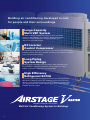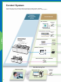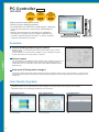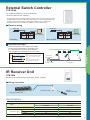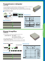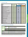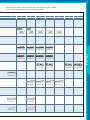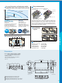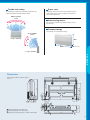
1
TM
Variable Refrigerant Flow System
Multi Air Conditioning System for Buildings
Large Capacity Multi VRF System
DC Inverter Control Compressor
Long Piping System Design
High Efficiency Refrigerant R410A
Building air conditioning developed to care
for people and their surroundings
Large Capacity
Multi VRF System
The ability to connect 3 outdoor units together in series up to a total
capacity of 42HP (120kW) in each 2HP offers greater design freedom,
reducing the number outdoor units and piping installation space
compared the conventional models.
DC Inverter
Control Compressor
The introduction of high efficiency DC inverter compressors and the latest in control
technology provides more precise operation, improving system efficiency, resulting in
energy saving and better economy.
Long Piping
System Design
Maximum piping length 150m. Key design features allows 60m between the
first separation tube and farthest indoor unit. This also allows use in large
buildings and provides a high degree of design flexibility.
High Efficiency
Refrigerant R410A
The V series systems operates using the zero ozone layer depleting potential,
high efficiency refrigerant, R410A. This refrigerant provides increased energy
efficiency, system performance and heat transfer, resulting in a reduction in pipe
sizes compared to previous models. This also leads to cost savings during the
installation phase of a project.
TM
Variable Refrigerant Flow System
Multi Air Conditioning System for Buildings
2
Contents
V series features
1. HIGH RELIABILITY
4
2. IMPROVED COMFORT
6
3. HIGH EFFICIENCY OPERATION
8
4. DESIGN FREEDOM
10
5. EASY INSTALLATION
12
6. SERVICE & MAINTENANCE
14
Control
Control System
16
Comparison with Controllers
18
Wiring System
19
PC Controller
20
Central Remote Controller
22
Group Remote Controller
24
Wired Remote Controller
26
Simple Remote Controller
27
Wireless Remote Controller
28
External Switch Controller
29
IR Receiver Unit
29
BACnet ® Gateway
Network Convertor for LONWORKS
30
®
31
Network Convertor
32
Transmission Adapter
33
Signal Amplifier
33
Service Tool
34
Web Monitoring Tool
36
Outdoor units
Line Up
38
Indoor units
Line Up
40
Compact Cassette
42
Cassette
44
Compact Duct
46
Low Static Pressure Duct / Duct
48
High Static Pressure Duct
50
Floor / Ceiling
52
Ceiling
54
Compact Wall Mounted
56
(Comfort model)
Wall Mounted
58
Ceiling Wall
60
Optional Parts
62
3
HIGH RELIABILITY
High reliability provides a constant comfortable
indoor environment
Compressor rotation control
Improvement of long life by reducing
compressor wear
In addition to control which reduces the number
of times the compressor is started and stopped,
the load at starting is shared and equalized by
rotation control. This rotation improves the
durability and reliability of each compressor.
Compressor starting rotation (Constant speed)
Inverter
4
Constant
speed
Emergency operation
Outdoor unit
Indoor unit
Continuous operation is possible even in the unlikely
event of compressor failure
Continuous operation is possible even if trouble
occurs at an indoor unit
There is no immediate system shutdown if trouble
occurs in any compressor. The other compressors
continue to operate on an emergency basis.
Each indoor unit is controlled individually on the system network.
This allows all indoor units continue to run unaffected even if
trouble should occur at any indoor unit(s) in one system.
Master Unit
Slave Unit
Slave Unit
Failure
Optimum oil control
Stable operation of compressor by optimum oil control
1
High trapping efficiency, large capacity
cyclone type oil separator
2
Oil balance control which maintains
uniform oil levels
3
Optimum EEV control for oil and
refrigerant circulation
Oil separator
Oil equalization pipe
Blue fin heat exchanger mounted
Corrosion-resistance of the heat exchanger even in
coastal areas has been improved by blue fin
treatment of the outdoor unit heat exchanger.
Blue fin heat exchanger
Cobalt Blue protection
Standard chromate protection
Aluminium base material
Hydrophilic coating
Web monitoring tool
Software
UTR-YMSA
VRF System Side
Monitoring Side
Trouble free operation at all times by
web monitoring tool
Outdoor unit
The operational status of the VRF system
within the building can be monitored in real time
over the Internet.
Transmission line
Web
Monitoring Tool
Internet
or
Public Telephone Line
Transmission
Adapter
Indoor unit
*Please contact your distributor for details.
5
IMPROVED COMFORT
Comfort ensured by high precision control technology
Individual air
conditioning system
Pleasant air conditioning meeting individual
room requirements.
6
Room A
Room B
24˚C
18˚C
Room C
Room D
Room E
27˚C
OFF
23˚C
Liquid level balance control
Balancing of the refrigerant in the system is optimized
by liquid level balance control and subcool circuit
between the receiver tanks of each outdoor unit.
Stable refrigerant supply allows long pipe runs and
achieves stable operational system performance
whilst reducing unpleasant refrigerant noise.
Pressure
Stable capacity and reduction of refrigerant noise
by optimum state refrigerant
Subcool
Steady power by sub
cooled liquid-refrigerant
Liquid-level sensor
Subcool H.E.X.
Enthalpy
to
Indoor unit
to Accumulator
Increased refrigerant
capacity by subcool
Large
receiver tank
Room temperature control
Comfort at any time by high precision
High
refrigerant flow control
High precision +
- 0.5˚C ensures comfortable
temperature control of the room. This is
achieved by smooth refrigerant flow,
controlled by inverter and by the indoor unit
electronic expansion valve.
Set temperature
Conventional
New model
26˚C
24˚C
22˚C
Thermal change of the room
Hot
* Simulation in heating operation.
Big variation of room temperature
Waste
Set temp.
Waste
+-0.5˚C
Cold
Quick to reach the
set temperature
Start
Low
Comfortable due to small variation of room temperature
Inverter control
High
Comfort and energy saving achieved by
implementation of inverter control
Smooth capacity
control
Operating capacity
Comfort and energy saving is achieved by the
adoption of linear step control in conjunction with
inverter and constant speed compressor
combination, which allows more precise control of
the necessary refrigerant circulation amount required
according to the system load. This also allows for a
comfortable environment by use of smooth capacity
control.
The capacity control by
the inverter compressor
Inverter
Constant speed
Low
High
Required capacity
Super quiet
Outdoor unit
Indoor unit
Quiet operating sound
outdoor unit achieved
Quiet indoor units suited for
bedrooms and other rooms
which require quietness are
available.
Operating noise has been
reduced further through the
application of a new dual casing
bell mouth and large fan. The
noise level can be reduced by 45dB (A) compared to normal
operation by selecting silent
operation.
Compact Duct
Silent Model
Low Static Pressure Duct
Silent Model
Compact Wall Mounted
Comfort Model
7
HIGH EFFICIENCY OPERATION
High efficiency operation system
Effective use of the heat exchanger
Example
of other outdoor units
This system takes advantage of the features of the
multi type outdoor unit
The heat exchanger is operated at maximum efficiency by
effectively using the heat exchanger of each outdoor unit
reciprocally.
The larger heat exchanger than the capacity of
a compressor is used in each outdoor unit. (V series)
+
+
Conventional method
+
8
+
Large propeller fan
A newly designed fan is adopted for
achieving higher performance and reducing
the noise level.
Sine-wave
DC Inverter Control
By adopting Sine-Wave DC Inverter Control for
smoothing the motor running, energy saving
and high efficiency operation are realized
Adopted
Sine-wave
DC inverter
control
14HP (Master unit)
DC inverter +
Scroll compressor
Equipped
with DC
inverter scroll
compressor
By combining the DC inverter controlled scroll compressor with
the constant speed scroll compressor, an operating system of
energy saving and high efficiency is realized.
High efficiency
High efficiency refrigerant R410A
All key features of the outdoor unit result in a
higher level of COP
Improvement of operation efficiency realized by
adoption of a new refrigerant
Cooling COP
3.2
Refrigerant characteristics (Comparison of R22 / R407C / R410A)
Heating COP
3.7
Refrigerant
Composition element
R22
R407C
R410A
Single
component
Blended
(Zeotrope)
Blended
(Near azeotrope)
* The data refers to a 10HP outdoor unit.
Working Pressure (As compared to R22)
Similar
Higher (1.6 times)
* ”COP” is the coefficient of performance
[= capacity (kW) ÷ input power (kW)].
Capacity (As compared to R22)
Similar
Higher (1.5 times)
Pressure Loss (As compared to R22)
Similar
Lower (0.6 times)
Total Efficiency (As compared to R22)
Similar
Higher (1.05 times)
COP values are base on our own testing method.
9
DESIGN FREEDOM
Design features ensure solutions for all applications
Connectable large capacity
Indoor units up to 150% of the capacity of the outdoor unit can be connected
The Indoor unit connection ratio of this system can be from 50 to 150% of the outdoor unit
capacity, thus achieving a high level of diversification with up to 48 indoor units (30 to 42HP)
connectable on one refrigerant system.
Max.
connectable
capacity
Max.
connectable
indoor units
150%
48
Note : When all indoor units are operating at maximum capacity individual indoor units
operate at a slightly lower capacity.( When connecting more than 100% )
10
Long piping system design
Low outdoor
air temperature
operation
With the V Series, installation up to a maximum piping length of 150m
and a maximum height difference of 50m is possible.
In addition, the piping can be extended up to a maximum of 60m from
the first separation tube.
Expansion of operating ranges
Actual pipe length
World's top class low outdoor air temperature
operating range is achieved. This extends the
potential locations for use to the cold regions of
the world.
*1
C
-15
area
C
-20
area
operation
possible
in cooling
operation
possible
in heating
150 m max.
Height difference
between outdoor
and indoor units
50m max.
For the outdoor
unit stated
below : 40m max.
*1 Note : When outdoor units connect
multiple, operating range is from -5 C
to 43 C in cooling.
50
Cooling
40
43C
30
Height difference
between
indoor units
15m max.
Heating
20
21C
10
0
-10
Pipe length from first
separation tube to
the farthest indoor unit
-15 C
-20C
-20
60m max.
( C)
Compact outdoor unit improves effective use of space
Installation space can be reduced freeing up valuable building space
V series : 28HP system (14 HP
33%
2 units)
Space Save
Space saving which
can be effectively used
39m 2
Conventional model : 28HP equivalent (10 HP
2 units , 8 HP
1 unit )
59m 2
* 12 floors building (28HP capacity is required by each floor )
11
EASY INSTALLATION
Multi air conditioning system for large
buildings with numerous superior
construction work features
Simple communication wiring
Connection method simplifies installation
and prevents errors
Simple piping system
Separation tubes and headers provide connection
flexibility and simplicity reducing installation costs.
By using our wiring connection method, the wiring length is
reduced compared to other wiring systems.
TM
Separation tube
Header
Outdoor unit
Liquid pipe
Indoor unit
Gas pipe
Other wiring method
12
Simple wiring method
Indoor unit
Piping system allows reduction of the number of pipes
Example: 90HP=10HP x 3units x 3
Less
piping
V series
Conventional model
Gas pipe
Liquid pipe
Reduction of
pipe-duct space
Simplified riser piping
Vertical piping of each
refrigerant system need
vertical piping in current
model.
3 risers
9 risers
V series
Conventional model
Pipe shaft
Pipe shaft
Compact outdoor unit can be carried
in a small elevator
1,050
800
650
Outdoor unit goes
into elevator
1,300
1,500
(Unit : mm)
Lifting belt hooks convenient
in crane work
Craning into place
Easy removing pallet
Delivery pallet can be easily removed and installation work can
be performed speedily.
The outdoor unit can be lifted by crane and
set down on the building roof.
Protective boards
Fork
(Hand-forklift)
Delivery pallet
Choice of 4-direction piping connection
Pipe size reduction
Use of R410A refrigerant allows for a pipe size
reduction compared to the conventional system.
This offers improvement in construction work
and a reduction in piping costs.
Slimming down
of piping
o 28.6
In case of gas pipe for 10HP
outdoor unit
Fork(Forklift)
o 22.2
Piping connection
Four-direction pipe
4
Back
4- direction piping allows a variety
of installation configurations.
Easy installation and pipe
direction setting.
1
Front
3
Right
2
Bottom
13
SERVICE & MAINTENANCE
This VRF V Series has numerous special features which
incorporate our newest technology. Service and maintenance are performed accurately and speedily. Confidently
use pleasant air conditioning anytime.
Improves maintenance and
inspection mobility (Service Tool)
Service Tool
UTR-YSTC
Extremely portable and convenient USB type adaptor was used.
Connection anywhere in the VRF network is easy. Data can be
collected from device sensors at a minimum interval of 2 second,
and maintenance and inspection work can performed easily.
Outdoor unit
Transmission line
Intdoor unit
14
USB adaptor
(Field supplied)
Software
Operating display
Outdoor unit
Indoor unit
By indicating the operating status and details of
failures on a PCB in the outdoor unit, better service
and quick and easy maintenance are possible.
The operation status of the indoor unit can be easily checked by
operation indicator. In addition, when an error occurs, the error
contents are displayed and repair work can be performed quickly.
Compact Cassette Type
Compact Wall Mounted Type
Floor / Ceiling Type
Operation
display
Ceiling Wall Type
Note: For duct type indoor units, an IR receiver unit is necessary.
Error display with self-diagnosis function
When an error or abnormality occurred in the system, the indoor unit No. and error code at which the error occurred are displayed at the
display section of the controller. (Except wireless remote controller)
Wired remote controller
Faulty unit number
(Remote controller address)
Error code
Simple remote controller
Faulty unit number
(Remote controller address)
Error code
SU MO TU WE TH FR SA
Drain pan cleaning is easy
Easy replacement
Detachable drain pan simplifies removal of fallen leaves
collected in the drain pan at the bottom of the heat exchanger
Compressor can be moved by pull-out
tray which simplifies inspection and
replacement work. A pull-out plate ensures
easy compressor replacement if necessary.
Heat
exchanger
Fallen leaves
Drain pan
15
Control System
It supports every user's needs by offering a variety of control systems available,
such as individual control, central control and building management system control options
Building
Management
system
Central Control
PC Controller
Transmission
Adaptor
UTR-YTMA
UTR-YOTB
Central Remote Controller
Transmission
Adaptor
CONTROL
UTB-YCA / UTB-GCA
General-purpose
Building Control
Computer
Group Remote Controller
UTR-YTMA
Network
Convertor
Connectable to
various sized BMS / BAS *1
UTB-YDB / UTB-GDB
UTR-YRDA
®
BACnet Gateway
USB
Adaptor*2
or
UTR-YLBA
(Field
supplied)
Network Convertor for LONWORKS®
UTR-YLLA
Web Monitoring Tool
Monitoring Side
VRF System Side
Internet
or
*3
USB Adaptor
UTR-YMSA (Software)
16
Transmission
Adaptor
UTR-YTMA
*1. BMS / BAS: Building Management System / Building Automation System
*2. USB Adaptor is XLON® USB Adaptor of DH Electronics.
*3. USB Adaptor is U10 USB Network interface of Echelon® corporation.
Individual Control
VRF System
Outdoor unit
Wired Remote Controller
UTB-YUB / UTB-GUB / UTB-TUB
Indoor unit
PC Controller
P20
Central Remote Controller
P22
Group Remote Controller
P24
Wired Remote Controller
P26
Simple Remote Controller
P27
Wireless Remote Controller
P28
External Switch Controller
P29
IR Receiver Unit
P29
BACnet® Gateway
P30
Network Convertor for LONWORKS®
P31
Network Convertor
P32
Transmission Adaptor
P33
Signal Amplifier
P33
Service Tool
P34
Web Monitoring Tool
P36
Wireless Remote Controller
CONTROL
UTB-YVB / UTB-GVB
Simple Remote Controller
UTB-YPB / UTB-GPB / UTB-TPB
Signal Amplifier
UTR-YRPC
Simple Remote Controller
UTB-YRA / UTB-GRA / UTB-TRA
Without master control
Card-key
IR Receiver Unit
UTB-YWA
For single split
External switch controller
Network
Convertor
UTR-YRDA
(Field supplied)
UTR-YESA
Service Tool
USB *3
Adaptor
Transmission line
(VRF Network)
Transmission line (RS-232C Cable)
Remote controller line
or
Transmission
Adaptor
UTR-YTMA
Signal line (single system)
LONWORKS® Network
UTR-YSTC (Software)
Ethernet
USB Cable
17
Comparison with Controllers
*2
Item
PC
controller
(software)
Central
remote
controller
Group
remote
controller
Wired
remote
controller
Wireless
remote
controller
Simple
remote
controller
Simple
remote
controller
Model
UTR-YOTB
UTB-YCA
UTB-GCA
UTB-YDB
UTB-GDB
UTB-YUB
UTB-GUB
UTB-TUB
UTB-YVB
UTB-GVB
UTB-YPB
UTB-GPB
UTB-TPB
UTB-YRA
UTB-GRA
UTB-TRA
Max. controllable remote controller groups
400
400
8
1
1
1
1
Max. controllable indoor units
400
400
96
16
16
16
16
Max. controllable groups
400
64
-----
-----
-----
-----
-----
CONTROL
Air conditioning control function
On / Off
-----
Operating mode setting
Fan speed setting
Room temp. setting
Test operation
-----
-----
Up / down air direction flap setting
-----
-----
-----
Right / left air direction flap setting
-----
-----
-----
Auto restart *1
Group setting
-----
-----
-----
-----
-----
RC prohibition
-----
-----
-----
-----
-----
-----
-----
-----
-----
-----
-----
-----
-----
-----
Failure
-----
Defrosting
-----
Display
Current time
-----
Day of week
-----
R.C.prohibition
-----
Cooling / heating priority
-----
Address display
---------
On / Off timer
-----
Timer
Weekly timer
Sleep timer
-----
-----
-----
-----
-----
-----
Program timer
-----
-----
-----
-----
-----
-----
On / Off per day
72
2
2
2
1
-----
-----
On / Off per week
504
14
14
14
-----
-----
-----
-----
-----
-----
Day off
10
10
30
5
-----
-----
Status monitoring system
-----
-----
-----
-----
-----
-----
Electricity charge calculation
-----
-----
-----
-----
-----
-----
Min. unit of timer setting (Minutes)
Control
----10
Error history
*1. Auto restart can be set by DIP switch on PCB inside of indoor unit.
*2. This controller is not available "master control" function.
18
-----
Wiring System
Wiring construction of the control system is made of power source
wiring, transmission wiring and remote controller wiring.
Total wiring length (total length of transmission line) can be
extended up to 2000m (by using signal amplifiers).
Refrigerant system 2
Refrigerant system 1
Connectable
outdoor units
Connectable
indoor units
100
max.
Transmission
line length
400
2000
m
max.
max.
Interlink cable
Transmission
adaptor
UTR-YTMA
PC Controller
. Maximum 400 indoor units can be controlled.
. Air conditioning control
. Operation monitoring
. Status monitoring system
. Electricity charge calculation
Transmission
adaptor UTR-YTMA
Central remote controller
Maximum 16 units can be connected.
One central remote controller can control
up to 64 groups / 400 indoor units.
Network convertor
UTR-YRDA
Group remote controller
Maximum 8 remote controller groups can be controlled
Building Management System
BACnet ®
BACnet ® Gateway
USB
adaptor
Remote controller line
Maximum 16 units can be controlled
BACnet ® Operator
Workstation (B-OWS)
Network
convertor
UTR-YLLA
System without remote controller
Together with central remote controller, it is
possible to build non remote controller system.
LONWORKS®
IR receiver unit
Duct type indoor unit
can be controlled with
wireless remote controller.
LONWORKS ®
Network
Card key
Signal
Amplifier
UTR-YRPC
External switch controller
2 remote controllers
Indoor unit can be controlled
from both remote controllers.
Transmission line
line is non-polar 2-conductor.
Indoor units can be controlled by combining
with Card-key switch such as hotel room.
Network convertor
UTR-YRDA
Transmission adaptor
UTR-YTMA
Web monitoring tool
Trouble free operation at all times
by remote monitoring system.
CONTROL
BACnet ®
Network convertor
UTR-YRDA
Web monitoring tool
Service tool
(VRF system side)
Internet
or
Public Telephone Line
Big multi system
Single system
Service tool
Extensive monitoring and analysis functions
for installation and maintenance.
Monitoring side
USB adaptor
(Field supplied)
Outdoor unit
Central remote
controller
Simple remote
controller
Transmission line
(non-polar 2-conductor)
Remote controller
line
Monitoring side
Indoor unit
(Cassette)
Group remote
controller
Wireless remote
controller
Indoor unit
(Duct)
Wired remote
controller
External switch
controller
Monitoring side
Transmission line
(RS-232C Cable)
LONWORKS®
Network
Ethernet
Combination of individual remote controller
Wired, wireless and simple remote controllers can be used jointly.
PC controller
Simple remote
controller
IR receiver unit
Signal line
(single system)
19
PC Controller
UTR-YOTB
Software
Max.
controllable
indoor units
Max.
controllable
groups
400
400
Max.
controllable
remote controller
groups
400
High performance and optimum control
system for various building applications
Up to 400 indoor units / 400 remote controller groups / 400 groups
can be connected into one system for large scale buildings or
hotels.
Provides powerful functions for building air conditioning
management, including electricity charge calculation and
numerous data management functions, as well as standard
equipment monitoring and control.
Functions
Central building monitoring and control
Detailed settings can be programmed for each whole building / group / remote
controller group.
The PC controller and central remote controller can be used together to permit
system control from two or more locations, if required.
Central control
CONTROL
Any of 6 functions of the individual remote controller can be locked to permit access
from the PC controller: all functions, timer mode, operating mode, temperature
setting, filter reset, on / off. Or the system can be set to allow control from the PC
Controller only.
Operation Control
Auto mode (Priority-mode changer)
Auto mode function automatically switches between cooling and heating modes based on the temperatures set and the room
temperature detected by the master indoor unit. Other operating indoor units can be operated in the same operating mode as
master unit.
User-friendly Operation
Runs under Windows® 2000 and Windows® XP Professional / Home so is as easy to use as a standard PC.
Operational status can be color-coded for instant recognition: On / green, Off / red, test / orange, error / flashing.
Operational status can be displayed according to user,s preference.
20
Rotating 3-D Display
Floor Layout Display
List Table Display
When monitoring and controlling the operations
of a whole building.
When monitoring and controlling the operations
of each floor or group.
When monitoring and controlling each unit in
detail.
Electricity charge calculation
Error display
Total electricity charge, billed for multiple indoor units connected to the
charge meter for air conditioning, is apportioned according to the
accumulated operation time and indoor unit capacity.
Allows accounting for special rates (e.g., for night or weekend use).
Calculations can be printed as final bills.
Audible alarms are accompanied by explanatory
text. Up to 100 alarms can be recorded for each
piece of equipment, this is particularly useful during
maintenance.
Electric bill
Bill
Block(Tenant) A
M
Meter
ELECTRICITY
COMPANY
Input data
Apportioned
charges
Error Warning
Block(Tenant) B
PC controller
Block(Tenant) C
BUILDING
Operating record
The operating status of indoor units and
accumulated operating time of outdoor units can be
logged and a daily or monthly report produced.
Note: This electrical power apportioning calculation is not official.
When issued to the user as a bill, it must be explained to the user in advance.
Schedule control
Annual schedules can be set for
each remote controller group.
Start / stop, operating mode,
remote controller prohibition, and
temperature settings can be
recorded up to 72 times per day at
10 minute intervals for up to 6
configurations for each remote
controller group.
Schedule Control
Settings can be made for periods
straddling midnight.
Allows programming of special settings for holidays, including public
holidays, for a complete year.
Standard 6 functions are available by schedule control.
CONTROL
Operation Record
Pattern setting
Recognizes patterns of use, including ON/OFF,
operating mode, and set temperature. An arbitrary
pattern operation can be done by the touch of one
button.
Easy Installation
Outdoor units
Interlink
cable
Simple connection by Transmission
Adaptor and Interlink cable (Interlink
cable field supplied).
Easy software installation using just the
CD provided.
(Field supplied)
Indoor units
Transmission
Adaptor
(Field supplied)
Requirements of PC for this software
Operating System
Personal
Computer
CPU
HDD
Memory
Interface
Accelerator
Software
Hardware
AT compatible machine that runs Microsoft® Windows®
Microsoft® Windows® 2000 Professional (English version / Service pack3 or later)
Microsoft® Windows® XP Professional / Home (English version / Service pack1 or later)
Intel® Pentium® / Celeron®, AMD Athlon / Duron 1GHz or higher
4 GB or more
256 MB or more
Serial port and USB port
Requires that the internal graphics accelerator be compatible with Microsoft® DirectX® 7.0 or later
Adobe® Acrobat® Reader 4.0 or later
Interlink cable (D-sub 9 pin female connector) [Field supplied]
TM
TM
<PACKING LIST>
Packing List
CD-ROM / Transmission Adaptor (UTR-YTMA) / Software Protection Key
21
Central Remote Controller
UTB-YCA / UTB-GCA
Max.
controllable
indoor units
Max.
controllable
remote controller
groups
Max.
controllable
groups
400
400
64
Functionality in a compact housing with
built-in weekly timer
Up to 400 indoor units / 400 remote controller groups / 64 groups can be
controlled by one system.
Up to 16 central remote controllers can be connected into one system
allowing operation and monitoring to be achieved from the central control
room, at each floor, by each tenant, or in the plant room.
Functions
Control up to 400 indoor units
Controllable method
CONTROL
The central remote controller performs system
control after you select All Groups, User Defined
Groups, or Individual Remote Controller Groups.
Accurate control of functions such as Start / Stop,
Operating Mode, Temperature, and Air Velocity
ensures occupancy comfort.
All
Group
Group
Group
All Groups
User Defined Groups
Individual
Individual
Individual
Individual Remote
Controller Groups
Group
Group
Central control
Any of 6 functions of the individual remote controller
can be locked from the Central Remote Controller: all
functions, timer mode, operating mode, temperature
setting, filter reset, on / off.
All functions can be controlled via the Central
Remote Controller only.
Individual
Individual
Individual
Easy Operation
Control functions are divided into three clusters: Timer Control, Central Control
and Operational Control, which are clearly displayed.
A large liquid crystal display clearly indicates which indoor unit is currently
operating.
TIMER
CONTROL
AREA
All Control Mode
22
Group Control Mode
Individual Control Mode
CENTRAL
CONTROL
AREA
OPERATION
CONTROL
AREA
Example: Office
Built-in weekly timer
Capable of controlling up to 400 indoor units, the timer function enables
detailed scheduling for each remote controller group.
A simple approach to system configuration reduces wiring costs.
1.Allows two daily ON / OFF times for each day of the week.
2.Allows time settings in 10 minutes increments.
3.Time operations for a certain day can be temporarily
cancelled by pressing the "DAY OFF" button in advance.
4.Timer settings can be carried over to the following day.
5.Daily time settings allow Copy and Paste functionality.
Weekly schedule
Example : Office
On
Off
Sun
Mon
Tue
Wed
Thu
Fri
Sat
Operation : Monday~Friday 8:00~12:00 and 13:00~18:00
Memory functions
Operating
conditions of
all indoor units
can be
memorized
Central remote controller maintains original settings for all indoor
units. This data can easily be transmitted to the system even after
operating conditions have been changed.
Outdoor units
Indoor units
Transmission line
CONTROL
Error display
Error codes can be displayed for all indoor units and outdoor units.
The last 2 error codes can be displayed, for easy inspection,
service and maintenance.
Simple and Convenient Installation
The controller can be installed
on any flat surface.
The control panel and
transmission adaptor can be
installed separately.
For flexibility in installation, the
main unit can be built into the
wall or exposed.
Transmission line
Connecting
cable
Setting Example (1)
Transmission
Adaptor
Power Supply
220-240V
Wall
Control Panel
Behind
ceiling
Possible to extend
up to 5m. (Max)
(optional service
parts)
Control
Panel
Transmission
Adaptor
Setting Example (2)
Control
Panel
Transmission
Adaptor
Specifications
UTB-YCA / UTB-GCA
Model
Power Supply
Power Consumption (W)
Fuse Capacity (A)
Dimensions (H x W x D)(mm)
Weight (g)
Control Panel
Transmission Adaptor
DC 12V
220-240V 50-60Hz Single phase
4.8
3
143 x 296 x 22
550
107 x 288 x 100
1,300
<PACKING LIST>
Packing List
Control Panel / Transmission Adaptor / Connecting Cable
23
Group Remote Controller
UTB-YDB / UTB-GDB
Max.
Max.
connectable
controllable
remote controller Group R.C.
in a VRF system
groups
64
8
Group control of indoor units with simple operation
Up to 8 remote controller groups can be controlled by a single controller.
Up to 64 Group Remote Controllers can be connected in a single VRF system.
Network Convertor (UTR-YRDA) is required to connect Group Remote Controllers to a
VRF system.
Functions
High performance and compact size
ON / OFF, operating mode, set temperature and
air flow can be controlled / monitored centrally or
individually.
Central
control
ON/OFF
control
Weekly
timer
Control up to 8 remote controller groups
CONTROL
A single Group Remote Controller controls and monitors up to 8 remote controller groups.
Up to 64 Group Remote Controllers can be connected in a single VRF system.
Up to 4 Group Remote Controllers can be controlled by a single Network Convertor (UTR-YRDA).
Office & hotel building (Small class)
Group remote controller 2 for hotel floor
Meeting room
Guest room
Outdoor units
Restaurant
Lobby
Simple Remote
Controller
Group Remote Controller 1 for office floor
Wired
Remote
Controller
Lobby
Office room
Network
Convertor
Wireless
Remote
Controller
1
2
Group Remote
Controller
Wired Remote Controller
Office room
Meeting room
Wired Remote
Controller
Restaurant
Up to 8 remote controller groups
Built-in weekly timers
Time
Air conditioning ON/OFF
setting corresponding to air
conditioning specification
needs is possible.
24
Temperature switching
Temperature switching
(Peak cut)
(Anti-freeze)
Time
Switching between the
cooling mode and heating
mode can be set by time.
Ope.
Time
Since peak power cut is
performed in a planned
way, setting which changes
the room temperature
linked with time is possible.
Stop setting
Ope.
Cooling / Heating switching
Ope.
Ope.
ON / OFF switching
Ope.
The weekly timer is provided as a standard function.
1. The timer can be set up for up to 4 times per day. (On / Off, operating mode, set temperature)
2. Allows separate settings for each day of the week.
Time
Low temperature heating
operation can be set to
prevent freezing in cold
regions at night, etc.
Time
Indoor unit start/stop
matched to the air
conditioning operation end
time is possible.
Useful functions
1
Timer setting at all the
connected indoor units is
possible by centralized timer on
the front panel.
Indoor Unit
Operation Indicators
This shows the operating status and timer
operation status for each of the indoor units.
With cover closed
: On
: Timer operation
: Off
: Selection
Operation Lamp
2
This is on if any of the indoor units is
operating.This flashes if any of the indoor
units has malfunction(s).
All the connected indoor units
can be turned on / off
simultaneously by centralized
ON/OFF button on the front of
the cover.
ALL OFF Button
Press the ALL OFF button to turn off all of
the indoor units.
ALL ON Button
3
The indoor unit can be quickly
turned on and off by ON / OFF
button of each indoor unit on the
front of the door.
Press the ALL ON button to turn on all of the
indoor units.
ALL TIMER Button
Press the ALL TIMER button to turn the timer
operation on or off for all indoor units.
Start / Stop Button
Indoor Unit Name Labels
Timer and Clock
Display and setting
CONTROL
Press the ON / OFF button to turn the
corresponding indoor unit on or off.
Write the names of the indoor units on the
included labels and attach them.
Displaying the Status
and Controlling
indoor units
With cover open
Transmission Display
Setting Display
Operation Lock Display
Day Display
ON / OFF Display
Timer and
Clock Display
Fan Speed Display
Set Temperature Display
Timer Mode Display
Operation Mode Display
Timer Mode
(DELETE) Button
Start / Stop Button
Select Button
DAY Button
Set Time Button
PROGRAM (CLOCK
ADJUST) Button
Fan Control Button
Master Control Button
ENTER Button
Set Temperature Button
Specifications
Group Remote Controller
Model
UTB-YDB / UTB-GDB
Power Supply
Dimensions (mm)
DC 12V
Height
120
Width
Depth
120
17
Weight (g)
DC12V power supply is supplied by a network converter.
200
25
Wired Remote Controller
UTB-YUB / UTB-GUB / UTB-TUB
Max.
controllable
indoor units
The room temperature can be controlled by detecting
the temperature accurately from the built-in sensor
16
Simple operation with Built-in Weekly / Daily Timer.
A single controller controls up to 16 indoor units.
Up to 2 wired remote controllers can be connected to a single indoor unit.
Functions
Powerful features and compact size
Built-in timers
This Wired Remote Controller incorporates three primary
functions into a single unit.
Wired
Remote
Control
Weekly
timer
Weekly timer :
Setback timer :
Two ON / OFF times can be set
for each day of the week.
Easy-to-understand time bar display
Setback
timer
Allows the user to set temperatures
for two time spans over the course
of each day of the week.
Setup screen example
(Set from Sunday to Saturday:
12:00 to 15:00, 28 C.)
Setup screen example
(Set to Wednesday: 8:00 to 20:00.)
Screen
after setup
Accurate and comfortable
CONTROL
Indoor temperature can be detected accurately by the
inclusion of a thermo sensor in the body of the wired
controller. Our system can correspond to various scenes.
This new wired
Sensor part
remote controller and
the optional remote
Thermo sensor
sensor allows
display
flexibility in sensor
location, suitable for
Control part for
all requirements.
changing the
thermo sensor
Example of changing sensor
Remote Sensor
in the bedroom
(in effect during
the night)
0
3
6
9
12
24 C
15
18
21 Time
0
3
6
9
28 C
15 18
12
21 Time
At "Weekly timer" + "Set back timer" setup
24 C
28 C
28 C
24 C
24 C
0
3
6
9
12
15
18
21
Time
Diagnosis check function
Two methods are available for determining the
cause of failure in the event of a malfunction
occurs:
Malfunction diagnosis function
Error history (Last 16 error codes can be
accessed)
Simple installation
Indoor unit
Can be mounted on the European Mounting Box
(Installation dimension: 60mm) or the JIS Built-in
Box (Installation dimension: 83.5mm).
Day
Wired Remote
Controller
Night
JIS built-in box
Remote
Sensor
The detecting point
can be easily changed
Remote controller
in the living room
(in effect during the day)
European
mounting box
Displayed temperature is set temperature.
Specifications
Wired Remote Controller
Model
UTB-YUB / UTB-GUB / UTB-TUB
Power Supply
Dimensions (mm)
DC 12V
Height
120
Width
120
17
160
Depth
Weight (g)
26
DC12V power supply is supplied by the indoor unit.
Simple Remote Controller
UTB-YPB / UTB-GPB / UTB-TPB
UTB-YRA / UTB-GRA / UTB-TRA
Compact remote controller provides access to basic functions
Up to 16 indoor units can be controlled with one remote controller.
Suitable for hotels or offices which have many visitors coming in and going
out and do not require detailed functions.
Max.
controllable
indoor units
16
UTB-YPB / UTB-GPB /
UTB-TPB
UTB-YRA / UTB-GRA /
UTB-TRA
Without master control
User-friendly operation
Background light
Provides access to basic operations, such as Start / Stop, Fan
Control, master control Switching, and Temperature Setting.
A large Start / Stop button is provided in the centre of the remote
controller unit for easy operation.
Can be incorporated with the standard remote controller.
Following an error display, Diagnostics can be carried out on the
controller.
Backlight enables easy operation
in a darkened room.
Backlight activates during all
button operations, and lasts 10
seconds in operating mode and 5
seconds in stop mode after a
button is pressed.
Simple installation
Functions
Can be mounted on the European Mounting Box (Installation
dimension: 60mm) or the JIS Built-in Box (Installation dimension:
83.5mm).
CONTROL
Functions
Model
European
switch box
UTB-YPB
UTB-GPB
UTB-TPB
Operation
UTB-YRA
UTB-GRA
UTB-TRA
Start / Stop
Fan control
*1
Master control
JIS built-in box
Temp. setting
*1: This controller is limited a part of function.
It is recommend to use together with other type controller.
Specifications
Simple Remote Controller
Model
UTB-YPB / UTB-GPB / UTB-TPB
Power Supply
Dimensions (mm)
UTB-YRA / UTB-GRA / UTB-TRA
DC 12V
Height
120
Width
Depth
75
14
Weight (g)
DC12V power supply is supplied by the indoor unit.
90 (100 : UTB-TPB)
90 (100 : UTB-TRA)
27
Wireless Remote Controller
UTB-YVB / UTB-GVB
Simple and sophisticated operations
with a choice of 4 daily timers
A single controller controls up to 16 indoor
units.
Max.
controllable
indoor units
Selectable
4
16
daily
timers
UTB-YVB / UTB-GVB
Functions
Built-in daily timer
CONTROL
Select from 4 different timer programs : On / Off / Program / Sleep
Program timer : The program timer operates the ON and OFF timer once within a 24 hour period.
Sleep timer : The sleep timer function automatically corrects the set temperature according to the time setting to prevent
excessive cooling or heating during sleep hours.
Cooling operation/dry operation
Heating operation
When the sleep timer is set, the set temperature
automatically rises 1 C every hour. The set
temperature can rise up to a maximum of 2 C.
When the sleep timer is set, the set temperature
automatically drops 1 C every 30 minutes. The set
temperature can drop to a maximum of 4 C.
1C
T imer setting
60min.
2C
3C
4C
30min.
60min.
2C
90min.
1C
Timer setting
Easy installation and operation
Code selector switch prevents indoor unit
mix-up. (Up to 4 codes can be set.)
System addressing
Wide and precise
transmitting range.
During installation work, system addressing can
be performed using the wireless remote
controller, thus eliminating manual switch
setting.
Transmission line
Outdoor unit
Indoor unit
Wireless
remote controller
Specifications
Wireless Remote Controller
Model
UTB-YVB / UTB-GVB
1.5V (R03 / LR03 / AAA) x 2
Battery
Dimensions (mm)
Weight (g)
28
Height
158
Width
Depth
56
20
70
External Switch Controller
UTR-YESA
Air conditioner switching can be controlled by
connecting other sensor switches
In combination with a field supply Card-Key Switch or other sensor, the external switch
controller allows control of the ON / OFF, Temperature, fan speed and operating mode
functions. This makes this product suitable for installations such as hotel rooms.
Card-key or other sensor switches are available as a field supplied parts.
Electrical wiring
Indoor Unit
Indoor Unit
1
2
3
E
COM SW1 SW2
Remote
Controller
Line
Card-key
Card-key
(Field supplied)
1
2
3
Remote
Controller
Line
External
input
EXTERNAL SWITCH
CONTROLLER
E
COM SW1 SW2
Sensor SW
(Field supplied)
External
input
EXTERNAL SWITCH
CONTROLLER
Sensor SW
Installation example
Auto mode operation, which switches the cooling
and the heating automatically, is enabled by using
the sensor switch and external switch controller.
Note: All indoor units will operate in the same mode.
SU MO TU WE TH FR SA
7
T1
T2
Sensor SW
(Field supplied)
Note 2.
The remote controller's operation is
prior to the auto mode operation.
Heating
Time
CONTROL
Room temp.
3 6 9 12 15 18 21
Note 1.
Please choose a thermosensor switch
which can be set up for T1 and T2.
Cooling
To individual dry contact
T1 = ON, T2 = OFF
External switch controller
(UTR-YESA)
IR Receiver Unit
UTB-YWA
Necessary to control duct type by wireless remote controller
Wiring connection
IR Receiver Unit
Duct Type Indoor Unit
Wireless
Remote Controller
Specifications
Model
Power Supply
Height
Dimensions (mm)
Width
Depth
Weight (g)
DC12V power supply is supplied by the indoor unit.
External Switch Controller
IR Receiver Unit
UTR-YESA
UTB-YWA
DC 12V
DC 12V
120
75
30
122
60
26.5
90
150
29
BACnet ® Gateway
UTR-YLBA
Software
Max.
controllable
Max.
controllable
400
1600
outdoor units
indoor units
4
VRF system
Max.
controllable
The VRF system can be incorporated into a Building Management System.
Enables central control of up to 1,600 indoor units through BACnet®, a global standard
for open networks.
ANSI / ASHRAE Standards® 135-2001 BACnet® Application Specific
Controller (B-ASC) BACnet® / IP over Ethernet.
Connects up to 4 VRF systems (1,600 indoor units / 400 outdoor units) per gateway.
Ideal for applications in high rise buildings and hotels, etc.
CD-ROM
(Software)
Software
Protection Key
Installation example
VRF system 1
*1
BACnet ®
USB Adaptor
Indoor unit
Outdoor
unit
BACnet ® Operator
Workstation (B-OWS)
VRF system 2
USB Adaptor
Outdoor
unit
CONTROL
Indoor unit
Lighting facilities
BACnet ® Gateway
(UTR-YLBA)
USB Adaptor
Security system
Automatic fire alarm interface
CD-ROM
Software
(Software) Protection Key
Ventilation system
(Max. 4 systems)
= BACnet® gateway for each system.
USB Adaptor
= USB cable
*1: An XLON ® USB adaptor is field supplied.
(XLON ® is a registered trademark of DH electronics company Gmbh.)
= Transmission line
(VRF Network)
= Ethernet
Requirements of PC for this software
AT compatible machine that runs Microsoft® Windows®
Personal
Computer
Operating
System
Microsoft® Windows® 2000 Professional (English version / Service pack3 or later)
CPU
Intel® Pentium® III 400MHz or higher
Memory
256 MB or more
Display
1024 x 768 dots or more
Interface
USB 1.1
Microsoft® Windows® XP Professional (English version / Service pack1 or later)
LAN (10BASE-T / 100BASE-TX)
*The power supply of 100mA / 5VDC is necessary for one USB adaptor.
Personal Computer (Field supplied)
Required Hardware
USB Adaptor (DH electronics XLON® USB USB4-WM-FTT) (Field supplied)
*1 adaptor is necessary for 1 VRF system.
Required Software
Adobe® Acrobat® reader 4.0 or later
<PACKING LIST>
Packing List
30
CD-ROM / Software Protection Key
Network Convertor for LONWORKS®
UTR-YLLA
Max.
connectable
128
indoor
units
For connection between VRF system and a LONWORKS® open network for management
of small to medium-sized BMS and VRF systems.
The UTR-YLLA permits central monitoring and control of a VRF system from a BMS
through a LONWORKS® interface.
Up to 128 Indoor units can be connected to a single Network Convertor.
Network convertor
(UTR-YLLA)
Installation example
VRF System Network
Maximum 128 units
Lighting facilities
CONTROL
General-purpose
building control computer
(LONWORKS® device)
VRF system 1
Security system
VRF System Network
Automatic fire
alarm interface
Maximum 128 units
Ventilation system
LONWORKS®
Network
VRF system 2
Specifications
Dimensions
Main specification
50-60Hz
Power Supply
220-240V
4.5
Power Consumption (W)
Dimensions (H X W X D) (mm)
BMS SIDE
Transceiver
Transmission way form
Termined resistor
78kbps
FTT-10A
Free topology
None (It attaches at the
terminal of a network.)
211
Transmission specification
95 (Hole pitch)
1,500
95 (Hole pitch)
Weight (g)
Transmission speed
2- 5
For M4x20L screws
67 X 288 X 211
4- 5
For M4x20L
screws
241.6
272 (Hole pitch)
288
67
31
Network Convertor
UTR-YRDA
This network convertor is to be used for connecting single split system or
group remote controller (UTB-YDB / UTB-GDB) with the VRF system.
Please select the function by switching the dip switch during the installation.
Installation example
Split type systems can be controlled from a central remote controller or PC controller through
connection to the VRF's network convertor.
Used for
Standard remote controller and central remote controller provide On / Off control, master control, connecting
single split
temperature and fan control, etc.
system
A single network convertor can be used to connect and control up to 16 single units.
Network convertor
(UTR-YRDA)
Group of Single Split
VRF system
CONTROL
Single Split
Please consult your distributor for connectable split type air conditioner.
Up to 100 network convertors may be connected in a single VRF system.
A single network convertor is considered as a single refrigerant system,
irrespective of the number of connected single models.
Big Multi
4 group remort controllers can be connected to a single Network convertor (UTR-YRDA).
Max.
connectable
Network Convertor
Used for
connecting
Group Remote
Controller
16
units
Group Remote Controller
UTB-YDB / UTB-GDB
VRF system
Network Convertor
(UTR-YRDA)
Specifications
* 2 refrigerant circuits can be covered by a single network convertor (UTR-YRDA) .
Up to a total of 16 network convertors (UTR-YRDA) and central remote
controller adapters can be connected in a single VRF system.
Dimensions
Main specification
Dimensions (H X W X D) (mm)
8.5
2- 5
For M4x20L screws
67 X 288 X 211
1,500
95 (Hole pitch)
Weight (g)
220-240V
211
Power Consumption (W)
50-60Hz
95 (Hole pitch)
Power Supply
4- 5
For M4x20L
screws
32
241.6
272 (Hole pitch)
288
67
Transmission Adaptor
UTR-YTMA
For air conditioning of the medium and large size buildings, the control software can control and
monitor air conditioners together with the ones in the other buildings.
This device enables control by other equipment via an Interlink cable or connection cable.
Up to 400 Indoor units / 100 Outdoor units can be connected to one Transmission Adaptor.
Installation example
Web
Monitoring
Tool
VRF system
Interlink
Cable
Dimensions
Transmission line
(non-polar 2-conductor)
PC Controller
Central Remote Controller
Service Tool
Specifications
243
220-240V
90
2.9
Power Consumption (W)
106.6
50-60Hz
Power Supply
3A
Fuse Capacity
Dimensions (H X W X D) (mm)
100 X 288 X 110
Weight (g)
100
277
CONTROL
1,300
Signal Amplifier
UTR-YRPC
This unit allows the connection of the following number of units:
(1) Transmission Line : Max. 2,000m
(2) Connectable Units : Max. Indoor Unit : 400 units
Max. Outdoor Unit : 100 units
Max. Central Remote Controller : 16 units
Up to 8 signal amplifiers can be installed in a single VRF system.
A signal amplifier is required,
(1) When the total wiring length of the transmission line exceeds 500m.
(2) When the total number of units on the transmission line exceeds 64.
Installation example
B
between A and B : 100m
between B and C : 200m
between B and D : 500m
Dimensions
C
A
Specifications
Power Supply
Power Consumption (W)
Dimensions (H X W X D) (mm)
Weight (g)
50-60Hz
220-240V
4.5
67 X 288 X 211
1,500
211
D
95 (Hole pitch)
Signal Amplifier
95 (Hole pitch)
2- 5
For M4x20L screws
4- 5
For M4x20L
screws
241.6
272 (Hole pitch)
288
67
33
Service Tool
Monitored
and controlled
Software
100
UTR-YSTC
outdoor units
Monitored
and controlled
400
indoor units
Extensive monitoring and analysis functions for installation
and maintenance
Operation status can be checked and analyzed to detect even the smallest abnormalities.
Storage of data on system operation status on a PC allows access even from off site.
Up to 400 indoor units (a single VRF system) can be controlled and monitored for large scale
buildings or hotels.
This software can be connected to any point of transmission line with USB adaptor (field
supplied)
Wiring connection
Refrigerant piping
CONTROL
Indoor unit
USB adaptor
(Field supplied)
or
Transmission
adaptor
(UTR-YTMA)
Transmission line
Indoor unit
(Field supplied)
Easy to
carry out with
USB adaptor
*USB Adaptor is U10 USB Network interface of Echelon® corporation.
Functions
34
Equipment Detail (Diagram)
Equipment Detail (List)
Displays the detail information for sensor values,
electrical components etc. for the specified units in
schematic. The information here can be used along with
the detail information in list form, to check the operation
status of units and make detail analysis on the cause, in
case an error occurs.
Displays the detail information for sensor values,
electrical components etc. of units in a specified
refrigerant system in list form.
The information here can be used along with the detail
information in diagram form, to check the operation status of
units and make detail analysis on the cause, in case an
error occurs.
Error History
System List
Displays the error information for each unit. The error
information can sequentially be displayed up to 50
items as they occur starting with the latest error.
Displays the overall operation status of all or
specified units in the system in a list form.
Commissioning Tool
CONTROL
Test run commands can be executed with this tool.
During test running, the outdoor unit / indoor unit sensor
data can be saved (commissioning log data).
After the end of test running, this data can be exported
in CSV file format.
Remote File Download
Operation and error history data can be downloaded.
Only the required data may be downloaded specifying the
refrigerant system, unit and time range.
Requirements of PC for this software
Personal
Computer
Operating
System
CPU
HDD
Memory
Interface
Software
Hardware
AT compatible machine that runs Microsoft ® Windows ®
Microsoft ® Windows ® 2000 Professional
(English version / Service pack3 or later)
Microsoft ® Windows ® XP Professional
(English version / Service pack1 or later )
TM
TM
Intel ® Pentium ® / Celeron ® , AMD Athlon / Duron 1GHz or higher
2.1 GB or more
256 MB or more
Serial port and USB port
Internet Explorer 6.0 or later / Adobe ® Acrobat ® Reader 4.0 or later
Interlink cable D-sub 9 Pin [Field supplied]
USB Adaptor is U10 USB Network
or
Transmission Adaptor (UTR-YTMA)
interface of Echelon ® corporation.
<PACKING LIST>
Packing List
CD-ROM / Software Protection Key
The transmission adaptor or the USB adaptor of optional parts is necessary to connect this software with the VRF system.
35
Web Monitoring Tool
4
Software
1600
Indoor unit
VRF system
can be
supported
UTR-YMSA
can be
monitored
Product features
Troubleshooting is performed by monitoring each air conditioning unit remotely during periodical system checks.
Error notification can be automatically transmitted to several locations using the internet*.
Requires either a dedicated internet connection* or public telephone line.
Determination of an error occurrence can be made through error warnings and equipment status information obtained from a
remote location.
The monitoring data in a remote side can be optionally downloaded. And, this data can be displayed in off-line mode of the
service tool.
Monitoring side computer is not required to install special software, required only general web browser.
*Unchanging global IP address is required.
Web Monitoring System
VRF System Side
Monitoring Side
Outdoor unit
Transmission line
CONTROL
Web
Monitoring Tool
Internet
or
Public Telephone Line
Transmission
Adapter
Indoor unit
System components
Support 4 VRF system
Monitoring Side
PC Transmission adaptors (max. 4 adaptors per PC)
permit control and monitoring of up to 1,600 units.
Suitable for large-scale buildings or hotels.
VRF System Side
Personal Computer
(Field Supplied)
Software
(UTR-YMSA)
Personal
Computer
(Field Supplied)
Software
Protection
Key
Internet
or
Public Telephone Line
Interlink cable
(Field Supplied)
Transmission
Adaptor
(UTR-YTMA)
or
USB adaptor
(Field Supplied)
VRF System
36
VRF System1
Indoor unit :
VRF System2
Indoor unit :
VRF System3
Indoor unit :
VRF System4
Indoor unit :
Max.400
Max.400
Max.400
Max.400
Comparison table
Web Monitoring Tool
Item
UTR-YSTC
1
Interchangeability of equipment
2
Indication of equipment list
3
Operation control
4
Indication of unit circuit diagram
5
Commissioning tool
6
Monitoring of equipment information
7
Monitoring of operating condition
8
Monitoring of sensor data
9
Indication of trend graph
10
Storage and CSV output of operating
history (sensor data)
11
Printing of trend graph
12
Monitoring and screen display
of abnormalities
13
E-mail automatic transmission
of abnormalities
14
Setting for user level
UTR-YMSA
Monitoring Side
VRF System Side
CONTROL
No.
Service Tool
*1
*1 It is available only during a connection to the Internet.
Requirements of PC for this software
Personal
Computer
Operating
System
CPU
HDD
Memory
Interface
Software
Hardware
AT compatible machine that runs Microsoft ® Windows ®
Microsoft ® Windows ® 2000 Professional
(English version / Service pack3 or later)
Microsoft ® Windows ® XP Professional
(English version / Service pack1 or later )
TM
TM
Intel ® Pentium ® / Celeron ® , AMD Athlon / Duron 1GHz or higher
2.1 GB or more
512 MB or more
Serial port (Max. 4) *1and USB port
Internet Explorer 6.0 or later / Adobe ® Acrobat ® Reader 4.0 or later *2
Interlink cable D-sub 9 Pin [Field supplied]
USB Adaptor is U10 USB Network
or
Transmission Adaptor (UTR-YTMA)
interface of Echelon ® corporation.
<PACKING LIST>
Packing List
CD-ROM / Software Protection Key
1 port required for each VRF system connected.
If Internet Explorer is installed on the remote side PC, remote supervision of VRF system status is available.
The transmission adaptor or the USB adaptor of optional parts is necessary to connect this software with the VRF system.
*1
*2
37
Outdoor Units
Model name
Outdoor Unit Line up
By combining 6 types (Master Unit and Slave Unit
8/10/14 HP) of 1 to 3 Outdoor Units, ranging from 8
HP (22.4 kW) to 42 HP (120 kW).
Master units
Capacity
Slave units
22.4kW (8HP)
AJ*A72LATF
AJ*A72UATF
28.0kW (10HP)
AJ*A90LATF
AJ*A90UATF
40.0kW (14HP)
AJ*126LATF
AJ*126UATF
AJ* : AJY (FUJITSU), AJG (GENERAL)
OUTDOOR UNIT
Capacity range
HP
Capacity
(kW)
Combination of outdoor units
Maximum
Ratio of
Total capacity
Connectable
outdoor unit
Indoor unit of Indoor unit (kW)
capacity
15
HP
Capacity
11.2-33.6
8
22.4
AJ*A72LATF
14.0-42.0
10
28.0
AJ*A90LATF
20.0-60.0
14
40.0
AJ*126LATF
22.4-67.2
16
44.8
AJ*A72LATF AJ*A72UATF
Unit
Master
(kW)
Slave1
Slave2
8
22.4
10
28.0
14
40.0
16
44.8
18
50.4
25.2-75.6
18
50.4
AJ*A90LATF AJ*A72UATF
20
56.0
28.0-84.0
20
56.0
AJ*A90LATF AJ*A90UATF
22
62.4
31.2-93.6
22
62.4
AJ*126LATF
AJ*A72UATF
24
68.0
24
68.0
AJ*126LATF
AJ*A90UATF
26
72.8
36.4-109
28
80.0
AJ*126LATF
AJ*126UATF
28
80.0
40.0-120
26
72.8
AJ*A90LATF AJ*A72UATF AJ*A72UATF
30
84.0
42.0-126
30
84.0
AJ*A90LATF AJ*A90UATF AJ*A90UATF
32
90.4
45.2-135
32
90.4
AJ*126LATF
AJ*A90UATF AJ*A72UATF
34
96.0
48.0-144
34
96.0
AJ*126LATF
AJ*A90UATF AJ*A90UATF
36
102
51.0-153
36
102
AJ*126LATF
AJ*126UATF
AJ*A72UATF
38
108
54.0-162
38
108
AJ*126LATF
AJ*126UATF
AJ*A90UATF
42
120
60.0-180
42
120
AJ*126LATF
AJ*126UATF
AJ*126UATF
16
30
32
34.0-102
48
50-150%
AJ* : AJY (FUJITSU), AJG (GENERAL)
Specifications
Nominal system capacity
8
HP
10
14
16
18
20
22
AJ*A72LATF
AJ*A72UATF
AJ*A90LATF
AJ*A72UATF
AJ*A90LATF
AJ*A90UATF
AJ*126LATF
AJ*A72UATF
AJ*A72LATF
AJ*A90LATF
AJ*126LATF
22.4
28.0
40.0
44.8
50.4
56.0
62.4
Heating
25.0
31.5
45.0
50.0
56.5
63.0
70.0
Cooling
7.00
8.75
13.3
14.0
15.8
17.5
20.3
6.76
8.51
13.2
13.5
15.3
17.0
20.0
Blue fin
Blue fin
Blue fin
Blue fin
Blue fin
Blue fin
Blue fin
10700
10700
10800
10700 x 2
10700 x 2
10700 x 2
10800+10700
58
58
60
61
61
61
62
60
60
62
63
63
63
64
3.0 + 4.6 + 4.6
3.0 + 4.6
/ 3.7 + 3.7
3.0 + 4.6
/ 3.7 + 3.7
3.0 + 4.6
/ 4.6 + 4.6
3.0 + 4.6 + 4.6
/ 3.7 + 3.7
Model name
3Phase 380-415V 50Hz
Power source
Cooling
Capacity
kW
Input power
Heating
kW
Heat exchanger fin
Airflow rate
m3/h
Cooling
Sound pressure level
Heating
dB
(A)
Compressor motor output
kW
Dimensions H x W x D
mm
Weight
kg
269
269
374
269 + 272
269 + 272
269 + 272
374 + 272
Refrigerant charge
kg
14.0
14.0
15.5
14.0 + 14.0
14.0 + 14.0
14.0 + 14.0
15.5 + 14.0
ø12.70
ø12.70
ø12.70
ø12.70
ø15.88
ø15.88
ø15.88
ø22.22
ø22.22
ø28.58
ø28.58
ø28.58
ø28.58
ø34.92
-15 to 43
-15 to 43
-15 to 43
-5 to 43
-5 to 43
-5 to 43
-5 to 43
-20 to 21
-20 to 21
-20 to 21
-20 to 21
-20 to 21
-20 to 21
-20 to 21
Connection pipe
diameter
Operation
temperature range
Liquid
3.0 + 4.6
1500 x 1300 x 650 1500 x 1300 x 650 1500 x 1300 x 650 1500 x 1300 x 650
1500 x 1300 x 650 1500 x 1300 x 650 1500 x 1300 x 650 /1500 x 1300 x 650 /1500 x 1300 x 650 /1500 x 1300 x 650 /1500 x 1300 x 650
mm
Gas
Cooling
Heating
3.0 + 4.6
ºC
Note : Specifications are based on the following conditions.
Cooling : Indoor temperature of 27˚CDB / 19˚CWB, and outdoor temperature of 35˚CDB / 24˚CWB.
Heating : Indoor temperature of 20˚CDB / (15˚CWB), and outdoor temperature of 7˚CDB / 6˚CWB.
Pipe length : 7.5m; Height difference between outdoor unit and indoor unit : 0m.
38
Dimensions
OUTDOOR UNIT
Master unit and slave unit are same dimensions.
24
26
28
30
32
34
36
38
42
AJ*126LATF
AJ*A90UATF
AJ*A90LATF
AJ*A72UATF
AJ*A72UATF
AJ*126LATF
AJ*126UATF
AJ*A90LATF
AJ*A90UATF
AJ*A90UATF
AJ*126LATF
AJ*A90UATF
AJ*A72UATF
AJ*126LATF
AJ*A90UATF
AJ*A90UATF
AJ*126LATF
AJ*126UATF
AJ*A72UATF
AJ*126LATF
AJ*126UATF
AJ*A90UATF
AJ*126LATF
AJ*126UATF
AJ*126UATF
68.0
72.8
80.0
84.0
90.4
96.0
102
108
120
76.5
81.5
90.0
94.5
102
108
115
122
135
22.1
22.8
26.7
26.3
29.1
30.8
33.7
35.4
40.0
21.7
22.0
26.5
25.5
28.5
30.3
33.2
35.0
39.7
3Phase 380-415V 50Hz
Blue fin
Blue fin
Blue fin
Blue fin
Blue fin
Blue fin
Blue fin
Blue fin
Blue fin
10800+10700
10700 x 3
10800 x 2
10700 x 3
10800+10700 x 2
10800+10700 x 2
10800 x 2+10700
10800 x 2+10700
10800 x 3
62
62
62
62
63
63
63
64
64
64
64
64
64
65
65
65
66
66
3.0 + 4.6
/ 3.7 + 3.7
/ 3.7 + 3.7
3.0 + 4.6 + 4.6
/ 4.6 + 4.6 + 4.6
3.0 + 4.6
/ 4.6 + 4.6
/ 4.6 + 4.6
3.0 + 4.6 +4.6
/ 4.6 + 4.6
/ 3.7 + 3.7
3.0 + 4.6 + 4.6
/ 4.6 + 4.6
/ 4.6 + 4.6
3.0 + 4.6 + 4.6
/ 4.6 + 4.6 + 4.6
/ 3.7 + 3.7
3.0 + 4.6 + 4.6
/ 4.6 + 4.6 + 4.6
/ 4.6 + 4.6
3.0 + 4.6 + 4.6
/ 4.6 + 4.6 + 4.6
/ 4.6 + 4.6 + 4.6
3.0 + 4.6 +4.6
/ 4.6 + 4.6
1500 x 1300 x 650 1500 x 1300 x 650 1500 x 1300 x 650 1500 x 1300 x 650 1500 x 1300 x 650 1500 x 1300 x 650 1500 x 1300 x 650 1500 x 1300 x 650 1500 x 1300 x 650
/1500 x 1300 x 650
/1500 x 1300 x 650 /1500 x 1300 x 650 /1500 x 1300 x 650 /1500 x 1300 x 650 /1500 x 1300 x 650 /1500 x 1300 x 650
/1500 x 1300 x 650 /1500 x 1300 x 650 /1500 x 1300 x 650 /1500 x 1300 x 650 /1500 x 1300 x 650 /1500 x 1300 x 650 /1500 x 1300 x 650 /1500 x 1300 x 650 /1500 x 1300 x 650
374 + 272
269 + 272 + 272
374 + 377
15.5 + 14.0
14.0 + 14.0 + 14.0
15.5 + 15.5
ø15.88
ø15.88
ø15.88
ø19.05
ø19.05
ø19.05
ø19.05
ø19.05
ø34.92
ø34.92
ø34.92
ø34.92
ø34.92
ø34.92
ø41.27
ø41.27
ø41.27
-5 to 43
-5 to 43
-5 to 43
-5 to 43
-5 to 43
-5 to 43
-5 to 43
-5 to 43
-5 to 43
-20 to 21
-20 to 21
-20 to 21
-20 to 21
-20 to 21
-20 to 21
-20 to 21
-20 to 21
-20 to 21
269 + 272 + 272
374 + 272 + 272
374 + 272 + 272
374 + 377 + 272
374 + 377 + 272
374 + 377 + 377
14.0 + 14.0 + 14.0 15.5 + 14.0 + 14.0 15.5 + 14.0 + 14.0 15.5 + 15.5 + 14.0 15.5 + 15.5 + 14.0 15.5 + 15.5 + 15.5
ø19.05
39
Indoor Units
Indoor unit capacity range
Capacity range( kW )
Type
Model code
2.2
7
2.8
9
3.6
12
4.05
14
5.3
18
AUXB07LATF
AUXB09LATF
AUXB12LATF
AUXB14LATF
AUXB18LATF
5.7
20
Compact Cassette
P42
Slim Type
Slim Type
Cassette
AU*A20LATF
P44
Silent model
Compact Duct
ARXB07LALF
P46
ARXB09LALF
ARXB12LALF
ARXB14LALF
ARXB18LALF
AB*A12LATF
AB*A14LATF
AB*A18LATF
AS*E12LACF
AS*E14LACF
Silent model
Low Static
Pressure Duct
INDOOR UNIT
P48
Duct
P48
High Static
Pressure Duct
P50
Floor / Ceiling
P52
Ceiling
P54
Comfort model
Compact
Wall Mounted
P56
AS*E07LACF
AS*E09LACF
With this model, connection of EV kit is necessary.
Wall Mounted
AS*A18LATF
P58
Ceiling Wall
P60
•AU*: AUY(FUJITSU), AUG(GENERAL)
40
AW*A07LATF
AW*A09LATF
•AB*: ABY(FUJITSU), ABG(GENERAL)
AW*A12LATF
AW*A14LATF
•AS*: ASY(FUJITSU), ASG(GENERAL)
AW*A18LATF
•AW*: AWY(FUJITSU),AWG(GENERAL)
Broad range of indoor units of many designs and capacity ranges available
which can be selected to suit any air conditioning needs
7.05
25
Slim Type
8.8
30
10.5
36
12.7
45
14.1
54
AU*A54LATF
17.0
60
25.4
90
ARXC60LATF
ARXC90LATF
Slim Type
AU*A25LATF
AU*A30LATF
AU*A36LATF
AU*A45LATF
ARXB25LATF
ARXB30LATF
ARXB36LATF
ARXB45LATF
ARXA25LATF
ARXA30LATF
ARXA36LATF
ARXA45LATF
ARXC36LATF
ARXC45LATF
AB*A36LATF
AB*A45LATF
INDOOR UNIT
6.8
24
AB*A24LATF
AB*A30LATF
AS*A24LATF
AS*A30LATF
AW*A24LATF
AW*A30LATF
AB*A54LATF
41
Compact Cassette
Compact size panel design
that fits standard ceiling panel (600x600mm)
Models
AUXB07LATF
AUXB09LATF
AUXB12LATF
AUXB14LATF
AUXB18LATF
Comfortable air flow 4-step swing
2-4 way air flow system
Select 2-way, 3-way or 4-way air flow to suit your needs.
INDOOR UNIT
Auto air flow direction and auto swing
1
2-way
3-way
4-way
2
1
3
2
3
4
4
Specifications
Model name
AUXB07LATF
AUXB09LATF
AUXB12LATF
Capacity
Cooling
kW
Heating
High
Sound pressure level
2.80
3.60
4.00
5.00
2.50
3.20
4.10
4.50
5.45
28
28
52
52
50
530
530
580
580
640
Med
m 3/ h
480
480
520
520
540
Low
410
410
460
460
470
High
38
38
41
41
44
35
35
37
37
38
31
31
34
34
35
230 x 570 x 570
230 x 570 x 570
230 x 570 x 570
230 x 570 x 570
230 x 570 x 570
Med
dB(A)
Low
mm
Dimensions (H x W x D)
kg
Weight
Refrigerant
pipe diameter
Liquid (Flare)
mm
Gas (Flare)
18
18
18
18
18
ø6.35
ø6.35
ø6.35
ø6.35
ø9.52
ø12.7
ø12.7
ø12.7
ø12.7
ø15.88
Grille
UTG-UD*D-W (Option)
UTG-UDYD-W(FUJITSU); UTG-UDGD-W(GENERAL)
Note : Specifications are based on the following conditions.
Cooling : Indoor temperature of 27˚CDB / 19˚CWB, and outdoor temperature of 35˚CDB / 24˚CWB.
Heating : Indoor temperature of 20˚CDB / (15˚CWB), and outdoor temperature of 7˚CDB / 6˚CWB.
Pipe length : 7.5 m; Height difference between outdoor unit and indoor unit : 0 m.
Voltage : 230 [V].
42
AUXB18LATF
2.20
W
Input power
Airflow rate
AUXB14LATF
220 to 240V 50Hz
Power source
Compact size
Condensate pump lift to 400mm
Compact grille that fits standard ceiling panel
(600mm x 600mm)
Punch Hole Grille
570
400mm
245
20
650
ceiling panel
Low noise
650
(Unit : mm)
Easy maintenance
7 blades fan
Large airflow and reduced noise
output achieved by the use of a
large diameter variable pitch
turbo fan.
298mm
By placing the electrical component box inside the unit easy
maintenance is assured.
Wide opening for easy maintenance.
Draft prevention
Normal position
Flap angle
Draft prevention position
Flap angle
25 - 65
36 - 65
Detachable, washable filter and
intake grille.
INDOOR UNIT
Electrical
component box (Built-in)
Movement of the flap angle can be changed via a simple
switch during installation, thereby preventing uncomfortable
drafts.
(Service staff)
Dimensions
Models: AUXB07 / AUXB09 / AUXB12 / AUXB14 / AUXB18
230
20
35
(Unit : mm)
(Grille measurement)
650
(Hanging bolt position)
400
570
(Hanging bolt position)
606
650
2
1
570
650
3 Drain piping connection (Drain pipe : I.D.Ø32 O.D.Ø37)
245
126
106
1 Refrigerant piping flare connection (Gas)
2 Refrigerant piping flare connection (Liquid)
40
41
245
3
41
81
600
(Ceiling opening measurement)
43
Cassette
Slim Type
Unit fascia can be adjusted up to 35mm
to enable installation in a narrow ceiling
Models
AU*A20LATF
AU*A25LATF
AU*A30LATF
Cassette
Detachable grille makes filter
maintenance easy
Models
AU*A36LATF
AU*A45LATF
AU*A54LATF
Comfortable air flow
2-4 way air flow system
Select 2-way, 3-way or 4-way air flow to suit your needs.
INDOOR UNIT
4 step swing
Auto air flow direction and auto swing
2-way
3-way
4-way
4 3 2 1
1 2
3 4
Swing
Steps
4 steps swing
4 steps swing
Wide air flow
Larger air flap distributes the outlet air flow a longer
distance in the horizontal direction.
Specifications
AU*A20LATF
Model name
AU*A25LATF
AU*A30LATF
Capacity
Cooling
kW
Heating
W
Input power
High
Airflow rate
Sound pressure level
Dimensions (H x W x D)
Med
AU*A54LATF
m3/ h
5.70
7.05
8.80
10.5
12.7
14.1
5.80
7.85
9.10
12.7
13.7
15.8
104
124
140
175
190
219
1,000
1,100
1,250
1,500
1,550
1,700
840
940
1,050
1,300
1,350
1,420
700
780
840
1,100
1,100
1,200
High
41
43
46
47
48.5
51.5
37
40
43
42.5
46
47.5
Low
33
35
37
38
41
43.5
(Main body)
246 x 830 x 830
246 x 830 x 830
246 x 830 x 830
296 x 830 x 830
296 x 830 x 830
296 x 830 x 830
265 x 940 x 940
265 x 940 x 940
265 x 940 x 940
315 x 940 x 940
315 x 940 x 940
315 x 940 x 940
34
34
34
40
40
40
ø9.52
ø9.52
ø9.52
ø9.52
ø9.52
ø9.52
ø15.88
ø15.88
ø15.88
ø19.05
ø19.05
ø19.05
Med
dB(A)
mm
kg
Weight
Refrigerant
Liquid (Flare)
pipe diameter
Gas (Flare)
mm
AU*: AUY(FUJITSU), AUG(GENERAL)
Note : Specifications are based on the following conditions.
Cooling : Indoor temperature of 27˚CDB / 19˚CWB, and outdoor temperature of 35˚CDB / 24˚CWB.
Heating : Indoor temperature of 20˚CDB / (15˚CWB), and outdoor temperature of 7˚CDB / 6˚CWB.
Pipe length : 7.5 m; Height difference between outdoor unit and indoor unit : 0 m.
44
AU*A45LATF
Low
(With Panel)
Voltage : 230 [V].
AU*A36LATF
220 to 240V 50Hz
Power source
Flexible installation
Draft prevention
Compact body ensures space saving installation.
A slender fit option is available where ceiling void space is limited.
Standard setting
Movement of the flap angle can be changed via a simple
switch during installation, thereby preventing uncomfortable
drafts.
Normal position
Draft prevention position
Slender setting
Hb
Ha
Flap angle
Flap angle
25 - 65
36 - 65
Duct connection hole opening
Standard setting
Fresh air can be
introduced through
this opening.
Slender setting
Ha
Hb
AU20 / AU25 / AU30
235
200
AU36 / AU45 / AU54
285
250
Distribution
duct
Fresh air
(Unit : mm)
Conditioned air can be
distributed by means of a
distribution duct.
Two-way
One-way
Distribution
duct
Easy maintenance
The control box is easily accessible for maintenance work.
Wide opening for easy access.
Improved noise level and air distribution
Detachable,washable filter and intake grille.
Wide opening and long-life filter.
By placing the electrical
component box inside the unit
easy maintenance is assured.
INDOOR UNIT
Noise output has been dramatically lowered.
. Improved turbo fan shape (aerodynamic design)
. Expanded air distribution
. Low internal resistance Molded
.
fan motor
Condensate pump lift to 800mm
Long-life
filter
800mm
(Service staff)
Long-life filter
High efficiency, long-life filter extends the cleaning cycle.
ceiling panel
Dimensions
Models: AU*A20 / AU*A25 / AU*A30 (Slim type)
AU*A36 / AU*A45 / AU*A54
(Unit : mm)
( ) : AU20 / AU25 / AU30
60
298
248
285(235)
120(70)
150(100)
305
2 1
296 (245)
30
3
1 Refrigerant piping flare connection (Gas)
2 Refrigerant piping flare connection (Liquid)
940
3 Drain piping connection
750
830
(Drain pipe : I.D.Ø32 O.D.Ø37)
305
248
120(70)
150(100)
940
250(200)
60
298
750
830
45
Compact Duct
Silent model
Small and compact indoor unit suitable
for many applications
Models
ARXB07LALF
ARXB09LALF
Models
ARXB12LALF
ARXB14LALF
ARXB18LALF
Low noise level
low static
pressure mode
Model
7
Static pressure
Pa
(Normal/Max.)
Noise level
(Low speed)
9
12
14
18
0 / 50
dB(A)
27
24
25
26
30
normal mode
Air flow drop
prevention
Air flow
INDOOR UNIT
A low noise level has been achieved for each capacity
Low noise
realized
Static pressure (Pa)
Specifications
ARXB07LALF
Model name
ARXB09LALF
Capacity
Cooling
kW
Heating
W
Input power
High
Airflow rate
Med
m 3/ h
Low
Pa
Static pressure range
High
Sound pressure level
Med
dB(A)
Low
mm
Dimensions (H x W x D)
kg
Weight
ARXB14LALF
ARXB18LALF
5.30
Connection
Liquid (Flare)
pipe diameter
Gas (Flare)
mm
2.20
2.80
3.60
4.00
2.50
3.20
4.10
4.80
5.60
31.2
32.6
55.0
63.0
103.0
330
370
560
610
950
300
340
500
550
790
270
310
420
470
620
0 to 50
0 to 50
0 to 50
0 to 50
0 to 50
29
31
30
31
40
27
29
28
29
35
24
27
25
26
30
217 x 663 x 595
217 x 663 x 595
217 x 953 x 595
217 x 953 x 595
217 x 953 x 595
18
18
25
25
25
ø6.35
ø6.35
ø6.35
ø6.35
ø9.52
ø12.7
ø12.7
ø12.7
ø12.7
ø15.88
Note : Specifications are based on the following conditions.
Cooling : Indoor temperature of 27˚CDB / 19˚CWB, and outdoor temperature of 35˚CDB / 24˚CWB.
Heating : Indoor temperature of 20˚CDB / (15˚CWB), and outdoor temperature of 7˚CDB / 6˚CWB.
Pipe length : 7.5 m; Height difference between outdoor unit and indoor unit : 0 m.
Voltage : 230 [V]; Standard static pressure : 0 Pa.
46
ARXB12LALF
220 to 240V 50Hz
Power source
Compact design
Flexible installation
Ultra-slim duct air conditioner for easy installation
Ceiling concealed
217
Slim size (217mm) allows installation even where the space
behind the ceiling is narrow.
Floor concealed
Two-direction drain piping
Filter (Accessory)
Two-direction drain piping
ARXB12 / ARXB14 /
ARXB18
Filter
(3pcs.)
INDOOR UNIT
ARXB07 / ARXB09
Filter
(2pcs.)
Duct indoor unit
Air-intake
Air intake direction can be selected to match the installation site.
Optional parts
Remote sensor unit UTD-RS100
IR receiver unit
UTB-YWA
Bottom side
Back side
Dimensions
Models: ARXB07 / ARXB09 / ARXB12 / ARXB14 / ARXB18
886 (596)
*Service accessibility must be allowed for when installing the product.
Please consult the installation manual for the necessary service access size.
(Unit : mm)
167
( ) : AR7 / AR9
886 (596)
Control box
217
194
Brackets
1
Brackets
2
166
65 75
344
595
587
390
3
24
20
47
850 (560)
150
Control box
953 (663)
600 (400)
150
217
10
94
Air flow outlet
85
1 Refrigerant piping flare connection (Gas)
2 Refrigerant piping flare connection (Liquid)
3 Drain piping connection (Drain pipe : I.D.Ø21.5 O.D.Ø26.0)
47
Low Static Pressure
Duct Silent model
Indoor units suitable for quiet rooms
such as a hotel or a bedroom
Models
ARXB25LATF
ARXB30LATF
ARXB36LATF
ARXB45LATF
Duct
Slim Compact design allows for easy installation
in narrow ceiling spaces up to 270mm
Models
INDOOR UNIT
ARXA25LATF
ARXA30LATF
ARXA36LATF
ARXA45LATF
Slim & Compact design
1,200
In the case of bottom suction type, not only does
the design allow for installation in narrow ceiling
space up to 270mm, further space requirements
have been guaranteed by placing the control box
inside the chassis.
1,135mm
Control box is now included as part of
the main chassis
270mm
One touch operating and easy to install
long life filter (Optional Parts)
Specifications
ARXB25LATF ARXB30LATF ARXB36LATF ARXB45LATF ARXA25LATF ARXA30LATF ARXA36LATF ARXA45LATF
Model name
220 to 240V 50Hz
Power source
Capacity
Cooling
kW
Heating
W
Input power
High
Airflow rate
Med
m 3/ h
Low
Pa
Static pressure range
High
Sound pressure level
Med
dB(A)
Low
mm
Dimensions (H x W x D)
kg
Weight
Connection
Liquid (Flare)
pipe diameter
Gas (Flare)
mm
7.00
8.80
10.5
12.7
7.00
8.80
10.5
12.7
7.70
9.50
12.7
14.3
7.70
9.50
12.7
14.3
155
171
216
246
161
172
220
312
1,090
1,200
1,440
1,580
1,100
1,400
1,750
1,800
970
1,090
1,270
1,450
1,000
1,300
1,650
1,600
870
970
1,160
1,320
900
1,200
1,550
1,500
0 to 80
0 to 80
0 to 80
0 to 80
30 to 150
30 to 150
30 to 150
30 to 150
29
31
35
37
38
40
43
44
26
28
32
35
36
38
41
42
24
26
30
33
34
36
39
40
270x1,135x700 270x1,135x700 270x1,135x700 270x1,135x700 270 x 1,135 x 700 270 x 1,135 x 700 270 x 1,135 x 700 270 x 1,135 x 700
43
43
43
45
43
43
43
45
ø9.52
ø9.52
ø9.52
ø9.52
ø9.52
ø9.52
ø9.52
ø9.52
ø15.88
ø15.88
ø19.05
ø19.05
ø15.88
ø15.88
ø19.05
ø19.05
Note : Specifications are based on the following conditions.
Cooling : Indoor temperature of 27˚CDB / 19˚CWB, and outdoor temperature of 35˚CDB / 24˚CWB.
Heating : Indoor temperature of 20˚CDB / (15˚CWB), and outdoor temperature of 7˚CDB / 6˚CWB.
Pipe length : 7.5 m; Height difference between outdoor unit and indoor unit : 0 m.
Voltage : 230 [V]; Standard static pressure : 0 Pa(ARXB25LATF,ARXB30LATF,ARXB36LATF,ARXB45LATF)
Voltage : 230 [V]; Standard static pressure :100 Pa(ARXA25LATF,ARXA30LATF,ARXA36LATF,ARXA45LATF)
48
Easy maintenance
Line-up of low-noise and high-power models,
compatible with a wide range of static pressure
See below for the case of rear suction type
Air flow
Conventional model
New model
1
1
3
Duct type
2.Fan casing
4
4
1.Control box
3.Fan
4.Motor
3
2
Low Static Pressure
Duct type
2
Bottom panel: 2 units
Large bottom
panel: 1 unit
Static pressure
0
Low Static
Pressure Duct type
Structural improvement is attained by making the bottom panel
two pieces, front and rear, and the internal fan casing is also
made dismountable in two pieces, namely, upper and lower
ones. The motor and fan maintenance and dismounting can be
made easily by removing the rear panel and lower part of the
casing with the main chassis installed.
Duct type
Powerful model
with a flexible design
With a powerful motor,
appropriate for a wide range of
static pressure. Flexible air duct
installation is possible in a large
space such as an office.
Optimum model for hotels
or bedrooms
An ultra low-noise model that achieves
a quiet interior. Perfect for hotels or
bedrooms with limited air duct
installation space. Two different levels
can be selected according to the static
pressure range.
Max.
24dB
Embedded in Ceiling
Installation
styles
150Pa
ARXB25
Low
Hanging from Ceiling
INDOOR UNIT
Two-direction drain piping
Optional parts
Remote sensor unit
Long life filter
Flange (Square)
Flange (Round)
IR receiver unit
Duct indoor unit
Two-direction drain piping
UTD-RS100
UTD-LF25NA
UTD-SF045T
UTD-RF204
UTB-YWA
Dimensions
Models: ARXB25 / ARXB30 / ARXB36 / ARXB45
ARXA25 / ARXA30 / ARXA36 / ARXA45
*Service accessibility must be allowed for when
installing the product.
Please consult the installation manual for the
necessary service access size.
(Unit : mm)
168
3
161
138
Bolt Pitch
477
82
ø205 hole
2
240
281
264
75
700
264
ø200
(knock
out hole)
3
1
173
264
240
138
114
66
32
Bolt Pitch 1177
Outlet
270
32
Front view
P.C.D. ø225
121
1015
1135
107
240
270
Top view
Side view (R)
Side view (L)
1 Refrigerant piping flare connection (Liquid) :
2 Refrigerant piping flare connection (Gas) :
3 Drain piping connection (Drain pipe) : I.D.36 O.D.38
3 Drain piping connection (Drain cap) : I.D.36 O.D.38
Rear view
49
High Static Pressure
Duct
These indoor units allow for
high airflow quantities
Models
ARXC36LATF
ARXC45LATF
ARXC60LATF
Models
INDOOR UNIT
ARXC90LATF
Specifications
ARXC36LATF
Model name
Power source
Capacity
Cooling
12.7
17.0
25.4
14.3
18.2
29.5
405
427
427
970
2,500
3,500
3,500
3,950
1,950
3,000
3,000
-
1,450
2,460
2,460
-
100 to 200
100 to 250
100 to 250
100 to 300
45
49
49
50
38
45
45
-
32
42
42
-
400 x 1,050 x 500
400 x 1,050 x 500
400 x 1,050 x 500
450 x 1,550 x 700
High
Med
m 3/ h
Low
Pa
Static pressure range
High
Med
dB(A)
Low
mm
Dimensions (H x W x D)
kg
Weight
Connection
pipe diameter
Liquid
Gas
mm
45
45
50
82
ø9.52(Flare)
ø9.52 (Flare)
ø9.52(Flare)
ø12.7 (Brazing)
ø19.05 (Flare)
ø19.05 (Flare)
ø19.05 (Flare)
ø22.22(Brazing)
Note : Specifications are based on the following conditions.
Cooling : Indoor temperature of 27˚CDB / 19˚CWB, and outdoor temperature of 35˚CDB / 24˚CWB.
Heating : Indoor temperature of 20˚CDB / (15˚CWB), and outdoor temperature of 7˚CDB / 6˚CWB.
Pipe length : 7.5 m; Height difference between outdoor unit and indoor unit : 0 m.
Voltage : 230 [V]; Standard static pressure : 100 Pa (ARXC36LATF, ARXC45LATF, ARXC60LATF).
Voltage : 400 [V]; Standard static pressure : 200 Pa (ARXC90LATF).
50
ARXC90LATF
3Phase 380 to 415V 50Hz
12.7
W
Input power
Sound pressure level
ARXC60LATF
10.5
kW
Heating
Airflow rate
ARXC45LATF
220 to 240V 50Hz
Easy installation (Compact size & Lightweight)
By downsizing basic chassis
and reducing materials
weight, compact size and
lightweight are realized.
1,250
400
(unit: mm)
Volume
800
47.5
%
down
500
1,050
400
Conventional model : 75kg
Weight
40
%
down
New model : 45kg (ARXC36LATF)
Low noise
Design also corresponding to
high static pressure. Model: ARXC90
New model
Conventional model
Turbulent air flow is
reduced by cutting off
the corners of conventional indoor unit front
panel and fan case.
Max.
300Pa
(ARXC36LATF)
Low noise is realized by adopting plastic case, plastic fan
800mm
500mm
Plastic fan
ø225mm
Heat
exchanger
400mm
400mm
Metal fan ( ø240mm)
Heat exchanger
Casing (Plastic)
Casing (Metal Sheet)
Conventional model :
Metal fan [53.1dB(A)]
* Model : Material
(At 100Pa : Actual
noise measurement
value)
New model :
Plastic fan [45dB(A)] (ARXC36LATF)
INDOOR UNIT
Optional parts
Long-life filter UTD-LF60KA (For ARXC36 / 45 / 60)
IR receiver unit UTB-YWA
Dimensions
371
Models: ARXC36 / ARXC45 / ARXC60
324
(Unit : mm)
356
1,080
1,000
862
14
208
108
41
123
139
400
88
500
585
1
2
3
71
Rear view
4
Side view (R)
295
Side view (L)
851
1,050
85
Top view
1 Refrigerant piping flare connection (Liquid)
2 Refrigerant piping flare connection (Gas)
3 Drain piping connection (Drain pipe : I.D.Ø23.4 O.D.Ø25.4)
4 Drain piping connection (Drain pipe : I.D.Ø23.4 O.D.Ø25.4)
Front view
Models: ARXC90
(Unit : mm)
1,550
450
660
713 (MAX)
700
600
1,410
Top view
Front view
Side view
51
Floor / Ceiling
The slim and lightweight design allows the unit to be
suspended from the ceiling or installed on the floor.
This type suits many room designs
Models
AB*A12LATF
AB*A14LATF
AB*A18LATF
AB*A24LATF
INDOOR UNIT
Flexible installation
Ceiling
Floor
Specifications
AB*A12LATF
Model name
AB*A14LATF
Power source
Capacity
Cooling
kW
Heating
W
Input power
High
Airflow rate
Sound pressure level
Med
m 3/ h
3.60
4.05
5.30
6.60
4.10
5.00
5.60
7.70
57
57
88
88
640
640
780
880
560
560
650
740
480
480
550
630
High
40
40
46
48
37
37
41.5
45
34
34
37
41
199 x 990 x 655
199 x 990 x 655
199 x 990 x 655
199 x 990 x 655
Med
dB(A)
mm
Dimensions (H x W x D)
kg
Weight
Connection
Liquid (Flare)
pipe diameter
Gas (Flare)
mm
28
28
28
28
ø6.35
ø6.35
ø9.52
ø9.52
ø12.7
ø12.7
ø15.88
ø15.88
AB*: ABY(FUJITSU), ABG(GENERAL)
Note : Specifications are based on the following conditions.
Cooling : Indoor temperature of 27˚CDB / 19˚CWB, and outdoor temperature of 35˚CDB / 24˚CWB.
Heating : Indoor temperature of 20˚CDB / (15˚CWB), and outdoor temperature of 7˚CDB / 6˚CWB.
Pipe length : 7.5 m; Height difference between outdoor unit and indoor unit : 0 m.
52
AB*A24LATF
Low
Low
Voltage : 230 [V].
AB*A18LATF
220 to 240V 50Hz
Super vane
Double auto swing
A combination of up/down and right/left directional swing
allows three-dimensional air direction control.
Double-flap "Super Vane" with newly developed special
configuration boosts air flow sending cool air quickly to
every corner of the room.
RIGHT and LEFT
SWING
Auto-closing louvre
2
3
1
This function is common to all indoor unit types except
the duct type.
4
5
Compact design
Symmetrical, slim and compact design.
UP and DOWN
SWING
1
5 steps selectable
655
2
3
4
990
199
(Unit : mm)
INDOOR UNIT
4 steps selectable
Dimensions
990
900
500
Models: AB*A12 / AB*A14 / AB*A18 / AB*A24
190
145
100
13
43
175
100
20
200
530
655
(Unit : mm)
100
47
100
124
28
56
72
67
1
2
100
199
162
100
98
63
2
27
1
1 Refrigerant piping flare connection (Gas)
2 Refrigerant piping flare connection (Liquid)
3 Drain piping connection (Drain pipe : I.D.Ø25 O.D.Ø29 L700)
124
742
3
3
53
Ceiling
Easily concealed in any installation
Models
AB*A30LATF
AB*A36LATF
AB*A45LATF
AB*A54LATF
Installation
INDOOR UNIT
Open
Concealed
Wall mounted
(Field Supplied)
General installation pattern
which suspends the indoor
unit from the ceiling.
Installation pattern with
part of the indoor unit
embedded in the ceiling
and fitted to the ceiling.
Pattern which fixes the indoor unit
to a wall when it cannot be suspended
because space behind the ceiling is
narrow and the strength is insufficient.
Specifications
AB*A30LATF
Model name
AB*A36LATF
Power source
Capacity
Cooling
kW
Heating
W
Input power
High
Airflow rate
Sound pressure level
Med
m 3/ h
8.80
10.5
12.7
14.1
9.10
12.7
13.7
15.8
124
144
160
180
1,450
1,660
1,850
2,200
1,280
1,500
1,660
2,000
980
1,270
1,430
1,800
High
42
45
48
52
39
42
46
50
35
37
41
46
240 x 1,660 x 700
240 x 1,660 x 700
240 x 1,660 x 700
240 x 1,660 x 700
Med
dB(A)
mm
Dimensions (H x W x D)
kg
Weight
Connection
Liquid (Flare)
pipe diameter
Gas (Flare)
mm
48
48
48
48
ø9.52
ø9.52
ø9.52
ø9.52
ø15.88
ø19.05
ø19.05
ø19.05
AB*: ABY(FUJITSU), ABG(GENERAL)
Note : Specifications are based on the following conditions.
Cooling : Indoor temperature of 27˚CDB / 19˚CWB, and outdoor temperature of 35˚CDB / 24˚CWB.
Heating : Indoor temperature of 20˚CDB / (15˚CWB), and outdoor temperature of 7˚CDB / 6˚CWB.
Pipe length : 7.5 m; Height difference between outdoor unit and indoor unit : 0 m.
54
AB*A54LATF
Low
Low
Voltage : 230 [V].
AB*A45LATF
220 to 240V 50Hz
Double auto swing and wide air flow
Slim & Compact design
Auto air flow direction and auto swing
Right and left
240
Condensate lift-up mechanism (Option)
Optional drain
lift-up mechanism
allows flexible
installation.
5 steps selectable
Max.
500
mm
Up and down
1
Fresh air intake
2
3
4
Fresh
air
4 steps selectable
Indoor
Outdoor
INDOOR UNIT
Long Air Flow
Long-life filter
Long Airflow ensures
comfort to every corner
of a large room.
High Efficiency long-life filter doubles the life of the filter
compared to standard filters.
Optional parts
g
Lon
e
anc
dist
low
air-f
Drain water riser kit
UTR-DPB24T
Dimensions
Models: AB*A30 / AB*A36 / AB*A45 / AB*A54
1,660
(Unit : mm)
130
200
160
95
33
100
150
115
30
300
700
1,600
88
82
135
160
160
65
192
240
137
160
150
118
165
1 Refrigerant piping flare connection (Gas)
2 Refrigerant piping flare connection (Liquid)
1
2
3
3 Drain piping connection (Drain pipe : I.D.Ø22 O.D.Ø25.6)
55
Compact Wall
Mounted Comfort model
This type of indoor unit is best suited to a room
where a low noise level is required
Models
AS*E07LACF
AS*E09LACF
AS*E12LACF
AS*E14LACF
With this model, connection of EV kit is necessary.
Filter features
Apple-catechin filter
Fine dust, invisible mold spores,
and harmful microorganisms are
absorbed onto the filter by static
electricity, and further growth is
inhibited and deactivated by the
polyphenol ingredient extracted
from apples.
Dirty Air
Apple-catechin
filter
Ion deodorization filter
INDOOR UNIT
High quality air
conditioning by
incorporation of
high performance
filter.
Long-life* Ion deodorization filter
The filter deodorizes by powerfully decomposing absorbed odors
using the oxidizing and reducing
effects of ions generated by the
ultra-fine-particle ceramic.
Clean Air
Deodorizing effect (Odor reduction rate)
Ammonia
(ppm)
160
120
80
40
0
0
With no filter
New filter
30
60
Hydrogen sulfate
Trimethylamine
(ppm)
160
120
80
40
0
0
120 (min)
With no filter
New filter
30
60
120 (min)
(ppm)
160
120
80
40
0
0
With no filter
New filter
30
60
120 (min)
Testing organization : Environmental Sanitary Inspection Center Test method : Deodorization Test
* The filter can be used for approximately 3 years if it is
washed under water to restore its surface action
when it is dirty.
Specifications
AS*E07LACF
Model name
AS*E09LACF
Power source
Capacity
Cooling
kW
Heating
W
Input power
High
Airflow rate
Sound pressure level
Med
m 3/ h
2.20
2.80
3.60
4.00
2.50
3.20
4.10
4.80
13
13
17
19
490
490
560
600
450
450
480
490
370
370
420
420
High
34
34
38
39
32
32
34
35
26
26
30
30
275 x 790 x 215
275 x 790 x 215
275 x 790 x 215
275 x 790 x 215
Med
dB(A)
mm
Dimensions (H x W x D)
kg
Weight
Connection
Liquid (Flare)
pipe diameter
Gas (Flare)
mm
EV Kit
9
9
9
9
ø6.35
ø6.35
ø6.35
ø6.35
ø12.7
ø12.7
ø12.7
UTR-EV09XA (Option)
AS*: ASY(FUJITSU), ASG(GENERAL)
Note : Specifications are based on the following conditions.
Cooling : Indoor temperature of 27˚CDB / 19˚CWB, and outdoor temperature of 35˚CDB / 24˚CWB.
Heating : Indoor temperature of 20˚CDB / (15˚CWB), and outdoor temperature of 7˚CDB / 6˚CWB.
Pipe length : 7.5 m; Height difference between outdoor unit and indoor unit : 0 m.
56
AS*E14LACF
Low
Low
Voltage : 230 [V].
AS*E12LACF
220 to 240V 50Hz
ø12.7
UTR-EV14XA (Option)
Low noise
Auto swing louvre
EV kit
Indoor
unit
26dB
dB
(AS7)
The Auto Swing Louvre function ensures that the air
direction corresponds to the mode selected.
Unpleasant refrigerant
sound can be reduced
by installing the
optional EV kit away
from the indoor unit.
Cooling : 2-step ( 1 Heating : 4-step ( 1 -
*1
2)
4
)
Step
Compact size
1
Swing
2
Powerful output in spite of small size
Sw
3
ing
Width
Though the indoor unit is compact, it features a large, high pressure cross fan
(90mm diameter) in a centre mounted configuration and a Lambda type heat exchanger to provide plenty of power.
790
mm
4
*1 When doing 3-4 louvre-setting positions in
cooling operation, it returns to the 2 louvre-setting
position automatically 30 minutes later.
Symmetrical design
Easy maintenance
Symmetrical, clean
design that suits
all interiors.
Easy maintenance
has been realized as
the front panel can
removed for easy access.
Open panel
• High power
• Wide rotation range
• High efficiency
• Compact size
INDOOR UNIT
New Style High Power DC fan motor
Wired-control acceptable
Wired and wireless
remote controller are
acceptable.
Wired remote
controller
Simple remote
controller
Dimensions
Models: AS*E07 / AS*E09 / AS*E12 / AS*E14
(Unit : mm)
790
275
215
470
3
530
660
1
2
65
EV kit (UTR-EV09XA / UTR-EV14XA) Optional parts:
32
UPWARD
19
wire
Install the unit as confiremed direction .
Install the unit where it will not be tilted
by more than 5˚
Horizontal installation
INDOOR UNIT
SIDE
65
97
121
wire
OUTDOOR UNIT
SIDE
Vertical installation
(Drain hose : I.D.13.8 L600)
UPWARD
3 Drain piping connection
416
222
Install the unit as confiremed direction.
Install the unit where it will not be tilted
by more than 5˚
1 Refrigerant pipe flare connection (Liquid)
2 Refrigerant pipe flare connection (Gas)
57
Wall Mounted
Double auto swing louver provides pleasant
air flow to every corner of the room
Models
AS*A18LATF
AS*A24LATF
AS*A30LATF
INDOOR UNIT
Powerful output in spite of small size
Though the indoor unit is compact, it features a large,
high pressure cross fan (107mm diameter) in a center
mounted configuration and a lambda type heat exchanger to provide plenty of power. The extra long diffuser provides a wide outflow opening for air. This ensures a large air outflow volume over a wide area to
cool or heat all areas of the room.
Specifications
AS*A18LATF
Model name
Power source
Capacity
Cooling
kW
Heating
W
Input power
High
Airflow rate
Sound pressure level
AS*A24LATF
Med
m 3/ h
5.40
6.90
8.00
5.60
7.80
8.80
38
50
60
800
970
1,040
910
650
870
Low
550
750
730
High
41
45
47.5
36.5
41
44
33
37
39.5
320 x 1,120 x 220
Med
dB(A)
Low
Dimensions (H x W x D)
mm
320 x 1,120 x 220
320 x 1,120 x 220
Weight
kg
16
16
16
ø9.52
ø9.52
ø9.52
ø15.88
ø15.88
ø15.88
Connection
Liquid (Flare)
pipe diameter
Gas (Flare)
mm
AS*: ASY(FUJITSU), ASG(GENERAL)
Note : Specifications are based on the following conditions.
Cooling : Indoor temperature of 27˚CDB / 19˚CWB, and outdoor temperature of 35˚CDB / 24˚CWB.
Heating : Indoor temperature of 20˚CDB / (15˚CWB), and outdoor temperature of 7˚CDB / 6˚CWB.
Pipe length : 7.5 m; Height difference between outdoor unit and indoor unit : 0 m.
Voltage : 230 [V].
58
AS*A30LATF
220 to 240V 50Hz
Multi air flow
Large independently driven power diffuser used
Heating
Cooling
Wide down flow
Horizontal concentration and
other air direction control
Large
independently
driven power
diffuser
1
2
3
Swing
4
Power
diffuser
Swing
2
3
4
Power
diffuser
Easier installation
Low noise
.High efficiency fan
construction
ø7mm Lambda type
evaporator improves
the airflow path
.Large independently
driven power diffuser
Steps
Expanded work space
at bottom of casing
increases piping
space by 15%.
ø7 lambda type evaporator
INDOOR UNIT
Steps
1
Increases piping
space by 15%
Low noise
33dB
Large independently
driven power diffuser
(AS18)
Others
. Double auto swing
. 2-way draining route
Dimensions
Models: AS*A18 / AS*A24 / AS*A30
(Unit : mm)
235
1,120
315
220
593
3
691
721
2
1
1 Refrigerant piping flare connection (Gas)
2 Refrigerant piping flare connection (Liquid)
3 Drain piping connection
(Drain hose : I.D.Ø17 O.D.Ø24 L670)
59
Ceiling Wall
Attractive unit to which can be installed 40mm
from the ceiling
Models
AW*A07LATF
AW*A09LATF
AW*A12LATF
AW*A14LATF
AW*A18LATF
AW*A24LATF
AW*A30LATF
Larger, wider airflow
INDOOR UNIT
Introduction of the top air
intake reduces the
curvature of the air flow
path thereby achieving
lower air resistance,
lower noise and larger
air volume.
Horizontal cooling
Floor level heating
1 0 1
1 0 1
2
4 3
6 5
2 3
4 5
6
3
2
1
0
2
4 3
6 5
Large, wide airflow
2 3
4 5
6
3
2
1
0
(m)
2
4 3
6 5
1 0 1
2 3
4 5
6
3
2
1
0
(m)
(m)
Specifications
AW*A07LATF AW*A09LATF AW*A12LATF AW*A14LATF AW*A18LATF AW*A24LATF AW*A30LATF
Model name
220 to 240V 50Hz
Power source
Capacity
Cooling
kW
Heating
W
Input power
High
Airflow rate
Sound pressure level
Med
m 3/ h
2.20
2.80
3.60
4.30
5.40
6.90
8.00
2.50
3.20
4.10
4.90
5.60
7.80
8.80
16
19
20
21
30
40
50
380
480
600
650
760
900
950
330
420
520
570
660
780
870
Low
290
390
470
490
560
650
780
High
34
35
35
37
40
44
47
32
32
33
35
37
41
45
30
30
31
32
34
37
42
Med
dB(A)
Low
mm
Dimensions (H x W x D)
kg
Weight
Connection
Liquid (Flare)
pipe diameter
Gas (Flare)
mm
270 x 1,150 x 285 270 x 1,150 x 285 270 x 1,150 x 285 270 x 1,150 x 285 270 x 1,150 x 285 270 x 1,150 x 285 270 x 1,150 x 285
16
16
16
16
16
16
16
ø6.35
ø6.35
ø6.35
ø6.35
ø9.52
ø9.52
ø9.52
ø12.7
ø9.52
ø12.7
ø12.7
ø15.88
ø15.88
ø15.88
AW*: AWY(FUJITSU), AWG(GENERAL)
Note : Specifications are based on the following conditions.
Cooling : Indoor temperature of 27˚CDB / 19˚CWB, and outdoor temperature of 35˚CDB / 24˚CWB.
Heating : Indoor temperature of 20˚CDB / (15˚CWB), and outdoor temperature of 7˚CDB / 6˚CWB.
Pipe length : 7.5 m; Height difference between outdoor unit and indoor unit : 0 m.
Voltage : 230 [V].
60
Interior emphasized simple form
Optimum design for rooms
in which you want to enjoy
the interior design. This is
our unique design which
allows installation at
a high position (on the
wall near the ceiling).
High efficiency
High output and high
efficiency are
achieved by using
a DC motor.
Ceiling panel
ø7High
efficiency
heat exchanger
Wall
40mm
or over
High efficiency
DC motor
Indoor unit
Low noise
Suppressing the turbulence by providing vertical grooves on the
quiet louver and the right/left louvre reduces annoying noise.
Easy maintenance
Drain pan can be easily removed for thorough washing
without removing the unit from the wall.
Existing louvre
New quiet louvre
One-touch
long-life filter
Large airflow and low noise
achieved by top air intake.
Removable and
washable
drain pan
Long-life filter
INDOOR UNIT
Outlet louver reduces
annoying noise
Others
.Long-life filter can be removed with one touch.
.Long-life filter extends the cleaning cycle by a factor of three.
. Double auto swing (Right and left, up and down)
. 2-way draining route
Dimensions
Models: AW*A07 / AW*A09 / AW*A12 / AW*A14
AW*A18 / AW*A24 / AW*A30
(Unit : mm)
285
270
1,150
600
690
745
2
1
1 Refrigerant piping flare connection (Gas)
2 Refrigerant piping flare connection (Liquid)
3 Drain piping connection
(Drain pipe : I.D.Ø14 O.D.Ø28 L670)
3
600
690
745
61
Optional Parts
Connection Tube
Separation Tube
Separation Tube
Model : UTR-BP090L
Model : UTR-BP180L
Gas Pipe
Gas Pipe
Liquid Pipe
Liquid Pipe
Separation Tube
Outdoor Unit Branch kit
Model : UTR-BP567L
Model : UTR-CP567L
Gas Pipe
Liquid Pipe
Gas Pipe
Liquid Pipe
OPTIONAL PARTS
Oil Pipe
Header
Header
Model : UTR-H0906L
UTR-H1806L
Model : UTR-H0908L
UTR-H1808L
Gas Pipe
Gas Pipe
Liquid Pipe
Liquid Pipe
Outdoor unit Branch kit
Outdoor unit
Model
Q'ty
2 outdoor units
1
UTR-CP567L
3 outdoor units
2
Indoor side Branch kit
Separation Tube
Separation Tube
Total model code of indoor unit
90 or less
UTR-BP090L
91 to 180
UTR-BP180L
181 or more
UTR-BP567L
Header
Header
Total model code of indoor unit
6 Branches
8 Branches
90 or less
UTR-H0906L
UTR-H0908L
91 to 180
UTR-H1806L
UTR-H1808L
EV kit
These models are used for Compact Wall Mounted Type(Comfort model) AS*E07LATF, AS*E09LATF , AS*E12LATF , AS*E14LATF
Application Model
62
Model
AS*E07LATF AS*E09LATF
UTR-EV09XA
AS*E12LATF AS*E14LATF
UTR-EV14XA
Flange (Square)
Flange (Round)
Model : UTD-SF045T
Model : UTD-RF204
For Low Static Pressure Duct type / Duct type
For Low Static Pressure Duct type / Duct type
Long-life filter
Long-life filter
Model : UTD-LF25NA
Model : UTD-LF60KA
For Low Static Pressure Duct type/
Duct type
For High Static Pressure Duct type
Drain Water Riser Kit
Remote Sensor Unit
Model : UTR-DPB24T
Model : UTD-RS100
OPTIONAL PARTS
Others
For Ceiling type
Grille Kit
EV Kit
Model : UTG-UDYD-W
UTG-UDGD-W
Model code < 09 :
UTR-EV09XA
Model code 12 :
UTR-EV14XA
For Compact Cassette type
For Compact Wall Mounted (Comfort model) type
63
N807
All products specified in this brochure comply
with the Australian
Communications Authority's (ACA)
requirements for Electromagnetic
Compatibility (EMC).
”
” is a worldwide trademark of FUJITSU GENERAL LIMITED.
*Microsoft and Windows are registered trademarks of Microsoft Corporation in the United States.
* Adobe and Acrobat Reader are registered trademarks of Adobe Systems Incorporated in the United States.
*Intel , Pentium and Celeron are registered trademark of Intel Corporation or its subsidiaries in the United States.
*AMD AthlonTM and AMD DuronTMare registered trademark of Advanced Micro Devices, Inc.
*Echelon , LON WORKS ,and the Echelon logo are trademarks of Echelon Corporation registered in the United States and other countries.
*BACnet is a registered trademark of the American Society of Heating Refrigeration and Air Conditioning Engineers (ASHRAE).
Product specifications are subject to change without notice.
Copyright
2006 Fujitsu General Limited. All rights reserved.
Distributed by :
1116, Suenaga, Takatsu-ku, Kawasaki 213-8502, Japan
URL : http://www.fujitsu-general.com
2006.09.01 VB015E/02 Printed in Japan