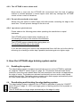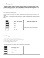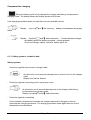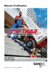
1
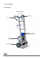
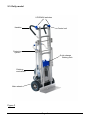
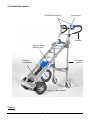
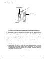
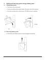
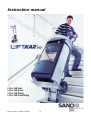
Instruction manual Liftkar HD Uni Liftkar HD Fold Liftkar HD Dolly Liftkar HD Fold Dolly Issued: 10/2010 – subject to updates. en Contents 1 INTRODUCTION AND KEY FEATURES ................................................ 3 1.1. 1.3 1.4. General safety guidelines ...................................................................................................... 3 Technical data LIFTKAR HD models .................................................................................... 5 Technical data of quick-change battery unit ....................................................................... 5 2. CONTROL FEATURES ........................................................................... 6 UNI model ............................................................................................................................... 6 Fold model .............................................................................................................................. 7 Dolly model ............................................................................................................................. 8 Fold Dolly model .................................................................................................................... 9 Control unit ........................................................................................................................... 10 ON/OFF and Single-step/Continuous mode multi-function switch (P).................................... 10 LED display ............................................................................................................................ 10 Speed switch .......................................................................................................................... 11 UP/DOWN switch on handlebar .......................................................................................... 12 Main switch ........................................................................................................................... 13 Switching off ......................................................................................................................... 13 2.1. 2.2. 2.3. 2.4. 2.5. 2.5.1. 2.5.2. 2.5.3. 2.6. 2.7. 2.8. 3. 3.1. 3.2. FITTING AND REMOVING QUICK-CHANGE BATTERY PACK ......... 13 Fitting battery pack .............................................................................................................. 14 Removing battery pack ........................................................................................................14 4. OPERATION.......................................................................................... 15 4.1. 4.2. 4.2.1. 4.2.2. 4.2.3. 4.2.4. Climbing UP stairs ............................................................................................................... 15 Climbing DOWN stairs ......................................................................................................... 15 Overload ................................................................................................................................. 15 The LIFTKAR is not a rubber mat! ......................................................................................... 16 Do not ride over kerbs at an angle ......................................................................................... 16 Operation on spiral staircases ................................................................................................ 16 5. HOW THE LIFTKAR EDGE BRAKING SYSTEM WORKS: ................. 16 5.1. 5.2. 5.3. Enabling the system: ........................................................................................................... 16 Deactivating and blocking the edge braking system: ...................................................... 16 Automatic switch-off after extended period of no operation ........................................... 17 6. 6.1. 6.1.1. 6.1.2. 6.1.3. 6.1.4. CHARGING THE QUICK-CHANGE BATTERY PACK ......................... 18 Charger unit .......................................................................................................................... 19 Testing the battery pack ......................................................................................................... 19 Charging ................................................................................................................................. 19 Safety systems - technical data .............................................................................................. 20 Safety regulations ................................................................................................................... 21 7. ACCESSORIES AND OPTIONS ........................................................... 22 8. 8.1. 8.2. WARRANTY AND PRODUCT LIABILITY ............................................ 22 Warranty ............................................................................................................................. 22 Liability ............................................................................................................................. 22 9. CE DECLARATION OF CONFORMITY ................................................ 23 10. PATENT REGISTERED ........................................................................ 23 Page 2 1 INTRODUCTION AND KEY FEATURES Congratulations! We would like to congratulate you on the purchase of your powered stairclimber truck type LIFTKAR HD. You have chosen a unit especially designed for carrying loads of up to 330 kg using the very latest stairclimber technology for negotiating different types of steps and stairs safely and efficiently. Development of the LIFTKAR HD focussed especially on user safety and user friendliness. Key features: Two UP / DOWN switches - one on the left and one on the right of the handle unit - for perfect user comfort. Ideal for both left- and right-handed operators. Automatic braking system that ensures the main wheels stop reliably at the edge of each step from the moment the unit is switched on. Optimum protection against impact to the support wheels thanks to a lubricated mechanical clutch. Additional electronic protection prevents damage due to overloading. 2 climbing speeds and two operating modes (single-step mode and continuous mode) to perfectly match your operating style. Excellent performance on spiral staircases. 1.1. General safety guidelines Make sure nobody is located underneath the load. Always secure the load with the safety belt included. Always wear non-slip shoes. Some steps may be very smooth. Always wear shoes with steel toecaps. The Liftkar may only be operated by trained personnel. Never reach into the unit's transport mechanism with your hands. Plan each journey on the stairs according to the current situation before you start. Always remove the battery pack before stowing the LIFTKAR. Firstly so the LIFTKAR cannot be switched on inadvertently during transport and secondly because the LIFTKAR is 4 kg lighter without the battery pack. Page 3 1.2 Built-in safety features (depending on model) Fold model: Each time before you use the stairclimber, make sure that the quick release lever (Figure 2, page 7) on the handles is tightened properly. It must be possible to tilt the load from the standing position without assistance. The position of the handle section in relation to the frame must not be altered. Dolly model: Figure A shows the protection system when retracted. Figure A shows the protection system when extended. The sliding arm must be at right-angles to the protection system. Sliding arm Protection system Sliding arm Protection system Figure B Figure A Each time before starting up the stairclimber, make sure that the protection system is properly folded away (retracted, Figure D). Figure C: folding away Figure D: support system retracted Important: Do not use the protection system in the extended position while operating the stairclimber on stairs. Page 4 1.3 Technical data LIFTKAR HD models Uni – Fold - Dolly Load capacity Maximum climbing speed with full load Maximum step height 330 kg 9-10 steps/min 210mm Model Weight (incl. Battery pack) HD UNI HD-Fold HD-Dolly HD-Fold-Dolly 38kg 39kg 44kg 45kg 1.4. Technical data of quick-change battery unit Fuse: internal blow-out fuse (30 Amp) Charging contact: DC jack dia. 2.1 x 9.5 mm Weight of battery: 4 kg Capacity: 5 Ah Voltage: 24 VDC (2x 12 VDC – 5 Ah) Type of battery: maintenance-free, leak-safe lead gel cell (approved by DOT and IATA for air freight) Page 5 2. Control features 2.1. UNI model UP/DOWN switches Control unit Handles Quick-change Battery pack Climbing mechanism Main wheels Figure 1 Page 6 2.2. Fold model UP/DOWN switches Handles Control unit Quick release Quick-change battery pack Climbing mechanism Main wheels Figure 2 Page 7 2.3. Dolly model UP/DOWN switches Handles Control unit Protection system Quick-change Battery pack Climbing mechanism Main wheels Figure 3 Page 8 2.4. Fold Dolly model UP/DOWN switches Control unit Handles Quick-change Battery pack Protection system Climbing mechanism Main wheels Figure 4 Page 9 2.5. Control unit Speed selector LED ON/OFF multifunction key P (Figure 5) 2.5.1. ON/OFF and Single-step/Continuous mode multi-function switch (P) The LIFTKAR is ready for operation after the battery pack has been switched on (ON/OFF switch on power pack) and you briefly press button P. This is confirmed by the green LED display on the control unit going on. The LIFTKAR is in Singlestep mode. If you briefly press button "P" again the unit switches to Continuous mode. This is signalled by the LED flashing green. Pressing the button for longer than 3 seconds switches the LIFTKAR off. 2.5.2. LED display Green light on: LIFTKAR is in Single-step mode. Pressing one of the UP/DOWN switches (see figure 6, page 12) starts the LIFTKAR moving. The unit switches off automatically after one climbing cycle has been completed (raising or lowering the LIFTKAR one step). Page 10 IMPORTANT: Keep pressing the UP/DOWN switch in Single-step mode until the LIFTKAR reaches the next step and stops automatically. Then release the switch. Pressing the switch again starts the LIFTKAR on its next movement cycle. If the switch is released by mistake during a cycle, simply press the UP/DOWN button again to continue the movement. The Liftkar continues operating until it reaches the end of the cycle and stops automatically. Releasing the button and pressing it again starts the next climbing cycle. Flashing green: The LIFTKAR is in Continuous mode. For users with plenty of practice. The LIFTKAR starts climbing when the UP/DOWN switch is pressed and doesn't stop until the UP/DOWN switch is released. Flashing red: The LIFTKAR is overloaded. (The LED flashes for approx. 3 seconds and then goes out – see also Operation section [4.2.1.], page 15) Alternating red and green: the battery pack is running low and urgently needs to be recharged. The stairclimber will certainly manage another flight of stairs, but we recommend that you move down stairs and either change the battery pack or fully recharge it before starting up the stairclimber again. 2.5.3. Speed switch Use the speed switch to select higher or lower climbing speeds. (Figure 5, page 10) The lower speed or single-step mode is recommended for beginners, heavy loads and difficult situations. Page 11 2.6. UP/DOWN switch on handlebar With an UP/DOWN switch located both on the left and right of the handlebar (Figure 6), this unit is ideal for both left- and right-handed operators. UP/DOWN switches DOWN UP Figure 6 (UP/DOWN switch) Page 12 2.7. Main switch The main switch is located on the quick-change battery pack. The power supply to the unit can be switched off safely using the main switch (Figure E). Figure E 2.8. Switching off The unit can be switched off in the following ways: Removing the quick-change battery pack (see section 3). Using the main switch on the quick-change battery pack (see figure E, 2.7). Pressing multi-function switch P for longer than 3 seconds. Leaving the unit for a period of time: The LIFTKAR switches off automatically after 10 minutes. Using the main switch or removing the battery pack provides a higher level of safety than switching off using switch P or leaving the unit to switch off automatically because switch P could easily be actuated inadvertently, causing the machine to switch on. Always switch off the main switch on the battery pack before stowing the unit away. Page 13 3. Fitting and removing quick-change battery pack 3.1. Fitting battery pack First position corner A in hook B. Gently press battery pack forwards swiftly. The battery pack clicks into place. Set switch on battery pack to ON and your LIFTKAR is ready for operation. Latches 3.2. Removing battery pack Lift the battery pack sharply upwards. It then disengages automatically. Page 14 4. Operation 4.1. Climbing UP stairs Fit battery pack, switch main switch to ON, press briefly on multi-function switch P until the LED display goes permanently green (Single-step mode, refer to section 2.5.1.), or flashes green (Continuous mode). The LIFTKAR is now ready for operation. Pressing one of the UP/DOWN switches Q (Figure 6, page 12, left and right of handlebar, arrow upwards points towards operator) starts moving the lift arm with the support wheels and lifts the LIFTKAR onto the next step. The cycle is repeated until the switch is released (Continuous mode, LED flashes green). In Single-step mode the LIFTKAR stops when the main wheels reach the next step. Important: As soon as the main wheels have "landed" on the next step, always draw the unit away from the edge of the step and contacts the step above. 4.2. Climbing DOWN stairs Fit battery pack, switch main switch to ON, press briefly on multi-function switch P until the LED display goes permanently green (Single-step mode, refer to section 2.5.1.), or flashes green (Continuous mode). The LIFTKAR is now ready for operation. Pressing one of the UP/DOWN switches Q (Figure 6, page 12, left and right of handlebar, arrow downwards points away from operator) starts moving the lift arm with the support wheels and lowers the LIFTKAR onto the next step. The cycle is repeated until the switch is released (Continuous mode, LED flashes green). In Single-step mode the LIFTKAR stops when the main wheels reach the next step. Important: As soon as the main wheels have landed on the step, always push the Liftkar to the edge of the next step. The brake wheels stop the Liftkar reliably on the edge of the step. 4.2.1. Overload If the unit is overloaded the drive motor stops and the LED flashes red for 3 seconds before going out. The unit has to be switched on again. If the power of the battery pack is running out then the overload signal will be displayed even on loads below the specified capacity. Page 15 4.2.2. The LIFTKAR is not a rubber mat! Never throw a load onto the LIFTKAR! We recommend that this kind of loading method is avoided because it causes higher wear and may damage the LIFTKAR control unit as a result of vibrations. 4.2.3. Do not ride over kerbs at an angle Always ride over kerbs or similar edges with both wheels contacting the edge at the same time. This will prevent damage to the drive unit. 4.2.4. Operation on spiral staircases Please observe the following points when operating the stairclimber on spiral staircases: The LIFTKAR moves inwards when climbing up, so: For climbing UP start on the outside of the staircase. The LIFTKAR moves outwards when going down, so: For climbing DOWN start on the inside. If you do start moving too close to the banisters/wall then shift the unit to the side by reversing (on a landing or wider step if possible) and start again at a tighter angle. 5. How the LIFTKAR edge braking system works: 5.1. Enabling the system: The edge braking system is enabled automatically as soon as the LIFTKAR is switched on using the "ON/OFF" switch (Figure 5, page 10). This ensures that the brake blocks inside the rims of the main wheels block the main wheels as soon as the unit approaches the edge of a step. The brakes are released mechanically as soon as the main wheels contact the next step. The brake system remains active and engages automatically when the main wheels approach the edge of the next step. 5.2. Deactivating and blocking the edge braking system: The edge braking system is blocked if the LIFTKAR is switched off using the "ON/OFF" switch (Figure 5, page 10 - LED is no longer green or flashing) and the unit is parked on its toe plate. The LIFTKAR then no longer stops automatically at the edge of a step. Page 16 NOTE: It is a good idea to deactivate the brake system on uneven ground because bumps or dips in the ground would otherwise cause the main wheels to be stopped if one of both of the edge brakes were activated. IMPORTANT: Make sure that the system is switched on again before starting each movement downwards to the next step. This is indicated by the LED changing to green or flashing green (see section 2.5.1. for operating modes). Only then is the edge braking system enabled. 5.3. Automatic switch-off after extended period of no operation Please note that the LIFTKAR switches off automatically to save the battery pack after approx. 10 min without the UP/DOWN switch being pressed). The edge braking system is also deactivated (providing the unit is parked on the toe plate). IMPORTANT: Always check the status of the LED when starting moving again after a pause (LED must be green or flashing green). Only then is the edge braking system engaged. NOTE: Do I have to make sure the edge braking system is activated on every step? No, you only have to approach the edge of the step. Hand width rule: It is enough to position the LIFTKAR roughly one hand width away from the edge of the step (distance between point main wheels contact step and edge of step, i.e. approx. 7 – 8 cm). Now you can start the next lifting cycle and the LIFTKAR will land safely on the next step. Page 17 6. Charging the quick-change battery pack The lead gel cells inside the battery pack are maintenance-free, gas-tight and rechargeable. Their service life depends largely on the charging/discharging cycles. For example, it is possible to partially discharge lead batteries 1000 times, drawing more than 200 times the full capacity of the battery, providing the battery is never fully discharged. Avoid discharging the battery completely. Charge the battery pack as often as possible. Lead batteries are susceptible to self-discharging. It is therefore necessary to recharge the quick-change battery pack after 3 weeks, even if it has not been in use. The charger unit supplied switches over automatically to compensation charging so it is not possible to over-charge the battery. Do not leave the quick-change battery pack discharged or half discharged. Always recharge the battery immediately. If the batteries should become damaged it is possible to have them replaced in any reputable mechanical workshop. The old lead batteries are fully recyclable and are not to be disposed of. The ideal temperature for charging is between 20 and 25° C. Temperatures that are too cold or too hot will affect the battery's capacity. If the battery pack is not fully charged, or it looses its charge suddenly, not only will the speed of the LIFTKAR be slower, but its capacity is reduced as well. This means that overload may be displayed even with a relatively light load. See Operation [4.2.1] Page 18 6.1. Charger unit The battery charger supplied is extremely powerful thanks to an automatic 2-stage system and digital control technology. The first stage is quick charging and the second stage is for maintaining the charge. You can also check whether the battery pack is charged or not. Features clear LCD display and pivoting mains adapter. 6.1.1. Testing the battery pack Simply connect the charger to the battery pack (without the charger being connected to the mains) After approx. 9 seconds one of the following test results is displayed (static voltage of battery pack) 100% - fully charged battery pack ready for use 80 % 50% 20% battery pack needs to be charged 0% - flat 6.1.2. Charging 1. 2. 3. 4. Connect the charger to the battery pack The static voltage of the battery pack is displayed Connect the charger to the mains The charging procedure starts The charging status of the battery pack is indicated by flashing bars: fully charged, 100 % approx. 80 % approx. 50 % 0-20% Page 19 Compensation charging When the battery pack is fully charged the charger switches go compensation charging mode. The display shows the battery symbol with 4 bars. If the charging procedure does not start there are two possible causes: Display: Symbols and flash alternately ... battery is connected the wrong way round Display: Symbols and flash alternately ... Contact between charger and battery pack has been interrupted - contact problem Check the charger cables, contacts, battery pack, etc. 6.1.3. Safety systems - technical data Safety systems - Protection against short-circuit in charger cable An electronic circuit prevents damage due to a short circuit in the charger cable. Display: the first bar flashes - Protection against connecting up the wrong way round An electronic circuit prevents damage due to the charger cable being connected the wrong way round. Display: Symbols and flash alternately - Protection against overheating As the ambient temperature increases the charger reduces the charging current or interrupts the charging procedure. The charging procedure starts again as soon as the temperature has decreased. Page 20 Safety shutdown The charger switches off if the battery pack has not reached a certain voltage within 4.5 hours. What to do after a safety shutdown: 1. Disconnect the charger from the mains 2. Disconnect the charger from the battery pack 3. Contact your sano dealer. Technical data Mains voltage supply (50/60 Hz, +/-15 %) 100-230 V AC Power draw (no load) max. 1.5 W Nominal rating 48 W Charging voltage 24 V DC Arithmetic charging current at 230 V / 50 Hz 2.0 A Protection class IP30 Safety shutdown after 4.5 h The function of the charger has been tested in the following conditions: - in a temperature range from -20°C to +50°C - at a humidity of 5-85 % Component specification: Climate class B 6.1.4. Safety regulations Use only for the purpose intended The charger unit is designed exclusively for charging lead cell batteries containing liquid, gel-type and fabric-type electrolyte. - It is not permissible to charge NiCd or NiMH batteries or primary cells. - Do not use the unit in the following circumstances: - if it is exposed to direct sunlight or is in a place where it could get wet or damp, or - if the cooling slots are obstructed. CE key-mark The charger fulfils the criteria laid down in the low-voltage and electromagnetic compatibility directive and is therefore CE-marked. Page 21 7. Accessories and options A full range of accessories and options is available. The list includes various sizes of toe plate, add-on toe plates with castors, safety belts, vehicle chargers for charging in transit, and much more. Please ask your dealer. 8. Warranty and product liability 8.1. Warranty The warranty period for the LIFTKAR is 12 months (6 months for battery packs) from the date of purchase and covers material flaws and manufacturing errors. The warranty does not include: 8.2. wear parts damage that occurs from using the unit for a purpose it was not intended forcible damage unauthorised modifications to the unit or accessories Liability SANO Transportgeräte GmbH is not responsible for the safety of the LIFTKAR if: the LIFTKAR is used for a purpose for which it is not intended. the LIFTKAR is not maintained regularly by a mechanical workshop. the instructions in this manual are not complied with. non-Sano components are fitted or linked to the LIFTKAR. original components are removed. Page 22 9. CE declaration of conformity SANO Transportgeraete GmbH declares that the LIFTKAR stairclimber fully complies with the relevant health and safety specifications laid down in the EU directive for machines 2006/42/EG, appendix IIA. Any changes made to the product without our prior consent render this declaration void. Jochum Bierma (Ing.), Managing Director 10. Patent registered The modular design of the base frame is legally protected by a patent. Page 23