1
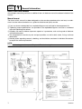
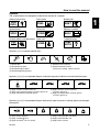
F200A
FL200A
SUPPLEMENTARY
SERVICE MANUAL
292087
60L-28197-3D-1X
NOTICE
This Supplementary Service Manual has been prepared to introduce new service and new data
information for the F200 and FL200 which is based on the F225 and FL225. For complete information on service procedures, it is necessary to use this Supplementary Service Manual together with
the following manual.
F225A, FL225A SERVICE MANUAL: 69J-28197-3D-11
Important information
1
Particularly important information is distinguished in this manual by the following notations:
The Safety Alert Symbol means ATTENTION! BECOME ALERT! YOUR SAFETY IS
INVOLVED!
WARNING
Failure to follow WARNING instructions could result in severe injury or death to the machine
operator, a bystander, or a person inspecting or repairing the outboard motor.
CAUTION:
A CAUTION indicates special precautions that must be taken to avoid damage to the outboard motor.
NOTE:
A NOTE provides key information to make procedures easier or clearer.
F200A, FL200A
SUPPLEMENTARY SERVICE MANUAL
©2001 by Yamaha Motor Co., Ltd.
1st Edition, August 2001
All rights reserved.
Any reprinting or unauthorized use
without the written permission of
Yamaha Motor Co., Ltd.
is expressly prohibited.
Printed in the Netherlands
Contents
General information
Specifications
Periodic checks and adjustments
Fuel system
Power unit
Lower unit
Bracket unit
GEN
INFO
SPEC
CHK
ADJ
FUEL
POWR
LOWR
BRKT
–
Electrical systems
Troubleshooting
Index
+
ELEC
TRBL
SHTG
1
2
3
4
5
6
7
8
9
General information
How to use this manual .................................................................................... 1
Manual format............................................................................................... 1
Symbols........................................................................................................ 2
Identification...................................................................................................... 3
Applicable models ........................................................................................ 3
Serial number ............................................................................................... 3
Features and benefits ....................................................................................... 4
Electronic control system.............................................................................. 4
Ignition and fuel injection timing ................................................................... 5
Technical tips .................................................................................................... 6
Fuel injection control..................................................................................... 6
Propeller selection ............................................................................................ 7
Propeller size................................................................................................ 7
Selection....................................................................................................... 7
Predelivery checks ........................................................................................... 8
Checking the fuel system ............................................................................. 8
Checking the gear oil.................................................................................... 8
Checking the engine oil ................................................................................ 8
Checking the battery..................................................................................... 8
Checking the outboard motor mounting height............................................. 9
Checking the remote control cables ............................................................. 9
Checking the steering wheel ...................................................................... 10
Checking the gearshift and throttle operation............................................. 10
Checking the tilt system.............................................................................. 10
Checking the engine start switch and engine stop switch/
engine shut-off switch ............................................................................... 10
Checking the cooling water pilot hole ......................................................... 11
Test run ...................................................................................................... 11
Break-in ...................................................................................................... 11
After test run ............................................................................................... 11
60L3D1X
Specifications
General specifications.................................................................................... 12
Maintenance specifications ........................................................................... 14
Power unit................................................................................................... 14
Lower unit ................................................................................................... 17
Electrical ..................................................................................................... 18
Dimensions................................................................................................. 21
Tightening torques.......................................................................................... 24
Specified torques........................................................................................ 24
General torques.......................................................................................... 27
Periodic checks and adjustments
Special service tools ...................................................................................... 27
Maintenance interval chart............................................................................. 28
Bracket unit
Power trim and tilt unit ................................................................................... 30
Assembling the gear pump......................................................................... 30
Electrical systems
Fuel control system ........................................................................................ 31
Checking the fuel injector ........................................................................... 31
Checking the low-pressure fuel pump and high-pressure fuel pump ......... 32
Troubleshooting
Yamaha Diagnostic System ........................................................................... 33
Introduction................................................................................................. 33
Getting started ............................................................................................ 33
Self-diagnosis.................................................................................................. 42
Diagnosing the electronic control system ................................................... 42
Index................................................................................................................. 44
Wiring diagram
60L3D1X
GEN
INFO
General information
How to use this manual
1
Only chapters containing revisions or additional items in the base manual have been included in this
manual.
Manual format
The format of this manual has been designed to make service procedures clear and easy to understand. Use the information below as a guide for effective and quality service.
1 Parts are shown and detailed in an exploded diagram and are listed in the components list.
2 Tightening torque specifications are provided in the exploded diagrams and after a numbered
step with tightening instructions.
3 Symbols are used to indicate important aspects of a procedure, such as the grade of lubricant
and lubrication point.
4 The components list consist of parts and part quantities, as well as bolt, screw, O-ring, and hose
dimensions.
5 Service points regarding removal, checking, and installation are shown in individual illustrations
to explain the relevant procedure.
NOTE:
For troubleshooting procedures, see Chapter 9, “Troubleshooting.”
1
60L3D1X
How to use this manual
Symbols
The symbols below are designed to indicate the content of a chapter.
General information
Fuel system
GEN
INFO
Bracket unit
FUEL
Specifications
BRKT
Power unit
SPEC
Electrical systems
POWR
ELEC
Periodic checks and adjustments Lower unit
CHK
ADJ
–
+
Troubleshooting
TRBL
SHTG
LOWR
Symbols 1 to 6 indicate specific data.
1
2
3
4
5
6
T.
R.
1
2
3
4
5 Specified measurement
6 Specified electrical value
(resistance, voltage, electric current)
Special tool
Specified oil or fluid
Specified engine speed
Specified tightening torque
Symbols 7 to A in an exploded diagram indicate the grade of lubricant and the lubrication point.
7
8
9
A
0
M
A
D
C
E
7 Apply Yamaha 4-stroke motor oil
8 Apply water resistant grease (Yamaha grease A)
9 Apply molybdenum disulfide grease
0 Apply corrosion resistant grease
(Yamaha grease D)
A Apply low temperature resistant grease
(Yamaha grease C)
Symbols B to G in an exploded diagram indicate the type of sealant or locking agent and the application point.
B
C
GM
D
4
B Apply Gasket Maker®
C Apply Yamabond No. 4
D Apply LOCTITE® No. 271 (Red)
60L3D1X
E
F
G
LT
LT
LT
271
242
572
SS
E Apply LOCTITE® No. 242 (Blue)
F Apply LOCTITE® No. 572
G Apply silicon sealant
2
1
2
3
4
5
6
7
8
9
GEN
INFO
General information
Identification
1
Applicable models
This manual covers the following models.
Applicable models
F200AET, FL200AET
Serial number
The outboard motor serial number is
stamped on a label attached to the port
clamp bracket.
1
2
3
4
3
Model name
Approved model code
Transom height
Serial number
Model name
Approved
model code
Starting
serial No.
F200AET
60L
X: 600101–
FL200AET
60M
X: 600101–
60L3D1X
Identification / Features and benefits
Features and benefits
1
Electronic control system
The ECM controls the ignition timing, the fuel injection timing, the fuel injection volume, and the ISC
and it maintains a stoichiometric air-fuel ratio in all operating conditions, including starting and idling.
Also, the ECM converts the signals from the input sensors and sends instructions to each part.
40
Pulser coil #1
15
39
Pulser coil #2
Pulser coil #3
14
38
Power source for intake air pressure sensor
TPS
Intake air presssure sensor
Ground for sensors
Engine temperature sensor
Intake air temperature sensor
18
12
21
11
19
Oil pressure sensor
22
8
Neutral switch
ISC motor B
ISC motor C
ISC motor D
Ignition coil #1,4
35
7
10
Ignition coil #2,5
E CM
29
9
24
23
Emergency engine stop switch
ISC motor A
33
43
Shift cutoff switch
Injector #3,6
34
44
Power source for oil pressure sensor
Injector #2,5
13
20
Power source for TPS
Injector #1,4
Ignition coil #3,6
Oil pressure warning lamp
Overheat warning lamp
4
27
Engine warning lamp
31
3
Buzzer
BZ
DES switch
1
Tachometer
T
6
Vacancy
25
Port bank
Thermo switch
Starboard bank
Ground for unit
Vacancy
37
32
17
Ground for power source
Diagnosis signal
Personal
computer
Power source
for diagnosis
lamp
Main switch
P
42
26
36
16
30
28
2
~
High-pressure fuel pump
Low-pressure fuel pump
P
Battery power source
Main relay
Rectifire/Regulator
Main relay
Battery
Connector pin position
44 43 42 41 40 39 38 37 36 35 34 33 32 31 30 29 28 27 26 25 24 23
22 21 20 19 18 17 16 15 14 13 12 11 10 9 8 7 6 5 4 3 2 1
S60L1180
60L3D1X
4
GEN
INFO
General information
Ignition and fuel injection timing
This engine adopted the group injection system that the fuel required for one combustion is injected
twice per one cycle.
Therefore, the injector driving circuits can be integrated to 3 circuits and a simpler electrical structure is obtained.
Firing order : #1, #2, #3, #4, #5, #6
Injection order : #1 and #4 → #2 and #5 → #3 and #6 (group injection)
: Ignition spark
: Wasted spark
Crankshaft angle
720˚
180˚
120˚
Cylinder
Cylinder #1
Ignition
Compression
TDC Combustion
Exhaust
Intake
Injection
Cylinder #2
Ignition
Compression
Intake
TDC Combustion
Exhaust
Injection
Cylinder #3
Ignition
Intake
Compression
TDC Combustion
Exhaust
Injection
Cylinder #4
Ignition
Compression
Intake
Exhaust
TDC Combustion
Injection
Cylinder #5
Ignition
Combustion
Exhaust
Compression
Intake
TDC
Injection
Cylinder #6
Ignition
Combustion
Exhaust
Intake
Compression
Injection
S60L1190
5
60L3D1X
Features and benefits / Technical tips
Technical tips
1
Fuel injection control
The F200 injects fuel simultaneously to the following cylinder pairs: #1 and #4, #2 and #5, and #3
and #6. Optimal injection timing is provided in accordance with the operating conditions of the
engine.
Starting fuel injection volume and injection timing
The injectors are actuated in sync with the standard crankshaft position signals (BTDC 70°) for cylinder pairs #1 and #4, #2 and #5, and #3 and #6, respectively.
#6
#1
#2
#3
#4
#5
#6
#1
#2
(Compression TDC)
CYLINDER #1
CYLINDER #2
CYLINDER #3
CYLINDER #4
CYLINDER #5
CYLINDER #6
Compression
Combustion
Exhaust
Intake
Compression
Expansion
Compression
Combustion
Exhaust
Intake
Compression
Intake
Intake
Compression
Combustion
Exhaust
Intake
Compression
Compression
Combustion
Exhaust
Intake
Intake
Exhaust
Intake
Combustion
Exhaust
Compression
Combustion
Exhaust
Intake
Combustion
Exhaust
Compression
Combustion
Exhaust
B70
B10
B70
B10
B70
B10
SIGNAL #1/4
B70
SIGNAL #2/5
SIGNAL #3/6
B10
B10
B70
B70
B10
B10
B70
B70
B10
B10
INJECTION #1/4
INJECTION #2/5
INJECTION #3/6
Starting injection start timing
(standard position BTDC 70˚)
S60L1200
Normal fuel injection volume and injection timing
To control the actuation timing of the injectors, the injection ending timing is established by using the
top-dead-center of the intake stroke as the standard, for cylinder pairs #1 and #4, #2 and #5, and #3
and #6, respectively.
#6
#1
#2
#3
#4
#5
#6
#1
#2
(Compression TDC)
CYLINDER #1
CYLINDER #2
CYLINDER #3
CYLINDER #4
CYLINDER #5
CYLINDER #6
Compression
Combustion
Exhaust
Intake
Compression
Expansion
Compression
Combustion
Exhaust
Intake
Compression
Intake
Intake
Combustion
Exhaust
Intake
Compression
Compression
Compression
Combustion
Exhaust
Intake
Intake
Exhaust
Intake
Combustion
Exhaust
Compression
Combustion
Exhaust
Intake
Combustion
Exhaust
Compression
Combustion
Exhaust
B70
B10
B70
B10
B70
B10
SIGNAL #1/4
B70
SIGNAL #2/5
SIGNAL #3/6
B10
B10
B70
B70
B10
B10
B70
B70
B10
B10
INJECTION #1/4
INJECTION #2/5
INJECTION #3/6
Synchronous injection completion timing
#1/4 synchronous injection start/completion
timing setting range
60L3D1X
S60L1210
6
GEN
INFO
General information
Propeller selection
1
The performance of a boat and outboard
motor will be critically affected by the size
and type of propeller you choose. Propellers
greatly affect boat speed, acceleration,
engine life, fuel economy, and even boating
and steering capabilities. An incorrect choice
could adversely affect performance and
could also seriously damage the engine.
Use the following information as a guide for
selecting a propeller that meets the operating
conditions of the boat and the outboard
motor.
a Propeller diameter (in inches)
b Propeller pitch (in inches)
c Propeller type (propeller mark)
Selection
When the engine speed is at the full throttle
operating range (5,000–6,000 r/min), the
ideal propeller for the boat is one that provides maximum performance in relation to
boat speed and fuel consumption.
Regular rotation model
Propeller size (in)
Material
13 3/4 × 17 - M
13 3/4 × 19 - M
Propeller size
The size of the propeller is indicated on the
propeller blade or outside of the propeller
boss.
13 3/4 × 21 - M
14 1/2 × 15 - M
14 1/2 × 19 - T
14 1/2 × 21 - T
14 7/8 × 21 - M
×
-
Stainless
14 7/8 × 23 - M
15 × 17 - T
15 1/4 × 15 - M
15 1/4 × 17 - M
15 1/4 × 19 - M
S60L1030
Counter rotation model
Propeller size (in)
Material
13 3/4 × 17 - ML
×
13 3/4 × 19 - ML
-
13 3/4 × 21 - ML
14 1/2 × 15 - ML
14 1/2 × 19 - TL
S60L1040
14 1/2 × 21 - TL
14 7/8 × 21 - ML
Stainless
14 7/8 × 23 - ML
15 × 17 - TL
15 1/4 × 15 - ML
×
15 1/4 × 17 - ML
-
15 1/4 × 19 - ML
S60L1050
7
60L3D1X
Propeller selection / Predelivery checks
Predelivery checks
1
To make the delivery process smooth and
efficient, the predelivery checks should be
completed as explained below.
Checking the engine oil
1. Check the oil level.
Checking the fuel system
1. Check that the fuel hoses are securely
connected and that the fuel tank is full
with fuel.
NOTE:
• If the engine oil is above the maximum level
mark (H), drain sufficient oil until the level is
between (H) and (L).
• If the engine oil is below the minimum level
mark (L), add sufficient oil until the level is
between (H) and (L).
S60L1060
CAUTION:
This is a 4-stroke engine. Do not use premixed fuel and 2-stroke outboard motor
oil.
Checking the gear oil
Recommended engine oil:
4-stroke motor oil
API: SE, SF, SG, or SH
SAE: 10W-30 or 10W-40
Oil capacity:
Without oil filter replacement:
5.8 L (6.1 US qt, 5.1 Imp qt)
Checking the battery
1. Check the capacity, electrolyte level, and
specified gravity of the battery.
Battery capacity: 12 V–100 Ah
1. Check the gear oil level.
2. Check that the red and black battery
cables are securely connected.
S60L1070
60L3D1X
8
GEN
INFO
General information
Checking the outboard motor
mounting height
1. Check that the anti-cavitation plate is
aligned with the bottom of the boat. If the
mounting height is too high, cavitation
will occur and propulsion will be reduced.
Also, the engine speed will increase
abnormally and cause the engine to
overheat. If the mounting height is too
low, water resistance will increase and
reduce engine efficiency.
3. Check that the set pin c is in the center
of the shift bracket and aligned with the
alignment mark d on the bracket.
NOTE:
The optimum mounting height is affected by
the combination of the boat and the outboard
motor. To determine the optimum mounting
height, test run the outboard motor at different heights.
2. Check that the clamp brackets are
secured with the clamp bolts.
S60L1120
Checking the remote control cables
1. Set the remote control lever to the neutral position and fully close the throttle
lever.
2. Check that the throttle cam 1 is in its
fully close position and the alignment
mark a is between the alignment mark
b.
9
CAUTION:
The shift/throttle cable joint must be
screwed in a minimum of 8.0 mm (0.31 in)
e.
60L3D1X
Predelivery checks
Checking the steering wheel
Checking the tilt system
1. Check the steering friction for proper
adjustment.
1. Check that the outboard motor tilts up
and down smoothly when operating the
power trim and tilt unit.
2. Check that
smoothly.
the
steering
operates
2. Check that there is no abnormal noise
produced when the outboard motor is
tilted up or down.
3. Check that there is no interference with
wires and hoses when the tilted-up outboard motor is steered.
4. Check that the trim meter points down
when the outboard motor is tilted all the
way down.
3. Check that there is no interference with
wires or hoses when the outboard motor
is steered.
Checking the gearshift and throttle
operation
1. Check that the gearshift operates
smoothly when the remote control lever
is shifted from neutral into forward or
reverse.
2. Check that the throttle operates smoothly
when the remote control lever is shifted
from the fully closed position to the fully
open position a.
Checking the engine start switch and
engine stop switch/engine shut-off
switch
1. Check that the engine starts when the
engine start switch is turned to START.
2. Check that the engine turns off when the
engine start switch is turned to OFF.
3. Check that the engine turns off when the
engine shut-off cord is pulled from the
engine shut-off switch.
N
F
R
S60L1150
S60L1140
60L3D1X
10
GEN
INFO
General information
Checking the cooling water pilot
hole
1. Start the engine, and then check that
cooling water is discharged from the
cooling water pilot hole.
0
1
2
10
S60L1170
È Hour
After test run
1. Check for water in the gear oil.
S60L1160
Test run
1. Start the engine, and then check that the
gearshift operates smoothly.
2. Check for fuel leakage in the cowling.
3. After a test run and while the engine is at
idle, flush the cooling water passage with
fresh water using the flushing kit.
2. Check the engine idle speed after the
engine has been warmed up.
3. Operate at trolling speed.
4. Run the outboard motor for one hour at
2,000 r/min or at half throttle, then for
another hour at 3,000 r/min or at 3/4
throttle.
5. Check that the outboard motor does not
tilt up when shifting into reverse and that
water does not flow in over the transom.
NOTE:
The test run is part of the break-in operation.
Break-in
During the test run, perform the break-in
operation in the following three stages.
1. One hour a at 2,000 r/min or at approximately half throttle.
2. One hour b at 3,000 r/min or 3/4 throttle
and one minute out of every ten at full
throttle.
3. Eight hours c at any speed, however,
avoid running at full speed for more than
five minutes.
11
60L3D1X
Predelivery checks / General specifications
General specifications
Item
Dimension
Overall length
Overall width
Overall height
(X)
Boat transom height
(X)
Weight(*1)
(X)
Performance
Maximum output
Full throttle operating range
Maximum fuel consumption
Power unit
Type
Cylinder quantity
Displacement
Bore × stroke
Compression ratio
Control system
Starting system
Ignition control system
Ignition timing
Alternator output
Spark plugs
Cooling system
Exhaust system
Lubrication system
2
Unit
Model
F200AET
FL200AET
mm (in)
mm (in)
892 (35.1)
634 (25.0)
mm (in)
1,805 (71.1)
mm (in)
635 (25.0)
kg (lb)
269 (593)
kW (hp)
at 5,500 r/min
r/min
L (US gal,
lmp gal)/hr
at 6,000 r/min
147.1 (200)
cm3 (cu. in)
mm (in)
Degree
V, A
1
2
3
4
5
6
7
8
9
5,000–6,000
66.0 (17.4, 14.5)
V6, 4-stroke, DOHC, 24 valves
6
3,352 (204.5)
94.0 × 80.5 (3.70 × 3.17)
9.9
Remote control
Electric
Microcomputer (TCI)
TDC–BTDC 21
12, 45
LFR5A-11 (NGK)
Water
Through propeller boss
Wet sump
(*1) Includes a stainless propeller and excludes oil, battery cables and rigging parts.
60L3D1X
12
SPEC
Specifications
Item
Fuel and oil
Fuel type
Fuel rating
Engine oil type
Engine oil grade
Unit
PON*
RON
API
SAE
Model
F200AET
Regular unleaded gasoline
86
91
4-stroke motor oil
SE, SF, SG, or SH
10W-30 or 10W-40
Engine oil quantity
(with oil filter replacement)
L
(US qt, lmp qt)
(without oil filter replacement)
L
(US qt, lmp qt)
Gear oil type
Gear oil grade
API
SAE
Gear oil quantity
L
(US qt, lmp qt)
Bracket
Trim angle
Degree
(at 12 degree boat transom)
Tilt-up angle
Degree
Steering angle
Degree
Drive unit
Gearshift positions
Gear ratio
Reduction gear type
Clutch type
Propeller shaft type
Propeller direction
(rear view)
Propeller identification mark
Electrical
Battery capacity
V–Ah
FL200AET
6.0 (6.3, 5.3)
5.8 (6.1, 5.1)
Hypoid gear oil
GL-4
90
1.15 (1.22, 1.01)
1.00 (1.06, 0.88)
–3–16
70
32 + 32
F-N-R
2.00 (30/15)
Spiral bevel gear
Dog clutch
Spline
Clockwise
Counterclockwise
T, M
TL, ML
12–100
* PON: Pump Octane Number = (Research Octane Number + Motor Octane Number)/2
RON: Research Octane Number
13
60L3D1X
General specifications / Maintenance specifications
Maintenance specifications
2
Power unit
Item
Power unit
Minimum compression
pressure*
Lubrication oil pressure
Cylinder heads
Warpage limit
(lines indicate straightedge
position)
Camshaft cap inside diameter
Cylinders
Bore size
Taper limit
Out-of-round limit
Pistons
Piston diameter (D)
Measuring point (H)
Piston-to-cylinder clearance
Piston pin boss bore
Piston pins
Outside diameter
Piston rings
Top ring
Dimension B
Dimension T
End gap
Side clearance
2nd ring
Dimension B
Dimension T
End gap
Side clearance
Unit
Model
F200AET
FL200AET
kPa
(kgf/cm2, psi)
kPa (kgf/cm2,
psi) at
700 r/min
880 (8.8, 125)
mm (in)
0.1 (0.004)
mm (in)
25.00–25.02 (0.9843–0.9850)
mm (in)
mm (in)
mm (in)
94.00–94.02 (3.7008–3.7016)
0.05 (0.0020)
0.01 (0.0004)
mm (in)
mm (in)
mm (in)
mm (in)
93.921–93.941 (3.6977–3.6985)
5 (0.2)
0.075–0.080 (0.0029–0.0031)
21.02–21.03 (0.8276–0.8280)
mm (in)
21.00 (0.827)
mm (in)
mm (in)
mm (in)
mm (in)
1.17–1.19 (0.0461–0.0468)
2.8–3.0 (0.110–0.118)
0.15–0.30 (0.0059–0.0118)
0.04–0.08 (0.0016–0.0031)
mm (in)
mm (in)
mm (in)
mm (in)
1.17–1.19 (0.0461–0.0468)
3.6–3.8 (0.142–0.150)
0.30–0.45 (0.0118–0.0177)
0.03–0.07 (0.0012–0.0027)
650 (6.5, 924)
* Measuring conditions:
Ambient temperature 20 °C (68 °F), wide open throttle, with plugs disconnected from all cylinders.
The figures are for reference only.
60L3D1X
14
SPEC
Specifications
Item
Oil ring
Dimension B
Dimension T
End gap
Side clearance
Camshafts
Intake (A)
Exhaust (A)
Intake and
exhaust (B)
Camshaft journal diameter
Camshaft journal oil clearance
Camshaft runout limit
Valves
Valve clearance (cold)
Intake
Exhaust
Head diameter (A)
Intake
Exhaust
Face width (B)
Intake
Exhaust
Seat contact width (C)
Intake
Exhaust
Margin thickness (D)
Intake
Exhaust
Stem diameter
Intake
Exhaust
Guide inside diameter
Intake and exhaust
Stem-to-guide clearance
Intake
Exhaust
Stem runout limit
Valve springs
Free length
Minimum free length
Tilt limit
15
Unit
Model
F200AET
FL200AET
mm (in)
mm (in)
mm (in)
mm (in)
2.40–2.47 (0.0945–0.0972)
2.3–2.7 (0.091–0.106)
0.15–0.60 (0.0059–0.0236)
0.04–0.13 (0.0016–0.0051)
mm (in)
mm (in)
mm (in)
45.30–45.40 (1.7835–1.7874)
45.35–45.45 (1.7854–1.7894)
35.95–36.05 (1.4154–1.4193)
mm (in)
mm (in)
mm (in)
24.96–24.98 (0.9827–0.9834)
0.02–0.06 (0.0008–0.0023)
0.1 (0.004)
mm (in)
mm (in)
0.20 ± 0.03 (0.008 ± 0.001)
0.34 ± 0.03 (0.013 ± 0.001)
mm (in)
mm (in)
34.85–35.15 (1.3720–1.3839)
29.85–30.15 (1.1752–1.1870)
mm (in)
mm (in)
2.11 (0.0831)
2.43 (0.0957)
mm (in)
mm (in)
1.1–1.4 (0.043–0.055)
1.4–1.7 (0.055–0.067)
mm (in)
mm (in)
0.7 (0.028)
1.0 (0.039)
mm (in)
mm (in)
5.477–5.492 (0.2156–0.2162)
5.464–5.479 (0.2151–0.2157)
mm (in)
5.51–5.52 (0.2169–0.2173)
mm (in)
mm (in)
mm (in)
0.01–0.02 (0.0004–0.0008)
0.01–0.02 (0.0004–0.0008)
0.01 (0.0004)
mm (in)
mm (in)
mm (in)
44.20 (1.740)
42.60 (1.677)
1.5 (0.06)
60L3D1X
Maintenance specifications
Item
Valve lifters
Valve lifter outside diameter
Valve lifter-to-cylinder head
clearance
Valve shims
Valve shim thickness
(in 0.020 mm increments)
Connecting rods
Small-end inside diameter
Big-end inside diameter
Crankpin oil clearance
Big-end bearing thickness
Yellow
Green
Blue
Crankshaft
Crankshaft journal diameter
Crankpin diameter
Crankpin width
Runout limit
Crankcase
Crankshaft main journal oil
clearance
Upper crankcase main journal
bearing thickness
1
2
3
Lower crankcase main journal
bearing thickness
1
2
3
#3 main journal bearing
thickness (lower)
1
2
3
60L3D1X
Unit
Model
F200AET
FL200AET
mm (in)
mm (in)
32.98–33.00 (1.2984–1.2992)
0.02–0.05 (0.0008–0.0020)
mm (in)
2.320–2.960 (0.0913–0.1165)
mm (in)
mm (in)
mm (in)
21.00 (0.827)
53.00 (2.087)
0.035–0.071 (0.0014–0.0028)
mm (in)
mm (in)
mm (in)
1.492–1.496 (0.0587–0.0588)
1.496–1.500 (0.0588–0.0591)
1.500–1.504 (0.0591–0.0592)
mm (in)
mm (in)
mm (in)
mm (in)
62.968–62.992 (2.4791–2.4800)
49.976–50.000 (1.9676–1.9685)
21.50–21.55 (0.8465–0.8484)
0.03 (0.0012)
mm (in)
0.025–0.050 (0.0010–0.0020)
mm (in)
mm (in)
mm (in)
2.494–2.500 (0.0981–0.0984)
2.498–2.504 (0.0983–0.0986)
2.502–2.508 (0.0985–0.0987)
mm (in)
mm (in)
mm (in)
2.494–2.500 (0.0981–0.0984)
2.498–2.504 (0.0983–0.0986)
2.502–2.508 (0.0985–0.0987)
mm (in)
mm (in)
mm (in)
2.492–2.500 (0.0980–0.0984)
2.496–2.504 (0.0982–0.0986)
2.500–2.508 (0.0984–0.0987)
16
SPEC
Specifications
Item
Oil pump
Discharge
at 97–103 °C (207–217 °F)
with 10W-40 engine oil
Pressure
Relief valve opening pressure
Thermostats
Opening temperature
Fully open temperature
Valve open lower limit
Engine speed
Engine idle speed
Unit
L (US gal,
Imp gal)/min
at 700 r/min
kPa
(kgf/cm2, psi)
kPa
(kgf/cm2, psi)
Model
F200AET
FL200AET
8.8 (2.32, 1.94)
138 (1.38, 19.62)
529–647 (5.29–6.47, 75.22–92.00)
°C (°F)
°C (°F)
mm (in)
60 (140)
70 (158)
4.3 (0.17)
r/min
650–750
Lower unit
Item
Unit
Gear backlash
Pinion-to-forward gear
mm (in)
Pinion-to-reverse gear
mm (in)
Pinion shims
Forward gear shims
Reverse gear shims
Propeller shaft shims
mm
mm
mm
mm
17
Model
F200AET
FL200AET
0.21–0.44
0.35–0.70
(0.008–0.017)
(0.014–0.028)
0.70–1.03
0.70–1.03
(0.028–0.041)
(0.028–0.041)
0.10, 0.12, 0.15, 0.18, 0.30, 0.40, 0.50
0.10, 0.12, 0.15, 0.18, 0.30, 0.40, 0.50
0.10, 0.12, 0.15, 0.18, 0.30, 0.40, 0.50
—
0.10, 0.12, 0.15, 0.18,
0.30, 0.40, 0.50
60L3D1X
Maintenance specifications
Electrical
Item
Ignition and ignition control
system
Ignition timing
(engine idle speed)
Pulser coil output peak voltage
(W/R – B, W/B – B, W/G – B)
at cranking (unloaded)
at cranking (loaded)
at 1,500 r/min (loaded)
at 3,500 r/min (loaded)
Pulser coil resistance(*1)
(W/R – B, W/B – B, W/G – B)
ECM output peak voltage
(B/O – B, B/Y – B, B/W – B)
at cranking (loaded)
at 1,500 r/min (loaded)
at 3,500 r/min (loaded)
Spark plug gap
Ignition coil resistance
Primary coil
(R/Y – B/O,
R/Y – B/Y, R/Y – B/W)
Secondary coil
(spark plug wire –
spark plug wire)
Throttle position sensor output
voltage
(P – B)
Oil pressure sensor output
voltage (engine idle speed)
(O – B)
Intake air temperature sensor
resistance
at 0 °C (32 °F)
at 80 °C (176 °F)
Engine temperature sensor
resistance
(B/Y – B)
at 20 °C (68 °F)
at 100 °C (212 °F)
Thermoswitch continuity
temperature
(P – B)
ON
OFF
(*1)
Unit
Model
F200AET
FL200AET
Degree
TDC
V
V
V
V
Ω
5.3
5.3
20
43
459–561
V
V
V
mm (in)
252
260
260
1.1 (0.043)
Ω
1.5–1.9
kΩ
19.6–35.4
mV
695–705
V
3.8
kΩ
kΩ
5.4–6.6
0.29–0.39
kΩ
kΩ
54.2–69.0
3.12–3.48
°C (°F)
°C (°F)
84–90 (183–194)
68–82 (154–179)
The figures are for reference only.
60L3D1X
18
SPEC
Specifications
Item
Fuel control system
Fuel injector output peak
voltage(*1)
(R/Y – O/R, R/Y – O/B, R/Y – O/Y,
R/Y – O/R, R/Y – O/B, R/Y – O/Y)
at 1,500–3,000 r/min (loaded)
Fuel injector resistance(*1)
at 20 °C (68 °F)
Starter motor
Type
Output
Cranking time limit
Brushes
Standard length
Wear limit
Commutator
Standard diameter
Wear limit
Mica
Standard undercut
Wear limit
Charging system
Fuse
Stator coil output peak voltage
(G – G)
at cranking (unloaded)
at 1,500 r/min (unloaded)
at 3,500 r/min (unloaded)
(G/W – G/W)
at cranking (unloaded)
at 1,500 r/min (unloaded)
at 3,500 r/min (unloaded)
Stator coil resistance(*1)
(G – G)
(G/W – G/W)
Rectifier Regulator output
peak voltage (R – B, R/Y – B)
at 1,500 r/min (unloaded)
at 3,500 r/min (unloaded)
(*1)
19
Unit
Model
F200AET
FL200AET
V
38–40
Ω
14.0–15.0
kW
Second
Sliding gear
1.4
30
mm (in)
mm (in)
15.5 (0.61)
9.5 (0.37)
mm (in)
mm (in)
29.0 (1.14)
28.0 (1.10)
mm (in)
mm (in)
0.5–0.8 (0.02–0.03)
0.2 (0.01)
A
5, 20, 30
V
V
V
10
42
93
V
V
V
9.0
34
78
Ω
Ω
0.24–0.41
0.21–0.30
V
V
13
13
The figures are for reference only.
60L3D1X
Maintenance specifications
Item
Power trim and tilt system
Trim sensor
Setting resistance
Resistance
(P – B)
Fluid type
Brushes
Standard length
Wear limit
Commutator
Standard diameter
60L3D1X
Unit
Model
F200AET
FL200AET
Ω
Ω
9–11
9–387.6
ATF Dexron II
mm (in)
mm (in)
12.0 (0.47)
4.0 (0.16)
mm (in)
25.0 (0.98)
20
SPEC
Specifications
Dimensions
Exterior
W5
T1
A1
W1
L7
L6
L2
L1
L10
H9
H2
H7
H8
H10
H4
H1
L8
C3
A2
L5
H6
H3
12˚
A3
H11
L9
L4
S60L2130
21
60L3D1X
Maintenance specifications
Symbol
L1
L2
L3
L4
L5
L6
L7
L8
L9
L10
H1
H2
H3
H4
H5
H6
H7
H8
H9
H10
H11
W1
W2
W3
W4
W5
W6
A1
A2
A3
T1
60L3D1X
Unit
(X)
(X)
(X)
(X)
(X)
(X)
(X)
mm (in)
mm (in)
mm (in)
mm (in)
mm (in)
mm (in)
mm (in)
mm (in)
mm (in)
mm (in)
mm (in)
mm (in)
mm (in)
mm (in)
mm (in)
mm (in)
mm (in)
mm (in)
mm (in)
mm (in)
mm (in)
mm (in)
mm (in)
mm (in)
mm (in)
mm (in)
mm (in)
Degree
Degree
Degree
mm (in)
Model
F200AET
FL200AET
651 (25.6)
219 (8.6)
—
673 (26.5)
59 (2.3)
1,155 (45.5)
618 (24.3)
230 (9.1)
52 (2.0)
75 (3.0)
1,078 (42.4)
727 (28.6)
216 (8.5)
643 (25.3)
—
847 (33.3)
361 (14.2)
39 (1.5)
880 (34.6)
45 (1.8)
25 (1.0)
317 (12.5)
—
—
—
453 (17.8)
—
32
70
3
724 (28.5)
22
SPEC
Specifications
Clamp bracket
B5
B3
B4
B9
B9
B9
D1
C3
B2
B6
D2
B1
Symbol
B1
B2
B3
B4
B5
B6
B7
B8
B9
C2
C3
D1
D2
23
D1
S60L2140
Unit
mm (in)
mm (in)
mm (in)
mm (in)
mm (in)
mm (in)
mm (in)
mm (in)
mm (in)
mm (in)
mm (in)
mm (in)
mm (in)
Model
F200AET
FL200AET
125 (4.9)
254 (10.0)
163 (6.4)
51 (2.0)
180 (7.1)
411 (16.2)
—
—
19 (0.7)
—
79 (3.1)
13 (0.5)
56 (2.2)
60L3D1X
Maintenance specifications / Tightening torques
Tightening torques
2
Specified torques
Part to be tightened
Thread size
Fuel system
Fuel filter holder bolt
Fuel filter bracket bolt
Intake air temperature sensor
Low-pressure fuel pump bracket bolt
Fuel cooler nut
Float chamber bracket bolt
High-pressure fuel pump relay nut
Vapor separator cover screw
Link rod nut
Magnet control lever joint
Throttle cam bolt
Power unit
PTT motor lead bolt
Upper case cover bolt
Apron bolt
Power unit bolt
Flywheel magnet nut
PTT relay nut
Starter relay lead bolt
Battery cable nut
Starter motor bolt
Rectifier Regulator
1st
2nd
Link rod nut
Oil pressure sensor
Oil filter union bolt
Oil filter
Driven sprocket bolt
Timing belt tensioner bolt
Drive sprocket bolt
Cylinder head cover plate screw
Cylinder head cover bolt
Camshaft cap bolt
Exhaust cover bolt
Exhaust outer cover bolt
Exhaust outer cover plug
60L3D1X
M6
M6
—
M5
—
M8
—
M4
—
—
—
8
8
4
5
5
7
3
2
4
4
8
0.8
0.8
0.4
0.5
0.5
0.7
0.3
0.2
0.4
0.4
0.8
5.8
5.8
2.9
3.6
3.6
5.1
2.1
1.4
2.9
2.9
5.8
M6
M6
M6
M9 • M10
—
—
M6
—
M8
4
8
8
42
240
4
4
9
29
6
12
4
18
34
18
60
39
7
2
8
8
8
17
6
12
14
28
55
0.4
0.8
0.8
4.2
24
0.4
0.4
0.9
2.9
0.6
1.2
0.4
1.8
3.4
1.8
6.0
3.9
0.7
0.2
0.8
0.8
0.8
1.7
0.6
1.2
1.4
2.8
5.5
2.9
5.8
5.8
30
174
2.9
2.9
6.5
21
4.3
8.7
2.9
13
25
13
43
28
5.1
1.4
5.8
5.8
5.8
12
4.3
8.7
10
20
40
M6
—
—
—
—
M10
—
M5
M4
1st
2nd
1st
2nd
1st
2nd
1st
2nd
Tightening torques
N·m
kgf·m
ft·lb
M6
M7
M6
M8
M18
24
SPEC
Specifications
Part to be tightened
Thread size
Timing chain tensioner bolt
Spark plug
Cylinder head bolt
M6
—
1st
2nd
3rd
1st
2nd
Engine hanger bolt
Cooling water cover bolt
Starboard cylinder head plug
Cylinder block plug
Engine temperature sensor
Connecting rod cap
1st
2nd
3rd
Crankcase bolt
Lower unit (regular rotation model)
Trim tab bolt
Lower unit bolt
Propeller nut
Propeller shaft housing grease nipple
Propeller shaft housing bolt
Pinion nut
Lower unit (counter rotation model)
Trim tab bolt
Lower unit bolt
Propeller nut
Ring nut
Propeller shaft housing bolt
Propeller shaft housing grease nipple
Pinion nut
Bracket unit
Shift rod detent bolt
Flushing hose adapter screw
25
—
—
1st
2nd
Crankcase cover plate screw
Oil pump screw
Crankcase stud bolt
M8
M6
M6
—
—
—
Baffle plate nut
Crankcase cover bolt
M10
M8
M4
—
1st
2nd
1st
2nd
1st
2nd
M8
M10
M8
Tightening torques
N·m
kgf·m
ft·lb
12
1.2
8.7
25
2.5
18
19
1.9
14
37
3.7
27
90°
14
1.4
10
28
2.8
20
12
1.2
8.7
12
1.2
8.7
23
2.3
17
23
2.3
17
15
1.5
11
23
2.3
17
48
4.8
35
90°
12
1.2
8.7
14
1.4
10
28
2.8
20
2
0.2
1.4
4
0.4
2.9
25
2.5
18
90°
40
4.0
29
90°
14
1.4
10
28
2.8
20
M10
M10
—
—
M8
—
43
47
55
6
30
142
4.3
4.7
5.5
0.6
3.0
14.2
31
34
40
4.3
22
103
M10
M10
—
—
M8
—
—
43
47
55
108
30
6
142
4.3
4.7
5.5
10.8
3.0
0.6
14.2
31
34
40
78
22
4.3
103
—
M6
18
5
1.8
0.5
13
3.6
60L3D1X
Tightening torques
Part to be tightened
Upper case mount nut
Engine oil drain bolt
Apron stay
Pressure control valve
Upper exhaust guide bolt
Oil strainer bolt
Oil pan bolt
Exhaust manifold bolt
Muffler bolt
Baffle plate screw
Clamp bracket self-locking nut
Friction plate screw
Trim stopper nut
Power trim and tilt unit
Power trim and tilt unit bolt
Reservoir bolt
Reservoir cap
Manual valve
Fluid pipe
Trim cylinder end screw
Trim piston bolt
Tilt ram
Tilt cylinder end screw
Tilt piston bolt
Gear housing bolt
Gear housing bracket bolt
60L3D1X
—
M14
—
—
M8
M10
M6
M8
M8
M8
M6
—
M6
—
Tightening torques
N·m
kgf·m
ft·lb
72
7.2
52
27
2.7
19
8
0.8
5.8
8
0.8
5.8
20
2.0
14
42
4.2
30
10
1.0
7.2
20
2.0
14
20
2.0
14
20
2.0
14
4
0.4
2.9
22
2.2
16
4
0.4
2.9
36
3.6
25
M10
M8
M12
—
—
—
M8
—
—
M6
M5
M5
44
18
7
2
15
160
38
55
90
7
7
7
Thread size
4.4
1.8
0.7
0.2
1.5
16
3.8
5.5
9.0
0.7
0.7
0.7
32
13
5.1
1.4
11
115
27
40
65
5.1
5.1
5.1
26
SPEC
Specifications
Special service tools
General torques
This chart specifies tightening torques for
standard fasteners with a standard ISO
thread pitch. Tightening torque specifications
for special components or assemblies are
provided in applicable sections of this manual. To avoid warpage, tighten multi-fastener
assemblies in a crisscross fashion and progressive stages until the specified torque is
reached. Unless otherwise specified, torque
specifications require clean, dry threads.
Components should be at room temperature.
Nut (A)
Bolt (B)
8 mm
10 mm
12 mm
14 mm
17 mm
M5
M6
M8
M10
M12
27
General torque
specifications
N·m kgf·m ft·lb
5
0.5
3.6
8
0.8
5.8
18
1.8
13
36
3.6
25
43
4.3
31
2
Test harness (2 pins)
90890-06861
Diagnostic flash indicator 4
90890-06795
60L3D1X
Tightening torques / Special service tools / Maintenance interval chart
Maintenance interval chart
3
Use the following chart as a guideline for general maintenance.
Adjust the maintenance intervals according to the operating conditions of the outboard motor.
Top cowling
Top cowling fit
Fuel system
Fuel joint and fuel hoses
Fuel filter (disposable type)
Fuel filter (water separator)
Fuel tank(*1)
Power unit
Engine oil
Oil filter
Oil pump
Timing chain
Chain tensioner
Timing belt(*2)
Valve clearance
Spark plugs
Thermostat
Pressure control valve
Flywheel magnet nut
Motor exterior
Oil leakage
Cooling water passage(*3)
Control system
Throttle link
Throttle cable
Shift cable
Engine idle speed
Ignition timing
Power trim and tilt unit
Power trim and tilt unit
60L3D1X
Check
(before each use)
Check
Check/replace
Check
Clean
(before each use)
Check
Change
Change
Check
Check/replace
Check/replace
Check/replace
Check/adjust
Clean/adjust/replace
Check
Check
Check
Check
Check
Clean
400 hours
(2 years)
200 hours
(1 year)
100 hours
(6 months)
Remarks
Every
50 hours
(3 months)
Item
10 hours
(Break-in)
Initial
(before each use)
(before each use)
(1,000 hours or
5 years)
(before each use)
(after each use)
Check/adjust
Check/adjust
Check/adjust
Adjust
Check
Check
28
1
2
3
4
5
6
7
8
9
CHK
ADJ
Periodic checks and adjustments
Lower unit
Gear oil
Impeller/Woodruff key
Oil seals
Propeller
General
Anodes/Trim tab
Battery
Wiring and connectors
Nuts and bolts(*4)
Lubrication points
Change
Check/replace
Check/replace
Check
400 hours
(2 years)
200 hours
(1 year)
100 hours
(6 months)
Remarks
Every
50 hours
(3 months)
Item
10 hours
(Break-in)
Initial
(500 hours or
30 months)
(before each use)
Check/replace
Check/charge
Adjust/reconnect
Tighten
Lubricate
NOTE:
(*1) If equipped with a portable fuel tank.
(*2) Be sure to replace the timing belt every 1,000 hours of operation or every five years.
(*3) The engine should be flushed with fresh water after operating in salt, turbid, or muddy water.
(*4) Do not retighten the cylinder head and crankcase bolts.
29
60L3D1X
Maintenance interval chart / Power trim and tilt unit
Power trim and tilt unit
7
Assembling the gear pump
1. Install the drive gears 1, dowel pins 2,
balls 3, and shuttle pistons 4 into the
gear housing 1 5.
2. Install the gear housing 2 6.
T.
R.
3. Install the balls 7, manual release spring
8, and bracket 9 by installing the bolts
0, then tightening them to the specified
torque.
Up-relief lock screw a height
(from the top of the gear housing):
1.8–2.0 mm (0.071–0.079 in)
Down-relief lock screw b depth
(from the top of the gear housing):
1.5–2.0 mm (0.059–0.079 in)
5. Install the filters C and gear pump D by
installing the bolts E, then tightening
them to the specified torque.
6. Install the manual valve F.
T.
R.
Gear pump bracket bolt 0:
7 N·m (0.7 kgf·m, 5.1 ft·lb)
T.
R.
Gear pump bolt E:
7 N·m (0.7 kgf·m, 5.1 ft·lb)
4. Install the relief valve seal A and ball B
into the gear housing 1 5.
60L3D1X
30
1
2
3
4
5
6
7
8
9
ELEC
–
+
Electrical systems
Fuel control system
8
Fuel injector output peak voltage
(use as reference):
#1 Red/yellow (R/Y) –
Orange/red (O/R)
#2 Red/yellow (R/Y) –
Orange/black (O/B)
#3 Red/yellow (R/Y) –
Orange/yellow (O/Y)
#4 Red/yellow (R/Y) –
Orange/red (O/R)
#5 Red/yellow (R/Y) –
Orange/black (O/B)
#6 Red/yellow (R/Y) –
Orange/yellow (O/Y)
Checking the fuel injector
1. Remove the intake silencer and disconnect the fuel injector coupler.
2. Connect the test harness (2 pins) to the
fuel injector.
S60L8010
NOTE:
Before connecting the test harness to the fuel
injector of cylinder #4, remove the vapor separator bracket 1.
r/min
DC V
Loaded
1,500–3,000
38–40
5. Measure the resistance of the fuel injectors. Replace if out of specification.
3. Install the intake silencer.
CAUTION:
Do not start the engine when the intake
silencer is not installed.
4. Measure the fuel injector output peak
voltage. If out of specification, measure
the fuel injector resistance.
Digital circuit tester: 90890-03174
Fuel injector resistance
(use as reference):
14.0–15.0 Ω at 20 °C (68 °F)
S60L8020
Digital circuit tester: 90890-03174
Peak voltage adaptor: 90890-03172
Test harness (2 pins): 90890-06861
31
60L3D1X
Fuel control system
Checking the low-pressure fuel
pump and high-pressure fuel pump
1. Disconnect the starter relay lead (brown
lead) 1 to prevent the engine from starting.
1
2
3
4
5
6
7
8
9
S69J8300
2. Turn the engine start switch to ON.
3. Listen for the operating sound of the
high-pressure fuel pump 2. Replace if
there is no sound.
S69J8310J
NOTE:
• After the engine start switch is turned to
ON, the high-pressure fuel pump will operate for 5 seconds.
• Check the operation of the low-pressure
fuel pump 3 using the “Stationary test” of
the Yamaha Diagnostic System.
* Change step 3 and the note in the F225
service manual to that mentioned above.
60L3D1X
32
TRBL
SHTG
Troubleshooting
Yamaha Diagnostic System
9
Introduction
Hardware requirements
Make sure that your computer meets the following requirements before using this software.
Computer:
Operating system:
IBM-compatible laptop computer
Microsoft Windows 95, Windows 98, Windows Me or Windows 2000
(English version)
CPU:
i486DX, 100 MHz or higher (Pentium 100 MHz or higher recommended)
Memory:
16 MB or more (32 MB or more recommended)
Hard disk free space: 20 MB or more (40 MB or more recommended)
Drive:
CD-ROM drive
Display:
VGA (640 × 480 pixels), VGA/SVGA (800 × 600 pixels),
XGA (1024 × 768 pixels)
256 or more colors
Mouse:
Compatible with the operating system mentioned above
Communication port: RS232C (Dsub-9 pin) port
Printer:
Compatible with the operating system mentioned above
NOTE:
• The amount of memory and the amount of free space on the hard disk differs depending on the
computer.
• Using this software while there is not enough free space on the hard disk may cause errors and
result in insufficient memory.
• This software may not run properly on some laptop computers.
Getting started
This section provides information on installing the Yamaha Diagnostic System under Windows 95,
Windows 98, Windows Me, or Windows 2000.
Installing the Yamaha diagnostic system under Windows 95, Windows 98, Windows
Me, or Windows 2000
NOTE:
• Before installing the Yamaha Diagnostic System, check that your computer meets the specified
requirements. For detailed information on the system requirements.
• It is strongly recommended that you exit all other programs before running the installer.
1. Turn on your computer and start up Windows 95, Windows 98, Windows Me, or Windows 2000.
2. Insert the compact disc into the computer’s CD-ROM drive.
33
60L3D1X
Yamaha Diagnostic System
3. Double-click the My Computer icon, then the CD-ROM drive icon, and then double-click the
Setup.exe icon to start up the installer. (Fig. 1)
1
2
3
4
5
6
7
8
9
Fig. 1
4. Click the Next button to start the installation process. (Fig. 2)
Fig. 2
60L3D1X
34
TRBL
SHTG
Troubleshooting
NOTE:
If the Yamaha Diagnostic System has already been installed onto your computer, the following dialog box appears.
Click the Yes button to update this program, or click the No button to quit the installation. (Fig. 3)
Fig. 3
NOTE:
• To quit the installation, click the Cancel button. The following dialog box appears.
Fig. 4
• To quit the installation program, click the Exit Setup button.
• To resume the installation, click the Resume button. (Fig. 4)
35
60L3D1X
Yamaha Diagnostic System
5. Check the target directory and the program name for the Yamaha Diagnostic System, which are
displayed in the dialog box.
Click the Next button to start copying the program files.
NOTE:
• To go back to the previous dialog box (step 4), click the Back button.
• To quit the installation, click the Cancel button.
Fig. 5
NOTE:
If the Yamaha Diagnostic System has already been installed onto your computer, the following message (Fig. 6) appears.
Fig. 6
60L3D1X
36
TRBL
SHTG
Troubleshooting
Fig. 7
6. After the installation is completed, the following dialog box appears.
Click the Finish button to quit the installation program.
Fig. 8
NOTE:
Install the Database file before installing the Yamaha Diagnostic System, otherwise the program will
not operate correctly. For installation procedures refer to “UPDATING THE DATABASE” on the next
page.
37
60L3D1X
Yamaha Diagnostic System
Updating the database
NOTE:
When installing the Yamaha Diagnostic System program for the first time, be sure to update the
database.
1. Turn on your computer and start up Windows 95, Windows 98, Windows Me, or Windows 2000.
2. From the taskbar at the bottom of your computer screen, click the Start button (fig. 9), point to
Programs, and then click Yamaha Diagnostic System to open the Yamaha Diagnostic System window. (Fig. 10)
Fig. 9
60L3D1X
38
TRBL
SHTG
Troubleshooting
3. After about three seconds the display will automatically go to the first menu display, or you can
click or press any key to go to the first menu. (See fig. 11.)
Fig. 10
4. Click the Update database [F1] button or press the F1 key on your keyboard. (Fig. 11)
Fig. 11
NOTE:
Do not click the Starting service tool [Enter] button or press the Enter key on your keyboard until
the database has been updated, otherwise the program will not operate correctly.
39
60L3D1X
Yamaha Diagnostic System
5. Insert the compact disc into the computer’s CD-ROM drive.
NOTE:
• All the database files will be copied from the compact disc to the computer’s hard drive automatically.
• Any earlier version of the database saved on the hard drive will be overwritten.
6. Click the OK button to start copying the database files. (Fig. 12)
Fig. 12
NOTE:
If an error message appears and the program stops operating, follow the error message. (Fig. 13)
Fig. 13
60L3D1X
40
TRBL
SHTG
Troubleshooting
7. When the database is updated a confirmation screen is displayed.
To quit, click the OK button or press the Enter key on your keyboard. (Fig. 14)
To return to the first menu screen, click the Cancel button or press the Esc key on your keyboard.
Fig. 14
NOTE:
• Display the program and database information to check version. (Fig. 15)
To display information, click the title in the first menu screen while pressing the Shift key or press
the Enter key while pressing Shift key. (See fig. 11.)
Fig. 15
8. To quit the Yamaha Diagnostic System from the first menu (see fig. 11), press the Esc key on
your keyboard.
41
60L3D1X
Yamaha Diagnostic System / Self-diagnosis
Self-diagnosis
9
Diagnosing the electronic control
system
1. Connect the special tools to the outboard
motor as shown.
L/W,L/W
• Trouble code indication
Example: The flash pattern in the illustration indicates code number 23.
a: Light on, 0.33 second
b: Light off, 4.95 seconds
c: Light off, 0.33 second
d: Light off, 1.65 seconds
R/B, W/B, B
S60L9015
NOTE:
When performing this diagnosis, all of the
electrical wires must be properly connected.
Diagnostic flash indicator 4 1:
90890-06795
2. Start the engine and let it idle.
3. Check the flash pattern of the diagnostic
indicator to determine if there are any
malfunctions.
• Normal condition
(no defective part or irregular processing is found)
4. If a flash pattern listed in the diagnosis
code chart is displayed, check the malfunctioning part according to the flash
pattern.
NOTE:
When more than one problem is detected,
the light of the diagnostic tester flashes in the
pattern of the lowest numbered problem.
After that problem is corrected, the light
flashes in the pattern of the next lowest numbered problem. This continues until all of the
problems are detected and corrected.
• Single flash is given every 4.95 seconds.
a: Light on, 0.33 second
b: Light off, 4.95 seconds
60L3D1X
42
TRBL
SHTG
Troubleshooting
Code
43
Symptom
01
Normal
13
Incorrect pulser coil signal
15
Incorrect engine temperature
sensor signal
18
Incorrect throttle position sensor
signal
19
Incorrect battery voltage
23
Incorrect intake air temperature
sensor signal
28
Incorrect neutral switch signal
29
Incorrect intake air pressure
sensor signal
37
Incorrect idle speed control
signal
39
Incorrect oil pressure sensor
signal
45
Incorrect shift cut switch signal
46
Incorrect thermoswitch signal
44
Incorrect engine stop switch
signal
60L3D1X
Index
A.
I.
After test run ................................................ 11
Applicable models.......................................... 3
Assembling the gear pump .......................... 30
B.
Identification .................................................. 3
Ignition and fuel injection timing .................... 5
Introduction.................................................. 33
L.
Break-in........................................................ 11
C.
Checking the battery ...................................... 8
Checking the cooling water pilot hole .......... 11
Checking the engine oil.................................. 8
Checking the engine start switch and engine
stop switch/engine shut-off switch ............. 10
Checking the fuel injector............................. 31
Checking the fuel system............................... 8
Checking the gear oil ..................................... 8
Checking the gearshift and
throttle operation ........................................ 10
Checking the low-pressure fuel pump and
high-pressure fuel pump ............................ 32
Checking the outboard motor mounting
height ........................................................... 9
Checking the remote control cables............... 9
Checking the steering wheel........................ 10
Checking the tilt system ............................... 10
Lower unit .................................................... 17
M.
Maintenance interval chart .......................... 28
Maintenance specifications ......................... 14
Manual format................................................ 1
P.
Power trim and tilt unit ................................. 30
Power unit.................................................... 14
Predelivery checks ........................................ 8
Propeller selection ......................................... 7
Propeller size................................................. 7
S.
Selection........................................................ 7
Self-diagnosis .............................................. 42
Serial number ................................................ 3
Special service tools.................................... 27
Specified torques......................................... 24
Symbols......................................................... 2
D.
Diagnosing the electronic control system .... 42
Dimensions .................................................. 21
E.
Electrical ...................................................... 18
Electronic control system ............................... 4
F.
T.
Technical tips................................................. 6
Test run ....................................................... 11
Tightening torques....................................... 24
Y.
Yamaha Diagnostic System ........................ 33
Features and benefits .................................... 4
Fuel control system...................................... 31
Fuel injection control ...................................... 6
G.
General specifications.................................. 12
General torques ........................................... 27
Getting started ............................................. 33
H.
How to use this manual.................................. 1
60L3D1X
44
1
2
3
4
5
6
7
8
9
Appendix
Incorrect information was included in the “Maintenance specification” and “Special service tools” in
the current Service Manual.
Please make an appropriate correction using the information that is provided herein.
Applicable Service Manual: 69J-28197-3D-11 (290435)
WRONG
CORRECT
<P. 2-7>
Spark plug gap
11 mm (0.43 in)
→
Spark plug gap
1.1 mm (0.043 in)
<P. 9-1>
Yamaha Diagnostic System (upgrade)
68F-2819K-10
→
Yamaha Diagnostic System (upgrade)
68F-WS853-01
<P. 9-1, 9-61>
Diagnostic flash indicator 4
90890-06795
→
Diagnostic flash indicator
90890-06765
60L3D1X
Wiring diagram
F200AET, FL200AET
1
2
3
4
5
6
7
8
9
0
A
B
C
D
E
F
G
H
I
J
K
L
M
N
O
P
Q
R
S
T
U
Low-pressure fuel pump
Low-pressure fuel pump driver
High-pressure fuel pump relay
High-pressure fuel pump
Idle speed control
Fuel injector
Spark plug
Ignition coil
Intake air pressure sensor
Thermoswitch
Engine temperature sensor
Pulser coil
Stator coil
Rectifier Regulator
Throttle position sensor
Shift cut switch
Neutral switch
ECM
Fuse (5 A)
Fuse (30 A)
Fuse (20 A)
Starter relay
Starter motor
Power trim and tilt relay
Power trim and tilt motor
Trim sensor
Battery
Intake air temperature sensor
Main relay
Oil pressure sensor
Power trim and tilt switch
È
É
Ê
Ë
Ì
To warning indicator
To remote control
To trim meter
To computer
To diagnostic indicator
Color code
B
Br
G
Gy
L
Lg
O
P
R
Sb
W
Y
B/O
B/W
B/Y
Br/W
G/B
G/R
G/W
G/Y
L/R
L/W
L/Y
O/B
O/R
O/Y
P/B
P/G
P/W
R/B
R/Y
W/B
W/G
W/R
Y/G
: Black
: Brown
: Green
: Gray
: Blue
: Light green
: Orange
: Pink
: Red
: Sky blue
: White
: Yellow
: Black/orange
: Black/white
: Black/yellow
: Brown/white
: Green/black
: Green/red
: Green/white
: Green/yellow
: Blue/red
: Blue/white
: Blue/yellow
: Orange/black
: Orange/red
: Orange/yellow
: Pink/black
: Pink/green
: Pink/white
: Red/black
: Red/yellow
: White/black
: White/green
: White/red
: Yellow/green
YAMAHA MOTOR CO., LTD.
Printed in the Netherlands
Aug. 2001 – 1.3 × 1 CR
(F200AET, FL200AET)
(E)
F200AET, FL200AET
G/B
G
R/Y
B
B
R
B
B
L/R
L
R/Y
R
B/W
B/W
B
L/R
G/R
R/Y
B
R/Y
G/Y
L
G/B
G/R
R/Y
R/Y
R/Y
G/B
R/Y1
L/R3
R/Y
B6
R/Y
R/B
B
B
R/Y
R/Y
R/Y
G/R
R/Y
R/Y
R/Y
B
G/Y
R/Y
B
L
6
5
4
3
2
1
L/R
R/Y R/Y
R/Y
R/Y
G
B
L/R
1
2
3
4
5
6
7
8
9
10
11
12
13
14
15
R/Y
G/Y
G
R/Y
R/Y
:
:
:
:
:
:
:
:
:
:
:
:
:
:
:
G
Y/G
P
W
—
L/W
B/Y
B
L/Y
O
O
O
W/G
W/B
W/R
16
17
18
19
20
21
22
23
24
25
26
27
28
29
30
:
:
:
:
:
:
:
:
:
:
:
:
:
:
:
B/W
L/R
G/B
G
G/R
G/Y
B/O
P/B
P/W
—
W/B
L/W
Y
P/W
R/Y
31
32
33
34
35
36
37
38
39
40
41
42
43
44
:
:
:
:
:
:
:
:
:
:
:
:
:
:
Br
B
P/G
P
B/Y
—
P
O/Y
O/B
O/R
—
B
B/Y
B/W
G
R
Y
W
Lg
L/W
P
Br
B
P/B
Sb
P/W
L4
P/G
B
O
B
O/Y
R/Y
R/Y
O/R
#6
O/B
#4
R/Y
#2
B
B
P
P
B/Y
B
B/Y
P
W/R
W/B
B/Y
W/R
B/Y
B
W/R
W/B
W/G
B
R/Y
B/O
W/G
B
R/Y
W/G
R/Y
B B B
B B B
B/W
P/W
B B B
R
B B B
L/W
B
Sb
R/Y4
B/W
#4
O
R/Y1
Y/G3
R
#1
B
R/Y5
R/Y6
Lg
R
1 2 3 4 5 6
G/W
G
G/W
G/W
G
Sb
G
R/Y
G
B/Y
G/W
G
G
B/W
G/W
R/Y
B B
Lg R Sb
R/Y
R/Y
R
G
G/W
G/W
G/W
R
G/W
R
R
R/Y
G
G
G
R/Y
R/Y
R/Y
R
R
R
R/Y
B
B/W
#6
#3
Gy
P
R/Y
B
B
P
P
R/Y
R
R R Br/W
R
R
R
R/B
B
W/B
B
Gy P B
Sb
B/W
W/B
R/B
B
L/W
L/W
R
R
P
R
R/Y
Lg
R
B/W
#2
#5
O
B
Sb Lg
B
Br
R
B
Br/W
Lg
R/Y
L/Y
#3
Sb
O/Y
B
R/Y
L/Y
Br
#5
O/R
B/W
O/Y
G
B/Y
P/B
Gy
Br/W
P/G
L
G/B
P/W
Lg
G/R
R/B
O
G/W
R/Y
P
G/Y
W/B
R
L/R
W/G
Sb
L/W
W/R
W
L/Y
Y/G
Y
O/B
R
Lg
B
B/O
Br
Br
L/Y
#1
O/R
B
B
L/Y
B
B
B
B
B
B
O/B
R/Y
S60LWD03
G/R
G/Y
G
R/Y
G/B
R/Y
R/Y
R/Y
R/Y
R/B
B B
P/B
R/Y
P/W
G P W Y Lg Sb R B Br
L/W
R/Y
B
L4
B B
B/Y
B6
L/R3
R/Y1
B/W
R/Y
Sb Lg
B
Y/G
P/W O
Lg Sb
L/W
W/B
L/W
R/Y
R/Y
R/Y
R/Y
O/R
O/R
O/Y
O/Y
O/B
O/B
B/Y
W/R
W/B W/G
B
B
B
B
R/Y
B
R/Y
3
5
6
4
R
1
R
P B O B P/G
R/Y
R/Y
B/O
R/Y
B/W
B/Y
O/Y
O/R
R/Y
O/B
R/Y
R/Y
L/Y
B Br B
B P O B P
B
B/O
O/R
Br
B/W
O/Y
G
B/Y
P/B
Gy
Br/W
P/G
L
G/B
P/W
Lg
G/R
R/B
O
G/W
R/Y
P
G/Y
W/B
R
L/R
W/G
Sb
L/W
W/R
W
L/Y
Y/G
Y
O/B
S60LWD04