1
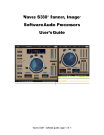
S1
Stereo Imager
Table of Contents
Register Now! ................... see WaveSystem Manual
Chapter 1 ..................... About the S1 Stereo Imager .... 3
Before you start ............ 3
Features and applications ............ 3
S1 component plug-ins ........... 4
Chapter 2 .......................................The S1 Interface .... 5
Stereo Vector Display™ ............ 5
Quick guide screen shot ............ 5
The Controls ............ 6
Gain, Width ............ 6
Asymmetry, Rotation, Shuffling, Frequency ............ 6
LR/MS input, Bass Trim, Reset ............ 7
Signal path (Order of action of controls) ............ 7
Chapter 3 ............................................ Using the S1 .... 8
Graphical control ............ 8
Hints for Use ............ 8
Mastering and general use ............ 9
To mix multiple stereo sources with S1 .......... 10
Mono Compatibility .......... 10
Chapter 4 ........................ About MS and MS modes .. 11
What is MS? .......... 11
How is MS used? .......... 12
Polarity/Channel swap in MS mode .......... 12
Use of LR/MS meter mode .......... 13
Chapter 5 .................................... Other S1 controls .. 14
Peak counters .......... 14
Output clipping (the Gain control) .......... 14
Chapter 6 ....................................... Special MS uses .. 15
Using the S1 MS options .......... 15
MS Equalization .......... 15
Uses of MS equalization .......... 16
How to do:
Overall EQ .......... 16
Frequency-dependent width .......... 16
One-point microphone compensation .......... 17
FM broadcast noise reduction .......... 17
One-sided equalization .......... 17
S1 Plug-in Manual
1
Chapter 7 ...............................More about shuffling .. 19
Chapter 8 ........................ History of stereo controls .. 20
Chapter 9 . What kind of stereo will the S1 work on? .. 21
Chapter 10 ...................................... Key commands .. 22
Chapter 11 .................................. Stereo monitoring .. 23
2
S1 Plug-in Manual
Chapter 1 - About the S1 Stereo Imager
The S1-Stereo Imager combines a number of classical stereo processing techniques with Waves’ intuitive user
interface to provide a powerful and unique ‘stereo toolkit’ for use in mastering and digital editing situations. S1
may be used to correct faults inherent in a stereo recording or mix, or it may be used to creatively enhance the
stereoism of existing stereo material.
S1 is based on recognized engineering principles and does not purport to create a three-dimensional soundfield
from a two-loudspeaker system or to create a pseudostereo master from a mono source. Because S1 is based on
established audio engineering principles, it offers a high level of mono compatibility with minimal side effects.
S1 provides the means to readjust the stereo level-balance of a mix and has the ability to dramatically widen an
existing stereo image, again without introducing significant side effects. For example, an assymetrical mix can be
adjusted so as to re-balance the left and right components without affecting the position of the centre image or,
alternatively, the center image may be panned left or right without affecting the balance of the stereo components
of the mix.
Like all Waves plug-ins, S1 is based around a graphical interface and is designed to be both straightforward and
intuitive to use. You can adjust all parameters via traditional numerical displays or directly from the graph, giving
you the choice of interface and control.
Before you use S1, you should have a good working knowledge of both the host application software and your
computer. If you’ve used a Waves plug-in before, you’ll probably be able to find your way around the S1 interface
with minimal reference to this manual. However, we recommend you read it through at least once just so you
know all the things S1 can do.
Before you start
Please make sure that your monitoring system is in phase and set up symmetrically about your normal listening
position! This may seem obvious, but because S1 is designed to operate on the spatial aspects of a mix, it is
imperative that your monitor system conveys an accurate sense of stereo imaging. If you have any concerns about
your monitoring arrangement, please read the Stereo Monitoring chapter.
Features and applications
Particular care has been taken in the design of S1 to avoid unpleasant and fatiguing ‘phasiness’ effects and to
retain a high level of mono compatibility. Mono sounds remain uncolored; S1 does not change the basic tonal
character of the original sound, but simply sweetens and broadens the spaciousness of the stereo image.
A classic phase-compensated ‘shuffler’ is provided to both enhance the stereo spaciousness and improve the
image quality at the bass end of the audio spectrum, again without introducing phasiness. The amount of
shuffling and the range of frequencies affected are user-controllable so that the effect may be optimized for a
variety of stereo source material.
The S1 Stereo Imager also has the unique capability of rebalancing a stereo mix, and of altering the positions
within the stereo stage of individual parts of a stereo mix. By allowing the user to manipulate the relative balance
S1 Plug-in Manual
3
of the central, left and right stereo components of a mix, it is possible to ‘pan’ the left/right and center components independently. In addition, the relative balance of the left/right and center signal may be also changed to
either narrow or widen the perceived stereo image. S1’s unique and informative stereo vector display allows the
effect on level balance and positioning to be precisely visually monitored while making adjustments.
Stereo level metering is provided in both left/right and M/S modes so that the effect on stereoism can be fully
monitored. As with some other Waves plug-ins, correction is provided for the two most common stereo imaging
errors: channel polarity (‘phase’) errors and stereo channel reversal.
This stereo remix capability makes the S1 suitable not only for sweetening and enhancing adequately mixed
stereo masters, but also for more drastic corrective and creative remix work. Because S1 doesn’t rely on gimmicky
processes to achieve its results, it may be used to make subtle improvements even to refined ‘purist’ stereo
recordings. The S1 does not add any unwanted sound effects not already present in the original recording. Rather
it is designed to enhance and rebalance what is already there.
S1 Component plug-ins
On most host applications and platforms you can select just the audio processing you need, and use only the
power necessary to do the job. The S1 has several plug-in components in the menu. They are all stereo-outputonly plug-ins and can not be used for mono-to-mono processing. On some native platforms, 88.2/96kHz support
is now available.
Here are the current components as of this printing; new ones may be added in future updates, and will be noted
in the plug-in Read Me files. Some examples for each component are listed:
• S1 Shuffler — This is the full plug-in, with all controls, including Width, Rotation, Asymmetry, Shuffling,
plus all channel controls (phase, gain, etc.), and does not count clips; (for mastering, to fix off-center or
unbalanced mixes, precision image adjustment, change wideband width, expand low frequency image, Rotate
true stereo sources without collapsing image, creation of strong antiphase content)
• S1 Shuffler (48) — The full mastering plug-in (TDM only!), same as the S1-Shuffler, but 48-bit double
precision resolution; (applications same as S1 Shuffler but when increased resolution is needed)
• S1 Imager — Omits the Shuffler and Bass trim controls. Ideal for adjust Width, Rotation, and Asymmetry
only; (saves processing power if Shuffling is not needed, excellent for stereo mixing to Rotate stereo-mic or
submixes into place)
• S1 MS — Simply an MS converter (a matrix) that converts left-right input into MS output, (or vice versa).
It has no controls or metering, and is designed so that if the input does not clip, neither will the output.
Due to the nature of the matrix, the gain is reduced by 3dB in this process to avoid clipping. Therefore, if
you use two MS modules in a chain (say for equalization of just the M or S channel), then the total chain
will have a nominal signal drop of 6dB (3dB per MS module, also assuming the EQ is flat with unity gain).
4
S1 Plug-in Manual
Chapter 2 - The S1 Interface
For complete information on basic Waves interface control, read the WaveSystem Manual.
The distinctive interface of the S1 lets you easily see and control the stereo soundstage of a file. The most
noticeable feature of the interface is the stereo vector display, with its half-circle shape and soundstage graphic.
The stereo vector display of the S1.
The stereo vector display does not show anything about the input signal. It shows you:
1 - the output positions of the original left, center, and right sounds;
2 - an accurate indication of their changed levels in dB so you can adjust level-balance between original left,
center, & right sounds.
The stereo vector display does not show the effect of shuffling, but only gain, width, asymmetry, & rotation.
Shuffling is a process applied after these processes.
The S1 control interface.
S1 Plug-in Manual
5
The Controls
Gain - simply controls overall gain level without altering stereoism. Gain is displayed in dB.
Width - This alters the width of the input stereo signal. For width values less than 1, the sound stage is narrowed,
becoming mono for width zero. For widths greater than 1, the sound stage is widened, with sounds at the two
edges of the stereo stage being moved beyond the loudspeakers. The stereo is unchanged when Width equals 1.
Start around 1.2 for moderate enhancement, plus a little Shuffling.
Asymmetry - This acts after initial width adjustment. This unique control does not affect central mono in-phase
sounds in any way, but adjusts the relative level of left and right sounds. It differs from conventional balance
control in that it keeps center sounds in the center. This control is particularly useful for altering the relative levels
at the two sides of the stereo stage without moving a mix off-center, or biased in position to one side or the other.
Rotation control - This control allows adjustment of the centering of the entire stereo image without any effect
on relative sound levels in different parts of the stereo stage. It is particularly useful for centering a stereo mix
biased to one side of the stereo stage without altering the mix level balance, and for mixing stereo-miked sources,
serving as a true stereo 'pan' control.
Useful tip: No separate stereo balance control is provided, but if you drag both the Asymmetry and Rotation controls
together, then their combined effect is that of a balance control. For most platforms, they may be dragged together by
dragging in the space between the two controls, or by selecting both controls first then dragging on one.
6
S1 Plug-in Manual
Shuffling - This increases stereo width at bass frequencies to help compensate for the fact that the ears hear stereo
effects as being more narrow in the bass than in the treble. Subjectively, it has the effect of making stereo images
more spacious. Unlike previous commercially available stereo shufflers, it is fully phase compensated, i.e. does not
introduce unwanted phase errors between the stereo channels. This gives improved stereo sound quality with low
listening fatigue. It is also carefully designed to minimize tonal alterations of the mix in the bass. It comprises two
controls: shuffling and frequency. Shuffling controls the magnitude of bass width increase between 1 (no
shuffling) and 3 (maximum bass width increase). The subjectively best value usually lies between 1.6 and 2.5.
Frequency - controls the frequency below which the Shuffling effect is increased. This frequency may be adjusted
between 350 and 1400 Hz. For normal stereo monitoring, a frequency between 600 and 700 Hz usually sounds
best, although a higher frequency may be better if used with the very close loudspeakers often used in multimedia, portable, or TV one-piece reproducer systems where the stereo speakers are in the same box. A lower
frequency is useful when adjusting stereo originating in stereo microphone techniques where the microphones
are spaced apart by perhaps 20 or 30 centimeters.
LR/MS input button - Changes input mode to accept either standard Left-Right inputs or Mid/Side (MS) inputs.
See the chapter About MS.
Bass Trim - Adjusts the level of bass when the Shuffler is in use. When set to 0, bass level stays more or less the
same. On some material, higher Shuffler settings may need bass trim of 1 or 2 dB boost to compensate for any
subjective shift in bass level.
Reset - This button restores Width, Asymmetry, Rotation and Shuffling to settings at which they have no effect
on input stereo. Hint: By repeatedly using the Undo button after using Reset, you may do A/B comparisons between
unprocessed and processed stereo effects, without altering gain or channel polarity and swap settings.
Signal path (Order of action of controls)
The controls act in the following order between input and output.
LR/MS input button to set input mode;
then Channel polarity to correct possible stereo phase errors on the input signal;
then channel swap to correct possible stereo reversal on the input signal,
then Width,
Asymmetry,
Rotation,
Shuffling/frequency,
and finally Gain.
S1 Plug-in Manual
7
Chapter 3 - Using the S1
• First, preview or audition the stereo audio source you wish to process.
• Experiment with each control to learn the effects of each. It is best to return each control back to the default
position before adjusting the next one! Refer to the section The Controls for detailed explanations of each.
• Due to the processing used in the S1 to modify the soundstage, you may sometimes need to reduce the gain
level of any high-level files by 3 dB or more to avoid output clipping. For more information, see the Output
Clipping section.
Graphical control
A unique and flexible feature of S1 is the ability to control the processing from the graph.
To control the S1 from the graph:
(For ease of explanation, the following instructions assume that you have clicked the Reset.)
• Click and drag on the center line (pointing straight up). This line represents the center channel.
• Drag left/right to change Rotation.
• Drag up/down to change Gain.
• Option-drag left/right to change Width. (PC uses Alt key).
• Option-drag up/down to change Asymmetry.(PC uses Alt key).
• Hint for Mac: you can press and release the option key without re-clicking; this lets you change any of the four
controls listed above in one step.
Hints for Use
Using the S1 will provide subtle or extreme manipulation of the full stereo mix, stereo-miked tracks, reverb
returns, submix groups, and so forth. The Gain, Width, Asymmetry and Rotation controls in combination can
be used for a great variety of different adjustments and remixes of the original stereo source. (And the S1
Rotation will pan dual input mono, so can be used to replace the pan control across the mixing board for all
channels, whether mono or stereo).
Adjustment of Gain and Rotation
8
S1 Plug-in Manual
Mastering
Quick tip: Use the "one-click" adjustment of an input stereo image by using direct graphic control, described on
the first page of this chapter. You can hold and release the option(Alt) key while dragging without having to let
up on the mouse to easily adjust all four controls; Gain/Rotation, or Width/Asymmetry.
To adjust stereo positioning without any effect on the internal level-balance of a mix, use the Gain and Rotation
controls only (and the channel swap button if reversal of the i
Adjustment of Width and Asymmetry to modify level balance.
Left, Center at 0 dB gain, Right at - 4 dB gain.
Conversely, to adjust the internal level-balance of a mix without any effect on the stereo positioning of central
images, use the Width and Asymmetry controls only. This adjustment may be done by depressing the option
(Alt) key and dragging the mouse from the vector display screen.
If the effect of a level-balance adjustment using Width and Asymmetry control is that the stereo image is too
narrow, you may find that increasing the amount of Shuffling will help to restore width without much effect on
perceived level balance.
Dragging Rotation and Asymmetry control together acts simply as a conventional balance control, albeit one
acting after the Width control. (You can conceptually think of the Asymmetry control as being a balance control
with a rotation to restore the center sound to center position.)
It is worth noting that the Rotation control has NO EFFECT on the internal sound balances of stereo mixes, only
on their positioning.
Besides making the sound stage wider or narrower, Width does have an effect on level balance, making non-central
sounds louder relative to central sounds as the width is made larger. This can sometimes be useful for changing the
relative balance of central and edge sounds. But
beware: this only works in stereo, and does not change the balance heard by a mono listener, e.g. via a mono radio or TV.
Asymmetry changes relative balance of left & right both in stereo and in mono.
S1 Plug-in Manual
9
To mix multiple stereo sources using S1
Using faders with pan controls to mix several stereo submixes, or stereo-miked or other stereo sources can cause
images to be narrowed or collapsed. This is unnecessary and awkward to adjust.
By simply using the Rotation control in the S1 plug-ins, a complete stereo input can be rotated into place. It's
very similar to turning your head to listen off-angle, instead of using the pan controls, which has the side effect of
reducing the stereo image. (This is done by panning the L and R unequally, such as L all the way to left and R
being panned straight to center, 'squeezing' a sound halfway to the left.)
Insert the S1-Imager or S1-Shuffler onto each of your stereo submixes or sources you want to mix to a final
output pair. Any mono instruments can be input too, and they will simply be panned, if input to both L and R of
the S1 plug-in. Width and Shuffling have no effect on dual mono.
Mono Compatibility
When stereo sound is broadcast via radio or TV, a significant proportion of listeners will be listening to mono. In
that application, it is important that stereo mixes also be mono-compatible, i.e. that no sound in the mix
becomes colored, disappears, or becomes excessively quiet..
The S1-Stereo Imager is designed such that, with material mixed on standard stereo equipment, the processing
does not cause coloration in mono listening.
The mono compatibility of reprocessed stereo material can be judged using the stereo vector display. The closer
the “vector” or lines corresponding to left, center and right inputs are to being vertical on the display, the more
mono-compatible is the mix, whereas the closer they are to being horizontal, the quieter will be that sound
position in the mono mix. In practice, mono compatibility will usually be good if all three lines are within 45
degrees of being vertical, and adequate if all three lines are within 60 degrees of being vertical.
If mono compatibility is particularly important to you, you are advised to monitor the mix via a mono reduction
of the mix as well as in stereo. Many mixing desks or monitoring systems have a “mono” monitoring button.
10
S1 Plug-in Manual
Chapter 4 - About MS and MS modes
What is MS?
f
In addition to conventional left-right input mode, the S1 also offers processing in what is known as MS stereo
mode, also termed sum-and-difference mode.
MS mode is an alternative way of handling stereo signals that has many advantages and unique possibilities for
stereo processing. Although MS mode has been used since the very start of stereo in the 1930s, it has only gained
widespread use over the last decade, often being used in stereo TV production. But it's also used for various
stereo microphone techniques and in other audio-only applications.
Briefly, M and S signals are derived from left and right by a matrix process. M stands for "mid" and S for "side"
signals. The signal produced by an "MS" microphone is in this format and needs conversion from the MS to
standard LR. However, the S1 offers unique processing of the signal before it is converted, and also allows any LR
signal to be converted into MS for the same processing. In the Special MS uses chapter, examples of MS processing are explained.
The mid signal M, also termed mono, is simply obtained by taking the average of the left and right channels.
Mathematically:
M = (1/2)(L+R)
where L is the left waveform magnitude and R is the right waveform magnitude.
The side signal S is obtained by subtracting the right signal from the left with the same overall gain as used for
the M signal. Mathematically:
S = (1/2)(L-R).
The process used to derive the M and S signals from L and R is known as an MS matrix.
The MS matrix process may be applied again to the M and S signals to recover the original left and right,
although an additional gain of 2 (+6 dB) is needed to get the original gain. Mathematically
L = M+S and R = M-S.
i.e. Left is the sum of the M and S signals and Right is the difference of the M and S signals.
How is MS used?
MS signals have various properties that make them useful for stereo processing. The M signal is simply the mono
signal heard when a stereo signal is listened to on mono equipment. The S signal is zero when the left and right
channel sound is identical as it is for sounds panned exactly to the middle of the stereo stage. This is why S is
called the "side" signal —it only contains that part of the sound positioned to either side of the center position.
S1 Plug-in Manual
11
The standard S1 Shuffler or Imager can be used with input stereo signals from either standard left-right (LR)
stereo or MS stereo. In both cases, the output is in standard left-right stereo mode. Click the button above the
channel swap/polarity buttons to select which mode you need. In MS mode, what is normally the left input
channel now accepts the M signal and what is normally the right input channel now accepts the S signal.
M and S outputs from an MS stereo microphone may be fed into the S1 using MS input mode, and the output
will be in conventional left-right mode with the gain, width, asymmetry, rotation and shuffling controls affecting
the sound in the usual way. MS signals may also be available from other equipment, such as stereo tracks
recorded in MS mode on a video tape recorder.
Polarity/Channel Swap in MS mode
The polarity and channel swap buttons in the input to the S1 are intended to compensate for errors in the input
signals. However, they work somewhat differently when the S1 is in MS Input mode! The polarity buttons alter
the polarity of the incoming M or S signals as shown on the screen, and the channel swap button now interchanges the M and the S input signals.
The perceived effect of polarity and swap on the output stereo when the input is in MS mode is as follows:
Using only one of the polarity buttons in MS input mode has the effect of reversing the stereo image, swapping
the left and right signal fed to the subsequent stages of S1 processing.
Using the channel swap button in MS input mode has the effect of leaving the left and right inputs to the S1
unaltered except that the polarity of one of them is inverted.
These effects arise from the mathematics of MS matrixing.
Therefore, be aware that if you wish to swap the left and right input while in MS input mode, you would activate
the M polarity button, and not the channel swap button (as in illustration below).
12
S1 Plug-in Manual
Use of MS meter mode
The S1 meters have two modes of display: LR and MS. The LR mode is standard Left and Right indication. MS
mode is explained below.
To switch between LR and MS modes, click the L-R (or M-S button) above the meters. Switching the meter mode
does not affect the audio output in any way.
MS meter mode shows the levels of the stereo “mid” and “side” signals M and S, i.e. the respective average of the
two channels and the difference between the channels. The M signal contains most of the “mono” information in
the stereo signal, and the S signal contains most of the stereo. Monitoring their levels give useful data about the
stereo signal — the more level there is in S relative to M, the more stereo information there is.
The MS meter mode can be used to judge whether the input stereo material is in phase. If it is, the M level will
generally be significantly higher than the S.
If the S level is generally higher than the M level, this indicates one of two possibilities:
(a) the most likely possibility, that the input channels are out of phase. For example, an analog-domain wiring
error in balanced cables somewhere in the stereo signal chain, an incorrect setting of a phase switch, or possibly
an incorrectly wired microphone capsule in a stereo pair of microphones. Correct this by altering one only of the
two input polarity buttons to read “ - “ rather than “ + “. Listen via loudspeakers to verify that this does indeed
improve the sharpness of stereo images, particularly for sounds at the center of the stereo stage.
(b) in unusual cases (e.g. certain specialist one-point stereo microphone recording techniques such as MS or
“Blumlein figure-of-eight” when presented with a very wide sound source stage, or if previous excessive width
adjustment has been used) it is possible that the S meter can read higher than the M without a channel polarity
error dues to excessive width. In this case, center stage sounds WILL be in phase, and channel phase adjustments
should NOT be made.
This case is an unusual one - you may never encounter it. It can be distinguished from the case when the stereo
channels are out of phase by one or both of the following listening tests. (A) narrow the width on the S1. Do
center stage sounds become more solid and the sound become more natural? If so, then the original width was
excessive. If, on the other hand, the center sounds become very quiet, the channels were out of phase. (B) If the
rotation control is adjusted to the left, do center sounds also move over to the left? If so, then the channel polarity
is correct. If the center sounds move over to the right, then the channel polarity is wrong.
If the M and S levels are roughly the same without processing, the two channels are largely uncorrelated and no
judgement can be made from the meters about correct channel phasing. In this case, if there are no center stage
sounds but the channels are entirely independent sounds, then no polarity adjustment is required. If there are
center sounds, listening tests A or B above should be used to adjust channel polarity correctly.
When processing is applied to correctly phased input stereo material, it can be useful to monitor the results on
the MS meters. In cases where an ambient effect is provided, it is often useful to adjust width and/or shuffling so
that the S meter levels are comparable to or only a little less than the M meter levels. If the S meter levels are
typically larger than the M meter levels, then the degree of width or shuffling or, just possibly, rotation is likely to
be excessive, and should generally be reduced.
S1 Plug-in Manual
13
Chapter 5 - Other S1 controls
Some controls in the S1 are different or exclusive from those described in the WaveSystem Manual. These
exceptions are covered in this chapter for convenience.
Clip meters and Level indicators
The peak and clipping indicators only give correct indications in L/R mode, where they show peak levels and any
clips independently in the left and right channels. Do not rely on peak and clipping indications in the M/S mode.
Whenever switching back to L/R mode, please reset the peak and clip indications to obtain an accurate reading.
Output Clipping (the Gain control)
The S1 can cause clipping of high-level files, even at default settings.
The unique phase compensation feature of the S1 assures low subjective “phasiness” of the stereo image. This
uses phase manipulations to modify and improve stereo quality. However, even at the unity-gain default or reset
settings of no shuffling or width alterations, these phase manipulations have a side-effect of altering the levels of
peaks in the audio signal, so that on normalized or peak limited sound files, you may sometimes need to reduce
the gain level by maybe 2 or 3 dB to avoid output clipping. Set the S1 gain so that no clipping registers on the
output level meter in L and R mode.
For this reason, to get maximum output level, it is very strongly recommended to do normalization of level or
peak limiting using the Waves L1 peak limiter AFTER processing by the S1 rather than beforehand.
Here is an example of how to use the S1 and L1 together for stereo image adjustment while maintaining unity
gain.
Insert the S1-Shuffler first, followed by the L1 limiter or +L1. (This example is for systems that support multiple
real-time processes, whether DSP or Native-based).
Assuming you have high-level files, or wish to be sure to avoid any clipping, first set the S1 gain to -6.0dB.
Next, set the L1 Threshold to -6.3dB, and the Out Ceil to -0.3dB. By using the L1 merely as a limiter to control
any new peaks created by the S1 process, unity gain is maintained while giving 'safe' adjustment headroom for
the S1 processes. Of course, additional gain beyond unity can be achieved with limiting, by lowering the L1
Threshold even further.
14
S1 Plug-in Manual
Chapter 6 - Special MS uses
Using the S1 MS options
f
The "Mastering" plug-in S1-Shuffler (48) <for TDM only> is preferred for high resolution mastering and
critical applications. Its incorporation double-precision resolution ensures the highest possible quality in matrix
operations and MS adjustments.
The smaller S1 component plug-ins are the preferred options where several Waves processors are cascaded one
after the other or otherwise used together, because they then use up as little of the DSP power as possible,
allowing more of other Waves component plug-ins to be used within the DSP limits of the user's system. They
are ideal for MS use.
The power of the MS functions of S1 is greater when used with other Waves components, notably the Q10 (or
Renaissance) equalizer, and various examples of use are described in the following sections.
MS Equalization
The small modules of the S1, along with those of the Q10, allow a kind of EQ that is different from conventional
equalization of left and right stereo channels. It is known as MS equalization. This kind of EQ can achieve unique
effects on stereo signals that cannot be obtained any other way, altering not only the overall tonal quality, but also
the spatial effect of a stereo recording.
MS equalization is obtained by the following cascade of processors
MS Matrix
Q(n) Equalizer
S1 Shuffler
or S1 Imager
or +S1 Shuffler
using an MS matrix followed by an "n-band" stereo EQ component from the Q10 (n= up to 10 bands of EQ),
followed by an S1 module having the desired output facilities. If the output of the MS equalizer is to be fed to
other processes in TDM or in 24 bits, the S1 Imager or S1 Shuffler modules may be used depending on whether
shuffling is desired or not. One other option is to use another MS plug-in at the end instead of the Shuffler or
Imager, but only if you don't want to use Width and other options in those components.
Setting up the MS EQ chain
When using any of these chains, first set the final S1 plug-in to MS input mode, and ensure that the polarities are
both "+" and that channel swap is not activated. Reset the output S1 module to avoid any other S1 processing at
first. In the Q(n) equalizer, set the polarity buttons to "+" and make sure the channel swap button (if present) is
not activated.
S1 Plug-in Manual
15
The effect of this processing chain is that what is normally the left channel of the Qn equalizer now equalizes the
M signal and what is normally the right channel of the Qn equalizer now equalizes the S signal.
By giving the M and S channel signals different gains at different frequencies, you can vary the width of the stereo
in a frequency-dependent way. For instance, if you boost the S channel at 1kHz, then the output will have greater
stereo width around 1kHz. If you boost the M channel at 1kHz, then the output will have a decreased width (and
stronger 'phantom' channel) around 1kHz. A practical example would be to increase the midrange of Crown
SASS microphone outputs, which many times have a 'hole-in-the-middle' effect on some sources; a reasonable
boost around 400Hz of the M channel makes a significant difference without affecting the general stereo imaging
in other frequencies.
You are now ready to start using the processing. Here are a few of the possible applications.
Uses of MS equalization
Overall EQ
Open the Q10 (or Renaissance EQ) interface. Ensure that the stereo channels are set to "Strap" or "Link". Then
adjust the EQ in the conventional way to equalize both channels.
Frequency-dependent width
This is a new range of adjustments. Open the EQ interface. The procedure to adjust the width as a function of
frequency involves the following steps.
[1] Start with identical EQ settings in both the M and S channels. Make sure the eq is in "Strap" mode.
[2] Select in a given band the type of filter you want, its frequency and Q, and any overall gain adjustment in
that band that you wish. Then "unstrap" the EQ and click the Right button so that you can change just that
side, which is the S channel.
[3] In that band now adjust the degree of boost and cut required to alter width in that band. Increase of gain
will increase width and decrease of gain will decrease width, but only of that band's frequencies.
[4] In general, this adjustment will have altered tonal quality. To restore tonal quality, select "strap" and then
adjust the gain in that band up and down until the tonal quality is what you want again. By adjusting both
bands while strapped together, the new width adjustment is maintained (as a difference in gain between the
two channels).
[5] If further adjustment is required, return to step 2.
It is important that you make these adjustment with strap on or off as indicated in each step. Otherwise the
adjustments in the stereo sum and difference channels will no longer track together.
Please note it is preferable to do overall bass shuffling using the final S1 Shuffler rather than adjustments on the
EQ, since the former is a design dedicated for the job.
16
S1 Plug-in Manual
Overall (wideband) width is also preferably altered on the output S1 plug-in, using the Width control. Altering
the gain of the M and S channels of the Qn separately will also alter width, with an increase in S gain increasing
width and a decrease decreasing width. But to avoid confusion, it is preferable to use the Qn gains only for overall
gain adjustment and to avoid clipping in the Qn by altering both channel gains together.
One-point microphone compensation
For example, most stereo one-point microphones suffer from reduced width in bass due to low-frequency rolloffs in the directional microphone component characteristics. This may be compensated by boosting the S
channel on the Qn at 6dB per octave by using a low shelf set to +18 dB and sliding it in frequency to compensate.
Normally, the frequency will be set to below 100 Hz, a figure of 16 to 50 Hz being common for best results.
Similarly, dummy head recordings or spaced identical microphones pointing in the same direction (typical
spacing 15 to 50 cm) can be "Blumlein shuffled" by the same technique but using a higher boost frequency, say +
3dB at 300 Hz on the S channel, along with say a -1 dB shelf on the M channel to compensate to the resultant
exaggerated bass. The channels may then be relinked and the frequency slid up and down to adjust width or
adjust for different microphone spacings.
FM broadcast noise reduction
FM broadcast reception typically has more noise in the S channel than the M channel. Material affected by Schannel hiss can be filtered in the S channel with a tunable notch filter to reduce noise, while having no effect on
the tonal quality of center stage sounds, which are in the M channel.
One-sided Equalization
The small S1 modules with small Q10 modules can also be used for a unique mode of EQ termed one-sided EQ
which allows the EQ on one side of the stereo stage to be adjusted without affecting the EQ of sounds in the
middle of the stereo stage. For example, you can make sounds on the left have a brighter treble without affecting
the sound of center-stage vocals. This can be very useful in remastering stereo mixes or submixes, as one has
much finer control over the EQ effect in different parts of the stereo stage.
The basic process uses three small modules in cacade:
S1 Imager
Q(n) Equalizer
S1 Imager
although the last stage can also be an S1 Shuffler or +S1 Shuffler if desired.
S1 Plug-in Manual
17
If one wishes to EQ the left side sound without EQ'ing the center, the first S1 Imager is loaded with the setup file
"S1 LeftSideIn" and the second S1 Imager is loaded with the setup file "S1 LeftSideOut"
If one wishes to EQ the right side sound without EQ'ing the center, the first S1 Imager is loaded with the setup
file "S1 RightSideIn" and the second S1 Imager is loaded with the setup file "S1 RightSideOut"
The input and output S1 imager files are designed such that if the Qn is set to flat, then apart from an overall gain
change, there is no effect on the stereo. If the channels of the Qn are strapped and the EQ's varied together, this
adjusts overall EQ in the usual way.
What is new here is what happens if one unstraps the two channels of the Qn. When using the LeftSide setups,
adjusting the EQ of the left channel of the Qn adjusts the EQ of the left-side sounds of the input stereo signal, but
has no effect at all on sound at center stage, which remain unequalized and stay at the center position!
When using the RightSide setups, adjusting the EQ of the right channel of the Qn adjusts the EQ of the right-side
sounds of the input stereo signal, but has no effect at all on sound at center stage, which remain unequalized and
stay at the center position! Excellent when needed.
18
S1 Plug-in Manual
Chapter 7 - More about shuffling
Shuffling is a stereo enhancement process that has few unwanted side effects, but which can add a sense of
spaciousness and life to an otherwise ordinary stereo effect.
Shuffling is particularly suited to recordings made using standard stereo panning techniques made on most
stereo mixing consoles or their digital equivalents.
The stereo effect from two loudspeakers creates the illusion in the ears and mind of the listener of illusory
phantom images lying between the loudspeakers. This illusion, however, is not perfect, and one known fault is
that for sounds panned to intermediate stereo positions, the apparent stereo stage width is narrower at bass
frequencies than in the mid and high treble. This is known to be connected with the fact that the ears and brain
determine sound direction by different methods below and above around 700 Hz.
Shuffling is a process that widens the bass frequencies so as to make the phantom bass and treble images seem to
be of comparable stage width. This generally occurs when the shuffling level is set at around 1.6 and shuffle
frequency around 650 Hz. This setting is recommended for sharpest stereo imaging.
If you increase the bass width even further, so that the bass is over-wide compared to the treble, it will create less
precise stereo images, but generally tends to create an illusion of “spaciousness” and sounds from beyond the two
stereo loudspeakers. This helps makes up for the fact that the stereo image is normally confined to the space
between the loudspeakers, rather than being all around as in real life. This effect is generally best when the
shuffling level is between 2.0 and 2.5, and shuffle frequency around 650 Hz. This setting is recommended for best
spaciousness on most material.
Such settings are especially useful on stereo material that otherwise sounds too narrow.
Shuffling has no effect on the stereo imaging of central or mono images, but only on sounds panned away from
the center. Its effect is not to enhance mono images, but rather to enhance the stereo effect already present in
stereo images.
Unlike previous commercially available stereo shufflers, it is fully phase compensated, i.e. does not introduce
unwanted phase errors between the stereo channels. This gives improved stereo sound quality with low listening
fatigue. It is also carefully designed to minimize tonal alterations of the mix in the bass. The application of
shuffling has no significant effect on mono compatibility.
It comprises two controls: “shuffling” and “frequency”.
“Shuffling” controls the magnitude of bass width increase between 1 (no shuffling) and 3 (maximum bass width
increase). The subjectively best value usually lies between 1.6 and 2.5.
“Frequency” controls the frequency below which the shuffling width is increased. This frequency may be adjusted
between 350 and 1400 Hz. For normal stereo monitoring, a frequency between 600 and 700 Hz usually sounds
best. A higher frequency may be better if the sound is intended to be used with the very close loudspeakers often
used in multimedia or portable or TV one-piece reproducer systems where the stereo speakers are in the same
box. A lower frequency is useful when adjusting stereo originating in stereo microphone techniques where the
microphones are spaced apart by perhaps 20 or 30 centimeters.
S1 Plug-in Manual
19
Chapter 8 - History of stereo controls
Width control was invented in 1931 by Alan Blumlein. It is probably the oldest control for adjusting stereoism,
pre-dating even the balance control. It has been included in many stereo mixing desks, and even a few hi-fi
amplifiers, since then. However, despite its usefulness, it still has not come into universal use.
Asymmetry control: this is the first commercial product using this control, which was devised by Michael Gerzon
in the mid 1980’s.
Rotation control: Although a stereo rotation control was available in the 1950’s from at least one central European manufacturer, Telefunken, it never came into general use and has been forgotten except in German
broadcast mixing desks. An Ambisonic version of this control has been available in Soundfield microphone
control units manufactured by Calrec, AMS, Drawmer and AGM since the late 1970’s.
Shuffling. The terms “shuffler” and “shuffling” were coined by Blumlein in the 1930s. This particular kind of
shuffling was devised at EMI in England by Vanderlyn in the 1950s, and used for a brief period by EMI in their
early “Stereosonic” recordings, but fell out of use, largely because at that time EMI used recording techniques for
which it was not especially effective. Individual recording engineers, including Tony Faulkner in England,
devising their own equipment since then have used shuffling, and it was rediscovered by David Griesinger at
Lexicon in the mid 1980’s and incorporated as an effects program in various of their digital effects units.
Although the importance of phase compensation was known to Vanderlyn in the 1950’s, and was incorporated
into EMI’s own equipment of the period, the S1 is believed to be the first commercially available shuffler to
incorporate phase compensation.
Further reading on stereo
Probably the best generally available source of information on the enormous amount known about the stereo
effect can be found in:
“Stereophonic Techniques”, edited by John Eargle. An anthology of reprinted articles on stereophonic techniques,
Audio Engineering Society, New York, 1986. Obtainable from the Audio Engineering Society. This anthology
contains many of the classic articles and research papers on the stereo effect from 1931 to 1985.
20
S1 Plug-in Manual
Chapter 9 - What kind of stereo will the S1 work on?
The S1 will give excellent results for adjusting the stereo effect of most kinds of standard stereo material produced
in the recording studio and on conventional stereo mixing desks or their digital equivalents.
For such stereo, the only precaution needed is to ensure that the two channels are in phase. Accidental polarity
reversal between the stereo channels can sometimes occur due to miswired leads or connectors in the analog
domain. If stereo channels are out of phase, the S1 will not work correctly until the phase is corrected by the
polarity buttons (see the section phase reversal and channel swap earlier in this manual). You may notice a
polarity reversal because central stereo images are “unsharp” and bass-light in sound, or by the fact that when the
output meters are in M/S mode, the level on the difference S channel is consistently larger than the M output
level. With such out-of-phase stereo, you will find that center-stage sounds move in the wrong direction as you
apply the rotation control. To correct this problem, click on one of the polarity buttons so that it reads “-” while
the other remain at “+”.
However, for some stereo microphone techniques used for live recording, the S1 may not always work in quite
the way expected. The basic advice here is simply to use your ears in judging the S1’s effect when used with such
recordings. The S1 will usually work very well with recordings made with “one-point” stereo microphones in a
single small housing, sound field microphones and with MS stereo microphones.
However, when the microphones in a stereo pair are spaced apart by more than a few centimeters, sounds that
are not exactly center-stage will arrive at different times at the 2 microphones, and in different phases. These time
and phase difference will affect the operation of the S1.
When used with stereo microphone systems where the mics are spaced apart by more than a few centimeters but
less than about 1 meter, you may find that the width control does not always work well on the “phantom” sound
images between the loudspeakers, and can sometimes gives such images a colored and more out-of-focus sound.
In such cases, leaving the width near a value of 1 and using only the gain, asymmetry and rotation controls may
work best. You may also find it helpful to use a lower value of shuffler frequency than normal in such cases.
With stereo recordings using very widely spaced microphones (say more than 1 meter apart) as the stereo pair,
you may find that rotation or asymmetry control used on their own are not effective, but that dragging them
together, so that they act as a balance control, may be effective. In this case, width adjustment may again sometimes prove effective.
The S1 may not prove very effective on recordings made with a “binaural” dummy head, or similar approaches to
recording such as the Schoeps “sphere” microphone or the Crown SASS system. These systems produce a very
non-standard kind of stereo, and may not be improved by the S1. These systems ideally require the use of a
different kind of shuffler to that incorporated into the S1 (further details on this may be found in M.A. Gerzon,
“Applications of Blumlein Shuffling to Stereo Microphone Techniques”, J. Audio Eng. Soc., vol. 42 no. 6 pp. 435453 (June 1994).). Width control may not be effective for such stereo microphones. However, although the S1
was NOT designed for use with the stereo produced by such microphone, if you like an effect it produces on
them, feel free to use it.
S1 Plug-in Manual
21
Chapter 10 - Key commands
In the Stereo Vector Display:
• (no key)
• option-drag
to control Rotation (X-axis)
and to control Gain (Y-axis).
to control Asymmetry (X-axis)
and control Width (Y-Axis). (PC uses Alt key).
• For complete information on interface controls, read the WaveSystem Manual. (PCs use the Alt key instead
of Option, for example).
22
S1 Plug-in Manual
Chapter 11 - Stereo monitoring
To monitor stereo effects correctly, it is important to make sure that your stereo monitoring is set up correctly - in
particular that the stereo monitor speakers are matched and are in phase, and that the left and right channels are
the correct way round!
A “left/right” sound file, or the channel identification track on a test CD, can be used for getting them the right way
round. Any speech or music mono sound file, especially those with a lot of bass, can be used to get the speaker polarities
correct — the image will be much sharper and with more bass if the speaker polarities are correct.
If stereo phase is wrong, you may correct it by reversing the “+” and “–” wires from the stereo power amplifier to
the loudspeaker ON ONE STEREO CHANNEL ONLY.
If your stereo amplification system is fed via balanced cables and your speakers are out of phase, it may be that
one of these cables is not wired correctly, causing a monitoring stereo phase error. If so, the connecting wire
should be replaced or rewired to ensure the same polarity.
If the loudspeaker is bi-amplified, i.e. different amplifiers are used for different frequency ranges, it is important
that ALL the amplifiers on that channel are used in the same polarity. If in doubt about this, consult the manufacturer of the bi-amplified loudspeaker or a specialist dealer for expert advice on this.
The best stereo monitoring will be obtained if the loudspeakers are set up symmetrically towards the left and
right, with the listener placed symmetrically so that he or she is equally distant from them. Normally, stereo
monitoring is optimal if the angle subtended by the two loudspeakers at the listener is around 45 to 60 degrees,
i.e. if the distance between the loudspeakers is between 0.7 and 1 times the distance of the listener from each of
the loudspeakers.
The subjective stereo effect heard via headphones will generally not be the same as via loudspeakers. If it is
important to know the effect heard on both loudspeakers and on headphones, both should be used to check a
stereo mix effect. One cannot with certainty predict the effect for headphone listeners by loudspeaker monitoring
or vice-versa. In general, reverbs, and other uncorrelated materials will sound louder in headphones, sometimes
by 6dB or so.
S1 Plug-in Manual
23