1
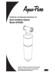
FR-F700P
INVERTER
FR-F700P
INSTRUCTION MANUAL (BASIC)
FR-F720P-0.75K to 110K
FR-F740P-0.75K to 560K
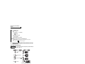
Thank you for choosing this Mitsubishi Inverter.
This Instruction Manual (Basic) is intended for users who "just want to run the inverter".
INVERTER
1
OUTLINE ........................................................................................................1
2
INSTALLATION AND WIRING ......................................................................3
3
DRIVING THE IPM MOTOR <IPM> .............................................................41
4
DRIVING THE MOTOR ................................................................................46
5
ADJUSTMENT .............................................................................................71
6
TROUBLESHOOTING ...............................................................................116
7
PRECAUTIONS FOR MAINTENANCE AND INSPECTION......................141
8
SPECIFICATIONS......................................................................................150
700P
1
2
3
4
5
For the customers intending to use IPM motors ......... 41
This inverter is set for a general-purpose motor in the initial settings.
For use with an IPM motor, refer to page 41.
IB(NA)-0600411ENG-B(1105)MEE Printed in Japan
MODEL
FR-F700P
INSTRUCTION MANUAL (BASIC)
MODEL
CODE
1A2-P39
Specifications subject to change without notice.
INSTRUCTION MANUAL (BASIC)
HEAD OFFICE: TOKYO BUILDING 2-7-3, MARUNOUCHI, CHIYODA-KU, TOKYO 100-8310, JAPAN
B
6
To obtain the Instruction Manual (Applied)
If you are going to utilize functions and performance, refer to the Instruction
Manual (Applied) [IB-0600412ENG].
The Instruction Manual (Applied) is separately available from where you
purchased the inverter or your Mitsubishi sales representative.
The PDF version of this manual is also available for download at "MELFANS
Web," the Mitsubishi Electric FA network service on the world wide web (URL:
http://www.MitsubishiElectric.co.jp/melfansweb)
7
8
This Instruction Manual (Basic) provides handling information and precautions for use of the equipment.
Please forward this Instruction Manual (Basic) to the end user.
WARNING
Incorrect handling may cause hazardous
conditions, resulting in death or severe injury.
CAUTION
Incorrect handling may cause hazardous
conditions, resulting in medium or slight
injury, or may cause only material damage.
CAUTION level may even lead to a serious consequence
The
according to conditions. Both instruction levels must be followed
because these are important to personal safety.
1.Electric Shock Prevention
WARNING
• While power is ON or when the inverter is running, do not open
the front cover. Otherwise you may get an electric shock.
• Do not run the inverter with the front cover or wiring cover removed.
Otherwise you may access the exposed high-voltage terminals or
the charging part of the circuitry and get an electric shock.
• Even if power is OFF, do not remove the front cover except for
wiring or periodic inspection. You may accidentally touch the
charged inverter circuits and get an electric shock.
• Before wiring, inspection or switching EMC filter ON/OFF
connector, power must be switched OFF. To confirm that, LED
indication of the operation panel must be checked. (It must be
OFF.) Any person who is involved in wiring, inspection or
switching EMC filter ON/OFF connector shall wait for at least 10
minutes after the power supply has been switched OFF and
check that there are no residual voltage using a tester or the like.
The capacitor is charged with high voltage for some time after
power OFF, and it is dangerous.
• This inverter must be earthed (grounded). Earthing (grounding)
must conform to the requirements of national and local safety
regulations and electrical code (NEC section 250, IEC 536 class
1 and other applicable standards). A neutral-point earthed
(grounded) power supply for 400V class inverter in compliance
with EN standard must be used.
• Any person who is involved in wiring or inspection of this
equipment shall be fully competent to do the work.
• The inverter must be installed before wiring. Otherwise you may
get an electric shock or be injured.
• Setting dial and key operations must be performed with dry
hands to prevent an electric shock. Otherwise you may get an
electric shock.
• Do not subject the cables to scratches, excessive stress, heavy
loads or pinching. Otherwise you may get an electric shock.
• Do not replace the cooling fan while power is ON. It is
dangerous to replace the cooling fan while power is ON.
• Do not touch the printed circuit board or handle the cables with
wet hands. Otherwise you may get an electric shock.
• When measuring the main circuit capacitor capacity (Pr. 259 Main
circuit capacitor life measuring = "1"), the DC voltage is applied to
the motor for 1s at powering OFF. Never touch the motor terminal,
etc. right after powering OFF to prevent an electric shock.
• IPM motor is a synchronous motor with high-performance
magnets embedded in the rotor. Motor terminals hold highvoltage while the motor is running even after the inverter power
is turned OFF. Before wiring or inspection, the motor must be
confirmed to be stopped. When the motor is driven by the load in
applications such as fan and blower, a low-voltage manual
contactor must be connected at the inverter's output side, and
wiring and inspection must be performed while the contactor is
open. Otherwise you may get an electric shock.
2. Fire Prevention
CAUTION
• Inverter must be installed on a nonflammable wall without holes
(so that nobody touches the inverter heatsink on the rear side,
etc.). Mounting it to or near flammable material can cause a fire.
• If the inverter has become faulty, the inverter power must be
switched OFF. A continuous flow of large current could cause a
fire.
• Do not connect a resistor directly to the DC terminals P/+ and N/
-. Doing so could cause a fire.
3. Injury Prevention
CAUTION
• The voltage applied to each terminal must be the ones specified
in the Instruction Manual. Otherwise burst, damage, etc. may
occur.
• The cables must be connected to the correct terminals.
Otherwise burst, damage, etc. may occur.
• Polarity must be correct. Otherwise burst, damage, etc. may
occur.
• While power is ON or for some time after power-OFF, do not
touch the inverter since the inverter will be extremely hot. Doing
so can cause burns.
4. Additional Instructions
Also the following points must be noted to prevent an accidental failure, injury,
electric shock, etc.
(1) Transportation and installation
CAUTION
• The product must be transported in correct method that
corresponds to the weight. Failure to do so may lead to injuries.
• Do not stack the boxes containing inverters higher than the
number recommended.
• The product must be installed to the position where withstands
the weight of the product according to the information in the
Instruction Manual.
• Do not install or operate the inverter if it is damaged or has parts
missing. This can result in breakdowns.
• When carrying the inverter, do not hold it by the front cover or
setting dial; it may fall off or fail.
• Do not stand or rest heavy objects on the product.
• The inverter mounting orientation must be correct.
• Foreign conductive objects must be prevented from entering the
inverter. That includes screws and metal fragments or other
flammable substance such as oil.
• As the inverter is a precision instrument, do not drop or subject it
to impact.
• The inverter must be used under the following environment:
Otherwise the inverter may be damaged.
Environment
This section is specifically about safety matters
Do not attempt to install, operate, maintain or inspect the inverter
until you have read through this Instruction Manual (Basic) and
appended documents carefully and can use the equipment
correctly. Do not use the inverter until you have a full knowledge of
the equipment, safety information and instructions. In this
Instruction Manual (Basic), the safety instruction levels are
classified into "WARNING" and "CAUTION".
Surrounding air
temperature
Ambient humidity
Storage temperature
Atmosphere
Altitude, vibration
-10°C to +50°C (non-freezing)
90% RH or less (non-condensing)
-20°C to +65°C *1
Indoors (free from corrosive gas, flammable
gas, oil mist, dust and dirt)
Maximum 1000m above sea level for
standard operation. 5.9m/s2 *2 or less at 10
to 55Hz (directions of X, Y, Z axes)
*1 Temperature applicable for a short time, e.g. in transit.
*2 2.9m/s2 or less for the 185K or higher.
A-1
(2) Wiring
CAUTION
• Do not install a power factor correction capacitor, surge
suppressor or capacitor type filter on the inverter output side.
These devices on the inverter output side may be overheated or
burn out.
• The connection orientation of the output cables U, V, W to the
motor affects the rotation direction of the motor.
• IPM motor terminals (U, V, W) hold high-voltage while the IPM
motor is running even after the power is turned OFF. Before
wiring, the IPM motor must be confirmed to be stopped.
Otherwise you may get an electric shock.
• Never connect an IPM motor to the commercial power supply.
Applying the commercial power supply to input terminals (U,V,
W) of an IPM motor will burn the IPM motor. The IPM motor must
be connected with the output terminals (U, V, W) of the inverter.
(3) Test operation and adjustment
CAUTION
• Before starting operation, each parameter must be confirmed
and adjusted. A failure to do so may cause some machines to
make unexpected motions.
(4) Operation
WARNING
• The IPM motor capacity must be same with the inverter capacity.
(The 0.75K inverter can be used with a one-rank lower MM-EF
motor.)
• Do not use multiple IPM motors with one inverter.
• Any person must stay away from the equipment when the retry
function is set as it will restart suddenly after trip.
• Since pressing
•
•
•
•
•
•
key may not stop output depending on the
function setting status, separate circuit and switch that make an
emergency stop (power OFF, mechanical brake operation for
emergency stop, etc.) must be provided.
OFF status of the start signal must be confirmed before resetting
the inverter fault. Resetting inverter alarm with the start signal
ON restarts the motor suddenly.
Do not use an IPM motor in an application where a motor is
driven by its load and runs at a speed higher than the maximum
motor speed.
A dedicated IPM motor must be used under IPM motor control.
Do not use a synchronous motor, induction motor, or
synchronous induction motor under IPM motor control.
The inverter must be used for three-phase induction motors or
the dedicated IPM motor.
Connection of any other electrical equipment to the inverter
output may damage the equipment.
Do not modify the equipment.
Do not perform parts removal which is not instructed in this
manual. Doing so may lead to fault or damage of the inverter.
CAUTION
• The electronic thermal relay function does not guarantee
protection of the motor from overheating. It is recommended to
install both an external thermal and PTC thermistor for overheat
protection.
• Do not use a magnetic contactor on the inverter input for
frequent starting/stopping of the inverter. Otherwise the life of
the inverter decreases.
• The effect of electromagnetic interference must be reduced by
using a noise filter or by other means. Otherwise nearby
electronic equipment may be affected.
• Appropriate measures must be taken to suppress harmonics.
Otherwise power supply harmonics from the inverter may heat/
damage the power factor correction capacitor and generator.
• When driving a 400V class motor by the inverter, the motor must
be an insulation-enhanced motor or measures must be taken to
suppress surge voltage. Surge voltage attributable to the wiring
constants may occur at the motor terminals, deteriorating the
insulation of the motor.
• When parameter clear or all parameter clear is performed, the
required parameters must be set again before starting
operations because all parameters return to the initial value.
• The inverter can be easily set for high-speed operation. Before
changing its setting, the performances of the motor and machine
must be fully examined.
• Stop status cannot be hold by the inverter's brake function. In
addition to the inverter's brake function, a holding device must
be installed to ensure safety.
• Before running an inverter which had been stored for a long
period, inspection and test operation must be performed.
• For prevention of damage due to static electricity, nearby metal
must be touched before touching this product to eliminate static
electricity from your body.
• Do not connect an IPM motor under the general-purpose motor
control settings (initial settings). Do not use a general-purpose
motor under the IPM motor control settings. Doing so will cause
a failure.
• In the system with an IPM motor, the inverter power must be
turned ON before closing the contacts of the contactor at the
output side.
(5) Emergency stop
CAUTION
• A safety backup such as an emergency brake must be provided
to prevent hazardous condition to the machine and equipment in
case of inverter failure.
• When the breaker on the inverter input side trips, the wiring must
be checked for fault (short circuit), and internal parts of the
inverter for a damage, etc. The cause of the trip must be
identified and removed before turning ON the power of the
breaker.
• When any protective function is activated, appropriate corrective
action must be taken, and the inverter must be reset before
resuming operation.
(6) Maintenance, inspection and parts replacement
CAUTION
• Do not carry out a megger (insulation resistance) test on the
control circuit of the inverter. It will cause a failure.
(7) Disposing of the inverter
CAUTION
• The inverter must be treated as industrial waste.
General instructions
Many of the diagrams and drawings in this Instruction Manual
(Basic) show the inverter without a cover or partially open for
explanation. Never operate the inverter in this manner. The cover
must be always reinstalled and the instruction in this Instruction
Manual (Basic) must be followed when operating the inverter.
For more details on a dedicated IPM motor, refer to the Instruction
Manual of the dedicated IPM motor.
A-2
— CONTENTS —
OUTLINE
1.1
1.2
2
Product checking and parts identification .................................................................. 1
Step of operation ........................................................................................................ 2
INSTALLATION AND WIRING
2.1
2.2
2.3
2.4
3
Terminal connection diagram .................................................................................................... 9
EMC filter................................................................................................................................. 10
Specification of main circuit terminal ....................................................................................... 11
Terminal arrangement of the main circuit terminal, power supply and the motor wiring ......... 11
Control circuit terminals ........................................................................................................... 20
Changing the control logic ....................................................................................................... 23
Wiring of control circuit ............................................................................................................ 25
Mounting the operation panel (FR-DU07) on the enclosure surface ....................................... 26
RS-485 terminal block ............................................................................................................. 27
Communication operation........................................................................................................ 27
Connection of stand-alone option units.................................................................... 28
2.5.1
2.5.2
2.5.3
2.5.4
2.5.5
2.5.6
2.5.7
2.6
2.7
2.8
Connection of the brake unit (FR-BU2) ................................................................................... 28
Connection of the brake unit (FR-BU/MT-BU5) ....................................................................... 30
Connection of the brake unit (BU type) ................................................................................... 32
Connection of the high power factor converter (FR-HC/MT-HC)............................................. 32
Connection of the power regeneration common converter (FR-CV) (55K or lower)................ 34
Connection of the power regeneration converter (MT-RC) (75K or higher) ............................ 35
Connection of the power factor improving DC reactor (FR-HEL) ............................................ 36
Power-OFF and magnetic contactor (MC)............................................................... 37
Precautions for use of the inverter ........................................................................... 38
Failsafe of the system which uses the inverter ........................................................ 40
DRIVING THE IPM MOTOR <IPM>
3.1
3.2
4
41
Setting procedure of IPM motor control <IPM>.................................................... 41
Initializing the parameters required to drive an IPM motor (Pr.998) <IPM> ......... 43
DRIVING THE MOTOR
4.1
3
Peripheral devices...................................................................................................... 4
Method of removal and reinstallation of the front cover............................................. 6
Installation of the inverter and instructions................................................................. 8
Wiring.......................................................................................................................... 9
2.4.1
2.4.2
2.4.3
2.4.4
2.4.5
2.4.6
2.4.7
2.4.8
2.4.9
2.4.10
2.5
1
46
Operation panel (FR-DU07) ..................................................................................... 46
4.1.1
4.1.2
4.1.3
Component of the operation panel (FR-DU07)........................................................................ 46
Basic operation (factory setting) .............................................................................................. 47
Easy operation mode setting (easy setting mode) .................................................................. 48
I
CONTENTS
1
4.1.4
4.1.5
4.1.6
4.1.7
4.1.8
4.2
4.3
4.4
Overheat protection of the motor by the inverter (Pr. 9) .......................................... 52
When the rated motor frequency is 50Hz (Pr. 3)<V/F><S MFVC> ......................... 53
Start/stop from the operation panel (PU operation mode)....................................... 54
4.4.1
4.4.2
4.4.3
4.4.4
4.4.5
4.5
Setting the set frequency to operate (example: performing operation at 30Hz) ...................... 54
Using the setting dial like a potentiometer at the operation ..................................................... 56
Setting the frequency by switches (three-speed setting) ......................................................... 57
Setting the frequency by analog input (voltage input) ............................................................. 59
Setting the frequency by analog input (current input) .............................................................. 60
Start/stop using terminals (External operation)........................................................ 61
4.5.1
4.5.2
4.5.3
4.5.4
4.5.5
4.5.6
4.5.7
5
Operation lock (Press [MODE] for an extended time (2s)) ...................................................... 49
Monitoring of output current and output voltage ...................................................................... 50
First priority monitor ................................................................................................................. 50
Displaying the set frequency ................................................................................................... 50
Changing the parameter setting value..................................................................................... 51
Setting the frequency by the operation panel (Pr. 79 = 3) ....................................................... 61
Switching between the automatic operation and the manual operation (operation by the multispeed setting and the operation panel) (Pr.79=3) ................................................................... 63
Setting the frequency by switches (three-speed setting) (Pr. 4 to Pr. 6) ................................. 65
Setting the frequency by analog input (voltage input) ............................................................. 67
Changing the output frequency (60Hz, initial value) at the maximum voltage
input (5V, initial value) ............................................................................................................ 68
Setting the frequency by analog input (current input) .............................................................. 69
Changing the output frequency (60Hz, initial value) at the maximum current input
(at 20mA, initial value) ............................................................................................................. 70
ADJUSTMENT
5.1
5.2
5.3
5.4
5.5
Simple mode parameter list ..................................................................................... 71
Increasing the starting torque (Pr. 0) <V/F>............................................................. 73
Limiting the maximum and minimum output frequency (Pr. 1, Pr. 2) ...................... 74
Changing acceleration and deceleration time (Pr. 7, Pr. 8)..................................... 75
Energy saving operation (Pr. 60) <V/F> .................................................................. 76
5.5.1
5.5.2
5.6
5.7
5.8
71
Energy saving operation (setting "4") ...................................................................................... 76
Optimum excitation control (setting "9")................................................................................... 76
Selection of the start command and frequency command sources (Pr. 79) ........... 78
Parameter clear, all parameter clear.................................................................... 79
Parameter copy and parameter verification ......................................................... 80
5.8.1
5.8.2
Parameter copy ....................................................................................................................... 80
Parameter verification.............................................................................................................. 81
5.9 Initial value change list ......................................................................................... 82
5.10 Parameter list ....................................................................................................... 83
5.10.1 List of parameters classified by the purpose ........................................................................... 83
5.10.2 Display of the extended parameters........................................................................................ 86
5.10.3 Parameter list .......................................................................................................................... 87
6
II
TROUBLESHOOTING
116
Reset method of protective function....................................................................... 116
List of fault or alarm display.................................................................................... 117
Causes and corrective actions ............................................................................... 118
Correspondences between digital and actual characters...................................... 131
Check and clear of the faults history .................................................................. 132
Check first when you have a trouble...................................................................... 134
6.6.1
6.6.2
6.6.3
6.6.4
6.6.5
6.6.6
6.6.7
6.6.8
6.6.9
6.6.10
6.6.11
6.6.12
6.6.13
6.6.14
7
Motor does not start............................................................................................................... 134
Motor or machine is making abnormal acoustic noise........................................................... 136
Inverter generates abnormal noise........................................................................................ 136
Motor generates heat abnormally .......................................................................................... 136
Motor rotates in the opposite direction .................................................................................. 137
Speed greatly differs from the setting.................................................................................... 137
Acceleration/deceleration is not smooth................................................................................ 137
Speed varies during operation............................................................................................... 138
Operation mode is not changed properly .............................................................................. 138
Operation panel (FR-DU07) display is not operating............................................................. 139
Motor current is too large....................................................................................................... 139
Speed does not accelerate .................................................................................................... 140
Unable to write parameter setting.......................................................................................... 140
Power lamp is not lit .............................................................................................................. 140
PRECAUTIONS FOR MAINTENANCE AND INSPECTION
7.1
Inspection item ....................................................................................................... 141
7.1.1
7.1.2
7.1.3
7.1.4
7.1.5
7.1.6
7.1.7
8
Daily inspection ..................................................................................................................... 141
Periodic inspection ................................................................................................................ 141
Daily and periodic inspection ................................................................................................. 142
Display of the life of the inverter parts ................................................................................... 143
Cleaning ................................................................................................................................ 145
Replacement of parts ............................................................................................................ 145
Inverter replacement.............................................................................................................. 149
SPECIFICATIONS
8.1
8.2
8.3
8.5
8.6
150
Rating ..................................................................................................................... 150
Common specifications .......................................................................................... 152
Outline dimension drawings ................................................................................... 154
8.3.1
8.4
141
Inverter outline dimension drawings ...................................................................................... 154
Specification of premium high-efficiency IPM motor
[MM-EFS (1500r/min) series] ................................................................................. 163
Specification of high-efficiency IPM motor
[MM-EF (1800r/min) series].................................................................................... 164
Heatsink protrusion attachment procedure............................................................ 165
8.6.1
8.6.2
When using a heatsink protrusion attachment (FR-A7CN) ................................................... 165
Protrusion of heatsink of the FR-F740P-185K or higher ....................................................... 165
III
CONTENTS
6.1
6.2
6.3
6.4
6.5
6.6
APPENDICES
167
Appendix 1 For customers who are replacing the conventional model
with this inverter ..................................................................................... 167
Appendix 1-1 Replacement of the FR-F500 series ......................................................................... 167
Appendix 1-2 Replacement of the FR-A100 <EXCELENT> series ................................................. 168
Appendix 2 SERIAL number check...........................................................................
Appendix 3 Instructions for UL and cUL compliance ...............................................
Appendix 4 Instructions for compliance with the EU Directives ...............................
Appendix 5 Compliance with the Radio Waves Act (South Korea)..........................
<Abbreviations>
DU: Operation panel (FR-DU07)
PU: Operation panel(FR-DU07) and parameter unit (FR-PU04/FR-PU07)
Inverter: Mitsubishi inverter FR-F700P series
FR-F700P: Mitsubishi inverter FR-F700P series
Pr.: Parameter Number (Number assigned to function)
PU operation: Operation using the PU (FR-DU07/FR-PU04/FR-PU07)
External operation: Operation using the control circuit signals
Combined operation: Combined operation using the PU (FR-DU07/FR-PU04/FR-PU07) and external operation
General-purpose motor: Three-phase induction motor
Standard motor: SF-JR
Constant-torque motor: SF-HRCA
Dedicated IPM motor: High-efficiency IPM motor MM-EF (1800r/min specification)
Premium high-efficiency IPM motor MM-EFS (1500r/min specification)
The following marks are used to indicate the controls as below.
(Parameters without any mark are valid for all controls.)
Mark
Control method
V/F
V/F control
S MFVC
Simple magnetic flux
vector control
IPM
IPM motor control
Applied motor (control)
Three-phase induction motor
(general-purpose motor control)
Dedicated IPM motor
(IPM motor control)
<Trademarks>
LONWORKS® is registered trademarks of Echelon Corporation in the U.S.A. and other countries.
Company and product names herein are the trademarks and registered trademarks of their respective owners.
IV
168
169
171
173
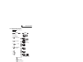
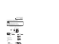
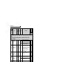
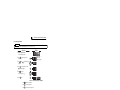
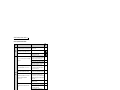
Product checking and parts identification
1 OUTLINE
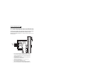
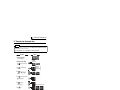
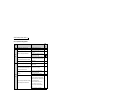
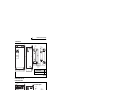
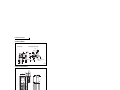
1.1 Product checking and parts identification
Unpack the inverter and check the capacity plate on the front cover and the rating plate on the inverter side face to
ensure that the product agrees with your order and the inverter is intact.
• Inverter Model
FR - F740P - 5.5 K
Symbol Voltage Class
F720P Three-phase 200V class
F740P Three-phase 400V class
Represents inverter
capacity (kW)
Cooling fan
(Refer to page 146)
PU connector
RS-485 terminals
(Refer to page 27)
(Refer to page 26)
Connector for plug-in option connection
(Refer to the Instruction Manual of options.)
Voltage/current input switch
(Refer to page 9)
AU/PTC switchover switch
(Refer to Chapter 4 of the Instruction Manual (Applied).)
EMC filter ON/OFF connector
(Refer to page 10)
1
Operation panel (FR-DU07)
OUTLINE
(Refer to page 6)
Power lamp
Lit when the control circuit
(R1/L11, S1/L21) is supplied
with power.
Alarm lamp
Lit when the inverter is
in the alarm status
(fault).
Control circuit
terminal block
(Refer to page 11)
Main circuit terminal block
Front cover
Charge lamp
Lit when power is
supplied to the main
circuit (Refer to page 11)
(Refer to page 20)
(Refer to page 6)
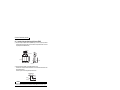
Rating plate
Capacity plate
Combed shaped
wiring cover
Capacity plate
(Refer to page 14)
FR-F740P-5.5K
200V
FR-F740P-5.5K
· DC reactor supplied (75K or higher)
· Eyebolt for hanging the inverter (37K to 315K)
· Fan cover fixing screws (30K or lower)
(Refer to page 171)
400V
Inverter model
Applied motor
capacity
Input rating
Output rating
Serial number
Inverter model Serial number
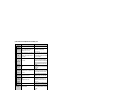
• Accessory
Rating plate
Capacity
Screw Size (mm)
Quantity
2.2K to 5.5K
7.5K to 15K
18.5K to 30K
3.7K, 5.5K
7.5K to 18.5K
22K, 30K
M3 × 35
M4 × 40
M4 × 50
M3 × 35
M4 × 40
M4 × 50
1
2
1
1
2
1
Capacity
Eyebolt Size
Quantity
37K
45K to 160K
185K to 315K
M8
M10
M12
2
2
2
REMARKS
· For removal and reinstallation of covers, refer to page 6.
· For how to find the SERIAL number, refer to page 168.
Harmonic suppression guideline
All models of General-purpose inverters used by specific consumers are covered by "Harmonic suppression guideline for
consumers who receive high voltage or special high voltage". (
Manual (Applied) .)
For further details, refer to Chapter 3 of the Instruction
1
Step of operation
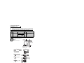
1.2 Step of operation
The inverter needs frequency command and start command. Frequency command (set frequency) determines the
rotation speed of the motor. Turning ON the start command starts the motor to rotate.
Refer to the flow chart below to perform setting.
Step
Step of
off operation
op
operation
Frequency
: Initial setting
Frequency command
Inverter
output
frequency
(Hz)
Frequency
command
ON
Installation/mounting
{Refer to page 8}
Wiring of the power
supply and motor
{Refer to page 11}
Time
(S)
Start command using the PU connector and
RS-485 terminal of the inverter and plug-in
option (Communication)
How
to give a start
command?
Refer to Chapter 4 of
Connect a switch, relay, etc.
to the control circuit
terminal block of the inverter
to give a start command. (External)
Start command with
on the operation panel (PU)
How to
give a frequency
command?
How to
give a frequency
command?
(PU)
Change frequency
with ON/OFF switches
connected to terminals
(multi-speed setting)
(External)
Perform frequency
setting by a current
output device
(Connection across
terminals 4 and 5)
(External)
{Refer to page 54}
{Refer to page 57}
{Refer to page 60}
Set from the
PU (FR-DU07/
FR-PU04/FR-PU07).
the Instruction Manual (Applied) .
Set from the
PU (FR-DU07/
FR-PU04/FR-PU07).
(PU)
{Refer to page 61}
Perform frequency
setting by a voltage
output device
(Connection across
terminals 2 and 5)
(External)
{Refer to page 59}
Change of frequency
with ON/OFF switches
connected to terminals
(multi-speed setting)
(External)
Perform frequency
setting by a current
output device
(Connection across
terminals 4 and 5)
(External)
{Refer to page 65}
{Refer to page 69}
Perform frequency
setting by a voltage
output device
(Connection across
terminals 2 and 5)
(External)
{Refer to page 67}
CAUTION
Check the following points before powering ON the inverter.
· Check that the inverter is installed correctly in a correct place. (Refer to page 8)
· Check that wiring is correct. (Refer to page 9)
· Check that no load is connected to the motor.
·When protecting the motor from overheat by the inverter, set Pr.9 Electronic thermal O/L relay (Refer to
page 52)
·To drive a general-purpose motor with the rated motor frequency of 50Hz, set Pr.3 Base frequency
(Refer to page 53)
2
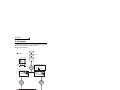
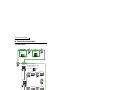
2 INSTALLATION AND WIRING
Three-phase AC power supply
Use within the permissible power supply
specifications of the inverter.
Programmable
controller
(Refer to page 150)
POWER
RUN
T.PASS
SD
ERR
MODE
RUN
ERR
USER
BAT
BOOT
MNG
D.LINK
RD
ERR
RUN
T.PASS
SD
ERR
Human machine interface
Inverter (FR-F700P)
MNG
D.LINK
RD
ERR
The life of the inverter is influenced by surrounding
air temperature. The surrounding air temperature
should be as low as possible within the permissible
range. Especially when mounting the inverter
inside an enclosure, take cautions of the
surrounding air temperature. (Refer to page 8)
Wrong wiring might lead to damage of the inverter.
The control signal lines must be kept fully away
from the main circuit to protect them from noise.
(Refer to page 9)
Refer to page 10 for the built-in EMC filter.
PULL
USB
PULL
Moulded case circuit
breaker (MCCB)
or earth leakage circuit
breaker (ELB), fuse
RS-485 terminal block
The inverter can be connected with a
computer such as a programmable
controller and with GOT (human
machine interface).
They support Mitsubishi inverter
protocol and Modbus-RTU (binary)
protocol.
The breaker must be selected carefully since
an in-rush current flows in the inverter at
power on.
(Refer to page 4)
Magnetic contactor(MC)
Install the magnetic contactor to ensure safety.
Do not use this magnetic contactor to start and stop
the inverter.
Doing so will cause the inverter life to be shortened.
(Refer to page 4)
Reactor (FR-HAL, FR-HEL)
Install reactors to suppress harmonics and to
improve the power factor. An AC reactor (FR-HAL)
(option) is required when installing the inverter near
a large power supply system (1000kVA or more).
The inverter may be damaged if you do not use
reactors.
Select the reactor according to the model.
For the 55K or lower, remove the jumpers across
terminals P/+ and P1 to connect to the DC reactor.
(Refer to Chapter 3 of
the Instruction Manual (Applied) .)
DC reactor
(FR-HEL)
The 55K or lower has a built-in
common mode choke.
P/+ P1 R/L1 S/L2 T/L3 P/+ N/-
For the 75K or higher, a
DC reactor is supplied.
Always install the reactor.
IM connection
IPM connection
U V W
U VW
Earth
(Ground)
(Refer to page 36)
Install an EMC filter (ferrite
core) to reduce the
electromagnetic noise
generated from the inverter.
Effective in the range from
about 0.5MHz to 5MHz.
A wire should be wound four
turns at a maximum.
INSTALLATION AND WIRING
AC reactor
(FR-HAL)
EMC filter
(ferrite core)
(FR-BLF)
2
EMC filter
(ferrite core)
(FR-BSF01, FR-BLF)
(Refer to Chapter 3 of the
Instruction Manual (Applied) .)
(Refer to Chapter 3 of
the Instruction Manual (Applied) .)
Contactor
Example) No-fuse
switch (DSN type)
Brake unit
(FR-BU2, FR-BU*1, MT-BU5*2)
P/+ PR
P/+
High power factor
converter
(FR-HC*1, MT-HC*2)
Power regeneration
common converter
(FR-CV*1)
Power regeneration
converter (MT-RC*2)
Power supply harmonics
can be greatly suppressed.
Install this as required.
Greater braking capability
is obtained.
Install this as required.
(Refer to page 32)
(Refer to page 34 and 35)
*1 Compatible with the 55K or lower.
*2 Compatible with the 75K or higher.
: Install these options as required.
Generalpurpose
motor
Earth
(Ground)
PR
Resistor unit
(FR-BR*1, MT-BR5*2)
The regeneration braking
capability of the inverter can be
exhibited fully.
Install this as required.
(Refer to page 28)
Devices connected
to the output
Earth
Do not install a power
factor correction capacitor,
(Ground)
surge suppressor or EMC filter (capacitor) on the
output side of the inverter.
When installing a moulded case circuit breaker on
the output side of the inverter, contact each
manufacturer for selection of the moulded case
circuit breaker.
Install a contactor in an
application where the IPM
motor is driven by the load
even at power-OFF of the
inverter. Do not open or
close the contactor while
the inverter is running
(outputting).
Dedicated IPM motor
(MM-EFS, MM-EF)
Use the specified motor.
IPM motors cannot be driven
by the commercial power
supply.
(Refer to page 163 and 164)
Earth (Ground)
To prevent an electric shock, always earth
(ground) the motor and inverter.
CAUTION
· Do not install a power factor correction capacitor, surge suppressor or capacitor type filter on the inverter output side. This will
cause the inverter to trip or the capacitor, and surge suppressor to be damaged. If any of the above devices are connected,
immediately remove them.
· Electromagnetic wave interference
The input/output (main circuit) of the inverter includes high frequency components, which may interfere with the communication
devices (such as AM radios) used near the inverter. In this case, set the EMC filter valid to minimize interference.
(Refer to Chapter 2 of
the Instruction Manual (Applied).)
· Refer to the instruction manual of each option and peripheral devices for details of peripheral devices.
· An IPM motor cannot be driven by the commercial power supply.
3
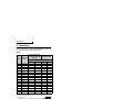
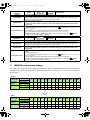
Peripheral devices
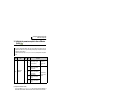
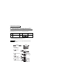
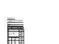
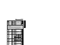
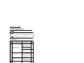
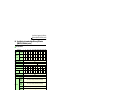
2.1 Peripheral devices
Check the inverter model of the inverter you purchased. Appropriate peripheral devices must be selected according
to the capacity. Refer to the following list and prepare appropriate peripheral devices:
200V class
Motor
Output (kW)
*1
0.75
1.5
2.2
3.7
5.5
7.5
11
15
18.5
22
30
37
45
55
75
90
110
*1
*2
*3
Applicable Inverter
Model
FR-F720P-0.75K
FR-F720P-1.5K
FR-F720P-2.2K
FR-F720P-3.7K
FR-F720P-5.5K
FR-F720P-7.5K
FR-F720P-11K
FR-F720P-15K
FR-F720P-18.5K
FR-F720P-22K
FR-F720P-30K
FR-F720P-37K
FR-F720P-45K
FR-F720P-55K
FR-F720P-75K
FR-F720P-90K
FR-F720P-110K
Moulded Case Circuit Breaker (MCCB) *2
or Earth Leakage Circuit Breaker (ELB) Input Side Magnetic Contactor*3
(NF or NV type)
Power factor improving (AC or DC) reactor
Without
With
Without
With
10A
15A
20A
30A
50A
60A
75A
125A
150A
175A
225A
250A
300A
400A
⎯
⎯
⎯
10A
15A
15A
30A
40A
50A
75A
100A
125A
150A
175A
225A
300A
350A
400A
400A
500A
S-N10
S-N10
S-N10
S-N20, S-N21
S-N25
S-N25
S-N35
S-N50
S-N65
S-N80
S-N95
S-N150
S-N180
S-N220
⎯
⎯
⎯
S-N10
S-N10
S-N10
S-N10
S-N20, S-N21
S-N25
S-N35
S-N50
S-N50
S-N65
S-N80
S-N125
S-N150
S-N180
S-N300
S-N300
S-N400
Selections for use of the Mitsubishi 4-pole standard motor with power supply voltage of 200VAC 50Hz.
Select the MCCB according to the power supply capacity.
MCCB
INV
M
Install one MCCB per inverter.
For using commercial-power supply operation, select a breaker with capacity which allows the motor to be
MCCB
INV
M
directly power supplied.
For installation in the United States, Class RK5, Class J, Class CC, Class L, Class T or any faster acting
fuses or UL 489 Molded Case Circuit Breaker (MCCB) must be provided, in accordance with the National
Electrical Code and any applicable local codes.
For installation in Canada, Class RK5, Class J, Class CC, Class L, Class T or any faster acting fuses or UL
489 Molded Case Circuit Breaker (MCCB) must be provided, in accordance with the Canada Electrical
Code and any applicable provincial codes. (Refer to page 169.)
Magnetic contactor is selected based on the AC-1 class. The electrical durability of magnetic contactor is 500,000 times. When the magnetic
contactor is used for emergency stop during motor driving, the electrical durability is 25 times.
When using the MC for emergency stop during motor driving or using on the motor side during commercial-power supply operation, select the
MC with class AC-3 rated current for the motor rated current.
CAUTION
⋅ When the inverter capacity is larger than the motor capacity, select an MCCB and a magnetic contactor according to the
inverter model, and select cable and reactor according to the motor output.
⋅ When the breaker on the inverter primary side trips, check for the wiring fault (short circuit), damage to internal parts of the
inverter, etc. Identify the cause of the trip, then remove the cause and power ON the breaker.
4
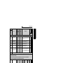
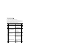
Peripheral devices
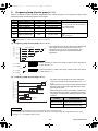
400V class
Applicable Inverter
Model
*1
*1
*2
*3
0.75
1.5
2.2
3.7
5.5
7.5
11
15
18.5
22
30
37
45
55
75
90
110
132
150
160
185
220
250
280
315
355
400
FR-F740P-0.75K
FR-F740P-1.5K
FR-F740P-2.2K
FR-F740P-3.7K
FR-F740P-5.5K
FR-F740P-7.5K
FR-F740P-11K
FR-F740P-15K
FR-F740P-18.5K
FR-F740P-22K
FR-F740P-30K
FR-F740P-37K
FR-F740P-45K
FR-F740P-55K
FR-F740P-75K
FR-F740P-90K
FR-F740P-110K
FR-F740P-132K
FR-F740P-160K
FR-F740P-160K
FR-F740P-185K
FR-F740P-220K
FR-F740P-250K
FR-F740P-280K
FR-F740P-315K
FR-F740P-355K
FR-F740P-400K
450
Moulded Case Circuit Breaker (MCCB) *2
or Earth Leakage Circuit Breaker (ELB) Input Side Magnetic Contactor*3
(NF or NV type)
Power factor improving (AC or DC) reactor
Without
With
Without
With
5A
10A
10A
20A
30A
30A
50A
60A
75A
100A
125A
150A
175A
200A
⎯
⎯
⎯
⎯
⎯
⎯
⎯
⎯
⎯
⎯
⎯
⎯
⎯
5A
10A
10A
15A
20A
30A
40A
50A
60A
75A
100A
125A
150A
175A
225A
225A
225A
400A
400A
400A
400A
500A
600A
600A
700A
800A
900A
S-N10
S-N10
S-N10
S-N10
S-N20, S-N21
S-N20, S-N21
S-N20, S-N21
S-N25
S-N25
S-N35
S-N50
S-N65
S-N80
S-N80
⎯
⎯
⎯
⎯
⎯
⎯
⎯
⎯
⎯
⎯
⎯
⎯
⎯
S-N10
S-N10
S-N10
S-N10
S-N11, S-N12
S-N20, S-N21
S-N20, S-N21
S-N20, S-N21
S-N25
S-N25
S-N50
S-N50
S-N65
S-N80
S-N95
S-N150
S-N180
S-N220
S-N300
S-N300
S-N300
S-N400
S-N600
S-N600
S-N600
S-N600
S-N800
FR-F740P-450K
⎯
1000A
⎯
1000A
Rated product
500
FR-F740P-500K
⎯
1200A
⎯
1000A
Rated product
560
FR-F740P-560K
⎯
1500A
⎯
1200A
Rated product
2
Selections for use of the Mitsubishi 4-pole standard motor with power supply voltage of 400VAC 50Hz.
Select the MCCB according to the power supply capacity.
MCCB
INV
M
Install one MCCB per inverter.
For using commercial-power supply operation, select a breaker with capacity which allows the motor to be
MCCB
INV
M
directly power supplied.
For installation in the United States, Class RK5, Class J, Class CC, Class L, Class T or any faster acting
fuses or UL 489 Molded Case Circuit Breaker (MCCB) must be provided, in accordance with the National
Electrical Code and any applicable local codes.
For installation in Canada, Class RK5, Class J, Class CC, Class L, Class T or any faster acting fuses or UL
489 Molded Case Circuit Breaker (MCCB) must be provided, in accordance with the Canada Electrical
Code and any applicable provincial codes. (Refer to page 169.)
Magnetic contactor is selected based on the AC-1 class. The electrical durability of magnetic contactor is 500,000 times. When the magnetic
contactor is used for emergency stop during motor driving, the electrical durability is 25 times.
When using the MC for emergency stop during motor driving or using on the motor side during commercial-power supply operation, select the
MC with class AC-3 rated current for the motor rated current.
CAUTION
⋅ When the inverter capacity is larger than the motor capacity, select an MCCB and a magnetic contactor according to the
inverter model, and select cable and reactor according to the motor output.
⋅ When the breaker on the inverter primary side trips, check for the wiring fault (short circuit), damage to internal parts of the
inverter, etc. Identify the cause of the trip, then remove the cause and power ON the breaker.
5
INSTALLATION AND WIRING
Motor
Output
(kW)
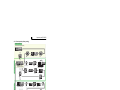
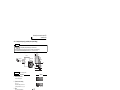
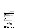
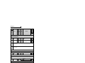
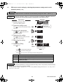
Method of removal and reinstallation of the
front cover
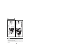
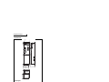
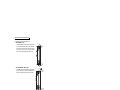
2.2 Method of removal and reinstallation of the front cover
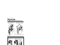
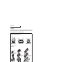
•Removal of the operation panel
1) Loosen the two screws on the operation panel.
(These screws cannot be removed.)
2) Push the left and right hooks of the operation panel
and pull the operation panel toward you to remove.
When reinstalling the operation panel, insert it straight to reinstall securely and tighten the fixed screws of the
operation panel.
FR-F720P-30K or lower, FR-F740P-30K or lower
•Removal
1) Loosen the installation screws of the
front cover.
2) Pull the front cover toward you to remove by pushing an
installation hook using left fixed hooks as supports.
Front cover
Front cover
Installation hook
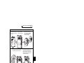
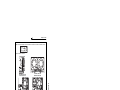
•Reinstallation
1) Insert the two fixed hooks on the left side of
the front cover into the sockets of the
inverter.
2) Using the fixed hooks as supports,
securely press the front cover
against the inverter.
(Although installation can be done
with the operation panel mounted,
make sure that a connector is
securely fixed.)
Front cover
Front cover
6
3) Tighten the installation
screws and fix the front
cover.
Front cover
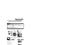
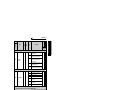
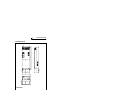
Method of removal and reinstallation of the
front cover
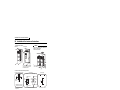
FR-F720P-37K or higher, FR-F740P-37K or higher
•Removal
1) Remove installation screws on
the front cover 1 to remove the
front cover 1.
2) Loosen the installation
screws of the front cover 2.
3) Pull the front cover 2 toward you to
remove by pushing an installation
hook on the right side using left
fixed hooks as supports.
Installation hook
Front cover 1
Front cover 2
•Reinstallation
1) Insert the two fixed hooks on the left side of the
front cover 2 into the sockets of the inverter.
2) Using the fixed hooks as supports, securely
press the front cover 2 against the inverter.
(Although installation can be done with the
operation panel mounted, make sure that a
connector is securely fixed.)
Front cover 2
3) Fix the front cover 2 with the
installation screws.
INSTALLATION AND WIRING
2
Front cover 2
4) Fix the front cover 1 with the
installation screws.
Front cover 1
Front cover 2
REMARKS
⋅ For the FR-F740P-185K or higher, the front cover 1 is separated into two parts.
CAUTION
Fully make sure that the front cover has been reinstalled securely. Always tighten the installation screws of the front cover.
The same serial number is printed on the capacity plate of the front cover and the rating plate of the inverter. Before reinstalling the
front cover, check the serial numbers to ensure that the cover removed is reinstalled to the inverter from where it was removed.
7
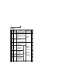
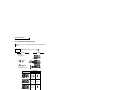
Installation of the inverter and instructions
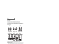
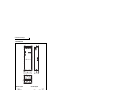
2.3 Installation of the inverter and instructions
• Installation of the Inverter
Installation on the enclosure
30K or lower
CAUTION
37K or higher
⋅ When encasing multiple inverters, install them in
parallel as a cooling measure.
⋅ Install the inverter vertically.
Vertical
Refer to the cleara
nces below.
Fix six points for the FR-F740P-185K
to 400K and fix eight points for the
FR-F740P-450K to 560K.
• Install the inverter under the following conditions.
Clearances (front)
Surrounding air temperature and humidity
Measurement
position
5cm Inverter 5cm
Measurement
position
55K or lower
5cm
20cm or more
10cm or more
5cm
or more *
Temperature: -10°C to 50°C
Humidity: 90% RH maximum
Leave enough clearances as a
cooling measure.
5cm
or more *
Clearances (side)
75K or higher
10cm
or more
10cm or more
10cm
or more
5cm Inverter
or more
*
20cm or more
*1cm or more for 3.7K or lower
*1cm or more for 3.7K or lower
REMARKS
• For replacing the cooling fan of the FR-F740P-185K or higher, 30cm of space is necessary in front of the inverter.
Refer to page 146 for fan replacement.
• The inverter consists of precision mechanical and electronic parts. Never install or handle it in any of the following
conditions as doing so could cause an operation fault or failure.
Direct sunlight
Vertical mounting
(When installing two or
more inverters, install
them in parallel.)
8
Vibration(5.9m/s2 * or more at 10 to
55Hz (directions of X, Y, Z axes))
* 2.9m/s2 or more for the 185K or
higher
Transportation by
holding the front cover
High temperature,
high humidity
Oil mist, flammable
gas, corrosive gas,
fluff, dust, etc.
Horizontal placement
Mounting to
combustible material
Wiring
2.4 Wiring
Terminal connection diagram
*1. DC reactor (FR-HEL)
Be sure to connect the DC reactor
supplied with the 75K or higher.
When a DC reactor is connected
to the 55K or lower, remove the
jumper across P1 and P/+.
Sink logic
Main circuit terminal
Control circuit terminal
Earth
(ground)
Jumper
P1
MC
MCCB
Jumper
*2. To supply power to the
control circuit separately,
remove the jumper across
R1/L11 and S1/L21.
*2
PX*7 N/- CN8*6
U
V
W
ON EMC filter
ON/OFF
OFF connector *8
R1/L11
S1/L21
PR*7
Main circuit
Earth
(Ground)
Control input signals (No voltage input allowed)
Forward
Terminal functions vary
rotation
with the input terminal
start
assignment
Reverse
(Pr. 178 to Pr. 189)
rotation
(Refer to Chapter 4 of the
start
Instruction Manual (Applied))
Jumper
P/+
R/L1
S/L2
T/L3
Three-phase AC
power supply
Resistor unit
(Option)
Brake unit
(Option)
*1
Control circuit
B1
STR
A1
STOP
RUN
RT
SU
MRS
IPF
Output stop
RES *3
Reset
OL
AU
AU
24VDC power supply
(Common for external power supply transistor)
PC
CS PTC
SD
Frequency setting signal (Analog)
3
2
1
Auxiliary (+)
input (-)
Terminal
4 input (+)
(-)
(Current
input)
Connector
Open collector output
2
Running
Terminal functions
vary with the output
Up to frequency terminal assignment
(Pr. 190 to Pr. 194)
Instantaneous (Refer to Chapter 4 of
power failure the Instruction Manual
(Applied))
Overload
FU
Frequency detection
SINK
Terminal 4 input selection
(Current input selection)
Selection of automatic restart
after instantaneous
power failure
Contact input common
*5. It is recommended to use
2W1k when the
frequency setting signal is
changed frequently.
Relay output
Terminal functions
vary with the output
Relay output 1 terminal assignment
(Fault output) (Pr. 195, Pr. 196)
(Refer to Chapter 4 of
the Instruction Manual
(Applied))
Relay output 2
JOG
Second function selection
(Refer to Chapter 4 of the
Instruction Manual (Applied))
Earth
(ground)
cable
*8. The 200V class 0.75K and 1.5K
are not provided with the ON/OFF
connector EMC filter.
RL
Jog operation
*4. Terminal input specifications
can be changed by analog
input specifications switchover
(Pr. 73, Pr. 267). Set the
voltage/current input switch in
the OFF position to select
voltage input (0 to 5V/0 to
10V) and ON to select current
input (0 to 20mA).
M
A2
Low speed
Frequency setting
potentiometer
1/2W1k
*5
Motor
B2
RM
Middle speed
*3. AU terminal can be
used as PTC input
terminal.
C2
RH
SOURCE
Multi-speed
selection
*7. Do not use PR and PX terminals.
Please do not remove the jumper
connected to terminal PR and PX.
C1
STF
Start self-holding selection
High speed
*6. A CN8 (for MT-BU5)
connector is provided
with the 75K or higher.
INSTALLATION AND WIRING
2.4.1
SE
PU
*4 Voltage/current connector
input switch
4 2
10E(+10V)
ON
FM
10(+5V)
OFF
0 to 5VDC Initial value
SD
2 0 to 10VDC
selectable *4
0 to 20mADC
5
AM
(Analog common)
Initial
0 to ±10VDC value
1
0 to ±5VDC selectable *4
Initial
4 to 20mADC value
4 0 to 5VDC
selectable *4
0 to 10VDC
5
+
Indicator
- (Frequency meter, etc.)
Calibration
resistor *9
Moving-coil type
1mA full-scale
(+)
(-)
Analog signal output
(0 to 10VDC)
RS-485 terminals
TXD-
Data transmission
RXD+
SG
Option connector 1
*9. It is not necessary
when calibrating the
indicator from the
operation panel.
TXD+
RXD-
for plug-in option
connection
Open collector output common
Sink/source common
Terminating
resistor VCC
Data reception
GND
5V (Permissible load
current 100mA)
CAUTION
· To prevent a malfunction due to noise, keep the signal cables more than 10cm away from the power cables. Also separate the
main circuit wire of the input side and the output side.
· After wiring, wire offcuts must not be left in the inverter.
Wire offcuts can cause an alarm, failure or malfunction. Always keep the inverter clean.
When drilling mounting holes in an enclosure etc. take care not to allow chips and other foreign matter to enter the inverter.
· Set the voltage/current input switch correctly. Operation with a wrong setting may cause a fault, failure or malfunction.
9
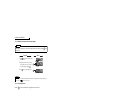
Wiring
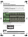
2.4.2
EMC filter
This inverter is equipped with a built-in EMC filter (capacitive filter) and common mode choke.
The EMC filter is effective for reduction of air-propagated noise on the input side of the inverter.
The EMC filter is factory-set to disable (OFF). To enable it, fit the EMC filter ON/OFF connector to the ON position.
The input side common mode choke, built-in the 55K or lower inverter, is always valid regardless of ON/OFF of the
EMC filter ON/OFF connector.
5.5K or lower
EMC filter OFF
(initial setting)
FR-F720P-2.2K to 5.5K
FR-F740P-0.75K to 5.5K
15K or higher
7.5K, 11K
EMC filter ON
EMC filter OFF
(initial setting)
FR-F720P-7.5K, 11K
FR-F740P-7.5K, 11K
EMC filter ON
FR-F720P-15K
FR-F740P-15K, 18.5K
FR-F720P-18.5K to 30K
FR-F740P-22K, 30K
EMC filter OFF
(initial setting)
EMC filter ON
FR-F720P-37K or higher
FR-F740P-37K or higher
EMC filter
ON/OFF
connector
U
V
W
The FR-F720P-0.75K and 1.5K are not provided with the EMC filter ON/OFF connector. (Always ON)
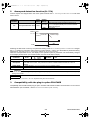
<How to disconnect the connector>
(1) Before removing a front cover, check to make sure that the indication of the inverter operation panel is OFF, wait
for at least 10 minutes after the power supply has been switched OFF, and check that there are no residual voltage
using a tester or the like. (For the front cover removal method, refer to page 6.)
(2) When disconnecting the connector, push the fixing tab and pull the connector straight without pulling the cable or
forcibly pulling the connector with the tab fixed. When installing the connector, also engage the fixing tab securely.
If it is difficult to disconnect the connector, use a pair of long-nose pliers, etc.
EMC filter
ON/OFF connector
(Side view)
Disengage connector fixing tab.
With tab disengaged,
pull up connector straight.
CAUTION
⋅ Fit the connector to either ON or OFF.
⋅ Enabling (turning ON) the EMC filter increases leakage current. (Refer to Chapter 3 of
the Instruction Manual (Applied))
WARNING
While power is ON or when the inverter is running, do not open the front cover. Otherwise you may get an electric shock.
10
Wiring
Specification of main circuit terminal
Terminal
Symbol
Terminal Name
R/L1,
S/L2,
T/L3
AC power input
U, V, W
Inverter output
R1/L11,
S1/L21
Power supply for
control circuit
Connect to the commercial power supply.
Keep these terminals open when using the high power
factor converter (FR-HC, MT-HC) or power regeneration
common converter (FR-CV).
Connect a three-phase squirrel-cage motor or dedicated
IPM motor.
Connected to the AC power supply terminals R/L1 and S/
L2. To retain the fault display and fault output or when
using the high power factor converter (FR-HC, MT-HC) or
power regeneration common converter (FR-CV), remove
the jumpers from terminals R/L1 and R1/L11, and S/L2
and S1/L21, and apply external power to these terminals.
The power capacity necessary when separate power is
supplied from R1/L11 and S1/L21 differs according to the
inverter capacity.
200V class
400V class
15K or lower
60VA
60VA
18.5K
80VA
60VA
11
11
18
22K or higher
80VA
80VA
Connect the brake unit (FR-BU2, FR-BU, BU and MTBU5), power regeneration common converter (FR-CV),
high power factor converter (FR-HC and MT-HC) or power
regeneration converter (MT-RC).
For the 55K or lower, remove the jumper across terminals
P/+ and P1, and connect the DC reactor. (Be sure to
DC reactor
connect the DC reactor supplied with the 75K or higher.)
connection
When a DC reactor is not connected, the jumper across
terminals P/+ and P1 should not be removed.
Please do not remove or use terminals PR and PX or the jumper connected.
For earthing (grounding) the inverter chassis. Must be
Earth (ground)
earthed (grounded).
Brake unit
connection
P/+, N/-
P/+, P1
PR, PX
2.4.4
Refer to
Page
Description
28
2
36
—
17
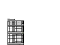
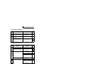
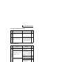
Terminal arrangement of the main circuit terminal, power supply and the motor
wiring
200V class
FR-F720P-0.75K, 1.5K
FR-F720P-2.2K to 5.5K
Jumper
Jumper
Screw size (M4)
R/L1 S/L2 T/L3
Jumper
Screw size (M4)
PR
Jumper
R1/L11 S1/L21 N/-
P/+
M
Power supply Motor
N/-
M
Charge lamp
As this is an inside cover fixing screw,
do not remove it.
Power
supply
P/+
PR
PX
R1/L11 S1/L21
PX
Screw size
(M4)
R/L1 S/L2 T/L3
Screw size
(M4)
Charge lamp
Motor
11
INSTALLATION AND WIRING
2.4.3
Wiring
FR-F720P-7.5K, 11K
FR-F720P-15K
R1/L11 S1/L21
Screw size
(M4)
Charge lamp
Jumper
Charge lamp
*
*
Jumper
*
N/-
P/+ PR
R1/L11 S1/L21
Jumper
Jumper
P/+
Screw size (M5)
Screw size
(M5)
PX
*
R/L1 S/L2 T/L3
R/L1 S/L2 T/L3
N/-
M
M
Power supply
Motor
Screw size (M5)
* Screw size of terminal
R1/L11, S1/L21, PR
and PX is M4.
PR
Motor
Power supply
Screw size (M5)
FR-F720P-18.5K to 30K
FR-F720P-37K to 55K
R1/L11 S1/L21
Screw size
(M4)
R1/L11 S1/L21
Screw size (M4)
Screw size
Charge lamp
(M6 for 18.5K,
Jumper
M8 for 22K and 30K)
PR
N/-
P/+
R/L1 S/L2 T/L3
Jumper
Screw size
(M8 for 37K, M10 for 45K and 55K)
Jumper
M
Power supply
Charge lamp
Motor
Screw size (M6)
R/L1 S/L2 T/L3
Power
supply
FR-F720P-75K to 110K
R1/L11 S1/L21 Screw size (M4)
Charge lamp
Jumper
Screw size (M12)
R/L1 S/L2 T/L3
N/-
P/+
P/+
Screw size
(M10)
P/+
Power supply
Screw size (M12)
(for option)
12
M
Motor
DC reactor
N/-
P/+
Jumper
Screw size
(M6 for 37K,
M8 for 45K and 55K)
M
Motor
Wiring
400V class
FR-F740P-0.75K to 5.5K
FR-F740P-7.5K, 11K
Jumper
Screw size (M4)
Jumper
R/L1 S/L2 T/L3
P/+
N/-
PR
Charge lamp
PX
R1/L11 S1/L21
N/-
Jumper
Screw size
(M4)
M
Power
supply
P/+ PR
Jumper
R1/L11 S1/L21
Charge lamp
Screw size
(M4)
Motor
PX
R/L1 S/L2 T/L3
M
Motor
Power supply
Screw size
(M4)
FR-F740P-15K, 18.5K
FR-F740P-22K, 30K
R1/L11 S1/L21
Screw size
(M4)
R1/L11 S1/L21
Screw size (M4)
Charge lamp
Jumper
Charge lamp
PR
Jumper
Screw size (M6)
Jumper
2
P/+
N/-
R/L1 S/L2 T/L3
R/L1 S/L2 T/L3
N/-
M
PR
Power supply
P/+
INSTALLATION AND WIRING
Screw size (M5)
Jumper
Motor
M
Motor
Power supply
Screw size (M5)
FR-F740P-37K to 55K
Screw size (M6)
FR-F740P-75K to 110K
R1/L11 S1/L21
Screw size(M4)
Charge lamp
R1/L11 S1/L21
Screw size (M4)
Jumper
Charge lamp
Jumper
Screw size (M6 for 37K,
M8 for 45K and 55K)
Screw size
Screw size
(M8 for 75K,
(M8 for 75K,
M10 for 90K and 110K) Screw size (M10) M10 for 90K and 110K)
R/L1 S/L2 T/L3
R/L1 S/L2 T/L3
Power
supply
N/-
P/+
Jumper
Screw size
(M6 for 37K,
M8 for 45K and 55K)
N/-
P/+
P/+
M
Motor
Power
supply
M
Motor
DC reactor
Screw size
(M8 for 75K,
M10 for 90K and 110K)
13
Wiring
FR-F740P-132K to 220K
FR-F740P-250K to 560K
R1/L11 S1/L21 Screw size (M4)
R1/L11 S1/L21 Screw size (M4)
Charge lamp
Charge lamp
Jumper
Jumper
Screw size
(M10 for 132K and 160K,
M12 for 185K and 220K)
R/L1 S/L2 T/L3
N/-
P/+
Screw size (M12)
P/+
R/L1 S/L2 T/L3 N/-
P/+
Screw size
(M10)
P/+
Power supply
Screw size (M12)
(for option)
M
P/+
Motor
DC reactor
M
Motor
Power supply
DC reactor
Screw size (M10)
CAUTION
· The power supply cables must be connected to R/L1, S/L2, T/L3. (Phase sequence needs not to be matched.) Never connect
the power cable to the U, V, W of the inverter. Doing so will damage the inverter.
· Connect the motor to U, V, W. At this time, turning ON the forward rotation switch (signal) rotates the motor in the
counterclockwise direction when viewed from the motor shaft.
· When wiring the inverter main circuit conductor of the 250K or higher, tighten a nut from the right side of the conductor. When
wiring two wires, place wires on both sides of the conductor. (Refer to the drawing below.) For wiring, use bolts (nuts) provided
with the inverter.
• Handling of the wiring cover
(FR-F720P-18.5K, 22K, FR-F740P-22K, 30K)
For the hook of the wiring cover, cut off the necessary
parts using a pair of long-nose pliers etc.
CAUTION
Cut off the same number of lugs as wires. If parts where
no wire is put through has been cut off (10mm or more),
protective structure (JEM1030) becomes an open type
(IP00).
14
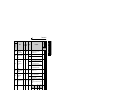
Wiring
(1) Cable size and other specifications of the main circuit terminals and the earthing terminal
Select the recommended cable size to ensure that a voltage drop will be 2% or less.
If the wiring distance is long between the inverter and motor, a main circuit cable voltage drop will cause the motor
torque to decrease especially at the output of a low frequency.
The following table indicates a selection example for the wiring length of 20m.
200V class (when input power supply is 220V)
FR-F720P-0.75K
to 2.2K
FR-F720P-3.7K
FR-F720P-5.5K
FR-F720P-7.5K
FR-F720P-11K
FR-F720P-15K
FR-F720P-18.5K
FR-F720P-22K
FR-F720P-30K
FR-F720P-37K
FR-F720P-45K
FR-F720P-55K
FR-F720P-75K
FR-F720P-90K
FR-F720P-110K
*1
*2
*3
*4
*5
Cable Sizes
Crimping
Terminal
2
AWG/MCM *2
HIV, etc. (mm ) *1
PVC, etc. (mm2) *3
R/L1,
S/L2,
T/L3
U, V, W
R/L1,
S/L2,
T/L3
U, V, W
P/+, P1
Earthing
cable
R/L1,
S/L2,
T/L3
U, V, W
R/L1,
S/L2,
T/L3
U, V, W
Earthing
cable
2-4
2
2
2
2
14
14
2.5
2.5
2.5
3.5
5.5
8
14
22
38
38
60
80
100
100
125
150
2×100
3.5
5.5
14
14
22
38
38
60
80
100
100
150
2×100
2×100
3.5
5.5
5.5
14
14
22
22
22
22
38
38
38
38
38
12
10
6
6
4
2
2
1/0
3/0
4/0
4/0
250
2×4/0
2×4/0
12
10
8
6
6 (*5)
2
2
1/0
3/0
4/0
4/0
250
2×4/0
2×4/0
4
6
16
16
25
35
35
50
70
95
95
⎯
⎯
⎯
4
6
10
16
25
35
35
50
70
95
95
⎯
⎯
⎯
4
6
16
16
16
25
25
25
35
50
50
⎯
⎯
⎯
M4
1.5
2-4
M4
M4
M5
M5
M5
M6
M8 (M6)
M8 (M6)
M8 (M6)
M10 (M8)
M10 (M8)
M12 (M10)
M12 (M10)
M12 (M10)
1.5
1.5
2.5
2.5
2.5
4.4
7.8
7.8
7.8
14.7
14.7
24.5
24.5
24.5
5.5-4
5.5-4
14-5
14-5
22-5
38-6
38-8
60-8
80-8
100-10
100-10
150-12
150-12
100-12
5.5-4
3.5
5.5-4
5.5
8-5
14
14-5
14
22-5
22
38-6
38
38-8
38
60-8
60
80-8
80
100-10 100
100-10 100
150-12 125
150-12 150
100-12 2×100
The cable size is that of the cable (HIV cable (600V class 2 vinyl-insulated cable) etc.) with continuous maximum permissible temperature of
75°C. Assumes that the surrounding air temperature is 50°C or less and the wiring distance is 20m or less.
The recommended cable size is that of the cable (THHW cable) with continuous maximum permissible temperature of 75°C. Assumes that the
surrounding air temperature is 40°C or less and the wiring distance is 20m or less.
(Selection example for use mainly in the United States.)
For the 15K or lower, the recommended cable size is that of the cable (PVC cable) with continuous maximum permissible temperature of 70°C.
Assumes that the surrounding air temperature is 40°C or less and the wiring distance is 20m or less.
For the 18.5K or higher, the recommended cable size is that of the cable (XLPE cable) with continuous maximum permissible temperature of
90°C. Assumes that the surrounding air temperature is 40°C or less and wiring is performed in an enclosure.
(Selection example for use mainly in Europe.)
The terminal screw size indicates the terminal size for R/L1, S/L2, T/L3, U, V, W, and a screw for earthing (grounding).
A screw for earthing (grounding) of the 22K or higher is indicated in ( ).
When connecting the option unit to P/+, P1, N/-, use THHN cables for the option and terminals R/L1, S/L2, T/L3, U, V, W.
15
2
INSTALLATION AND WIRING
Terminal Tightening
Applicable
Screw
Torque
Inverter Model
Size *4
N·m
Wiring
400V class (when input power supply is 440V)
Applicable
Inverter Model
Crimping
Terminal Tightening (Compression)
Terminal
Screw
Torque
R/L1,
Size *4
N·m
S/L2,
U, V, W
T/L3
FR-F740P-0.75K
to 3.7K
FR-F740P-5.5K
FR-F740P-7.5K
FR-F740P-11K
FR-F740P-15K
FR-F740P-18.5K
FR-F740P-22K
FR-F740P-30K
FR-F740P-37K
FR-F740P-45K
FR-F740P-55K
FR-F740P-75K
FR-F740P-90K
FR-F740P-110K
FR-F740P-132K
FR-F740P-160K
FR-F740P-185K
FR-F740P-220K
FR-F740P-250K
FR-F740P-280K
FR-F740P-315K
FR-F740P-355K
FR-F740P-400K
FR-F740P-450K
FR-F740P-500K
FR-F740P-560K
*1
*2
*3
*4
Cable Sizes
HIV, etc. (mm2) *1
PVC, etc. (mm2) *3
AWG/MCM *2
R/L1,
S/L2,
T/L3
U, V, W
P/+, P1
Earthing
cable
R/L1,
S/L2,
T/L3
U, V, W
R/L1,
S/L2,
T/L3
U, V, W
Earthing
cable
2.5
2.5
M4
1.5
2-4
2-4
2
2
2
2
14
14
2.5
M4
M4
M4
M5
M5
M6
M6
M6
M8
M8
M8
M10
M10
M10
M10
M12 (M10)
M12 (M10)
M12 (M10)
M12 (M10)
M12 (M10)
M12 (M10)
M12 (M10)
M12 (M10)
M12 (M10)
M12 (M10)
1.5
1.5
1.5
2.5
2.5
4.4
4.4
4.4
7.8
7.8
7.8
14.7
14.7
14.7
14.7
24.5
24.5
46
46
46
46
46
46
46
46
2-4
5.5-4
5.5-4
8-5
14-5
14-6
22-6
22-6
38-8
60-8
60-8
60-10
80-10
100-10
150-10
150-12
100-12
100-12
150-12
150-12
200-12
C2-200
C2-250
C2-250
C2-200
2-4
5.5-4
5.5-4
8-5
8-5
14-6
22-6
22-6
38-8
60-8
60-8
60-10
80-10
100-10
150-10
150-12
100-12
100-12
150-12
150-12
200-12
C2-200
C2-250
C2-250
C2-200
2
3.5
5.5
8
14
14
22
22
38
60
60
60
80
100
125
150
2×100
2×100
2×125
2×150
2×200
2×200
2×250
2×250
3×200
2
3.5
5.5
8
8
14
22
22
38
60
60
60
80
100
125
150
2×100
2×100
2×125
2×150
2×200
2×200
2×250
2×250
3×200
3.5
3.5
5.5
8
14
22
22
22
38
60
60
80
100
100
150
2×100
2×100
2×125
2×125
2×150
2×200
2×200
2×250
3×200
3×200
3.5
3.5
8
8
14
14
14
14
22
22
38
38
38
38
38
38
38
38
38
60
60
60
60
100
100
12
12
10
8
6
6
4
4
1
1/0
1/0
3/0
3/0
4/0
250
300
2×4/0
2×4/0
2×250
2×300
2×350
2×400
2×500
2×500
3×350
14
12
10
8
8
6
4
4
2
1/0
1/0
3/0
3/0
4/0
250
300
2×4/0
2×4/0
2×250
2×300
2×350
2×400
2×500
2×500
3×350
2.5
4
6
10
16
16
25
25
50
50
50
50
70
95
120
150
2×95
2×95
2×120
2×150
2×185
2×185
2×240
2×240
3×185
2.5
4
4
4
6
10
10
10
10
16
16
16
25
16
25
16
50
25
50
25
50
25
50
25
70
35
95
50
120
70
150
95
2×95
95
2×95
95
2×120 120
2×150 150
2×185 2×95
2×185 2×95
2×240 2×120
2×240 2×120
3×185 2×150
For the FR-F740P-55K or lower, the recommended cable size is that of the cable (e.g. HIV cable (600V class 2 vinyl-insulated cable)) with continuous
maximum permissible temperature of 75°C. Assumes that the surrounding air temperature is 50°C or less and the wiring distance is 20m or less.
For the FR-F740P-75K or higher, the recommended cable size is that of the cable (e.g. LMFC (heat resistant flexible cross-linked polyethylene insulated
cable)) with continuous maximum permissible temperature of 90°C. Assumes that the surrounding air temperature is 50°C or less and wiring is performed
in an enclosure.
For the FR-F740P-45K or lower, the recommended cable size is that of the cable (THHW cable) with continuous maximum permissible temperature of
75°C. Assumes that the surrounding air temperature is 40°C or less and the wiring distance is 20m or less.
For the FR-F740P-55K or higher, the recommended cable size is that of the cable (THHN cable) with continuous maximum permissible temperature of
90°C. Assumes that the surrounding air temperature is 40°C or less and wiring is performed in an enclosure.
(Selection example for use mainly in the United States.)
For the FR-F740P-45K or lower, the recommended cable size is that of the cable (PVC cable) with continuous maximum permissible temperature of
70°C. Assumes that the surrounding air temperature is 40°C or less and the wiring distance is 20m or less.
For the FR-F740P-55K or higher, the recommended cable size is that of the cable (XLPE cable) with continuous maximum permissible temperature of
90°C. Assumes that the surrounding air temperature is 40°C or less and wiring is performed in an enclosure.
(Selection example for use mainly in the Europe.)
The terminal screw size indicates the terminal size for R/L1, S/L2, T/L3, U, V, W, and a screw for earthing (grounding).
A screw for earthing (grounding) of the 185K or higher is indicated in ( ).
The line voltage drop can be calculated by the following formula:
Line voltage drop [V]=
3 × wire resistance[mΩ/m] × wiring distance[m] × current[A]
1000
Use a larger diameter cable when the wiring distance is long or when it is desired to decrease the voltage drop (torque
reduction) in the low speed range.
CAUTION
· Tighten the terminal screw to the specified torque.
A screw that has been tighten too loosely can cause a short circuit or malfunction.
A screw that has been tighten too tightly can cause a short circuit or malfunction due to the unit breakage.
· Use crimping terminals with insulation sleeve to wire the power supply and motor.
16
Wiring
(2) Notes on earthing (grounding)
• Leakage currents flow in the inverter. To prevent an electric shock, the inverter and motor must be earthed (grounded). This
inverter must be earthed (grounded). Earthing (Grounding) must conform to the requirements of national and local safety
regulations and electrical codes. (NEC section 250, IEC 536 class 1 and other applicable standards)
A neutral-point earthed (grounded) power supply for 400V class inverter in compliance with EN standard must be used.
• Use the dedicated earth (ground) terminal to earth (ground) the inverter.
(Do not use the screw in the casing, chassis, etc.)
• Use the thickest possible earth (ground) cable. Use the cable whose size is equal to or greater than that indicated in page
15 and minimize the cable length. The earthing (grounding) point should be as near as possible to the inverter.
To be compliant with the EU Directive (Low Voltage Directive), earth (ground) the inverter according to
the instructions on page 171.
(3) Total wiring length
Under general-purpose motor control
Connect one or more general-purpose motors within the total wiring length shown in the following table.
Pr. 72 PWM frequency selection Setting
(carrier frequency)
0.75K
1.5K
2.2K or Higher
2 (2kHz) or lower
3 (3kHz) or higher
300m
200m
500m
300m
500m
500m
Total wiring length when using a general-purpose motor (2.2K or higher)
300m
2
300m + 300m = 600m
When driving a 400V class motor by the inverter, surge voltages attributable to the wiring constants may occur at the
motor terminals, deteriorating the insulation of the motor. Take the following measures 1) or 2) in this case.
1) Use a "400V class inverter-driven insulation-enhanced motor" and set frequency in Pr. 72 PWM frequency selection
according to wiring length.
Wiring Length
Pr. 72 PWM frequency selection Setting
(carrier frequency)
50m or less
50m to 100m
exceeding 100m
14.5kHz or lower
9kHz or lower
4kHz or lower
2) Connect the surge voltage suppression filter (FR-ASF-H/FR-BMF-H) to the 55K or lower and the sine wave filter
(MT-BSL/BSC) to the 75K or higher on the inverter output side.
Under IPM motor control
Connect an IPM motor within the total wiring length of 100m.
Use one dedicated IPM motor for one inverter. Multiple IPM motors cannot be connected to an inverter.
To drive a 400V-class motor with an inverter under IPM control, set Pr.72 PWM frequency selection according to the wiring
length as shown below.
Applied inverter
FR-F740P-0.75K to 1.5K
Other
50m or less
Wiring Length
50m to 100m
0(2kHz) to 15(14kHz)
0(2kHz) to 15(14kHz)
5(2kHz) or lower
9(6kHz) or lower
17
INSTALLATION AND WIRING
300m
500m or less
Wiring
CAUTION
· Especially for long-distance wiring, the inverter may be affected by a charging current caused by the stray capacitances of the
wiring, leading to a malfunction of the overcurrent protective function or fast response current limit function or a malfunction or fault
of the equipment connected on the inverter output side. If fast-response current limit function malfunctions, disable this function.
(For Pr.156 Stall prevention operation selection, refer to Chapter 4 of the
Instruction Manual (Applied).)
· For details of Pr. 72 PWM frequency selection , refer to Chapter 4 of
the Instruction Manual (Applied). (When using an optional
sine wave filter (MT-BSL/BSC) for the 75K or higher, set "25" in Pr.72 (2.5kHz). (Sine wave filter can be only used with a generalpurpose motor.)
· The surge voltage suppression filter (FR-ASF-H/FR-BMF-H) option and sine wave filter (MT-BSL/BSC) cannot be used under
IPM motor control, so do not connect them.
· For explanation of surge voltage suppression filter (FR-ASF-H/FR-BMF-H) and sine wave filter (MT-BSL/BSC), refer to the
manual of each option.
(4) Cable size of the control circuit power supply (terminal R1/L11, S1/L21)
· Terminal Screw Size: M4
· Cable size: 0.75mm2 to 2mm2
· Tightening torque: 1.5N·m
(5) When connecting the control circuit and the main circuit separately to the power supply
<Connection diagram>
When fault occurs, opening of the electromagnetic contactor (MC) on the
inverter power supply side results in power loss in the control circuit,
disabling the fault output signal retention. Terminals R1/L11 and S1/L21 are
provided for when retention of a fault signal is required. In this case, connect
the power supply terminals R1/L11 and S1/L21 of the control circuit to the
primary side of the MC.
Do not connect the power cable to incorrect terminals. Doing so may
damage the inverter.
MC
R/L1 Inverter
S/L2
T/L3
R1/L11
S1/L21
Remove the jumper
• FR-F720P-0.75K to 5.5K, FR-F740P-0.75K to 5.5K
1) Loosen the upper screws.
2) Remove the lower screws.
3) Remove the jumper
4) Connect the separate power
supply cable for the control
circuit to the lower terminals
(R1/L11, S1/L21).
3)
1)
R/L1
S/L2
T/L3
2)
4)
R1/L11
S1/L21
R1/L11
Main circuit terminal block
18
S1/L21
Wiring
• FR-F720P-7.5K, 11K, FR-F740P-7.5K, 11K
1) Remove the upper screws.
2) Remove the lower screws.
3) Remove the jumper.
4) Connect the separate power
supply cable for the control
circuit to the upper terminals
(R1/L11, S1/L21).
3)
1)
R1/L11
S1/L21
R1/L11
S1/L21
2)
4)
R/
L1
S/
L2
T/
L3
Main circuit
terminal block
• FR-F720P-15K, FR-F740P-15K or higher
R1/ S1/
L11 L21 Power supply
terminal block
for the control circuit
R/L1S/L2 T/L3
3)
Power supply terminal block
for the control circuit
2
R1/L11
S1/L21
INSTALLATION AND WIRING
1) Remove the upper screws.
2) Remove the lower screws.
3) Pull the jumper toward you to
remove.
4) Connect the separate power supply
cable for the control circuit to the
upper terminals (R1/L11, S1/L21).
MC
Main power supply
FR-F720P-15K
FR-F740P-15K, 18.5K
1)
2)
4)
FR-F720P-18.5K to 30K FR-F720P-37K or higher
FR-F740P-37K or higher
FR-F740P-22K, 30K
Power supply
terminal block for
the control circuit
U
V
W
CAUTION
· Be sure to use the inverter with the jumpers across terminals R/L1 and R1/L11, and S/L2 and S1/L21 removed when supplying
power from other sources. The inverter may be damaged if you do not remove the jumper.
· The voltage should be the same as that of the main control circuit when the control circuit power is supplied from other than the
primary side of the MC.
· The power capacity necessary when separate power is supplied from R1/L11 and S1/L21 differs according to the inverter
capacity.
200V class
400V class
15K or lower
60VA
60VA
18.5K
80VA
60VA
22K or higher
80VA
80VA
· If the main circuit power is switched OFF (for 0.1s or more) then ON again, the inverter resets and a fault output will not be held.
19
Wiring
2.4.5
Control circuit terminals
indicates that terminal functions can be selected using Pr. 178 to Pr. 196 (I/O terminal function selection) (Refer to Chapter 4 of
the Instruction Manual (Applied).)
Type
(1) Input signals
Terminal
Symbol
STF
STR
STOP
RH,
RM, RL
JOG
Contact input
RT
Forward
rotation start
Reverse
rotation start
Start selfholding
selection
Multi-speed
selection
Jog mode
selection
Second
function
selection
MRS
Output stop
RES
Reset
Terminal 4
input selection
AU
PTC input
CS
SD
PC
20
Terminal
Name
Selection of
automatic
restart after
instantaneous
power failure
Contact input
common (sink)
(initial setting)
External
transistor
common
(source)
24VDC power
supply common
External
transistor
common (sink)
(initial setting)
Contact input
common
(source)
24VDC power
supply
Rated
Specifications
Description
Turn ON the STF signal to start forward
rotation and turn it OFF to stop.
Turn ON the STR signal to start reverse
rotation and turn it OFF to stop.
When the STF and
STR signals are turned
ON simultaneously, the
stop command is given.
61
Turn ON the STOP signal to self-hold the start signal.
Multi-speed can be selected according to the combination of RH,
RM and RL signals.
Turn ON the JOG signal to select Jog operation (initial setting)
and turn ON the start signal (STF or STR) to start Jog operation.
Turn ON the RT signal to select second function.
When the second function such as "second torque boost" and
"second V/F (base frequency)" are set, turning ON the RT signal
selects these functions.
Turn ON the MRS signal (20ms or more) to stop the inverter
output.
Use to shut off the inverter output when stopping the motor by
electromagnetic brake.
Use to reset fault output provided when fault occurs.
Turn ON the RES signal for more than 0.1s, then turn it OFF.
In the initial status, reset is set always-enabled. By setting Pr.75,
reset can be set enabled only at fault occurrence. Inverter
recovers about 1s after the reset is released.
Terminal 4 is valid only when the AU signal is turned ON. (The
frequency setting signal can be set between 0 and 20mADC.)
Turning the AU signal ON makes terminal 2 (voltage input)
invalid.
AU terminal is used as PTC input terminal (thermal protection of
the motor). When using it as PTC input terminal, set the AU/PTC
switch to PTC.
When the CS signal is left ON, the inverter restarts automatically at
power restoration. Note that restart setting is necessary for this
operation. In the initial setting, a restart is disabled.
Refer to
Page
*2
65
*2
*2
Input resistance
4.7kΩ
Voltage at
opening: 21 to
27VDC
Contacts at
short-circuited: 4
to 6mADC
*2
116
69
*2
*2
(Refer to
Pr. 57 Restart coasting time in Chapter 4 of the Instruction
Manual (Applied).)
Common terminal for contact input terminal (sink logic) and terminal
FM.
Connect this terminal to the power supply common terminal of a
transistor output (open collector output) device, such as a
programmable controller, in the source logic to avoid malfunction by
undesirable currents.
Common output terminal for 24VDC 0.1A power supply (PC terminal).
Isolated from terminals 5 and SE.
Connect this terminal to the power supply common terminal of a
transistor output (open collector output) device, such as a
programmable controller, in the sink logic to avoid malfunction by
undesirable currents.
Common terminal for contact input terminal (source logic).
Can be used as 24VDC 0.1A power supply.
--------------------
—
Power supply
voltage range
19.2 to 28.8VDC
Permissible load
current 100mA
24
Terminal
Symbol
10E
10
Frequency setting
2
4
Terminal
Name
Frequency
setting power
supply
Description
When connecting the frequency setting potentiometer at an initial
status, connect it to terminal 10.
Change the input specifications of terminal 2 when connecting it
to terminal 10E. (Refer to Pr. 73 Analog input selection in Chapter 4
of
Frequency
setting
(voltage)
Frequency
setting
(current)
the Instruction Manual (Applied).)
Inputting 0 to 5VDC (or 0 to 10V, 0 to 20mA) provides the
maximum output frequency at 5V (10V, 20mA) and makes input
and output proportional. Use Pr. 73 to switch from among input 0
to 5VDC (initial setting), 0 to 10VDC, and 0 to 20mA.
Set the voltage/current input switch in the ON position to select
current input (0 to 20mA).*1
Inputting 4 to 20mADC (or 0 to 5V, 0 to 10V) provides the
maximum output frequency at 20mA (5V, 10V) makes input and
output proportional. This input signal is valid only when the AU
signal is ON (terminal 2 input is invalid). Use Pr. 267 to switch
from among input 4 to 20mA (initial setting), 0 to 5VDC, and 0 to
10VDC. Set the voltage/current input switch in the OFF position
to select voltage input (0 to 5V/0 to 10V).*1
(Refer to Chapter 4 of
the Instruction Manual (Applied).)
Rated
Specifications
10VDC
Permissible load
current 10mA
5VDC
Permissible load
current 10mA
Voltage input:
Input resistance
10kΩ ± 1kΩ
Maximum
permissible
voltage 20VDC
Current input:
Input resistance
245Ω ± 5Ω
Maximum
permissible
current 30mA
Refer to
Page
*2
59, 67
59, 67
Voltage/current
input switch
2
4
60, 69
Switch 1
Switch 2
1
Frequency
setting
auxiliary
Inputting 0 to ±5 VDC or 0 to ±10VDC adds this signal to terminal
2 or 4 frequency setting signal. Use Pr.73 to switch between the
input 0 to ±5VDC and 0 to ±10VDC (initial setting).
Input resistance
10kΩ ± 1kΩ
Maximum
permissible voltage
± 20VDC
*2
5
Frequency
setting
common
Common terminal for frequency setting signal (terminal 2, 1 or 4)
and analog output terminal AM. Do not earth (ground).
--------------------
------
2
*1
Set Pr. 73, Pr. 267, and a voltage/current input switch correctly, then input an analog signal in accordance with the setting.
Applying a voltage signal with voltage/current input switch ON (current input is selected) or a current signal with switch OFF (voltage input is
selected) could cause component damage of the inverter or analog circuit of signal output devices.
*2
Refer to Chapter 4 of
the Instruction Manual (Applied).
21
INSTALLATION AND WIRING
Type
Wiring
Wiring
Analog
Pulse
Open collector
Relay
Type
(2) Output signals
Terminal
Symbol
Terminal
Name
Description
Rated Specifications
A1,
B1,
C1
Relay output 1
(Fault output)
1 changeover contact output indicates that the
inverter’s protective function has activated and the
output stopped.
Fault: No conduction between B and C (conduction
between A and C)
Normal: Conduction between B and C (No conduction
between A and C)
Contact capacity: 230VAC 0.3A
(Power factor=0.4)
30VDC 0.3A
A2,
B2,
C2
Relay output 2
1 changeover contact output
RUN
Inverter
running
SU
Up to
frequency
OL
Overload
warning
IPF
Instantaneous
power failure
FU
Frequency
detection
SE
Open collector
Common terminal for terminals RUN, SU, OL, IPF, FU
output common
FM
For meter
AM
Analog signal
output
* Refer to Chapter 4 of
*
*
Switched low when the inverter output frequency is
equal to or higher than the starting frequency (initial
value 0.5Hz). Switched high during stop or DC
injection brake operation.
Switched low when the output
frequency reaches within the range
of ±10% (initial value) of the set
frequency. Switched high during
acceleration/deceleration and at a
stop.
Switched low when stall prevention is
activated by the stall prevention
function. Switched high when stall
Alarm code
prevention is cancelled.
(4bit) output
Switched low when an instantaneous
power failure and under voltage
protections are activated.
Switched low when the inverter
output frequency is equal to or higher
than the preset detected frequency
and high when less than the preset
detected frequency.
Select one e.g. output frequency
from monitor items. (Not output
during inverter reset.)
The output signal is proportional to
the magnitude of the corresponding
monitoring item.
To set a full-scale value for
monitoring the output frequency and
the output current, set Pr.56 and
Pr.158.
Refer
to
Page
*
Permissible load 24VDC
(27VDC maximum) 0.1A
(A voltage drop is 3.4V
maximum when the signal is
ON.)
*
*
Low is when the open collector
output transistor is ON
(conducts).
High is when the transistor is
OFF (does not conduct).
*
*
--------------------
-----
Output item:
Output
frequency
(initial setting)
Permissible load current 2mA
1440 pulse/s at 60Hz (generalpurpose motor control)
1440 pulse/s at 90Hz (IPM motor
control with 30K or lower)
1440 pulse/s at 120Hz (IPM
motor control with 37K or higher)
*
Output item:
Output
frequency
(initial setting)
Output signal 0 to 10VDC
Permissible load current 1mA
(load impedance 10kΩ or
more) Resolution 8 bit
*
the Instruction Manual (Applied).
Type
(3) Communication
Terminal
Symbol
22
RS-485 terminals
RS-485
—
Terminal
Name
PU
connector
RXD-
Inverter
transmission
terminal
Inverter
reception
terminal
SG
Earth (Ground)
TXD+
TXDRXD+
Description
Refer to
Page
With the PU connector, communication can be established through RS-485.
(for connection on a 1:1 basis only)
Conforming standard
: EIA-485 (RS-485)
Transmission format
: Multidrop link
Communication speed : 4800 to 38400bps
Overall length
: 500m
26
With the RS-485 terminals, communication can be established through RS-485.
Conforming standard
: EIA-485 (RS-485)
Transmission format
: Multidrop link
Communication speed : 300 to 38400bps
Overall length
: 500m
27
Wiring
2.4.6
Changing the control logic
The input signals are set to sink logic (SINK) when shipped from the factory.
To change the control logic, the jumper connector on the back of the control circuit terminal block must be moved to the
other position.
(The output signals may be used in either the sink or source logic independently of the jumper connector position.)
1) Loosen the two installation screws in both ends of the control circuit terminal block. (These screws cannot be
removed.)
Pull down the terminal block from behind the control circuit terminals.
2) Change the jumper connector set to the sink logic (SINK) on the rear panel of the control circuit terminal block to
source logic (SOURCE).
Jumper connector
3) Using care not to bend the pins of the inverter's control circuit connector, reinstall the control circuit terminal block
and fix it with the mounting screws.
CAUTION
1.
2.
Make sure that the control circuit connector is fitted correctly.
While power is on, never disconnect the control circuit terminal block.
23
INSTALLATION AND WIRING
2
Wiring
4) Sink logic and source logic
⋅ In sink logic, a signal switches ON when a current flows from the corresponding signal input terminal.
Terminal SD is common to the contact input signals. Terminal SE is common to the open collector output signals.
⋅ In source logic, a signal switches ON when a current flows into the corresponding signal input terminal.
Terminal PC is common to the contact input signals. Terminal SE is common to the open collector output signals.
Current flow concerning the input/output signal
when source logic is selected
Current flow concerning the input/output signal
when sink logic is selected
Source logic
Sink logic
PC
Current
STF
STR
Sink
connector
R
Current
STF
R
STR
Source
connector
R
R
SD
Inverter
DC input (sink type)
<Example: QX40>
RUN
TB1
Inverter
DC input (source type)
<Example: QX80>
TB1
RUN
R
R
R
SE
-
R
+ TB17
SE
- TB18
+
24VDC
24VDC
Current flow
Current flow
• When using an external power supply for transistor output
⋅ Sink logic type
⋅ Source logic type
Use terminal PC as a common terminal, and perform
Use terminal SD as a common terminal, and perform
wiring as shown below. (Do not connect terminal SD of
wiring as shown below. (Do not connect terminal PC of
the inverter with terminal 0V of the external power
the inverter with terminal +24V of the external power
supply. When using terminals PC and SD as a 24VDC
supply. When using terminals PC and SD as a 24VDC
power supply, do not install a power supply in parallel in
power supply, do not install an external power supply in
the outside of the inverter. Doing so may cause a
parallel with the inverter. Doing so may cause a
malfunction due to undesirable current.)
malfunction in the inverter due to undesirable currents.)
Inverter
QY40P type transistor
output unit
TB1 STF
QY80 type transistor
output unit
PC
24VDC
(SD)
TB17
PC
TB18
24VDC SD
Current flow
24
Constant
voltage
circuit
Fuse
TB1
STF
TB2
STR
TB17
TB18
24VDC
TB2 STR
Constant
voltage
circuit
Inverter
SD
Current flow
24VDC
(SD)
Wiring
2.4.7
Wiring of control circuit
(1) Control circuit terminal layout
Control circuit terminal
A1
B1
C1
RL RM RH
SE
RUN
A2
RT
B2
C2 10E
10
2
AU STOP MRS RES SD
SU IPF OL
FU
SD
SD
5
FM
4
Terminal screw size: M3.5
Tightening torque: 1.2N·m
1
AM
STF STR JOG CS
PC
(2) Common terminals of the control circuit (SD 5, SE)
Terminals SD, 5, and SE are all common terminals (0V) for I/O signals and are isolated from each other. Do not
earth(ground) these terminals.
Avoid connecting the terminal SD and 5 and the terminal SE and 5.
Terminal SD is a common terminal for the contact input terminals (STF, STR, STOP, RH, RM, RL, JOG, RT, MRS, RES,
AU, CS) and frequency output signal (FM).
The open collector circuit is isolated from the internal control circuit by photocoupler.
Terminal 5 is a common terminal for frequency setting signal (terminal 2, 1 or 4) and analog output terminal AM.
It should be protected from external noise using a shielded or twisted cable.
Terminal SE is a common terminal for the open collector output terminal (RUN, SU, OL, IPF, FU).
The contact input circuit is isolated from the internal control circuit by photocoupler.
(3) Signal inputs by contactless switches
2
External signal input using transistor
+24V
STF, etc
Inverter
SD
(4) Wiring instructions
1)
2)
3)
It is recommended to use the cables of 0.75mm2 gauge for connection to the control circuit terminals.
If the cable gauge used is 1.25mm2 or more, the front cover may be lifted when there are many cables running or
the cables are run improperly, resulting in an operation panel contact fault.
The maximum wiring length should be 30m (200m for terminal FM).
Use two or more parallel micro-signal contacts or twin contacts to
prevent a contact faults when using contact inputs since the
control circuit input signals are micro-currents.
Micro signal contacts
4)
5)
6)
Twin contacts
Use shielded or twisted cables for connection to the control circuit terminals and run them away from the main and
power circuits (including the 200V relay sequence circuit).
Do not apply a voltage to the contact input terminals (e.g. STF) of the control circuit.
Always apply a voltage to the fault output terminals (A, B, C) via a relay coil, lamp, etc.
25
INSTALLATION AND WIRING
The contacted input terminals of the inverter (STF, STR, STOP,
RH, RM, RL, JOG, RT, MRS, RES, AU, CS) can be controlled
using a transistor instead of a contacted switch as shown on the
right.
Wiring
Wiring of the control circuit of the 75K or higher
For wiring of the control circuit of the 75K or higher, separate away from wiring of the main circuit.
Make cuts in rubber bush of the inverter side and lead wires.
<Wiring>
Rubber bush
(view from the inside)
Make cuts along the lines inside with
a cutter knife and such.
2.4.8
Mounting the operation panel (FR-DU07) on the enclosure surface
Having an operation panel on the enclosure surface is convenient. With a connection cable, you can mount the
operation panel (FR-DU07) to the enclosure surface, and connect it to the inverter.
Use the option FR-CB2
, or the following connector and cable available on the market.
Securely insert one end of connection cable into the PU connector of the inverter and the other end into the
connection connector of the operation panel (FR-DU07) along the guides until the stoppers are fixed.
Parameter unit connection cable
(FR-CB2)(option)
Operation panel(FR-DU07)
Operation panel connection connector
(FR-ADP)(option)
CAUTION
Do not connect the cable to a LAN port of a personal computer, to a fax modem socket, or to a telephone connector. Doing so may
damage the inverter and the connected device due to the differences in the electric specifications.
REMARKS
⋅ Refer to page 6 for removal method of the operation panel.
⋅ When using a commercially available connector and cable as a parameter unit connection cable, refer to Chapter 2 of
Instruction Manual (Applied).
⋅ The inverter can be connected to the computer and FR-PU04/FR-PU07.
26
the
Wiring
2.4.9
⋅
⋅
⋅
⋅
⋅
RS-485 terminal block
Conforming standard: EIA-485(RS-485)
Transmission format: Multidrop link
Communication speed: MAX 38400bps
Overall length: 500m
Connection cable:Twisted pair cable
(4 pairs)
OPEN
100Ω
Terminating resistor switch
Factory-set to "OPEN".
Set only the terminating resistor switch of
the remotest inverter to the "100Ω" position.
RDA1 RDB1 RDA2 RDB2
(RXD1+)(RXD1-)(RXD2+)(RXD2-)
TXD
RXD
SDA1 SDB1 SDA2 SDB2
(TXD1+)(TXD1-) (TXD2+) (TXD2-)
P5S SG
P5S
SG
(VCC) (GND) (VCC) (GND)
VCC
2.4.10 Communication operation
For further details, refer to Chapter 4 of
Instruction Manual (Applied).
2
Programmable controller
INSTALLATION AND WIRING
Using the PU connector or RS-485 terminal, you can
perform communication operation from a personal
computer etc. When the PU connector is connected
with a personal, FA or other computer by a
communication cable, a user program can run and
monitor the inverter or read and write to parameters.
For the Mitsubishi inverter protocol (computer link
operation), communication can be performed with the
PU connector and RS-485 terminal.
For the Modbus-RTU protocol, communication can be
performed with the RS-485 terminal.
Multidrop link
Inverter
Inverter
Inverter
(32 inverters
maximum are
connectable)
the
27
Connection of stand-alone option units
2.5 Connection of stand-alone option units
The inverter accepts a variety of stand-alone option units as required.
Incorrect connection will cause inverter damage or accident. Connect and operate the option unit carefully in
accordance with the corresponding option unit manual.
2.5.1
Connection of the brake unit (FR-BU2)
Connect the brake unit (FR-BU2) as shown below to improve the braking capability at deceleration.
(1) Connection example with the GRZG type discharging resistor
ON
T
OFF OCR contact
*2
MC
MCCB
MC
MC
Three-phase AC
power supply
GRZG type
OCR discharging resistor *5
R
R
External thermal
relay *4
R/L1
S/L2
T/L3
U
V
W
Motor
M
*3
Inverter
P/+
N/-
*1
10m or less
*1
*2
*3
*4
*5
*3
FR-BU2
PR
A
B
P/+
C
N/BUE
SD
Connect the inverter terminals (P/+, N/-) and brake unit (FR-BU2) terminals so that their terminal names match with each other.
(Incorrect connection will damage the inverter and brake unit.)
When the power supply is 400V class, install a step-down transformer.
Keep a wiring distance of within 5m between the inverter, brake unit (FR-BU2) and discharging resistor. Even when the wiring
is twisted, the cable length must not exceed 10m. When twisting, twist at least 5 times per meter.
The brake unit may be damaged if cables are not twisted when the wiring length is 5m or more or the wiring length exceeds
10m or more even if cables are twisted.
It is recommended to install an external thermal relay to prevent overheat of discharging resistors.
Refer to FR-BU2 manual for connection method of discharging resistor.
<Recommended external thermal relay>
Brake Unit
Discharging Resistor
Recommended External Thermal Relay
FR-BU2-1.5K
GZG 300W-50Ω (one)
TH-N20CXHZ 1.3A
FR-BU2-3.7K
GRZG 200-10Ω (three in series)
TH-N20CXHZ 3.6A
FR-BU2-7.5K
GRZG 300-5Ω (four in series)
TH-N20CXHZ 6.6A
FR-BU2-15K
GRZG 400-2Ω (six in series)
TH-N20CXHZ 11A
FR-BU2-H7.5K
GRZG 200-10Ω (six in series)
TH-N20CXHZ 3.6A
FR-BU2-H15K
GRZG 300-5Ω (eight in series)
TH-N20CXHZ 6.6A
FR-BU2-H30K
GRZG 400-2Ω (twelve in series)
TH-N20CXHZ 11A
1/L1
TH-N20
2/T1
To the brake
unit terminal P/+
CAUTION
⋅ Set "1" in Pr. 0 Brake mode selection of the FR-BU2 to use GRZG type discharging resistor.
⋅ Do not remove a jumper across terminal P/+ and P1 except when connecting a DC reactor.
28
5/L3
6/T3
To a resistor
Connection of stand-alone option units
(2) FR-BR-(H) connection example with resistor unit
ON
T
OFF
*2
MC
MC
MCCB
FR-BR
MC
Motor
U
V
W
R/L1
S/L2
T/L3
Three phase AC
power supply
P TH1 *4
PR
TH2
M
*3
Inverter
P/+
N/-
*1
*3
FR-BU2
PR
A
P/+
B
N/C
BUE
SD
10m or less
*1
*2
*3
*4
Connect the inverter terminals (P/+, N/-) and brake unit (FR-BU2) terminals so that their terminal names match with each other.
(Incorrect connection will damage the inverter and brake unit.)
When the power supply is 400V class, install a step-down transformer.
The wiring distance between the inverter, brake unit (FR-BU) and resistor unit (FR-BR) should be within 5m. Even when the
wiring is twisted, the cable length must not exceed 10m.
The contact between TH1 and TH2 is closed in the normal status and is open at a fault.
CAUTION
⋅ Do not remove a jumper across terminal P/+ and P1 except when connecting a DC reactor.
2
(3) Connection example with MT-BR5 type resistor unit
T
MCCB
R/L1 U
S/L2 V
T/L3 W
Three phase AC
power supply
P/+
N/-
Inverter
*5
*1
*2
*3
*4
*5
*2
ON
MC
INSTALLATION AND WIRING
After making sure that the wiring is correct, set the following parameters:
⋅ Pr. 30 Regenerative function selection = "1"
⋅ Pr. 70 Special regenerative brake duty = "0 (initial value)"
Set Pr. 0 Brake mode selection = "2" in the brake unit FR-BU2.
Motor
M
*1
*3
OFF CR1
MC
MC
10m *3
or less
P
N
BUE
SD
P
PR
Brake unit
FR-BU2
P
PR
CR1
TH1
TH2
*4
Resistor unit
MT-BR5
Connect the inverter terminals (P/+, N/-) and brake unit (FR-BU2) terminals so that their terminal names match with each other.
(Incorrect connection will damage the inverter and brake unit.)
When the power supply is 400V class, install a step-down transformer.
The wiring distance between the inverter, brake unit (FR-BU2) and resistor unit (MT-BR5) should be within 5m. If twisted wires
are used, the distance should be within 10m.
The contact between TH1 and TH2 is open in the normal status and is closed at a fault.
CN8 connector used with the MT-BU5 type brake unit is not used.
CAUTION
⋅ The stall prevention (overvoltage), oL, does not occur while Pr. 30 Regenerative function selection = "1" and Pr. 70 Special
regenerative brake duty = "0% (initial setting)."
♦ Parameters referred to ♦
Pr.30 Regenerative function selection
Pr.70 Special regenerative brake duty
Refer to Chapter 4 of the Instruction Manual (Applied)
Refer to Chapter 4 of the Instruction Manual (Applied)
29
Connection of stand-alone option units
2.5.2
Connection of the brake unit (FR-BU/MT-BU5)
When connecting the brake unit (FR-BU(H)/MT-BU5) to improve the brake capability at deceleration, make connection
as shown below.
(1) Connection with the FR-BU (55K or lower)
ON
OFF
T *2
MC
FR-BR
MC
MCCB
Three-phase AC
power supply
MC
R/L1
U
Motor
S/L2
V
M
T/L3
W
P
PR
TH2
Inverter
FR-BU
PR
P/+
N/−
TH1
*1
HA
P/+
HB
N/−
HC
*3
10m or less
*1
*2
*3
Connect the inverter terminals (P/+, N/-) and brake unit (FR-BU (H)) terminals so that their terminal signals match
with each other. (Incorrect connection will damage the inverter.)
When the power supply is 400V class, install a step-down transformer.
The wiring distance between the inverter, brake unit (FR-BU) and resistor unit (FR-BR) should be within 5m. If
twisted wires are used, the distance should be within 10m.
CAUTION
⋅ If the transistors in the brake unit should become faulty, the resistor can be unusually hot, causing a fire. Therefore, install a
magnetic contactor on the inverter’s input side to configure a circuit so that a current is shut off in case of fault.
⋅ Do not remove a jumper across terminal P/+ and P1 except when connecting a DC reactor.
30
Connection of stand-alone option units
(2) Connection with the MT-BU5 (75K or higher)
After making sure that the wiring is correct, set the following parameters:
⋅ Pr. 30 Regenerative function selection = "1"
⋅ Pr. 70 Special regenerative brake duty = "10%"
T *1
ON
OFF
CR1
CR2
MC
MCCB
U
Motor
S/L2
V
M
T/L3
W
R/L1
Three-phase
AC power
supply
MC
MC
10m or *2
less
Inverter
P/+
N/
P
PR
CR1
P
TH1
PR
TH2
CR2
CN8
P
PR
P
TH1
PR
TH2
Brake unit
MT-BU5
*1
*2
Resistor unit
MT-BR5
When the power supply is 400V class, install a step-down transformer.
The wiring length between the resistor unit and brake resistor should be 10m maximum when wires are
twisted and 5m maximum when wires are not twisted.
CAUTION
⋅ Install the brake unit in a place where a cooling air reaches the brake unit heatsink and within a distance of the cable supplied
with the brake unit reaches the inverter.
⋅ For wiring of the brake unit and inverter, use an accessory cable supplied with the brake unit. Connect the main circuit cable to
the inverter terminals P/+ and N/- and connect the control circuit cable to the CN8 connector inside by making cuts in the
rubber bush at the top of the inverter for leading the cable.
⋅ The brake unit which uses multiple resistor units has terminals equal to the number of resistor units. Connect one resistor unit
to one pair of terminal (P, PR).
INSTALLATION AND WIRING
<Inserting the CN8 connector>
Make cuts in rubber bush of the upper portion of the inverter and lead a cable.
1) Make cuts in the rubber bush for leading the CN8 connector cable with a nipper or cutter knife.
Rubber bushes
Make cuts in
rubber bush
2) Insert a connector on the MT-BU5 side through a rubber bush to connect to a connector on the inverter side.
CN8 connector
Wire clamp
Insert the connector until
you hear a click sound.
CAUTION
Clamp the CN8 connector cable on the inverter side with a wire clamp securely.
♦ Parameters referred to ♦
Pr.30 Regenerative function selection
Pr.70 Special regenerative brake duty
2
Refer to Chapter 4 of the Instruction Manual (Applied)
Refer to Chapter 4 of the Instruction Manual (Applied)
31
Connection of stand-alone option units
2.5.3
Connection of the brake unit (BU type)
Connect the brake unit (BU type) correctly as shown below. Incorrect connection will damage the inverter. Remove the jumper
across terminals HB and PC and terminals TB and HC of the brake unit and fit it to across terminals PC and TB.
ON
OFF
T*1
MC
Inverter
MC
MCCB
Three-phase
AC power
supply
U
Motor
R/L1
V
M
S/L2
W
MC
Brake unit
(BU type)
T/L3
Remove the
jumper
TB
N/-
N
OCR HC
P/+
HB
HA
Discharging
resistor
OCR
PC
PR
Fit a jumper
P
*1
When the power supply is 400V class, install a step-down transformer.
CAUTION
⋅ The wiring distance between the inverter, brake unit and discharging resistor should be within 2m. If twisted wires are used, the
distance should be within 5m.
⋅ If the transistors in the brake unit should become faulty, the resistor can be unusually hot, causing a fire. Therefore, install a
magnetic contactor on the inverter's power supply side to shut off a current in case of fault.
⋅ Do not remove a jumper across terminal P/+ and P1 except when connecting a DC reactor.
2.5.4
Connection of the high power factor converter (FR-HC/MT-HC)
When connecting the high power factor converter (FR-HC/MT-HC) to suppress power harmonics, perform wiring securely as
shown below. Incorrect connection will damage the high power factor converter and inverter.
After making sure that the wiring is correct, set "2" in Pr. 30 Regenerative function selection. (Refer to Chapter 4 of the Instruction
Manual (Applied).)
(1) Connection with the FR-HC (55K or lower)
High power factor converter
Outside box
(FR-HCB)
Reactor1
(FR-HCL01)
MCCB
Three-phase
AC power
supply
*1
*2
*3
*4
(FR-HC)
MC1
MC2
Reactor2
(FR-HCL02)
Inverter
MC1
MC2
Motor
R/L1
S/L2 *1
T/L3
U
V
W
M
MC
R
S
T
R2
S2
T2
R2
S2
T2
R3
S3
T3
R3 R4
S3 S4
T3 T4
R4
S4
T4
P
N
Y1orY2
RDY
RSO
R
phase SE
S
detection
T
*4
P/+ *2
N/X11 *3
X10 *3
RES
SD
R1/L11
S1/L21
*1
Remove the jumpers across the inverter terminals R/L1 and R1/L11 and terminals S/L2 and S1/L21, and connect the control circuit power supply
to the R1/L11 and S1/L21 terminals. Do not connect anything to the power input terminals R/L1, S/L2, and T/L3. Incorrect connection will damage
the inverter. (E.OPT (option fault) will occur. (Refer to page 127.))
Do not insert the MCCB between terminals P/+ and N/- (P/+ and P/+, N/- and N/-). Opposite polarity of terminals N/-, P/+ will damage the inverter.
Use Pr. 178 to Pr. 189 (input terminal function selection) to assign the terminals used for the X10 (X11) signal. (Refer to Chapter 4 of the Instruction
Manual (Applied).)
For communication where the start command is sent only once, e.g. RS-485 communication operation, use the X11 signal when making setting to
hold the mode at occurrence of an instantaneous power failure. (Refer to Chapter 4 of the Instruction Manual (Applied).)
Be sure to connect terminal RDY of the FR-HC to the X10 signal or MRS signal assigned terminal of the inverter, and connect terminal SE of the
FR-HC to terminal SD of the inverter. Without proper connecting, FR-HC will be damaged.
CAUTION
⋅
⋅
⋅
⋅
32
The voltage phases of terminals R/L1, S/L2, T/L3 and terminals R4, S4, T4 must be matched.
Use sink logic (initial setting) when the FR-HC is connected. The FR-HC cannot be connected when source logic is selected.
Do not connect a DC reactor to the inverter when FR-HC is connected.
Do not remove a jumper across terminal P/+ and P1.
Connection of stand-alone option units
(2) Connection with the MT-HC (75K or higher)
MT-HCL01
MCCB
MT-HCB
MT-HCL02
MT-HC
Inverter
MC
R R2
S S2
T T2
Three-phase
AC power
supply
R2
S2
T2
R3
S3
T3
R3 R4
S3 S4
T3 T4
88R
88S
R1
R4
S4
T4
R/L1
U
S/L2 *1 V
T/L3
W
88R
88S
P
N
S1
RDY
RSO
SE
R
S
T
Motor
M
P/+ *2
N/
*5
X10 *3
RES
SD
*1
R1 S1
R1/ S1/
L11 L21
MT-HCTR
*4
Isolated transformer
*2
*3
*4
*5
Remove the jumper across terminals R and R1, S and S1 of the inverter, and connect the control circuit
power supply to the R1 and S1 terminals. Do not connect anything to the power input terminals R/L1, S/
L2, and T/L3. Incorrect connection will damage the inverter. (E.OPT (option fault) will occur. (Refer to page
127.)
Do not insert the MCCB between terminals P/+ and N/- (P/+ and P/+, N/- and N/-). Opposite polarity of
terminals N, P will damage the inverter.
Use Pr. 178 to Pr. 189 (input terminal function selection) to assign the terminals used for the X10 (X11) signal.
(Refer to Chapter 4 of the Instruction Manual (Applied).) For communication where the start command is sent
only once, e.g. RS-485 communication operation, use the X11 signal when making setting to hold the
mode at occurrence of an instantaneous power failure. (Refer to Chapter 4 of the Instruction Manual
(Applied).)
Connect the power supply to terminals R1 and S1 of the MT-HC via an isolated transformer.
Be sure to connect terminal RDY of the MT-HC to the X10 signal or MRS signal assigned terminal of the
inverter, and connect terminal SE of the MT-HC to terminal SD of the inverter. Without proper connecting,
MT-HC will be damaged.
2
INSTALLATION AND WIRING
*1
CAUTION
⋅ The voltage phases of terminals R/L1, S/L2, T/L3 and terminals R4, S4, T4 must be matched.
⋅ Use sink logic (initial setting) when the MT-HC is connected. The MT-HC cannot be connected when source logic is
selected.
⋅ When connecting the inverter to the MT-HC, do not connect the DC reactor provided to the inverter.
♦ Parameters referred to ♦
Pr.30 Regenerative function selection
Refer to Chapter 4 of the Instruction Manual (Applied)
33
Connection of stand-alone option units
2.5.5
Connection of the power regeneration common converter (FR-CV) (55K or lower)
When connecting the power regeneration common converter (FR-CV), make connection so that the inverter terminals
(P/+, N/-) and the terminal symbols of the power regeneration common converter (FR-CV) are the same.
After making sure that the wiring is correct, set "2" in Pr. 30 Regenerative function selection. (Refer to Chapter 4 of the
Instruction Manual (Applied).)
R/L1
S/L2
T/L3
Dedicated stand-alone
reactor (FR-CVL)
MCCB
MC1
R/L11
S/L21
T/L31
Three-phase
AC power
supply
R2/L12
S2/L22
T2/L32
R/L11
S/L21 *4
T/MC1
*2
*3
*4
*5
U
Motor
V
M
W
Inverter
P/L+
N/L−
P/+
N/−
P24
SD
RDYA
PC
SD
RDYB
RSO
SE
*1
R1/L11
S1/L21
FR-CV type
Power regeneration
common converter
R2/L1
S2/L2
T2/L3
*1
*2
*5
X10 *3
RES
Remove the jumpers across terminals R/L1 and R1/L11 and terminals S/L2 and S1/L21 of the inverter,
and connect the control circuit power supply across terminals R1/L11 and S1/L21. Do not connect
anything to the power input terminals R/L1, S/L2, T/L3. Incorrect connection will damage the inverter.
(E.OPT (option fault) will occur. (Refer to page 127.))
Do not insert the MCCB between the terminals P/+ and N/- (between P/L+ and P/+, between N/L- and N/-).
Opposite polarity of terminals N/-, P/+ will damage the inverter.
Assign the terminal for X10 signal using any of Pr. 178 to Pr. 189 (input terminal function selection).
(Refer to Chapter 4 of the Instruction Manual (Applied).)
Be sure to connect the power supply and terminals R/L11, S/L21, T/MC1.
Operating the inverter without connecting them will damage the power regeneration common converter.
Be sure to connect terminal RDYB of the FR-CV to the X10 signal or MRS signal assigned terminal of the
inverter, and connect terminal SE of the FR-CV to terminal SD of the inverter. Without proper connecting,
FR-CV will be damaged.
CAUTION
⋅ The voltage phases of terminals R/L11, S/L21, T/MC1 and terminals R2/L1, S2/L2, T2/L3 must be matched.
⋅ Use sink logic (initial setting) when the FR-CV is connected. The FR-CV cannot be connected when source logic is
selected.
⋅ Do not connect a DC reactor to the inverter when FR-CV is connected.
⋅ Do not remove a jumper across terminal P/+ and P1.
♦ Parameters referred to ♦
Pr.30 Regenerative function selection
34
Refer to Chapter 4 of the Instruction Manual (Applied)
Connection of stand-alone option units
2.5.6
Connection of the power regeneration converter (MT-RC) (75K or higher)
When connecting a power regeneration converter (MT-RC), perform wiring securely as shown below. Incorrect
connection will damage the regeneration converter and inverter. After connecting securely, set "1" in
Pr. 30 Regenerative function selection and "0" in Pr. 70 Special regenerative brake duty.
Inverter
MCCB
MC2
MC1
Three-phase
AC power
supply
R/L1
U
Motor
S/L2
V
M
T/L3
W
R1/L11
S1/L21
DCL
P1
P1
P/+ N/
P
MT-RCL
P
R
R2
S
S2
T
T2
N
R2
Reset signal
RES
STF
SD
S2
C
T2
B
Alarm signal
A
R
2
S
RDY
INSTALLATION AND WIRING
T
Ready signal
R1
SE
S1
MT-RC
CAUTION
⋅ When using the FR-F700P series together with the MTInverter input power supply (MC2)
RC, install a magnetic contactor (MC) at the input side of
the inverter so that power is supplied to the inverter after
1s or more has elapsed after powering ON the MT-RC.
MT-RC power supply (MC1)
When power is supplied to the inverter prior to the MTRC, the inverter and the MT-RC may be damaged or the
MCCB may trip or be damaged.
⋅ Refer to the MT-RC manual for precautions for
connecting the power coordination reactor and others.
ON
ON
1s or more
♦ Parameters referred to ♦
Pr.30 Regenerative function selection
Pr.70 Special regenerative brake duty
Refer to Chapter 4 of the Instruction Manual (Applied)
Refer to Chapter 4 of the Instruction Manual (Applied)
35
Connection of stand-alone option units
2.5.7
Connection of the power factor improving DC reactor (FR-HEL)
(1) Keep the surrounding air temperature within the permissible range (-10°C to +50°C). Keep enough clearance
around the reactor because it heats up. (Take 10cm or more clearance on top and bottom and 5cm or more on left
and right regardless of the installation direction.)
10cm or more
5cm or more
5cm or more
5cm or more
5cm or more
(2) When using the DC reactor (FR-HEL), connect it between terminals P1 and P/+.
For the 55K or lower, the jumper connected across terminals P1 and P/+ must be removed. Otherwise, the reactor
will not exhibit its performance.
For the 75K or higher, a DC reactor is supplied. Always install the reactor.
P1
P/+
FR-HEL
Remove
the jumper.
CAUTION
⋅ The wiring distance should be within 5m.
⋅ The size of the cables used should be equal to or larger than that of the power supply cables (R/L1, S/L2, T/L3).(Refer to page 15)
36
Power-OFF and magnetic contactor
(MC)
2.6 Power-OFF and magnetic contactor (MC)
(1) Inverter input side magnetic contactor (MC)
On the inverter input side, it is recommended to provide an MC for the following purposes.
Refer to page 4 for selection.)
(
1) To release the inverter from the power supply when the fault occurs or when the drive is not functioning (e.g.
emergency stop operation).
2) To prevent any accident due to an automatic restart at restoration of power after an inverter stop made by a power failure
3) To separate the inverter from the power supply to ensure safe maintenance and inspection work
The inverter's input side MC is used for the above purpose, select class JEM1038-AC3MC for the inverter input side
current when making an emergency stop during normal operation.
REMARKS
Since repeated inrush current at power ON will shorten the life of the converter circuit (switching life is 100 million times (about
500,000 times for the 200V class 37K or higher)), frequent starts/stops must be avoided. Turn ON/OFF the inverter start
controlling terminals (STF, STR) to run/stop the inverter.
• Inverter start/stop circuit example
MC
U
R/L1
Power
supply
S/L2
V
T/L3
W
R1/L11
*2
S1/L21
T *1
Inverter
Operation preparation
MC
OFF
ON
MC
Stop
B1
or stop.
*1 When the power supply is 400V class, install a stepdown transformer.
*2 Connect the power supply terminals R1/L11, S1/L21
of the control circuit to the primary side of the MC to
hold an alarm signal when the inverter's protective
circuit is activated. At this time, remove jumpers
across terminals R/L1 and R1/L11, and S/L2 and S1/
L21. (Refer to page 18 for removal of the jumper.)
A1
MC
Start/Stop
Start
C1
As shown on the left, always use the start signal
To the (ON or OFF of STF (STR) signal) to make a start
motor
RA
RA
2
STF/STR
SD
RA
(2) Handling of the inverter output side magnetic contactor
Switch the magnetic contactor between the inverter and general-purpose motor only when both the inverter and motor
are at a stop. When the magnetic contactor is turned ON while the inverter is operating, overcurrent protection of the
inverter and such will activate. When using a magnetic contactor to switch to a commercial power supply while using a
general-purpose motor, it is recommended to use the bypass operation Pr. 135 to Pr. 139. (Refer to Chapter 4 of
the
Instruction Manual (Applied)).
CAUTION
IPM motor is a synchronous motor with high-performance magnets embedded in the rotor. Motor terminals hold high-voltage while the
motor is running even after the inverter power is turned OFF. Before wiring or inspection, the motor must be confirmed to be stopped.
When the motor is driven by the load in applications such as fan and blower, a low-voltage manual contactor must be connected at the
inverter's output side, and wiring and inspection must be performed while the contactor is open. Otherwise you may get an electric shock.
37
INSTALLATION AND WIRING
MCCB
Precautions for use of the inverter
2.7 Precautions for use of the inverter
The FR-F700P series is a highly reliable product, but incorrect peripheral circuit making or operation/handling method
may shorten the product life or damage the product.
Before starting operation, always recheck the following items.
(1) Use crimping terminals with insulation sleeve to wire the power supply and motor.
(2) Application of power to the output terminals (U, V, W) of the inverter will damage the inverter. Never perform
such wiring.
(3) After wiring, wire offcuts must not be left in the inverter.
Wire offcuts can cause an alarm, failure or malfunction. Always keep the inverter clean. When drilling mounting holes in
an enclosure etc., take care not to allow chips and other foreign matter to enter the inverter.
(4) Use cables of the size to make a voltage drop 2% or less.
If the wiring distance is long between the inverter and motor, a main circuit cable voltage drop will cause the motor torque
to decrease especially at the output of a low frequency.
Refer to page 15 for the recommended cable sizes.
(5) When using a general-purpose motor, the overall wiring length should be 500m or less.
When using an IPM motor, the overall wiring length should be 100m or less.
Especially for long distance wiring, the fast-response current limit function may decrease or the equipment connected to
the output side may malfunction or become faulty under the influence of a charging current due to the stray capacity of
the wiring. Therefore, note the overall wiring length. (Refer to page 17)
(6) Electromagnetic wave interference
The input/output (main circuit) of the inverter includes high frequency components, which may interfere with the
communication devices (such as AM radios) used near the inverter. In this case, set the EMC filter valid to minimize
interference. (Refer to page 10)
(7) Do not install a power factor correction capacitor, surge suppressor or capacitor type filter on the inverter
output side.
This will cause the inverter to trip or the capacitor and surge suppressor to be damaged. If any of the above devices is
installed, immediately remove it.
(8)
For some short time after the power is switched OFF, a high voltage remains in the smoothing capacitor.
When accessing the inverter for inspection, wait for at least 10 minutes after the power supply has been switched OFF, and
then make sure that the voltage across the main circuit terminals P/+ and N/- of the inverter is not more than 30VDC using
a tester, etc.
(9) A short circuit or earth (ground) fault on the inverter output side may damage the inverter modules.
· Fully check the insulation resistance of the circuit prior to inverter operation since repeated short circuits caused by
peripheral circuit inadequacy or an earth (ground) fault caused by wiring inadequacy or reduced motor insulation
resistance may damage the inverter modules.
· Fully check the to-earth (ground) insulation and phase to phase insulation of the inverter output side before power-ON.
Especially for an old motor or use in hostile atmosphere, securely check the motor insulation resistance etc.
(10) Do not use the inverter input side magnetic contactor to start/stop the inverter.
Since repeated inrush currents at power ON will shorten the life of the converter circuit (switching life is about 1,000,000
times), frequent starts and stops of the MC must be avoided.
Always use the start signal (ON/OFF of STF and STR signals) to start/stop the inverter. (Refer to page 9)
(11) Do not apply a voltage higher than the permissible voltage to the inverter I/O signal circuits.
Application of a voltage higher than the permissible voltage to the inverter I/O signal circuits or opposite polarity may
damage the I/O devices. Especially check the wiring to prevent the speed setting potentiometer from being connected
incorrectly to short terminals 10E and 5.
(12) When driving a general-purpose motor, provide
electrical and mechanical interlocks for MC1 and MC2
which are used for bypass operation.
When the wiring is incorrect or if there is an electronic
bypass circuit as shown on the right, the inverter will be
damaged when the power supply is connected to the
inverter U, V, W terminals due to arcs generated at the time
of switch-over or chattering caused by a sequence error.
38
MC1
Power
supply
Interlock
R/L1 U
IM
S/L2 V
MC2
T/L3 W Undesirable current
Inverter
Precautions for use of the inverter
(13) If the machine must not be restarted when power is restored after a power failure, provide a magnetic contactor
in the inverter's input side and also make up a sequence which will not switch on the start signal.
If the start signal (start switch) remains on after a power failure, the inverter will automatically restart as soon as the
power is restored.
(14) Inverter input side magnetic contactor (MC)
On the inverter input side, connect a MC for the following purposes. (Refer to page 4 for selection.)
1)To release the inverter from the power supply when a fault occurs or when the drive is not functioning (e.g. emergency
stop operation). For example, MC avoids overheat or burnout of the brake resistor when heat capacity of the resistor is
insufficient or brake regenerative transistor is damaged with short while connecting an optional brake resistor.
2)To prevent any accident due to an automatic restart at restoration of power after an inverter stop made by a power
failure
3)To separate the inverter from the power supply to ensure safe maintenance and inspection work.
The inverter's input side MC is used for the above purpose, select class JEM1038-AC3 MC for the inverter input
side current when making an emergency stop during normal operation.
(15) Handling of inverter output side magnetic contactor
Switch the magnetic contactor between the inverter and motor only when both the inverter and motor are at a stop. When
the magnetic contactor is turned ON while the inverter is operating, overcurrent protection of the inverter and such will
activate. When MC is provided for switching to the commercial power supply, for example, switch it ON/OFF after the
inverter and motor have stopped.
IPM motor is a synchronous motor with high-performance magnets embedded in the rotor. Motor terminals hold highvoltage while the motor is running even after the inverter power is turned OFF. Before wiring or inspection, the motor
must be confirmed to be stopped. When the motor is driven by the load in applications such as fan and blower, a lowvoltage manual contactor must be connected at the inverter's output side, and wiring and inspection must be performed
while the contactor is open. Otherwise you may get an electric shock.
(17) Instructions for overload operation
When performing an operation of frequent start/stop of the inverter, increase/decrease in the temperature of the
transistor element of the inverter may repeat due to a continuous flow of large current, shortening the life from thermal
fatigue. Since thermal fatigue is related to the amount of current, the life can be increased by reducing bound current,
starting current, etc. Decreasing current may increase the life. However, decreasing current will result in insufficient
torque and the motor may not start. A counter action for this is to raise the permissible current level by increasing the
inverter capacity (up to 2 ranks) when using a general-purpose motor, and by increasing the inverter and IPM motor
capacities when using an IPM motor.
(18) Make sure that the specifications and rating match the system requirements.
39
2
INSTALLATION AND WIRING
(16) Countermeasures against inverter-generated EMI
If electromagnetic noise generated from the inverter causes frequency setting signal to fluctuate and motor rotation
speed to be unstable when changing motor speed with analog signal, the following countermeasures are effective.
· Do not run the signal cables and power cables (inverter I/O cables) in parallel with each other and do not bundle them.
· Run signal cables as far away as possible from power cables (inverter I/O cables).
· Use shield cables as signal cables.
· Install a ferrite core on the signal cable (Example: ZCAT3035-1330 TDK).
Failsafe of the system which uses the
inverter
2.8 Failsafe of the system which uses the inverter
When a fault occurs, the inverter trips to output a fault signal. However, a fault output signal may not be output at an inverter
fault occurrence when the detection circuit or output circuit fails, etc. Although Mitsubishi assures best quality products,
provide an interlock which uses inverter status output signals to prevent accidents such as damage to machine when the
inverter fails for some reason and at the same time consider the system configuration where failsafe from outside the inverter,
without using the inverter, is enabled even if the inverter fails.
(1) Interlock method which uses the inverter status output signals
By combining the inverter status output signals to provide an interlock as shown below, an inverter alarm can be
detected.
No.
Interlock Method
Check Method
Used Signals
1)
Inverter protective
function operation
Operation check of an alarm contact
Circuit error detection by negative logic
Fault output signal
ALM signal
2)
Inverter running status
Operation ready signal checks
Operation ready signal
(RY signal)
3)
Inverter running status
Logic check of the start signal and
running signal
4)
Inverter running status
Logic check of the start signal and
output current
Start signal
(STF signal, STR signal)
Running signal (RUN signal)
Start signal
(STF signal, STR signal)
Output current detection signal
Y12 signal
Refer to Page
Refer to Chapter 4
of the Instruction
Manual (Applied)
Refer to Chapter 4
of the Instruction
Manual (Applied)
Refer to Chapter 4
of the Instruction
Manual (Applied)
Refer to Chapter 4
of the Instruction
Manual (Applied)
(2) Backup method outside the inverter
Even if the interlock is provided by the inverter status signal, enough failsafe is not ensured depending on the failure
status of the inverter itself. For example, when the inverter CPU fails, even if the interlock is provided using the inverter
fault signal, start signal and RUN signal, there is a case where a fault signal is not output and RUN signal is kept output
even if an inverter fault occurs.
Provide a speed detector to detect the motor speed and current detector to detect the motor current and consider the
backup system such as checking up as below according to the level of importance of the system.
1) Start signal and actual operation check
Check the motor running and motor current while the start signal is input to the inverter by comparing the start signal to
the inverter and detected speed of the speed detector or detected current of the current detector. Note that the motor
current runs as the motor is running for the period until the motor stops since the inverter starts decelerating even if the
start signal turns off. For the logic check, configure a sequence considering the inverter deceleration time. In addition, it is
recommended to check the three-phase current when using the current detector.
2) Command speed and actual operation check
Check if there is no gap between the actual speed and commanded speed by comparing the inverter speed command
and detected speed of the speed detector.
Controller
System failure
Inverter
Sensor
(speed, temperature,
air volume, etc.)
To the alarm detection sensor
40
Setting procedure of IPM motor control
<IPM>
3 DRIVING THE IPM MOTOR
IPM
<IPM>
Highly efficient motor control and highly accurate motor speed control can be performed by using the inverter with an IPM
motor.
The motor speed is detected by the output voltage and current of the inverter. It does not require a speed detector such as an
encoder. The inverter drives the IPM motor with the least required current when a load is applied in order to achieve the
highest motor efficiency.
POINT
The following conditions must be met to perform IPM motor control.
· For the motor model, dedicated IPM motor (MM-EFS model or MM-EF model) must be used.
· The motor capacity must be equivalent to the inverter capacity. (The 0.75K inverter can be used with the 0.4kW MM-EF.)
· Single-motor operation (one motor run by one inverter) must be performed.
· The overall wiring length with the motor must be 100m or less.
3.1 Setting procedure of IPM motor control
IPM
<IPM>
· This inverter is set for a general-purpose motor in the initial setting. Follow the following procedure to change the setting for the
IPM motor control.
Perform IPM parameter initialization by selecting the parameter setting mode (IPM) on the operation panel.* (Refer to page 42)
Set "1" or "12" in
(IPM parameter initialization) to select IPM motor
control. Refer to page 42 for the setting method.
Setting value "1": MM-EF
Setting value "12": MM-EFS
P.RUN on the operation panel (FR-DU07) is lit when IPM motor control is set.
Set parameters such as the acceleration/deceleration time and multi-speed setting.
Set parameters such as the acceleration/deceleration time and multispeed setting as required.
3
Set the operation command. (Refer to page 78)
Test run
* IPM parameter initialization is performed by setting Pr. 998 IPM parameter initialization or by selecting
(IPM parameter initialization) on the
operation panel.
To change to the IPM motor control, perform IPM parameter initialization at first. If parameter initialization is performed after setting other
parameters, some of those parameters will be initialized too. (Refer to page 43 for the parameters that are initialized.)
REMARKS
· "Er1" appears if IPM parameter initialization is performed while Pr.72 = "25."
· To use a 0.4kW MM-EF, set Pr.80 Motor capacity = "0.4" before setting IPM parameter initialization.
CAUTION
· For the setting range of a speed command under dedicated IPM motor (MM-EFS 1500r/min specification, MM-EF 1800r/min
specification) controls, refer to the output frequency range in Chapter 8.2 Common specifications (Refer to page 152).
· The selectable carrier frequencies under IPM motor control are 2k, 6k, 10k, and 14kHz.
· Constant-speed operation cannot be performed in the low-speed range lower than 150r/min (MM-EFS 1500r/min specification) or
180r/min (MM-EF 1800r/min specification). Generally, speed control can be performed in the range that satisfies the ratio, 1:10.
· During IPM motor control, the RUN signal is output about 100ms after turning ON the start command (STF, STR). The delay is
due to the magnetic pole detection.
· The following operations and controls are disabled during IPM motor control: adjustable 5 points V/F, bypass sequence,
energy saving operation, Optimum excitation control, and speed smoothing.
· The option surge voltage suppression filter (FR-ASF-H/FR-BMF-H) and sine wave filter (MT-BSL/BSC) cannot be used under
IPM motor control, so do not connect them.
· When parameter copy is performed from a FR-F700P series inverter, which is set to use MM-EFS under IPM motor control,
check that IPM motor control is selected on the operation panel (P.RUN is lit) after the copy. When parameters are copied to a
FR-F700P series inverter, which is not compatible with MM-EFS, Simple magnetic flux vector control is selected instead of IPM
motor control.
41
DRIVING THE IPM MOTOR <IPM>
Select the start command and speed command.
Setting procedure of IPM motor control
<IPM>
(1) IPM motor control setting by selecting the parameter setting mode on the operation panel
(
)
POINT
· The parameters required to drive an IPM motor are automatically changed as a batch. (Refer to page 43.)
Operation example
Initialize the parameter setting for a premium high-efficiency IPM motor (MM-EFS) by selecting the parameter
setting mode on the operation panel.
Display
Operation
1. Screen at power-ON
The monitor display appears.
The parameter
number read
previously appears.
2. Parameter setting mode
Press
to choose the parameter setting
mode.
3. Selecting the parameter
Turn
until
(IPM parameter
initialization) appears.
4. Displaying the setting
Press
"
to read the currently set value.
" (initial value) appears.
5. Selecting the setting
Turn
to change it to the set value "
".
6. Parameter setting
Press
to set.
Flicker ... Parameter setting complete!!
P.RUN indicator is lit.
Turn
to read another parameter.
Press
to show the setting again.
Press
twice to show the automatic parameter setting (AUTO).
Setting
Description
0
1
12
Parameter settings for a general-purpose motor
Parameter settings for a high-efficiency IPM motor MM-EF (rotations per minute)
Parameter settings for a premium high-efficiency IPM motor MM-EFS (rotations per minute)
REMARKS
· Performing IPM parameter initialization by selecting the parameter setting mode on the operation panel automatically changes
the Pr. 998 IPM parameter initialization setting.
· The parameter initialization sets the same capacity as the inverter capacity to Pr. 80 Motor capacity. To use a 0.4kW MM-EF, set Pr. 80
Motor capacity = "0.4" before performing IPM parameter initialization by selecting the parameter setting mode on the operation panel.
· The IPM parameter setting is displayed as "1, 12" in the parameter setting mode even if Pr.998 IPM parameter initialization = "101, 112."
(2) IPM motor control display and IPM motor control signal
P.RUN on the operation panel (FR-DU07) is lit and the IPM motor control signal (IPM) is output during IPM motor control.
For the terminal to output the IPM motor control signal, assign the function by setting "57 (positive logic)" or "157
(negative logic)" to any of Pr.190 to Pr.196 (Output terminal function selection).
42
Initializing the parameters required to drive
an IPM motor (Pr.998) <IPM>
3.2 Initializing the parameters required to drive an IPM motor
(Pr.998) IPM
<IPM>
· By performing IPM parameter initialization, IPM motor control is selected and the parameters, which are
required to drive an IPM motor, are changed. Initial settings and setting ranges of the parameters are adjusted
automatically to drive an IPM motor.
· Initialization is performed by setting Pr.998 IPM parameter initialization or by choosing the mode on the operation
panel.
Parameter
Number
Name
Initial
value
Setting
range
0
1
998 *
IPM parameter
initialization
0
12
101
112
*
Description
Parameter settings for a generalpurpose motor (frequency)
Initial parameter settings
required to drive a
general-purpose motor
are set.
Parameter settings for a
high-efficiency IPM motor MM-EF
(rotations per minute)
Parameter settings for a premium
high-efficiency IPM motor MM-EFS
(rotations per minute)
Parameter settings for a
high-efficiency IPM motor MM-EF
(frequency)
Parameter settings for a premium
high-efficiency IPM motor MM-EFS
(frequency)
Initial parameter settings
required to drive an IPM
motor are set.
This parameter allows its setting to be changed in any operation mode even if "0 (initial value)" is set in Pr. 77 Parameter write selection.
(1) IPM parameter initialization (Pr.998)
Pr.998 Setting
0
1
12
101
112
Description
Parameter settings for a general-purpose motor (frequency)
Parameter settings for a high-efficiency IPM motor MM-EF
(rotations per minute)
Parameter settings for a premium high-efficiency IPM motor MM-EFS
(rotations per minute)
Parameter settings for a high-efficiency IPM motor MM-EF (frequency)
Parameter settings for a premium high-efficiency IPM motor MM-EFS
(frequency)
Operation in the parameter
setting mode
"IPM" ⇒ Write "0"
"IPM" ⇒ Write "1"
"IPM" ⇒ Write "12"
Invalid
Invalid
REMARKS
· Make sure to set Pr. 998 before setting other parameters. If the Pr. 998 setting is changed after setting other parameters, some
of those parameters will be initialized too. (Refer to "(2) IPM parameter initialization list" for the parameters that are initialized.)
· To change back to the parameter settings required to drive a general-purpose motor, perform parameter clear or all parameter
clear.
· If the setting of Pr. 998 IPM parameter initialization is changed from "1, 12 (rotations per minute)" to "101, 112 (frequency)," or
from "101, 112" to "1, 12," all the target parameters are initialized.
The purpose of Pr. 998 is not to change the display units. Use Pr. 144 Speed setting switchover to change the display units between
rotations per minute and frequency. Pr. 144 enables switching of display units between rotations per minute and frequency
without initializing the parameter settings.
Example) Changing the Pr. 144 setting between "6" and "106" switches the display units between frequency and rotations per
minute.
43
3
DRIVING THE IPM MOTOR <IPM>
· To use a 0.4kW MM-EF, set Pr. 80 Motor capacity = "0.4" before performing IPM parameter initialization. By
performing IPM parameter initialization, initial settings required to drive an IPM motor can be set in parameters.
· When Pr. 998 = "1 or 12," the monitor is displayed and the frequency is set using the motor rotations per minute.
To use frequency to display or set, set Pr. 998 = "101 or 112."
· Set Pr. 998 = "0" to change the parameter settings from the settings required to drive an IPM motor to the settings
required to drive a general-purpose motor.
Initializing the parameters required to drive
an IPM motor (Pr.998) <IPM>
(2) IPM parameter initialization list
By selecting IPM motor control from the parameter setting mode or with Pr.998 IPM parameter initialization, the
parameter settings in the following table change to the settings required to drive an IPM motor. The changed settings
differ according to the IPM motor specification (capacity). Refer to the IPM motor specification list shown below.
Performing parameter clear or all parameter clear sets back the parameter settings to the settings required to drive a
general-purpose motor.
Setting
Parameter
Name
Pr.998
1
Maximum frequency
4
Multi-speed setting (high speed)
9
13
Starting frequency
15
Jog frequency
18
High speed maximum frequency
20
Acceleration/deceleration
reference frequency
Stall prevention operation level
22
37
Speed display
120/60Hz *3
60Hz
Rated inverter
current
101 (MM-EF),
112 (MM-EFS)
1, 12
0, 101, 112
Maximum motor
rotations per minute
Rated motor rotations
per minute
Maximum motor
frequency
1r/min
0.01Hz
Rated motor frequency
1r/min
0.01Hz
Rated motor current
0
60Hz
56
Current monitoring reference
71
Applied motor
0
80
125
(903)
126
(905)
Motor capacity
9999
Terminal 4 frequency setting
gain frequency
1 (MM-EF),
12 (MM-EFS)
0
120/60Hz *3
Frequency monitoring reference
Terminal 2 frequency setting
gain frequency
IPM motor
(frequency)
120%
5Hz
60Hz
Rated inverter
current
Rated motor rotations
per minute
Rated motor frequency
Rated motor current
120 (when Pr.998 = "1 or 101")
210 (when Pr.998 = "12 or 112")
Inverter capacity *2
1r/min
0.01Hz
1r/min
0.01Hz
1r/min
0.01Hz
0.1%
1r/min
0.01Hz
0.01A/0.1A *3
1
0.01kW/0.1kW *3
Rated motor frequency
1r/min
0.01Hz
60Hz
Rated motor rotations
per minute
Rated motor frequency
1r/min
0.01Hz
240
Soft-PWM operation selection
PWM frequency automatic
switchover
1
Number of motor poles +
Number of motor poles
100
0
1
1
263
Subtraction starting frequency
60Hz
266
Power failure deceleration time
switchover frequency
% setting reference frequency
60Hz
60Hz
60Hz
Rated inverter
current
870
Speed detection hysteresis
885
Regeneration avoidance
6Hz
compensation frequency limit value
Energy saving monitor reference Rated inverter
(motor capacity)
capacity
893
0.01Hz
60Hz
4
557
1r/min
Rated motor rotations
per minute
Speed setting switchover
Speed setting reference
Current average value monitor
signal output reference current
0.01A/0.1A *3
1
144
390 *1
505
Setting increments
IPM motor (rotations
per minute)
Minimum rotations per
Minimum frequency
minute
Minimum rotations per
Minimum frequency
minute
Maximum motor
Maximum motor
rotations per minute
frequency
Rated motor rotations
Rated motor frequency
per minute
Short-time motor torque
0.5Hz
55
260
*1
*2
Electronic thermal O/L relay
Generalpurpose
motor
0
(Initial
setting)
0Hz
1
1
1
Rated motor rotations
Rated motor frequency
per minute
Rated motor rotations
Rated motor frequency
per minute
Rated motor frequency
1r/min
0.01Hz
1r/min
0.01Hz
0.01Hz
Rated motor frequency
0.01Hz
Rated motor current
0.01A/0.1A *3
Speed detection
hysteresis rotations per
minute
Minimum rotations per
minute
Speed detection
hysteresis frequency
1r/min
0.01Hz
Minimum frequency
1r/min
0.01Hz
Motor capacity (Pr. 80)
0.01kW/0.1kW *3
This parameter can be set when FR-A7NL is mounted.
When Pr.80 Motor capacity ≠ "9999," the Pr.80 Motor capacity setting is not changed by IPM parameter initialization. IPM parameter initialization is
performed by setting Pr.998 IPM parameter initialization or the parameter setting mode on the operation panel.
Initial values differ according to the inverter capacity. (55K or lower/75K or higher)
*3
REMARKS
If IPM parameter initialization is performed in rotations per minute (Pr. 998 = "1" or "12"), the parameters not listed in the table
above are also set and displayed in rotations per minute.
44
Initializing the parameters required to drive
an IPM motor (Pr.998) <IPM>
[IPM motor specification list]
MM-EF
MM-EF
MM-EF
MM-EFS
MM-EFS
(30kW or lower) (37kW to 75kW) (90kW or higher) (15kW or lower) (18.5kW to 55kW)
90Hz
(1800r/min)
135Hz
(2700r/min)
6
120%
9Hz
(180r/min)
0.5Hz
(10r/min)
120Hz
(1800r/min)
180Hz
(2700r/min)
8
120%
12Hz
(180r/min)
0.5Hz
(8r/min)
120Hz
(1800r/min)
160Hz
(2400r/min)
8
120%
12Hz
(180r/min)
0.5Hz
(8r/min)
75Hz
(1500r/min)
112.5Hz
(2250r/min)
6
120%
7.5Hz
(150r/min)
0.5Hz
(10r/min)
100Hz
(1500r/min)
150Hz
(2250r/min)
8
120%
10Hz
(150r/min)
0.5Hz
(8r/min)
3
DRIVING THE IPM MOTOR <IPM>
Rated motor frequency
(rotations per minute)
Maximum motor frequency
(rotations per minute)
Number of motor poles
Short-time motor torque
Minimum frequency
(rotations per minute)
Speed detection hysteresis
frequency (rotations per minute)
45
Operation panel (FR-DU07)
4 DRIVING THE MOTOR
4.1 Operation panel (FR-DU07)
4.1.1
Component of the operation panel (FR-DU07)
To mount the operation panel (FR-DU07) on the enclosure surface, refer to page 26.
(a) Unit indicator
(g) Monitor indicator
(b) Monitor (4-digit LED)
(h) IPM motor control indicator
(c) Setting dial
(i) Operation mode indicator
(d) PU/EXT key
(j) Rotation direction indicator
(e) MODE key
(k) FWD key, REV key
(f) SET key
(l) STOP/RESET key
No.
Component
Name
Description
(a)
Unit indicator
Hz: Lit to indicate frequency. (Flickers when the set frequency monitor is displayed.)
A: Lit to indicate current.
V: Lit to indicate voltage.
(b)
Monitor (4-digit LED)
Shows the frequency, parameter number, etc.
(To monitor the output power, set frequency and other items, set Pr.52.)
(c)
Setting dial
(d)
PU/EXT key
The dial of the Mitsubishi inverters. The setting dial is used to change the frequency and
parameter settings.
Press the setting dial to perform the following operations:
To display a set frequency in the monitor mode
To display the present setting during calibration
To display a fault history number in the faults history mode
Used to switch between the PU and External operation modes.
To use the External operation mode (operation using a separately connected frequency setting
potentiometer and start signal), press this key to light up the EXT indicator.
(Press
simultaneously (0.5s), or change the Pr.79 setting to change to the combined
operation mode. )
PU: PU operation mode
EXT: External operation mode
Used to cancel the PU stop also.
Used to switch among different setting modes.
(e)
MODE key
Pressing
simultaneously changes the operation mode.
Holding this key for 2 seconds locks the operation. The key lock is invalid when Pr.161="0
(initial setting)." (Refer to page 104.)
Used to enter a setting.
Output frequency → Output current → Output voltage*
If pressed during the
operation, monitored item
* Energy saving monitor is displayed when the
changes as the following:
energy saving monitor is set with Pr. 52.
(f)
SET key
(g)
Monitor indicator
Lit to indicate the monitor mode.
(h)
IPM motor control
indicator
Lit to indicate IPM motor control.
Flickers to indicate IPM motor test operation.
(i)
Operation mode
indicator
(j)
Rotation direction
indicator
(k)
FWD key, REV key
FWD key: Used to give a start command in forward rotation.
REV key: Used to give a start command in reverse rotation.
(l)
STOP/RESET key
Used to stop operation commands.
Used to reset a fault when the protective function (fault) is activated.
46
PU: Lit to indicate the PU operation mode.
EXT: Lit to indicate the External operation mode. (EXT is lit at power-ON in the initial setting.)
NET: Lit to indicate the Network operation mode.
PU and EXT: Lit to indicate EXT/PU combined operation mode 1 and 2
FWD: Lit to indicate the forward rotation.
REV: Lit to indicate the reverse rotation.
Lit: When the forward/reverse operation is being performed.
Flickers: When the frequency command is not given even if the forward/reverse command is given.
When the frequency command is lower than the starting frequency.
When the MRS signal is being input.
Operation panel (FR-DU07)
4.1.2
Basic operation (factory setting)
Operation mode switchover
At power-ON (External operation mode)
Parameter setting
Monitor/frequency setting
PU Jog operation mode
(Example)
PU operation mode
(output frequency monitor)
Value change
and frequency flicker.
Frequency setting has been
written and completed!!
(Refer to page 51)
Output current monitor
Output voltage monitor
Displays the present
setting
Parameter setting mode
(Example)
Value change
Parameter and a setting value
flicker alternately.
Parameter write is completed!!
All parameter
clear
Initial value change list
4
Fault clear
DRIVING THE MOTOR
Parameter clear
Parameter copy
Automatic parameter
setting
IPM parameter
initialization
Faults history
[Operation for displaying faults history]
The past eight faults can be displayed. (Refer to page 132)
(The latest fault is ended by ".".)
When no fault history exists,
is displayed.
While a fault is displayed:
The display shifts as follows by pressing
Output current
Output voltage
: Output frequency at the fault
Energization time.
(After Energization time, it goes back to a fault display.)
the setting dial shows the fault history number.
Pressing
47
Operation panel (FR-DU07)
4.1.3
Easy operation mode setting (easy setting mode)
Setting of Pr. 79 Operation mode selection according to combination of the start command and speed command can
be easily made.
Operation example
.
Start command by the external signal (STF/STR), frequency command by
Operation
Display
1. Screen at power-ON
The monitor display appears.
2. Press
and
3. Turn
until
for 0.5s.
appears.
(Refer to the table below for other settings)
Operation Panel Indication
Flickering
Operation Method
Start command
Frequency command
*
,
Flickering
External
Analog
(STF, STR)
voltage input
Flickering
External
*
(STF, STR)
Flickering
Analog
,
voltage input
Flickering
* To use
4. Press
as a potentiometer, refer to page 56.
to set.
Flicker ··· Parameter setting complete!!
The monitor display appears after 3s.
REMARKS
is displayed ... Why?
Pr. 79 is not registered in user group with "1" in Pr. 160 User group read selection.
Parameter write is disabled with "1" set in Pr. 77.
is displayed ... Why?
Setting cannot be changed during operation. Turn the start command (
If
is pressed before pressing
or
, STF or STR) OFF.
, the easy setting mode is terminated and the display goes back to the monitor display.
If the easy setting mode is terminated while Pr.79 = "0 (initial setting)," the operation mode switches between the PU operation
mode and the External operation mode. Check the operation mode.
Reset can be made with
.
The priorities of the frequency commands when Pr. 79 = "3" are "Multi-speed operation (RL/RM/RH/REX) > PID control (X14) >
terminal 4 analog input (AU) > digital input from the operation panel".
48
Operation panel (FR-DU07)
4.1.4
Operation lock (Press [MODE] for an extended time (2s))
Operation using the setting dial and key of the operation panel can be invalid to prevent parameter change, and
unexpected start or frequency setting.
· Set "10 or 11" in Pr. 161, then press
for 2s to make the setting dial and key operation invalid.
· When the setting dial and key operation are invalid,
appears on the operation panel.
If dial and key operation is attempted while dial and key operation are invalid,
key is not touched for 2s, the monitor display appears.)
· To make the setting dial and key operation valid again, press
appears. (When dial or
for 2s.
POINT
Set "0" (extended mode parameter valid) in Pr.160 User group read selection.
Set "10 or 11" (key lock valid) in Pr.161 Frequency setting/key lock operation selection.
Operation
Display
1.Screen at power-ON
The monitor display appears.
PU indicator is lit.
2.Press
to choose the PU
operation mode.
The parameter
number read
previously
appears.
3.Press
to choose the parameter
setting mode.
4.Turn
5.Press
"
until
(Pr. 160) appears.
to read the currently set value.
"(initial value) appears.
6.Turn
to change
it to the setting value of "
to set.
DRIVING THE MOTOR
7.Press
4
".
Flicker ··· Parameter setting complete!!
8.Change Pr. 161 to the setting value of "
in the similar manner.
(Refer to step 4 to 7.)
9.Press
"
Flicker ··· Parameter setting complete!!
for 2s to show the key lock.
Press for 2s.
Functions valid even in the operation lock status
Stop and reset with
.
CAUTION
Release the operation lock to release the PU stop by key operation.
49
Operation panel (FR-DU07)
4.1.5
Monitoring of output current and output voltage
POINT
Monitor display of output frequency, output current and output voltage can be changed by pushing
during
monitoring mode.
Operation
Display
1.Press
during operation to choose the output
frequency monitor
2.Independently of whether the inverter is running
in any operation mode or at a stop, the output
current monitor appears by pressing
3.Press
.
to show the output voltage monitor.
REMARKS
⋅ Monitored item can be changed from output voltage to other items such as output power and set frequency by setting Pr.52.
Refer to Chapter 4 of
4.1.6
the Instruction Manual (Applied).
First priority monitor
Hold down
for 1s to set monitor description to be appeared first in the monitor mode.
(To return to the output frequency monitor, hold down
4.1.7
Displaying the set frequency
Press the setting dial (
"3") to show the set frequency.
50
for 1s after displaying the output frequency monitor.)
) in the PU operation mode or in the External/PU combined operation mode 1 (Pr. 79 =
Operation panel (FR-DU07)
4.1.8
Changing the parameter setting value
Changing example
Change the Pr. 1 Maximum frequency .
Operation
Display
1.Screen at power-ON
The monitor display appears.
2.Press
PU indicator is lit.
to choose the PU operation
mode.
The parameter
number read
previously appears.
3.Press
to choose the parameter
setting mode.
4.
Pr. 1) appears.
5.Press
"
6.Turn
value "
7.Press
to read the present set value.
"(initial value) appears.
to change it to the set
".
to set.
Flicker ··· Parameter setting complete!!
to
· Turn
to read another parameter.
· Press
to show the setting again.
· Press
twice to show the next parameter.
· Press
twice to return the monitor to frequency monitor.
appear ... Why?
appears. ......Write disable error
appears. ......Write error during operation
appears. ......Calibration error
REMARKS
⋅ The number of digits displayed on the operation panel (FR-DU07) is four. Only the upper four digits of values can be displayed
and set. If the values to be displayed have five digits or more including decimal places, the fifth or later numerals cannot be
displayed nor set.
(Example) When Pr.1
When 60Hz is set, 60.00 is displayed.
When 120Hz is set, 120.0 is displayed. The second decimal places cannot be displayed nor set.
POINT
When Pr.77 Parameter write selection = "0 (initial setting)," the parameter setting change is only available while the
inverter is stopped under the PU operation mode.
To enable the parameter setting change while the inverter is running or under the operation mode other than PU
operation mode, change the Pr.77 setting
51
DRIVING THE MOTOR
4
appears. ......Mode designation error
For details refer to page 118.
Overheat protection of the motor by the inverter (Pr. 9)
4.2 Overheat protection of the motor by the inverter (Pr. 9)
Set the rated motor current in Pr. 9 Electronic thermal O/L relay to protect the motor from overheat.
Parameter
Number
Name
Initial Value
9
Electronic thermal O/L relay
Rated inverter
current *1 *3
*1
*2
*3
Setting Range *2
Description
0 to 500A
0 to 3600A
55K or lower
75K or higher
Set the rated motor current.
Refer to page 150 for the rated inverter current value.
The minimum setting increments are 0.01A for the 55K or lower and 0.1A for the 75K or more.
Performing IPM parameter initialization changes the settings. (Refer to page 43)
Changing example
Change the Pr. 9 Electronic thermal O/L relay setting to 2.0A according to the motor rated current.
(FR-F740P-0.75K)
Operation
Display
1.Screen at power-ON
The monitor display appears.
2.Press
PU indicator is lit.
to choose the PU
operation mode.
3.Press
to choose the parameter
setting mode.
4.Turn
The parameter number
read previously appears.
"(Pr. 9
until "
Electronic thermal O/L relay) appears.
Refer to page
150 for initial
value of the
inverter rated
current.
5.Press
to show the present
set value. (2.1A for FR-740P-0.75K)
6.Turn
to change
the set value to "
7.Press
". (2.0A)
to set.
Flicker
· By turning
··· Parameter
setting complete!!
, you can read another parameter.
· Press
to show the setting again.
· Press
twice to show the next parameter.
CAUTION
· Protective function by electronic thermal relay function is reset by inverter power reset and reset signal input. Avoid
unnecessary reset and power-OFF.
· When two or more motors are connected to the inverter, they cannot be protected by the electronic thermal relay function.
Install an external thermal relay to each motor.
· When the difference between the inverter and motor capacities is large and the setting is small, the protective characteristics of
the electronic thermal relay function will be deteriorated. In this case, use an external thermal relay.
· A special motor cannot be protected by the electronic thermal relay function. Use an external thermal relay.
· PTC thermistor output built-in the motor can be input to the PTC signal (AU terminal). For details, refer to Chapter 4 of
Instruction Manual (Applied).
52
the
When the rated motor frequency is 50Hz
(Pr. 3)<V/F><S MFVC>
4.3 When the rated motor frequency is 50Hz (Pr. 3)
V/F
S MFVC
<VF/ ><S MFVC>
First, check the motor rating plate. If a frequency given on the rating plate is "50Hz" only, always set Pr. 3 Base frequency
to "50Hz". If it remains at "60Hz", the voltage may become too low and torque shortage occurs, resulting in an overload
trip. It may result in an inverter trip (E.OC ) due to overload.
Parameter
Number
Initial Value
Setting Range
60Hz
0 to 400Hz
Base frequency
Description
Set the frequency when the motor
rated torque is generated.
Changing example Change Pr. 3 Base frequency to 50Hz according to the motor rated frequency.
Operation
Display
1.Screen at power-ON
The monitor display appears.
2.Press
PU indicator is lit.
to choose the PU operation
mode.
The parameter
number
read previously
appears.
3.Press
to choose the parameter
setting mode.
4.Turn
until Pr. 3 Base frequency
appears.
5.Press
to show the present set
value. (60Hz)
6.Turn
value to "
7.Press
to change the set
". (50Hz)
to set.
Flicker
· By turning
··· Parameter
setting complete!!
, you can read another parameter.
· Press
to show the setting again.
· Press
twice to show the next parameter.
4
DRIVING THE MOTOR
3
Name
53
Start/stop from the operation panel (PU
operation mode)
4.4 Start/stop from the operation panel (PU operation mode)
POINT
From where is the frequency command given?
·
·
·
·
·
Operation at the frequency set in the frequency setting mode of the operation panel →Refer to 4.4.1 (Refer to page 54)
Operation using the setting dial as the potentiometer→Refer to 4.4.2 (Refer to page 56)
Change of frequency with ON/OFF switches connected to terminals →Refer to 4.4.3 (Refer to page 57)
Frequency setting using voltage input signal→Refer to 4.4.4 (Refer to page 59)
Frequency setting using current input signal→Refer to 4.4.5 (Refer to page 60)
4.4.1
Setting the set frequency to operate (example: performing operation at 30Hz)
POINT
Use the operation panel (FR-DU07) to give both of frequency and start commands in PU operation.
Operation panel
(FR-DU07)
Operation example
Performing operation at 30Hz.
Operation
1. Screen at power-ON
Display
The monitor display appears.
2. Operation mode setting
Press
PU indicator is lit.
PU
to choose the PU operation mode.
EXT
NET
3. Running frequency setting
Turn
to show the frequency "
" (30.00Hz) you
Flickers for about 5s
want to set.
The frequency flickers for about 5s.
While the value is flickering, press
(If you do not press
to set the frequency.
, the value flickers for about 5s and the
display then returns to "
Flicker ··· Frequency setting complete!!
After 3s, the monitor display appears.
" (0.00Hz). At this time, return to
"Step 3" and set the frequency again. After the value flickered for
about 3s, the display returns to "
" (monitor display).
4. Start → acceleration → constant speed
Press
or
to start running.
/
The frequency on the display increases in the Pr. 7 Acceleration
time, and "
" (30.00Hz) appears.
To change the set frequency, perform the operation in above step 3. (Starting from the previously set frequency.)
5. Deceleration → Stop
Press
to stop.
Stop
The frequency on the display decreases in the Pr. 8 Deceleration
time, and the motor stops rotating with "
displayed.
54
" (0.00Hz)
Start/stop from the operation panel (PU
operation mode)
Operation cannot be performed at the set frequency ... Why?
Did you carry out step 4 within 5s after step 3? (Did you press
within 5s after turning
?)
The frequency does not change by turning
... Why?
Check to see if the operation mode selected is the External operation mode. (Press
to change to
the PU operation mode.)
Operation does not change to the PU operation mode ... Why?
Check that "0" (initial value) is set in Pr. 79 Operation mode selection.
Check that the start command is not on.
Change acceleration time
Pr. 7 (Refer to page 75)
Change deceleration time
Pr. 8 (Refer to page 75)
For example, limit the motor speed to 60Hz maximum.
Set "60Hz" in Pr. 1. (Refer to page 74)
REMARKS
· Press
can also be used like a potentiometer to perform operation. (Refer to page 56)
4
DRIVING THE MOTOR
·
to show the set frequency.
55
Start/stop from the operation panel (PU
operation mode)
4.4.2
Using the setting dial like a potentiometer at the operation
POINT
Set "0" (extended mode parameter valid) in Pr. 160 User group read selection.
Set "1" (setting dial potentiometer mode) in Pr. 161 Frequency setting/key lock operation selection.
Operation example Change the frequency from 0Hz to 60Hz during operation
Operation
Display
1. Screen at power-ON
The monitor display appears.
2. Operation mode setting
Press
mode.
3. Press
to choose the PU operation
to choose the parameter setting
mode.
4. Turn
5. Press
"
PU indicator is lit.
The parameter number
read previously appears.
(Pr. 160) appears.
until
to read the present set value.
" (initial value) appears.
6. Turn
to change it to
the setting value of " ".
7. Press
to set.
Flicker ··· Parameter setting complete!!
8. Change Pr. 161 to the setting value of "
"
in the similar manner. (Refer to step 4 to 7.)
Flicker ··· Parameter setting complete!!
9. Mode/monitor check
Press
twice to choose
monitor/frequency monitor.
10. Start
Press
(or
) to start the inverter.
11. Turn
until "
" appears.
The flickering frequency is the set frequency.
You need not press
.
The frequency flickers for about 5s.
REMARKS
· If flickering "60.00" turns to "0.0", the Pr. 161 Frequency setting/key lock operation selection setting may not be "1".
· Independently of whether the inverter is running or at a stop, the frequency can be set by simply turning
.
CAUTION
· When using the setting dial, the frequency goes up to the set value of Pr. 1 Maximum frequency (In the initial setting, it is 120Hz
(55K or lower) or 60Hz (75K or higher) under general-purpose motor control, and it is the maximum motor speed (frequency)
under IPM motor control.)
Adjust Pr. 1 Maximum frequency setting according to the application.
56
Start/stop from the operation panel (PU
operation mode)
4.4.3
Setting the frequency by switches (three-speed setting)
POINT
· Use
or
on the operation panel (FR-DU07) to give a start command.
[Connection diagram]
Inverter
High speed
Middle speed
Low speed
RH
RM
RL
SD
Operation panel
(FR-DU07)
Output frequency (Hz)
· Switch ON the RH, RM, or RL signal to give a frequency command. (Three-speed setting)
· Set "4" (External/PU combination operation mode 2) in Pr. 79 Operation mode selection.
RH
RM
RL
Operation example
Speed 1
(High speed)
Speed 2
(Middle speed)
Speed 3
(Low speed)
Time
ON
ON
ON
Operate in low-speed (10Hz)
Operation
1. Screen at power-ON.
Display
The monitor display appears.
2. Operation mode setting
Set "4" in Pr.79.
[PU] indicator and [EXT] indicator are lit.
(To change the set value, refer to page 48)
3. Start
Turn ON the low-speed switch (RL).
High
speed
Middle
speed
Low
speed
ON
4. Acceleration → constant speed
or
to start.
4
/
The frequency on the display increases in the Pr. 7 Acceleration
time, and "
" (10.00Hz) appears.
5. Deceleration
Press
to stop.
Stop
The frequency on the display decreases in the Pr. 8 Deceleration
time, and the motor stops rotating with "
" (0.00Hz)
displayed.
6. Stop
Turn OFF the low-speed switch (RL).
High
speed
Middle
speed
Low
speed
OFF
57
DRIVING THE MOTOR
Press
Start/stop from the operation panel (PU
operation mode)
60Hz for the RH, 30Hz for the RM and 10Hz for the RL are not output when they are turned ON ... Why?
Check for the setting of Pr. 4, Pr. 5, and Pr. 6 once again.
Check for the setting of Pr. 1 Maximum frequency and Pr. 2 Minimum frequency once again.
(Refer to page 74.)
Check that Pr. 180 RL terminal function selection = "0", Pr. 181 RM terminal function selection = "1", Pr.
182 RH terminal function selection = "2", and Pr. 59 Remote function selection = "0". (all are initial values)
[FWD (or REV)] lamp is not lit ... Why?
Check that wiring is correct. Check the wiring once again.
Check for the Pr. 79 setting once again. (Pr. 79 must be set to "4".)
(Refer to page 78.)
Change the frequency of the terminal RL, RM, and RH. ... How?
Refer to page 65 to change the running frequency at each terminal in Pr. 4 Multi-speed setting (high
speed), Pr. 5 Multi-speed setting (middle speed), and Pr. 6 Multi-speed setting (low speed).
REMARKS
· Initial value of terminal RH, RM, and RL are 60Hz, 30Hz, and 10Hz. (To change, set Pr. 4, Pr. 5, and Pr. 6.)
· In the initial setting, when two or more of multi-speed settings are simultaneously selected, priority is given to the set frequency
of the lower signal. For example, when RH and RM signals turn ON, RM signal (Pr. 5) has a higher priority.
· Maximum of 15-speed operation can be performed. (Refer to Chapter 4 of
58
the Instruction Manual (Applied).)
Start/stop from the operation panel (PU
operation mode)
4.4.4
Setting the frequency by analog input (voltage input)
POINT
· Use
or
on the operation panel (FR-DU07) to give a start command.
· Use the potentiometer (by connecting terminal 2 and 5) to give a frequency command.
· Set "4" (External/PU combination operation mode 2) in Pr. 79 Operation mode selection.
[Connection diagram]
(The inverter supplies 5V of power to the frequency setting potentiometer.(Terminal 10))
Inverter
Frequency setting
potentiometer
Operation panel
(FR-DU07)
10
2
5
Operation example Performing operation at 60Hz.
Operation
1. Screen at power-ON
Display
The monitor display appears.
2. Operation mode setting
Set "4" in Pr.79.
[PU] indicator and [EXT] indicator are lit.
(To change the set value, refer to page 48)
3. Start
Press
or
.
/
[FWD] or [REV] is flickering as no frequency
Flickering
command is given.
4. Acceleration → constant speed
Turn the potentiometer (frequency setting potentiometer) clockwise slowly to full.
The frequency value on the display increases according to Pr. 7
Acceleration time until "
"(60Hz) is displayed.
4
5. Deceleration
Stop
DRIVING THE MOTOR
Turn the potentiometer (frequency setting potentiometer) counterclockwise slowly to full. The frequency on the display decreases
in the Pr. 8 Deceleration time, and the motor stops rotating with
"
Flickering
" (0.00Hz) displayed.
[FWD] indicator or [REV] indicator flickers.
6. Stop
Press
[FWD] indicator or [REV] indicator turns OFF.
Change the frequency (60Hz) of the maximum value of potentiometer (at 5V)
Adjust the frequency in Pr. 125 Terminal 2 frequency setting gain frequency. (Refer to page 68.)
Change the frequency (0Hz) of the minimum value of potentiometer (at 0V)
Adjust the frequency in calibration parameter C2 Terminal 2 frequency setting bias frequency. (Refer to
Chapter 4 of
the Instruction Manual (Applied).)
59
Start/stop from the operation panel (PU
operation mode)
4.4.5
Setting the frequency by analog input (current input)
POINT
· Use
or
on the operation panel (FR-DU07) to give a start command.
· Use the current signal source (4 to 20mA) (by connecting terminal 4 and 5) to give a frequency command.
· Switch ON the AU signal.
· Set "4" (External/PU combination operation mode 2) in Pr. 79 Operation mode selection.
[Connection diagram]
Inverter
Operation panel
(FR-DU07)
AU
AU signal
SD
Current signal
source
(4 to 20mADC)
4 (+)
5 (-)
Operation example Performing operation at 60Hz.
Operation
1. Screen at power-ON
Display
The monitor display appears.
2. Operation mode setting
Set "4" in Pr.79.
[PU] indicator and [EXT] indicator are lit.
(To change the set value, refer to page 48)
3. Start
Check that the terminal 4 input selection signal (AU) is ON.
/
Press
or
Flickering
[FWD] or [REV] is flickering as no frequency command is given.
4. Acceleration → constant speed
Perform 20mA input.
The frequency on the display increases in the Pr. 7 Acceleration
time, and "
Current signal
source
(20mADC)
" (60.00Hz) appears.
5. Deceleration
Input 4mA or less.
The frequency on the display decreases in the Pr. 8 Deceleration
time, and the motor stops rotating with "
Current signal
source
(4mADC)
" (0.00Hz)
Stop
Flickering
displayed. [FWD] indicator or [EXT] indicator flickers.
6. Stop
Press
[FWD] indicator or [REV] indicator turns OFF.
REMARKS
Pr. 184 AU terminal function selection must be set to "4" (AU signal) (initial value). (Refer to Chapter 4 of
Manual (Applied).)
the Instruction
Change the frequency (60Hz) at the maximum current input (at 20mA, initial value)
Adjust the frequency in Pr. 126 Terminal 4 frequency setting gain frequency. (Refer to page 70.)
Change the frequency (0Hz) at the minimum current input (at 4mA, initial value)
Adjust the frequency in calibration parameter C5 Terminal 4 frequency setting bias frequency. (Refer to
Chapter 4 of
the Instruction Manual (Applied).)
60
Start/stop using terminals (External
operation)
4.5 Start/stop using terminals (External operation)
POINT
From where is the frequency command given?
·
·
·
·
Operation at the frequency set in the frequency setting mode of the operation panel → Refer to 4.5.1(Refer to page 61)
Give a frequency command by switch (multi-speed setting) → Refer to 4.5.3 (Refer to page 65)
Perform frequency setting using voltage input signal → Refer to 4.5.4 (Refer to page 67)
Perform frequency setting using current input signal → Refer to 4.5.6 (Refer to page 69)
4.5.1
Setting the frequency by the operation panel (Pr. 79 = 3)
POINT
· Switch ON the STF (STR) signal to give a start command.
· Use (
) on the operation panel (FR-DU07) to give a frequency command.
· Set "3" (External/PU combination operation mode 1) in Pr. 79 Operation mode selection.
[Connection diagram]
Inverter
Forward rotation
start
Reverse rotation
start
STF
STR
SD
Operation panel
(FR-DU07)
Operation example
Performing operation at 30Hz.
Operation
1. Screen at power-ON
Display
The monitor display appears.
2. Operation mode setting
Set "3" in Pr.79.
[PU] indicator and [EXT] indicator are lit.
(To change the set value, refer to page 48)
4
3. Running frequency setting
to show the selected frequency, "
"
Flickers for about 5s
DRIVING THE MOTOR
Turn
(30.00Hz). The frequency flickers for about 5s.
4.
While the value is flickering, press
to set the
frequency.
(If you do not press
, the value flickers for about 5s
and the display then returns to "
Flicker ··· Frequency setting complete!!
After 3s, the monitor display
appears.
" (display) Hz. At this
time, return to "Step 8" and set the frequency again.)
After about 3s of flickering of the value, the display goes
back to "
" (monitor display).
61
Start/stop using terminals (External
operation)
Operation
5. Start → acceleration → constant speed
Display
Turn ON the start switch (STF or STR).
The frequency on the display increases in the Pr.7
Acceleration time setting, and "
" (30.00Hz) appears.
[FWD] indicator is lit during forward rotation, and [REV]
indicator is lit during reverse rotation.
ON
Forward
rotation Reverse
rotation
CAUTION
When both of STF and STR signals are turned ON, the
motor cannot start. If both are turned ON while the motor
is running, the motor decelerates to a stop.
6.
To change the set frequency, perform the operation in above steps 3 and 4.
(Starting from the previously set frequency.)
7. Deceleration → Stop
Forward
rotation Reverse
rotation
Turn OFF the start switch (STF or STR).
The frequency on the display decreases in the Pr. 8
Deceleration time, and the motor stops rotating with "
Stop
"
(0.00Hz) displayed.
OFF
REMARKS
· Pr. 178 STF terminal function selection must be set to "60" (or Pr. 179 STR terminal function selection must be set to "61").
(All are initial values)
· When Pr. 79 Operation mode selection is set to "3", multi-speed operation (refer to page 65) is also valid.
When the inverter is stopped by
of the operation panel (FR-DU07),
displayed alternately.
1. Turn the start switch (STF or STR) OFF.
2. The display can be reset by
and
are
Flickering
.
When the setting dial is used as a potentiometer.
1. Set Pr.160 User group read selection = "0"(Extended mode parameters valid).
2. Set Pr.161 Frequency setting/key lock operation selection = "1" (setting dial potentiometer). (Refer to
page 56.)
62
Start/stop using terminals (External
operation)
4.5.2
Switching between the automatic operation and the manual operation
(operation by the multi-speed setting and the operation panel) (Pr.79=3)
POINT
· Use terminal STF (STR) to give a start command.
· Use terminal RH, RM, and RL to set a frequency (automatic operation) in the normal operation.
· Use the operation panel (FR-DU07) (
) to set a frequency manually (manual operation) during maintenance,
etc.
· Set "3" (External/PU combined operation mode 1) in Pr.79.
· The priority for the frequency setting is "multi-speed setting > operation panel."
Inverter
Forward rotation
start
Reverse rotation
start
Operation panel
(FR-DU07)
STF
STR
RH
RM
RL
SD
High speed
Middle speed
Low speed
Automatic operation
RH
RM
Manual operation
Operation example
Output frequency (Hz)
[Connection diagram]
RL
Speed 1
(High speed)
The frequency set
Speed 2
(Middle speed) by the operation panel
Speed 3
(Low speed)
ON
Time
OFF
OFF
ON
ON
OFF
Operate at the high-speed (60Hz) (automatic operation) in the normal operation. Operate at 30Hz (manual
operation) using the operation panel for an adjustment.
Operation
1. Screen at power-ON
Display
The monitor display appears.
2. Operation mode setting
Set "3" in Pr.79.
[PU] indicator and [EXT] indicator are lit.
(To change the set value, refer to page 48.)
Turn ON the high-speed switch (RH).
High speed
Middle speed
Low speed
ON
4. Start → acceleration → constant speed
Turn ON the start switch (STF or STR).
The frequency on the display increases in the Pr. 7
Acceleration time setting, and "
ON
Forward
rotation Reverse
rotation
4
DRIVING THE MOTOR
3. Frequency setting for the automatic
operation
" (60.00Hz)
appears.
[FWD] indicator is lit during the forward rotation and [REV]
indicator is lit during the reverse rotation.
If RM has been turned ON, 30Hz is displayed. If RL has
been turned ON, 10Hz is displayed.
CAUTION
When both of STF and STR signals are turned ON, the motor
cannot start.
If both are turned ON while the motor is running, the motor
decelerates to a stop.
5. Deceleration → stop
Turn OFF the start switch (STF or STR).
The frequency on the display decreases in the Pr. 8
Deceleration time setting, and the motor stops rotating with
"
" (0.00Hz) displayed.
Forward
rotation Reverse
rotation
Stop
OFF
[FWD] or [REV] indicator turns OFF.
63
Start/stop using terminals (External
operation)
Operation
6. Cancelling the automatic operation
Display
High speed
Middle speed
Low speed
OFF
Turn OFF the high-speed switch (RH).
7. Frequency setting in the manual
operation
Turn
to show the selected frequency, "
Flickers for about 5s
"
(30.00Hz).The frequency flickers for about 5s.
While the value is flickering, press
to set the
frequency.
(If you do not press
Flicker···Frequency setting complete!!
After 3s, the monitor display
appears.
, the value flickers for about 5s
and the display then returns to "
" (0.00Hz in the
monitor display). In that case, turn
again and set the
frequency.)
The value flickers for about 3s and the display then returns
to "
" (monitor display).
8. Start → acceleration → constant speed
Turn ON the start switch (STF or STR).
The frequency on the display increases in the Pr. 7
Acceleration time setting, and "
" (30.00Hz)
appears.
[FWD] indicator is lit during the forward rotation and [REV]
ON
Forward
rotation Reverse
rotation
indicator is lit during the reverse rotation.
To change the set frequency, perform the operation in
above "Step 7"(starting from the previously set frequency).
9. Deceleration → stop
Forward
rotation Reverse
rotation
Turn OFF the start switch (STF or STR).
The frequency on the display decreases in the Pr. 8
Deceleration time setting, and the motor stops rotating with
"
" (0.00Hz) displayed.
Stop
OFF
REMARKS
· Pr. 178 STF terminal function selection must be set to "60" (or Pr. 179 STR terminal function selection must be set to "61"). (All are
initial values.)
· External analog current input (4 to 20mA) can be used to set a frequency instead of the three-speed setting. Turn ON the
terminal 4 input selection signal (AU) to use the analog current input.
When the inverter is stopped by
of the operation panel (FR-DU07),
Flickering
displayed alternately.
1.Turn OFF the start switch (STF or STR).
2.The display can be reset by
64
are
.
Start/stop using terminals (External
operation)
4.5.3
Setting the frequency by switches (three-speed setting) (Pr. 4 to Pr. 6)
POINT
· Switch ON the STF (STR) signal to give a start command.
· Switch ON the RH, RM, or RL signal to give a frequency command.
· [EXT] must be lit. (When [PU] is lit, switch it to [EXT] with
.)
· The initial values of the terminals RH, RM, and RL are 60Hz, 30Hz, and 10Hz. (Use Pr. 4, Pr. 5 and Pr. 6 to
change.)
· Operation at 7-speed can be performed by turning two (or three) terminals simultaneously. (Refer to Chapter 4 of
the Instruction Manual (Applied).)
Output frequency (Hz)
[Connection diagram]
Inverter
Forward rotation start
Reverse rotation start
High speed
Middle speed
Low speed
STF
STR
RH
RM
RL
SD
RH
Speed 1
(High speed)
Speed 2
(Middle speed)
Speed 3
(Low speed)
Time
ON
RM
RL
ON
ON
Changing example Operation at high speed (60Hz).
Operation
1. Screen at power-ON
Display
ON
The monitor display appears.
2. Start
High speed
Middle speed
Low speed
ON
Turn ON the high-speed switch (RH).
3. Acceleration → constant speed
Turn ON the start switch (STF or STR). The frequency on the
display increases in the Pr. 7 Acceleration time, and "
"
ON
Forward
rotation Reverse
rotation
4
(60.00Hz) appears.
[FWD] indicator is lit during forward rotation, and [REV]
DRIVING THE MOTOR
indicator is lit during reverse rotation.
•When RM is turned ON, 30Hz is displayed. When RL is turned
ON, 10Hz is displayed.
CAUTION
When both of STF and STR signals are turned ON, the
motor cannot start.
If both are turned ON while the motor is running, the motor
decelerates to a stop.
4. Deceleration
Turn OFF the start switch (STF or STR).
The frequency on the display decreases in the Pr. 8 Deceleration
time, and the motor stops rotating with "
displayed.
Forward
rotation Reverse
rotation
" (0.00Hz)
Stop
OFF
[FWD] indicator or [REV] indicator turns OFF.
5. Stop
Turn OFF the high-speed switch (RH).
High speed
Middle speed
Low speed
OFF
65
Start/stop using terminals (External
operation)
[EXT] is not lit even when
is pressed ... Why?
Switchover of the operation mode with
is valid when Pr. 79 = "0" (initial value).
60Hz, 30Hz and 10Hz are not output from RH, RM and RL respectively when they are turned ON. ... Why?
Check for the setting of Pr. 4, Pr. 5, and Pr. 6 once again.
Check for the setting of Pr. 1 Maximum frequency and Pr. 2 Minimum frequency once again. (Refer to
page 74)
Check for the Pr. 79 setting once again. (Pr. 79 must be set to "0" or "2".) (Refer to page 78)
Check that Pr. 180 RL terminal function selection = "0", Pr. 181 RM terminal function selection = "1",
Pr. 182 RH terminal function selection = "2" and Pr. 59 Remote function selection = "0". (all are initial
values)
[FWD (or REV)] is not lit. ... Why?
Check that wiring is correct. Check it again.
Check that "60" is set in Pr. 178 STF terminal function selection (or "61" is set in Pr. 179 STR terminal
function selection)?
(all are initial values)
How is the frequency setting from 4 to 7 speed ?
In the initial setting, when two or more of multi-speed settings are simultaneously selected, priority is
given to the set frequency of the lower signal. For example, when RH and RM signals turn ON, the
RM signal (Pr. 5) has a higher priority. By setting Pr. 24 to Pr. 27 (multi-speed setting), up to 7- speed
can be set by combinations of RH, RM, and RL signals. Refer to Chapter 4 of
Manual (Applied).
the Instruction
Perform multi-speed operation more than 8 speed. ... How?
Use the REX signal to perform the operation. Maximum of 15-speed operation can be performed.
Refer to Chapter 4 of
the Instruction Manual (Applied).
REMARKS
· External operation is fixed by setting "2" (External operation mode) in Pr. 79 Operation mode selection when you do not want to take
time pressing
66
or when you want to use the current start command and frequency command. (Refer to page 78)
Start/stop using terminals (External
operation)
4.5.4
Setting the frequency by analog input (voltage input)
POINT
· Switch ON the STF (STR) signal to give a start command.
· Use the potentiometer (by connecting terminal 2 and 5 (voltage input)) to give a frequency command.
[Connection diagram]
(The inverter supplies 5V of power to frequency setting potentiometer. (Terminal 10))
Inverter
STF
STR
SD
Forward rotation start
Reverse rotation start
Frequency setting
potentiometer
10
2
5
Operation example Performing operation at 60Hz.
Operation
1. Screen at power-ON
Display
ON
The monitor display appears.
2. Start
Turn the start switch (STF or STR) ON.
[FWD] or [REV] is flickering as no frequency command is given.
CAUTION
When both of STF and STR signals are turned ON, the
motor cannot start.
If both are turned ON while the motor is running, the motor
decelerates to a stop.
ON
Forward
rotation Reverse
rotation
Flickering
3. Acceleration → constant speed
Turn the potentiometer (frequency setting potentiometer)
clockwise slowly to full.
The frequency on the display increases in the Pr.7 Acceleration
time, and "
4
" (60.00Hz) appears. [FWD] indicator is lit
during forward rotation, and [REV] indicator is lit during reverse
DRIVING THE MOTOR
rotation.
4. Deceleration
Turn the potentiometer (frequency setting potentiometer)
counterclockwise slowly to full.
Flickering
The frequency on the display decreases in the Pr. 8 Deceleration
time, and the motor stops rotating with "
" (0.00Hz)
Stop
displayed. [FWD] indicator or [EXT] indicator flickers.
5. Stop
Turn the start switch (STF or STR) OFF.
[FWD] indicator or [REV] indicator turns OFF.
Forward
rotation Reverse
rotation
OFF
REMARKS
Pr. 178 STF terminal function selection must be set to "60" (or Pr. 179 STR terminal function selection must be set to "61").
(all are initial values)
67
Start/stop using terminals (External
operation)
The motor will not rotate ... Why?
Check that [EXT] is lit.
[EXT] is valid when Pr. 79 = "0" (initial value).
Use
to lit [EXT].
Check that wiring is correct. Check once again.
Change the frequency (0Hz) of the minimum value of potentiometer (at 0V)
Adjust the frequency in calibration parameter C2 Terminal 2 frequency setting bias frequency. (Refer to
Chapter 4 of
the Instruction Manual (Applied).)
When you want to compensate frequency setting, use terminal 1.
For details, refer to Chapter 4 of
the Instruction Manual (Applied).
4.5.5
Changing the output frequency (60Hz, initial value) at the maximum voltage
input (5V, initial value)
<How to change the maximum frequency>
Changing example
When you use the 0 to 5VDC input to change frequency at 5V from 60Hz (initial value) to
50Hz, set "50Hz" in Pr. 125.
Operation
1.Turn
2.Press
"
3.Turn
to "
4.Press
until
Display
(Pr. 125) appears.
to show the present set value.
"(60.00Hz)
to change the set value
". (50.00Hz)
to set.
Flicker
5.Mode/monitor check
Press
··· 50Hz output at 5V input complete!!
twice to choose the monitor/frequency monitor.
6.To check the setting, turn the start switch (STF or STR) ON
and input 5V (turn the potentiometer clockwise slowly to full.)
(Refer to 4.5.4 steps 2 to 5)
(Refer to Chapter 4 of
Manual (Applied).)
the Instruction
How can I operate at a frequency higher than
120Hz.
Additionally set Pr.18 High speed maximum
frequency.
(Refer to Chapter 4 of
Manual (Applied).)
the Instruction
Output frequency
(Hz)
The monitor on the operation panel or the frequency meter (indicator) connected across terminals FM and SD does
not indicate exactly 50Hz.... Why?
The indicated value can be adjusted by the calibration parameter C4 Terminal 2 frequency setting gain
(Refer to Chapter 4 of
the Instruction Manual (Applied).)
The frequency meter (indicator) connected across terminals FM and SD can be adjusted by the
calibration parameter C0 FM terminal calibration.
(Refer to Chapter 4 of
the Instruction Manual (Applied).)
Set frequency at 0V using calibration
Initial value
parameter C2.
60Hz
Gain Pr.125
Bias
C2
(Pr. 902)
0
0
Frequency setting signal
0
0
C3 (Pr. 902)
100%
5V
10V
20mA
C4 (Pr. 903)
REMARKS
As other adjustment methods of frequency setting voltage gain, there are methods to adjust with a voltage applied to across
terminals 2 and 5 and adjust at any point without a voltage applied.
(Refer to Chapter 4 of
the Instruction Manual (Applied) .)
68
Start/stop using terminals (External
operation)
4.5.6
Setting the frequency by analog input (current input)
POINT
· Switch ON the STF (STR) signal to give a start command.
· Switch ON the AU signal.
· Set "2" (External operation mode) in Pr. 79 Operation mode selection.
[Connection diagram]
Inverter
Forward rotation start
Reverse rotation start
STF
STR
AU
SD
Current signal
source
(4 to 20mADC)
Operation example
4(+)
5(-)
Performing operation at 60Hz.
Operation
1. Screen at power-ON
Display
ON
The monitor display appears.
2. Start
Check that the terminal 4 input selection signal (AU) is ON.
Turn the start switch (STF or STR) ON.
[FWD] or [REV] is flickering as no frequency
CAUTION
ON
Forward
rotation Reverse
rotation
When both of STF and STR signals are turned ON, the motor
cannot start.
If both are turned ON while the motor is running, the motor
decelerates to a stop.
Flickering
3. Acceleration → constant speed
Perform 20mA input.
The frequency on the display increases in the Pr.7 Acceleration
time, and "
" (60.00Hz) appears.
Current signal
source
(20mADC)
4
[FWD] indicator is lit during forward rotation, and [REV] indicator
DRIVING THE MOTOR
is lit during reverse rotation.
4. Deceleration
Input 4mA or less.
The frequency on the display decreases in the Pr. 8 Deceleration
time setting, and the motor stops rotating with "
Current signal
source
(4mADC)
" (0.00Hz)
displayed.
Flickering
Stop
[FWD] indicator or [EXT] indicator flickers.
5. Stop
Turn the start switch (STF or STR) OFF.
[FWD] indicator or [REV] indicator turns OFF.
Forward
rotation Reverse
rotation
OFF
REMARKS
Pr. 184 AU terminal function selection must be set to "4" (AU signal) (initial value). (Refer to Chapter 4 of
(Applied).)
the Instruction Manual
69
Start/stop using terminals (External
operation)
The motor will not rotate ... Why?
Check that [EXT] is lit.
[EXT] is valid when Pr. 79 = "0" (initial value).
Use
PU
EXT
to lit [EXT].
Check that the AU signal is ON.
Turn the AU signal ON.
Check that wiring is correct. Check it again.
Change the frequency (0Hz) of the minimum value of potentiometer (at 4mA)
Adjust the frequency in calibration parameter C5 Terminal 4 frequency setting bias frequency.
(Refer to Chapter 4 of
4.5.7
the Instruction Manual (Applied).)
Changing the output frequency (60Hz, initial value) at the maximum current input
(at 20mA, initial value)
<How to change the maximum frequency>
Changing example
When you use the 4 to 20mA input and want to change the frequency at 20mA from 60Hz (initial
value) to 50Hz, set "50Hz" in Pr. 126.
Operation
1.Turn
until
2.Press
to show the present set value.
"
Display
(Pr. 126) appears.
"(60.00Hz)
3.Turn
to change the set value to "
".
(50.00Hz)
4.Press
to set the value.
Flicker
··· 50Hz output at 20mA input complete!!
5.Mode/monitor check
Press
twice to choose the
monitor/frequency monitor.
6.To check the setting, turn the start switch (STF or STR)
on and input 20mA. (Refer to 4.5.6 steps 2 to 5)
(Refer to Chapter 4 of
Manual (Applied).)
the Instruction
How can I operate at a frequency higher than
120Hz.
Additionally set Pr.18 High speed maximum
frequency.
(Refer to Chapter 4 of
Manual (Applied).)
the Instruction
Output frequency
(Hz)
The frequency meter (indicator) connected across terminals FM and SD does not indicate exactly 50Hz ... Why?
The indicated value can be adjusted by the calibration parameter C7 Terminal 4 frequency setting gain
(Refer to Chapter 4 of
the Instruction Manual (Applied).)
The frequency meter (indicator) connected across terminals FM and SD can be adjusted by the
calibration parameter C0 FM terminal calibration.
(Refer to Chapter 4 of
the Instruction Manual (Applied).)
Set frequency at 4mA using calibration
Initial value
60Hz
parameter C5.
Bias
C5
(Pr. 904)
Gain Pr. 126
20
0
4 Frequency setting signal
0
1
0
2
0
C6 (Pr. 904)
100%
20mA
5V
10V
C7 (Pr. 905)
REMARKS
As other adjustment methods of frequency setting voltage gain, there are methods to adjust with a voltage applied to across
terminals 4 and 5 and adjust at any point without a voltage applied.
(Refer to Chapter 4 of
the Instruction Manual (Applied) for the setting method of calibration parameter C7.)
70
5 ADJUSTMENT
5.1 Simple mode parameter list
For simple variable-speed operation of the inverter, the initial setting of the parameters may be used as they are. Set
the necessary parameters to meet the load and operational specifications. Parameter setting, change and check can
be made from the operation panel (FR-DU07). For details of parameters, refer to Chapter 4 of
Manual (Applied).
the Instruction
POINT
Only simple mode parameters are displayed by the initial setting of Pr. 160 User group read selection. Set Pr. 160 User
group read selection as required. (Refer to page 51 for parameter change.)
Pr. 160
9999
(Initial Value)
0
1
Parameter
Number
0
Description
Only the simple mode parameters can be displayed.
Simple mode and extended mode parameters can be displayed.
Only the parameters registered in the user group can be displayed.
Name
Torque boost
Incre
ments
Initial
Value
0.1%
6/4/3/2/
1.5/1%
Range
Applications
0 to 30%
Set to increase a starting torque or when the
motor with a load will not rotate, resulting in an
alarm [OL] and a trip [OC1]
0 to 120Hz
Set when the maximum output frequency need
to be limited.
*1
120/
60Hz *2,
Refer
to
73
1
Maximum
frequency
0.01Hz
2
Minimum
frequency
0.01Hz
0Hz
0 to 120Hz
Set when the minimum output frequency need
to be limited.
Base frequency
0.01Hz
60Hz
0 to 400Hz
Set when the rated motor frequency is 50Hz.
Check the motor rating plate.
53
0.01Hz
60Hz *3
0 to 400Hz
0.01Hz
30Hz
0 to 400Hz
Set when changing the preset speed in the
parameter with a terminal.
65
0.01Hz
10Hz
0 to 400Hz
0.1s
5/15s *4
0 to 3600s
0.1s
10/30s *4
0 to 3600s
Acceleration/deceleration time can be set.
75
0.01/
0.1A *5
Rated
inverter
current
0 to 500/
0 to 3600A
Protect the motor from overheat by the inverter.
Set the rated motor current.
52
5
ADJUSTMENT
V/F
Simple mode parameter list
Simple mode parameter list
*3
3
V/F
74
S MFVC
4
5
6
7
8
9
Multi-speed setting
(high speed)
Multi-speed setting
(middle speed)
Multi-speed setting
(low speed)
Acceleration time
Deceleration time
Electronic thermal
O/L relay
*5
*3
60
V/F
79
125
126
160
Energy saving
control selection
Operation mode
selection
Terminal 2
frequency setting
gain frequency
Terminal 4
frequency setting
gain frequency
User group read
selection
1
0
0, 4, 9
The inverter output voltage is minimized when
using for fan and pump applications.
76
1
0
0, 1, 2, 3, 4, 6, 7
Select the start command location and
frequency setting location.
78
0.01Hz
60Hz *3
0 to 400Hz
Frequency for the maximum value of the
potentiometer (at 5V) can be changed.
68
0.01Hz
60Hz *3
0 to 400Hz
Frequency at 20mA input can be changed.
70
1
9999
0, 1, 9999
Make extended parameters valid
—
71
Simple mode parameter list
Parameter
Number
*1
*2
*3
*4
*5
72
Name
Incre
ments
Initial
Value
Range
998
IPM parameter
initialization
1
0
0, 1, 12, 101,
112
999
Automatic
parameter setting
1
9999
10, 11, 20, 21,
30, 31, 9999
Applications
By performing IPM parameter initialization, IPM
motor control is selected and the parameters,
which are required to drive an IPM motor, are
changed.
Parameter settings are changed as a batch.
Those include communication parameter
settings for a Mitsubishi human machine
interface (GOT) connection, rated frequency
settings of 50Hz/60Hz, and acceleration/
deceleration time increment settings.
Initial values differ according to the inverter capacity. (0.75K/1.5K to 3.7K/5.5K, 7.5K/11K to 37K/45K, 55K/75K or higher)
Initial values differ according to the inverter capacity. (55K or lower/75K or higher)
Performing IPM parameter initialization changes the settings. (Refer to page 43)
Initial values differ according to the inverter capacity. (7.5K or lower/11K or higher)
Setting increments and setting range differ according to the inverter capacity. (55K or lower/75K or higher)
Refer
to
43
115
Increasing the starting torque (Pr. 0)
<V/F>
5.2 Increasing the starting torque (Pr. 0)
V/F
<VF/ >
Set this parameter when "the motor with a load will not rotate", "an alarm [OL] is output, resulting in an inverter
trip due to [OC1], etc.
Parameter
Number
Name
Initial Value
0.75K
1.5K to 3.7K
0
5.5K, 7.5K
Torque boost
11K to 37K
45K, 55K
75K or higher
6%
4%
3%
2%
1.5%
1%
Changing example When the motor with a load will not rotate,
Setting
Range
Description
0 to 30%
Motor torque in the lowfrequency range can be
adjusted to the load to increase
the starting motor torque.
100%
increase the Pr. 0 value 1% by 1% unit by
looking at the motor movement. (The guideline
is for about 10% change at the greatest.)
Output
voltage
Pr.0
Pr.46
Setting
range
0
Operation
Output
frequency
(Hz)
Base
frequency
Display
1.Screen at power-ON
The monitor display appears.
PU indicator is lit.
2.Operation mode setting
Press
to choose the PU operation mode.
The parameter
number read
previously appears.
3.Press
to choose the parameter
setting mode.
4.
Pr. 0) appears.
5.Press
to read the present set value.
"
"(initial value is 6% for the 0.75K)
appears.
6.Turn
to change it to the set value
".
7.Press
5
to set.
Flicker ··· Parameter setting complete!!
· By turning
, you can read another parameter.
· Press
to show the setting again.
· Press
twice to show the next parameter.
REMARKS
· Setting Pr.0 too high may cause the motor to overheat, resulting in an overcurrent trip (OL (overcurrent alarm) then E.OC1
(Overcurrent trip during acceleration)), thermal trip (E.THM (Motor overload trip), and E.THT (Inverter overload trip)).
When a fault (E.OC1) occurs, release the start command, and decrease the Pr. 0 value 1% by 1% to reset. (Refer to page 122.)
POINT
If the inverter still does not operate properly after taking the above measures, set Pr. 80 Motor capacity and select the
Simple magnetic flux vector control [extended mode]. (Refer to Chapter 4 of
the Instruction Manual (Applied).)
73
ADJUSTMENT
"
The initial value
differs according
to the capacity.
Limiting the maximum and minimum
output frequency (Pr. 1, Pr. 2)
5.3
Limiting the maximum and minimum output frequency (Pr. 1, Pr. 2)
Parameter
Number
Name
Setting
Range
Initial Value
1
Maximum frequency
2
Minimum frequency
120Hz*
60Hz*
55K or lower
75K or higher
0Hz
0 to 120Hz
Description
Set the upper limit of the output
frequency.
0 to 120Hz Set the lower limit of the output frequency.
* Performing IPM parameter initialization changes the settings. (Refer to page 43)
Changing
example
Limit the frequency set by the potentiometer, etc. to
60Hz maximum.
(Set "60"Hz in Pr. 1 Maximum frequency.)
Output frequency
(Hz)
Clamped at the
maximum frequency
Pr.1
Pr.18
Pr.2
Clamped at the
minimum frequency
Operation
Frequency setting
0
(4mA)
5, 10V
(20mA)
Display
1.Screen at power-ON
The monitor display appears.
PU indicator is lit.
2.Operation mode setting
Press
mode.
to choose the PU operation
The parameter
number read
previously appears.
3.Press
to choose the parameter
setting mode.
4.
Pr. 1) appears.
5.Press
"
6.Turn
value "
7.Press
to read the present set value.
"(initial value) appears.
to change it to the set
".
to set.
Flicker ··· Parameter setting complete!!
· By turning
, you can read another parameter.
· Press
to show the setting again.
· Press
twice to show the next parameter.
REMARKS
· The output frequency is clamped by the Pr. 2 setting even if the set frequency is lower than the Pr. 2 setting (The frequency will
not decrease to the Pr. 2 setting.)
Note that Pr. 15 Jog frequency has higher priority than the minimum frequency.
· When the Pr. 1 setting is changed, frequency higher than the Pr. 1 setting cannot be set by
.
· When performing a high speed operation at 120Hz or more, setting of Pr. 18 High speed maximum frequency is necessary. Even if
a value higher than the maximum frequency (refer to page 45) is set in Pr.18 under IPM motor control, the high speed maximum
frequency is limited to the maximum motor frequency. (Refer to Chapter 4 of
the Instruction Manual (Applied).)
CAUTION
If the Pr. 2 setting is higher than the Pr. 13 Starting frequency value, note that the motor will run at the set
frequency according to the acceleration time setting by merely switching the start signal ON, without entry of
the command frequency.
74
Changing acceleration and deceleration time
(Pr. 7, Pr. 8)
5.4 Changing acceleration and deceleration time (Pr. 7, Pr. 8)
Set in Pr. 7 Acceleration time a larger value for a slower speed increase and a smaller value for a faster speed increase.
Set in Pr. 8 Deceleration time a larger value for a slower speed decrease and a smaller value for a faster speed decrease.
Parameter
Number
Name
7
Acceleration time
8
Deceleration time
Setting
Range
Initial Value
7.5K or lower
11K or higher
7.5K or lower
11K or higher
5s
15s
10s
30s
Description
0 to 3600/
360s *
Set the motor acceleration time.
0 to 3600/
360s *
Set the motor deceleration time.
* Depends on the Pr. 21 Acceleration/deceleration time increments setting. The initial value for the setting range is "0 to 3600s" and setting increments is
"0.1s".
Change the Pr. 7 Acceleration time setting from "5s"
to "10s".
Pr.20
(60Hz)
Running
frequency
Output
frequency (Hz)
Changing example
Time
Acceleration Pr.7
time
Operation
Deceleration Pr.8
time
Display
1.Screen at power-ON
The monitor display appears.
PU indicator is lit.
2.Operation mode setting
Press
mode.
to choose the PU operation
The parameter
number read
previously appears.
3.Press
to choose the parameter
setting mode.
4.
Pr. 7) appears.
5.Press
"
The initial value
differs according
to the capacity.
to read the present set value.
"(initial value) appears.
6.Turn
value "
7.Press
to change it to the set
".
5
to set.
· By turning
ADJUSTMENT
Flicker ··· Parameter setting complete!!
, you can read another parameter.
· Press
to show the setting again.
· Press
twice to show the next parameter.
REMARKS
If torque is required in low-speed range (rated motor frequency (refer to page 44) /10), set Pr.791 Acceleration time in low-speed
range and Pr.792 Deceleration time in low-speed range higher than the Pr.7 and Pr.8 settings so that the slow acceleration/
deceleration is performed in the low-speed range. (Refer to the Instruction Manual (Applied) for Pr.791 and Pr.792)
75
Energy saving operation (Pr. 60) <V/F>
5.5 Energy saving operation (Pr. 60)
V/F
<V/F>
Without a detailed parameter setting, the inverter can automatically perform energy saving operation.
This operation is appropriate for fan and pump applications.
Use Optimum excitation control when connecting one motor to one inverter. Use Energy saving operation when
connecting several motors to one inverter.
Parameter
Number
60
5.5.1
Name
Initial
Value
Setting
Range
0
0
4
9
Energy saving control selection
Remarks
Normal operation
Energy saving operation
Optimum excitation control
Energy saving operation (setting "4")
· When "4" is set in Pr. 60, the inverter performs the energy saving operation.
· In the energy saving operation, the inverter automatically controls the output voltage to minimize the inverter
output voltage during a constant operation.
REMARKS
· For applications a large load torque is applied to or machines repeat frequent acceleration/deceleration, an energy saving
effect is not expected.
5.5.2
Optimum excitation control (setting "9")
· When "9" is set in Pr. 60, the inverter performs the Optimum excitation control.
· The Optimum excitation control is a control method which controls excitation current to improve the motor
efficiency to maximum and determines output voltage as an energy saving method.
REMARKS
· When the motor capacity is too small as compared to the inverter capacity or two or more motors are connected to one
inverter, the energy saving effect is not expected.
CAUTION
· When the energy saving operation and Optimum excitation control are selected, deceleration time may be longer than the
setting value. Since overvoltage alarm tends to occur as compared to the constant-torque load characteristics, set a longer
deceleration time.
· The energy saving operation and Optimum excitation control are available only under V/F control.
When a value other than "9999" is set in Pr. 80 Motor capacity, the energy saving operation and Optimum excitation control
are not available.
(For Simple magnetic flux vector control, refer to Chapter 4 of
the Instruction Manual (Applied).)
POINT
To check the energy saving effect, refer to Chapter 4 of
saving effect monitor.
76
the Instruction Manual (Applied) and check the energy
Energy saving operation (Pr. 60) <V/F>
Changing example Set "9" (Optimum excitation control) in Pr. 60 Energy saving control selection.
Operation
Display
1.Screen at power-ON
The monitor display appears.
PU indicator is lit.
2.Operation mode setting
Press
mode.
to choose the PU operation
The parameter
number read
previously appears.
3.Press
to choose the parameter
setting mode.
4.Turn
(Pr. 60)
until
appears.
5.Press
"
to read the present set value.
"(initial value) appears.
6.Turn
value "
7.Press
to change it to the set
".
to set.
Flicker ··· Parameter setting complete!!
8. Perform normal operation.
When you want to check the energy saving effect,
refer to Chapter 4 of the Instruction Manual (Applied)
to check the energy saving effect monitor.
, you can read another parameter.
· Press
to show the setting again.
· Press
twice to show the next parameter.
5
ADJUSTMENT
· By turning
77
Selection of the start command and
frequency command sources (Pr. 79)
5.6 Selection of the start command and frequency command
sources (Pr. 79)
Select the start command source and frequency command source.
POINT
Setting value "1" to "4" can be changed in the easy setting mode. (Refer to page 48)
Parameter Number
79
Pr.79
Setting
Name
Initial Value
Setting Range
0
0 to 4, 6, 7
Operation mode selection
LED Indication
: OFF
: ON
Description
Refer to
PU operation mode
0
to switch between the PU and
External operation mode
External operation mode.)
At power ON, the inverter is in the External operation mode.
NET operation mode
Operation mode
Frequency command
PU operation mode
(fixed)
Setting by the operation
panel (FR-DU07) and PU
(FR-PU04/FR-PU07)
External operation
mode (fixed)
The operation can be
performed by
switching between
the External and NET
operation modes.
External signal input
(from terminal 2, 4, and
1, JOG, multi-speed
selection, etc.)
External signal input (from
terminal STF and STR)
External/PU
combined operation
mode 1
PU (FR-DU07/FR-PU04/
FR-PU07) setting or
external signal input
(multi-speed setting,
across terminals 4 and 5
(valid when AU signal
turns ON)). *1
External signal input (from
terminal STF and STR)
4
External/PU
combined operation
mode 2
External signal input
(Terminal 2, 4, 1, JOG,
multi-speed selection,
etc.)
6
Switchover mode
Switch among PU operation, External operating, and NET operation while
keeping the same operating status.
7
External operation mode (PU operation interlock)
X12 signal ON *2
Operation mode can be switched to the PU operation mode.
(output stop during external operation)
X12 signal OFF *2
Operation mode cannot be switched to the PU operation mode.
1
2
3
*1
External/PU switchover mode (press
Start command
Input by
PU operation mode
and
on PU (FR-DU07/FR-PU04/
FR-PU07)
External operation mode
Input by
and
NET operation mode
External/PU combined
operation mode
Chapter 4 of
the Instruction
Manual
(Applied)
Chapter 4 of
the Instruction
Manual
(Applied)
Chapter 4 of
the Instruction
Manual
(Applied)
Chapter 4 of
the Instruction
Manual
(Applied)
Chapter 4 of
the Instruction
Manual
(Applied)
on
PU (FR-DU07/FR-PU04/FRPU07)
PU operation mode
Chapter 4 of
the Instruction
Manual
(Applied)
External operation mode
NET operation mode
Chapter 4 of
the Instruction
Manual
(Applied)
The priorities of the frequency commands when Pr. 79 = "3" are "Multi-speed operation (RL/RM/RH/REX) > PID control (X14) > terminal 4 analog
input (AU) > digital input from the operation panel".
For the terminal used for the X12 signal (PU operation interlock signal) input, set "12" in Pr. 178 to Pr. 189 (input terminal function selection) to assign
*2
functions. For Pr. 178 to Pr. 189, refer to Chapter 4 of
the Instruction Manual (Applied).
When the X12 signal is not assigned, function of the MRS signal switches from MRS (output stop) to PU operation interlock signal.
REMARKS
If switching of the operation mode is invalid even though Pr.79 is set, refer to page 138.
78
Parameter clear, all parameter clear
5.7 Parameter clear, all parameter clear
POINT
· Set "1" in Pr. CL parameter clear, ALLC All parameter clear to initialize parameters. (Parameters are not cleared
when "1" is set in Pr. 77 Parameter write selection.)
· Refer to the parameter list on page 87 for the parameters to be cleared with this operation.
Operation
Display
1.Screen at power-ON
The monitor display appears.
PU indicator is lit.
2.Operation mode setting
Press
mode.
to choose the PU operation
The parameter
number read
previously appears.
3.Press
to choose the parameter
setting mode.
4.Turn
until "
", "
"
appears.
Parameter clear All parameter clear
5.Press
to read the currently set value.
"(initial value) appears.
6.Turn
to change it to
the setting value " ".
7.Press
Parameter clear All parameter clear
to set.
Flicker ··· Parameter setting complete!!
· Turn
to read another parameter.
· Press
to show the setting again.
· Press
twice to show the next parameter.
and
are displayed alternately ... Why?
The inverter is not in the PU operation mode.
1. Press
.
5
is lit and the monitor (4-digit LED) displays "0" (Pr. 79 = "0" (initial value)).
2. Carry out operation from step 6 again.
ADJUSTMENT
"
79
Parameter copy and parameter verification
5.8 Parameter copy and parameter verification
PCPY Setting
Description
0
1
2
3
Cancel
Copy the source parameters to the operation panel.
Write the parameters copied to the operation panel into the destination inverter.
Verify parameters in the inverter and operation panel. (Refer to page 81.)
REMARKS
· When the copy destination inverter is not the FR-F700(P) series or parameter copy write is performed after parameter copy read is
stopped, "model error (
)" is displayed.
· Refer to the parameter list on page 87 and later for availability of parameter copy.
· When the power is turned OFF or an operation panel is disconnected, etc. during parameter copy write, perform write again or check
the values by parameter verification.
· Initial settings of certain parameters are different for different capacities, so some parameter settings may be automatically changed
when parameter copy is performed from a different-capacity inverter. After performing a parameter copy from a different-capacity
inverter, check the parameter settings. Especially under IPM motor control, check the Pr.80 Motor capacity setting before starting the
operation. (Refer to the parameter list (page 87) for the parameters with different initial settings for different capacities.)
5.8.1
Parameter copy
Parameter settings can be copied to multiple inverters.
Display
Operation
1.Connect the operation panel to the
copy source inverter.
• Connect it during a stop.
The parameter
number read
previously appears.
2.Press
to choose the parameter
setting mode.
3.Turn
until
(parameter copy)
appears.
4.Press
"
to to read the present set value.
"(initial value) appears.
5.Turn
to change it to
the setting value " ".
6.Press
The frequency flickers
for about 30s
to copy the source parameters
to the operation panel.
About 30s later
Flicker ··· Parameter copy complete!!
7.Connect the operation panel to the
copy source inverter.
8.After performing steps 2 to 5,
turn
to change it to "
9.Press
".
The frequency flickers
for about 30s
to write the parameters copied to
the operation panel to the destination inverter.
10.When copy is completed,
"
" and "
" flicker.
Flicker ··· Parameter copy complete!!
11.After writing the parameter values to the copy
destination inverter, always reset the inverter,
e.g. switch power OFF once, before starting operation.
80
Parameter copy and parameter verification
appears...Why?
Parameter read error. Perform operation from step 3 again.
appears...Why?
Parameter write error. Perform operation from step 8 again.
and
flicker alternately
Appears when parameters are copied between the inverter of 55K or lower and 75K or higher.
1. Set "0" in Pr. 160 User group read selection.
2. Set the following setting (initial value) in Pr. 989 Parameter copy alarm release.
55K or lower
75K or higher
10
100
Pr. 989 Setting
3. Reset Pr. 9, Pr. 30, Pr. 51, Pr. 52, Pr. 54, Pr. 56, Pr. 57, Pr. 70, Pr. 72, Pr. 80, Pr. 90, Pr. 158, Pr. 190 to Pr. 196, Pr. 557,
Pr. 893.
5.8.2
Parameter verification
Whether same parameter values are set in other inverters or not can be checked.
Operation
Display
1.Move the operation panel to the
inverter to be verified.
• Move it during a stop.
2.Screen at power-ON
The monitor display appears.
3.Operation mode setting
Press
mode.
PU indicator is lit.
to choose the PU operation
The parameter
number read
previously appears.
4.Press
to choose the parameter
setting mode.
5.Turn
until
(parameter copy)
appears.
6.Press
to read the present set
value.
" "(initial value) appears.
7.Turn
to change it to the set value
" "(parameter copy verification mode).
8.Press
to read the parameter setting
of the verified inverter to the operation panel.
5
ADJUSTMENT
The frequency flickers
for about 30s
• If different parameters exist, different
parameter numbers and
• Hold down
flicker.
to verify.
9.If there is no difference,
Flickering
and
flicker to complete verification.
Flicker ··· Parameter verification complete!!
flickers ... Why?
Set frequencies, etc. may be different. Check set frequencies.
81
Initial value change list
5.9 Initial value change list
Displays and sets the parameters changed from the initial value.
Operation
1. Screen at power-ON
Display
The monitor display appears.
2. Operation mode setting
Press
3. Press
PU indicator is lit.
PU
to choose the PU operation mode.
5. Pressing
NET
PRM indicator is lit.
to choose the parameter setting
mode.
4. Turn
EXT
(The parameter number read previously appears.)
until
SET
appears.
changes to the initial value
SET
change list screen.
6. Turning
displays the parameter number
changed.
Press
SET
Turn
to read the present set value.
and press
SET
SET
to change the
SET
setting
(refer to step 6 and 7 on page 51)
Turn
to read another parameter.
The display returns to
parameters are displayed.
7. Pressing
Flicker ··· Frequency setting complete!!
SET
in
after all
status returns to
SET
the parameter setting mode.
Turning
Pressing
sets other parameters.
SET
displays the change list again.
REMARKS
Calibration parameters (C0 (Pr. 900) to C7 (Pr. 905), C42 (Pr. 934) to C45 (Pr. 935)) are not displayed even they are changed from
the initial settings.
Only simple mode parameter is displayed when simple mode is set (Pr. 160 = 9999 (initial value))
Only user group is displayed when user group is set (Pr. 160 = "1").
Pr. 160 is displayed independently of whether the setting value is changed or not.
82
Parameter list
5.10 Parameter list
5.10.1 List of parameters classified by the purpose
Set the parameters according to the operating conditions.
The following list indicates purpose of use and corresponding parameters.
Function (Parameter Number)
Page
Acceleration/deceleration time/pattern adjustment
— Acceleration/deceleration patterns and backlash measures (Pr.29, Pr.140 to
91
Pr.143)
Acceleration/deceleration time/pattern adjustment
— Acceleration/deceleration time setting (Pr.7, Pr.8, Pr.20, Pr.21, Pr.44, Pr.45,
Pr.147, Pr.791, Pr.792)
88
Acceleration/deceleration time/pattern adjustment
— Regenerative avoidance operation (Pr.665, Pr.882 to Pr.886)
Acceleration/deceleration time/pattern adjustment
— Starting frequency (Pr.13, Pr.571)
89
Adjusting the output torque (current) of the motor
— Manual torque boost (Pr.0, Pr.46)
87
Adjusting the output torque (current) of the motor
— Simple magnetic flux vector control (Pr.90)
98
Adjusting the output torque (current) of the motor
— Simple magnetic flux vector control and IPM motor control (Pr.80)
98
Adjusting the output torque (current) of the motor
— Slip compensation (Pr.245 to Pr.247)
Adjusting the output torque (current) of the motor
— Stall prevention (Pr.22, Pr.23, Pr.48, Pr.49, Pr.66, Pr.148, Pr.149, Pr.154,
90
Pr.156, Pr.157)
Communication operation and command source
— Selection of the NET operation mode command source (Pr.550)
108
Communication operation and command source
— Selection of the PU operation mode command source (Pr.551)
108
Communication operation and setting
— Control of parameter write by communication (Pr.342)
108
Communication operation and setting
— Control of parameter write by communication (Pr.342)
99
Communication operation and setting
— Initial setting of RS-485 communication
(Pr.117 to Pr.124, Pr.551)
99
112
106
Communication operation and setting
— Initial setting of RS-485 communication (Pr.331 to Pr.343, Pr.502, Pr.539,
108
Pr.549 to Pr.551, Pr.779)
Detection of output frequency and current
— Detection of output current (Y12 signal) and zero current (Y13 signal) (Pr.150
to Pr.153, Pr.166, Pr.167)
103
Detection of output frequency and current
— Detection of output frequency (SU, FU, and FU2 signals)
(Pr.41 to Pr.43, Pr.50, Pr.870)
92
Energy saving operation
— Energy saving control selection (Pr.60)
95
Frequency setting by analog input
— Analog input selection, override function, analog input compensation (Pr.73,
96
Pr.242, Pr.243, Pr.252, Pr.253, Pr.267)
Frequency setting by analog input
— Bias and gain for the frequency setting voltage (current) (Pr.125, Pr.126,
100
Pr.241, C2(Pr.902) to C7(Pr.905))
Frequency setting by analog input
— Noise elimination at the analog input (Pr.74)
97
Frequency setting with terminals (contact input)
— Compensation of multi speed and remote setting inputs (Pr.28)
90
Frequency setting with terminals (contact input)
— Jog operation (Pr.15, Pr.16)
89
Frequency setting with terminals (contact input)
— Multi-speed setting operation
(Pr.4 to Pr.6, Pr.24 to Pr.27, Pr.232 to Pr.239)
87
83
5
ADJUSTMENT
Purpose of Use
Parameter list
Frequency setting with terminals (contact input)
— Remote setting function (Pr.59)
Function assignment of external terminal and control
— Condition selection for the
second functions activation (RT signal) (Pr.155)
103
Function assignment of external terminal and control
— Function assignment of input terminals (Pr.178 to Pr.189)
104
Function assignment of external terminal and control
— Function assignment of output terminals (Pr.190 to Pr.196)
105
Function assignment of external terminal and control
— Logic selection of the output stop signal (MRS) (Pr.17)
89
Function assignment of external terminal and control
— Pulse train output of output power (Y79 signal) (Pr.799)
111
Function assignment of external terminal and control
— Remote output function (REM signal) (Pr.495 to Pr.497)
110
Function assignment of external terminal and control
— Start signal selection (Pr.250)
106
IPM motor control
— Control method selection (Pr.800)
111
IPM motor control
— IPM parameter initialization (Pr.998)
115
IPM motor control
— Proportional gain setting for speed loops (Pr.820, Pr.821)
111
Limiting the output frequency
— Avoiding the mechanic resonance points
(frequency jump) (Pr.31 to Pr.36)
92
Limiting the output frequency
— Maximum/minimum frequency (Pr.1, Pr.2, Pr.18)
87
Misoperation prevention and parameter setting restriction
— Displaying necessary
parameters only (user group) (Pr.160, Pr.172 to Pr.174)
103
Misoperation prevention and parameter setting restriction
— Password function (Pr.296, Pr.297)
108
Misoperation prevention and parameter setting restriction
— Prevention of parameter rewrite (Pr.77)
97
Misoperation prevention and parameter setting restriction
— Reset selection and disconnected PU detection (Pr.75)
97
Misoperation prevention and parameter setting restriction
— Reverse motor rotation prevention (Pr.78)
97
Monitor display and monitor output signal
— Adjustment of terminal FM and AM
(calibration) (C0(Pr.900), C1(Pr.901))
95
114
Monitor display and monitor output signal
— Changing DU/PU monitored items and clearing cumulative monitors (Pr.52,
Pr.170, Pr.171, Pr.268, Pr.563, Pr.564, Pr.891)
93
Monitor display and monitor output signal
— Changing the monitored item to be output from terminal FM/AM
(Pr.54 to Pr.56, Pr.158, Pr.867)
93
Monitor display and monitor output signal
— Speed display and speed setting (Pr.37, Pr.144, Pr.505)
92
Motor brake and stop operation
— Coast to stop at the specified frequency or lower (Pr.522)
110
Motor brake and stop operation
— DC injection brake (Pr.10 to Pr.12)
Motor brake and stop operation
— Decelerate the motor to a stop at instantaneous
power failure (Pr.261 to Pr.266)
107
Motor brake and stop operation
— Motor stop method and start signal selection (Pr.250)
106
Motor brake and stop operation
— Regeneration unit selection (Pr.30, Pr.70)
91
Motor noise suppression and measures against EMC and leakage current
— Carrier frequency and Soft-PWM selection (Pr.72, Pr.240, Pr.260)
96
Motor noise suppression and measures against EMC and leakage current
— Reducing mechanic resonance
(speed smoothing control) (Pr.653, Pr.654)
Operation selection at power failure and instantaneous power failure
84
89
111
— Automatic restart after instantaneous power failure/flying start (Pr.57, Pr.58,
94
Pr.162 to Pr.165, Pr.299, Pr.611)
Parameter list
Operation selection at power failure and instantaneous power failure
— Decelerate the motor to a stop at instantaneous power failure (Pr.261 to
107
Pr.266)
Operation setting at fault occurrence
— Input phase failure protection selection (Pr.251, Pr.872)
Operation setting at fault occurrence
— Output function of fault code (Pr.76)
Operation setting at fault occurrence
— Regenerative avoidance operation (Pr.665, Pr.882 to Pr.886)
Operation setting at fault occurrence
— Retry at fault occurrence (Pr.65, Pr.67 to Pr.69)
Selection and protection of a motor
— Motor protection from overheat (electronic thermal relay function) (Pr.9,
88
Pr.51)
Selection and protection of a motor
— Motor selection (general-purpose motor, IPM motor) (Pr.71)
Selection of operation mode and command source
— Operation command source and speed command source during communi108
cation operation (Pr.338, Pr.339)
Selection of operation mode and command source
— Operation mode at power-ON (Pr.79, Pr.340)
97
Selection of operation mode and command source
— Operation mode selection (Pr.79)
97
Setting of the parameter unit and operation panel
— Buzzer control of the operation panel (Pr.990)
114
Setting of the parameter unit and operation panel
— Operation selection of the operation panel (Pr.161)
104
Setting of the parameter unit and operation panel
— Parameter unit language switchover (Pr.145)
102
Setting of the parameter unit and operation panel
— PU contrast adjustment (Pr.991)
114
Special operation and frequency control
— PID control (Pr.127 to Pr.134, Pr.553, Pr.554, Pr.575 to Pr.577, C42(Pr.934)
to C45(Pr.935))
100
Special operation and frequency control
— Switching between the inverter and the bypass operation (Pr.135 to Pr.139,
102
Pr.159)
Useful function (energy saving operation)
— Energy saving monitor (Pr.891 to Pr.899)
113
Useful functions
— Automatic parameter setting (Pr.999)
115
Useful functions
— Current average value monitor signal (Pr.555 to Pr.557)
110
Useful functions
— Fault initiation (Pr.997)
114
Useful functions
— Free parameter (Pr.888, Pr.889)
112
Useful functions
— Lifespan extension of the cooling fan (Pr.244)
106
Useful functions
— Maintenance of parts (Pr.503, Pr.504)
110
Useful functions
— Parameter clear, parameter copy, initial value change list, and automatic parameter setting (Pr.CL, ALLC, Er.CL, PCPY, Pr.CH, IPM, AUTO)
115
Useful functions
— Parameter copy alarm release (Pr.989)
114
Useful functions
— To display life of inverter parts (Pr.255 to Pr.259)
107
V/F pattern setting
— Adjustable 5 points V/F (Pr.71, Pr.100 to Pr.109)
98
V/F pattern setting
— Base frequency and voltage (Pr.3, Pr.19, Pr.47)
87
V/F pattern setting
— V/F pattern suitable for the application (Pr.14)
89
106
97
112
95
95
85
ADJUSTMENT
5
Parameter list
5.10.2 Display of the extended parameters
Operation
Display
1. Screen at power-ON
The monitor display appears.
PU indicator is lit.
2. Operation mode setting
Press
to choose
the PU operation mode.
The parameter
number read
previously appears.
3. Press
to choose the parameter
setting mode.
4. Turn
until
(Pr. 160)
appears.
5. Press
"
6. Turn
"
to read the currently set value.
" (initial value) appears.
to change it to the set value
".
7. Press
to set.
Flicker ··· Parameter setting complete!!
· By turning
, you can read another parameter.
· Press
to show the setting again.
· Press
twice to show the next parameter.
After parameter setting is completed, press
once to show the fault history and
press
twice to return to the monitor display. To change settings of other parameters,
perform the operation in above steps 3 to 7.
REMARKS
If the setting has not been changed, the value does not flicker and the next parameter number appears.
Pr. 160
9999
(Initial Value)
0
1
86
Description
Only the simple mode parameters can be displayed.
Simple mode and extended mode parameters can be displayed.
Only the parameters registered in the user group can be displayed.
Parameter list
Increments
Initial
Value
Range
Description
: enabled
× : disabled
Adjusting the output torque (current) of the motor — Manual torque boost (Pr.0, Pr.46)
0
46
All parameter
clear
Name
Parameter
clear
Related
parameters
Parameter
Parameter
copy
indicates simple mode parameters.
Torque boost
0.1%
Second torque boost
0.1%
6/4/3/2/
0 to 30%
1.5/1% *
9999
Parameter list
5.10.3 Parameter list
V/F
Set the output voltage at 0Hz as %.
0 to 30%
Set the torque boost when the RT signal is on.
9999
Without second torque boost
* Initial values differ according to the inverter capacity. (0.75K / 1.5K to 3.7K / 5.5K, 7.5K / 11K to 37K / 45K, 55K / 75K or higher)
Limiting the output frequency — Maximum/minimum frequency (Pr.1, Pr.2, Pr.18)
1
Maximum frequency
0.01Hz
120/
60Hz *1, 0 to 120Hz
Set the upper limit of the output frequency.
*2
2
Minimum frequency
18
0.01Hz
High speed maximum
0.01Hz
frequency
0Hz
0 to 120Hz
120/
120 to 400Hz
60Hz *1,
*2
*3
Set the lower limit of the output frequency.
Set when performing the operation at 120Hz
or more.
*1
*2
The setting depends on the inverter capacity. (55K or lower/75k or higher)
Performing IPM parameter initialization changes the settings. (Refer to page 43)
*3
Even if a value higher than the maximum frequency (refer to page 44) is set in Pr.18 under IPM motor control, the high speed maximum frequency is limited
to the maximum motor frequency.
V/F pattern setting — Base frequency and voltage (Pr.3, Pr.19, Pr.47)
3
19
47
Base frequency
0.01Hz
60Hz
Base frequency
voltage
0.1V
9999
Second V/F (base
frequency)
0.01Hz
9999
0 to 400Hz
Set the frequency when the motor rated torque
is generated. (50Hz/60Hz)
0 to 1000V
Set the base voltage.
8888
95% of power supply voltage
9999
Same as power supply voltage
0 to 400Hz
Set the base frequency when the RT signal is
ON.
9999
Second V/F is invalid
V/F
S MFVC
Frequency setting with terminals (contact input) — Multi-speed setting operation
(Pr.4 to Pr.6, Pr.24 to Pr.27, Pr.232 to Pr.239)
Multi-speed setting
(high speed)
0.01Hz
60Hz *
0 to 400Hz
Set frequency when the RT signal is ON.
5
Multi-speed setting
(middle speed)
0.01Hz
30Hz
0 to 400Hz
Set frequency when the RM signal is ON.
6
Multi-speed setting
(low speed)
0.01Hz
10Hz
0 to 400Hz
Set frequency when the RL signal is ON.
Multi-speed setting (4
speed to 7 speed)
0.01Hz
9999
0 to 400Hz,
9999
Multi-speed setting (8
speed to 15 speed)
0.01Hz
9999
0 to 400Hz,
9999
24
to
27
232
to
239
5
ADJUSTMENT
4
Frequency from 4 speed to 15 speed can be
set according to the combination of the RH,
RM, RL and REX signals.
9999: not selected
* Performing IPM parameter initialization changes the settings. (Refer to page 43)
87
Increments
Initial
Value
Range
Description
: enabled
× : disabled
Acceleration/deceleration time/pattern adjustment — Acceleration/deceleration time setting
(Pr.7, Pr.8, Pr.20, Pr.21, Pr.44, Pr.45, Pr.147, Pr.791, Pr.792)
7
Acceleration time
0.1/
0.01s
5/15s *1
0 to 3600/
360s
Set the motor acceleration time.
8
Deceleration time
0.1/
0.01s
10/30s *1
0 to 3600/
360s
Set the motor deceleration time.
20
Acceleration/
deceleration
reference frequency
21
Acceleration/
deceleration time
increments
0.01Hz
1
60Hz *2 1 to 400Hz
Second acceleration/
deceleration time
0.1/
0.01s
5s
45
Second deceleration
time
0.1/
0.01s
9999
791
IPM
792
IPM
Acceleration/
deceleration time
switching frequency
0.01Hz
Acceleration time in
low-speed range
0.1/
0.01s
Deceleration time in
low-speed range
0.1/
0.01s
Set the frequency referenced as acceleration/
deceleration time. Set the frequency change
time from stop to Pr. 20 for acceleration/
deceleration time.
0
Increments: 0.1s
Range: 0 to 3600s
1
Increments: 0.01s
Range: 0 to 360s
0 to 3600/
360s
Set the acceleration/deceleration time when
the RT signal is ON.
0 to 3600/
360s
Set the deceleration time when the RT signal is
ON.
9999
Acceleration time = deceleration time
0
44
147
9999
9999
9999
Increments and setting
range of acceleration/
deceleration time
setting can be
changed.
Frequency when automatically switching to
0 to 400Hz the acceleration/deceleration time of Pr. 44
and Pr. 45.
9999
No function
0 to 3600/
360s
Acceleration time in the low-speed range
(rated motor frequency/10 or lower) is set.
9999
The acceleration time set in Pr.7 is applied.
0 to 3600/
360s
Deceleration time in the low-speed range
(rated motor frequency/10 or lower) is set.
9999
The deceleration time set in Pr.8 is applied.
*1
Initial values differ according to the inverter capacity. (7.5K or lower/11K or higher)
*2
Performing IPM parameter initialization changes the settings. (Refer to page 43)
Selection and protection of a motor — Motor protection from overheat (electronic thermal
relay function) (Pr.9, Pr.51)
9
51
V/F
S MFVC
Electronic thermal O/
L relay
0.01/
0.1A *1
Second electronic
thermal O/L relay
0.01/
0.1A *1
Rated
0 to 500/
Set the rated motor current.
inverter
0 to 3600A *1
current *2
9999
0 to 500A/
Valid when the RT signal is ON.
0 to 3600A *1 Set the rated motor current.
9999
*1
The setting depends on the inverter capacity (55K or lower/75k or higher)
*2
Performing IPM parameter initialization changes the settings.(Refer to page 43)
88
All parameter
clear
Name
Parameter
clear
Related
parameters
Parameter
Parameter
copy
Parameter list
Second electronic thermal O/L relay invalid
Initial
Value
Range
Description
: enabled
× : disabled
Motor brake and stop operation — DC injection brake (Pr.10 to Pr.12)
10
11
12
V/F
DC injection brake
operation frequency
0.01Hz
0 to 120Hz *1
Set the operation frequency of the DC injection
brake.
9999
Operate when the output frequency becomes
less than or equal to Pr.13 Starting frequency.
3Hz
DC injection brake
operation time
0.1s
0.5s
DC injection brake
operation voltage
0.1%
4/2/1% *2
S MFVC
0
DC injection brake disabled
0.1 to 10s
Set the operation time of the DC injection
brake.
0
DC injection brake disabled
0.1 to 30%
Set the DC injection brake voltage (torque).
*1
Under IPM motor control, the frequency is fixed at 0Hz even if Pr.11 ≠ "0."
*2
Initial values differ according to the inverter capacity. (7.5K or lower/11K to 55K/75K or higher)
Parameter list
Increments
All parameter
clear
Name
Parameter
clear
Related
parameters
Parameter
Parameter
copy
Parameter list
Acceleration/deceleration time/pattern adjustment — Starting frequency (Pr.13, Pr.571)
13
571
V/F
Starting frequency
Holding time at a start
0.01Hz
0.5Hz *
0.1s
9999
S MFVC
0 to 60Hz
Starting frequency can be set.
If the set frequency is set higher than the start
frequency under IPM motor control, the output
starts at 0.01Hz.
0.0 to 10.0s
Set the holding time of Pr.13 Starting frequency.
9999
Holding function at a start is invalid
* Performing IPM parameter initialization changes the settings.(Refer to page 43)
V/F pattern setting — V/F pattern suitable for the application (Pr.14)
14
Load pattern selection
1
1
0
For constant-torque load
1
For reduced-torque load
V/F
Frequency setting with terminals (contact input) — Jog operation (Pr.15, Pr.16)
15
16
Jog frequency *
Jog acceleration/
deceleration time
0.01Hz
0.1/
0.01s
5Hz *
0.5s
0 to 400Hz
Set the frequency for jog operation.
0 to 3600/
360s
Set the acceleration/deceleration time for jog
operation. Set the time taken to reach the
frequency set in Pr.20 Acceleration/deceleration
reference frequency for acceleration/deceleration
time. (Initial value is 60Hz *)
In addition, acceleration/deceleration time
cannot be set separately.
* Performing IPM parameter initialization changes the settings.(Refer to page 43)
Function assignment of external terminal and control — Logic selection of the output stop
signal (MRS) (Pr.17)
MRS input selection
18
Refer to Pr.1 and Pr.2.
19
Refer to Pr.3.
20, 21
1
0
Open input always
2
Normally closed input (NC contact input
specifications)
4
External terminal:Normally closed input
(NC contact input
specifications)
Communication: Normally open input
5
ADJUSTMENT
17
0
Refer to Pr.7 and Pr.8.
89
Increments
Initial
Value
Range
Description
: enabled
× : disabled
Adjusting the output torque (current) of the motor — Stall prevention (Pr.22, Pr.23, Pr.48,
Pr.49, Pr.66, Pr.148, Pr.149, Pr.154, Pr.156, Pr.157)
22
Stall prevention
operation level
0.1%
120% *
0
Stall prevention operation selection becomes
invalid.
0.1 to 150%
Set the current value at which stall prevention
operation is started.
9999
Analog variable
0 to 200%
The stall operation level can be reduced when
operating at a high speed above the rated
frequency.
9999
Constant according to Pr. 22
0
Second stall prevention operation invalid
0.1 to 150%
The stall prevention operation level can be set.
0
Second stall prevention operation invalid
0.01 to
400Hz
Set the frequency at which stall prevention
operation of Pr. 48 is started.
9999
Pr. 48 is valid when the RT signal is ON.
Set the frequency at which the stall operation
level is started to reduce.
Stall prevention
operation level
compensation factor
at double speed
0.1%
48
Second stall
prevention operation
current
0.1%
49
Second stall
prevention operation
frequency
0.01Hz
Stall prevention
operation reduction
starting frequency
0.01Hz
60Hz
0 to 400Hz
23
V/F
S MFVC
66
V/F
S MFVC
9999
120%
0Hz
148
Stall prevention level
at 0V input
0.1%
120%
0 to 150%
149
Stall prevention level
at 10V input
0.1%
150%
0 to 150%
Stall prevention operation level can be
changed by the analog signal input to terminal
1.
0
With voltage reduction
1
Without voltage
reduction
0 to 31,
100, 101
Pr. 156 allows you to select whether to use stall
prevention or not according to the acceleration/
deceleration status.
0 to 25s
Set the output start time of the OL signal output
when stall prevention is activated.
9999
Without the OL signal output
Voltage reduction
selection during stall
prevention operation
1
156
Stall prevention
operation selection
1
0
157
OL signal output timer
0.1s
0s
154
V/F
S MFVC
1
You can select
whether to use output
voltage reduction
during stall prevention
operation or not.
* Performing IPM parameter initialization changes the settings. (Refer to page 43)
24 to 27 Refer to Pr. 4 to Pr. 6.
Frequency setting with terminals (contact input) — Compensation of multi speed and
remote setting inputs (Pr.28)
28
90
All parameter
clear
Name
Parameter
clear
Related
parameters
Parameter
Parameter
copy
Parameter list
Multi-speed input
compensation
selection
1
0
Without compensation
1
With compensation
0
Initial
Value
Range
Description
: enabled
× : disabled
Acceleration/deceleration time/pattern adjustment — Acceleration/deceleration patterns
and backlash measures (Pr.29, Pr.140 to Pr.143)
29
Acceleration/
deceleration pattern
selection
1
0
0
Linear acceleration/ deceleration
1
S-pattern acceleration/deceleration A
2
S-pattern acceleration/deceleration B
3
Backlash measures
Parameter list
Increments
All parameter
clear
Name
Parameter
clear
Related
parameters
Parameter
Parameter
copy
Parameter list
6
V/F
Variable-torque acceleration/deceleration
S MFVC
140
Backlash acceleration
0.01Hz
stopping frequency
1Hz
0 to 400Hz
141
Backlash acceleration
stopping time
0.5s
0 to 360s
142
Backlash deceleration
0.01Hz
stopping frequency
1Hz
0 to 400Hz
143
Backlash deceleration
stopping time
0.5s
0 to 360s
0.1s
0.1s
Set the stopping frequency and time for
backlash measures.
Valid when Pr.29 = "3"
Motor brake and stop operation — Regeneration unit selection (Pr.30, Pr.70)
1 *1
Brake unit (FR-BU2 *3, MT-BU5),
power regeneration converter (MT-RC)
2
High power factor converter
(FR-HC, MT-HC),
power regeneration common converter
(FR-CV)
10
30
Regenerative function
selection
1
0
11 *1
20
21 *1
70
*1
*2
*3
Special regenerative
brake duty
0.1%
0%
Inverter without regenerative function, brake
unit (FR-BU2 *2, FR-BU, BU)
0 to 10%
Inverter without
regenerative function,
brake unit (FR-BU2 *2,
DC feeding mode 1
FR-BU, BU)
(operated by DC
Brake unit (FR-BU2 *3, feeding only)
MT-BU5),
power regeneration
converter (MT-RC)
Inverter without
regenerative function,
brake unit (FR-BU2 *2,
DC feeding mode 2
FR-BU, BU)
(operated by switching
Brake unit (FR-BU2 *3, between AC and DC)
5
MT-BU5),
power regeneration
converter (MT-RC)
ADJUSTMENT
0
Set this parameter when a brake unit or
power regeneration converter is used.
(Setting can be made for the 75K or higher.)
Pr.30 can be set to "1, 11, or 21" for 75K or higher.
Used in combination with GZG, GRZG, or FR-BR.
Used in combination with MT-BR5.
91
Increments
Initial
Value
Range
Description
: enabled
× : disabled
Limiting the output frequency — Avoiding the mechanic resonance points
(frequency jump) (Pr.31 to Pr.36)
31
Frequency jump 1A
0.01Hz
9999
0 to 400Hz,
9999
32
Frequency jump 1B
0.01Hz
9999
0 to 400Hz,
9999
33
Frequency jump 2A
0.01Hz
9999
0 to 400Hz,
9999
34
Frequency jump 2B
0.01Hz
9999
0 to 400Hz,
9999
35
Frequency jump 3A
0.01Hz
9999
0 to 400Hz,
9999
36
Frequency jump 3B
0.01Hz
9999
0 to 400Hz,
9999
1A to 1B, 2A to 2B, 3A to 3B is frequency
jumps
9999: Function invalid
Monitor display and monitor output signal — Speed display and speed setting (Pr.37,
Pr.144, Pr.505)
37
*1
*2
Speed display
1
144
Speed setting
switchover
1
505
Speed setting
reference
0.01Hz
0 *1
4 *2
0
Frequency display, setting
1 to 9998
Set the machine speed of Pr. 505.
0, 2, 4, 6, 8,
Set the number of motor poles when displaying
10, 102,104,
the motor speed.
106,108, 110
60Hz *2 1 to 120Hz
Set the frequency that will be the basis of
machine speed display.
Performing IPM parameter initialization sets back the settings to the initial settings. (Refer to page 43)
Performing IPM parameter initialization changes the settings. (Refer to page 43)
Detection of output frequency and current — Detection of output frequency (SU, FU, and
FU2 signals)
(Pr.41 to Pr.43, Pr.50, Pr.870)
41
Up-to-frequency
sensitivity
0.1%
10%
0 to 100%
Set the level where the SU signal turns ON.
42
Output frequency
detection
0.01Hz
6Hz
0 to 400Hz
Set the frequency where the FU signal turns
ON.
43
Output frequency
detection for reverse
rotation
0.01Hz
9999
0 to 400Hz ON in reverse rotation.
50
Second output
frequency detection
0.01Hz
30Hz
0 to 400Hz ON.
870
Speed detection
hysteresis
0.01Hz
0Hz *
0 to 5Hz
Set the frequency where the FU signal turns
9999
46
Refer to Pr. 0.
47
Refer to Pr. 3.
48, 49
92
Refer to Pr. 7 and Pr. 8.
Refer to Pr. 22 and Pr. 23.
50
Refer to Pr. 41 to Pr. 43.
51
Refer to Pr. 9.
Same as Pr.42 setting
Set the frequency where the FU2 signal turns
* Performing IPM parameter initialization changes the settings. (Refer to page 43)
44, 45
All parameter
clear
Name
Parameter
clear
Related
parameters
Parameter
Parameter
copy
Parameter list
The hysteresis range for the detected
frequency is set.
Initial
Value
Range
Description
: enabled
× : disabled
Monitor display and monitor output signal — Changing DU/PU monitored items and
clearing cumulative monitors (Pr.52, Pr.170, Pr.171, Pr.268, Pr.563, Pr.564, Pr.891)
52
170
DU/PU main display
data selection
Watt-hour meter clear
171
Operation hour meter
clear
268
Monitor decimal digits
selection
1
1
1
1
0
9999
9999
9999
0, 5, 6, 8 to 14,
17, 20, 23 to
25, 50 to 57,
100
Select the monitor to be displayed on the
operation panel and parameter unit.
The setting value of "9" is available only for the
75K or higher.
0
Set "0" to clear the watt-hour meter monitor.
10
Set the maximum value when monitoring from
communication to 0 to 9999kWh.
9999
Set the maximum value when monitoring from
communication to 0 to 65535kWh.
0, 9999
Set "0" to clear the operation time monitor.
Setting "9999" has no effect.
0
Displays the monitor as integral value.
1
Displays the monitor in increments of 0.1.
9999
No fixed decimal position
563
Energization time
carrying-over times
1
0
The numbers of cumulative energization time
(0 to 65535) monitor exceeded 65535h is displayed.
Reading only
564
Operating time
carrying-over times
1
0
The numbers of operation time monitor
(0 to 65535) exceeded 65535h is displayed.
Reading only
891
Cumulative power
monitor digit shifted
times
1
0 to 4
Set the number of times to shift the cumulative
power monitor digit.
Clamps the monitor value at maximum.
9999
No shift
Clears the monitor value when it exceeds the
maximum value.
9999
Parameter list
Increments
All parameter
clear
Name
Parameter
clear
Related
parameters
Parameter
Parameter
copy
Parameter list
×
×
×
×
×
×
×
×
×
×
Monitor display and monitor output signal — Changing the monitored item to be output
from terminal FM/AM
(Pr.54 to Pr.56, Pr.158, Pr.867)
FM terminal function
selection
55
Frequency monitoring
0.01Hz
reference
56
Current monitoring
reference
158
AM terminal function
selection
867
AM output filter
1
0.01/
0.1A *1
1
60Hz *2
1 to 3, 5, 6,
Select the monitor output to terminal FM.
8 to 14, 17, 21, The setting value of "9" is available only for the
24, 50, 52, 53 75K or higher.
0 to 400Hz
Set the full-scale value to output the output
frequency monitor value to terminal FM and
AM.
Rated
0 to 500/
Set the full-scale value to output the output current
inverter
0 to 3600A *1 monitor value to terminal FM and AM.
current *2
1
1
0.01s
0.01s
5
1 to 3, 5, 6,
Select the monitor output to terminal AM.
8 to 14, 17, 21, The setting value of "9" is available only for the
24, 50, 52, 53 75K or higher.
0 to 5s
Set the output filter of terminal AM.
ADJUSTMENT
*1
*2
54
The setting depends on the inverter capacity (55K or lower/75K or higher)
Performing IPM parameter initialization changes the settings. (Refer to page 43)
93
Increments
Initial
Value
Range
Description
: enabled
× : disabled
Operation selection at power failure and instantaneous power failure — Automatic restart
after instantaneous power failure/flying start (Pr.57, Pr.58, Pr.162 to Pr.165, Pr.299, Pr.611)
V/F control,
Simple magnetic IPM motor control
flux vector control
0
57
Restart coasting time
0.1s
9999
The coasting time is
as follows:
1.5K or lower.....0.5s,
No coasting time
2.2K to 7.5K ......1.0s,
11K to 55K ........3.0s,
75K or higher ....5.0s
0.1 to 5s/
0.1 to 30s *
Set the waiting time for inverter-triggered restart
after an instantaneous power failure.
9999
No restart
0 to 60s
Set a voltage starting time at restart.
58
V/F
Restart cushion time
0.1s
1s
S MFVC
V/F control,
Simple magnetic IPM motor control
flux vector control
162
163
V/F
S MFVC
164
V/F
S MFVC
165
V/F
S MFVC
299
V/F
S MFVC
611
Automatic restart after
instantaneous power
failure selection
1
0
0
With frequency search
1
Without frequency
search (reduced
voltage system)
10
Frequency search at
every start
11
Reduced voltage at
every start
First cushion time for
restart
0.1s
0s
0 to 20s
First cushion voltage
for restart
0.1%
0%
0 to 100%
Stall prevention
operation level for
restart
0.1%
120%
0 to 150%
Rotation direction
detection selection at
restarting
Acceleration time at a
restart
1
0.1s
With frequency
search
(only at the first start)
Frequency search at
every start
Set a voltage starting time at restart.
Consider according to the magnitude of load
(moment of inertia/torque).
Consider the rated inverter current as 100%
and set the stall prevention operation level
during restart operation.
0
Without rotation direction detection
1
With rotation direction detection
9999
When Pr. 78 = "0", the rotation direction is
detected.
When Pr. 78 = "1", "2", the rotation direction is
not detected.
0 to 3600s
Set the acceleration time to reach the Pr. 20
Acceleration/deceleration reference frequency at
a restart.
9999
Acceleration time for restart is the normal
acceleration time (e.g. Pr. 7).
9999
5/15s *
* The setting depends on the inverter capacity (55K or lower/75k or higher)
94
All parameter
clear
Name
Parameter
clear
Related
parameters
Parameter
Parameter
copy
Parameter list
Initial
Value
Range
Description
: enabled
× : disabled
Frequency setting with terminals (contact input) — Remote setting function (Pr.59)
RH, RM, RL signal Frequency setting
function
storage function
0
Multi-speed setting
1
Remote function
selection
1
0
Not used
Remote setting
No (Turning STF/STR
OFF clears remotelyset frequency.)
Remote setting
(These setting values
enable deceleration to
the frequency lower
than the set
frequency.)
Used
3
11
12
13
⎯
Used
2
59
Not used
Not used (Turning
STF/STR OFF clears
remotely-set
frequency.)
Energy saving operation — Energy saving control selection (Pr.60)
Energy saving control
selection
60
1
0
Parameter list
Increments
All parameter
clear
Name
Parameter
clear
Related
parameters
Parameter
Parameter
copy
Parameter list
0
Normal operation mode
4
Energy saving operation mode
9
Optimum excitation control mode
V/F
Operation setting at fault occurrence — Retry at fault occurrence (Pr.65, Pr.67 to Pr.69)
65
67
Retry selection
Number of retries at
fault occurrence
68
Retry waiting time
69
Retry count display
erase
66
1
1
0
0 to 5
A fault for retry can be selected.
0
No retry function
1 to 10
Set the number of retries at fault occurrence. A
fault output is not provided during retry
operation.
101 to 110
Set the number of retries at fault occurrence.
(The setting value - 100 is the number of
retries.) A fault output is provided during retry
operation.
0
0.1s
1s
0 to 10s
Set the waiting time from when an inverter fault
occurs until a retry is made.
1
0
0
Clear the number of restarts succeeded by
retry.
Refer to Pr.22 and Pr.23.
67 to 69 Refer to Pr.65.
70
5
Refer to Pr.30.
ADJUSTMENT
Selection and protection of a motor — Motor selection (general-purpose motor, IPM
motor) (Pr.71)
71
Applied motor
1
0*
0
Thermal characteristics of a standard motor
1
Thermal characteristics of the Mitsubishi
constant-torque motor
2
Thermal characteristic of standard motor
Adjustable 5 points V/F
20
Mitsubishi standard motor (SF-JR 4P 1.5kW or
less)
120
High-efficiency IPM motor MM-EF
210
Premium high-efficiency IPM motor MM-EFS
* Performing IPM parameter initialization changes the settings. (Refer to page 43)
95
Increments
Initial
Value
Range
Description
: enabled
× : disabled
Motor noise suppression and measures against EMC and leakage current — Carrier frequency
and Soft-PWM selection (Pr.72, Pr.240, Pr.260)
•V/F control, Simple magnetic flux vector control
PWM carrier frequency can be changed.
The setting is displayed in [kHz].
Note that 0 indicates 0.7kHz, 15 indicates
14.5kHz and 25 indicates 2.5kHz.
72
240
260
*1
*2
*3
PWM frequency
selection
1
2
Soft-PWM operation
selection
1
1 *2
PWM frequency
automatic switchover
1
0 to 15/
0 to 6, 25 *1
•IPM motor control
0 to 5 : 2kHz
6 to 9 : 6kHz
10 to 13 : 10kHz
14, 15 : 14kHz
Pr.72 cannot be set to "25" under IPM motor
control.
0
Soft-PWM invalid
1
When Pr. 72 = "0 to 5" ("0 to 4" for the 75K or
higher), Soft-PWM is valid.
0
PWM carrier frequency is constant
independently of load.
Under the following controls, perform
continuous operation at less than 85% of the
inverter rated current.
•V/F control, Simple magnetic flux vector control
When the carrier frequency setting is 3kHz or
higher (Pr.72 ≥ 3)
•IPM motor control
When the carrier frequency setting is 6kHz or
higher (Pr.72 ≥ 6)
1
Decreases PWM carrier frequency
automatically when load increases.
1 *3
The setting depends on the inverter capacity (55K or lower/75k or higher)
Performing IPM parameter initialization changes the settings. (Refer to page 43)
Performing IPM parameter initialization sets back the settings to the initial settings. (Refer to page 43)
Frequency setting by analog input — Analog input selection, override function, analog
input compensation (Pr.73, Pr.242, Pr.243, Pr.252, Pr.253, Pr.267)
73
Analog input selection
1
1
0 to 7,
10 to 17
You can select the input specifications of terminal
2 (0 to 5V, 0 to 10V, 0 to 20mA) and input
specifications of terminal 1 (0 to ±5V, 0 to ±10V).
Override and reversible operation can be
selected. To change the terminal 2 to the voltage
input specification (0 to 5V/ 0 to 10V), turn
OFF(initial status) the voltage/current input
switch. To change it to the current input(0 to
20mA), turn ON the voltage/current input switch.
242
Terminal 1 added
compensation
amount (terminal 2)
0.1%
100%
0 to 100%
Set the ratio of added compensation amount
when terminal 2 is the main speed.
243
Terminal 1 added
compensation
amount (terminal 4)
0.1%
75%
0 to 100%
Set the ratio of added compensation amount
when terminal 4 is the main speed.
252
Override bias
0.1%
50%
0 to 200%
Set the bias side compensation value of
override function.
253
Override gain
0.1%
150%
0 to 200%
Set the gain side compensation value of
override function.
0
Terminal 4 input 4 to
20mA
1
Terminal 4 input 0 to 5V
267
Terminal 4 input
selection
1
0
2
96
All parameter
clear
Name
Parameter
clear
Related
parameters
Parameter
Parameter
copy
Parameter list
Turn ON the voltage/
current input switch
(initial status).
Turn OFF the voltage/
Terminal 4 input 0 to 10V current input switch.
×
×
Initial
Value
Range
Description
: enabled
× : disabled
Frequency setting by analog input — Noise elimination at the analog input (Pr.74)
74
Input filter time
constant
1
1
0 to 8
The primary delay filter time constant for the
analog input can be set.
A larger setting results in slower response.
Parameter list
Increments
All parameter
clear
Name
Parameter
clear
Related
parameters
Parameter
Parameter
copy
Parameter list
Misoperation prevention and parameter setting restriction — Reset selection and disconnected PU detection (Pr.75)
75
Reset selection/
disconnected PU
detection/PU stop
selection
1
14
0 to 3,
14 to 17
You can select the reset input acceptance,
disconnected PU (FR-DU07/FR-PU04/FRPU07) connector detection function and PU
stop function.
For the initial value, reset always enabled,
without disconnected PU detection, and with
PU stop function are set.
×
×
Operation setting at fault occurrence — Output function of fault code (Pr.76)
76
Fault code output
selection
1
0
0
Without fault code output
1
With fault code output
2
Fault code output at fault occurrence only
Misoperation prevention and parameter setting restriction — Prevention of parameter
rewrite (Pr.77)
77
Parameter write
selection
1
0
0
Write is enabled only during a stop
1
Parameter write is disabled.
2
Parameter write is enabled in any operation
mode regardless of operating status.
Misoperation prevention and parameter setting restriction — Reverse motor rotation prevention (Pr.78)
78
Reverse rotation
prevention selection
1
0
0
Both forward and reverse rotations allowed
1
Reverse rotation disallowed
2
Forward rotation disallowed
Selection of operation mode and command source — Operation mode selection (Pr.79)
Selection of operation mode and command source — Operation mode at power-ON (Pr.79,
Pr.340)
340
Communication
startup mode
selection
1
1
0
External/PU switchover mode
Fixed to PU operation mode
2
Fixed to External operation mode
3
External/PU combined operation mode 1
4
External/PU combined operation mode 2
6
Switchover mode
7
External operation mode (PU operation
interlock)
0
As set in Pr.79.
1, 2
Started in the network operation mode.
When the setting is "2", it will resume the preinstantaneous power failure operation mode after an
instantaneous power failure occurs.
10, 12
Started in the Network operation mode.
Operation mode can be changed between the
PU operation mode and Network operation
mode from the operation panel.
When the setting is "12", it will resume the preinstantaneous power failure operation mode after an
instantaneous power failure occurs.
0
5
ADJUSTMENT
79
Operation mode
selection
0
1
97
Initial
Value
Range
Description
: enabled
× : disabled
Adjusting the output torque (current) of the motor — Simple magnetic flux vector control
and IPM motor control (Pr.80)
80
*1
*2
All parameter
clear
Increments
Name
Parameter
clear
Related
parameters
Parameter
Parameter
copy
Parameter list
Motor capacity
S MFVC
IPM
0.01kW/
0.1kW *1
9999 *2
*1
To select the Simple magnetic flux vector
control and IPM motor control, set the capacity
of the motor used.
9999
V/F control is performed
0.4 to 55/
0 to 3600kW
The setting depends on the inverter capacity (55K or lower/75k or higher)
Performing IPM parameter initialization changes the settings. (Refer to page 43)
Adjusting the output torque (current) of the motor — Simple magnetic flux vector control
S MFVC
(Pr.90)
90
Motor constant (R1)
0.001Ω/
0.01mΩ *
9999
0 to 50Ω/
0 to 400mΩ *
Used to set the motor primary resistance value.
(Normally setting is not necessary.)
9999
Use the Mitsubishi motor (SF-JR, SF-HRCA)
constants
×
* The setting depends on the inverter capacity (55K or lower/75k or higher)
V/F pattern setting — Adjustable 5 points V/F (Pr.71, Pr.100 to Pr.109)
100
V/F1(first frequency)
0.01Hz
9999
0 to 400Hz,
9999
101
V/F1(first frequency
voltage)
0.1V
0V
0 to 1000V
102
V/F2(second
frequency)
0.01Hz
9999
0 to 400Hz,
9999
103
V/F2(second
frequency voltage)
0.1V
0V
0 to 1000V
104
V/F3(third frequency)
0.01Hz
9999
0 to 400Hz,
9999
105
V/F3(third frequency
voltage)
0.1V
0V
0 to 1000V
106
V/F4(fourth
frequency)
0.01Hz
9999
0 to 400Hz,
9999
107
V/F4(fourth frequency
voltage)
0.1V
0V
0 to 1000V
108
V/F5(fifth frequency)
0.01Hz
9999
0 to 400Hz,
9999
109
V/F5(fifth frequency
voltage)
0.1V
0V
0 to 1000V
71
98
Refer to page 95.
Set each points (frequency, voltage) of
V/F pattern.
9999: No V/F setting
V/F
Initial
Value
Range
Description
: enabled
× : disabled
Communication operation and setting — Initial setting of RS-485 communication
(Pr.117 to Pr.124, Pr.551)
Parameter list
Increments
All parameter
clear
Name
Parameter
clear
Related
parameters
Parameter
Parameter
copy
Parameter list
Communication operation and setting — Control of parameter write by communication
(Pr.342)
PU communication
station number
118
PU communication
speed
119
120
121
122
123
124
342
551
PU communication
stop bit length
PU communication
parity check
Number of PU
communication retries
PU communication
check time interval
PU communication
waiting time setting
PU communication
CR/LF selection
Communication
EEPROM write
selection
PU mode operation
command source
selection
1
1
0
192
0 to 31
Set the communication speed.
48, 96, 192, The setting value × 100 equals the
communication speed.
384
For example, the communication speed is
19200bps when the setting value is "192".
0
1
1
1
0.1s
1
1
1
1
1
2
9999
1
Stop bit length
data length
1bit
8bit
1
2bit
8bit
10
1bit
7bit
11
2bit
7bit
0
Without parity check
1
With odd parity check
2
With even parity check
0 to 10
Set the permissible number of retries at
occurrence of a data receive error.
If the number of consecutive errors exceeds
the permissible value, the inverter trips.
9999
If a communication error occurs, the inverter
will not come to trip.
1
9999
Specify the inverter station number.
Set the inverter station numbers when two or
more inverters are connected to one personal
computer.
0
No PU connector communication
0.1 to 999.8s
Set the communication check time interval.
If a no-communication state persists for longer
than the permissible time, the inverter trips.
9999
No communication check
0 to 150ms
Set the waiting time between data transmission
to the inverter and response.
9999
Set with communication data.
0
Without CR/LF
1
With CR
2
With CR/LF
0
Parameter values written by communication are
written to the EEPROM and RAM.
1
Parameter values written by communication
are written to the RAM.
1
Select the RS-485 terminals as the PU
operation mode control source.
2
Select the PU connector as the PU operation
mode control source.
0
2
5
ADJUSTMENT
117
99
Increments
Initial
Value
Range
Description
: enabled
× : disabled
Frequency setting by analog input — Bias and gain for the frequency setting voltage
(current) (Pr.125, Pr.126, Pr.241, C2(Pr.902) to C7(Pr.905))
125
Terminal 2 frequency
0.01Hz
setting gain frequency
60Hz *
0 to 400Hz
Set the frequency of terminal 2 input gain
(maximum).
×
126
Terminal 4 frequency
0.01Hz
setting gain frequency
60Hz *
0 to 400Hz
Set the frequency of terminal 4 input gain
(maximum).
×
0
Displayed in %
1
Displayed in V/mA
241
Analog input display
unit switchover
C2
(902)
Terminal 2 frequency
0.01Hz
setting bias frequency
0Hz
0 to 400Hz
Set the frequency on the bias side of terminal 2
input.
×
C3
(902)
Terminal 2 frequency
setting bias
0.1%
0%
0 to 300%
Set the converted % of the bias side voltage
(current) of terminal 2 input.
×
C4
(903)
Terminal 2 frequency
setting gain
0.1%
100%
0 to 300%
Set the converted % of the gain side voltage of
terminal 2 input.
×
C5
(904)
Terminal 4 frequency
0.01Hz
setting bias frequency
0Hz
0 to 400Hz
Set the frequency on the bias side of terminal 4
input.
×
C6
(904)
Terminal 4 frequency
setting bias
0.1%
20%
0 to 300%
Set the converted % of the bias side current
(voltage) of terminal 4 input.
×
C7
(905)
Terminal 4 frequency
setting gain
0.1%
100%
0 to 300%
Set the converted % of the gain side current
(voltage) of terminal 4 input.
×
1
0
Select the unit for
analog input display.
* Performing IPM parameter initialization changes the settings. (Refer to page 43)
The parameter number in parentheses is the one for use with the parameter unit (FR-PU04/FR-PU07).
Special operation and frequency control — PID control (Pr.127 to Pr.134, Pr.553, Pr.554,
Pr.575 to Pr.577, C42(Pr.934) to C45(Pr.935))
127
128
129
100
All parameter
clear
Name
Parameter
clear
Related
parameters
Parameter
Parameter
copy
Parameter list
PID control automatic
switchover frequency
PID action selection
PID proportional band
0.01Hz
1
0.1%
9999
10
100%
0 to 400Hz
Set the frequency at which the control is
automatically changed to PID control.
9999
Without PID automatic switchover function
10, 110
PID reverse action
11, 111
PID forward action
20, 120
PID reverse action
21, 121
PID forward action
50
PID reverse action
Deviation value signal
input (LONWORKS, CC-
51
PID forward action
Link communication)
60
PID reverse action
Measured value, set
value input
61
PID forward action
(LONWORKS, CC-Link
communication)
0.1 to 1000%
If the proportional band is narrow (parameter
setting is small), the manipulated variable
varies greatly with a slight change of the
measured value. Hence, as the proportional
band narrows, the response sensitivity (gain)
improves but the stability deteriorates, e.g.
hunting occurs.
Gain K = 1/proportional band
9999
No proportional control
Deviation value signal
(terminal 1)
Measured value input
(terminal 4)
Set value (terminal 2
or Pr. 133)
131
132
133
134
553
Range
Description
: enabled
× : disabled
PID integral time
PID upper limit
PID lower limit
PID action set point
PID differential time
PID deviation limit
554
PID signal operation
selection
575
Output interruption
detection time
0.1s
0.1%
0.1%
0.01%
0.01s
0.1%
1
0.1s
1s
9999
9999
9999
9999
9999
0
1s
0.1 to 3600s
When deviation step is input, time (Ti) is the time
required for integral (I) action to provide the same
manipulated variable as the proportional (P) action.
As the integral time decreases, the set point is
reached earlier but hunting occurs more easily.
9999
No integral control.
0 to 100%
Set the upper limit value.
If the feedback value exceeds the setting, the FUP
signal is output. The maximum input (20mA/5V/
10V) of the measured value (terminal 4) is
equivalent to 100%.
9999
No function
0 to 100%
Set the lower limit value.
If the measured value falls below the setting range,
the FDN signal is output.
The maximum input (20mA/5V/10V) of the
measured value (terminal 4) is equivalent to 100%.
9999
No function
0 to 100%
Used to set the set point for PID control.
9999
Terminal 2 input voltage is the set point.
0.01 to
10.00s
For deviation lamp input, time (Td) required for
providing only the manipulated variable for the
proportional (P) action. As the differential time
increases, greater response is made to a deviation
change.
9999
No differential control.
0 to 100.0%
Y48 signal is output when the absolute value of
deviation amount exceeds the deviation limit value.
9999
No function
0 to 3,
10 to 13
Select the operation to be performed at the
detection of upper, lower, and deviation limit for
the measured value input. The operation for PID
output suspension function can be selected.
0 to 3600s
If the output frequency after PID operation remains
lower than the Pr. 576 setting for longer than the time
set in Pr. 575, the inverter stops operation.
9999
Without output interruption function
576
Output interruption
detection level
0.01Hz
0Hz
0 to 400Hz
Set the frequency at which the output interruption
processing is performed.
577
Output interruption
cancel level
0.1%
1000%
900 to 1100%
Set the level (Pr.577 - 1000%) to release the PID
output interruption function.
C42
(934)
PID display bias
coefficient
0.01
9999
0 to 500.00
Set the coefficient on bias side (minimum) of
terminal 4 input.
9999
Displayed in %.
C43
(934)
PID display bias
analog value
0.1%
20%
0 to 300.0%
Set the converted % on bias side (minimum)
current /voltage of terminal 4 input.
C44
(935)
PID display gain
coefficient
0.01
9999
0 to 500.00
Set the coefficient on gain side (maximum) of the
terminal 4 input.
9999
Displayed in %.
C45
(935)
PID display gain
analog value
0.1%
0 to 300.0%
Set the converted % on gain side (maximum) of
current/voltage of terminal 4 input.
100%
Parameter list
Initial
Value
All parameter
clear
Increments
5
×
ADJUSTMENT
130
Name
Parameter
clear
Related
parameters
Parameter
Parameter
copy
Parameter list
×
×
×
The parameter number in parentheses is the one for use with the parameter unit (FR-PU04/FR-PU07).
101
Increments
Initial
Value
Range
Description
: enabled
× : disabled
Special operation and frequency control — Switching between the inverter and the bypass
operation (Pr.135 to Pr.139, Pr.159)
135
Electronic bypass
sequence selection
136
137
138
139
159
All parameter
clear
Name
Parameter
clear
Related
parameters
Parameter
Parameter
copy
Parameter list
0
Without electronic bypass sequence
1
With electronic bypass sequence
1s
0 to 100s
Set the operation interlock time of MC2 and
MC3.
0.5s
0 to 100s
Set the time slightly longer (0.3 to 0.5s or so)
than the time from when the ON signal enters
MC3 until it actually turns ON.
0
Inverter output is stopped (motor coast) at
inverter fault.
1
Operation is automatically switched to bypass
operation at inverter fault (Not switched when
an external thermal relay operation (E.OHT) or
CPU fault (E.CPU) occurs)
0 to 60Hz
Set the frequency to switch inverter operation
to bypass operation.
9999
Without automatic switchover
0 to 10Hz
Valid during automatic switchover operation
(Pr.139 ≠ 9999)
When the frequency command decreases
below (Pr.139 - Pr.159) after operation is
switched from inverter operation to bypass
operation, the inverter automatically switches
operation to inverter operation and operates at
the frequency of frequency command.
When the inverter start command (STF/STR) is
turned OFF, operation is switched to inverter
operation also.
9999
Valid during automatic switchover operation
(Pr.139 ≠ 9999)
When the inverter start command (STF/STR) is
turned OFF after operation is switched from
inverter operation to bypass operation,
operation is switched to inverter operation and
the motor decelerates to stop.
1
0
MC switchover
interlock time
0.1s
Start waiting time
0.1s
Bypass selection at a
fault
Automatic switchover
frequency from
inverter to bypass
operation
Automatic switchover
frequency range from
bypass to inverter
operation
1
0.01Hz
0.01Hz
V/F
S MFVC
0
9999
9999
140 to 143 Refer to Pr.29.
144
Refer to Pr.37.
Setting of the parameter unit and operation panel — Parameter unit language switchover
(Pr.145)
145
147
PU display language
selection
Refer to Pr.7 and Pr.8.
148,149 Refer to Pr.22 and Pr.23.
102
1
0
0
Japanese
1
English
2
Germany
3
French
4
Spanish
5
Italian
6
Swedish
7
Finnish
×
×
Initial
Value
Range
Description
: enabled
× : disabled
Detection of output frequency and current — Detection of output current (Y12 signal) and zero
current (Y13 signal) (Pr.150 to Pr.153, Pr.166, Pr.167)
150
Output current
detection level
151
Output current
detection signal delay
time
0.1s
152
Zero current detection
level
0.1%
153
Zero current detection
time
166
Output current
detection signal
retention time
0.1%
0.01s
0.1s
0 to 150%
Set the output current detection level.
100% is the rated inverter current.
0s
0 to 10s
Set the output current detection period.
Set the time from when the output current has
risen above the setting until the output current
detection signal (Y12) is output.
5%
0 to 150%
Set the zero current detection level.
Suppose that the rated inverter current is
100%.
0 to 10s
Set this parameter to define the period from
when the output current drops below the Pr.152
value until the zero current detection signal
(Y13) is output.
0 to 10s
Set the retention time when the Y12 signal is
ON.
9999
The Y12 signal ON status is retained.
The signal is turned OFF at the next start.
0
Operation continued
Operation continued
1
Trip (E.CDO)
Operation continued
10
Operation continued
Trip (E.CDO)
11
Trip (E.CDO)
Trip (E.CDO)
120%
0.5s
0.1s
Y12 Signal - ON
167
154
Output current
detection operation
selection
1
0
Parameter list
Increments
All parameter
clear
Name
Parameter
clear
Related
parameters
Parameter
Parameter
copy
Parameter list
Y13 Signal - ON
Refer to Pr.22 and Pr.23.
Function assignment of external terminal and control — Condition selection for the
second functions activation (RT signal) (Pr.155)
155
RT signal function
validity condition
selection
1
0
Second function is immediately valid with ON
of the RT signal.
10
Second function is valid only during the RT
signal is ON and constant speed operation.
(Invalid during acceleration/deceleration)
0
156, 157 Refer to Pr.22 and Pr.23.
158
Refer to Pr.54 to Pr.56.
159
Refer to Pr.135 to Pr.139.
Misoperation prevention and parameter setting restriction — Displaying necessary
160
User group read
selection
1
9999
9999
Only the simple mode parameters can be
displayed.
1
Only the parameters registered in the user
group can be displayed.
0
Simple mode and extended mode parameters
can be displayed.
(0 to 16)
Displays the number of cases registered as a
user group (reading only).
9999
Batch clear the user group registration
User group registered
display/batch clear
1
173
User group
registration
1
9999
0 to 999,
9999
Set the parameter numbers to be registered to
the user group. Read value is always "9999".
174
User group clear
1
9999
0 to 999,
9999
Set the parameter numbers to be cleared from
the user group.
Read value is always "9999".
172
0
×
×
×
×
×
×
×
×
103
ADJUSTMENT
5
parameters only (user group) (Pr.160, Pr.172 to Pr.174)
Increments
Initial
Value
Range
Description
: enabled
× : disabled
Setting of the parameter unit and operation panel — Operation selection of the operation
panel (Pr.161)
161
Frequency setting/key
lock operation
selection
1
0
Setting dial frequency
setting
1
Setting dial
potentiometer
10
Setting dial frequency
setting
11
Setting dial
potentiometer
0
162 to 165
Refer to Pr.57 and Pr.58.
166, 167
Refer to Pr.150 to Pr.153.
168, 169
Parameter for manufacturer setting. Do not set.
170, 171
Refer to Pr.52.
172 to 174
Refer to Pr.160.
Key lock invalid
×
Key lock valid
Function assignment of external terminal and control — Function assignment of input
terminals (Pr.178 to Pr.189)
178
STF terminal function
selection
1
60
0 to 8,
10 to 12, 14,
16, 24, 25, 60,
62, 64 to 67,
70 to 72, 9999
0 to 8,
10 to 12, 14,
16, 24, 25, 61,
62, 64 to 67,
70 to 72, 9999
179
STR terminal function
selection
1
61
180
RL terminal function
selection
1
0
181
RM terminal function
selection
1
1
182
RH terminal function
selection
1
2
183
RT terminal function
selection
1
3
184
AU terminal function
selection
1
4
185
JOG terminal function
selection
1
5
186
CS terminal function
selection
1
6
187
MRS terminal
function selection
1
24
188
STOP terminal
function selection
1
25
189
RES terminal function
selection
1
62
104
All parameter
clear
Name
Parameter
clear
Related
parameters
Parameter
Parameter
copy
Parameter list
0 to 8,
10 to 12, 14,
16, 24, 25, 62,
64 to 67,
70 to 72, 9999
0 to 8,
10 to 12, 14,
16, 24, 25,
62 to 67,
70 to 72, 9999
0 to 8,
10 to 12, 14,
16, 24, 25, 62,
64 to 67,
70 to 72, 9999
0:
1:
2:
3:
4:
5:
6:
Low-speed operation command (RL)
Middle-speed operation command (RM)
High-speed operation command (RH)
Second function selection (RT)
Terminal 4 input selection (AU)
Jog operation selection (JOG)
Selection of automatic restart after
instantaneous power failure, flying start
(CS)
7: External thermal relay input (OH)
8: 15-speed selection (combination with three
speeds RL, RM, RH) (REX)
10: Inverter run enable signal (FR-HC, MT-HC,
FR-CV connection) (X10)
11: FR-HC, MT-HC connection, instantaneous
power failure detection (X11)
12: PU operation external interlock (X12)
14: PID control valid terminal(X14)
16: PU/External operation switchover (X16)
24: Output stop (MRS)
25: Start self-holding selection (STOP)
60: Forward rotation command (STF)
(assigned to STF terminal (Pr.178) only)
61: Reverse rotation command (STR)
(assigned to STR terminal (Pr.179) only)
62: Inverter reset (RES)
63: PTC thermistor input (PTC) (assigned to
AU terminal (Pr.184) only)
64: PID forward/reverse action switchover
(X64)
65: PU/NET operation switchover (X65)
66: External/NET operation switchover (X66)
67: Command source switchover (X67)
70: DC feeding operation permission (X70)
71: DC feeding cancel (X71)
72: PID integral value reset (X72)
9999: No function
×
×
×
×
×
×
×
×
×
×
×
×
Initial
Value
Range
Description
: enabled
× : disabled
Function assignment of external terminal and control — Function assignment of output
terminals (Pr.190 to Pr.196)
RUN terminal function
selection
1
0
191
SU terminal function
selection
1
1
192
IPF terminal function
selection
1
2
193
OL terminal function
selection
1
3
194
FU terminal function
selection
1
4
195
ABC1 terminal
function selection
1
99
196
ABC2 terminal
function selection
1
9999
0 to 5, 7, 8,
10 to 19, 25,
26, 45 to 48,
57, 64, 67,
70, 79, 85,
90 to 96, 98,
99,
100 to 105,
107, 108,
110 to 116,
125, 126,
145 to 148,
157, 164, 167,
170, 179, 185,
190 to 196,
198, 199,
9999
0 to 5, 7, 8,
10 to 19,
25, 26,
45 to 48, 57,
64, 67, 70, 79,
85, 90, 91,
94 to 96,
98, 99,
100 to 105,
107, 108,
110 to 116,
125, 126,
145 to 148,
157, 164, 167,
170, 179, 185,
190, 191,
* Available under V/F control and Simple
194 to 196,
magnetic flux vector control
198, 199, 9999
×
×
×
×
×
×
5
ADJUSTMENT
190
0, 100: Inverter running (RUN)
1, 101: Up to frequency (SU)
2, 102: Instantaneous power failure/
undervoltage (IPF)
3, 103: Overload warning (OL)
4, 104: Output frequency detection (FU)
5, 105: Second output frequency detection
(FU2)
7, 107: Regenerative brake pre-alarm (RBP)
(Only for the 75K or higher)
8, 108: Electronic thermal relay function
prealarm (THP)
10, 110: PU operation mode (PU)
11, 111: Inverter operation ready (RY)
12, 112: Output current detection (Y12)
13, 113: Zero current detection (Y13)
14, 114: PID lower limit (FDN)
15, 115: PID upper limit (FUP)
16, 116: PID forward/reverse rotation output
(RL)
17, —: Electronic bypass MC1 (MC1) *
18, —: Electronic bypass MC2 (MC2) *
19, —: Electronic bypass MC3 (MC3) *
25, 125: Fan fault output (FAN)
26, 126: Heatsink overheat pre-alarm (FIN)
45, 145: Inverter running and start command is
ON(RUN3)
46, 146: During deceleration at occurrence of
power failure (retained until release)
(Y46)
47, 147: During PID control activated (PID)
48, 148: PID deviation limit (Y48)
57, 157: IPM motor control (IPM)
64, 164: During retry (Y64)
67, 167: During power failure (Y67)
70, 170: PID output interruption (SLEEP)
79, 179: Pulse train output of output power
(Y79)
85, 185: DC current feeding (Y85)
90, 190: Life alarm (Y90)
91, 191: Fault output 3 (power-OFF signal)
(Y91)
92, 192: Energy saving average value updated
timing (Y92)
93, 193: Current average monitor signal (Y93)
94, 194: Fault output 2 (ALM2)
95, 195: Maintenance timer signal (Y95)
96, 196: Remote output (REM)
98, 198: Alarm output (LF)
99, 199: Fault output (ALM)
9999: No function
0 to 99: Positive logic, 100 to 199: Negative
logic
×
232 to 239 Refer to Pr.4 to Pr.6.
240
Refer to Pr.72.
241
Refer to Pr.125 and Pr.126.
Parameter list
Increments
All parameter
clear
Name
Parameter
clear
Related
parameters
Parameter
Parameter
copy
Parameter list
242, 243 Refer to Pr.73.
105
Increments
Initial
Value
Range
Description
All parameter
clear
Name
Parameter
clear
Related
parameters
Parameter
Parameter
copy
Parameter list
: enabled
× : disabled
Useful functions — Lifespan extension of the cooling fan (Pr.244)
244
Cooling fan operation
selection
1
0
Operates at power ON
Cooling fan ON/OFF control invalid (The
cooling fan is always ON at power ON)
1
Cooling fan ON/OFF control valid
The fan is normally on during inverter
operation. The fan switches ON/OFF according
to the temperature during a stop of the inverter
whose status is monitored.
1
Adjusting the output torque (current) of the motor — Slip compensation (Pr.245 to Pr.247)
245
Rated slip
246
Slip compensation
time constant
247
Constant-power
range slip
compensation
selection
0.01%
0.01s
1
9999
0.5s
0 to 50%
Used to set the rated motor slip.
9999
No slip compensation
0.01 to 10s
Used to set the response time of slip
compensation. When the value is smaller,
response will be faster. However, as load
inertia is greater, a regenerative overvoltage
(E.OV ) error is more liable to occur.
0
Slip compensation is not made in the constant
power range (frequency range above the
frequency set in Pr.3)
9999
Slip compensation is made in the constant
power range.
9999
Motor brake and stop operation — Motor stop method and start signal selection (Pr.250)
Function assignment of external terminal and control — Start signal selection (Pr.250)
The motor is coasted
to a stop when the
0 to 100s
preset time elapses
after the start signal is
turned OFF.
When 1000s to 1100s
is set (Pr. 250 setting1000 to 1100s 1000)s later, the motor
coasts to stop.
250
Stop selection
0.1s
9999
9999
8888
When the start signal
is turned OFF, the
motor decelerates to
stop.
STF signal:
Forward rotation start
STR signal:
Reverse rotation
start
STF signal: Start
signal
STR signal: Forward/
reverse signal
STF signal:
Forward rotation start
STR signal:
Reverse rotation
start
STF signal: Start
signal
STR signal: Forward/
reverse signal
Operation setting at fault occurrence — Input phase failure protection selection (Pr.251,
Pr.872)
251
Output phase loss
protection selection
1
1
872
Input phase loss
protection selection
1
0
252, 253 Refer to Pr.73.
106
0
Without output phase loss protection
1
With output phase loss protection
0
Without input phase loss protection
1
With input phase loss protection
V/F
S MFVC
Initial
Value
Range
Description
: enabled
× : disabled
Useful functions — To display life of inverter parts (Pr.255 to Pr.259)
255
Life alarm status
display
256
(0 to 15)
Displays whether the control circuit capacitor, main
circuit capacitor, cooling fan, and each parts of the
inrush current limit circuit has reached the life alarm
output level or not.
×
×
×
1
0
Inrush current limit
circuit life display
1%
100%
(0 to 100%)
Displays the deterioration degree of the inrush
current limit circuit. Reading only
×
×
×
257
Control circuit
capacitor life display
1%
100%
(0 to 100%)
Displays the deterioration degree of the control
circuit capacitor. Reading only
×
×
×
258
Main circuit capacitor
life display
1%
100%
Displays the deterioration degree of the main
(0 to 100%) circuit capacitor. Reading only
The value measured by Pr. 259 is displayed.
×
×
×
259
Main circuit capacitor
life measuring
260
Refer to Pr.72.
1
0
0, 1
Parameter list
Increments
All parameter
clear
Name
Parameter
copy
Related
parameters
Parameter
Parameter
clear
Parameter list
Start measuring the main circuit capacitor life.
Switch the power supply ON again and check
the Pr. 259 setting. Measurement is complete if
the setting is "3". Set the deterioration degree
in Pr.258.
Motor brake and stop operation — Decelerate the motor to a stop at instantaneous
power failure (Pr.261 to Pr.266)
Operation selection at power failure and instantaneous power failure — Decelerate the
motor to a stop at instantaneous power failure (Pr.261 to Pr.266)
0
261
262
263
Power failure stop
selection
Subtracted frequency
at deceleration start
Subtraction starting
frequency
1
0.01Hz
0.01Hz
0
3Hz
Power-failure
deceleration time 1
0.1/
0.01s
5s
265
Power-failure
deceleration time 2
0.1/
0.01s
9999
Deceleration
time to a stop
Coasts to a stop
-
1
Decelerates
to a stop
Decelerates to a stop
Depends on
Pr. 262 to Pr.
266 settings
2
Decelerates
to a stop
Accelerates again
Depends on
Pr. 262 to Pr.
266 settings
21
Decelerates
to a stop
Decelerates to a stop
Automatically
adjusts the
deceleration
time
22
Decelerates
to a stop
Accelerates again
Automatically
adjusts the
deceleration
time
0 to 20Hz
Normally operation can be performed with the
initial value unchanged. But adjust the frequency
according to the magnitude of the load
specifications (moment of inertia, torque).
0 to 400Hz
When output frequency ≥ Pr.263
Decelerate from the speed obtained from
(output frequency - Pr.262).
When output frequency < Pr.263
Decelerate from output frequency
9999
Decelerate from the speed obtained from
(output frequency - Pr.262).
0 to 3600/
360s
Set a deceleration slope down to the frequency
set in Pr.266.
0 to 3600/
360s
Set a deceleration slope below the frequency
set in Pr.266.
9999
Same slope as in Pr.264
60Hz *
264
Coasts to a stop
At power restoration
during power failure
deceleration
5
ADJUSTMENT
Operation at
undervoltage
or power
failure
107
266
Increments
Initial
Value
Range
Description
: enabled
× : disabled
Power failure
deceleration time
switchover frequency
0.01Hz
60Hz *
0 to 400Hz
Set the frequency at which the deceleration
slope is switched from the Pr.264 setting to the
Pr.265 setting.
* Performing IPM parameter initialization changes the settings. (Refer to page 43)
267
Refer to Pr.73.
268
Refer to Pr.52.
269
Parameter for manufacturer setting. Do not set.
Misoperation prevention and parameter setting restriction — Password function (Pr.296,
Pr.297)
296
297
Password lock level
Password lock/unlock
1
1
9999
9999
0 to 6, 99,
Select restriction level of parameter reading/
100 to 106,
writing when a password is registered.
199
9999
No password lock
1000 to
9998
Register a 4-digit password
(0 to 5)*
Displays password unlock error count.
(Reading only) (Valid when Pr. 296 = "100" to
"106")
9999 *
No password lock
* Pr.297 can be set anytime as Pr.297="0 or 9999." However, the setting is invalid (the displayed value does not change).
299
Refer to Pr.57, Pr. 58.
Communication operation and setting — Initial setting of RS-485 communication (Pr.331
to Pr.343, Pr.502, Pr.539, Pr.549 to Pr.551, Pr.779)
Selection of operation mode and command source — Operation command source and
speed command source during communication operation (Pr.338, Pr.339)
Communication operation and setting — Control of parameter write by communication
(Pr.342)
Communication operation and command source — Selection of the NET operation mode
command source (Pr.550)
Communication operation and command source — Selection of the PU operation mode
command source (Pr.551)
331
RS-485
communication
station number
1
0
0 to 31
(0 to 247)
Set the inverter station number.
(same specifications as Pr.117 ) When "1"
(Modbus-RTU protocol) is set in Pr.551, the
setting range within parenthesis is applied.
332
RS-485
communication speed
1
96
3, 6, 12, 24,
48, 96, 192,
384
Used to select the communication speed.
(same specifications as Pr.118)
333
RS-485
communication stop
bit length
1
1
0, 1, 10, 11
Select stop bit length and data length. (same
specifications as Pr.119)
334
RS-485
communication parity
check selection
1
2
0, 1, 2
Select the parity check specifications. (same
specifications as Pr.120)
335
RS-485
communication retry
count
1
1
0 to 10,
9999
Set the permissible number of retries at
occurrence of a data receive error. (same
specifications as Pr.121)
0
RS-485 communication can be made, but the
inverter trips in the NET operation mode.
336
RS-485
communication check
time interval
0.1s
0s
0.1 to 999.8s Set the communication check time interval.
(same specifications as Pr.122)
9999
108
All parameter
clear
Name
Parameter
clear
Related
parameters
Parameter
Parameter
copy
Parameter list
No communication check
×
×
Initial
Value
1
9999
338
Communication
operation command
source
1
0
Communication
speed command
source
341
RS-485
communication CR/
LF selection
342
Communication
EEPROM write
selection
Communication error
count
1
1
1
1
0 to 150ms,
9999
Set the waiting time between data transmission
to the inverter and response. (same
specifications as Pr.123)
0
Operation command source communication
1
Operation command source external
0
Speed command source communication
1
Speed command source external (Frequency
setting from communication is invalid, terminal 2
and 1 setting from external is valid)
2
Speed command source external (Frequency
setting from communication is valid, terminal 2
and 1 setting from external is invalid)
0, 1, 2
Select presence/absence of CR/LF. (same
specifications as Pr.124)
0
Parameter values written by communication are
written to the EEPROM and RAM.
1
Parameter values written by communication
are written to the RAM.
(read only)
Displays the number of communication errors
during Modbus-RTU communication.
Read only.
Displayed only when Modbus-RTU protocol is
selected.
0
1
0
0
At error
Indication
occurrence
0
502
Stop mode selection
at communication
error
1
0
549
550
551
779
Modbus-RTU
communication check
time interval
Protocol selection
0.1s
1
NET mode operation
command source
selection
1
PU mode operation
command source
selection
1
Operation frequency
during communication 0.01Hz
error
9999
0
E.SER
At error
removal
Output
Stops
(E.SER)
1
Decelerates E.SER
Output
to stop
after stop after stop
Stops
(E.SER)
2
Decelerates E.SER
to stop
after stop
Without
output
Restarts
Without
output
Operates
normally
3
539
Coasts to
stop
Fault
output
Continues
running at
Pr. 779
—
0
Modbus-RTU communication can be made, but
the inverter trips in the NET operation mode.
0.1 to
999.8s
Set the interval of communication check time.
(same specifications as Pr. 122)
9999
No communication check (signal loss
detection) is made)
0
Mitsubishi inverter
(computer link)
protocol
1
Modbus-RTU protocol
0
Communication option valid
Inverter RS-485 terminal valid
9999
Automatic recognition of the communication option
Normally, the RS-485 terminals are valid.
Communication option is valid when the
communication option is mounted.
1
Select the RS-485 terminals as the PU
operation mode control source.
2
Select the PU connector as the PU operation
mode control source.
0 to 400Hz
Motor runs at the specified frequency at a
communication error.
9999
Motor runs at the frequency used before the
communication error.
2
9999
×
×
5
After setting change,
reset (switch power OFF,
then ON) the inverter.
The setting change is
reflected after a reset.
1
9999
×
ADJUSTMENT
RS-485
communication
waiting time setting
343
Description
: enabled
× : disabled
337
339
Range
Parameter list
Increments
All parameter
clear
Name
Parameter
copy
Related
parameters
Parameter
Parameter
clear
Parameter list
109
340
Increments
Initial
Value
Range
Description
All parameter
clear
Name
Parameter
clear
Related
parameters
Parameter
Parameter
copy
Parameter list
: enabled
× : disabled
Refer to Pr.79.
Function assignment of external terminal and control — Remote output function (REM
signal) (Pr.495 to Pr.497)
Remote output data
clear at powering OFF Remote output data is
cleared during an
Remote output data
inverter reset
held at powering OFF
0
495
1
Remote output
selection
1
0
Remote output data
clear at powering OFF Remote output data is
retained during an
Remote output data
inverter reset
held at powering OFF
10
11
496
Remote output data 1
1
0
0 to 4095
497
Remote output data 2
1
0
0 to 4095
502
Refer to Pr.331.
Output terminal can be switched ON and OFF.
×
×
×
×
×
×
×
×
×
Useful functions — Maintenance of parts (Pr.503, Pr.504)
503
Maintenance timer
1
0
504
Maintenance timer
alarm output set time
1
9999
505
0 (1 to 9998)
Displays the cumulative energization time of
the inverter in 100h increments.
Reading only
Writing the setting of "0" clears the cumulative
energization time.
0 to 9998
Set the time taken until when the maintenance
timer alarm output signal (Y95) is output.
9999
No function
Refer to Pr.37.
Motor brake and stop operation — Coast to stop at the specified frequency or lower
(Pr.522)
522
Output stop
frequency
0.01Hz
9999
0 to 400Hz
9999
Set the frequency to start coasting to a stop
(output shutoff).
No function
539, 549,
Refer to Pr.331 to Pr.339, Pr.341 to Pr.343.
550
551
Refer to Pr.117 to Pr.124, Pr.331 to Pr.339, Pr.341 to Pr.343.
553, 554 Refer to Pr.127 to Pr.134.
Useful functions — Current average value monitor signal (Pr.555 to Pr.557)
555
Current average time
0.1s
1s
0.1 to 1.0s
Set the time taken to average the current
during start bit output (1s).
556
Data output mask
time
0.1s
0s
0.0 to 20.0s
Set the time for not obtaining (mask) transient
state data.
557
Current average
value monitor signal
output reference
current
0.01/
0.1A
*1
*2
*1
Rated
0 to 500/
Set the reference (100%) for outputting the siginverter
0 to 3600A *1 nal of the current average value.
current *2
Setting increments and setting range differ according to the inverter capacity. (55K or lower/75K or higher)
Performing IPM parameter initialization changes the settings. (Refer to page 43)
563, 564 Refer to Pr.52.
571
Refer to Pr.13.
575 to 577 Refer to Pr.127 to Pr.134.
611
110
Refer to Pr.57 and Pr.58.
×
Initial
Value
Range
Description
: enabled
× : disabled
Motor noise suppression and measures against EMC and leakage current — Reducing
V/F
mechanic resonance
Parameter list
Increments
All parameter
clear
Name
Parameter
clear
Related
parameters
Parameter
Parameter
copy
Parameter list
S MFVC
(speed smoothing control) (Pr.653, Pr.654)
653
Speed smoothing
control
0.1%
0
0 to 200%
The torque fluctuation is reduced to reduce
vibration due to mechanical resonance.
654
Speed smoothing
cutoff frequency
0.01Hz
20Hz
0 to 120Hz
Set the minimum value for the torque
variation cycle (frequency).
665
Refer to Pr.52.
779
Refer to Pr.331.
791, 792 Refer to Pr.7 and Pr.8.
Function assignment of external terminal and control — Pulse train output of output
power (Y79 signal) (Pr.799)
0.1kWh
1kWh
0.1kWh,
1kWh,
10kWh,
100kWh,
1000kWh
Pulse train output of output power (Y79) is
output in pulses at every output current
(kWh) that is specified.
IPM motor control — Control method selection (Pr.800)
800
Control method
selection
1
20
9
IPM motor test operation (Motor is not
driven even if it is connected.)
20
Normal operation (Motor can be driven.)
IPM motor control — Proportional gain setting for speed loops (Pr.820, Pr.821)
820
Speed control P gain
1
821
Speed control integral
0.001s
time 1
867
Refer to Pr.54 to Pr.56.
870
Refer to Pr.43.
872
Refer to Pr.251.
1%
25%
0.333s
IPM
IPM
The proportional gain during speed control
is set. (Setting this parameter higher
0 to 1000% improves the trackability for speed
command changes. It also reduces the
speed fluctuation due to a load fluctuation.)
0 to 20s
The integral time during speed control is set.
(Setting this parameter lower shortens the
return time to the original speed when the
speed fluctuates due to external forces. )
5
ADJUSTMENT
799
Pulse increment
setting for output
power
111
Increments
Initial
Value
Range
Description
All parameter
clear
Name
Parameter
clear
Related
parameters
Parameter
Parameter
copy
Parameter list
: enabled
× : disabled
Operation setting at fault occurrence — Regenerative avoidance operation (Pr.665, Pr.882
to Pr.886)
Acceleration/deceleration time/pattern adjustment — Regenerative avoidance operation
(Pr.665, Pr.882 to Pr.886)
882
Regeneration
avoidance operation
selection
883
Regeneration
avoidance operation
level
884
Regeneration
avoidance at
deceleration detection
sensitivity
885
Regeneration
avoidance
compensation
frequency limit value
886
665
*1
*2
1
0.1V
1
0.01Hz
0
Regeneration avoidance function invalid
1
Regeneration avoidance function is always
valid
2
Regeneration avoidance function is valid only
during a constant speed operation
DC380V
300 to 800V
/760V *1
Set the bus voltage level at which
regeneration avoidance operates. When the
bus voltage level is set to low, overvoltage
error will be less apt to occur. However, the
actual deceleration time increases.
The set value must be higher than the power
supply voltage × 2 .
0
0
0 to 5
Set sensitivity to detect the bus voltage
change.
1 (Low) → 5 (High)
0 to 30Hz
Set the limit value of frequency which rises at
activation of regeneration avoidance function.
9999
Frequency limit invalid
6Hz *2
Regeneration
avoidance voltage
gain
0.1%
100%
0 to 200%
Regeneration
avoidance frequency
gain
0.1%
100%
0 to 200%
Adjust responsiveness at activation of
regeneration avoidance. Setting a larger value
in Pr.886 will improve responsiveness to the
bus voltage change. However, the output
frequency could become unstable. When
vibration is not suppressed by decreasing the
Pr.886 setting, set a smaller value in Pr.665.
The initial value differs according to the voltage level. (200V / 400V)
Performing IPM parameter initialization changes the settings. (Refer to page 43)
Useful functions — Free parameter (Pr.888, Pr.889)
888
Free parameter 1
1
9999
0 to 9999
889
Free parameter 2
1
9999
0 to 9999
112
Parameters you can use for your own
purposes.
Used for maintenance, management, etc. by
setting a unique number to each inverter when
multiple inverters are used.
×
×
×
×
Initial
Value
Range
Description
: enabled
× : disabled
Useful function (energy saving operation) — Energy saving monitor (Pr.891 to Pr.899)
891
Refer to Pr.52.
892
Load factor
893
Energy saving
monitor reference
(motor capacity)
894
Control selection
during commercial
power-supply
operation
895
896
897
898
899
Power saving rate
reference value
Power unit cost
Power saving monitor
average time
Power saving
cumulative monitor
clear
Operation time rate
(estimated value)
0.1%
0.01/
0.1kW *
1
1
0.01
1h
1
0.1%
100%
0
9999
9999
9999
9999
9999
Set the load factor for commercial powersupply operation.
This value is used to calculate the power
consumption estimated value during
commercial power supply operation.
30 to 150%
Inverter
0.1 to 55/
rated
0 to 3600kW
capacity
Parameter list
Increments
All parameter
clear
Name
Parameter
clear
Related
parameters
Parameter
Parameter
copy
Parameter list
*
Set the motor capacity (pump capacity).
Set when calculating power saving rate and
average power saving rate value.
0
Discharge damper control (fan)
1
Inlet damper control (fan)
2
Valve control (pump)
3
Commercial power-supply drive (fixed value)
0
Consider the value during commercial powersupply operation as 100%
1
Consider the Pr.893 setting as 100%.
9999
No function
0 to 500
Set the power unit cost. Displays the power
saving rate on the energy saving monitor
9999
No function
0
Average for 30 minutes
1 to 1000h
Average for the set time
9999
No function
0
Cumulative monitor value clear
1
Cumulative monitor value hold
10
Cumulative monitor continue (communication
data upper limit 9999)
9999
Cumulative monitor continue (communication
data upper limit 65535)
0 to 100%
Use for calculation of annual power saving
amount. Set the annual operation ratio
(consider 365 days × 24h as 100%).
9999
No function
×
* The setting depends on the inverter capacity (55K or lower/75k or higher)
ADJUSTMENT
5
113
Increments
Initial
Value
Range
Description
: enabled
× : disabled
Monitor display and monitor output signal — Adjustment of terminal FM and AM
(calibration) (C0(Pr.900), C1(Pr.901))
C0
(900)
FM terminal
calibration
---
---
---
Calibrate the scale of the meter connected to
terminal FM.
×
C1
(901)
AM terminal
calibration
---
---
---
Calibrate the scale of the analog meter
connected to terminal AM.
×
C2 (902)
Refer to Pr.125 and Pr.126.
to
C7 (905)
C42 (934)
Refer to Pr.127 to Pr.134.
to
C45 (935)
The parameter number in parentheses is the one for use with the parameter unit (FR-PU04/FR-PU07).
Useful functions — Parameter copy alarm release (Pr.989)
989
Parameter copy
alarm release
1
10/100 * 10/100 *
Parameters for alarm release at parameter
copy
×
* The setting depends on the inverter capacity (55K or lower/75k or higher)
Setting of the parameter unit and operation panel — Buzzer control of the operation panel
(Pr.990)
990
PU buzzer control
1
1
0
Without buzzer
1
With buzzer
Setting of the parameter unit and operation panel — PU contrast adjustment (Pr.991)
991
PU contrast
adjustment
1
58
0 to 63
Contrast adjustment of the LCD of the
parameter unit (FR-PU04/FR-PU07) can be
performed.
0 (Light) → 63 (Dark)
Useful functions — Fault initiation (Pr.997)
997
Fault initiation
1
9999
16 to 18,
32 to 34, 48,
49, 64, 80 to
82, 96, 97,
112, 128,
129, 144,
145, 160,
161,
176 to 179,
192 to 194,
196 to 199,
230, 241,
245 to 247,
253
9999
114
All parameter
clear
Name
Parameter
clear
Related
parameters
Parameter
Parameter
copy
Parameter list
The setting range is same with the one for
fault data codes of the inverter (which can
be read through communication). (Refer to
page 117)
Written data is not stored in EEPROM.
The read value is always "9999."
This setting does not initiate a fault.
×
Initial
Value
Range
Description
: enabled
× : disabled
IPM motor control — IPM parameter initialization (Pr.998)
998
IPM parameter
initialization
1
0
0
Parameter settings for a general-purpose
motor (frequency)
1
Parameter settings for a high-efficiency IPM
motor MM-EF (rotations per minute)
12
Parameter settings for a premium
high-efficiency IPM motor MM-EFS
(rotations per minute)
101
Parameter settings for a high-efficiency IPM
motor MM-EF (frequency)
112
Parameter settings for a premium
high-efficiency IPM motor MM-EFS (frequency)
Parameter list
Increments
All parameter
clear
Name
Parameter
clear
Related
parameters
Parameter
Parameter
copy
Parameter list
Useful functions — Automatic parameter setting (Pr.999)
999
Automatic parameter
setting
1
9999
10
GOT initial setting (PU connector)
11
GOT initial setting (RS-485 terminals)
20
Rated frequency is 50Hz
21
Rated frequency is 60Hz
30
Acceleration/deceleration time
(0.1s increment)
31
Acceleration/deceleration time
(0.01s increment)
9999
No action
×
×
×
Useful functions — Parameter clear, parameter copy, initial value change list, and automatic parameter setting (Pr.CL, ALLC, Er.CL, PCPY, Pr.CH, IPM, AUTO)
Parameter clear
1
0
0, 1
Setting "1" returns all parameters except calibration parameters to
the initial values.
ALLC
All parameter clear
1
0
0, 1
Setting "1" returns all parameters to the initial values.
Er.CL
Faults history clear
1
0
0, 1
Setting "1" will clear eight past faults.
0
Cancel
1
Read the source parameters to the operation panel.
2
Write the parameters copied to the operation panel to the
destination inverter.
3
Verify parameters in the inverter and operation panel.
PCPY
Parameter copy
1
0
Pr.CH
Initial value change
list
---
---
---
Changed parameters (changed from the initial settings) are
displayed or set.
IPM
IPM parameter
initialization
1
0
0, 1, 12
When "1 or 12" is set, the parameters required to drive an IPM
motor are automatically changed as a batch.
AUTO
Automatic parameter
setting
---
---
---
Parameter settings are changed as a batch. Those include
communication parameter settings for a GOT connection, rated
frequency settings of 50Hz/60Hz, and acceleration/deceleration
time increment settings.
115
5
ADJUSTMENT
Pr.CL
Reset method of protective function
6 TROUBLESHOOTING
When a fault occurs in the inverter, the inverter trips and the PU display automatically changes to one of the following
fault or alarm indications.
If the fault does not correspond to any of the following faults or if you have any other problem, please contact your sales
representative or distributor.
• Retention of fault output signal.................When the magnetic contactor (MC) provided on the input side of the
inverter is opened when a fault occurs, the inverter's control power will be
lost and the fault output will not be held.
• Fault or alarm indication ...........................When a fault or alarm occurs, the operation panel display automatically
switches to the fault or alarm indication
• Resetting method .....................................When a fault occurs, the inverter output is kept stopped. Unless reset,
therefore, the inverter cannot restart. (Refer to page 116.)
• When any fault occurs, take the appropriate corrective action, then reset the inverter, and resume operation.
Not doing so may lead to the inverter fault and damage.
Inverter fault or alarm indications are roughly categorized as below.
(1) Error message
A message regarding operational fault and setting fault by the operation panel (FR-DU07) and parameter unit (FRPU04/FR-PU07) is displayed. The inverter does not trip.
(2) Warning
The inverter does not trip even when a warning is displayed. However, failure to take appropriate measures will
lead to a fault.
(3) Alarm
The inverter does not trip. You can also output an alarm signal by making parameter setting.
(4) Fault
When a fault occurs, the inverter trips and a fault signal is output.
REMARKS
· Past eight faults can be displayed using the setting dial. (Refer to page 132 for the operation.)
6.1 Reset method of protective function
The inverter can be reset by performing any of the following operations. Note that the internal thermal integrated value
of the electronic thermal relay function and the number of retries are cleared (erased) by resetting the inverter.
Inverter recovers about 1s after the reset is released.
Operation 1:...... Using the operation panel, press
to reset the inverter.
(This may only be performed when a fault occurs. (Refer to page 122 for
fault.))
Operation 2:...... Switch power OFF once. After the indicator of the operation panel turns
OFF, switch it ON again.
ON
OFF
Operation 3:...... Turn ON the reset signal (RES) for more than 0.1s. (If the RES signal is
kept ON, "Err." appears (flickers) to indicate that the inverter is in a
reset status.)
Inverter
RES
SD
CAUTION
· OFF status of the start signal must be confirmed before resetting the inverter fault. Resetting inverter fault with the start signal
ON restarts the motor suddenly.
116
List of fault or alarm display
6.2 List of fault or alarm display
to
Faults history
—
132
HOLD
Operation panel lock
—
118
LOCd
Password locked
—
118
—
118
Er1 to 4 Parameter write error
to
rE1 to 4 Copy operation error
OL
Warning
oL
Alarm
Operation Panel
Indication
RB
TH
Error
Stall prevention
(overcurrent)
Stall prevention
(overvoltage)
Regenerative brake
prealarm
Electronic thermal
relay function prealarm
E.GF
E.LF
—
119
E.PTC*
—
119
E.OPT
—
120
E.OP1
—
120
E. 1
—
121
E.PE
—
121
E.PUE
E.RET
PS
PU stop
—
120
MT
Maintenance signal
output
—
121
CP
Parameter copy
—
121
FN
Fan alarm
—
121
E.OC1
E.OC2
E.OC3
E.OV1
E.OV2
E.OV3
E.THT
E.THM
E.FIN
E.IPF
E.BE
Overcurrent trip during
acceleration
Overcurrent trip during
constant speed
Overcurrent trip during
deceleration or stop
Regenerative
overvoltage trip during
acceleration
Regenerative
overvoltage trip during
constant speed
Regenerative
overvoltage trip during
deceleration or stop
Inverter overload trip
(electronic thermal relay
function)
Motor overload trip
(electronic thermal relay
function)
Heatsink overheat
Instantaneous power
failure
Brake transistor alarm
detection/internal
circuit fault
E.UVT Undervoltage
E.ILF*
Input phase loss
E.OLT
Stall prevention stop
16
(H10)
17
(H11)
18
(H12)
E.PE2*
E. 5
122
122
E.CPU
123
34
(H22)
123
E.CDO*
48
(H30)
124
E.IOH*
49
(H31)
124
(H70)
81
(H51)
82
(H52)
96
(H60)
E.P24
E.SER*
Operation panel power
supply short circuit,
RS-485 terminal
power supply short
circuit
24VDC power output
short circuit
Output current
detection value
exceeded
Inrush current limit
circuit fault
Communication fault
(inverter)
E.AIE* Analog input fault
124
125
125
E.PID* PID signal fault
E.13
126
128
(H80)
126
246
(HF6)
247
(HF7)
126
126
127
127
127
127
128
128
128
128
128
192
(HC0)
123
33
(H21)
97
(H61)
129
(H81)
External thermal relay 144
(H90)
operation *2
PTC thermistor
145
(H91)
operation
160
Option fault
(HA0)
Communication option 161
(HA1)
fault
241
Option fault
(HF1)
Parameter storage
176
(HB0)
device fault
177
PU disconnection
(HB1)
178
Retry count excess
(HB2)
Parameter storage
179
(HB3)
device fault
245
(HF5)
CPU fault
E.CTE
Fault Refer
data
to
code page
Output phase loss
E. 7
123
112
Output side earth
(ground) fault
overcurrent
E. 6
32
(H20)
64
(H40)
80
(H50)
Name
E.SOT* Loss of synchronism
detection
IPM
E.OHT
Err.
Fault
Fault Refer
data
to
code page
Fault
Error message
E---
Name
Internal circuit fault
193
(HC1)
129
194
(HC2)
129
196
(HC4)
129
197
(HC5)
129
198
(HC6)
199
(HC7)
230
(HE6)
253
(HFD)
129
130
130
130
* If an error occurs when using FR-PU04/FR-PU07, "Fault 14" is
displayed on FR-PU04/FR-PU07.
125
125
126
117
TROUBLESHOOTING
Operation Panel
Indication
6
Causes and corrective actions
6.3 Causes and corrective actions
(1) Error Message
A message regarding operational troubles is displayed. Output is not shut off.
Operation Panel
Indication
Name
Description
HOLD
Operation panel lock
Operation lock mode is set. Operation other than
Check point
Corrective action
-------------Press
Operation panel
indication
Name
Description
Check point
Corrective action
Operation Panel
Indication
Name
Description
Check point
Operation Panel
Indication
Name
Description
Check point
Corrective action
Operation Panel
Indication
Name
Description
Check point
118
is invalid. (Refer to page 49.)
for 2s to release lock.
LOCd
Password locked
Password function is active. Display and setting of parameter is restricted.
-------------Enter the password in Pr. 297 Password lock/unlock to unlock the password function before operating. (
Refer to
Chapter 4 of the Instruction Manual (Applied)).
Er1
Write disable error
· You attempted to make parameter setting when Pr. 77 Parameter write selection has been set to disable
parameter writing.
· Frequency jump setting range overlapped.
· Adjustable 5 points V/F settings overlapped.
· The PU and inverter cannot make normal communication.
· Appears if IPM parameter initialization is attempted in the parameter setting mode while Pr.72 = "25."
· Check the setting of Pr. 77 Parameter write selection (
Refer to Chapter 4 of the Instruction Manual
(Applied).)
· Check the settings of Pr. 31 to 36 (frequency jump). (
Refer to Chapter 4 of the Instruction Manual
(Applied).)
· Check the settings of Pr. 100 to Pr. 109 (Adjustable 5 points V/F). (
Refer to Chapter 4 of the Instruction
Manual (Applied).)
· Check the connection of the PU and inverter.
· Check the Pr.72 PWM frequency selection setting. A sine wave filter cannot be used under IPM motor
control.
Er2
Write error during operation
When parameter writing was performed during operation with a value other than "2" (writing is enabled
independently of operating status in any operation mode) is set in Pr. 77 and the STF (STR) is ON.
·
·
·
·
Check the Pr. 77 setting. (
Refer to Chapter 4 of the Instruction Manual (Applied).)
Check that the inverter is not operating.
Set "2" in Pr. 77.
After stopping the operation, make parameter setting.
Er3
Calibration error
Analog input bias and gain calibration values are too close.
Check the settings of C3, C4, C6 and C7 (calibration functions). (
Manual (Applied).)
Refer to Chapter 4 of the Instruction
Causes and corrective actions
Description
Check point
Corrective action
Operation Panel
Indication
Name
Description
Check point
Corrective action
Operation Panel
Indication
Name
Description
Check point
Corrective action
Operation Panel
Indication
Name
Description
Check point
Corrective action
Operation Panel
Indication
Name
Description
Check point
Corrective action
Er4
Mode designation error
· You attempted to make parameter setting in the NET operation mode when Pr. 77 is not "2".
· If a parameter write was performed when the command source is not at the operation panel (FRDU07).
· Check that operation mode is "PU operation mode".
· Check the Pr. 77 setting. (
Refer to Chapter 4 of the Instruction Manual (Applied).)
· Check the Pr. 551 setting.
· After setting the operation mode to the "PU operation mode", make parameter setting. (Refer to page 78.)
· After setting "2" in Pr. 77, make parameter setting.
· Set Pr.551 = "2 (initial setting)". (
Refer to Chapter 4 of the Instruction Manual (Applied).)
rE1
Parameter read error
An error occurred in the EEPROM on the operation panel side during parameter copy reading.
-------------· Make parameter copy again. (Refer to page 80.)
· Check for an operation panel (FR-DU07) failure. Please contact your sales representative.
rE2
Parameter write error
· You attempted to perform parameter copy write during operation.
· An error occurred in the EEPROM on the operation panel side during parameter copy writing.
Is the FWD or REV LED of the operation panel (FR-DU07) lit or flickering?
· After stopping the operation, make parameter copy again. (Refer to page 80.)
· Check for an operation panel (FR-DU07) failure. Please contact your sales representative.
rE3
Parameter verification error
· Data on the operation panel side and inverter side are different.
· An error occurred in the EEPROM on the operation panel side during parameter verification.
Check for the parameter setting of the source inverter and inverter to be verified.
· Press
Make parameter verification again. (Refer to page 81.)
· Check for an operation panel (FR-DU07) failure. Please contact your sales representative.
rE4
Model error
· A different model was used for parameter writing and verification during parameter copy.
· When parameter copy write is stopped after parameter copy read is stopped.
· Check that the verified inverter is the same model.
· Check that the power is not turned OFF or an operation panel is not disconnected, etc. during
parameter copy read.
· Use the same model (FR-F700(P) series) for parameter copy and verification.
· Perform parameter copy read again.
6
Operation Panel
Indication
Description
Corrective action
to continue verification.
TROUBLESHOOTING
Operation Panel
Indication
Name
Err.
·
·
·
·
The RES signal is ON.
The PU and inverter cannot make normal communication (contact fault of the connector).
When the voltage drops in the inverter's input side.
While the control circuit power (R1/L11, S1/L21) and the main circuit power (R/L1, S/L2, T/L3) are
connected to separate power sources, the error may appear when turning ON the main circuit. This
is not a fault though.
· Turn OFF the RES signal.
· Check the connection of PU and the inverter.
· Check the voltage on the inverter's input side.
119
Causes and corrective actions
(2) Warning
When the protective function is activated, the output is not shut off.
Operation Panel
Indication
Name
Description
Check point
Corrective action
Operation Panel
Indication
Name
Description
Check point
Corrective action
FR-PU04
FR-PU07
OL
OL
Stall prevention (overcurrent)
When the output current of the inverter exceeds the stall prevention operation level (Pr.
22 Stall prevention operation level, etc.), this function stops the increase in frequency until
During
the overload current decreases to prevent the inverter from resulting in overcurrent trip.
acceleration
When the overload current has decreased below stall prevention operation level, this
function increases the frequency again.
When the output current of the inverter exceeds the stall prevention operation level (Pr.
During
22 Stall prevention operation level, etc.), this function lowers the frequency until the
constant
overload current decreases to prevent overcurrent trip. When the overload current has
speed
decreased below stall prevention operation level, this function increases the frequency
operation
up to the set value.
When the output current of the inverter exceeds the stall prevention operation level (Pr.
22 Stall prevention operation level, etc.), this function stops the decrease in frequency until
During
the overload current decreases to prevent the inverter from resulting in overcurrent trip.
deceleration
When the overload current has decreased below stall prevention operation level, this
function decreases the frequency again.
· Check that the Pr. 0 Torque boost setting is not too large.(V/F control)
· Check that the Pr. 7 Acceleration time and Pr. 8 Deceleration time settings are not too small.
· Check that the load is not too heavy.
· Are there any failure in peripheral devices?
· Check that the Pr. 13 Starting frequency is not too large.(V/F control, Simple magnetic flux vector
control)
· Check that the Pr. 22 Stall prevention operation level is appropriate.
· Check if the operation was performed without connecting a motor under IPM motor control.
· Increase or decrease the Pr. 0 Torque boost value by 1% and check the motor status. (V/F control) (Refer to
page 73.)
· Set a larger value in Pr. 7 Acceleration time and Pr. 8 Deceleration time. (Refer to page 75.)
· Reduce the load weight. Try Simple magnetic flux vector control (Pr. 80).
· Check the peripheral devices
· Adjust the Pr.13 setting. Change the Pr. 14 Load pattern selection setting. (V/F control)
· Set stall prevention operation current in Pr. 22 Stall prevention operation level. (The initial value is
120%.) The acceleration/deceleration time may change. Increase the stall prevention operation level
with Pr. 22 Stall prevention operation level, or disable stall prevention with Pr. 156 Stall prevention
operation selection. (Use Pr. 156 to set either operation continued or not at OL operation.)
· Check the connection of the IPM motor.
FR-PU04
FR-PU07
oL
oL
Stall prevention (overcurrent)
· If the regenerative energy of the motor becomes excessive and exceeds the
regenerative energy consumption capability, this function stops the decrease in
frequency to prevent overvoltage trip. As soon as the regenerative energy has
During
decreased, deceleration resumes.
deceleration · If the regenerative energy of the motor becomes excessive when regeneration
avoidance function is selected (Pr. 882 = 1), this function increases the speed to
prevent overvoltage trip. (
Refer to Chapter 4 of the Instruction Manual (Applied).)
· Check for sudden speed reduction.
· Regeneration avoidance function (Pr. 882 to Pr. 886) is being used? (
Refer to Chapter 4 of the
Instruction Manual (Applied).)
The deceleration time may change.
Increase the deceleration time using Pr. 8 Deceleration time.
Operation Panel
Indication
Name
PU stop
Description
Stop with
FR-PU04
FR-PU07
PS
PS
of PU is set in Pr. 75 Reset selection/disconnected PU detection/PU stop selection. (
Pr. 75, refer to Chapter 4 of the Instruction Manual (Applied).)
Check point
Corrective action
120
Check for a stop made by pressing
of the operation panel.
Turn the start signal OFF and release with
.
For
Causes and corrective actions
Description
Check point
Corrective action
Operation Panel
Indication
Name
Description
Check point
Corrective action
Operation Panel
Indication
Name
Description
Check point
Corrective action
Operation Panel
Indication
Name
Description
Check point
Corrective action
RB
FR-PU04
FR-PU07
RB
Regenerative brake prealarm
Appears if the regenerative brake duty reaches or exceeds 85% of the Pr. 70 Special regenerative brake
duty value. When the setting of Pr. 70 Special regenerative brake duty is the initial value (Pr. 70 ="0"), this
warning does not occur. If the regenerative brake duty reaches 100%, a regenerative overvoltage (E.
OV_) occurs.
The RBP signal can be simultaneously output with the [RB] display. For the terminal used for the RBP
signal output, assign the function by setting "7" (positive logic) or "107" (negative logic) in any of Pr. 190
to Pr. 196 (output terminal function selection). (
Refer to Chapter 4 of the Instruction Manual (Applied))
Appears only for the 75K or higher.
• Check that the brake resistor duty is not high.
• Check that the Pr. 30 Regenerative function selection and Pr. 70 Special regenerative brake duty values are
correct.
• Increase the deceleration time.
• Check the Pr. 30 Regenerative function selection and Pr. 70 Special regenerative brake duty values.
TH
FR-PU04
FR-PU07
TH
Electronic thermal relay function prealarm
Appears if the cumulative value of the Pr. 9 Electronic thermal O/L relay reaches or exceeds 85% of the
preset level. If it reaches 100% of the Pr. 9 Electronic thermal O/L relay setting, a motor overload trip (E.
THM) occurs.
The THP signal can be simultaneously output with the [TH] display. For the terminal used for the THP
signal output, assign the function by setting "8" (positive logic) or "108" (negative logic) in any of Pr. 190
to Pr. 196 (output terminal function selection). (
Refer to Chapter 4 of the Instruction Manual (Applied))
· Check for large load or sudden acceleration.
· Is the Pr. 9 Electronic thermal O/L relay setting is appropriate? (Refer to page 52.)
· Reduce the load weight or the number of operation times.
· Set an appropriate value in Pr. 9 Electronic thermal O/L relay. (Refer to page 52.)
MT
FR-PU04
FR-PU07
————
MT
Maintenance signal output
Indicates that the cumulative energization time of the inverter has reached a given time.
When the setting of Pr. 504 Maintenance timer alarm output set time is the initial value (Pr. 504 = "9999"),
this protective function does not function.
The Pr. 503 Maintenance timer setting is larger than the Pr. 504 Maintenance timer alarm output set time
setting. (
Refer to Chapter 4 of the Instruction Manual (Applied).)
Setting "0" in Pr. 503 Maintenance timer erases the signal.
CP
FR-PU04
FR-PU07
————
CP
Parameter copy
Appears when parameters are copied between models with capacities of 55K or lower and 75K or
higher.
Resetting of Pr.9, Pr.30, Pr.51, Pr.52, Pr.54, Pr.56, Pr.57, Pr.70, Pr.72, Pr.80, Pr.90, Pr.158, Pr.190 to Pr.196,
Pr.557 and Pr.893 is necessary.
Set the initial value in Pr. 989 Parameter copy alarm release.
(3) Alarm
When an alarm occurs, the output is not shut off. You can also output an alarm signal by making parameter
setting. (Set "98" in any of Pr. 190 to Pr. 196 (output terminal function selection). (
Refer to Chapter 4 of the
Instruction Manual (Applied).)
Operation Panel
Indication
Name
Description
Check point
Corrective action
FN
FR-PU04
FR-PU07
FN
Fan alarm
For the inverter that contains a cooling fan,
appears on the operation panel when the cooling fan
stops due to a fault or different operation from the setting of Pr. 244 Cooling fan operation selection.
Check the cooling fan for an alarm.
Check for fan failure. Please contact your sales representative.
121
TROUBLESHOOTING
Operation Panel
Indication
Name
6
Causes and corrective actions
(4) Fault
When a fault occurs, the inverter trips and a fault signal is output.
Operation Panel
Indication
Name
Description
Check point
Corrective action
Operation Panel
Indication
Name
Description
Check point
Corrective action
122
E.OC1
FR-PU04
FR-PU07
OC During Acc
Overcurrent trip during acceleration
When the inverter output current reaches or exceeds approximately 170% of the rated current during
acceleration, the protective circuit is activated to stop the inverter output.
· Check for sudden acceleration.
· Check that the downward acceleration time is not long in vertical lift application.
· Check for output short circuit.
· Check that the Pr. 3 Base frequency setting is not 60Hz when the motor rated frequency is 50Hz.(V/F
control, Simple magnetic flux vector control)
· Check if the stall prevention operation level is set too high.
· Check if the fast-response current limit operation is disabled. (V/F control, Simple magnetic flux vector control)
· Check that the regeneration is not performed frequently. (Check that the output voltage becomes
larger than the V/F reference voltage at regeneration and overcurrent occurs due to the high
voltage.) (V/F control, Simple magnetic flux vector control)
· Check that the inverter capacity matches with the motor capacity. (IPM motor control)
· Check if a start command is given to the inverter while the motor is coasting.
· Increase the acceleration time.
(Shorten the downward acceleration time in vertical lift application.)
· When "E.OC1" is always lit at starting, disconnect the motor once and start the inverter.
If "E.OC1" is still lit, contact your sales representative.
· Check the wiring to make sure that output short circuit does not occur.
· Set the Pr. 3 Base frequency to 50Hz. (V/F control, Simple magnetic flux vector control) (Refer to page
53.)
· Lower the setting of stall prevention operation level. (
Refer to Chapter 4 of the Instruction Manual
(Applied).)
· Activate the fast-response current limit operation. (V/F control, Simple magnetic flux vector control)
· Set base voltage (rated voltage of the motor, etc.) in Pr. 19 Base frequency voltage.(V/F control, Simple
magnetic flux vector control) (
Refer to Chapter 4 of the Instruction Manual (Applied).)
· Choose inverter and motor capacities that match. (IPM motor control)
· Input a start command after the motor stops. Alternatively, set the automatic restart after instantaneous
Refer toChapter 4 of the Instruction Manual (Applied).)
power failure/flying start function. (
E.OC2
FR-PU04
FR-PU07
Stedy Spd OC
Overcurrent trip during constant speed
When the inverter output current reaches or exceeds approximately 170% of the rated current during
constant speed operation, the protective circuit is activated to stop the inverter output.
· Check for sudden load change.
· Check for output short circuit.
· Check if the stall prevention operation level is set too high
· Check if the fast-response current limit operation is disabled. (V/F control, Simple magnetic flux vector control)
· Check that the inverter capacity matches with the motor capacity. (IPM motor control)
· Check if a start command is given to the inverter while the motor is coasting.
· Keep load stable.
· Check the wiring to avoid output short circuit.
· Lower the setting of stall prevention operation level (
Refer to Chapter 4 of the Instruction Manual
(Applied).)
· Activate the fast-response current limit operation. (V/F control, Simple magnetic flux vector control)
· Choose inverter and motor capacities that match. (IPM motor control)
· Input a start command after the motor stops. Alternatively, set the automatic restart after instantaneous
Refer to Chapter 4 of the Instruction Manual (Applied).)
power failure/flying start function. (
Causes and corrective actions
Description
Check point
Corrective action
Operation Panel
Indication
Name
Description
Check point
Corrective action
Operation Panel
Indication
Name
Description
Check point
Corrective action
Operation Panel
Indication
Name
Description
Check point
Corrective action
E.OC3
FR-PU04
FR-PU07
OC During Dec
Overcurrent trip during deceleration or stop
When the inverter output current reaches or exceeds approximately 170% of the rated inverter current
during deceleration (other than acceleration or constant speed), the protective circuit is activated to
stop the inverter output.
· Check for sudden speed reduction.
· Check for output short circuit.
· Check for too fast operation of the motor's mechanical brake.
· Check if the stall prevention operation level is set too high
· Check if the fast-response current limit operation is disabled. (V/F control, Simple magnetic flux vector control)
· Check that the inverter capacity matches with the motor capacity. (IPM motor control)
· Check if a start command is given to the inverter while the motor is coasting.
· Increase the deceleration time.
· Check the wiring to avoid output short circuit.
· Check the mechanical brake operation.
· Lower the setting of stall prevention operation level (
Refer to Chapter 4 of the Instruction Manual
(Applied).)
· Activate the fast-response current limit operation. (V/F control, Simple magnetic flux vector control)
· Choose inverter and motor capacities that match. (IPM motor control)
· Input a start command after the motor stops. Alternatively, set the automatic restart after instantaneous
Refer to Chapter 4 of the Instruction Manual (Applied).)
power failure/flying start function. (
E.OV1
FR-PU04
FR-PU07
OV During Acc
Regenerative overvoltage trip during acceleration
If regenerative energy causes the inverter's internal main circuit DC voltage to reach or exceed the
specified value, the protective circuit is activated to stop the inverter output. The circuit may also be
activated by a surge voltage produced in the power supply system.
· Check for too slow acceleration. (e.g. during descending acceleration with lifting load)
· Check if Pr.22 Stall prevention operation level is set too low like the no-load current.
· Decrease the acceleration time.
· Use regeneration avoidance function (Pr. 882 to Pr. 886). (
Refer to Chapter 4 of the Instruction Manual
(Applied).)
· Set a value larger than the no load current in Pr. 22 Stall prevention operation level.
E.OV2
FR-PU04
FR-PU07
Stedy Spd OV
Regenerative overvoltage trip during constant speed
If regenerative energy causes the inverter's internal main circuit DC voltage to reach or exceed the
specified value, the protective circuit is activated to stop the inverter output. The circuit may also be
activated by a surge voltage produced in the power supply system.
· Check for sudden load change.
· Check if Pr.22 Stall prevention operation level is set too low like the no-load current.
· Keep load stable.
· Use regeneration avoidance function (Pr. 882 to Pr. 886). (
Refer to Chapter 4 of the Instruction
Manual (Applied).)
· Use the brake unit or power regeneration common converter (FR-CV) as required.
· Set a value larger than the no load current in Pr. 22 Stall prevention operation level.
E.OV3
FR-PU04
FR-PU07
OV During Dec
Regenerative overvoltage trip during deceleration or stop
If regenerative energy causes the inverter's internal main circuit DC voltage to reach or exceed the
specified value, the protective circuit is activated to stop the inverter output. The circuit may also be
activated by a surge voltage produced in the power supply system.
Check for sudden speed reduction.
· Increase the deceleration time. (Set the deceleration time which matches the moment of inertia of the load)
· Longer the brake cycle.
· Use regeneration avoidance function (Pr. 882 to Pr. 886). (
Refer to Chapter 4 of the Instruction Manual
(Applied).)
· Use the brake unit or power regeneration common converter (FR-CV) as required.
123
TROUBLESHOOTING
Operation Panel
Indication
Name
6
Causes and corrective actions
Operation Panel
Indication
Name
Description
Check point
Corrective action
*1
E.THT
FR-PU04
FR-PU07
Inv. Overload
Inverter overload trip (electronic thermal relay function) *1
If a current not less than 120% of the rated output current flows and overcurrent trip does not occur
(170% or less), the electronic thermal relay activates to stop the inverter output in order to protect the
output transistors. (Overload capacity 120% 60s inverse-time characteristic)
· Check that acceleration/deceleration time is not too short.
· Check that Pr. 0 Torque boost setting is not too large (small). (V/F control)
· Check that Pr. 14 Load pattern selection setting is appropriate for the load pattern of the using
machine. (V/F control)
· Check the motor for use under overload.
· Increase acceleration/deceleration time.
· Adjust the Pr. 0 Torque boost setting. (V/F control)
· Set the Pr. 14 Load pattern selection setting according to the load pattern of the using machine. (V/F
control)
· Reduce the load weight.
Resetting the inverter initializes the internal thermal integrated data of the electronic thermal relay function.
Operation Panel
Indication
Name
Description
Check point
Corrective action
*1
E.THM
FR-PU04
FR-PU07
Motor Ovrload
Motor overload trip (electronic thermal relay function) *1
The electronic thermal relay function in the inverter detects motor overheat due to overload or reduced
cooling capability during constant-speed operation and pre-alarm (TH display) is output when the
integrated value reaches 85% of the Pr. 9 Electronic thermal O/L relay setting and the protection circuit is
activated to stop the inverter output when the integrated value reaches the specified value. When
running a special motor such as a multi-pole motor or multiple motors, provide a thermal relay on the
inverter output side since such motor(s) cannot be protected by the electronic thermal relay function.
· Check the motor for use under overload.
· Check that the setting of Pr. 71 Applied motor for motor selection is correct. (V/F control, Simple
Refer to Chapter 4 of the Instruction Manual (Applied).)
magnetic flux vector control) (
· Check that stall prevention operation setting is correct.
· Reduce the load weight.
· For a constant-torque motor, set the constant-torque motor in Pr. 71 Applied motor. (V/F control,
Simple magnetic flux vector control)
· Check that stall prevention operation setting is correct. (
Refer to Chapter 4 of the Instruction
Manual (Applied).)
Resetting the inverter initializes the internal thermal integrated data of the electronic thermal relay function.
Operation Panel
Indication
Name
Description
Check point
Corrective action
124
E.FIN
FR-PU04
FR-PU07
H/Sink O/Temp
Heatsink overheat
If the heatsink overheats, the temperature sensor is actuated to stop the inverter output.
The FIN signal can be output when the temperature becomes approximately 85% of the heatsink
overheat protection operation temperature.
For the terminal used for the FIN signal output, assign the function by setting "26" (positive logic) or
"126" (negative logic) in any of Pr. 190 to Pr. 196 (output terminal function selection). (
Refer to Chapter
4 of the Instruction Manual (Applied))
· Check for too high surrounding air temperature.
· Check for heatsink clogging.
·
·
·
·
Check that the cooling fan is stopped. (Check that
is displayed on the operation panel.)
Set the surrounding air temperature to within the specifications.
Clean the heatsink.
Replace the cooling fan.
Causes and corrective actions
Description
Check point
Corrective action
Operation Panel
Indication
Name
Description
Check point
Corrective action
Operation Panel
Indication
Name
Description
Check point
Corrective action
Operation Panel
Indication
Name
Description
Check point
Corrective action
E.IPF
FR-PU04
FR-PU07
Inst. Pwr. Loss
Instantaneous power failure
If a power failure occurs for longer than 15ms (this also applies to inverter input shut-off), the instantaneous
power failure protective function is activated to trip the inverter in order to prevent the control circuit from
malfunctioning. If a power failure persists for longer than 100ms, the fault output is not provided, and the
inverter restarts if the start signal is ON upon power restoration. (The inverter continues operating if an
instantaneous power failure is within 15ms.) In some operating status (load magnitude, acceleration/
deceleration time setting, etc.), overcurrent or other protection may be activated upon power restoration.
Refer to Chapter 4
When instantaneous power failure protection is activated, the IPF signal is output. (
of the Instruction Manual (Applied))
Find the cause of instantaneous power failure occurrence.
· Remedy the instantaneous power failure.
· Prepare a backup power supply for instantaneous power failure.
· Set the function of automatic restart after instantaneous power failure (Pr. 57). (
Refer to Chapter 4
of the Instruction Manual (Applied).)
E.BE
FR-PU04
FR-PU07
Br. Cct. Fault
Brake transistor alarm detection/internal circuit fault
This function stops the inverter output if a fault occurs in the brake circuit, e.g. damaged brake
transistors when using functions of the 75K or higher.
In this case, the inverter must be powered OFF immediately.
For the 55K or lower, it appears when an internal circuit error occurred.
· Reduce the load inertia.
· Check that the frequency of using the brake is proper.
· Check that the brake resistor selected is correct.
For the 75K or higher, when the protective function is activated even if the above measures are taken,
replace the brake unit with a new one.
For the 55K or lower, replace the inverter.
E.UVT
FR-PU04
FR-PU07
Under Voltage
Undervoltage
If the power supply voltage of the inverter decreases, the control circuit will not perform normal functions.
In addition, the motor torque will be insufficient and/or heat generation will increase. To prevent this, if
the power supply voltage decreases below about 150V (300VAC for the 400V class), this function
stops the inverter output.
When a jumper is not connected across P/+ and P1, the undervoltage protective function is activated.
When undervoltage protection is activated, the IPF signal is output. (
Refer to Chapter 4 of the
Instruction Manual (Applied))
· Check for start of large-capacity motor.
· Check that a jumper or DC reactor is connected across terminals P/+ and P1.
· Check the power supply system equipment such as the power supply.
· Connect a jumper or DC reactor across terminals P/+ and P1.
· If the problem still persists after taking the above measure, please contact your sales representative.
E.ILF
FR-PU04
FR-PU07
Fault 14
Input phase loss
Input phase loss
This fault is output when function valid setting (=1) is set in Pr. 872 Input phase loss protection selection
and one phase of the three phase power input is lost.
When the setting of Pr. 872 Input phase loss protection selection is the initial value (Pr. 872 = "0"), this fault
does not occur. (
Refer to Chapter 4 of the Instruction Manual (Applied).)
Check for a break in the cable for the three-phase power supply input.
· Wire the cables properly.
· Repair a break portion in the cable.
· Check the Pr. 872 Input phase loss protection selection setting.
125
TROUBLESHOOTING
Operation Panel
Indication
Name
6
Causes and corrective actions
Operation Panel
Indication
Name
Description
Check point
Corrective action
Operation Panel
Indication
Name
Description
Check point
Corrective action
Operation Panel
Indication
Name
Description
Check point
Corrective action
Operation Panel
Indication
Name
Description
Check point
Corrective action
Operation Panel
Indication
Name
Description
Check point
Corrective action
126
E.OLT
FR-PU04
FR-PU07
Stll Prev STP
Stall prevention stop
If the frequency has fallen to 0.5Hz(1.5Hz under IPM motor control) by stall prevention operation and
remains for 3s, a fault (E.OLT) appears and trips the inverter. OL appears while stall prevention is being
activated.
·
·
·
·
·
Check the motor for use under overload. (
Refer to Chapter 4 of the Instruction Manual (Applied).)
Check that a motor is connected during IPM motor control. (IPM motor control)
Reduce the load weight.
Check the connection of the IPM motor. (IPM motor control)
Set the IPM motor test operation. (
Refer to Chapter 4 of the Instruction Manual (Applied))
E.SOT
FR-PU04
Fault 14
IPM
FR-PU07
Motor step out
Loss of synchronism detection
Stops the output when the operation is not synchronized. (This function is only available under IPM
motor control.)
· Check that the IPM motor is not driven overloaded.
· Check if a start command is given to the inverter while the IPM motor is coasting.
· Check if a motor other than the IPM motor (MM-EFS series or MM-EF series) is driven.
· Set the acceleration time longer.
· Reduce the load.
· If the inverter restarts during coasting, set Pr.57 Restart coasting time ≠ "9999," and select the
automatic restart after instantaneous power failure.
· Drive the IPM motor (MM-EFS series or MM-EF series).
E.GF
FR-PU04
FR-PU07
Ground Fault
Output side earth (ground) fault overcurrent
This function stops the inverter output if an earth (ground) fault overcurrent flows due to an earth
(ground) fault that occurred on the inverter's output (load) side.
Check for an earth (ground) fault in the motor and connection cable.
Remedy the earth (ground) fault portion.
E.LF
FR-PU04
FR-PU07
E. LF
Output phase loss
This function stops the inverter output if one of the three phases (U, V, W) on the inverter's output side
(load side) is lost.
· Check the wiring (Check that the motor is normal.)
· Check that the capacity of the motor used is not smaller than that of the inverter.
· Check if a start command is given to the inverter while the motor is coasting.
· Wire the cables properly.
· Choose inverter and motor capacities that match.
· Input a start command after the motor stops. Alternatively, use automatic restart after instantaneous
power failure/flying start function. (
Refer to Chapter 4 of the Instruction Manual (Applied)
E.OHT
FR-PU04
FR-PU07
OH Fault
External thermal relay operation
If the external thermal relay provided for motor overheat protection, or the internally mounted
temperature relay in the motor, etc. switches ON (contacts open), the inverter output is stopped.
This function is available when "7" (OH signal) is set to any of Pr. 178 to Pr. 189 (input terminal function
selection).
When the initial value (without OH signal assigned) is set, this protective function is not available.
· Check for motor overheating.
· Check that the value of 7 (OH signal) is set correctly in any of Pr. 178 to Pr. 189 (input terminal function
selection).
· Reduce the load and operating duty.
· Even if the relay contacts are reset automatically, the inverter will not restart unless it is reset.
Causes and corrective actions
Description
Check point
Corrective action
Operation Panel
Indication
Name
Description
Check point
Corrective action
Operation Panel
Indication
Name
Description
Check point
Corrective action
Operation Panel
Indication
Name
Description
Check point
Corrective action
E.PTC
FR-PU04
FR-PU07
Fault 14
PTC activated
PTC thermistor operation
Trips when the motor overheat status is detected for 10s or more by the external PTC thermistor input
connected to the terminal AU.
This fault is available when "63" is set in Pr. 184 AU terminal function selection and AU/PTC switchover
switch is set in PTC side. When the initial value (Pr. 184 = "4") is set, this protective function is not
available.
· Check the connection between the PTC thermistor switch and thermal relay protector.
· Check the motor for operation under overload.
· Is valid setting ( = 63) selected in Pr. 184 AU terminal function selection ? (
Refer to Chapter 4 of the
Instruction Manual (Applied).)
Reduce the load weight.
E.OPT
FR-PU04
FR-PU07
Option Fault
Option fault
· Appears when the AC power supply is connected to the terminal R/L1, S/L2, T/L3 accidentally when
a high power factor converter is connected.
· Appears when the switch for the manufacturer setting of the plug-in option is changed.
· Appears when a communication option is connected while Pr. 296 Password lock level = "0 or 100."
· Check that the AC power supply is not connected to the terminal R/L1, S/L2, T/L3 when a high
power factor converter (FR-HC, MT-HC) or power regeneration common converter (FR-CV) is
connected.
· Check if password lock is activated by setting Pr. 296 = "0, 100"
· Check the parameter (Pr. 30) setting and wiring.
· The inverter may be damaged if the AC power supply is connected to the terminal R/L1, S/L2, T/L3
when a high power factor converter is connected. Please contact your sales representative.
· Return the switch for the manufacturer setting of the plug-in option to the initial status. (
Refer to
Chapter 4 of the Instruction Manual (Applied).)
· To apply the password lock when installing a communication option, set Pr.296 ≠ "0,100". (
Refer
to Chapter 4 of the Instruction Manual (Applied).).
· If the problem still persists after taking the above measure, please contact your sales representative.
E.OP1
FR-PU04
FR-PU07
Option 1 Fault
Communication option fault
Stops the inverter output when a communication line fault occurs in the communication option.
· Check for a wrong option function setting and operation.
· Check that the plug-in option is plugged into the connector securely.
· Check for a break in the communication cable.
· Check that the terminating resistor is fitted properly.
· Check the option function setting, etc.
· Connect the plug-in option securely.
· Check the connection of communication cable.
E. 1
FR-PU04
FR-PU07
Fault 1
Option fault
Stops the inverter output if a contact fault or the like of the connector between the inverter and
communication option occurs.
Appears when the switch for the manufacturer setting of the plug-in option is changed.
· Check that the plug-in option is plugged into the connector securely.
· Check for excess electrical noises around the inverter.
· Connect the plug-in option securely.
· Take measures against noises if there are devices producing excess electrical noises around the
inverter.
If the problem still persists after taking the above measure, please contact your sales representative
or distributor.
· Return the switch position for the manufacturer setting of the plug-in option to the initial status. (
Refer to instruction manual of each option)
127
TROUBLESHOOTING
Operation Panel
Indication
Name
6
Causes and corrective actions
Operation Panel
Indication
Name
Description
Check point
Corrective action
Operation Panel
Indication
Name
Description
Check point
Corrective action
Operation Panel
Indication
Name
Description
Check point
Corrective action
Operation Panel
Indication
Name
Description
Check point
Corrective action
E.PE
FR-PU04
FR-PU07
Parameter storage device fault (control circuit board)
Trips when a fault occurred in the parameter stored. (EEPROM failure)
Check for too many number of parameter write times.
Please contact your sales representative.
When performing parameter write frequently for communication purposes, set "1" in Pr. 342 to enable
RAM write. Note that powering OFF returns the inverter to the status before RAM write.
E.PE2
FR-PU04
FR-PU07
E.PUE
FR-PU04
FR-PU07
Corrective action
128
PU Leave Out
PU disconnection
· This function stops the inverter output if communication between the inverter and PU is suspended,
e.g. the operation panel and parameter unit is disconnected, when "2", "3", "16" or "17" was set in Pr.
75 Reset selection/disconnected PU detection/PU stop selection. This protective function is not available in
the initial setting (Pr. 75 = "14").
· This function stops the inverter output when communication errors occurred consecutively for more
than permissible number of retries when a value other than "9999" is set in Pr. 121 Number of PU
communication retries during the RS-485 communication with the PU connector.
· This function stops the inverter output if communication is broken for the period of time set in Pr. 122
PU communication check time interval during the RS-485 communication with the PU connector.
· Check that the FR-DU07 or parameter unit (FR-PU04/FR-PU07) is fitted tightly.
· Check the Pr. 75 setting.
Fit the FR-DU07 or parameter unit (FR-PU04/FR-PU07) securely.
E.RET
FR-PU04
FR-PU07
Retry No Over
Retry count excess
If operation cannot be resumed properly within the number of retries set, this function trips the inverter.
This function is available only when Pr. 67 Number of retries at fault occurrence is set. When the initial
value (Pr. 67 = "0") is set, this protective function is not available.
Find the cause of fault occurrence.
Eliminate the cause of the fault preceding this error indication.
E. 6
E. 7
E.CPU
Name
Description
Check point
Fault 14
PR storage alarm
Parameter storage device fault (main circuit board)
Trips when a fault occurred in the parameter stored. (EEPROM failure)
——————
Please contact your sales representative.
E. 5
Operation Panel
Indication
Corrupt Memry
Fault 5
FR-PU04
FR-PU07
Fault 6
Fault 7
CPU Fault
CPU fault
Stops the inverter output if the communication fault of the built-in CPU occurs.
Check for devices producing excess electrical noises around the inverter.
· Take measures against noises if there are devices producing excess electrical noises around the
inverter.
· Please contact your sales representative.
Causes and corrective actions
Description
Check point
Corrective action
Operation Panel
Indication
Name
Description
Check point
Corrective action
Operation Panel
Indication
Name
Description
Check point
Operation Panel
Indication
Name
Description
Check point
Corrective action
Operation Panel
Indication
Name
Description
Check point
Corrective action
E.CTE
FR-PU04
FR-PU07
————
E.CTE
Operation panel power supply short circuit, RS-485 terminal power supply short circuit
When the operation panel power supply (PU connector) is shorted, this function shuts off the power
output and stops the inverter output. At this time, the operation panel (parameter unit) cannot be used
and RS-485 communication from the PU connector cannot be made. When the internal power supply
for RS-485 terminals are shorted, this function shuts off the power output.
At this time, communication from the RS-485 terminals cannot be made.
To reset, enter the RES signal or switch power OFF, then ON again.
· Check for a short circuit in the PU connector cable.
· Check that the RS-485 terminals are connected correctly.
· Check the PU and cable.
· Check the connection of the RS-485 terminals
E.P24
FR-PU04
FR-PU07
E.P24
24VDC power output short circuit
When the 24VDC power output from the PC terminal is shorted, this function shuts off the power output.
At this time, all external contact inputs switch OFF. The inverter cannot be reset by entering the RES
signal. To reset it, use the operation panel or switch power OFF, then ON again.
· Check for a short circuit in the PC terminal output.
· Remedy the earth (ground) fault portion.
E.CDO
FR-PU04
FR-PU07
Fault 14
OC detect level
Output current detection value exceeded
This function stops the inverter output when the output current exceeds the setting of Pr.150 Output
current detection level, or the output current falls below the setting of Pr.152 Zero current detection level.
This function is active when Pr. 167 Output current detection operation selection is set to "1, 10, 11".
When the initial value (Pr. 167 = "0") is set, this fault does not occur.
Check the settings of Pr. 150 Output current detection level, Pr. 151 Output current detection signal delay time,
Pr. 152 Zero current detection level, Pr. 153 Zero current detection time, Pr. 166 Output current detection signal
retention time, Pr. 167 Output current detection operation selection. (
Refer to Chapter 4 of the Instruction
Manual (Applied).)
E.IOH
FR-PU04
FR-PU07
Fault 14
Inrush overheat
Inrush current limit circuit fault
Trips when the resistor of the inrush current limit circuit overheats. The inrush current limit circuit fault
· Check that frequent power ON/OFF is not repeated.
· Check that no meltdown is found in the input side fuse (5A) in the power supply circuit of the inrush
current suppression circuit contactor (FR-F740P-132K or higher) or no fault is found in the power
supply circuit of the contactor.
· Check that the power supply circuit of inrush current limit circuit contactor is not damaged.
Configure a circuit where frequent power ON/OFF is not repeated.
If the problem still persists after taking the above measure, please contact your sales representative.
E.SER
FR-PU04
FR-PU07
Fault 14
VFD Comm error
Communication fault (inverter)
This function stops the inverter output when communication error occurs consecutively for more than
permissible retry count when a value other than "9999" is set in Pr. 335 RS-485 communication retry count
during RS-485 communication from the RS-485 terminals. This function also stops the inverter output if
communication is broken for the period of time set in Pr. 336 RS-485 communication check time interval.
Check the RS-485 terminal wiring.
Perform wiring of the RS-485 terminals properly.
129
TROUBLESHOOTING
Operation Panel
Indication
Name
6
Causes and corrective actions
Operation Panel
Indication
Name
Description
Check point
Corrective action
Operation Panel
Indication
Name
Description
Check Point
Corrective Action
Operation Panel
Indication
Name
Description
Corrective action
E.AIE
FR-PU04
FR-PU07
Fault 14
Analog in error
Analog input fault
Stops the inverter output when a 30mA or higher current or a 7.5V or higher voltage is input to terminal
2 while the current input is selected by Pr.73 Analog input selection, or to terminal 4 while the current
input is selected by Pr.267 Terminal 4 input selection.
Check the setting of Pr. 73 Analog input selection and Pr. 267 Terminal 4 input selection. (
Refer to
Chapter 4 of the Instruction Manual (Applied).)
Either give a frequency command by current input or set Pr. 73 Analog input selection or Pr. 267 Terminal
4 input selection to voltage input.
FR-PU04
E.PID
FR-PU07
Fault 14
Fault
PID Signal Error
PID signal fault
If any of PID upper limit (FUP), PID lower limit (FDN), and PID deviation limit (Y48) turns ON during PID
control, inverter shuts off the output. This function is active under the following parameter settings: Pr.554 PID
signal operation selection ≠ "0,10", Pr.131 PID upper limit ≠ "9999", Pr.132 PID lower limit ≠ "9999", and Pr.553 PID
deviation limit ≠ "9999". This protective function is not active in the initial setting (Pr.554 = "0", Pr.131 = "9999",
Pr.132 = "9999", Pr.553 = "9999").
· Check if the measured PID value is greater than the upper limit (Pr.131) or smaller than the lower limit
(Pr.132).
· Check if the absolute PID deviation value is greater than the limit value (Pr.553).
Make correct settings for Pr.131 PID upper limit, Pr.132 PID lower limit, Pr.553 PID deviation limit. (
Refer to
Chapter 4 of the Instruction Manual (Applied))
E.13
FR-PU04
FR-PU07
Fault 13
Internal circuit fault
Trips when an internal circuit error occurred.
Please contact your sales representative.
CAUTION
• If protective functions of E.ILF, E.SOT, E.PTC, E.PE2, E.CDO, E.IOH, E.SER, E.AIE, E.PID are activated when using the FRPU04, "Fault 14" appears.
Also when the faults history is checked on the FR-PU04, the display is "E.14".
• If faults other than the above appear, contact your sales representative.
130
Correspondences between digital and
actual characters
6.4 Correspondences between digital and actual characters
There are the following correspondences between the actual alphanumeric characters and the digital characters
displayed on the operation panel.
Digital
Actual
Digital
Actual
0
A
M
1
B
N
2
C
O
3
D
o
4
E
P
5
F
S
6
G
T
7
H
U
8
I
V
9
J
r
L
-
Digital
TROUBLESHOOTING
Actual
6
131
Check and clear of the faults history
6.5 Check and clear of the faults history
(1) Check for the faults history
Monitor/frequency setting
Parameter setting
[Operation panel is used
for operation]
Faults history
[Parameter setting change]
[Operation for displaying faults history]
Eight past faults can be displayed with the setting dial.
(The latest fault is ended by ".".)
When no fault exists,
is displayed.
Output frequency
Flickering
Output current
Flickering
Flickering
Energization time *
Flickering
Output voltage
Flickering
Faults history number
(The number of past faults is displayed.)
Press the
setting
dial.
Flickering
Flickering
*
132
Press the
setting
dial.
Press the
setting
dial.
The cumulative energization time and actual operation time are accumulated from 0 to 65535 hours, then cleared, and accumulated again
from 0. When the operation panel (FR-DU07) is used, the time is displayed up to 65.53 (65530h) in the indication of 1h = 0.001, and
thereafter, it is added up from 0.
Check and clear of the faults history
(2) Clearing procedure
POINT
· The faults history can be cleared by setting "1" in Er.CL Faults history clear.
Display
Operation
1.Screen at power-ON
The monitor display appears.
The parameter
number read
previously appears.
2.Press
to choose the parameter
setting mode.
3.Turn
until
(faults history clear)
appears.
4.Press
"
to read the present set value.
"(initial value) appears.
5.Turn
to change
it to the setting value " ".
to set.
Flicker ··· Faults history clear complete!!
· Press
to read another parameter.
· Press
to show the setting again.
· Press
twice to show the next parameter.
TROUBLESHOOTING
6.Press
6
133
Check first when you have a trouble
6.6
Check first when you have a trouble
POINT
· If the cause of malfunction is still unknown after performing applicable checks, initialization of parameter settings
is recommended. Reset the parameter settings and set the required parameters again, then perform the checks
again.
· Where
is indicated in the "Refer to page" column, refer to the Instruction Manual (Applied).
6.6.1
Motor does not start
Check
points
Possible Cause
Countermeasures
Refer
to
page
Power ON a moulded case circuit breaker (MCCB), an
earth leakage circuit breaker (ELB), or a magnetic
contactor (MC).
—
Appropriate power supply voltage is not applied.
Check for the decreased input voltage, input phase loss,
(Operation panel display is not provided.)
and wiring.
If only the control power is ON when using a separate
power source for the control circuit, turn ON the main
Main
18
circuit power.
Check the wiring between the inverter and the motor.
Circuit
If commercial power supply-inverter switchover function
Motor is not connected properly.
is active, check the wiring of the magnetic contactor
11
connected between the inverter and the motor. (V/F
control, Simple magnetic flux vector control)
The jumper across P/+ and P1 is disconnected.
(55K or lower)
Securely fit a jumper across P/+ and P1.
When using a DC reactor (FR-HEL), remove the jumper
11
across P/+ and P1, and then connect the DC reactor.
Check the start command source, and input a start
Start signal is not input.
signal.
PU operation mode:
/
2
External operation mode : STF/STR signal
Turn ON only one of the forward and reverse rotation
Both the forward and reverse rotation start signals (STF,
start signals (STF or STR).
STR) are input simultaneously.
If STF and STR signals are turned ON simultaneously in
Frequency command is zero.
Check the frequency command source and enter a
(FWD or REV LED on the operation panel is flickering.)
frequency command.
20
the initial setting, a stop command is given.
AU signal is not ON when terminal 4 is used for
frequency setting.
(FWD or REV LED on the operation panel is flickering.)
Turning ON the AU signal activates terminal 4 input.
20
Turn MRS or RES signal OFF.
Input
Signal
Turn ON the AU signal.
2
Output stop signal (MRS) or reset signal (RES) is ON.
(FWD or REV LED on the operation panel is flickering.)
Inverter starts the operation with a given start command
and a frequency command after turning OFF MRS or
RES signal.
Before turning OFF, ensure the safety.
CS signal is OFF when automatic restart after
instantaneous power failure function is selected (Pr. 57
≠ "9999").
(FWD or REV LED on the operation panel is flickering. )
Turn ON the CS signal.
Restart operation is enabled when restart after
instantaneous power signal (CS) is ON.
Check that the control logic switchover jumper connector
Jumper connector of sink - source is wrongly selected.
is correctly installed.
(FWD or REV LED on the operation panel is flickering.)
If it is not installed correctly, input signal is not
Voltage/current input switch is not correctly set for analog
Set Pr. 73, Pr. 267, and a voltage/current input switch
input signal (0 to 5V/0 to 10V, 4 to 20mA).
correctly, then input an analog signal in accordance with
(FWD or REV LED on the operation panel is flickering.)
the setting.
23
recognized.
134
20
Check first when you have a trouble
Check
points
Possible Cause
Signal
(Operation panel indication is
Refer
to
page
During the External operation mode, check the method
was pressed.
Input
Countermeasures
(PS).)
Two-wire or three-wire type connection is wrong.
Pr. 0 Torque boost setting is improper when V/F control is
used.
of restarting from a
input stop from PU.
Check the connection.
Connect STOP signal when three-wire type is used.
120
106
Increase Pr. 0 setting by 0.5% increments while
observing the rotation of a motor.
73
If that makes no difference, decrease the setting.
Check the Pr. 78 setting.
Pr. 78 Reverse rotation prevention selection is set.
Set Pr. 78 when you want to limit the motor rotation to
97
only one direction.
Pr. 79 Operation mode selection setting is wrong.
Check the bias and gain (calibration parameter C2 to C7)
are improper.
settings.
running frequency.
Setting
methods of start command and frequency command.
Bias and gain (calibration parameter C2 to C7) settings
Pr. 13 Starting frequency setting is greater than the
Parameter
Select the operation mode which corresponds with input
The inverter does not start if the frequency setting signal
Set the frequency command according to the
application.
Especially, Pr. 1 Maximum frequency is zero.
Set Pr. 1 higher than the actual frequency used.
Pr. 15 Jog frequency setting is lower than Pr. 13 Starting
Set Pr. 15 Jog frequency higher than Pr. 13 Starting
frequency.
frequency.
Check Pr. 79, Pr. 338, Pr. 339, Pr. 550, Pr. 551, and select
an operation mode suitable for the purpose.
Start signal operation selection is set by the Pr. 250 Stop
Check Pr. 250 setting and connection of STF and STR
selection
signals.
deceleration stop function is selected.
89
is less than the value set in Pr. 13.
as multi-speed operation) are zero.
Inverter decelerated to a stop when power failure
100
Set running frequency higher than Pr. 13.
Frequency settings of various running frequency (such
Operation mode and a writing device do not match.
2
74
89
78, 109
106
When power is restored, ensure the safety, and turn
OFF the start signal once, then turn ON again to restart.
107
Inverter restarts when Pr. 261="2, 22".
Set Pr. 872 Input phase loss protection selection = "1"
function or power failure stop function is activated.
(Performing overload operation during input phase loss
may cause voltage insufficiency, and that may result in
detection of power failure.)
(input phase failure protection active).
Disable the automatic restart after instantaneous
power failure function and power failure stop function.
Reduce the load.
94, 107
Increase the acceleration time if the automatic restart
after instantaneous power failure function or power
failure stop function occurred during acceleration.
DC feeding mode 1 or mode 2 is not selected in Pr.30
Regenerative function selection even though the DC is fed
through terminal P and N.
IPM motor test operation is selected under IPM motor
control.
Load
Set the DC feeding mode in Pr.30 Regenerative function
selection.
Set "20" in Pr.800 Control method selection.
89
111
Load is too heavy.
Reduce the load.
—
Shaft is locked.
Inspect the machine (motor).
—
TROUBLESHOOTING
Automatic restart after instantaneous power failure
6
135
Check first when you have a trouble
6.6.2
Motor or machine is making abnormal acoustic noise
When operating the inverter with the carrier frequency of 3kHz (6kHz during IPM motor control) or more set in Pr. 72, the
carrier frequency will automatically decrease if the output current of the inverter exceeds the value in parenthesis of the rated
output current on page 150. This may cause the motor noise to increase. But it is not a fault.
Check
points
Possible Cause
Input
signal
Parameter
Disturbance due to EMI when frequency command is
given from analog input (terminal 1, 2, 4).
Countermeasures
Take countermeasures against EMI.
Increase the Pr. 74 Input filter time constant if steady
operation cannot be performed due to EMI.
Setting
Refer
to
page
97
In the initial setting, Pr. 240 Soft-PWM operation selection is
No carrier frequency noises (metallic noises) are
generated.
enabled to change motor noise to an unoffending
complex tone. Therefore, no carrier frequency noises
96
(metallic noises) are generated.
Set Pr. 240 = "0" to disable this function.
Set Pr. 31 to Pr. 36 (Frequency jump).
Resonance occurs. (output frequency)
Parameter
When it is desired to avoid resonance attributable to the
natural frequency of a mechanical system, these
92
parameters allow resonant frequencies to be jumped.
Change Pr. 72 PWM frequency selection setting.
Setting
Resonance occurs. (carrier frequency)
Changing the PWM carrier frequency produces an effect
on avoiding the resonance frequency of a mechanical
96
system or a motor.
To stabilize the measured value, change the proportional
band (Pr. 129) to a larger value, the integral time (Pr. 130)
Gain adjustment during PID control is insufficient.
to a slightly longer time, and the differential time (Pr. 134)
100
to a slightly shorter time.
Check the calibration of set point and measured value.
Mechanical looseness
Others
Adjust machine/equipment so that there is no
mechanical looseness.
—
Contact the motor manufacturer.
Motor
6.6.3
Operating with output phase loss
Possible Cause
Fan cover was not correctly installed when a cooling fan
Fan
was replaced.
Motor
Possible Cause
Install a fan cover correctly.
Circuit
Parameter
Countermeasures
Motor fan is not working
Clean the motor fan.
(Dust is accumulated.)
Improve the environment.
Phase to phase insulation of the motor is insufficient.
Main
136
Countermeasures
Refer
to
page
146
Motor generates heat abnormally
Check
points
Setting
—
—
Inverter generates abnormal noise
Check
points
6.6.4
Check the motor wiring.
The inverter output voltage (U, V, W) are unbalanced.
Check the insulation of the motor.
Check the output voltage of the inverter.
Check the insulation of the motor.
The Pr. 71 Applied motor setting is wrong. (V/F control,
Check the Pr. 71 Applied motor setting. (V/F control,
Simple magnetic flux vector control)
Simple magnetic flux vector control)
Motor current is large.
Refer to "6.6.11 Motor current is too large"
Refer
to
page
—
—
142
95
139
Check first when you have a trouble
6.6.5
Motor rotates in the opposite direction
Check
points
Possible Cause
Main
Circuit
Input
Countermeasures
Phase sequence of output terminals U, V and W is
Connect phase sequence of the output cables (terminal
incorrect.
U, V, W) to the motor correctly
The start signals (forward rotation, reverse rotation) are
Check the wiring. (STF: forward rotation , STR: reverse
connected improperly.
rotation)
Refer
to
page
11
20
The polarity of the frequency command is negative
signal
during the polarity reversible operation set by Pr. 73
Check the polarity of the frequency command.
Analog input selection.
6.6.6
Speed greatly differs from the setting
Check
points
Possible Cause
Frequency setting signal is incorrectly input.
Input
The input signal lines are affected by external EMI.
signal
Countermeasures
Measure the input signal level.
shielded wires for input signal lines.
Minimum frequency, Pr. 18 High speed maximum frequency.
Setting
—
Take countermeasures against EMI such as using
Check the settings of Pr. 1 Maximum frequency, Pr. 2
Parameter
Refer
to
page
Pr. 1, Pr. 2, Pr. 18, calibration parameter C2 to C7 settings
Check the calibration parameter C2 to C7 settings.
are improper.
During IPM motor control, maximum frequency is limited
to the maximum motor speed (frequency) of the IPM
87
100
164
motor.
Pr. 31 to Pr. 36 (frequency jump) settings are improper.
Load
Parameter
Stall prevention function is activated due to a heavy
load.
Setting
92
Reduce the load weight.
—
Set Pr. 22 Stall prevention operation level higher according
to the load. (Setting Pr. 22 too large may result in
90
frequent overcurrent trip (E.OC ).)
Motor
Check the capacities of the inverter and the motor.
—
Acceleration/deceleration is not smooth
Check
points
Parameter
Setting
Possible Cause
Countermeasures
Acceleration/deceleration time is too short.
Increase acceleration/deceleration time.
Torque boost (Pr. 0, Pr. 46) setting is improper under V/F
Increase/decrease Pr. 0 Torque boost setting value by
control, so the stall prevention function is activated.
0.5% increments to the setting.
The base frequency does not match the motor
characteristics under V/F control or Simple magnetic
flux vector control.
Set Pr. 3 Base frequency and Pr. 47 Second V/F (base
frequency).
Refer
to
page
75
73
87
If the frequency becomes unstable during regeneration
Regeneration avoidance operation is performed
avoidance operation, decrease the setting of Pr. 886
112
Regeneration avoidance voltage gain.
Load
Parameter
Setting
Motor
Reduce the load weight.
Stall prevention function is activated due to a heavy
load.
—
Set Pr. 22 Stall prevention operation level higher according
to the load. (Setting Pr. 22 too large may result in
90
frequent overcurrent trip (E.OC ).)
Check the capacities of the inverter and the motor.
TROUBLESHOOTING
6.6.7
Narrow down the range of frequency jump.
—
137
6
Check first when you have a trouble
6.6.8
Speed varies during operation
Check
points
Possible Cause
Load
Countermeasures
Refer
to
page
Load varies during an operation. (V/F control)
Select Simple magnetic flux vector control
98
Frequency setting signal is varying.
Check the frequency setting signal.
—
Set filter to the analog input terminal using Pr. 74 Input
The frequency setting signal is affected by EMI.
Input
filter time constant.
97
Take countermeasures against EMI, such as using
shielded wires for input signal lines.
signal
Malfunction is occurring due to the undesirable current
generated when the transistor output unit is connected.
Multi-speed command signal is chattering.
Fluctuation of power supply voltage is too large.
Use terminal PC (terminal SD when source logic) as a
common terminal to prevent a malfunction caused by
24
undesirable current.
Take countermeasures to suppress chattering.
Change the Pr. 19 Base frequency voltage setting (about
3%) under V/F control.
—
87
The Pr.80 Motor capacity setting is inappropriate for the
inverter and motor capacities under Simple magnetic
Check the Pr. 80 Motor capacity setting.
98
flux vector control and IPM motor control.
Wiring length is too long for V/F control, and a voltage
drop occurs.
Adjust Pr. 0 Torque boost by increasing with 0.5%
increments for low-speed operation.
Change to Simple magnetic flux vector control.
Parameter
73
98
Disable automatic control functions, such as energy
Setting
saving operation, fast-response current limit function,
regeneration avoidance function, Simple magnetic flux
Hunting occurs by the generated vibration, for example,
when structural rigidity at load side is insufficient.
vector control and stall prevention.
For PID control, set smaller values to Pr.129 PID
—
proportional band and Pr.130 PID integral time.
Lower the control gain, and adjust to increase the
stability.
Change Pr. 72 PWM frequency selection setting.
6.6.9
96
Operation mode is not changed properly
Check
points
Input
signal
Possible Cause
Countermeasures
Refer
to
page
Check that the STF and STR signals are OFF.
Start signal (STF or STR) is ON.
When either is ON, the operation mode cannot be
78
changed.
When Pr. 79 Operation mode selection setting is "0" (initial
value), the inverter is placed in the External operation
mode at input power ON. To switch to the PU operation
Parameter
Pr. 79 setting is improper.
mode, press
on the operation panel (press
78
when the parameter unit (FR-PU04/FR-PU07) is used) .
Setting
At other settings (1 to 4, 6, 7), the operation mode is
limited accordingly.
138
Operation mode and a writing device do not
Check Pr. 79, Pr. 338, Pr. 339, Pr. 550, Pr. 551, and select
correspond.
an operation mode suitable for the purpose.
78, 109
Check first when you have a trouble
6.6.10 Operation panel (FR-DU07) display is not operating
Check
points
Main
Circuit,
Control
Circuit
Possible Cause
Power is not input.
Countermeasures
Input the power.
Refer
to
page
9
Check if the inverter front cover is installed securely.
Front
Operation panel is not properly connected to the
cover
inverter.
The inverter cover may not fit properly when using wires
whose size are 1.25mm2 or larger, or when using many
6
wires, and this could cause a contact fault of the
operation panel.
6.6.11 Motor current is too large
Check
points
Possible Cause
Countermeasures
Torque boost (Pr. 0, Pr. 46) setting is improper under V/F
Increase/decrease Pr. 0 Torque boost setting value by
control, so the stall prevention function is activated.
0.5% increments to the setting.
Refer
to
page
73
Set rated frequency of the motor to Pr. 3 Base frequency.
(V/F control, Simple magnetic flux vector control)
Use Pr. 19 Base frequency voltage to set the base voltage
magnetic flux vector control is performed.
(e.g. rated motor voltage). (V/F control, Simple magnetic
(Pr. 3, Pr. 14, Pr. 19)
flux vector control)
Change Pr. 14 Load pattern selection according to the load
Setting
characteristic. (V/F control)
Reduce the load weight.
Stall prevention function is activated due to a heavy
load.
87
89
—
Set Pr. 22 Stall prevention operation level higher according
to the load. (Setting Pr. 22 too large may result in
90
frequent overcurrent trip (E.OC ).)
Check the capacities of the inverter and the motor.
—
TROUBLESHOOTING
Parameter
V/F pattern is improper when V/F control or Simple
6
139
Check first when you have a trouble
6.6.12 Speed does not accelerate
Check
points
Possible Cause
Start command and frequency command are chattering.
Input
The wiring length used for analog frequency command
signal
is too long, and it is causing a voltage (current) drop.
Input signal lines are affected by external EMI.
Pr. 1, Pr. 2, Pr. 18, calibration parameter C2 to C7 settings
are improper.
The maximum voltage (current) input value is not set
during the external operation. (Pr.125, Pr.126, Pr.18)
Torque boost (Pr. 0, Pr. 46) setting is improper under V/F
Parameter
control, so the stall prevention function is activated.
Setting
V/F pattern is improper when V/F control or Simple
magnetic flux vector control is performed.
(Pr. 3, Pr. 14, Pr. 19)
Stall prevention function is activated due to a heavy
load.
Countermeasures
Check if the start command and the frequency
command are correct.
Refer
to
page
—
Perform analog input bias/gain calibration.
Take countermeasures against EMI, such as using
shielded wires for input signal lines.
Check the settings of Pr. 1 Maximum frequency and Pr. 2
Minimum frequency. If you want to run the motor at 120Hz
or higher, set Pr. 18 High speed maximum frequency.
Check the calibration parameter C2 to C7 settings.
During IPM motor control, maximum frequency is limited to
the maximum motor speed (frequency) of the IPM motor.
Check the Pr.125 Terminal 2 frequency setting gain
frequency and Pr.126 Terminal 4 frequency setting gain
frequency settings. To operate at 120Hz or higher, set
Pr.18 High speed maximum frequency.
Increase/decrease Pr. 0 Torque boost setting value by
0.5% increments so that stall prevention does not occur.
Set rated frequency of the motor to Pr. 3 Base frequency.
(V/F control, Simple magnetic flux vector control)
Use Pr. 19 Base frequency voltage to set the base voltage
(e.g. rated motor voltage). (V/F control, Simple magnetic
flux vector control)
Change Pr. 14 Load pattern selection according to the load
characteristic. (V/F control)
Reduce the load weight.
Set Pr. 22 Stall prevention operation level higher according
to the load. (Setting Pr. 22 too large may result in
frequent overcurrent trip (E.OC ).)
Check the capacities of the inverter and the motor.
87
100
164
60
73
87
89
—
90
—
During PID control, output frequency is automatically controlled to make measured value = set point.
6.6.13 Unable to write parameter setting
Check
points
Input
signal
Possible Cause
Operation is being performed (signal STF or STR is
ON).
You are attempting to set the parameter in the External
operation mode.
Parameter
Setting
Parameter is disabled by the Pr. 77 Parameter write
selection setting.
Key lock is activated by the Pr. 161 Frequency setting/key
lock operation selection setting.
Operation mode and a writing device do not
correspond.
Attempted to set "25" in Pr.72 PWM frequency selection
under IPM motor control. Attempted to perform IPM
motor control while Pr.72 ="25."
Countermeasures
Stop the operation.
When Pr. 77 = "0" (initial value), write is enabled only
during a stop.
Choose the PU operation mode.
Or, set Pr. 77 = "2" to enable parameter write regardless
of the operation mode.
Check Pr. 77 Parameter write selection setting.
Check Pr. 161 Frequency setting/key lock operation selection
setting.
Check Pr. 79, Pr. 338, Pr. 339, Pr. 550, Pr. 551, and select
an operation mode suitable for the purpose.
Pr.72 cannot be set to "25" during the IPM motor control.
(The sine wave filter (MT-BSL/BSC) cannot be used
under IPM motor control.)
Refer
to
page
97
97
97
104
78, 109
96
6.6.14 Power lamp is not lit
Check
points
Main
Circuit,
Control
Circuit
140
Possible Cause
Countermeasures
Refer
to
page
Check for the wiring and the installation.
Wiring or installation is improper.
Power lamp is lit when power supply is input to the
control circuit (R1/L11, S1/L21).
11
Inspection item
7 PRECAUTIONS FOR MAINTENANCE AND INSPECTION
The inverter is a static unit mainly consisting of semiconductor devices. Daily inspection must be performed to prevent
any fault from occurring due to the adverse effects of the operating environment, such as temperature, humidity, dust,
dirt and vibration, changes in the parts with time, service life, and other factors.
• Precautions for maintenance and inspection
For some short time after the power is switched OFF, a high voltage remains in the smoothing capacitor. When
accessing the inverter for inspection, wait for at least 10 minutes after the power supply has been switched OFF, and
then make sure that the voltage across the main circuit terminals P/+ and N/− of the inverter is not more than 30VDC
using a tester, etc.
7.1 Inspection item
7.1.1
Daily inspection
7.1.2
Periodic inspection
Check the areas inaccessible during operation and requiring periodic inspection.
Consult us for periodic inspection.
1) Check for cooling system fault .............. Clean the air filter, etc.
2) Tightening check and retightening ........ The screws and bolts may become loose due to vibration, temperature
changes, etc.
Tighten them according to the specified tightening torque.
(Refer to page 15, 16.)
3) Check the conductors and insulating materials for corrosion and damage.
4) Measure insulation resistance.
5) Check and change the cooling fan and relay.
PRECAUTIONS FOR MAINTENANCE AND INSPECTION
Basically, check for the following faults during operation.
(1) Motor operation fault
(2) Improper installation environment
(3) Cooling system fault
(4) Unusual vibration and noise
(5) Unusual overheat and discoloration
7
141
Inspection item
Surrounding
environment
General Overall unit
Inspection Item
Improve environment
Check for unusual vibration and noise
Check alarm location and
retighten
Check that the main circuit voltages and control
voltages are normal *1
(1)Check with megger (across main circuit
terminals and earth (ground) terminal).
(2)Check for loose screws and bolts.
General
(3)Check for overheat traces on the parts.
(4)Check for stain
(1)Check conductors for distortion.
Conductors, cables (2)Check cable sheaths for breakage and
deterioration (crack, discoloration, etc.)
Check for unusual odor and abnormal increase in
Transformer/reactor
whining sound.
Terminal block
Check for damage.
Smoothing
aluminum
electrolytic
capacitor
(1)Check for liquid leakage.
(2)Check for safety valve projection and bulge.
(3)Visual check and judge by the life check of the
main circuit capacitor (Refer to page 143)
Check that the operation is normal and no chatter
is heard.
(1)Check that the output voltages across phases
with the inverter operated alone is balanced
(2)Check that no fault is found in protective and
display circuits in a sequence protective
operation test.
Relay/contactor
Control
circuit
protective
circuit
Parts check
Operation check
Overall
Aluminum
electrolytic
capacitor
Corrective Action at
Alarm Occurrence
Check the surrounding air temperature, humidity,
dirt, corrosive gas, oil mist , etc
Power supply
voltage
Main
circuit
*2
Inspection Item
Periodic
Interval
(1)Check for unusual odor and discoloration.
(2)Check for serious rust development
(1)Check for liquid leakage in a capacitor and
deformation trace
(2)Visual check and judge by the life check of the
control circuit capacitor. (Refer to page 143.)
(1)Check for unusual vibration and noise.
Customer's
Check
Daily and periodic inspection
Daily
Area of
Inspection
7.1.3
Inspect the power supply
Contact the manufacturer
Retighten
Contact the manufacturer
Clean
Contact the manufacturer
Contact the manufacturer
Stop the device and contact
the manufacturer.
Stop the device and contact
the manufacturer.
Contact the manufacturer
Contact the manufacturer
Contact the manufacturer
Contact the manufacturer
Contact the manufacturer
Stop the device and contact
the manufacturer.
Contact the manufacturer
Contact the manufacturer
Replace the fan
Fix with the fan cover fixing
Cooling fan
(2)Check for loose screws and bolts
screws
(3)Check
for
stain
Clean
Cooling
system
(1)Check for clogging
Clean
Heatsink
(2)Check for stain
Clean
(1)Check for clogging
Clean or replace
Air filter, etc.
(2)Check for stain
Clean or replace
(1)Check that display is normal.
Contact the manufacturer
Indication
(2)Check for stain
Clean
Display
Stop the device and contact
Meter
Check that reading is normal
the manufacturer.
Check for vibration and abnormal increase in
Stop the device and contact
Load
Operation check
motor
operation noise
the manufacturer.
*1 It is recommended to install a device to monitor voltage for checking the power supply voltage to the inverter.
*2 One to two years of periodic inspection cycle is recommended. However, it differs according to the installation environment.
Consult us for periodic inspection.
142
Inspection item
7.1.4
Display of the life of the inverter parts
The self-diagnostic alarm is output when the life span of the control circuit capacitor, cooling fan, each parts of the
inrush current limit circuit is near its end. It gives an indication of replacement time .
The life alarm output can be used as a guideline for life judgement.
Parts
Judgement level
Main circuit capacitor
Control circuit capacitor
Inrush current limit circuit
Cooling fan
85% of the initial capacity
Estimated 10% life remaining
Estimated 10% life remaining (Power ON: 100,000 times left)
Less than 50% of the predetermined speed
For the life check of the main circuit capacitor, the alarm signal (Y90) will not be output if a measuring method of (2) is
not performed. (Refer to page 144.)
(1) Display of the life alarm
· Pr. 255 Life alarm status display can be used to confirm that the control circuit capacitor, main circuit capacitor,
cooling fan, and each parts of the inrush current limit circuit has reached the life alarm output level.
bit 15
7
0
0 0 0 0 0 0 0 0 0 0 0 0 1 0 0 1
• Pr.255 read
• Pr.255 setting read
bit0 Control circuit capacitor life
bit1 Main circuit capacitor life
Bit image is displayed
in decimal
bit2 Cooling fan life
bit3 Inrush current limit circuit life
Bit
(binary)
15
1111
14
1110
13
1101
12
1100
11
1011
10
1010
9
1001
8
1000
7
0111
6
0110
5
0101
4
0100
3
0011
2
0010
1
0
0001
0000
Inrush Current
Limit Circuit Life
Cooling
Fan Life
Main Circuit
Capacitor Life
Control Circuit
Capacitor Life
: with alarm,
PRECAUTIONS FOR MAINTENANCE AND INSPECTION
Pr. 255
(decimal)
: without alarm
POINT
Life check of the main circuit capacitor needs to be done by Pr. 259. (Refer to page 144.)
7
143
Inspection item
(2) Measuring method of life of the main circuit capacitor
· If the value of capacitor capacity measured before shipment is considered as 100%, Pr. 255 bit1 is turned ON when
the measured value falls below 85%.
· Measure the capacitor capacity according to the following procedure and check the deterioration level of the
capacitor capacity.
1) Check that the motor is connected and at a stop.
2) Set "1" (measuring start) in Pr. 259
3) Switch power OFF. The inverter applies DC voltage to the motor to measure the capacitor capacity while the
inverter is OFF.
4) After confirming that the LED of the operation panel is OFF, power ON again.
5) Check that "3" (measuring completion) is set in Pr. 259, then read Pr. 258 and check the life of the main circuit
capacitor.
REMARKS
·
When the main circuit capacitor life is measured under the following conditions, "forced end" (Pr. 259 = "8") or "measuring error"
(Pr. 259 = "9") occurs or it remains in "measuring start" (Pr. 259 = "1").
When measuring, avoid the following conditions to perform. In addition, even when "measurement completion" (Pr. 259 = "3") is
confirmed under the following conditions, normal measurement cannot be done.
(a)FR-HC, MT-HC, FR-CV, MT-RC or sine wave filter is connected.
(b)Terminal R1/L11, S1/L21 or DC power supply is connected to the terminals P/+ and N/−.
(c)Switch power ON during measuring.
(d)The motor is not connected to the inverter.
(e)The motor is running.(The motor is coasting.)
(f)The motor capacity is two rank smaller as compared to the inverter capacity.
(g)The inverter is at an alarm stop or an alarm occurred while power is OFF.
(h)The inverter output is shut off with the MRS signal.
(i)The start command is given while measuring.
· Operating environment:Surrounding air temperature (annual average 40°C (free from corrosive gas, flammable gas, oil mist,
dust and dirt))
Output current (80% of the inverter rated current)
POINT
For the accurate life measuring of the main circuit capacitor, perform after more than 3h passed since the turn OFF
of the power as it is affected by the capacitor temperature.
WARNING
When measuring the main circuit capacitor capacity (Pr. 259 Main circuit capacitor life measuring = "1"), the DC voltage is
applied to the motor for 1s at powering OFF. Never touch the motor terminal, etc. right after powering OFF to prevent
an electric shock.
144
Inspection item
7.1.5
Cleaning
Always run the inverter in a clean status.
When cleaning the inverter, gently wipe dirty areas with a soft cloth immersed in neutral detergent or ethanol.
CAUTION
Do not use solvent, such as acetone, benzene, toluene and alcohol, as they will cause the inverter surface paint to peel off.
The display, etc. of the operation panel (FR-DU07) and parameter unit (FR-PU04/FR-PU07) are vulnerable to detergent and
alcohol. Therefore, avoid using them for cleaning.
7.1.6
Replacement of parts
The inverter consists of many electronic parts such as semiconductor devices.
The following parts may deteriorate with age because of their structures or physical characteristics, leading to reduced
performance or fault of the inverter. For preventive maintenance, the parts must be replaced periodically.
Use the life check function as a guidance of parts replacement.
*1
*2
Part Name
Estimated lifespan *1
Description
Cooling fan
Main circuit smoothing capacitor
On-board smoothing capacitor
10 years
10 years *2
10 years
Replace (as required)
Replace (as required)
Replace the board (as required)
Relays
−
as required
Fuse (185K or higher)
10 years
Replace the fuse (as required)
Estimated lifespan for when the yearly average surrounding air temperature is 40°C
(without corrosive gas, flammable gas, oil mist, dust and dirt etc)
Output current : 80% of the inverter rated current
CAUTION
PRECAUTIONS FOR MAINTENANCE AND INSPECTION
For parts replacement, consult the nearest Mitsubishi FA Center.
7
145
Inspection item
(1) Cooling fan
The replacement interval of the cooling fan used for cooling the parts generating heat such as the main circuit
semiconductor is greatly affected by the surrounding air temperature. When unusual noise and/or vibration is
noticed during inspection, the cooling fan must be replaced immediately.
• Removal (FR-F720P-2.2K to 110K, FR-F740P-3.7K to 160K)
1) Push the hooks from above and remove the fan cover.
FR-F720P-2.2K to 5.5K
FR-F740P-3.7K, 5.5K
FR-F720P-7.5K to 30K
FR-F740P-7.5K to 30K
FR-F720P-37K or higher
FR-F740P-37K to 160K
2) Disconnect the fan connectors.
3) Remove the fan.
Fan cover
Fan cover
Fan cover
Fan connection
connector
Fan
FR-F720P-2.2K to 5.5K
FR-F740P-3.7K, 5.5K
Fan *
Fan connection
connector
FR-F720P-7.5K to 30K
FR-F740P-7.5K to 30K
* The number of cooling fans differs according to the inverter capacity.
146
Fan *
Fan connection
connector
FR-F720P-37K or higher
FR-F740P-37K to 160K
Inspection item
• Reinstallation (FR-F720P-2.2K to 110K, FR-F740P-3.7K to 160K)
1)After confirming the orientation of the fan, reinstall the fan so that the arrow on the left of "AIR FLOW" faces up.
AIR FLOW
<Fan side face>
2)Reconnect the fan connectors.
FR-F720P-18.5K, 22K
FR-F740P-22K, 30K
PRECAUTIONS FOR MAINTENANCE AND INSPECTION
FR-F720P-7.5K to 15K
FR-F740P-7.5K to 18.5K
FR-F720P-2.2K to 5.5K
FR-F740P-3.7K, 5.5K
FR-F720P-30K
FR-F720P-37K to 110K
FR-F740P-37K to 160K
3) Reinstall the fan cover.
2. Insert hooks until
you hear a click 1. Insert hooks into
sound.
holes.
FR-F720P-2.2K to 5.5K
FR-F740P-3.7K, 5.5K
1. Insert hooks into
2. Insert hooks until
holes.
you hear a click
sound.
FR-F720P-7.5K to 30K
FR-F740P-7.5K to 30K
1. Insert hooks into
holes.
2. Insert hooks until
you hear a click
sound.
FR-F720P-37K to 110K
FR-F740P-37K to 160K
CAUTION
• Installing the fan in the opposite of air flow direction can cause the inverter life to be shorter.
• When installing the fan, use care to prevent wires from being caught between the inverter and fan.
• Switch the power OFF before replacing fans. Since the inverter circuits are charged with voltage even after power
OFF, replace fans only when the inverter cover is on the inverter to prevent an electric shock accident.
147
7
Inspection item
• Removal (FR-F740P-185K or higher)
1) Remove a fan cover.
2) After removing a fan connector, remove a fan block.
3) Remove a fan. (Make sure to remove the fan cable from the clamp of the fan block beforehand.)
Fan *
3)
Fan connection
connector
2)
1)
* The number of cooling fans differs according to the inverter capacity.
• Reinstallation (FR-F740P-185K or higher)
1) After confirming the orientation of the fan, reinstall the fan so that the arrow on the left of "AIR FLOW" faces
up.
AIR FLOW
<Fan side face>
2) Install fans referring to the above figure.
CAUTION
• Installing the fan in the opposite of air flow direction can cause the inverter life to be shorter.
• When installing the fan, use care to prevent wires from being caught between the inverter and fan.
• Switch the power OFF before replacing fans. Since the inverter circuits are charged with voltage even after
power OFF, replace fans only when the inverter cover is on the inverter to prevent an electric shock accident.
148
Inspection item
(2) Replacement procedure of the cooling fan when using a heatsink protrusion attachment
(FR-A7CN)
When replacing a cooling fan, remove a top cover of the
heatsink protrusion attachment and perform replacement.
After replacing the cooling fan, replace the top cover in the
original position.
Top cover
Inverter
(3) Smoothing capacitors
A large-capacity aluminum electrolytic capacitor is used for smoothing in the main circuit DC section, and an
aluminum electrolytic capacitor is used for stabilizing the control power in the control circuit. Their characteristics
are deteriorated by the adverse effects of ripple currents, etc.
The replacement intervals greatly vary with the surrounding air temperature and operating conditions. When the
inverter is operated in air-conditioned, normal environment conditions, replace the capacitors about every 10 years.
The appearance criteria for inspection are as follows:
1) Case: Check the side and bottom faces for expansion
2) Sealing plate: Check for remarkable warp and extreme crack.
3) Check for external crack, discoloration, fluid leakage, etc. Judge that the capacitor has reached its life when the
measured capacitance of the capacitor reduced below 80% of the rating.
Refer to page 145 to perform the life check of the main circuit capacitor.
To prevent a contact fault, etc., relays must be replaced according to the cumulative number of switching times
(switching life).
7.1.7
Inverter replacement
The inverter can be replaced with the control circuit wiring kept connected. Before replacement, remove the wiring
cover of the inverter.
1) Loosen the two installation screws in both ends of the control circuit terminal block. (These screws cannot be removed.)
Pull down the terminal block from behind the control circuit terminals.
2) Using care not to bend the pins of the inverter's control circuit connector, reinstall the control circuit terminal block
and fix it with the mounting screws.
PRECAUTIONS FOR MAINTENANCE AND INSPECTION
(4) Relays
7
CAUTION
Before starting inverter replacement, switch power OFF, wait for at least 10 minutes, and then check the voltage with a tester
and such to ensure safety.
149
Rating
8 SPECIFICATIONS
8.1 Rating
•200V class
Output
Type FR-F720PApplicable motor
capacity (kW)*1
Rated capacity
(kVA)*2
K
Rated current (A)*3
Power supply
Overload current
rating*4
Rated voltage*5
Rated input AC
voltage/frequency
Permissible AC
voltage fluctuation
Permissible
frequency
fluctuation
Without
Power
DC
supply
reactor
system
capacity
With DC
reactor
(kVA)*6
Protective structure
(JEM 1030)*8
Cooling system
Approx. mass (kg)
*1
*2
*3
*4
*5
*6
*7
*8
150
0.75
1.5
2.2
3.7
5.5
7.5
11
15
18.5
22
30
37
45
55
75
90
110
0.75
1.5
2.2
3.7
5.5
7.5
11
15
18.5
22
30
37
45
55
75
90
110
1.6
2.7
3.7
5.8
8.8
11.8 17.1 22.1
27
32
43
53
65
81
110
132
165
4.2
7.0
9.6
15.2
23
31
45
58
70.5
85
114
140
170
212
288
346
432
(3.6)
(6.0)
(8.2)
(13)
(20)
(26)
(38)
(49)
(60)
(72)
(97)
(119)
(145)
(180)
(244)
(294)
(367)
-
-
-
120% for 60s, 150% for 3s (inverse-time characteristics)
Three-phase 200 to 240V
Three-phase 200 to 220V 50Hz, 200 to 240V 60Hz
170 to 242V 50Hz, 170 to 264V 60Hz
±5%
2.1
4.0
4.8
8.0 11.5
16
20
27
32
41
52
65
79
99
1.2
2.6
3.3
5.0
10
16
19
24
31
41
50
61
74
8.1
Enclosed type (IP20)*7
Selfcooling
1.8 2.2
110 132 165
Open type (IP00)
Forced air cooling
3.5
3.5
3.5
6.5
6.5
7.8
13
13
14
23
35
35
67
70
70
The applicable motor capacity indicated is the maximum capacity applicable for use of the Mitsubishi 4-pole standard motor. To use a
dedicated IPM motor, refer to page 163 and 164.
The rated output capacity indicated assumes that the output voltage is 220V.
When operating the inverter with the carrier frequency set to 3kHz or more, the carrier frequency automatically decreases if the inverter
output current exceeds the value in parenthesis of the rated current. This may cause the motor noise to increase.
The % value of the overload current rating indicated is the ratio of the overload current to the inverter's rated output current. For repeated
duty, allow time for the inverter and motor to return to or below the temperatures under 100% load.
The maximum output voltage does not exceed the power supply voltage. The maximum output voltage can be changed within the setting
range. However, the pulse voltage value of the inverter output side voltage remains unchanged at about 2 that of the power supply.
The power supply capacity varies with the value of the power supply side inverter impedance (including those of the input reactor and
cables).
When the hook of the inverter front cover is cut off for installation of the plug-in option, the inverter changes to an open type (IP00).
FR-DU07: IP40 (except for the PU connector)
Rating
•400V class
Type FR-F740P-
K
Applicable motor capacity (kW)*1
Rated current (A)*3
(1.8)
1.5
1.5
2.7
3.5
(3.0)
2.2
2.2
3.7
4.8
(4.1)
3.7
3.7
5.8
7.6
(6.4)
Power supply
(9.8)
Power supply
system capacity
(kVA)*6
45
45
64.8
85
55
55
80.8
106
(60)
(72)
(90)
4.0
4.8
8.0
11.5
16
20
27
32
41
52
65
79
99
With DC
reactor
1.2
2.6
3.3
5.0
8.1
10
16
19
24
31
41
50
61
74
Enclosed type (IP20)*7
Self-cooling
3.5
3.5
3.5
K
3.5
3.5
6.5
Open type (IP00)
Forced air cooling
7.5
7.5
13
6.5
35
35
110
132
160
185
220
250
280
315
355
400
450
500
560
75
90
110
132
160
185
220
250
280
315
355
400
450
500
560
110
144
137
180
165
216
198
260
247
325
275
361
329
432
366
481
416
547
464
610
520
683
586
770
659
866
733 833
962 1094
(122)
(153)
(183)
(221)
(276)
(306)
(367)
(408)
(464)
(518)
(580)
(654)
(736)
(817)
(929)
120% 60s, 150% 3s
(inverse-time characteristics)
Three-phase 380 to 480V
Three-phase 380 to 480V 50Hz/60Hz
Permissible AC voltage
fluctuation
323 to 528V 50Hz/60Hz
Permissible frequency
fluctuation
±5%
With DC
reactor
23
90
Rated input AC voltage/
frequency
Without DC
reactor
13
75
Overload current rating*4
-
-
-
-
-
-
-
-
-
-
-
-
-
-
-
110
137
165
198
247
275
329
366
416
464
520
586
659
733
833
Forced air cooling
110 110 175 175 175
260
260
370
370
370
Protective structure
(JEM 1030)*8
Open type (IP00)
Cooling system
Approx. mass (kg)
(48)
37
37
53.3
70
2.1
Rated current (A)*3
Power supply
system capacity
(kVA)*6
30
30
43.4
57
Without
DC
reactor
Rated voltage*5
Power supply
(36)
±5%
Rated capacity (kVA)*2
*8
(30)
Permissible frequency
fluctuation
Applicable motor capacity
(kW)*1
*6
*7
(24)
22
22
32.8
43
323 to 528V 50Hz/60Hz
Type FR-F740P-
*5
(19)
18.5
18.5
26.7
35
Permissible AC voltage
fluctuation
Approx. mass (kg)
*4
(13)
15
15
22.1
29
Three-phase 380 to 480V 50Hz/60Hz
Cooling system
*2
*3
11
11
17.5
23
Rated input AC voltage/
frequency
Protective structure
(JEM 1030)*8
*1
7.5
7.5
12.2
16
120% 60s, 150% 3s (inverse-time characteristics)
Three-phase 380 to 480V
Overload current rating*4
Rated voltage*5
Output
5.5
5.5
8.8
11.5
37
50
57
72
72
The applicable motor capacity indicated is the maximum capacity applicable for use of the Mitsubishi 4-pole standard motor. To use a
dedicated IPM motor, refer to page 163 and 164.
The rated output capacity indicated assumes that the output voltage is 440V.
When operating the inverter with the carrier frequency set to 3kHz or more, the carrier frequency automatically decreases if the inverter
output current exceeds the value in parenthesis of the rated current. This may cause the motor noise to increase.
The % value of the overload current rating indicated is the ratio of the overload current to the inverter's rated output current. For repeated
duty, allow time for the inverter and motor to return to or below the temperatures under 100% load.
The maximum output voltage does not exceed the power supply voltage. The maximum output voltage can be changed within the setting
range. However, the pulse voltage value of the inverter output side voltage remains unchanged at about 2 that of the power supply.
The power supply capacity varies with the value of the power supply side inverter impedance (including those of the input reactor and cables).
When the hook of the inverter front cover is cut off for installation of the plug-in option, protective structure of the inverter changes to an open
type (IP00).
FR-DU07: IP40 (except for the PU connector)
SPECIFICATIONS
Output
Rated capacity (kVA)*2
0.75
0.75
1.6
2.1
8
151
Common specifications
8.2 Common specifications
Control method
Output frequency range
Control specifications
Frequency
setting
resolution
Analog input
Digital input
Analog input
Frequency
accuracy
Digital input
Speed control range
Voltage/frequency
characteristics
Starting
torque
General-purpose
motor control
IPM motor control
High carrier frequency PWM control (V/F control)/Optimum excitation control/Simple magnetic flux vector
control/IPM motor control
0.5 to 400Hz
0.015Hz/60Hz (terminal 2 and 4: 0 to 10V/12-bit)
0.03Hz/60Hz (terminal 2 and 4: 0 to 5V/11bit, 0 to 20mA/approx.11-bit, terminal 1: 0 to ±10V/12-bit)
0.06Hz/60Hz (terminal 1: 0 to ±5V/11-bit)
0.01Hz
Within ±0.2% of the maximum output frequency (25°C ±10°C)
Within 0.01% of the set output frequency
1:10 under V/F control, 1:15 under Simple magnetic flux vector control, 1:10 under IPM motor control
Base frequency can be set from 0 to 400Hz. Constant-torque/variable-torque pattern or adjustable 5 points V/
F can be selected.
Under Simple magnetic flux vector control and slip compensation: 120% (at 3Hz)
50%
0 to 3600s (acceleration and deceleration can be set individually), linear or S-pattern acceleration/
deceleration modes are available.
General-purpose motor control: Operation frequency (0 to 120Hz), operation time (0 to 10s), operation
DC injection brake
voltage (0 to 30%) can be changed.
Stall prevention operation level Operation current level can be set (0 to 150% variable). Whether to use the function or not can be set.
Terminal 2 and 4: 0 to 10V, 0 to 5V, and 4 to 20mA are available.
Analog input
Terminal 1: -10 to +10V and -5 to 5V are available.
Frequency
setting signal
4-digit BCD or 16-bit binary using the setting dial of the operation panel or parameter unit (when used with
Digital input
the option FR-A7AX)
Forward and reverse rotation or start signal automatic self-holding input (3-wire input) can be selected.
Start signal
The following signals can be assigned to Pr. 178 to Pr.189 (input terminal function selection): multi-speed
selection, remote setting, second function selection, terminal 4 input selection, JOG operation selection,
automatic restart after instantaneous power failure/flying start, external thermal relay input, inverter run
enable signal (FR-HC/FR-CV connection), FR-HC connection (instantaneous power failure detection), PU
Input signals (twelve terminals) operation external interlock signal, PID control enable terminal, PU-External operation switchover, output
stop, start self-holding selection, forward rotation command, reverse rotation command, inverter reset, PTC
thermistor input, PID forward/reverse action switchover, PU/NET operation switchover, External/NET
operation switchover, command source switchover, DC feeding operation permission, DC feeding cancel,
and PID integral value reset.
Maximum and minimum frequency settings, frequency jump operation, external thermal relay input selection,
polarity reversible operation, automatic restart after instantaneous power failure operation, original operation
continuation at an instantaneous power failure, electronic bypass operation, forward/reverse rotation
Operational functions
prevention, remote setting, second and third function, multi-speed setting, regenerative avoidance, slip
compensation, operation mode selection, PID control, and computer link operation (RS-485)
The following signals can be assigned to Pr.190 to Pr.196 (output terminal function selection): inverter running,
Output signal
up to frequency, instantaneous power failure/undervoltage, overload warning, output frequency detection,
Open collector output (five
second output frequency detection, regenerative brake prealarm*1, electronic thermal relay function preterminals)
alarm, PU operation mode, inverter operation ready, output current detection, zero current detection, PID
Relay output (two terminals)
lower limit, PID upper limit, PID forward/reverse rotation output, electronic bypass MC1*2, electronic bypass
MC2*2, electronic bypass MC3*2, fan fault output, heatsink overheat pre-alarm, inverter running start
command is ON, during deceleration at occurrence of power failure, during PID control activated, PID
deviation limit, IPM motor control*6, during retry, PID output interruption, pulse train output of output power,
Operating status
DC feeding, life alarm, fault output 3 (power-off signal), energy saving average value updated timing, current
average value monitor, fault output 2, maintenance timer alarm, remote output, alarm output, and fault output.
Fault code of the inverter can be output (4-bit) from the open collector.
When used with In addition to above, the following signals can be assigned to Pr.313 to Pr.319 (extension output terminal function
the FR-A7AY, FR- selection): control circuit capacitor life, main circuit capacitor life, cooling fan life, and inrush current limit circuit
life. (Only positive logic can be set to the extension terminals of FR-A7AR.)
A7AR (option)
Operation specifications
Acceleration/deceleration time
setting
Indication
For meter
Pulse train output
(Max. 2.4kHz: one terminal)
Analog output
(Max. 10VDC: one terminal)
Operation
panel
(FR-DU07)
Operating status
Parameter
unit
(FR-PU07)
Fault record
152
Interactive
guidance
The following signals can be assigned to Pr.54 FM terminal function selection(pulse train output) and Pr. 158 AM
terminal function selection (analog output): output frequency, motor current (steady or peak value), output
voltage, frequency setting value, running speed, converter output voltage (steady or peak value), electronic
thermal relay load factor, input power, output power, load meter, reference voltage output, motor load factor,
energy saving effect, regenerative brake duty*1, PID set point, and PID measured value.
Output frequency, motor current (steady or peak value), output voltage, fault display, frequency setting value,
running speed, converter output voltage (steady or peak value), electronic thermal relay load factor, input
power, output power, load meter, cumulative energization time, actual operation time, motor load factor,
cumulative power, energy saving effect, cumulative energy savings, regenerative brake duty*1, PID set point,
PID measured value, PID deviation, inverter I/O terminal monitor, input terminal option monitor*3, output
terminal option monitor*3, option fitting status monitor*4, and terminal assignment status*4.
Fault record is displayed when a fault occurs. Past 8 fault records (output voltage/current/frequency/
cumulative energization time right before the fault occurs) are stored.
Function (help) for operation guide and troubleshooting*4
Common specifications
SPECIFICATIONS
Environment
Overcurrent during acceleration, overcurrent during constant speed, overcurrent during deceleration/stop,
overvoltage during acceleration, overvoltage during constant speed, overvoltage during deceleration/stop,
inverter protection thermal operation, motor protection thermal operation, heatsink overheat, instantaneous
power failure occurrence, undervoltage, input phase loss*5, stall prevention stop, output side earth (ground)
Protective
fault overcurrent, output phase loss, external thermal relay operation*5, PTC thermistor operation*5, option
function
fault, parameter error, PU disconnection*5, retry count excess*5, CPU fault, operation panel power supply
Protective/
short circuit, 24VDC power output short circuit, output current detection value excess*5, inrush current limit
warning function
circuit fault, communication fault (inverter), analog input fault, PID signal fault*5, internal circuit fault (15V
power supply), brake transistor alarm detection*1, loss of synchronism detection*6.
Fan alarm, overcurrent stall prevention, overvoltage stall prevention, regenerative brake prealarm*5,
Warning function electronic thermal relay function prealarm, PU stop, maintenance timer alarm*3*5, parameter write error, copy
operation error, operation panel lock, parameter copy warning, password locked *5
-10×C to +50×C (non-freezing)
Surrounding air temperature
90% RH or less (non-condensing)
Ambient humidity
-20°C to 65°C
Storage temperature*7
Indoors (without corrosive gas, flammable gas, oil mist, dust and dirt etc.)
Atmosphere
Maximum 1000m above sea level, 5.9m/s 2 or less *8 at 10 to 55Hz (directions of X, Y, Z axes)
Altitude/vibration
*1 This function is only available for 75K or higher.
*2 This function is only available under general-purpose motor control.
*3 This can be displayed only on the operation panel (FR-DU07).
*4 This can be displayed only on the option parameter unit (FR-PU07).
*5 This protective function is not available in the initial status.
*6 This function is available only when an IPM motor is connected.
*7 Temperature applicable for a short time, e.g. in transit.
*8 2.9m/s2 or less for 185K or higher.
8
153
Outline dimension drawings
8.3 Outline dimension drawings
8.3.1
Inverter outline dimension drawings
7.5
• FR-F720P-0.75K, 1.5K
245
260
2-φ6 hole
6
5
7.5
95
110
D
Inverter Model
D
D1
110
125
21
36
D1
FR-F720P-0.75K
FR-F720P-1.5K
(Unit: mm)
7.5
• FR-F720P-2.2K, 3.7K, 5.5K
• FR-F740P-0.75K, 1.5K, 2.2K, 3.7K, 5.5K
*
6
125
150
7.5
245
260
2-φ6 hole
140
5
45.5
* The FR-F740P-0.75K
to 2.2K are not
provided with cooling
fans.
144
(Unit: mm)
154
Outline dimension drawings
7.5
• FR-F720P-7.5K, 11K, 15K
• FR-F740P-7.5K, 11K, 15K, 18.5K
6
H
7.5
H1
2-φ6 hole
195
D
10
220
D1
Inverter Model
211
FR-F720P-7.5K, 11K
FR-F740P-7.5K, 11K
FR-F720P-15K
FR-F740P-15K, 18.5K
H
H1
D
D1
260
245
170
84
300
285
190
101.5
(Unit: mm)
10
• FR-F720P-18.5K, 22K, 30K
• FR-F740P-22K, 30K
10
380
400
2-φ10 hole
230
250
10.5
190
101.5
* The FR-F720P-30K is
not provided with a
wiring cover.
250
(Unit: mm)
SPECIFICATIONS
10
8
155
Outline dimension drawings
• FR-F720P-37K, 45K, 55K
• FR-F740P-37K, 45K, 55K
10
H1
550
H2
2-φd hole
W2
3.2
W1
W
Inverter Model
FR-F720P-37K
FR-F740P-37K
FR-F720P-45K, 55K
FR-F740P-45K, 55K
D
W
W1
W2
H1
H2
d
D
325
270
10
530
10
10
195
435
380
12
525
15
12
250
(Unit: mm)
• FR-F740P-75K, 90K
• DC reactor supplied
15
2-φ12 hole
Rating plate
2-terminal
(for M12 bolt)
P
H1
H
H1
P1, P
H 10
P1
E
4-installation hole
(for M6 screw)
W1
W 2
Within D
10
Earth (ground) terminal
(for M6 screw)
12
3.2
W1
W
Inverter Model
FR-F740P-75K
FR-F740P-90K
D
W
W1
H
H1
D
435
465
380
400
550
620
525
595
250
300
DC reactor
Model
FR-HEL-H75K
(FR-F740P-75K)
FR-HEL-H90K
(FR-F740P-90K)
H
H1
D
Mass
(kg)
140 120
320
295
185
16
150 130
340
310
190
20
W
W1
(Unit: mm)
156
Outline dimension drawings
• FR-F740P-110K
• DC reactor supplied
15
2-φ12 hole
Rating plate
2-terminal
(for M12 bolt)
10
10
310
340
P1
620
595
P1
P
P
E
130
4-installation hole
(for M6 screw)
150
Within 195
Earth (ground) terminal
(for M6 screw)
465
3.2
10
400
Mass
(kg)
DC reactor Model
300
FR-HEL-H110K(FR-F740P-110K)
22
(Unit: mm)
15
• FR-F720P-75K, 90K, 110K
• FR-F740P-132K, 160K
2-φ12 hole
• DC reactor supplied
Rating plate
2-terminal
(for M12 bolt)
P1
H 10
715
740
H1 10
P1
P
P
E
W1
W
4-installation hole
(for S screw)
2
Within D
DC reactor Model
FR-HEL-75K(FR-F720P-75K)
FR-HEL-90K(FR-F720P-90K)
FR-HEL-110K(FR-F720P-110K)
FR-HEL-H132K(FR-F740P-132K)
FR-HEL-H160K(FR-F740P-160K)
360
3.2
W
W1
H
H1
D
S
Mass
(kg)
150
150
175
175
175
130
130
150
150
150
340
340
400
405
405
310
310
365
370
370
190
200
200
200
205
M6
M6
M8
M8
M8
17
19
20
26
28
(Unit: mm)
SPECIFICATIONS
400
465
10
Earth (ground) terminal
(for M6 screw)
8
157
Outline dimension drawings
• FR-F740P-185K, 220K
985
1010
15
3-φ12 hole
200
200
3.2
10
12
49
49
380
498
185
214.5
148.5
450
• DC reactor supplied
Rating plate
2-M6 eye nut (only for FR-HEL-H220K)
2-terminal (for M12 bolt)
P1
370 10
405 10
P1
P
P
E
150
1
175
2
4-installation hole
(for M8 screw)
Within 240
Earth (ground) terminal
(for M6 screw)
* Remove the eye nut after installation of the product.
DC reactor Model
FR-HEL-H185K (FR-F740P-185K)
FR-HEL-H220K (FR-F740P-220K)
Mass
(kg)
29
30
(Unit: mm)
158
Outline dimension drawings
• FR-F740P-250K, 280K, 315K
984
1010
3-φ12 holes
3.2
12
300
380
300
148
680
N/-
S/L2
P/+
V
R/L1
T/L3
U
W
185
214
P1
• DC reactor supplied
Rating plate
2-M8 eye nut
2-terminal (for bolt)
P1
H 10
H1 10
P1
P
P
E
W1
W
1
2
4-installation hole
(for S screw)
Within D
Earth (ground) terminal
(for M8 screw)
DC reactor Model
FR-HEL-H250K (FR-F740P-250K)
FR-HEL-H280K (FR-F740P-280K)
FR-HEL-H315K (FR-F740P-315K)
W
W1
H
H1
D
S
φ
Mass
(kg)
190
190
210
165
165
185
440
440
495
400
400
450
250
255
250
M8
M8
M10
M12
M16
M16
35
38
42
(Unit: mm)
SPECIFICATIONS
* Remove the eye nut after installation of the product.
8
159
Outline dimension drawings
• FR-F740P-355K, 400K
1330
1300
3-φ12 hole
12
315
315
4.5
790
T/L3
P1
N/-
U
P/+
W
V
185
222
S/L2
194
R/L1
4.5
440
• DC reactor supplied
• DC reactor supplied
Rating plate
Rating plate
2-M8 eye nut
2-terminal
4- 15 hole
2-M8 eye nut
2-terminal (for M16 bolt)
P1
P
210
10
40
P
P
E
185
10
40
75
P
455
495 10
450 10
P1
500
P1
P1
E
4-installation hole
(for M10 screw)
195
Within 250
Earth (ground) terminal
(for M8 screw)
220
4-installation hole
(for M10 screw)
Within 250
Within 235
* Remove the eye nut after installation of the product.
Earth (ground) terminal
(for M8 screw)
* Remove the eye nut after installation of the product.
DC reactor Model
FR-HEL-H355K (FR-F740P-355K)
Mass
(kg)
46
DC reactor Model
FR-HEL-H400K (FR-F740P-400K)
Mass
(kg)
50
(Unit: mm)
160
Outline dimension drawings
• FR-F740P-450K, 500K, 560K
1580
1550
4-φ12 hole
4.5
12
300
300
300
4.5
440
P1
P/+
U
V
W
185
227
R/L1 S/L2 T/L3 N/-
189
995
950
• DC reactor supplied
• DC reactor supplied
Rating plate
Rating plate
40
2-M8 eye nut
2-terminal
4- 15 hole
P1
P1
10
10
455
500
P1
2-terminal
4- 15 hole
Earth (ground) terminal
(for M12 screw)
P
40
E
2-M12 eye nut
40
4-installation hole
(for M10 screw)
220
75
Within 245
E
195
* Remove the eye nut after
installation of the product.
75
40
P
P
P1
P
Within 270
Within H
Within 240
Earth (ground) terminal
(for M8 screw)
DC reactor Model
FR-HEL-H450K (FR-F740P-450K)
Mass
(kg)
57
150
215
4-installation hole
(for M10 screw)
D1
10
D
10
DC reactor Model
H
D
D1
Mass
(kg)
FR-HEL-H500K (FR-F740P-500K)
FR-HEL-H560K (FR-F740P-560K)
345
360
455
460
405
410
67
85
(Unit: mm)
SPECIFICATIONS
* Remove the eye nut after installation of the product.
8
161
Outline dimension drawings
• Operation panel (FR-DU07)
<Outline drawing>
<Panel cutting dimension drawing>
Panel
FR-DU07
27.8
21
Airbleeding
hole
22
44
50
44
6
3
3.2max
3
20
3
72
78
81
3
16
2-M3 screw
Cable
72
Operation panel connection connector
(FR-ADP option)
25
(Unit: mm)
• Parameter unit (option) (FR-PU07(-L)
<Outline drawing>
<Panel cutting dimension drawing>
25.05
(14.2)
(11.45)
2.5
83
*1
40
Air-bleeding
hole
51
50
*1
40
4-R1
*1
57.8
56.8
67
135
*1
26.5
4-φ4 hole
26.5
(Effective depth of the installation
screws hole 5.0)
M3 screw *2
80.3
162
*1 When installing the FR-PU07 on the enclosure, etc., remove screws for
fixing the FR-PU07 to the inverter or fix the screws to the FR-PU07 with
M3 nuts.
*2 Select the installation screws whose length will not exceed the effective
depth of the installation screw hole.
(Unit: mm)
Specification of premium high-efficiency
IPM motor [MM-EFS (1500r/min) series]
8.4 Specification of premium high-efficiency IPM motor
[MM-EFS (1500r/min) series]
Motor specification
MM-EFS 1M4
Compatible
inverter
FR-F740P- K
Rated output
(kW)
Continuous
characteristic *1 Rated torque
(N m)
Rated speed (r/min)
Maximum speed (r/min)
Number of poles
Maximum torque
Frame number
Moment of inertia (×10 kg m )
-4
2
Rated current
400V class
(A)
Structure
Insulation class
Vibration class
Surrounding air
temperature
and humidity
Storage
temperature
Environment
and humidity
Atmosphere
Altitude
7
15
22
37
55
75
11K
15K
18K
22K
30K
37K
45K
55K
0.75
1.5
2.2
3.7
5.5
7.5
11
15
18.5
22
30
37
45
55
0.75
1.5
2.2
3.7
5.5
7.5
11
15
18.5
22
30
37
45
55
4.77
9.55
14
23.6
35
47.7
70
95.5
118
140
191
236
286
350
1500
2250
6
8
120% 60s
100L 112M 132S 132M 160M 160L
80M
90L
20
40
55
110
275
280
760
770
1.5
2.8
4
6.5
10
13.5
20
27
*1
*2
180L
200L
225S
33
39.5
55
64
78.5
97
Totally-enclosed fan-cooled motor. With steel framed legs. (protective structure IP44 *2)
F class
V-15
-10°C to +40°C (non-freezing) 90%RH or less (non-condensing)
-20°C to +70°C (non-freezing) 90%RH or less (non-condensing)
Indoors (not under direct sunlight), and free from corrosive gas, flammable gas, oil mist, dust and dirt.
Maximum 1,000m above sea level
Vibration
Mass(kg)
180M
1700 1700 1900 3400 3850 6500
11
15
22
31
50
53
4.9m/s2
95
100
135
155
215
230
285
The above characteristics apply when the rated AC voltage is input from the inverter. (Refer to page 150.) Output and rated motor speed are not
guaranteed when the power supply voltage drops.
This excludes the part where the axis passes through.
Motor torque characteristic
The following figure shows the torque characteristic of the premium high-efficiency IPM motor [MM-EFS (1500r/min)
series] when used with an inverter.
140
Short time(60s) maximum torque
Torque[%]
120
100
80
60
Continuous operation
torque
40
80%
66.7%
0
0
150
300 500
900 1200 1500 1800
2100
2250
Speed [r/min]
REMARKS
· The motor can also be used for applications which require the rated speed of 1800r/min.
CAUTION
• The torque characteristic is when the armature winding temperature is 20°C, and the input voltage to the inverter is
400VAC.
• Constant-speed operation cannot be performed for the speed of 150r/min or less.
SPECIFICATIONS
20
8
163
Specification of high-efficiency IPM
motor [MM-EF (1800r/min) series]
8.5 Specification of high-efficiency IPM motor
[MM-EF (1800r/min) series]
Motor specification
200V class
MM-EF 2
400V class
MM-EF 24
Motor
model
200V class
FR-F720P- K
Compatible
inverter
400V class
FR-F740P- K
Rated output
Continuous
(kW)
characteristic Rated torque
*1
4
7
15
22
37
55
75
90K 110K
0.75 0.75 1.5
2.2
3.7
5.5
7.5
11
15 18.5 22
30
37
45
55
75
0.4 0.75 1.5
2.2
3.7
5.5
7.5
11
15 18.5 22
30
37
45
55
75
Rated speed (r/min)
1800 (90Hz)
Maximum speed (r/min)
2700 (135Hz)
Number of poles
Maximum torque
Frame number
Moment of inertia
80M
90L 100L
200V class
400V class
1.6
0.8
110
90
110
2400
(160Hz)
2700 (180Hz)
8
120% 60s
132S
160M
112M
160L
180L
200L
3.0
1.5
5.9
3.0
225S
8.7 14.4 22 29 43 55 70.5 83.5 109 136 162 195 272 4.4 7.2 11 14.5 21.5 27.5 35 42 57 68 81 96.5 136 160 197
Totally-enclosed fan-cooled motor (protective structure IP44*2)
B class
F class
Surrounding air
temperature
and humidity
-10°C to +40°C (non-freezing) 90%RH or less (non-condensing)
Storage
temperature
and humidity
-20°C to +70°C (non-freezing) 90%RH or less (non-condensing)
Atmosphere
Altitude
Indoors (not under direct sunlight), and free from corrosive gas, flammable gas, oil mist, dust and dirt.
Maximum 1,000m above sea level
4.9m/s2
60 105 105 119 167 178 240 290 360 390
Vibration
Mass(kg)
*2
90
10.4 10.4 18.4 36.9 51.2 125 153 274 354 815 815 1050 2215 2400 4300 5200 8700 9500
Structure
Insulation class
*1
-
1800 (120Hz)
6
(×10-4kg m2)
Environment
-
2.12 3.98 7.96 11.7 19.6 29.2 39.8 58.4 79.6 98.1 117 159 196 239 292 398 477 584
(N m)
Rated current
(A)
-
11K 15K 18K 22K 30K 37K 45K 55K 75K
8.5
9.0
11
15
23
33
38
52
The above characteristics apply when the rated AC voltage is input from the inverter. (Refer to page 150.) Output and rated motor speed are
not guaranteed when the power supply voltage drops.
This excludes the part where the axis passes through.
Motor torque characteristic
The following figures show the torque characteristics of high-efficiency IPM motors [MM-EF (1800r/min) series]
when used with inverters.
75K or lower
90K or higher
140
140
120
Short time(60s) maximum
torque
100
80
60
Continuous operation
torque
40
Short time(60s) maximum
torque
100
80%
66.7%
20
Torque[%]
Torque[%]
120
80
60
90%
75%
Continuous operation
torque
40
20
0
0
180
0
300
600
900 1200 1500 1800 2100 2400 2700
Speed [r/min]
0
180
300 600
900 1200 1500 1800 2100 2400
Speed[r/min]
CAUTION
• The torque characteristic is when the armature winding temperature is 20°C, and the input voltage to the inverter is 200VAC
or 400VAC.
• Constant-speed operation cannot be performed for the speed of 180r/min or less.
164
Heatsink protrusion attachment procedure
8.6 Heatsink protrusion attachment procedure
When encasing the inverter in an enclosure, the generated heat amount in an enclosure can be greatly reduced by
installing the heatsink portion of the inverter outside the enclosure. When installing the inverter in a compact
enclosure, etc., this installation method is recommended.
8.6.1
When using a heatsink protrusion attachment (FR-A7CN)
For the FR-F720P-2.2K to 110K, FR-F740P-0.75K to 160K, a heatsink can be protruded outside the enclosure
using a heatsink protrusion attachment (FR-A7CN). (Attachment is not required when protruding the heatsink for
185K or higher.) For a panel cut dimension drawing and an installation procedure of the heatsink protrusion
attachment (FR-A7CN) to the inverter, refer to a manual of "heatsink protrusion attachment (FR-A7CN)".
8.6.2
Protrusion of heatsink of the FR-F740P-185K or higher
(1) Panel cutting
Cut the panel of the enclosure according to the inverter capacity.
• FR-F740P-185K, 220K
• FR-F740P-250K, 280K, 315K
6-M10 screw
6-M10 screw
200
300
954
15
200
662
300
954
984
Hole
Hole
15
18
985
13
484
(Unit: mm)
• FR-F740P-355K, 400K
(Unit: mm)
• FR-F740P-450K, 500K, 560K
6-M10 screw
315
300
300
300
SPECIFICATIONS
1508
1550
Hole
21
1258
Hole
21
1300
21
315
8-M10 screw
976
21
771
(Unit: mm)
(Unit: mm)
8
165
Heatsink protrusion attachment procedure
(2) Shift and removal of a rear side installation frame
• FR-F740P-250K to 315K
Shift
One installation frame is attached to each of the upper and lower
part of the inverter. Change the position of the rear side installation frame on the upper and lower side of the inverter to the front
side as shown on the right. When changing the installation
frames, make sure that the installation orientation is correct.
Upper
installation
frame
Lower
installation
frame
Shift
• FR-F740P-185K/220K, 355K or higher
Removal
Two installation frames each are attached to the upper and lower
parts of the inverter. Remove the rear side installation frame on
the upper and lower side of the inverter as shown on the right.
Upper installation
frame (rear side)
Lower installation
frame (rear side)
Removal
(3) Installation of the inverter
Push the inverter heatsink portion outside the enclosure and fix the enclosure and inverter with upper and lower
installation frame.
Enclosure
Inside the
enclosure Exhausted air
*
* For the FR-F740P-250K or higher, there are finger
guards behind the enclosure. Therefore, the
thickness of the panel should be less than 10mm(*1)
and also do not place anything around finger guards
to avoid contact with the finger guards.
Enclosure
Inverter
10*
1
140
Finger guard
6
Installation
frame
(Unit: mm)
Inverter Model
Dimension of
Cooling
wind the outside of
the enclosure
D1
FR-F740P-185K, 220K
FR-F740P-250K to 560K
D1(mm)
185
184
CAUTION
· Having a cooling fan, the cooling section which comes out of the enclosure cannot be used in the environment of water
drops, oil, mist, dust, etc.
· Be careful not to drop screws, dust etc. into the inverter and cooling fan section.
166
For customers who are replacing the conventional model with this inverter
APPENDICES
Appendix 1 For customers who are replacing the conventional model
with this inverter
Appendix 1-1 Replacement of the FR-F500 series
(1) Instructions for installation
1)Removal procedure of the front cover was changed. (with screws) Please note. (Refer to page 6.)
2)Removal procedure of the operation panel was changed. (with screws) Please note. (Refer to page 6.)
3)Plug-in options of the F500 series are not compatible
4)Operation panel (FR-DU04) cannot be used.
5)Setup software (FR-SW0-SETUP) cannot be used.
(2) Wiring instructions
1)The control circuit terminal block can be used for the FR-F700P series without removing wiring.
Note that the wiring cover (0.75K to 22K) is not compatible.
FR-F500 series
FR-F700P series
(Note that the relay output 2 (A2, B2, C2) specific for the FR-F700P series cannot be used with the FR-F500
series terminals.)
(3) Instructions for continuous use of the FR-PU04 (parameter unit)
1) For the FR-F700P series, many functions (parameters) have been added. When setting these parameters, the
parameter name and setting range are not displayed. Parameter list, change list, initial value list, initial value list
2 and parameter clear of the HELP function cannot be used.
2) For the FR-F700P series, many protective functions have been added. These functions activate, but all faults
are displayed as "Fault 14". When the faults history has been checked, "E.14" appears. Added faults display will
not appear on the parameter unit.
3) User initial value setting cannot be used.
4) User registration/clear (user group 2) cannot be used.
5) Parameter copy/verification function cannot be used.
167
SERIAL number check
(4) Main differences and compatibilities with the FR-F500(L) series
Item
FR-F500(L)
Simple mode
parameter
61 parameters
FR-F700P
17 parameters
User group 1 (16 parameters), User group 2 (16
parameters) (Pr.160, Pr.173 to Pr.175)
Deleted
function
Changed
initial value
Changed
function
User group (16 parameters) only
Setting methods were partially changed
(Pr.160, Pr.172 to Pr.173)
Performing the parameter clear or all parameter clear Performing the parameter clear or all parameter clear
Communication (H5A96 or HAA99) from the DeviceNet
(H5A96 or HAA99) from the DeviceNet
option
communication option (FR-A5ND) clears the Pr. 345 communication option (FR-A7ND) does not clear the
and Pr. 346 settings.
Pr. 345 and Pr. 346 settings.
2% for 11K to 37K, 1.5% for 45K and 55K
(If the torque boost setting was being used in the
Pr.0
2% for 11K to 55K
initial setting in the FR-F500 series, the setting does
Torque boost
not need to be changed from the initial setting after
the inverter is replaced with the FR-F700P series. )
User initial
Not available
value setting Available
Substitutable with the copy function of the operation
(Pr.199)
panel (FR-DU07)
Not available
DC injunction With a terminal (X13 signal)
Start in the reverse rotation is possible with the flying
function with (Setting value "8888" for Pr.11, setting value "13" for
start function (frequency search of the automatic
terminal
Pr.180 to Pr.186)
restart after instantaneous power failure function)
Setting is not necessary
Long wire mode Setting values "10 and 11" for Pr.240
(Setting values "10 and 11" for Pr.240 are deleted.)
Intelligent
Not available
optimum
Available
For deceleration time, overvoltage fault can be
acceleration/ (Pr.60 setting "3" and Pr.61 to Pr.63)
avoided with the regeneration avoidance function
deceleration
(Pr.882 to Pr.885).
Automatic
The automatic torque boost is deleted because the
Pr.38, Pr.39
torque boost
Simple magnetic flux vector (Pr.80) has been added.
Removable terminal block
Terminal block
Removable terminal block
Upward compatibility (Terminal block of the F500 can
be mounted)
FR-PU07
FR-DU07
PU
FR-PU04, DU04
FR-DU04 unavailable (Partly restricted when the FRPU04 is used. Refer to page 167.)
Dedicated plug-in option (not compatible)
Computer link, relay output option
Built into the inverter
Plug-in option
FR-A5NR
(RS-485 terminal, relay output 2 points)
Three boards can be mounted
One board can be mounted
FR-F720P-0.75K, 2.2K, 3.7K, 7.5K, 18.5K, 22K, 37K, 45K,
Installation size
FR-F740P-0.75K to 3.7K, 7.5K, 11K, 22K, 37K to 55K are compatible in mounting dimensions
For other capacities, an optional intercompatibility attachment (FR-AAT) is necessary.
User group
Appendix 1-2 Replacement of the FR-A100 <EXCELENT> series
Instructions for installation
• When using the installation holes of the FR-A100(E) series, FR-A5AT (intercompatibility attachment) is necessary.
Appendix 2 SERIAL number check
For the location of the rating plate, refer to page 1.
Rating plate example
Symbol Year Month Control number
SERIAL (Serial No.)
168
The SERIAL consists of one symbol, two characters indicating
production year and month, and six characters indicating control
number.
The last digit of the production year is indicated as the Year, and
the Month is indicated by 1 to 9, X (October), Y (November), or
Z (December.)
Appendix 3 Instructions for UL and cUL compliance
(Conforming standard UL 508C, CSA C22.2 No.14)
(1) Installation
This inverter is a UL / cUL Listed, enclosed type device with a suitably rated enclosure.
Design an enclosure so that the inverter surrounding air temperature, humidity and atmosphere satisfy the
specifications.
(Refer to page 152.)
Precaution
The bus capacitor discharge time is 10 minutes. Before starting wiring or inspection, switch power OFF, wait for more
than 10 minutes, and check for residual voltage between terminal P/+ and N/- with a meter etc., to avoid a hazard of
electrical shock.
Wiring protection
For installation in the United States, Class RK5, Class J, Class CC, Class L, Class T or any faster acting fuses or UL
489 Molded Case Circuit Breaker (MCCB) must be provided, in accordance with the National Electrical Code and any
applicable local codes.
For installation in Canada, Class RK5, Class J, Class CC, Class L, Class T or any faster acting fuses or UL 489 Molded
Case Circuit Breaker (MCCB) must be provided, in accordance with the Canada Electrical Code and any applicable
provincial codes.
FR-F720P-
K
Rated fuse voltage(V)
Without power factor
Fuse
maximum improving reactor
allowable With power factor
rating (A)* improving reactor
Molded case circuit breaker
(MCCB)
Maximum allowable rating (A)*
FR-F720P-
K
Rated fuse voltage(V)
Without power factor
Fuse
maximum improving reactor
allowable
rating (A)*
With power factor
improving reactor
Molded case circuit breaker
(MCCB)
Maximum allowable rating (A)*
FR-F740P-
K
Rated fuse voltage(V)
Fuse
Without power factor
maximum improving reactor
allowable
rating (A)*
With power factor
improving reactor
Molded case circuit breaker
(MCCB)
Maximum allowable rating (A)*
FR-F740P-
K
0.75
1.5
2.2
3.7
5.5
7.5
15
18.5
22
30
37
45
55
15
20
30
40
60
80
150
175
200
225
300
350
400
500
15
20
20
30
50
70
125
150
200
200
250
300
350
400
15
15
20
35
50
70
100
125
175
200
250
350
400
500
75
90
110
3.7
5.5
7.5
11
15
18.5
22
30
37
45
55
240V or more
⎯
⎯
⎯
500
600
700
700
800
1000
0.75
1.5
2.2
480V or more
6
10
15
20
30
40
70
80
90
110
150
175
200
250
6
10
10
15
25
35
60
70
90
100
125
150
175
200
15
15
15
15
25
40
50
70
80
100
125
175
200
250
75
90
110
132
160
185
220
250
280
315
355
400
450
500
560
⎯
⎯
⎯
⎯
⎯
⎯
Rated fuse voltage(V)
Fuse
maximum
allowable
rating (A)*
11
240V or more
500V or more
Without power factor
improving reactor
⎯
⎯
⎯
⎯
⎯
⎯
⎯
⎯
⎯
With power factor
improving reactor
250
300
350
400
500
600
700
800
900
350
450
500
650
800
800
1000 1200 1200 1200 1600 1600 2000 2000 2500
Molded case circuit breaker
(MCCB)
Maximum allowable rating (A)*
1000 1100 1200 1350 1500 1800
* Maximum allowable rating by US National Electrical Code.
Exact size must be chosen for each installation.
169
(2) Wiring of the power supply and motor
For wiring the input (R/L1, S/L2, T/L3) and output (U, V, W) terminals of the inverter, use the UL Listed copper, stranded
wires (rated at 75°C) and round crimping terminals. Crimp the crimping terminals with the crimping tool recommended
by the terminal maker.
(3) Short circuit ratings
• 200V class
Suitable For Use in A Circuit Capable Of Delivering Not More Than 100kA rms Symmetrical Amperes, 264V Maximum.
• 400V class
55K or lower
Suitable For Use in A Circuit Capable Of Delivering Not More Than 100kA rms Symmetrical Amperes, 528V Maximum.
75K or higher
Suitable For Use in A Circuit Capable Of Delivering Not More Than 100kA rms Symmetrical Amperes, 550V Maximum.
(4) Motor overload protection
Operation time (min)
3
3
Characteristic when
electronic thermal relay
function for motor
protection is turned OFF
(When Pr. 9 setting is 0(A))
240
Operation time (s)
(s) unit display in this range
(min) unit display in
this range
This inverter is certified as a motor overload protection device by UL.
When using the electronic thermal relay function as motor overload protection, set the rated motor current to Pr. 9
Electronic thermal O/L relay.
Electronic thermal relay function operation characteristic
This function detects the overload (overheat) of the
Pr. 9 = 50% setting of
Pr. 9 = 100% setting
motor, stops the operation of the inverter's output
inverter rating*1.2
of inverter rating*1.2
transistor, and stops the output. (The operation
characteristic is shown on the left)
70
30Hz or more*
30Hz
20Hz
or more*
⋅ When using the Mitsubishi constant-torque motor
Operation range
Range on the right of
10Hz
20Hz
1) Set "1" in Pr. 71. (This provides a 100% continuous torque
60
characteristic curve
10Hz
6Hz
Non-operation range
characteristic in the low-speed range.)
6Hz
Range on the left of
0.5Hz
characteristic curve
50 0.5Hz
2) Set the rated current of the motor in Pr. 9.
180
*1
120
Electronic thermal relay
function for transistor
protection
60
52.5%
105%
100 120
50
150
Inverter output current (%)
(% to the rated output current)
*2
*3
When 50% of the inverter rated output current (current value) is set
in Pr. 9
The % value denotes the percentage to the inverter rated output current.
It is not the percentage to the motor rated current.
When you set the electronic thermal relay function dedicated to the
Mitsubishi constant-torque motor, this characteristic curve applies
to operation at 6Hz or higher.
CAUTION
⋅ Protective function by electronic thermal relay function is reset by inverter power reset and reset signal input. Avoid
unnecessary reset and power-OFF.
⋅ When multiple motors are operated by a single inverter, protection cannot be provided by the electronic thermal relay function.
Install an external thermal relay to each motor.
⋅ When the difference between the inverter and motor capacities is large and the setting is small, the protective characteristics of
the electronic thermal relay function will be deteriorated. In this case, use an external thermal relay.
⋅ A special motor cannot be protected by the electronic thermal relay function. Use the external thermal relay.
•The use of FR-F700P with an IPM motor is not certified by the UL nor cUL.
170
Appendix 4 Instructions for compliance with the EU Directives
The EU Directives are issued to standardize different national regulations of the EU Member States and to facilitate free movement of the
equipment, whose safety is ensured, in the EU territory.
Since 1996, compliance with the EMC Directive that is one of the EU Directives has been legally required. Since 1997, compliance with the
Low Voltage Directive, another EU Directive, has been also legally required. When a manufacturer confirms its equipment to be compliant
with the EMC Directive and the Low Voltage Directive, the manufacturer must declare the conformity and affix the CE marking.
The authorized representative in the EU
The authorized representative in the EU is shown below.
Name: Mitsubishi Electric Europe B.V.
Address: Gothaer Strasse 8, 40880 Ratingen, Germany
Note
We declare that this inverter conforms with the EMC Directive in industrial environments and affix the CE marking on the inverter. When
using the inverter in a residential area, take appropriate measures and ensure the conformity of the inverter used in the residential area.
(1) EMC Directive
We declare that this inverter conforms with the EMC Directive and affix the CE marking on the inverter.
EMC Directive: 2004/108/EC
Standard(s): EN61800-3:2004 (Second environment / PDS Category "C3")
Note: First environment
Environment including residential buildings. Includes buildings directly connected without a transformer to the low voltage power
supply network which supplies power to residential buildings.
Second environment
Environment including all buildings except buildings directly connected without a transformer to the low voltage power supply
network which supplies power to residential buildings.
Note
Set the EMC filter valid and install the inverter and perform wiring according to the following instructions.
* The inverter is equipped with a built-in EMC filter. Set the EMC filter valid. (The EMC filter is invalid when shipped from the factory. (The
FR-F720P-0.75K and 1.5K are always valid.) For details, refer to page 10.)
* Connect the inverter to an earthed power supply.
* Install a motor and a control cable according to the instructions written in the EMC Installation Guidelines (BCN-A21041-204 (For the
manual, please contact your sales representative.) ).
* The cable length between the inverter and the motor is 5 m maximum.
* Confirm that the final integrated system with the inverter conforms with the EMC Directive.
* This inverter does not conform with the EU Directives when used with an IPM motor.
171
(2) Low Voltage Directive
We have self-confirmed our inverters as products compliant to the Low Voltage Directive (Conforming standard EN 50178) and affix the CE
mark on the inverters.
Outline of instructions
* Do not use an earth leakage current breaker as an electric shock protector without connecting the equipment to the earth. Connect the
equipment to the earth securely.
* Wire the earth terminal independently. (Do not connect two or more cables to one terminal.)
* Use the cable sizes on page 15 under the following conditions.
⋅ Surrounding air temperature: 40°C maximum
If conditions are different from above, select appropriate wire according to EN60204 Appendix C TABLE 5.
* Use a tinned (plating should not include zinc) crimping terminal to connect the earth (ground) cable. When tightening the screw, be
careful not to damage the threads.
For use as a product compliant with the Low Voltage Directive, use PVC cable whose size is indicated on page 15.
* Use the moulded case circuit breaker and magnetic contactor which conform to the EN or IEC Standard.
* When using an earth leakage current breaker, use a residual current operated protective device (RCD) of type B (breaker which can
detect both AC and DC). If not, provide double or reinforced insulation between the inverter and other equipment, or put a transformer
between the main power supply and inverter.
* Use the inverter under the conditions of overvoltage category II (usable regardless of the earth (ground) condition of the power supply),
overvoltage category III (usable with the earthed-neutral system power supply, 400V class only) and pollution degree 2 or lower
specified in IEC664.
⋅ To use the inverter of 37K or higher (IP00) under the conditions of pollution degree 2, install it in the enclosure of IP 2X or higher.
⋅ To use the inverter under the conditions of pollution degree 3, install it in the enclosure of IP54 or higher.
⋅ To use the inverter of 30K or lower (IP20) outside of an enclosure in the environment of pollution degree 2, fix a fan cover with fan
cover fixing screws enclosed.
Fan cover
fixing screw
Fan cover
fixing screws
Fan cover
fixing screw
Fan cover
Fan cover
Fan cover
Fan
Fan
FR-F720P-2.2K to 5.5K
FR-F740P-3.7K, 5.5K
FR-F720P-7.5K to 15K
FR-F740P-7.5K to 18.5K
Fan
FR-F720P-18.5K to 30K
FR-F740P-22K, 30K
* On the input and output of the inverter, use cables of the type and size set forth in EN60204 Appendix C.
* The operating capacity of the relay outputs (terminal symbols A1, B1, C1, A2, B2, C2) should be 30VDC, 0.3A. (Relay output has basic
isolation from the inverter internal circuit.)
* Control circuit terminals on page 9 are safely isolated from the main circuit.
* Environment
Surrounding air
temperature
Ambient humidity
Maximum altitude
During Operation
In Storage
During Transportation
-10°C to +50°C
-20°C to +65°C
-20°C to +65°C
90% RH or less
1000m
90% RH or less
1000m
90% RH or less
10000m
* This inverter does not conform with the EU Directives when used with an IPM motor.
Details are given in the technical information "Low Voltage Directive Conformance Guide" (BCN-A21041-203). Please contact your sales
representative.
172
Appendix 5 Compliance with the Radio Waves Act (South Korea)
This product complies with the Radio Waves Act (South Korea).
Note the following when using the product in South Korea.
(The product is for business use (Class A) and meets the electromagnetic compatibility requirements. The seller and
the user must note the above point, and use the product in a place except for home.)
173
REVISIONS
*The manual number is given on the bottom left of the back cover.
Print Date
Sep. 2010
May 2011
*
Revision
Manual Number
IB(NA)-0600411ENG-A
IB(NA)-0600411ENG-B
First edition
Addition
MM-EFS71M4 to 55K1M4
Setting value "210" for Pr. 71 Applied motor
Setting values "12 and 112" for Pr. 998 IPM parameter initialization
Setting value "12" for IPM IPM parameter initialization
Compliance with the Radio Waves Act (South Korea)
For Maximum Safety
• Mitsubishi inverters are not designed or manufactured to be used in equipment or systems in situations that
can affect or endanger human life.
• When considering this product for operation in special applications such as machinery or systems used in
passenger transportation, medical, aerospace, atomic power, electric power, or submarine repeating
applications, please contact your nearest Mitsubishi sales representative.
• Although this product was manufactured under conditions of strict quality control, you are strongly advised
to install safety devices to prevent serious accidents when it is used in facilities where breakdowns of the
product are likely to cause a serious accident.
• Please do not use this product for loads other than three-phase induction motors.
174
IB(NA)-0600411ENG-B
bcnc22005620.fm
1 ページ 2011年11月16日
水曜日
午後5時55分
FR-F700P Series
Instruction Manual Supplement
For the FR-F700P series manufactured in December 2011 or later, the following specifications are added.
Check the serial number printed on the rating plate or on package of the inverter. (For how to find the SERIAL
number, refer to the Instruction Manual.)
1
Compatibility with the premium high-efficiency IPM motor [MMEFS (1500r/min) series] 200V class
FR-F720P-0.75K to FR-F720P-55K are compatible with the premium high-efficiency IPM motor (MM-EFS
series). To use a premium high-efficiency IPM motor, parameter settings need to be changed. (MM-EFS
1500r/min specification) For the details of parameter settings, refer to the Instruction Manual .
Motor specification
MM-EFS1M
Compatible
inverter
7
FR-F720P-K
Rated output (kW)
Continuous
characteristic *1 Rated torque (Nm)
Rated speed (r/min)
Maximum speed (r/min)
Number of poles
Maximum torque
Frame number
Moment of inertia (10-4kgm2)
Rated current
200V class
(A)
Structure
Insulation class
Vibration class
Mass(kg)
*1
*2
15
22
37
55
75
11K 15K 18K 22K 30K 37K 45K 55K
0.75 1.5
2.2
3.7
5.5
7.5
11
22
30
37
45
55
0.75 1.5 2.2
4.77 9.55 14
3.7
23.6
5.5
35
7.5
47.7
11
15 18.5 22
70 95.5 118 140
1500
2250
30
191
37
236
45
286
55
350
15
18.5
6
8
120% 60s
80M 90L 100L 112M 132S 132M 160M 160L
180M
180L
200L
225S
20
40
55
110
275
280
760
770 1700 1700 1900 3400 3850 6500
3
5.6
8
13
20
27
40
54
66
79
110
128
157
194
Totally-enclosed fan-cooled motor. With steel framed legs. (protective structure IP44*2)
F class
V-15
11
15
22
31
50
53
95 100
135
155 215 230 285
Output and rated motor speed are not guaranteed when the power supply voltage drops.
This excludes the part where the axis passes through.
Motor torque characteristic
The following figure shows the torque characteristic of a premium high-efficiency IPM motor [MM-EFS (1500r/
min) series] when used with an inverter.
140
Short time (60S) maximum torque
Torque[%]
120
83.3% (100% reference torque at 1800r/min rating)
100
80%
66.7%
80
60
Continuous operation torque
40
20
0
0
150
300 500
900 1200 1500 1800
2100
2250
Speed [r/min]
REMARKS
The motor can also be used for applications where the rated speed is 1800r/min.
CAUTION
The torque characteristic is when the armature winding temperature is 20°C, and the input voltage to the inverter is
200V AC.
Constant-speed operation cannot be performed for the speed of 150r/min or less.
1/2
BCN-C22005-620
bcnc22005620.fm
2
2 ページ 2011年11月16日
水曜日
午後5時55分
Overspeed detection function (Pr. 374)
Inverter outputs are stopped when the motor speed exceeds the Pr. 374 Overspeed detection level under IPM
motor control.
Parameter
Number
374
Initial
Value
Name
Overspeed detection level
9999
Setting
Range
0 to 400Hz
9999
Description
When the motor speed exceeds the speed set in
Pr. 374, overspeed (E.OS) occurs, and the inverter
outputs are stopped.
No function
Motor speed
Pr. 374
Coast to stop
Time
ON
ALM
E.OS
Selecting the IPM motor control by the parameter setting mode or Pr. 998 IPM parameter initialization changes
the Pr. 374 setting to "maximum motor frequency (motor speed) 105%". (For the details of parameter setting
mode and Pr. 998 IPM parameter initialization, refer to the Instruction Manual.)
When the overspeed fault occurs, the display on the operation panel or parameter unit automatically changes
to the display shown below. (Via communication, the fault code HD0 is output.)
Operation Panel
Indication
Name
Description
Check point
Corrective action
E.OS
FR-PU04
FR-PU07
E.OS
Overspeed occurrence
Stops the inverter outputs when the motor speed exceeds the Pr. 374 Overspeed detection level
under IPM motor control. This protective function is available while the IPM motor control is
selected.
· Check that the Pr. 374 Overspeed detection level value is correct.
· Set the Pr. 374 Overspeed detection level value correctly.
CAUTION
An E.OS activation at a high frequency setting (a frequency higher than "maximum motor speed 105%") may
damage the inverter.
REMARKS
· Set Pr. 65 Retry selection = "0" or "4" to perform retry at E.OS occurrence.
3
Compatibility with the plug-in option FR-A7NCE
Compatibility with the FR-A7NCE plug-in option is added. FR-A7NCE enables communication via CC-Link IE
Field Network. (For the details , refer to the Instruction Manual of FR-A7NCE.)
2/2
BCN-C22005-620
bcnc22005632.fm
1 ページ
2012年6月6日
水曜日
午後2時53分
FR-F700P Series
Instruction Manual Supplement
For the FR-F700P series manufactured in July 2012 or later, the following specifications are added or
modified. Check the serial number printed on the rating plate or on package of the inverter. (For how to
find the SERIAL number, refer to the Instruction Manual.)
1
Voltage reduction selection during stall prevention operation (Pr.154)
The setting values "10 and 11" are added for Pr.154 Voltage reduction selection during stall prevention operation.
Parameter
Name
Number
Initial
Setting
Value
Range
Description
With voltage
0
154
V/F
S MFVC
1
Voltage reduction selection
during stall prevention
reduction
Without voltage
1
operation
reduction
10
(1)
To further prevent a trip (Pr. 154)
V/F
stall prevention operation or not.
Use these settings when the
reduction
overvoltage protective function
reduction
S MFVC
output voltage reduction during
With voltage
Without voltage
11
You can select whether to use
(E.OV) activates during stall
prevention operation in an
application with large load inertia.
<V/F><SMFVC>
When Pr. 154 is set to "0, 10", the output voltage reduces during stall prevention operation. By making this
setting to reduce the output voltage, an overcurrent trip can be less likely to occur. Use this function where a
torque decrease will not pose a problem.
Set Pr.154 = "10, 11" when the overvoltage protective function (E.OV) activates during stall prevention
operation in an application with large load inertia. Note that turning OFF the start signal (STF/STR) or
varying the frequency signal during stall prevention operation may delay the acceleration/deceleration
start.
(2)
Causes and corrective actions
Operation Panel
Indication
Name
Description
Check point
Corrective action
FR-PU04
FR-PU07
E.OV1
OV During Acc
Regenerative overvoltage trip during acceleration
If regenerative energy causes the inverter's internal main circuit DC voltage to reach or exceed the
specified value, the protective circuit is activated to stop the inverter output. The circuit may also be
activated by a surge voltage produced in the power supply system.
· Check for too slow acceleration. (e.g. during descending acceleration with lifting load)
· Check if Pr.22 Stall prevention operation level is set too low like the no-load current.
Check if the stall prevention operation is frequently activated in an application with a large
load inertia.
· Decrease the acceleration time.
· Use the regeneration avoidance function (Pr. 882 to Pr. 886). (
Refer to Chapter 4 of the Instruction
Manual (Applied).)
· Set a value larger than the no load current in Pr. 22 Stall prevention operation level.
Set Pr.154 Voltage reduction selection during stall prevention operation = "10 or 11". (
Refer to
Chapter 4 of the Instruction Manual (Applied).)
1/2
BCN-C22005-632
bcnc22005632.fm
2 ページ
Operation Panel
Indication
Name
Description
Check point
Corrective action
Operation Panel
Indication
Name
Description
Check point
Corrective action
2
2012年6月6日
水曜日
午後2時53分
FR-PU04
FR-PU07
E.OV2
Stedy Spd OV
Regenerative overvoltage trip during constant speed
If regenerative energy causes the inverter's internal main circuit DC voltage to reach or exceed the
specified value, the protective circuit is activated to stop the inverter output. The circuit may also be
activated by a surge voltage produced in the power supply system.
· Check for sudden load change.
· Check if Pr.22 Stall prevention operation level is set too low like the no-load current.
Check if the stall prevention operation is frequently activated in an application with a large
load inertia.
· Keep load stable.
· Use the regeneration avoidance function (Pr. 882 to Pr. 886). (
Refer to Chapter 4 of the Instruction
Manual (Applied).)
· Use the brake unit or power regeneration common converter (FR-CV) as required.
· Set a value larger than the no load current in Pr. 22 Stall prevention operation level.
Set Pr.154 Voltage reduction selection during stall prevention operation = "10 or 11". (
Refer to
Chapter 4 of the Instruction Manual (Applied).)
FR-PU04
FR-PU07
E.OV3
OV During Dec
Regenerative overvoltage trip during deceleration or stop
If regenerative energy causes the inverter's internal main circuit DC voltage to reach or exceed the
specified value, the protective circuit is activated to stop the inverter output. The circuit may also be
activated by a surge voltage produced in the power supply system.
· Check for sudden speed reduction.
Check if the stall prevention operation is frequently activated in an application with a large
load inertia.
· Increase the deceleration time. (Set the deceleration time which matches the moment of inertia of the
load)
· Longer the brake cycle.
· Use the regeneration avoidance function (Pr. 882 to Pr. 886). (
Refer to Chapter 4 of the Instruction
Manual (Applied).)
· Use the brake unit or power regeneration common converter (FR-CV) as required.
Set Pr.154 Voltage reduction selection during stall prevention operation = "10 or 11". (
Refer to
Chapter 4 of the Instruction Manual (Applied).)
MM-EFS rated current change
The rated motor current has been changed for the MM-EFS 1.5kW to 3.7kW (200V/400V) premium high-efficiency
IPM motors. As a result, the rated motor current automatically set in Pr.998 IPM parameter initialization is changed as
shown below.
<Before>
MM-EFS1M
MM-EFS1M4
Compatible
FR-F720P-K
FR-F740P-K
inverter
Rated current 200V class
400V class
(A)
Motor model
7
15
22
37
55
75
11K
15K
18K
22K
30K
37K
45K
55K
0.75
1.5
2.2
3.7
5.5
7.5
11
15
18.5
22
30
37
45
55
3
1.5
5.6
2.8
8
4
13
6.5
20
10
27
13.5
40
20
54
27
66
33
79
39.5
110
55
128
64
157 194
78.5 97
7
15
22
37
55
75
11K
15K
18K
22K
30K
37K
45K
55K
0.75
1.5
2.2
3.7
5.5
7.5
11
15
18.5
22
30
37
45
55
3
1.5
6.0
3.0
8.2
4.1
13.4
6.7
20
10
27
13.5
40
20
54
27
66
33
79
39.5
110
55
128
64
<After>
MM-EFS1M
MM-EFS1M4
Compatible
FR-F720P-K
FR-F740P-K
inverter
Rated current 200V class
400V class
(A)
Motor model
2/2
157 194
78.5 97
BCN-C22005-632
bcnc22005639.fm
1 ページ
2012年11月20日
火曜日
午後2時47分
FR-F700P Series
Instruction Manual Supplement
For the FR-F700P series manufactured in December 2012 or later, the following specifications are added.
Check the serial number printed on the rating plate or on package of the inverter. (For how to find the SERIAL
number, refer to page 8.)
1
Compatibility with the premium high-efficiency IPM motor [MM-THE4
(1500r/min) series] 200V class 75K, and 400V class 75K and 90K
FR-F720P-75K, FR-F740P-75K, and -90K are compatible with the premium high-efficiency IPM motor (MMTHE4 series). Change the following parameter settings to use a premium high-efficiency IPM motor (MMTHE4 1500r/min specification). For the details of the parameter settings, refer to the Instruction Manual.
1.1
Setting procedure of the premium high-efficiency IPM motor control (MM-THE4
1500r/min specification)
· This inverter is set for a general-purpose motor in the initial setting. Follow the following procedure to
change the setting for the IPM motor control.
Perform IPM parameter initialization by selecting the parameter setting mode (IPM) on the operation panel.* (Refer to page 2)
Set "1" or "12" in
(IPM parameter initialization) to select IPM motor
control. For other settings, refer to page 2.
Setting value "12": MM-EFS, MM-THE4
P.RUN on the operation panel (FR-DU07) is lit when IPM motor control is set.
Set parameters such as the acceleration/deceleration time and multi-speed setting.
Set parameters such as the acceleration/deceleration time and multi-speed
setting as required.
Set the operation command. (Refer to the Instruction Manual)
Select the start command and speed command.
Test run
*
IPM parameter initialization is performed by setting Pr. 998 IPM parameter initialization or by selecting
(IPM parameter
initialization) on the operation panel.
To change to the IPM motor control, perform IPM parameter initialization at first. If parameter initialization is performed after setting
other parameters, some of those parameters will be initialized too. (Refer to page 4 for the parameters that are initialized.)
REMARKS
· IPM motor control can also be selected with Pr. 80 Motor capacity and Pr. 998 IPM parameter initialization. (Refer to page 3)
CAUTION
· Refer to the IPM motor specification list on page 5 for the output frequency range of a premium high-efficiency IPM
motor MM-THE4 (1500r/min specification).
· The selectable carrier frequencies under IPM motor control are 2k, 6k, 10k, and 14kHz. (Only 2k and 6kHz are
selectable for 75K or higher.)
· Constant-speed operation cannot be performed in the low-speed range of 150r/min (MM-THE4 1500r/min
specification) or less. Generally, speed control can be performed in the range that satisfies the ratio, 1:10.
· During IPM motor control, the RUN signal is output about 100ms after turning ON the start command (STF, STR). The
delay is due to the magnetic pole detection.
· The following operations and controls are disabled during IPM motor control: adjustable 5 points V/F, electronic
bypass sequence, energy saving operation, Optimum excitation control, and speed smoothing.
· The optional surge voltage suppression filter (FR-ASF-H/FR-BMF-H) and sine wave filter (MT-BSL/BSC) cannot be
used under IPM motor control. Do not connect them.
· When parameter copy is performed from an FR-F700P series inverter, which is set to use MM-THE4 under IPM
motor control, check that IPM motor control is selected on the operation panel (P.RUN is lit) after the copy.
When parameters are copied to an FR-F700P series inverter, which is not compatible with MM-THE4, simple
magnetic flux vector control is selected instead of IPM motor control.
1/8
BCN-C22005-639
bcnc22005639.fm
1.2
2 ページ
2012年11月20日
火曜日
午後2時47分
IPM motor control setting by selecting the parameter setting mode on the
operation panel (
)
POINT
· The parameters required to drive an IPM motor are automatically changed as a batch. (Refer to page 3.)
Operation
example
Initialize the parameter setting for a premium high-efficiency IPM motor (MM-THE4 (1500r/min)
specification) by selecting the parameter setting mode on the operation panel.
Display
Operation
1. Screen at power-ON
The monitor display appears.
The parameter
number read
previously appears.
2. Parameter setting mode
Press
mode.
to choose the parameter setting
3. Selecting the parameter
Turn
until
(IPM parameter
initialization) appears.
4. Displaying the setting
Press
to read the currently set value.
" " (initial value) appears.
5. Selecting the setting
Turn
to change it to the set value "
".
6. Parameter setting
Press
to set.
Flicker ... Parameter setting complete!!
P.RUN indicator is lit.
Turn
to read another parameter.
Press
to show the setting again.
Press
twice to show the automatic parameter setting (AUTO).
Setting
Description
0
1
Parameter settings for a general-purpose motor
Parameter settings for a high-efficiency IPM motor MM-EF(rotations per minute)
Parameter settings for a premium high-efficiency IPM motors MM-EFS and MM-THE4
(rotations per minute)
For manufacturer setting. (Do not set.)
12
22, 32
REMARKS
· Performing IPM parameter initialization by selecting the parameter setting mode on the operation panel automatically
changes the Pr. 998 IPM parameter initialization setting.
· The IPM parameter setting is displayed as "1 or 12" in the parameter setting mode even if Pr. 998 IPM parameter
initialization = "101 or 112."
2/8
BCN-C22005-639
bcnc22005639.fm
1.3
3 ページ
2012年11月20日
火曜日
午後2時47分
Initializing the parameters required to drive an IPM motor (Pr.998)
· By performing IPM parameter initialization, IPM motor control is selected and the parameters, which
are required to drive an IPM motor, are changed. Initial settings and setting ranges of the parameters
are adjusted automatically to drive an IPM motor.
· Initialization is performed by setting Pr. 998 IPM parameter initialization or by choosing the mode on the
operation panel.
Parameter
Number
Name
Initial
value
Setting
range
0
1
998
IPM parameter
initialization
0
12
101
112
Description
Parameter settings for a generalpurpose motor (frequency)
Initial parameter settings
required to drive a
general-purpose motor
are set.
Parameter settings for a highefficiency IPM motor MM-EF
(rotations per minute)
Parameter settings for a premium
high-efficiency IPM motors MM-EFS
Initial parameter settings
and MM-THE4 (rotations per minute)
required to drive an IPM
Parameter settings for a highmotor are set.
efficiency IPM motor MM-EF
(frequency)
Parameter settings for a premium
high-efficiency IPM motors MM-EFS
and MM-THE4 (frequency)
22, 32,
For manufacturer setting. (Do not set.)
122, 132
(1) IPM parameter initialization (Pr. 998)
· When Pr. 998 = "1 or 12," the monitor is displayed and the frequency is set using the motor rotations per
minute.
To use frequency to display or set, set Pr. 998 = "101 or 112."
· Set Pr. 998 = "0" to change the parameter settings from the settings required to drive an IPM motor to the
settings required to drive a general-purpose motor.
Pr.998 Setting
Setting by the operation
panel
Description
0 (initial value) Parameter settings for a general-purpose motor (frequency)
1
12
101
112
(IPM) Write "0"
Parameter settings for a high-efficiency IPM motor MM-EF (rotations
(IPM) Write "1"
per minute)
Parameter settings for a premium high-efficiency IPM motors MM-EFS
(IPM) Write "12"
and MM-THE4 (rotations per minute)
Parameter settings for a high-efficiency IPM motor MM-EF (frequency) Invalid
Parameter settings for a premium high-efficiency IPM motors MM-EFS
Invalid
and MM-THE4 (frequency)
REMARKS
· Make sure to set Pr. 998 before setting other parameters. If the Pr.998 setting is changed after setting other
parameters, some of those parameters will be initialized too. (Refer to "(2) IPM parameter initialization list" for the
parameters that are initialized.)
· To change back to the parameter settings required to drive a general-purpose motor, perform parameter clear or all
parameter clear.
· If the setting of Pr. 998 IPM parameter initialization is changed from "1 or 12 (rotations per minute)" to "101 or 112
(frequency)," or from "101 or 102" to "1 or 12," all the target parameters are initialized.
The purpose of Pr. 998 is not to change the display units. Use Pr. 144 Speed setting switchover to change the display
units between rotations per minute and frequency. Pr. 144 enables switching of display units between rotations per
minute and frequency without initializing the parameter settings.
Example) Changing the Pr. 144 setting between "6" and "106" switches the display units between frequency and
rotations per minute.
3/8
BCN-C22005-639
bcnc22005639.fm
4 ページ
2012年11月20日
火曜日
午後2時47分
(2) IPM parameter initialization list
By selecting IPM motor control from the parameter setting mode or with Pr. 998 IPM parameter initialization, the
parameter settings in the following table change to the settings required to drive an IPM motor. The changed
settings differ according to the IPM motor specification (capacity). Refer to the IPM motor specification list
shown later in this section.
Performing parameter clear or all parameter clear sets back the parameter settings to the settings required to
drive a general-purpose motor.
Setting
Parameter
Name
Pr. 998
1
Maximum frequency
4
Multi-speed setting (high speed)
9
Electronic thermal O/L relay
IPM motor
(frequency)
0 (Initial
setting)
1 (MM-EF),
12 (MM-EFS,
MM-THE4)
101 (MM-EF),
112 (MM-EFS,
MM-THE4)
120/60Hz *3
60Hz
Setting
increments
Maximum motor rotations
Maximum motor frequency
per minute
Rated motor rotations per
Rated motor frequency
minute
Rated inverter
current
Rated motor current
1, 12
0, 101,
112
1r/min
0.01Hz
1r/min
0.01Hz
0.01A/0.1A *3
Minimum rotations per
Minimum frequency
minute
Minimum rotations per
Minimum frequency
minute
Maximum motor rotations
Maximum motor frequency
per minute
Rated motor rotations per
Rated motor frequency
minute
Starting frequency
15
Jog frequency
18
High speed maximum frequency
20
Acceleration/deceleration
reference frequency
60Hz
22
37
Stall prevention operation level
120%
Short-time motor torque
0.1%
0
0
1
Speed display
Frequency monitoring reference
56
Current monitoring reference
71
Applied motor
80
Motor capacity
125 (903)
126 (905)
Terminal 2 frequency setting gain
frequency
Terminal 4 frequency setting gain
frequency
0.5Hz
5Hz
120/60Hz *3
60Hz
Rated motor rotations per
minute
Rated motor frequency
1r/min
0.01Hz
1r/min
0.01Hz
1r/min
0.01Hz
1r/min
0.01Hz
1r/min
0.01Hz
Rated inverter
current
Rated motor current
0.01A/0.1A *3
0
120 (when Pr.998 = "1 or 101")
210 (when Pr.998 = "12 or 112")
1
9999
60Hz
60Hz
Inverter capacity *2
Rated motor rotations per
minute
Rated motor rotations per
minute
Number of motor poles +
100
0.01kW/0.1kW *3
Rated motor frequency
1r/min
0.01Hz
Rated motor frequency
1r/min
0.01Hz
144
Speed setting switchover
240
Soft-PWM operation selection
1
0
1
260
PWM frequency automatic
switchover
1
1
1
263
Subtraction starting frequency
60Hz
266
Power failure deceleration time
switchover frequency
60Hz
374
Overspeed detection level
9999
390 *1
505
557
870
885
893
*3
IPM motor
(rotations per minute)
13
55
*1
*2
Generalpurpose
motor
4
Number of motor poles
Rated motor rotations per
Rated motor frequency
minute
Rated motor rotations per
Rated motor frequency
minute
Maximum motor rotations Maximum motor frequency
per minute 105%
105%
1
1r/min
0.01Hz
1r/min
0.01Hz
1r/min
0.01Hz
% setting reference frequency
60Hz
Rated motor frequency
0.01Hz
Speed setting reference
60Hz
Rated motor frequency
0.01Hz
Rated inverter
current
Rated motor current
0.01A/0.1A *3
0Hz
Speed detection hysteresis Speed detection hysteresis
rotations per minute
frequency
Current average value monitor
signal output reference current
Speed detection hysteresis
Regeneration avoidance
compensation frequency limit
value
Energy saving monitor reference
(motor capacity)
6Hz
Minimum rotations per
minute
Rated inverter
capacity
Minimum frequency
Motor capacity (Pr. 80)
1r/min
0.01Hz
1r/min
0.01Hz
0.01kW/0.1kW *3
This parameter can be set when FR-A7NL is mounted.
When Pr. 80 Motor capacity "9999," the Pr. 80 Motor capacity setting is not changed by IPM parameter initialization, which is performed
by setting Pr. 998 IPM parameter initialization or the parameter setting mode on the operation panel.
Initial values differ according to the inverter capacity. (55K or lower/75K or higher)
4/8
BCN-C22005-639
bcnc22005639.fm
5 ページ
2012年11月20日
火曜日
午後2時47分
REMARKS
If IPM parameter initialization is performed in rotations per minute (Pr.998 = "1" or "12"), the parameters not listed in the
IPM parameter initialization list and the monitored items are also set and displayed in rotations per minute.
[IPM motor specification list]
MM-EF
MM-EF
MM-EF
MM-EFS
MM-EFS
(30kW or lower) (37kW to 75kW) (90kW or higher) (15kW or lower) (18.5kW to 55kW)
Rated motor frequency
(rotations per minute)
Maximum motor frequency
(rotations per minute)
Number of motor poles
Short-time motor torque
Minimum frequency
(rotations per minute)
Speed detection hysteresis
frequency (rotations per
minute)
1.4
90Hz(1800r/min)
120Hz(1800r/min) 120Hz(1800r/min)
75Hz(1500r/min)
MM-THE4
(75kW, 90kW)
100Hz(1500r/min)
75Hz(1500r/min)
135Hz(2700r/min) 180Hz(2700r/min) 160Hz(2400r/min) 112.5Hz(2250r/min) 150Hz(2250r/min)
90Hz(1800r/min)
6
120%
8
120%
8
120%
6
120%
8
120%
6
120%
9Hz(180r/min)
12Hz(180r/min)
12Hz(180r/min)
7.5Hz(150r/min)
10Hz(150r/min)
7.5Hz(150r/min)
0.5Hz(10r/min)
0.5Hz(8r/min)
0.5Hz(8r/min)
0.5Hz(10r/min)
0.5Hz(8r/min)
0.5Hz(10r/min)
Applied motor (Pr. 71)
Setting of the used motor selects the thermal characteristic appropriate for the motor.
Setting is necessary when using a constant-torque motor or IPM motor. Thermal characteristic of the
electronic thermal relay function suitable for the motor is set.
Parameter
Number
71
Name
Applied motor
Initial
Value
Setting Range
0*
0, 1, 2, 20, 120,
210, 2010, 2110
Description
Selecting the standard motor, constant-torque motor, or IPM
motor sets the corresponding motor thermal characteristic.
The above parameters can be set when Pr. 160 User group read selection = "0". (Refer to the Instruction Manual)
* Performing IPM parameter initialization changes the settings. (Refer to page 3)
Refer to the following list and set this parameter according to the motor used.
Pr. 71
Setting
Electronic thermal relay function
operation characteristic
ConstantStandard
IPM
torque
Motor
0
Standard motor (such as SF-JR)
(initial value)
1
Mitsubishi constant-torque motor (such as SF-JRCA)
Standard motor (such as SF-JR)
2
Adjustable 5 points V/F (Refer to the Instruction Manual)
Mitsubishi standard motor SF-JR 4P (1.5kW or less)
20
120*
High-efficiency IPM motor (MM-EFS) (Refer to page 3)
Premium high-efficiency IPM motors MM-EFS and MM-THE4
210*
(Refer to page 3)
2010, 2110 For manufacturer setting. (Do not set.)
* The setting automatically changes to "120 or 210" when IPM parameter initialization is performed. (Refer to page 3)
REMARKS
For the 5.5K and 7.5K, the Pr. 0 Torque boost and Pr. 12 DC injection brake operation voltage settings are automatically
changed according to the Pr. 71 setting as follows.
Pr. 71
Standard Motor Setting
0, 2, 20, 120, 210
Constant-torque Motor Setting
1
Pr. 0
3%
2%
Pr. 12
4%
2%
When Pr. 71 = "210", Pr. 80 Motor capacity can be set only in the range of 0.75K to 75K (200V)/0.75K to 90K (400V).
CAUTION
Make sure to set this parameter correctly according to the motor used.
Incorrect setting may cause the motor to overheat and burn out.
5/8
BCN-C22005-639
bcnc22005639.fm
1.5
6 ページ
2012年11月20日
火曜日
午後2時47分
Specification of the premium high-efficiency IPM motor [MM-THE4 (1500r/min)
series]
Motor specification
Motor type
FR-F720P-K
Applicable inverter
75
75
477
Rated output (kW)
Continuous
characteristic *1
Rated torque (Nm)
Rated speed (r/min)
Maximum speed (r/min)
Number of poles
Maximum torque
Frame number
Moment of inertia (10-4kgm2)
Rated current (A)
Insulation class
Vibration class
Surrounding air temperature
and humidity
Storage temperature and
humidity
90
90
573
250MD
6000
6000
10000
-10°C to +40°C (non-freezing) 90%RH or less (non-condensing)
-20°C to +70°C (non-freezing) 90%RH or less (non-condensing)
Indoors (not under direct sunlight), and free from corrosive gas,
flammable gas, oil mist, dust and dirt.
Maximum 1,000m above sea level
Atmosphere
Altitude
Vibration
Mass (kg)
*1
250MA
75
75
477
1500
1800
6
120% 60s
250MA
270
135
170
Totally-enclosed fan-cooled motor. With molded frame legs.
(protective structure IP44)
F class
V-25
Structure
Environment
MM-THE4
FR-F740P-K
4.9m/s2
470
470
610
Output and rated motor speed are not guaranteed when the power supply voltage drops.
Motor torque characteristic
The following figure shows the torque characteristic of a premium high-efficiency IPM motor [MM-THE4
(1500r/min) series] when used with an inverter.
140
Short-time (60s) maximum torque
Torque[%]
120
100
80
60
Continuous operation
torque
40
20
0
0
150
300 500
900 1200 1500 1800
Speed [r/min]
REMARKS
The motor can also be used for applications where the rated speed is 1800r/min.
CAUTION
The torque characteristic is when the armature winding temperature is 20°C, and the input voltage to the inverter is
200V AC or 400V AC.
Constant-speed operation cannot be performed for the speed of 150r/min or less.
6/8
BCN-C22005-639
bcnc22005639.fm
2
7 ページ
2012年11月20日
火曜日
午後2時47分
Frequency jump (6-point jump) (Pr.552)
When it is desired to avoid resonance attributable to the natural frequency of a mechanical system, these
parameters allow resonant frequencies to be jumped.
Pr.
Initial value
Setting range
31
Frequency jump 1A
Name
9999
0 to 400Hz, 9999
32
Frequency jump 1B
9999
0 to 400Hz, 9999
33
Frequency jump 2A
9999
0 to 400Hz, 9999
34
Frequency jump 2B
9999
0 to 400Hz, 9999
35
Frequency jump 3A
9999
0 to 400Hz, 9999
36
Frequency jump 3B
9999
0 to 400Hz, 9999
552
Frequency jump range
9999
0 to 30Hz, 9999
Description
1A to 1B, 2A to 2B, 3A to 3B are frequency
jumps (3-point jump)
9999: Function invalid
Jump range for the frequency jump (6-point
jump).
9999: 3-point jump
The above parameters can be set when Pr.160 User group read selection = "0".
(
Refer to Chapter 4 of the Instruction Manual (Applied) )
Frequency jump (3-point jump) (Pr.31 to Pr.36)
Set frequency (Hz)
(1)
Pr. 36
Pr. 35
Up to three areas may be set, with the jump frequencies
set to either the top or bottom point of each area.
The value set to 1A, 2A or 3A is a jump point, and
operation in the jump zone is performed at these
frequencies.
Frequency jump
Pr. 34
Pr. 33
Pr. 32
Pr. 31
Pr. 34: 35Hz
Pr. 33: 30Hz
Pr. 33: 35Hz
Pr. 34: 30Hz
Set frequency after frequency jump
(2)
Example 1
To fix the frequency to 30Hz in the range of 30Hz to 35Hz, set 35Hz in
Pr.34 and 30Hz in Pr.33.
Example 2
To jump the frequency to 35Hz in the range of 30Hz to 35Hz, set 35Hz in
Pr.33 and 30Hz in Pr.34.
Frequency jump (6-point jump) (Pr.552)
Pr.36
Pr.35
Pr.33
Pr.34
Jump range
Pr.32
Pr.31
0
Pr.552
Pr.552
Jump range
The total of six jump areas can be set by setting the
common jump range for the frequencies set in Pr.31 to
Pr.36.
When frequency jump ranges overlap, the lower limit of
the lower jump range and the upper limit of the upper
jump range are used.
When a frequency is set to a point within a jump range,
the set frequency is lowered or increased to the jump
range limits, according to the following frequency input
condition.
Frequency input
Set frequency after
condition
frequency jump
The setting frequency is decreased to
the lower limit of the jump range.
The setting frequency is increased to
When decelerating
the upper limit of the jump range.
When accelerating
Input set frequency
REMARKS
During acceleration/deceleration, the running frequency within the set area is valid.
If the setting ranges of individual groups (1A and 1B, 2A and 2B, 3A and 3B) overlap, Er1 (write disable error) will occur.
Setting Pr.552 = "0" disables frequency jumps.
7/8
BCN-C22005-639
bcnc22005639.fm
3
8 ページ
2012年11月20日
火曜日
午後2時47分
SERIAL number
Check the SERIAL number indicated on the inverter rating plate or package.
• SERIAL number check
Refer to the inverter manual for the location of the rating plate.
Rating plate example
Symbol
2
Year
Z
Month
Control number
SERIAL
The SERIAL consists of one symbol, two characters indicating production year and month, and six characters indicating control number.
The last digit of the production year is indicated as the Year, and the Month is indicated by 1 to 9, X (October), Y (November), or Z (December).
8/8
BCN-C22005-639
bcnc22005644.fm
1 ページ
2013年2月20日
水曜日
午後7時47分
FR-F700P Series
Instruction Manual Supplement
The FR-F740P-110K to 160K manufactured in April 2013 or later are compatible with the premium highefficiency IPM motor (MM-THE4 series).
Check the serial number printed on the rating plate or on package of the inverter. (For how to find the SERIAL
number, refer to page 2.)
Change the following parameter settings to use a premium high-efficiency IPM motor (MM-THE4 1500r/min
specification).
For the setting procedure, refer to the Instruction Manual Supplement (BCN-C22005-639).
[IPM motor specification list]
MM-EF
MM-EF
MM-EF
MM-EFS
MM-EFS
MM-THE4
(30kW or lower) (37kW to 75kW) (90kW or higher) (15kW or lower) (18.5kW to 55kW) (75kW to 160kW)
Rated motor frequency
90Hz(1800r/min) 120Hz(1800r/min) 120Hz(1800r/min) 75Hz(1500r/min) 100Hz(1500r/min)
(rotations per minute)
Maximum motor frequency
135Hz(2700r/min) 180Hz(2700r/min) 160Hz(2400r/min) 112.5Hz(2250r/min) 150Hz(2250r/min)
(rotations per minute)
Number of motor poles
6
8
8
6
8
Short-time motor torque
120%
120%
120%
120%
120%
Minimum frequency
9Hz(180r/min)
12Hz(180r/min)
12Hz(180r/min)
7.5Hz(150r/min)
10Hz(150r/min)
(rotations per minute)
Speed detection hysteresis
frequency (rotations per
0.5Hz(10r/min)
0.5Hz(8r/min)
0.5Hz(8r/min)
0.5Hz(10r/min)
0.5Hz(8r/min)
minute)
75Hz(1500r/min)
90Hz(1800r/min)
6
120%
7.5Hz(150r/min)
0.5Hz(10r/min)
For the details of the parameter settings, refer to the Instruction Manual.
Motor specification
Motor type
Applicable inverter
Rated output (kW)
Continuous
characteristic *
Rated torque (N⋅m)
Rated speed (r/min)
Maximum speed (r/min)
Number of poles
Maximum torque
Frame number
Moment of inertia (×10-4kgxm2)
Rated current (A)
Structure
Environment
Insulation class
Vibration class
Surrounding air temperature
and humidity
Storage temperature and
humidity
Atmosphere
Altitude
Vibration
Mass (kg)
MM-THE4
FR-F740P- K
110
110
700
132
132
840
1500
1800
6
120% 60s
280MD
160
160
1018
17500
20500
23250
195
230
280
Totally-enclosed fan-cooled motor. With molded frame legs.
(protective structure IP44)
F class
V-25
-10°C to +40°C (non-freezing) x 90%RH or less (non-condensing)
-20°C to +70°C (non-freezing) x 90%RH or less (non-condensing)
Indoors (not under direct sunlight), and free from corrosive gas,
flammable gas, oil mist, dust and dirt.
Maximum 1,000m above sea level
780
4.9m/s2
810
860
* Output and rated motor speed are not guaranteed when the power supply voltage drops.
1/2
BCN-C22005-644
bcnc22005644.fm
2 ページ
2013年2月20日
水曜日
午後7時47分
• SERIAL number check
Check the SERIAL number indicated on the inverter rating plate or package.
Refer to the inverter manual for the location of the rating plate.
Rating plate example
Symbol
3
Year
4
Month
{{{{{{
Control number
SERIAL
The SERIAL consists of one symbol, two characters indicating production year and month, and six characters indicating control number.
The last digit of the production year is indicated as the Year, and the Month is indicated by 1 to 9, X (October), Y (November), or Z (December).
2/2
BCN-C22005-644
FR-F700P
INVERTER
FR-F700P
INSTRUCTION MANUAL (BASIC)
FR-F720P-0.75K to 110K
FR-F740P-0.75K to 560K
Thank you for choosing this Mitsubishi Inverter.
This Instruction Manual (Basic) is intended for users who "just want to run the inverter".
INVERTER
1
OUTLINE ........................................................................................................1
2
INSTALLATION AND WIRING ......................................................................3
3
DRIVING THE IPM MOTOR <IPM> .............................................................41
4
DRIVING THE MOTOR ................................................................................46
5
ADJUSTMENT .............................................................................................71
6
TROUBLESHOOTING ...............................................................................116
7
PRECAUTIONS FOR MAINTENANCE AND INSPECTION......................141
8
SPECIFICATIONS......................................................................................150
700P
1
2
3
4
5
For the customers intending to use IPM motors ......... 41
This inverter is set for a general-purpose motor in the initial settings.
For use with an IPM motor, refer to page 41.
IB(NA)-0600411ENG-B(1105)MEE Printed in Japan
MODEL
FR-F700P
INSTRUCTION MANUAL (BASIC)
MODEL
CODE
1A2-P39
Specifications subject to change without notice.
INSTRUCTION MANUAL (BASIC)
HEAD OFFICE: TOKYO BUILDING 2-7-3, MARUNOUCHI, CHIYODA-KU, TOKYO 100-8310, JAPAN
B
6
To obtain the Instruction Manual (Applied)
If you are going to utilize functions and performance, refer to the Instruction
Manual (Applied) [IB-0600412ENG].
The Instruction Manual (Applied) is separately available from where you
purchased the inverter or your Mitsubishi sales representative.
The PDF version of this manual is also available for download at "MELFANS
Web," the Mitsubishi Electric FA network service on the world wide web (URL:
http://www.MitsubishiElectric.co.jp/melfansweb)
7
8