1
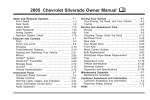
2004 Chevrolet Silverado Owner Manual
Seats and Restraint Systems ........................... 1-1
Front Seats ............................................... 1-3
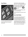
Rear Seats
............................................... 1-8
Safety Belts ............................................. 1-10
Child Restraints
....................................... 1-31
Air Bag Systems
...................................... 1-68
Restraint System Check
............................ 1-85
Features and Controls ..................................... 2-1
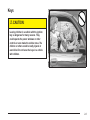
Keys
........................................................ 2-3
Doors and Locks
....................................... 2-7
Windows ................................................. 2-15
Theft-Deterrent Systems ............................ 2-18
Starting and Operating Your Vehicle
........... 2-20
Mirrors .................................................... 2-53
OnStar® System
...................................... 2-63
Storage Areas
......................................... 2-64
Vehicle Personalization
............................. 2-67
.............................................
3-1
Instrument Panel
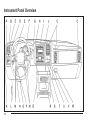
Instrument Panel Overview .......................... 3-4
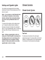
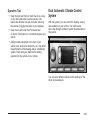
Climate Controls
...................................... 3-20
Warning Lights, Gages and Indicators
......... 3-33
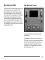
Driver Information Center (DIC)
.................. 3-54
Audio System(s) ....................................... 3-72
M
Driving Your Vehicle ....................................... 4-1
Your Driving, the Road, and Your Vehicle
..... 4-2
Towing
................................................... 4-53
Service and Appearance Care .......................... 5-1
Service ..................................................... 5-3
Fuel ......................................................... 5-4
Checking Things Under the Hood
............... 5-10
All-Wheel Drive
........................................ 5-57
Rear Axle
............................................... 5-58
Four-Wheel Drive
..................................... 5-58
Noise Control System
............................... 5-61
Bulb Replacement
.................................... 5-62
Windshield Wiper Blade Replacement
......... 5-72
Tires
...................................................... 5-73
Appearance Care
................................... 5-112
Vehicle Identification
............................... 5-121
Electrical System .................................... 5-121
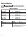
Capacities and Specifications
................... 5-130
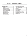
Maintenance Schedule ..................................... 6-1
Maintenance Schedule ................................ 6-2
Customer Assistance and Information .............. 7-1
Customer Assistance and Information
........... 7-2
Reporting Safety Defects ........................... 7-10
Index .................................................................1
Canadian Owners
You can obtain a French copy of this manual from your
dealer or from:
Helm, Incorporated
P.O. Box 07130
Detroit, MI 48207
GENERAL MOTORS, GM, the GM Emblem,
CHEVROLET, the CHEVROLET Emblem and the name
SILVERADO are registered trademarks of General
Motors Corporation.
This manual includes the latest information at the time it
was printed. We reserve the right to make changes
after that time without further notice. For vehicles first
sold in Canada, substitute the name “General Motors of
Canada Limited” for Chevrolet Motor Division whenever
it appears in this manual.
Please keep this manual in your vehicle, so it will be
there if you ever need it when you’re on the road. If you
sell the vehicle, please leave this manual in it so the
new owner can use it.
Litho in U.S.A.
Part No. C2415 A First Edition
ii
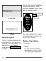
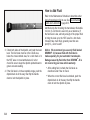
How to Use This Manual
Many people read their owner’s manual from beginning
to end when they first receive their new vehicle. If
you do this, it will help you learn about the features and
controls for your vehicle. In this manual, you will find
that pictures and words work together to explain things.
Index
A good place to look for what you need is the Index in
back of the manual. It is an alphabetical list of what
is in the manual, and the page number where you will
find it.
© Copyright General Motors Corporation 06/23/03
All Rights Reserved
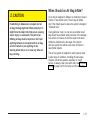
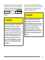
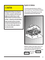
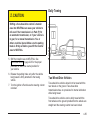
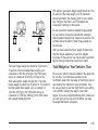
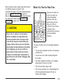
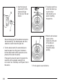
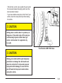
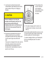
Safety Warnings and Symbols
You will find a number of safety cautions in this book.
We use a box and the word CAUTION to tell you about
things that could hurt you if you were to ignore the
warning.
You will also find a circle
with a slash through it in
this book. This safety
symbol means “Don’t,”
“Don’t do this” or “Don’t let
this happen.”
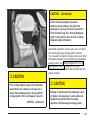
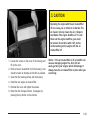
{CAUTION:
These mean there is something that could hurt
you or other people.
In the caution area, we tell you what the hazard is.
Then we tell you what to do to help avoid or reduce the
hazard. Please read these cautions. If you don’t, you
or others could be hurt.
iii
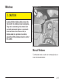
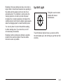
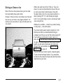
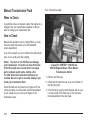
Vehicle Damage Warnings
Vehicle Symbols
Also, in this book you will find these notices:
Your vehicle has components and labels that use
symbols instead of text. Symbols, used on your vehicle,
are shown along with the text describing the operation
or information relating to a specific component, control,
message, gage or indicator.
Notice: These mean there is something that could
damage your vehicle.
A notice will tell you about something that can damage
your vehicle. Many times, this damage would not be
covered by your warranty, and it could be costly. But the
notice will tell you what to do to help avoid the
damage.
When you read other manuals, you might see
CAUTION and NOTICE warnings in different colors or in
different words.
You’ll also see warning labels on your vehicle. They use
the same words, CAUTION or NOTICE.
iv
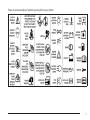
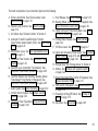
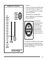
If you need help figuring out a specific name of a
component, gage or indicator, reference the following
topics:
•
•
•
•
•
•
•
Seats and Restraint Systems in Section 1
Features and Controls in Section 2
Instrument Panel Overview in Section 3
Climate Controls in Section 3
Warning Lights, Gages and Indicators in Section 3
Audio System(s) in Section 3
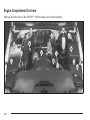
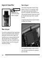
Engine Compartment Overview in Section 5
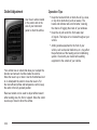
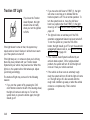
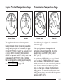
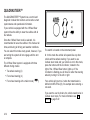
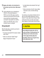
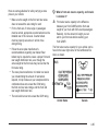
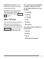
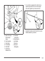
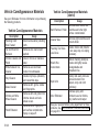
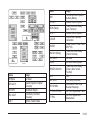
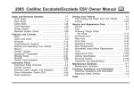
These are some examples of symbols you may find on your vehicle:
v
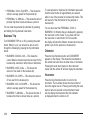
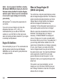
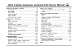
Model Reference
This manual covers these models:
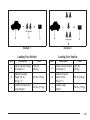
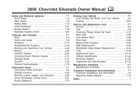
Regular Cab Pickup
vi
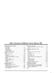
Extended Cab Pickup
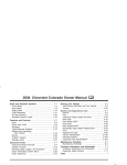
Crew Cab®
Chassis Cab
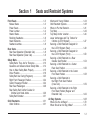
Section 1
Seats and Restraint Systems
Front Seats ......................................................1-3
Manual Seats ................................................1-3
Power Seats ..................................................1-4
Power Lumbar ...............................................1-4
Heated Seats .................................................1-5
Reclining Seatbacks ........................................1-6
Head Restraints .............................................1-7
Seatback Latches ...........................................1-8
Rear Seats .......................................................1-8
Rear Seat Operation (Extended Cab) ................1-8
Rear Seat Operation (Crew Cab) ......................1-9
Safety Belts ...................................................1-10
Safety Belts: They Are for Everyone ................1-10
Questions and Answers About Safety Belts ......1-14
How to Wear Safety Belts Properly .................1-15
Driver Position ..............................................1-16
Safety Belt Use During Pregnancy ..................1-23
Right Front Passenger Position .......................1-24
Center Passenger Position .............................1-24
Rear Seat Passengers ..................................1-26
Rear Safety Belt Comfort Guides for
Children and Small Adults ..........................1-29
Safety Belt Extender .....................................1-31
Child Restraints .............................................1-31
Older Children ..............................................1-31
Infants and Young Children ............................1-34
Child Restraint Systems .................................1-38
Where to Put the Restraint .............................1-41
Top Strap ....................................................1-42
Top Strap Anchor Location .............................1-44
Lower Anchorages and Top Tethers for
Children (LATCH System) ...........................1-47
Securing a Child Restraint Designed for
the LATCH System (Rear) ..........................1-49
Securing a Child Restraint Designed for
the LATCH System (Front) .........................1-50
Securing a Child Restraint in a Rear
Outside Seat Position ................................1-54
Securing a Child Restraint in a Center
Rear Seat Position ....................................1-56
Securing a Child Restraint in the Center
Front Seat Position ....................................1-58
Securing a Child Restraint in
the Right Front Seat Position
(Crew Cab) ..............................................1-59
Securing a Child Restraint in the Right
Front Seat Position (Regular and
Extended Cab) ..........................................1-62
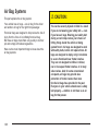
Air Bag Systems ............................................1-68
Where Are the Air Bags? ...............................1-70
When Should an Air Bag Inflate? ....................1-71
1-1
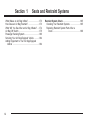
Section 1
Seats and Restraint Systems
What Makes an Air Bag Inflate? .....................1-73
How Does an Air Bag Restrain? .....................1-73
What Will You See After an Air Bag Inflates? ...1-74
Air Bag Off Switch ........................................1-75
Passenger Sensing System ............................1-80
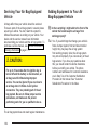
Servicing Your Air Bag-Equipped Vehicle .........1-84
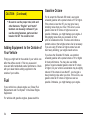
Adding Equipment to Your Air Bag-Equipped
Vehicle ....................................................1-84
1-2
Restraint System Check ..................................1-85
Checking Your Restraint Systems ...................1-85
Replacing Restraint System Parts After a
Crash ......................................................1-86
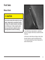
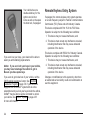
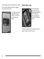
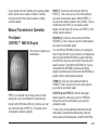
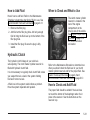
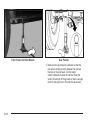
Front Seats
Manual Seats
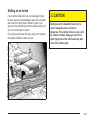
{CAUTION:
You can lose control of the vehicle if you try to
adjust a manual driver’s seat while the vehicle
is moving. The sudden movement could startle
and confuse you, or make you push a pedal
when you don’t want to. Adjust the driver’s
seat only when the vehicle is not moving.
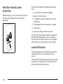
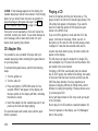
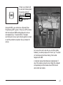
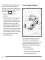
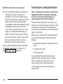
If your vehicle has a manual bucket or a split bench
seat, you can adjust it with this lever located at the front
of the seat.
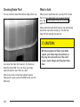
Lift the lever to unlock the seat. Using your body, slide
the seat to where you want it and release the lever.
Try to move the seat with your body to make sure the
seat is locked into place.
1-3
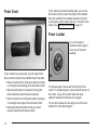
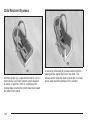
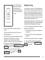
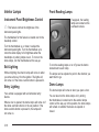
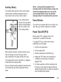
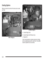
Power Seats
If your vehicle has power reclining seats, you can use
the vertical control to adjust the angle of the seatback.
Move the reclining front seatback rearward or forward
by moving the control toward the rear or the front of the
vehicle. See Reclining Seatbacks on page 1-6.
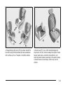
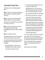
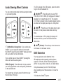
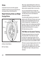
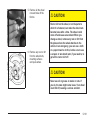
Power Lumbar
You can increase or
decrease lumbar support
in an area of the lower
seatback.
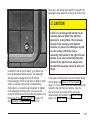
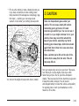
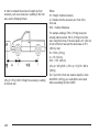
If your vehicle has a power seat, you can adjust it with
these controls located on the outboard sides of the seats.
• Raise or lower the front of the seat cushion by raising
or lowering the forward edge of the horizontal control.
• Move the seat forward or rearward by moving the
whole horizontal control forward or rearward.
• Raise or lower the rear of the seat cushion by raising
or lowering the rear edge of the horizontal control.
• Moving the whole horizontal control up or down
raises or lowers the entire seat cushion.
1-4
To increase support, press and hold the front of the
control. To decrease support, press and hold the rear of
the control. Let go of the control when the lower
seatback reaches the desired level of support.
You can also reshape the side wing area of the lower
seatback for more lateral support.
To increase support, press and hold the top of the
control. To decrease support, press and hold the bottom
of the control. Let go of the control when the lower
seatback reaches the desired level of support.
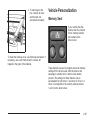
Your vehicle may have a memory function which allows
seat settings to be saved and recalled. See Memory
Seat on page 2-67 for more information.
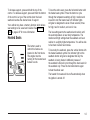
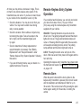
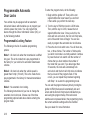
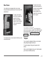
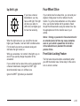
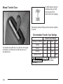
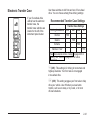
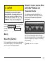
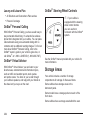
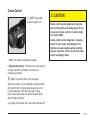
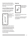
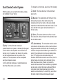
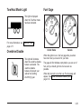
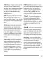
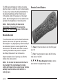
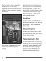
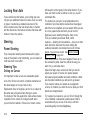
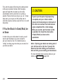
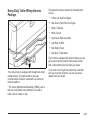
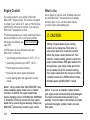
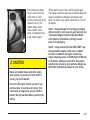
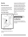
Heated Seats
The buttons used to
control this feature are
located on the front doors.
The engine must be
running for the heated seat
feature to work.
To heat the entire seat, press the horizontal button with
the heated seat symbol. Press the button to cycle
through the temperature settings of high, medium and
low and to turn the heated seat off. Indicator lights
will glow to designate the level of heat selected, three
for high, two for medium, and one for low.
The low setting warms the seatback and cushion until
the seat temperature is near body temperature. The
medium and high settings heat the seatback and seat
cushion to a slightly higher temperature. You will be able
to feel heat in about two minutes.
To heat only the seatback, press the vertical button with
the heated seatback symbol. An indicator light on the
seatback button will glow to designate that only the
seatback is being heated. Additional presses of
the seatback button will cycle through the heat levels for
the seatback only. Press the horizontal button again
to heat the whole seat.
The heated front seats will shut off automatically when
the ignition is turned off.
1-5
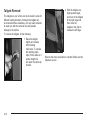
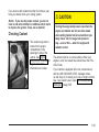
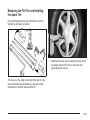
Reclining Seatbacks
To adjust the front seatback, lift the manual lever
located on the outboard side of the seat. Release the
lever to lock the seatback where you want it. Lift
the lever again without pushing on the seatback and the
seatback will go to an upright position.
If your vehicle has power seats with a power recliner,
see Power Seats on page 1-4 for further information on
how to operate the reclining seatback feature.
1-6
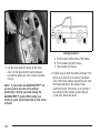
But don’t have a seatback reclined if your vehicle is
moving.
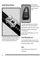
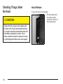
Head Restraints
{CAUTION:
Sitting in a reclined position when your vehicle
is in motion can be dangerous. Even if you
buckle up, your safety belts can’t do their job
when you’re reclined like this.
The shoulder belt can’t do its job. In a crash,
you could go into it, receiving neck or other
injuries.
The lap belt can’t do its job either. In a crash
the belt could go up over your abdomen. The
belt forces would be there, not at your pelvic
bones. This could cause serious internal
injuries.
For proper protection when the vehicle is in
motion, have the seatback upright. Then sit
well back in the seat and wear your safety belt
properly.
Adjust your head restraint so that the top of the restraint
is closest to the top of your head. This position
reduces the chance of a neck injury in a crash.
To raise the head restraint pull up on the head restraint.
On some models the head restraints tilt forward and
rearward also.
The rear seat head restraints in your vehicle may be
adjustable. They work the same as the front seat head
restraints, except they do not tilt forward and rearward.
1-7
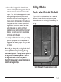
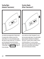
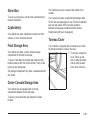
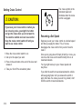
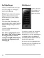
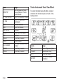
Seatback Latches
{CAUTION:
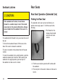
Rear Seats
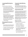
Rear Seat Operation (Extended Cab)
Folding the Rear Seat
If the seatback isn’t locked, it could move
forward in a sudden stop or crash. That could
cause injury to the person sitting there. Always
press rearward on the seatback to be sure it is
locked.
The seatbacks fold forward to let you access the rear of
the cab.
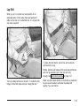
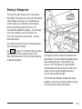
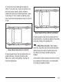
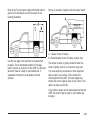
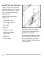
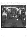
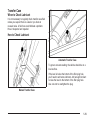
The extended cab’s rear seat can be folded up to
provide more cargo space. To fold the seat do the
following:
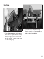
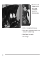
1. Pull forward on the
release strap located
under the rear seat
cushion.
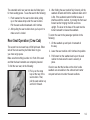
To fold a front seatback forward, lift the lever at the
base of the seat to release the seatback.
The lever is located on the outboard side of the seat
cushion.
To return the seatback to the upright position, push the
seatback rearward until it latches. After returning the
seatback to its upright position, push and pull on
the seatback to make sure it is locked.
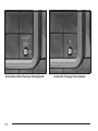
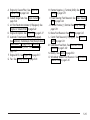
2. Fold the seat cushion upward until it latches with
the seatback.
3. Push and pull on the seat to make sure the seat is
secure.
1-8
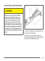
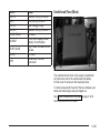
The extended cab’s rear seat can also be folded open
for more seating space. To use the seat do the following:
1. Push rearward on the seat cushion while pulling
up on the release strap under the seat cushion.
Pull the seat cushion downward until it latches.
2. After pulling the seat cushion down, pull up on it to
make sure it is locked.
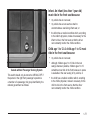
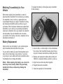
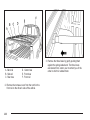
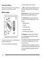
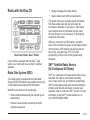
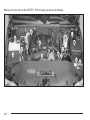
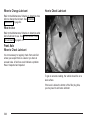
Rear Seat Operation (Crew Cab)
The second row rear seat has a 60/40 split seat. Either
side of the rear seat may be folded down to give
you more cargo space.
Make sure that nothing is under or in front of the seat
and that the head restraints are completely lowered.
To fold the rear seat, do the following:
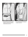
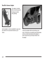
1. Pull up on the strap
loop at the rear of the
seat cushion. Then,
pull the seat cushion up
and fold it forward.
2. After folding the seat cushion fully forward, pull the
seatback forward and fold the seatback down until it
is flat. If the seatback cannot fold flat because it
interferes with the cushion, try moving the front seat
forward and/or bringing the front seat more
upright. The lever at the base of the seat must be
turned rearward to release the seatback.
To return the seat to the passenger position do the
following:
1. Lift the seatback up and push it rearward all
the way.
2. Lower the seat cushion until it latches into position.
3. Pull forward on the seatback and up on the seat
cushion to make sure the seat is securely in
place.
Check to see that the buckles on the driver’s side
seatback are accessible to the outboard and center
occupant and are not under the seat cushions.
1-9
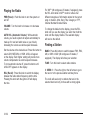
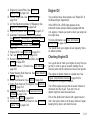
Safety Belts
{CAUTION:
Safety Belts: They Are for Everyone
This part of the manual tells you how to use safety
belts properly. It also tells you some things you should
not do with safety belts.
{CAUTION:
Don’t let anyone ride where he or she can’t
wear a safety belt properly. If you are in a
crash and you’re not wearing a safety belt,
your injuries can be much worse. You can hit
things inside the vehicle or be ejected from it.
You can be seriously injured or killed. In the
same crash, you might not be, if you are
buckled up. Always fasten your safety belt,
and check that your passengers’ belts are
fastened properly too.
It is extremely dangerous to ride in a cargo
area, inside or outside of a vehicle. In a
collision, people riding in these areas are more
likely to be seriously injured or killed. Do not
allow people to ride in any area of your vehicle
that is not equipped with seats and safety
belts. Be sure everyone in your vehicle is in a
seat and using a safety belt properly.
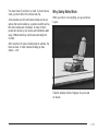
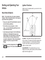
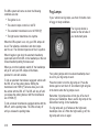
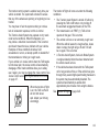
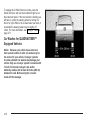
Your vehicle has a light
that comes on as a
reminder to buckle up. See
Safety Belt Reminder
Light on page 3-36.
In most states and in all Canadian provinces, the law
says to wear safety belts. Here’s why: They work.
1-10
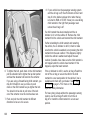
You never know if you’ll be in a crash. If you do have a
crash, you don’t know if it will be a bad one.
A few crashes are mild, and some crashes can be so
serious that even buckled up, a person wouldn’t survive.
But most crashes are in between. In many of them,
people who buckle up can survive and sometimes walk
away. Without belts they could have been badly hurt
or killed.
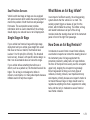
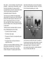
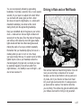
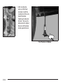
Why Safety Belts Work
When you ride in or on anything, you go as fast as
it goes.
After more than 30 years of safety belts in vehicles, the
facts are clear. In most crashes buckling up does
matter... a lot!
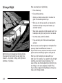
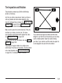
Take the simplest vehicle. Suppose it’s just a seat
on wheels.
1-11
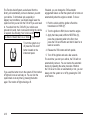
Put someone on it.
1-12
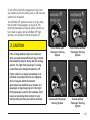
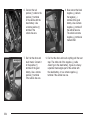
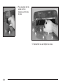
Get it up to speed. Then stop the vehicle. The rider
doesn’t stop.
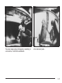
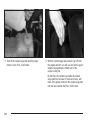
The person keeps going until stopped by something. In
a real vehicle, it could be the windshield...
or the instrument panel...
1-13
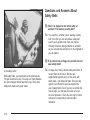
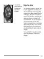
Questions and Answers About
Safety Belts
Q: Won’t I be trapped in the vehicle after an
accident if I’m wearing a safety belt?
A:
You could be – whether you’re wearing a safety
belt or not. But you can unbuckle a safety belt,
even if you’re upside down. And your chance
of being conscious during and after an accident,
so you can unbuckle and get out, is much greater if
you are belted.
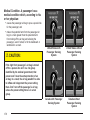
Q: If my vehicle has air bags, why should I have to
wear safety belts?
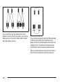
or the safety belts!
With safety belts, you slow down as the vehicle does.
You get more time to stop. You stop over more distance,
and your strongest bones take the forces. That’s why
safety belts make such good sense.
1-14
A:
Air bags are in many vehicles today and will be in
most of them in the future. But they are
supplemental systems only; so they work with
safety belts – not instead of them. Every air bag
system ever offered for sale has required the
use of safety belts. Even if you’re in a vehicle that
has air bags, you still have to buckle up to get
the most protection. That’s true not only in frontal
collisions, but especially in side and other
collisions.
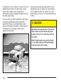
Q: If I’m a good driver, and I never drive far from
home, why should I wear safety belts?
A:
You may be an excellent driver, but if you’re in an
accident – even one that isn’t your fault – you and
your passengers can be hurt. Being a good
driver doesn’t protect you from things beyond your
control, such as bad drivers.
Most accidents occur within 25 miles (40 km) of
home. And the greatest number of serious injuries
and deaths occur at speeds of less than 40 mph
(65 km/h).
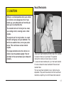
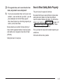
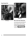
How to Wear Safety Belts Properly
This part is only for people of adult size.
Be aware that there are special things to know about
safety belts and children. And there are different
rules for smaller children and babies. If a child will be
riding in your vehicle, see Older Children on page 1-31
or Infants and Young Children on page 1-34. Follow
those rules for everyone’s protection.
First, you’ll want to know which restraint systems your
vehicle has.
We’ll start with the driver position.
Safety belts are for everyone.
1-15
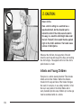
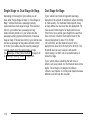
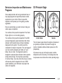
Driver Position
This part describes the driver’s restraint system.
Lap-Shoulder Belt
The driver has a lap-shoulder belt. Here’s how to wear it
properly.
1. Close and lock the door.
2. Adjust the seat so you can sit up straight. To see
how, see “Seats” in the Index.
1-16
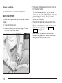
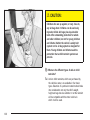
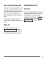
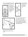
3. Pick up the latch plate and pull the belt across you.
Don’t let it get twisted.
The shoulder belt may lock if you pull the belt
across you very quickly. If this happens, let the belt
go back slightly to unlock it. Then pull the belt
across you more slowly.
4. Push the latch plate into the buckle until it clicks.
Pull up on the latch plate to make sure it is secure.
If the belt isn’t long enough, see Safety Belt
Extender on page 1-31.
Make sure the release button on the buckle is
positioned so you would be able to unbuckle the
safety belt quickly if you ever had to.
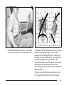
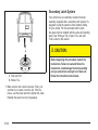
5. To make the lap part tight, pull down on the buckle
end of the belt as you pull up on the shoulder belt.
The lap part of the belt should be worn low and snug on
the hips, just touching the thighs. In a crash, this
applies force to the strong pelvic bones. And you’d be
less likely to slide under the lap belt. If you slid under it,
the belt would apply force at your abdomen. This
could cause serious or even fatal injuries. The shoulder
belt should go over the shoulder and across the
chest. These parts of the body are best able to take belt
restraining forces.
The safety belt locks if there’s a sudden stop or crash,
or if you pull the belt very quickly out of the retractor.
1-17
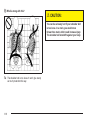
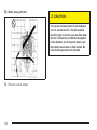
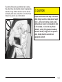
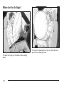
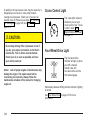
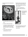
Q: What’s wrong with this?
{CAUTION:
You can be seriously hurt if your shoulder belt
is too loose. In a crash, you would move
forward too much, which could increase injury.
The shoulder belt should fit against your body.
A:
1-18
The shoulder belt is too loose. It won’t give nearly
as much protection this way.
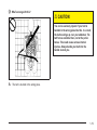
Q: What’s wrong with this?
{CAUTION:
You can be seriously injured if your belt is
buckled in the wrong place like this. In a crash,
the belt would go up over your abdomen. The
belt forces would be there, not at the pelvic
bones. This could cause serious internal
injuries. Always buckle your belt into the
buckle nearest you.
A:
The belt is buckled in the wrong place.
1-19
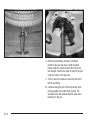
Q:
What’s wrong with this?
{CAUTION:
You can be seriously injured if your belt goes
over an armrest like this. The belt would be
much too high. In a crash, you can slide under
the belt. The belt force would then be applied
at the abdomen, not at the pelvic bones, and
that could cause serious or fatal injuries. Be
sure the belt goes under the armrests.
A:
1-20
The belt is over an armrest.
Q: What’s wrong with this?
{CAUTION:
You can be seriously injured if you wear the
shoulder belt under your arm. In a crash, your
body would move too far forward, which would
increase the chance of head and neck injury.
Also, the belt would apply too much force to
the ribs, which aren’t as strong as shoulder
bones. You could also severely injure internal
organs like your liver or spleen.
A:
The shoulder belt is worn under the arm. It should
be worn over the shoulder at all times.
1-21
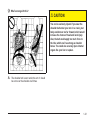
Q: What’s wrong with this?
{CAUTION:
You can be seriously injured by a twisted belt.
In a crash, you wouldn’t have the full width of
the belt to spread impact forces. If a belt is
twisted, make it straight so it can work
properly, or ask your dealer to fix it.
A:
1-22
The belt is twisted across the body.
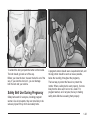
To unlatch the belt, just push the button on the buckle.
The belt should go back out of the way.
Before you close the door, be sure the belt is out of the
way. If you slam the door on it, you can damage
both the belt and your vehicle.
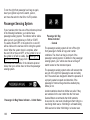
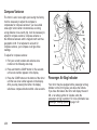
Safety Belt Use During Pregnancy
Safety belts work for everyone, including pregnant
women. Like all occupants, they are more likely to be
seriously injured if they don’t wear safety belts.
A pregnant woman should wear a lap-shoulder belt, and
the lap portion should be worn as low as possible,
below the rounding, throughout the pregnancy.
The best way to protect the fetus is to protect the
mother. When a safety belt is worn properly, it’s more
likely that the fetus won’t be hurt in a crash. For
pregnant women, as for anyone, the key to making
safety belts effective is wearing them properly.
1-23
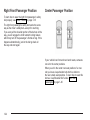
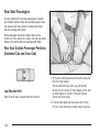
Right Front Passenger Position
Center Passenger Position
To learn how to wear the right front passenger’s safety
belt properly, see Driver Position on page 1-16.
The right front passenger’s safety belt works the same
way as the driver’s safety belt—except for one thing.
If you ever pull the shoulder portion of the belt out all the
way, you will engage the child restraint locking feature
which may turn off the passenger’s frontal air bag. If this
happens unintentionally, just let the belt go back all
the way and start again.
If your vehicle has front and rear bench seats, someone
can sit in the center positions.
When you sit in the center rear seat position of a crew
cab you have a lap-shoulder belt which is similar to
the rear outside seat positions. To learn how to wear this
belt see “Lap-Shoulder Belt” under Rear Seat
Passengers on page 1-26.
1-24
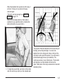
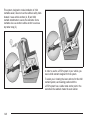
Lap Belt
When you sit in a center rear seat position of an
extended cab or in the center front seat position of
either a crew cab or an extended cab, or a regular cab,
you have a lap belt.
To make the belt shorter, pull its free end as shown
until the belt is snug.
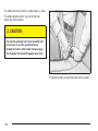
Buckle, position and release it the same way as the lap
part of a lap-shoulder belt. If the belt isn’t long
enough, see Safety Belt Extender on page 1-31.
Your lap safety belt has no retractor. To make the belt
longer, tilt the latch plate and pull it along the belt.
Make sure the release button on the buckle is positioned
so you would be able to unbuckle the safety belt
quickly if you ever had to.
1-25
Rear Seat Passengers
It’s very important for rear seat passengers to buckle
up! Accident statistics show that unbelted people in the
rear seat are hurt more often in crashes than those
who are wearing safety belts.
Rear passengers who aren’t safety belted can be
thrown out of the vehicle in a crash. And they can strike
others in the vehicle who are wearing safety belts.
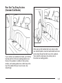
Rear Seat Outside Passenger Positions
(Extended Cab and Crew Cab)
Lap-Shoulder Belt
Here’s how to wear a lap-shoulder belt properly.
1. Pick up the latch plate and pull the belt across you.
Don’t let it get twisted.
The shoulder belt may lock if you pull the belt
across you very quickly. If this happens, let the belt
go back slightly to unlock it. Then pull the belt
across you more slowly.
2. Push the latch plate into the buckle until it clicks.
Pull up on the latch plate to make sure it is secure.
1-26
When the shoulder belt is pulled out all the way, it
will lock. If it does, let it go back all the way
and start again.
If the belt is not long enough, see Safety Belt
Extender on page 1-31.
Make sure the release button on the buckle is
positioned so you would be able to unbuckle the
safety belt quickly if you ever had to.
The lap part of the belt should be worn low and snug on
the hips, just touching the thighs. In a crash, this
applies force to the strong pelvic bones. And you’d be
less likely to slide under the lap belt. If you slid under it,
the belt would apply force at your abdomen. This
could cause serious or even fatal injuries. The shoulder
belt should go over the shoulder and across the
chest. These parts of the body are best able to take belt
restraining forces.
3. To make the lap part tight, pull down on the buckle
end of the belt as you pull up on the shoulder part.
1-27
The safety belt locks if there’s a sudden stop or a crash.
The safety belt also locks if you pull the belt very
quickly out of the retractor.
{CAUTION:
You can be seriously hurt if your shoulder belt
is too loose. In a crash, you would move
forward too much, which could increase injury.
The shoulder belt should fit against your body.
To unlatch the belt, just push the button on the buckle.
1-28
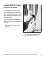
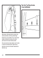
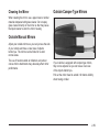
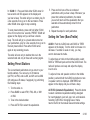
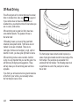
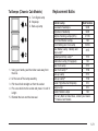
Rear Safety Belt Comfort Guides for
Children and Small Adults
Rear seat comfort guides provide added safety belt
comfort for older children who have outgrown booster
seats and for small adults. When installed on a shoulder
belt, the comfort guide better positions the belt away
from the neck and head.
There is one guide for each outside passenger in the
rear seat. Here’s how to install a comfort guide and use
the safety belt:
1. Remove the guide from its storage clip on the
interior body.
2. Place the guide over the belt and insert the two
edges of the belt into the slots of the guide.
1-29
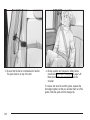
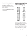
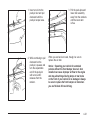
3. Be sure that the belt is not twisted and it lies flat.
The guide must be on top of the belt.
4. Buckle, position and release the safety belt as
described in Rear Seat Passengers on page 1-26.
Make sure that the shoulder belt crosses the
shoulder.
To remove and store the comfort guides, squeeze the
belt edges together so that you can take them out of the
guides. Slide the guide onto the storage clip.
1-30
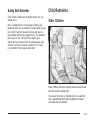
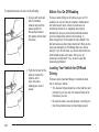
Safety Belt Extender
Child Restraints
If the vehicle’s safety belt will fasten around you, you
should use it.
Older Children
But if a safety belt isn’t long enough to fasten, your
dealer will order you an extender. It’s free. When you go
in to order it, take the heaviest coat you will wear, so
the extender will be long enough for you. The extender
will be just for you, and just for the seat in your
vehicle that you choose. Don’t let someone else use it,
and use it only for the seat it is made to fit. To wear
it, just attach it to the regular safety belt.
Older children who have outgrown booster seats should
wear the vehicle’s safety belts.
If you have the choice, a child should sit in a seat that
has a lap-shoulder belt to get the additional restraint
a shoulder belt can provide.
1-31
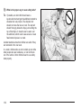
Q:
A:
What is the proper way to wear safety belts?
If possible, an older child should wear a
lap-shoulder belt and get the additional restraint a
shoulder belt can provide. The shoulder belt
should not cross the face or neck. The lap belt
should fit snugly below the hips, just touching the
top of the thighs. It should never be worn over
the abdomen, which could cause severe or even
fatal internal injuries in a crash.
Accident statistics show that children are safer if they
are restrained in the rear seat.
In a crash, children who are not buckled up can strike
other people who are buckled up, or can be thrown
out of the vehicle. Older children need to use safety
belts properly.
1-32
Q:
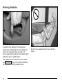
{CAUTION:
Never do this.
Here two children are wearing the same belt.
The belt can’t properly spread the impact
forces. In a crash, the two children can be
crushed together and seriously injured. A belt
must be used by only one person at a time.
A:
What if a child is wearing a lap-shoulder belt,
but the child is so small that the shoulder belt
is very close to the child’s face or neck?
If the child is sitting in a rear outside seat position,
move the child toward the center of the vehicle.
See Rear Safety Belt Comfort Guides for Children
and Small Adults on page 1-29. If the child is
sitting in the center rear seat position of a crew
cab, move the child toward the safety belt buckle.
In either case be sure that the shoulder belt
still is on the child’s shoulder, so that in a crash
the child’s upper body would have the restraint that
belts provide.
If the child is so small that the shoulder belt is still
very close to the child’s face or neck, you might
want to place the child a seat that has a lap belt, if
your vehicle has one.
1-33
{CAUTION:
Never do this.
Here a child is sitting in a seat that has a
lap-shoulder belt, but the shoulder part is
behind the child. If the child wears the belt in
this way, in a crash the child might slide under
the belt. The belt’s force would then be applied
right on the child’s abdomen. That could cause
serious or fatal injuries.
Wherever the child sits, the lap portion of the belt
should be worn low and snug on the hips, just touching
the child’s thighs. This applies belt force to the child’s
pelvic bones in a crash.
Infants and Young Children
Everyone in a vehicle needs protection! This includes
infants and all other children. Neither the distance
traveled nor the age and size of the traveler changes
the need, for everyone, to use safety restraints. In fact,
the law in every state in the United States and in
every Canadian province says children up to some age
must be restrained while in a vehicle.
1-34
Every time infants and young children ride in vehicles,
they should have the protection provided by appropriate
restraints. Young children should not use the vehicle’s
adult safety belts alone, unless there is no other choice.
Instead, they need to use a child restraint.
{CAUTION:
People should never hold a baby in their arms
while riding in a vehicle. A baby doesn’t weigh
much -- until a crash. During a crash a baby
will become so heavy it is not possible to hold
it. For example, in a crash at only 25 mph
(40 km/h), a 12-lb. (5.5 kg) baby will suddenly
become a 240-lb. (110 kg) force on a person’s
arms. A baby should be secured in an
appropriate restraint.
1-35
{CAUTION:
Children who are up against, or very close to,
any air bag when it inflates can be seriously
injured or killed. Air bags plus lap-shoulder
belts offer outstanding protection for adults
and older children, but not for young children
and infants. Neither the vehicle’s safety belt
system nor its air bag system is designed for
them. Young children and infants need the
protection that a child restraint system can
provide.
Q: What are the different types of add-on child
restraints?
A:
1-36
Add-on child restraints, which are purchased by
the vehicle’s owner, are available in four basic
types. Selection of a particular restraint should take
into consideration not only the child’s weight,
height and age but also whether or not the restraint
will be compatible with the motor vehicle in
which it will be used.
For most basic types of child restraints, there are
many different models available. When purchasing a
child restraint, be sure it is designed to be used
in a motor vehicle. If it is, the restraint will have a
label saying that it meets federal motor vehicle
safety standards.
The restraint manufacturer’s instructions that come
with the restraint state the weight and height
limitations for a particular child restraint. In addition,
there are many kinds of restraints available for
children with special needs.
{CAUTION:
Newborn infants need complete support,
including support for the head and neck. This
is necessary because a newborn infant’s neck
is weak and its head weighs so much
compared with the rest of its body. In a crash,
an infant in a rear-facing seat settles into the
restraint, so the crash forces can be
distributed across the strongest part of an
infant’s body, the back and shoulders. Infants
always should be secured in appropriate infant
restraints.
{CAUTION:
The body structure of a young child is quite
unlike that of an adult or older child, for whom
the safety belts are designed. A young child’s
hip bones are still so small that the vehicle’s
regular safety belt may not remain low on the
hip bones, as it should. Instead, it may settle
up around the child’s abdomen. In a crash, the
belt would apply force on a body area that’s
unprotected by any bony structure. This alone
could cause serious or fatal injuries. Young
children always should be secured in
appropriate child restraints.
1-37
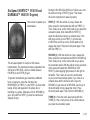
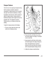
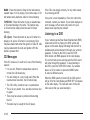
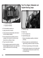
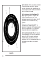
Child Restraint Systems
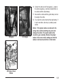
An infant car bed (A), a special bed made for use in a
motor vehicle, is an infant restraint system designed
to restrain or position a child on a continuous flat
surface. Make sure that the infant’s head rests toward
the center of the vehicle.
1-38
A rear-facing infant seat (B) provides restraint with the
seating surface against the back of the infant. The
harness system holds the infant in place and, in a crash,
acts to keep the infant positioned in the restraint.
A forward-facing child seat (C-E) provides restraint for
the child’s body with the harness and also sometimes
with surfaces such as T-shaped or shelf-like shields.
A booster seat (F-G) is a child restraint designed to
improve the fit of the vehicle’s safety belt system. Some
booster seats have a shoulder belt positioner, and
some high-back booster seats have a five-point harness.
A booster seat can also help a child to see out the
window.
1-39
Q: How do child restraints work?
A: A child restraint system is any device designed for
use in a motor vehicle to restrain, seat, or position
children. A built-in child restraint system is a
permanent part of the motor vehicle. An add-on
child restraint system is a portable one, which
is purchased by the vehicle’s owner.
For many years, add-on child restraints have used
the adult belt system in the vehicle. To help
reduce the chance of injury, the child also has to be
secured within the restraint. The vehicle’s belt
system secures the add-on child restraint in the
vehicle, and the add-on child restraint’s harness
system holds the child in place within the restraint.
One system, the three-point harness, has straps that
come down over each of the infant’s shoulders and
buckle together at the crotch. The five-point harness
system has two shoulder straps, two hip straps and a
crotch strap. A shield may take the place of hip
straps. A T-shaped shield has shoulder straps that
are attached to a flat pad which rests low against the
child’s body. A shelf- or armrest-type shield has
straps that are attached to a wide, shelf-like shield
that swings up or to the side.
1-40
When choosing a child restraint, be sure the child
restraint is designed to be used in a vehicle. If it is, it
will have a label saying that it meets federal motor
vehicle safety standards.
Then follow the instructions for the restraint. You may
find these instructions on the restraint itself or in a
booklet, or both. These restraints use the belt system or
the LATCH system in your vehicle, but the child also
has to be secured within the restraint to help reduce the
chance of personal injury. When securing an add-on
child restraint, refer to the instructions that come with the
restraint which may be on the restraint itself or in a
booklet, or both, and to this manual. The child restraint
instructions are important, so if they are not available,
obtain a replacement copy from the manufacturer.
Where to Put the Restraint
Accident statistics show that children are safer if they
are restrained in the rear rather than the front seat.
General Motors recommends that child restraints
be secured in a rear seat including an infant riding in a
rear-facing infant seat, a child riding in a forward-facing
child seat and an older child riding in a booster seat.
Never put a child in a rear-facing child restraint in
the right front passenger seat unless your vehicle has
the passenger sensing system and/or an air bag
off switch and the air bag status indicator shows off.
Never put a rear facing child restraint in the right front
passenger seat unless the air bag is off. Here is why:
{CAUTION:
A child in a rear-facing child restraint can be
seriously injured or killed if the right front
passenger’s air bag inflates. This is because the
back of the rear-facing child restraint would be
very close to the inflating air bag. Be sure the air
bag is off before using a rear-facing child
restraint in the right front seat position.
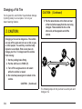
CAUTION:
CAUTION:
(Continued)
Even though the passenger sensing system
and/or air bag off switch are designed to turn
off the passenger’s frontal air bag under
certain conditions, no system is fail-safe, and
no one can guarantee that an air bag will not
deploy under some unusual circumstance,
even though it is turned off. General Motors
recommends that rear-facing child restraints
be transported in vehicles with a rear seat that
will accommodate a rear-facing child restraint,
whenever possible.
If you secure a forward-facing child restraint in
the right front seat, always move the front
passenger seat as far back as it will go. It is
better to secure the child restraint in a rear seat.
Do not use child restraints in the center front seat
position. The restraints will not work properly.
(Continued)
1-41
There is limited space in the rear seating area of an
extended cab model. If you need to secure a child
restraint in a rear seating position of an extended cab
model, especially in the rear center position, be
sure to study the instructions that came with your child
restraint to see if there is enough room to secure
your seat properly.
If your vehicle has the passenger sensing system
and/or the air bag off switch and you need to secure a
rear-facing child restraint in the right front passenger’s
seat, the passenger’s frontal air bag must be off.
See Passenger Sensing System on page 1-80, Securing
a Child Restraint in the Right Front Seat Position
(Regular and Extended Cab) on page 1-62, Securing a
Child Restraint Designed for the LATCH System
(Rear) on page 1-49 or Securing a Child Restraint
Designed for the LATCH System (Front) on page 1-50,
and Air Bag Off Switch on page 1-75 for more on
this including important safety information.
Wherever you install it, be sure to secure the child
restraint properly.
Keep in mind that an unsecured child restraint can
move around in a collision or sudden stop and injure
people in the vehicle. Be sure to properly secure
any child restraint in your vehicle – even when no child
is in it.
1-42
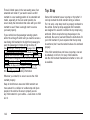
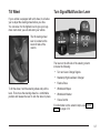
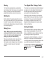
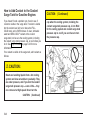
Top Strap
Some child restraints have a top strap or 'top tether'. It
can help restrain the child restraint during a collision.
For it to work, a top strap much be properly anchored to
the vehicle. Some top strap-equipped child restraints
are designed for use with or without the top strap being
anchored. Others require the top strap always to be
anchored. Be sure to read and follow the instructions for
your child restraint. If yours requires that the top strap
be anchored, don’t use the restraint unless it is anchored
properly.
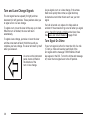
If the child restraint does not have a top strap, one can
be obtained, in kit form, for many child restraints.
Ask the child restraint manufacturer whether or not a kit
is available.
In Canada, the law requires that forward-facing child
restraints have a top strap, and that the strap be
anchored. In the United States, some child restraints
also have a top strap. If your child restraint has a
top strap, it should be anchored.
Anchor the top strap to one of the following anchor
points. Be sure to use an anchor point located on the
same side of the vehicle as the seating position
where the child restraint will be placed. Raise the head
restraint and route the top strap under it.
Once you have the top strap anchored, you’ll be ready
to secure the child restraint itself. Tighten the top
strap when and as the child restraint manufacturer’s
instructions say.
1-43
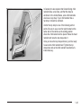
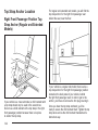
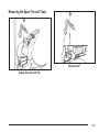
Top Strap Anchor Location
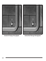
Right Front Passenger Position Top
Strap Anchor (Regular and Extended
Models)
If your vehicle is a crew cab model, a child restraint with
a top strap should only be used in the second row.
Do not use a child restraint with a top strap in the right
front passenger position because there is no place
to anchor the top strap.
1-44
For regular and extended cab models, you will find the
top strap anchor for the right front passenger seat
behind the seat, near the floor.
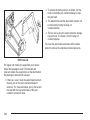
If your vehicle is a regular cab model, there is also a
top strap anchor for the right front passenger position
located on the back panel of your vehicle, behind
the right front passenger seat. In order to get to the
anchor, you’ll have to remove the trim plug covering it.
Once you have the top strap anchored, you’ll be
ready to secure the child restraint itself. Tighten the top
strap when and as the child restraint manufacturer’s
instructions say.
Rear Seat Top Strap Anchors
(Extended Cab Models)
If your vehicle is an extended cab model, you’ll find the
top strap anchors for the rear seating positions near
the top of the seatback. In addition to the top strap
anchors, each seating position has a fabric loop at the
top of the seatback that you’ll use to route a top
strap through.
When using a child restraint with a top strap in either
rear outboard position, raise the head restraint and route
the top strap through the fabric loop on the seatback.
Then, attach the top strap to the anchor point at
the center rear seating position.
1-45
Rear Seat Top Strap Anchors
(Crew Cab Models)
When using a child restraint with a top strap in the
center rear position, route the top strap through
the fabric loop on the seatback. Then, raise the head
restraint and attach the top strap to the anchor
point located at the closest outboard position.
Once you have the top strap anchored, you’ll be ready
to secure the child restrain itself. Tighten the top
strap when and as the child restraint manufacturer’s
instructions say.
1-46
If your vehicle is a Crew Cab model, you’ll find top strap
anchors for the rear seating positions located on the
back panel of your vehicle, behind the rear seat.
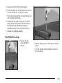
Lower Anchorages and Top Tethers
for Children (LATCH System)
In order to get to the brackets, you’ll have to remove the
trim plugs covering them.
There are also anchorage points at the rear base of the
front passenger’s seat.
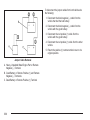
Your vehicle has the LATCH system. You will find
anchors (A) for the front passenger and the center rear
seating positions for extended cab models. For
regular cab models, you will find anchors for the right
front passenger seating position. For crew cab models,
you will find anchors for the second row center and
second row right passenger seating positions.
1-47
This system, designed to make installation of child
restraints easier, does not use the vehicle’s safety belts.
Instead, it uses vehicle anchors (A, B) and child
restraint attachments to secure the restraints. Some
restraints also use another vehicle anchor to secure a
top tether strap (C).
In order to use the LATCH system in your vehicle, you
need a child restraint designed for that system.
To assist you in locating the lower anchors for this child
restraint system, each seating position with the
LATCH system has a visible metal anchor point in the
seat where the seatback meets the seat cushion.
1-48
{CAUTION:
If a LATCH-type child restraint is not attached
to its anchorage points, the restraint will not
be able to protect the child correctly. In a
crash, the child could be seriously injured or
killed. Make sure that a LATCH-type child
restraint is properly installed using the
anchorage points, or use the vehicle’s safety
belts to secure the restraint, following the
instructions that came with that restraint, and
also the instructions in this manual.
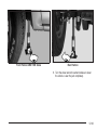
Securing a Child Restraint Designed
for the LATCH System (Rear)
1. Find the LATCH anchorages for the seating
position you want to use, where the bottom of the
seatback meets the back of the seat cushion.
2. Put the child restraint on the seat.
3. Attach and tighten the LATCH attachments on the
child restraint to the LATCH anchorages in the
vehicle. The child restraint instructions will show
you how.
4. If the child restraint is forward-facing, attach and
tighten the top tether to the top tether anchorage.
The child restraint instructions will show you
how. Also see Top Strap on page 1-42.
5. Push and pull the child restraint in different
directions to be sure it is secure.
To remove the child restraint, simply unhook the top
tether from the top tether anchorage and then
disconnect the LATCH attachments from the LATCH
anchorages.
1-49
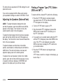
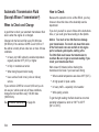
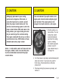
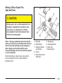
Securing a Child Restraint Designed
for the LATCH System (Front)
Your vehicle has a right front passenger air bag. There
is a switch on the instrument panel that you can use
to turn off the right front passenger’s frontal air bag. See
the following illustration. Your switch may vary slightly.
See Air Bag Off Switch on page 1-75 for more on
this, including important safety information and
illustrations of alternate switch designs.
{CAUTION:
A child in a rear-facing child restraint can be
seriously injured or killed if the right front
passenger’s air bag inflates. This is because
the back of the rear facing child restraint
CAUTION:
1-50
(Continued)
CAUTION:
(Continued)
would be very close to the inflating air bag. Be
sure the air bag is off before using a
rear-facing child restraint in the right front seat
position.
Even though the passenger sensing system
and/or air bag off switch are designed to turn
off the passenger’s frontal air bag under
certain conditions, no system is fail-safe, and
no one can guarantee that an air bag will not
deploy under some unusual circumstance,
even though it is turned off. General Motors
recommends that rear-facing child restraints
be transported in vehicles with a rear seat that
will accommodate a rear-facing child restraint,
whenever possible.
Never put a rear facing child restraint in the right front
passenger’s seat unless the air bag is off. Here is why:
{CAUTION:
In addition to the air bag off switch, your vehicle may
have the passenger sensing system. The passenger
sensing system is designed to turn off the right
front passenger’s frontal air bag when an infant or small
child in a rear-facing infant seat, a forward-facing
child restraint, or a booster seat is detected. In addition
to the passenger sensing system, you may use the
air bag off switch located on the instrument panel to turn
the air bag off. See Air Bag Off Switch on page 1-75
and Passenger Sensing System on page 1-80.
A child in a rear-facing child restraint can be
seriously injured or killed if the right front
passenger’s air bag inflates. This is because
the back of the rear-facing child restraint
would be very close to the inflating air bag. Be
sure the air bag is off before using a
rear-facing child restraint in the right front seat
position. If you secure a forward-facing child
restraint in the right front seat, always move
the right front passenger seat as far back as it
will go.
A rear seat is a safer place to secure a forward facing
child restraint. See Where to Put the Restraint on
page 1-41. If you need to secure a forward-facing child
restraint in the right front seat position, move the
seat as far back as it will go before securing a
forward-facing child restraint. See Manual Seats on
page 1-3 or Power Seats on page 1-4.
1-51
{CAUTION:
If the air bag readiness light in the instrument
panel cluster ever comes on when you have
turned off the air bag, it means that something
may be wrong with the air bag system. The
right front passenger’s air bag could inflate
even though the switch is off. If this ever
happens, have the vehicle serviced promptly.
Until you have the vehicle serviced, do not let
anyone whom the national government has
identified as a member of a passenger air bag
risk group sit in the right front passenger’s
position (for example, do not secure a
rear-facing child restraint in the right front
passenger’s seat). See ″Air Bag Off Switch″ in
the Index.
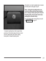
1. Your vehicle has a right front passenger’s frontal air
bag. See Air Bag Off Switch on page 1-75 and
Passenger Sensing System on page 1-80. If your
child restraint is forward-facing, move the seat as far
back as it will go before securing the restraint in
1-52
this seat. See Manual Seats on page 1-3 or Power
Seats on page 1-4. If you need to use a rear-facing
child restraint in this seat, make sure the air bag
is off once the child restraint has been installed.
When the passenger sensing system or the air bag
off switch has turned off the right front passenger’s
frontal air bag, the off indicator in the passenger
air bag status indicator should light and stay lit when
you turn the ignition to RUN or START. See
Passenger Air Bag Status Indicator on page 3-40.
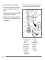
2. Find the LATCH anchorages where the bottom of
the seatback meets the back of the cushion.
3. Put the child restraint on the seat.
4. Attach and tighten the LATCH attachments on the
child restraint to the LATCH anchorages in the
vehicle. The child restraint instructions will show you
how.
5. If the child restraint is forward-facing, attach and
tighten the top tether to the top tether anchorage.
The child restraint instructions will show you
how. Also see Top Strap on page 1-42.
6. Push and pull the child restraint in different
directions to be sure it is secure.
7. If your vehicle has the passenger sensing system
and the air bag is off, the off indicator will be lit and
stay lit in the inside rearview mirror when the key
is turned to RUN or START. Never put a rear-facing
child restraint in the right front passenger seat
unless the air bag is off.
If a child restraint has been installed and the on
indicator is lit, turn the vehicle off. Remove the child
restraint from the vehicle and reinstall the restraint.
If after reinstalling the child restraint and restarting the
vehicle, the on indicator is still lit, check to make
sure that the vehicle’s seatback is not pressing the child
restraint into the seat cushion. If this happens, slightly
recline the vehicle’s seatback and adjust the seat
cushion if possible. Also make sure the child restraint is
not trapped under the vehicle head restraint. If this
happens, adjust the head restraint.
If the on indicator is still lit, use the air bag off switch to
turn off the air bag or secure the child in the child
restraint in a rear seat position in the vehicle if one is
available and check with your dealer. See Air Bag
Off Switch on page 1-75 for more on this, including
important safety information.
{CAUTION:
If the air bag ON indicator comes on when you
have a rear-facing child restraint installed in
the right front passenger’s seat, it means that
the passenger sensing system has not turned
off the passenger’s frontal air bag. A child in a
rear-facing child restraint can be seriously
injured or killed if the right front passenger’s
air bag inflates. This is because the back of
the rear-facing child restraint would be very
close to the inflating air bag. Don’t use a
rear-facing child restraint in the right front
passenger’s seat unless the air bag is off.
To remove the child restraint, unhook the top tether
from the top tether anchorage and then disconnect the
LATCH attachments from LATCH anchorages.
For heavy duty pickups without the passenger sensing
system, use the air bag off switch to turn the air
bag off or install the infant restraint in a rear seat
position.
1-53
If you had turned the air bag off with the switch,
remember to be sure to use the air bag off switch to
turn on the right front passenger’s air bag when
you remove the child restraint from the vehicle unless
the person who will be sitting there is a member of
a passenger air bag risk group. See Air Bag Off Switch
on page 1-75.
{CAUTION:
If the right front passenger’s air bag is turned
off for a person who isn’t in a risk group
identified by the national government, that
person won’t have the extra protection of an
air bag. In a crash, the air bag wouldn’t be able
to inflate and help protect the person sitting
there. Don’t turn off the passenger’s air bag
unless the person sitting there is in a risk
group. See ″Air Bag Off Switch″ in the Index
for more on this, including important safety
information.
Securing a Child Restraint in a Rear
Outside Seat Position
Extended Cab and Crew Cab
There is limited space in the rear seating of an extended
cab model. If you want to secure a child restraint in a
rear outside seating position, be sure to study the
instructions that came with your child restraint to see if
there is enough room to secure your seat properly.
If your child restraint is equipped with the LATCH
system, see Lower Anchorages and Top Tethers for
Children (LATCH System) on page 1-47. See Top Strap
on page 1-42 if the child restraint has one.
If your child restraint does not have the LATCH system,
you’ll be using the lap-shoulder belt to secure the child
restraint in this position. Be sure to follow the instructions
that came with the child restraint. Secure the child in the
child restraint when and as the instructions say.
1. Put the restraint on the seat.
1-54
2. Pick up the latch plate and run the lap and shoulder
portions of the vehicle’s safety belt through or
around the restraint. The child restraint instructions
will show you how.
4. Pull the rest of the shoulder belt all the way out of
the retractor to set the lock.
3. Buckle the belt. Make sure the release button is
positioned so you would be able to unbuckle the
safety belt quickly if you ever had to.
1-55
Securing a Child Restraint in a
Center Rear Seat Position
If you have a extended cab or crew cab pickup, you can
secure a child restraint in the center rear seat position.
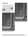
5. To tighten the belt, feed the shoulder belt back into the
retractor while you push down on the child restraint. If
you’re using a forward-facing child restraint, you
may find it helpful to use your knee to push down on
the child restraint as you tighten the belt.
6. Push and pull the restraint in different directions to
be sure it is secure.
To remove the child restraint, just unbuckle the vehicle’s
safety belt and let it go back all the way. The safety
belt will move freely again and be ready to work for an
adult or larger child passenger.
1-56
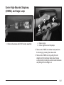
Crew Cab
When you secure a child restraint in the center rear
seat position of a crew cab, you’ll be using a
lap-shoulder belt that works the same way as the safety
belts in the rear outside seat positions. For instructions
on how to secure a child restraint using a lap-shoulder
belt see Securing a Child Restraint in a Rear Outside
Seat Position on page 1-54.
Extended Cab
There is limited space in the rear seating area of an
extended cab model. If you want to secure a child
restraint in a rear seat position of an extended cab
model, especially in the rear center seat position,
be sure to study the instructions that came with your
child restraint to see if there is enough room to secure
your child restraint properly.
If your child restraint is equipped with the LATCH
system, see Lower Anchorages and Top Tethers for
Children (LATCH System) on page 1-47. See Top Strap
on page 1-42 if the child restraint has one.
If your child restraint does not have the LATCH system,
you’ll be using the lap belt to secure a child restraint
in the center rear seat position of an extended cab. Be
sure to follow the instructions that came with the
child restraint. Secure the child in the child restraint
when and as the instructions say.
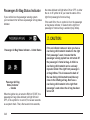
1. Make the belt as long as possible by tilting the latch
plate and pulling it along the belt.
2. Put the restraint on the seat.
1-57
5. To tighten the belt, pull its free end while you push
down on the child restraint. If you’re using a
forward-facing child restraint, you may find it helpful
to use your knee to push the child restraint as
you tighten the belt.
6. Push and pull the child restraint in different
directions to be sure it is secure.
To remove the child restraint, just unbuckle the vehicle’s
safety belt. It will be ready to work for an adult or
larger child passenger.
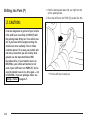
Securing a Child Restraint in the
Center Front Seat Position
3. Run the vehicle’s safety belt through or around the
restraint. The child restraint instructions will show
you how.
4. Buckle the belt. Make sure the release button is
positioned so you would be able to unbuckle the
safety belt quickly if you ever had to.
Don’t use child restraints in this position. The restraints
won’t work properly.
1-58
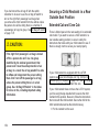
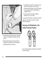
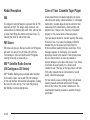
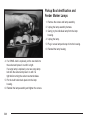
Securing a Child Restraint in
the Right Front Seat Position
(Crew Cab)
A rear seat is a safer place to secure a forward-facing
child restraint. If you need to secure a forward-facing
child restraint in the right front seat position, see Where
to Put the Restraint on page 1-41.
If your child restraint is equipped with the LATCH
system, see Lower Anchorages and Top Tethers for
Children (LATCH System) on page 1-47. See Top Strap
on page 1-42 if your child restraint has one.
You’ll be using the lap-shoulder belt to secure the
restraint in this position. Be sure to follow the
instructions that came with the child restraint. Secure
the child in the child restraint when and as the
instructions say.
Your vehicle has a right front passenger air bag. Never
put a rear-facing child restraint in the right front
passenger’s seat. Here’s why:
{CAUTION:
A child in a rear-facing child restraint can be
seriously injured or killed if the right front
passenger’s air bag inflates. This is because
the back of the rear-facing child restraint
would be very close to the inflating air bag.
Always secure a rear-facing child restraint in a
rear seat.
1. Because your vehicle has a right front passenger’s
frontal air bag, always move the seat as far back as
it will go before securing a forward-facing child
restraint. See Manual Seats on page 1-3 or Power
Seats on page 1-4.
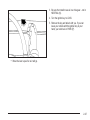
2. Put the restraint on the seat.
3. Pick up the latch plate, and run the lap and shoulder
portions of the vehicle’s safety belt through or
around the restraint. The child restraint instructions
will show you how.
1-59
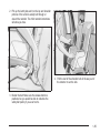
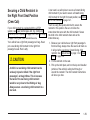
4. Buckle the belt. Make sure the release button is
positioned so you would be able to unbuckle the
safety belt quickly if you ever had to.
1-60
5. Pull the rest of the shoulder belt all the way out of
the retractor to set the lock.
6. To tighten the belt, feed the shoulder belt back into
the retractor while you push down on the child
restraint. If you’re using a forward-facing child
restraint, you may find it helpful to use your knee to
push down on the child restraint as you tighten the
belt. You should not be able to pull more of the belt
out of the retractor once the lock has been set.
7. Push and pull the child restraint in different
directions to be sure it is secure.
To remove the child restraint, just unbuckle the vehicle’s
safety belt and let it go back all the way. The safety
belt will move freely again and be ready to work for an
adult or larger child passenger.
1-61
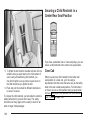
Securing a Child Restraint in the
Right Front Seat Position (Regular
and Extended Cab)
Your vehicle has a right front passenger air bag. There
is a switch on the instrument panel that you can use
to turn off the right front passenger’s frontal air bag. See
the following illustration. Your switch may vary slightly.
See Air Bag Off Switch on page 1-75 for more on
this, including important safety information and
illustrations of alternate switch designs.
{CAUTION:
A child in a rear-facing child restraint can be
seriously injured or killed if the right front
passenger’s air bag inflates. This is because
the back of the rear facing child restraint
would be very close to the inflating air bag. Be
sure the air bag is off before using a
rear-facing child restraint in the right front seat
position.
Even though the passenger sensing system
and/or air bag off switch are designed to turn
off the passenger’s frontal air bag under
certain conditions, no system is fail-safe, and
no one can guarantee that an air bag will not
deploy under some unusual circumstance,
even though it is turned off. General Motors
recommends that rear-facing child restraints
be transported in vehicles with a rear seat that
will accommodate a rear-facing child restraint,
whenever possible.
1-62
Never put a rear facing child restraint in the right front
passenger’s seat unless the air bag is off. Here is why:
{CAUTION:
In addition to the air bag off switch, your vehicle may
have the passenger sensing system. The passenger
sensing system is designed to turn off the right
front passenger’s frontal air bag when an infant or small
child in a rear-facing infant seat, a forward-facing
child restraint, or a booster seat is detected. In addition
to the passenger sensing system, you may use the
air bag off switch located on the instrument panel to turn
the air bag off. See Air Bag Off Switch on page 1-75
and Passenger Sensing System on page 1-80.
A child in a rear-facing child restraint can be
seriously injured or killed if the right front
passenger’s air bag inflates. This is because
the back of the rear-facing child restraint
would be very close to the inflating air bag. Be
sure the air bag is off before using a
rear-facing child restraint in the right front seat
position. If you secure a forward-facing child
restraint in the right front seat, always move
the right front passenger seat as far back as it
will go.
A rear seat is a safer place to secure a forward facing
child restraint. See Where to Put the Restraint on
page 1-41. If you need to secure a forward-facing child
restraint in the right front seat position, move the
seat as far back as it will go before securing a
forward-facing child restraint. See Manual Seats on
page 1-3 or Power Seats on page 1-4.
1-63
{CAUTION:
If the air bag readiness light in the instrument
panel cluster ever comes on when you have
turned off the air bag, it means that something
may be wrong with the air bag system. The
right front passenger’s air bag could inflate
even though the switch is off. If this ever
happens, have the vehicle serviced promptly.
Until you have the vehicle serviced, do not let
anyone whom the national government has
identified as a member of a passenger air bag
risk group sit in the right front passenger’s
position (for example, do not secure a
rear-facing child restraint in the right front
passenger’s seat). See ″Air Bag Off Switch″ in
the Index.
If your child restraint is equipped with the LATCH
system, see Lower Anchorages and Top Tethers for
Children (LATCH System) on page 1-47. See Top Strap
on page 1-42 if your child restraint has one.
1-64
If your child restraint does not have the LATCH system,
you will be using the lap-shoulder belt to secure the
child restraint in this position. Be sure to follow the
instructions that came with the child restraint. Secure
the child in the child restraint when and as the
instructions say.
1. Your vehicle has a right front passenger’s frontal air
bag. See Air Bag Off Switch on page 1-75 and
Passenger Sensing System on page 1-80. If your
child restraint is forward-facing, move the seat as far
back as it will go before securing the restraint in
this seat. See Manual Seats on page 1-3 or Power
Seats on page 1-4. If you need to use a rear-facing
child restraint in this seat, make sure the air bag
is off once the child restraint has been installed.
When the passenger sensing system or the air bag
off switch has turned off the right front passenger’s
frontal air bag, the off indicator in the passenger
air bag status indicator should light and stay lit when
you turn the ignition to RUN or START. See
Passenger Air Bag Status Indicator on page 3-40.
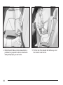
2. Put the child restraint on the seat.
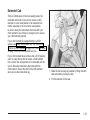
3. Pick up the latch plate, and run the lap and shoulder
portions of the vehicle’s safety belt through or
around the restraint. The child restraint instructions
will show you how.
4. Buckle the belt. Make sure the release button is
positioned so you would be able to unbuckle the
safety belt quickly if you ever had to.
5. Pull the rest of the shoulder belt all the way out of
the retractor to set the lock.
1-65
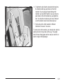
8. If your vehicle has the passenger sensing system
and the air bag is off, the off indicator will be lit and
stay lit in the inside rearview mirror when the key
is turned to RUN or START. Never put a rear-facing
child restraint in the right front passenger seat
unless the air bag is off.
If a child restraint has been installed and the on
indicator is lit, turn the vehicle off. Remove the child
restraint from the vehicle and reinstall the child restraint.
If after reinstalling the child restraint and restarting
the vehicle, the on indicator is still lit, check to make
sure that the vehicle’s seatback is not pressing the child
restraint into the seat cushion. If this happens, slightly
recline the vehicle’s seatback and adjust the seat
cushion if possible. Also make sure the child restraint is
not trapped under the vehicle head restraint. If this
happens, adjust the head restraint.
6. To tighten the belt, push down on the child restraint,
pull the shoulder belt to tighten the lap belt portion
and feed the shoulder belt back into the retractor.
If you are using a forward-facing child restraint, you
may find it helpful to use your knee to push
down on the child restraint as you tighten the belt.
You should not be able to pull more of the belt
out of the retractor once the lock has been set.
7. Push and pull the child restraint in different
directions to be sure it is secure.
1-66
If the on indicator is still lit, use the air bag off switch to
turn off the air bag or secure the child in the child
restraint in a rear seat position in the vehicle if one is
available and check with your dealer. See Air Bag
Off Switch on page 1-75 for more on this, including
important safety information.
For heavy duty pickups without the passenger sensing
system, use the air bag off switch to turn the air
bag off or install the infant restraint in a rear seat
position.
{CAUTION:
If the air bag ON indicator comes on when you
have a rear-facing child restraint installed in
the right front passenger’s seat, it means that
the passenger sensing system has not turned
off the passenger’s frontal air bag. A child in a
rear-facing child restraint can be seriously
injured or killed if the right front passenger’s
air bag inflates. This is because the back of
the rear-facing child restraint would be very
close to the inflating air bag. Don’t use a
rear-facing child restraint in the right front
passenger’s seat unless the air bag is off.
To remove the child restraint, just unbuckle the vehicle’s
safety belt and let it go back all the way. The safety
belt will move freely again and be ready to work for an
adult or larger child passenger.
If you had turned the air bag off with the switch,
remember to be sure to use the air bag off switch to
turn on the right front passenger’s air bag when
you remove the child restraint from the vehicle unless
the person who will be sitting there is a member of
a passenger air bag risk group. See Air Bag Off Switch
on page 1-75.
{CAUTION:
If the right front passenger’s air bag is turned
off for a person who isn’t in a risk group
identified by the national government, that
person won’t have the extra protection of an
air bag. In a crash, the air bag wouldn’t be able
to inflate and help protect the person sitting
there. Don’t turn off the passenger’s air bag
unless the person sitting there is in a risk
group. See ″Air Bag Off Switch″ in the Index
for more on this, including important safety
information.
1-67
Air Bag Systems
This part explains the air bag system.
Your vehicle has air bags – one air bag for the driver
and another air bag for the right front passenger.
Frontal air bags are designed to help reduce the risk of
injury from the force of an inflating frontal air bag.
But these air bags must inflate very quickly to do their
job and comply with federal regulations.
Here are the most important things to know about the
air bag systems:
1-68
{CAUTION:
You can be severely injured or killed in a crash
if you are not wearing your safety belt — even
if you have air bags. Wearing your safety belt
during a crash helps reduce your chance of
hitting things inside the vehicle or being
ejected from it. Air bags are designed to work
with safety belts, but do not replace them. Air
bags are designed to deploy only in moderate
to severe frontal and near frontal crashes.
They are not designed to inflate in rollover,
rear or low-speed frontal crashes, or in many
side crashes. And, for some unrestrained
occupants, air bags may provide less
protection in frontal crashes than more
forceful air bags have provided in the past.
Everyone in your vehicle should wear a safety
belt properly — whether or not there is an air
bag for that person.
CAUTION:
{CAUTION:
Air bags inflate with great force, faster than the
blink of an eye. If you’re too close to an
inflating air bag, as you would be if you were
leaning forward, it could seriously injure you.
Safety belts help keep you in position before
and during a crash. Always wear your safety
belt, even with air bags. The driver should sit
as far back as possible while still maintaining
control of the vehicle.
(Continued)
not for young children and infants. Neither the
vehicle’s safety belt system nor its air bag
system is designed for them. Young children
and infants need the protection that a child
restraint system can provide. Always secure
children properly in your vehicle. To read how,
see Older Children on page 1-31 and Infants
and Young Children on page 1-34.
There is an air bag
readiness light on the
instrument panel cluster,
which shows the air
bag symbol.
{CAUTION:
Anyone who is up against, or very close to,
any air bag when it inflates can be seriously
injured or killed. Air bags plus lap-shoulder
belts offer the best protection for adults, but
CAUTION:
(Continued)
The system checks the air bag electrical system for
malfunctions. The light tells you if there is an electrical
problem. See Air Bag Readiness Light on page 3-36
for more information.
1-69
Where Are the Air Bags?
The right front passenger’s air bag is in the instrument
panel on the passenger’s side.
The driver’s air bag is in the middle of the steering
wheel.
1-70
When Should an Air Bag Inflate?
{CAUTION:
If something is between an occupant and an
air bag, the bag might not inflate properly or it
might force the object into that person causing
severe injury or even death. The path of an
inflating air bag must be kept clear. Don’t put
anything between an occupant and an air bag,
and don’t attach or put anything on the
steering wheel hub or on or near any other air
bag covering.
An air bag is designed to inflate in a moderate to severe
frontal, or near-frontal crash. The air bag will inflate
only if the impact speed is above the system’s designed
“threshold level.”
In any particular crash, no one can say whether an air
bag should have inflated simply because of the damage
to a vehicle or because of what the repair costs were.
Inflation is determined by the angle of the impact
and how quickly the vehicle slows down in frontal or
near-frontal impacts.
The air bag system is designed to work properly under
a wide range of conditions, including off-road usage.
Observe safe driving speeds, especially on rough
terrain. As always, wear your safety belt. See Off-Road
Driving on page 4-20 for more tips on off-road driving.
1-71
Single Stage vs. Dual Stage Air Bags
Dual Stage Air Bags
Depending on the weight of your vehicle you will
have either “Single Stage Air Bags” or “Dual Stage Air
Bags”. Vehicles that have a passenger sensing
system also have dual stage air bags. If the rearview
mirror in your vehicle has a passenger air bag
status indicator printed on it, your vehicle has the
passenger sensing system and therefore, it has dual
stage air bags. If the rearview mirror in your vehicle does
not have a passenger air bag status indicator printed
on it, then your vehicle does not have the passenger
sensing system and it has single stage air bags.
See Passenger Air Bag Status Indicator on page 3-40
or Passenger Sensing System on page 1-80.
If your vehicle has frontal air bags with dual stage
deployment, the amount of restraint will adjust according
to crash severity. For moderate frontal impacts, these
air bags inflate at a level less than full deployment. For
more severe frontal impacts, full deployment occurs.
If the front of your vehicle goes straight into a wall that
does not move or deform, the threshold level for the
reduced deployment is about 10 to 16 mph
(16 to 25 km/h), and the threshold level for a full
deployment is about 20 to 25 mph (32 to 40 km/h). The
threshold level can vary, however, with specific
vehicle design, so that it can be somewhat above or
below this range.
If your vehicle strikes something that will move or
deform, such as a parked car, the threshold level will be
higher. The air bag is not designed to inflate in
rollovers, rear impacts, or in many side impacts because
inflation would not help the occupant.
1-72
Seat Position Sensors
What Makes an Air Bag Inflate?
Vehicle’s with dual stage air bags are also equipped
with special sensors which enable the sensing system to
monitor the position of both the driver and passenger
front seats. The seat position sensor provides
information which is used to determine if the air bags
should deploy at a reduced level or at full deployment.
In an impact of sufficient severity, the air bag sensing
system detects that the vehicle is in a crash. The
sensing system triggers a release of gas from the
inflator, which inflates the air bag. The inflator, air bag,
and related hardware are all part of the air bag
modules inside the steering wheel and in the instrument
panel in front of the right front passenger.
Single Stage Air Bags
If your vehicle has frontal air bags with single stage
deployment and your vehicle goes straight into a wall
that does not move or deform, the threshold level
is about 13 to 16 mph (20 to 25 km/h). The threshold
level can vary, however, with specific vehicle design, so
that it can be somewhat above or below this range.
If your vehicle strikes something that will move or
deform, such as a parked car, the threshold level will be
higher. The air bag is not designed to inflate in
rollovers, rear impacts, or in many side impacts because
inflation would not help the occupant.
How Does an Air Bag Restrain?
In moderate to severe frontal or near-frontal collisions,
even belted occupants can contact the steering wheel or
the instrument panel. Air bags supplement the
protection provided by safety belts. Air bags distribute
the force of the impact more evenly over the occupant’s
upper body, stopping the occupant more gradually.
But air bags would not help you in many types of
collisions, including rollovers, rear impacts and many
side impacts, primarily because an occupant’s motion is
not toward those air bags. Air bags should never be
regarded as anything more than a supplement to safety
belts, and then only in moderate to severe frontal or
near-frontal collisions.
1-73
What Will You See After an Air Bag
Inflates?
After an air bag inflates, it quickly deflates, so quickly
that some people may not even realize the air bag
inflated. Some components of the air bag module – the
steering wheel hub for the driver’s air bag, or the
instrument panel for the right front passenger’s
bag – will be hot for a short time. The parts of the bag
that come into contact with you may be warm, but
not too hot to touch. There will be some smoke and dust
coming from the vents in the deflated air bags. Air
bag inflation does not prevent the driver from seeing or
being able to steer the vehicle, nor does it stop
people from leaving the vehicle.
(Continued)
the vehicle should get out as soon as it is safe
to do so. If you have breathing problems but
can’t get out of the vehicle after an air bag
inflates, then get fresh air by opening a
window or a door. If you experience breathing
problems following an air bag deployment, you
should seek medical attention.
In many crashes severe enough to inflate the air bag,
windshields are broken by vehicle deformation.
Additional windshield breakage may also occur from the
right front passenger air bag.
• Air bags are designed to inflate only once. After
{CAUTION:
When an air bag inflates, there is dust in the
air. This dust could cause breathing problems
for people with a history of asthma or other
breathing trouble. To avoid this, everyone in
CAUTION:
1-74
CAUTION:
(Continued)
they inflate, you will need some new parts for
your air bag system. If you do not get them, the air
bag system will not be there to help protect you
in another crash. A new system will include air bag
modules and possibly other parts. The service
manual for your vehicle covers the need to replace
other parts.
• Your vehicle is equipped with electronic frontal
sensors which help the sensing system distinguish
between a moderate and a more severe frontal
impact. Your vehicle is also equipped with a crash
sensing and diagnostic module, which records
information about the frontal air bag system. The
module records information about the readiness of
the system and when the system commands air
bag inflation. It records the status of the driver’s
safety belt usage in a crash in which the air
bag deploys or a crash in which the air bag nearly
deploys. The module also records speed, engine
rpm, brake and throttle data.
Air Bag Off Switch
Regular Cab and Extended Cab Models
If your vehicle is a regular cab model or an extended
cab model, it has a switch on the instrument panel
that you can use to turn off the right front passenger’s
air bag.
• Let only qualified technicians work on your air bag
systems. Improper service can mean that an air
bag system will not work properly. See your dealer
for service.
Notice: If you damage the covering for the driver’s
or the right front passenger’s air bag, the bag
may not work properly. You may have to replace the
air bag module in the steering wheel or both the
air bag module and the instrument panel for
the right front passenger’s air bag. Do not open or
break the air bag coverings.
United States with Passenger Sensing System
1-75
United States without Passenger Sensing System
1-76
Canada with Passenger Sensing System
Infant. An infant (less than 1 year old)
must ride in the front seat because:
• my vehicle has no rear seat;
• my vehicle has a rear seat too small to
accommodate a rear-facing infant seat; or
• the infant has a medical condition which, according
to the infant’s physician, makes it necessary for the
infant to ride in the front seat so that the driver
can constantly monitor the child’s condition.
Child age 1 to 12. A child age 1 to 12 must
ride in the front seat because:
• my vehicle has no rear seat;
• although children ages 1 to 12 ride in the rear
Canada without Passenger Sensing System
This switch should only be turned to AIR BAG OFF if
the person in the right front passenger’s position is
a member of a passenger risk group identified by the
national government as follows:
seat(s) whenever possible, children ages 1 to 12
sometimes must ride in the front because no space
is available in the rear seat(s) of my vehicle; or
• the child has a medical condition which, according
to the child’s physician, makes it necessary for the
child to ride in the front seat so that the driver
can constantly monitor the child’s condition.
1-77
Medical Condition. A passenger has a
medical condition which, according to his
or her physician:
• causes the passenger air bag to pose a special risk
for the passenger; and
• makes the potential harm from the passenger air
bag in a crash greater than the potential harm
from turning off the air bag and allowing the
passenger, even if belted, to hit the dashboard or
windshield in a crash.
{CAUTION:
United States with
Passenger Sensing
System
United States without
Passenger Sensing
System
Canada with Passenger
Sensing System
Canada without
Passenger Sensing
System
If the right front passenger’s air bag is turned
off for a person who isn’t in a risk group
identified by the national government, that
person won’t have the extra protection of an
air bag. In a crash, the air bag wouldn’t be able
to inflate and help protect the person sitting
there. Don’t turn off the passenger’s air bag
unless the person sitting there is in a risk
group.
1-78
To turn off the right front passenger’s air bag, insert
your ignition key into the switch, push in, and move the
switch to the off position.
The AIR BAG OFF light will come on to let you know
that the right front passenger’s air bag is off. The
right front passenger’s air bag will remain off until you
turn it back on again, and the AIR BAG OFF light
will stay on to remind you that the air bag is off.
{CAUTION:
If the air bag readiness light ever comes on
when you have turned off the air bag, it means
that something may be wrong with the air bag
system. The right front passenger’s air bag
could inflate even though the switch is off.
If your vehicle is a regular cab pickup or an
extended cab pickup and this ever happens,
don’t let anyone whom the national
government has identified as a member of a
passenger air bag risk group sit in the right
front passenger’s position (for example, don’t
secure a rear-facing child restraint in your
vehicle) until you have your vehicle serviced.
United States with
Passenger Sensing
System
United States without
Passenger Sensing
System
Canada with Passenger
Sensing System
Canada without
Passenger Sensing
System
1-79
To turn the right front passenger’s air bag on again,
insert your ignition key into the switch, push in,
and move the switch to the ON or AUTO position.
Passenger Sensing System
If your rearview mirror has one of the indicators pictured
in the following illustrations, your vehicle has a
passenger sensing system. The indicator will be visible
when you turn your ignition key to RUN or START.
The words ON and OFF or the symbol for on and off,
will be visible on the rearview mirror during the system
check. When the system check is complete, either
the word ON or the word OFF, or the symbol for on or
the symbol for off will be visible. See Passenger Air
Bag Status Indicator on page 3-40. If your rearview
mirror does not have either of the indicators pictured
below, then your vehicle does not have the passenger
sensing system.
Passenger Air Bag Status Indicator – United States
1-80
Passenger Air Bag
Status Indicator
− Canada
The passenger sensing system will turn off the right
front passenger’s frontal air bag under certain
conditions. The driver’s air bag is not part of the
passenger sensing system. In addition to the passenger
sensing system, your vehicle also has an air bag off
switch located on the instrument panel.
The passenger sensing system works with sensors that
are part of the right front passenger’s seat and safety
belt. The sensors are designed to detect the presence of
a properly seated occupant and determine if the
passenger’s frontal air bag should be enabled (may
inflate) or not.
Accident statistics show that children are safer if they
are restrained in the rear rather than the front seat.
General Motors recommends that child restraints
be secured in a rear seat, including an infant riding in a
rear-facing infant seat, a child riding in a forward-facing
child seat and an older child riding in a booster seat.
Never put a child in a rear-facing child restraint in the
right front passenger seat unless the passenger air bag
status indicator shows off. Never put a rear-facing
child restraint in the right front passenger seat unless
the air bag is off.
{CAUTION:
A child in a rear-facing child restraint can be
seriously injured or killed if the right front
passenger’s air bag inflates. This is because
the back of the rear-facing child restraint
would be very close to the inflating air bag. Be
sure the air bag is off before using a
rear-facing child restraint in the right front seat
position.
Even though the passenger sensing system is
designed to turn off the passenger’s frontal air
bag if the system detects a rear-facing child
restraint, no system is fail-safe, and no one
can guarantee that an air bag will not deploy
CAUTION:
(Continued)
CAUTION:
(Continued)
under some unusual circumstance, even
though it is turned off. General Motors
recommends that rear-facing child restraints
be secured in a rear seat whenever possible,
even if the air bag is off.
The passenger sensing system is designed to turn off
the right front passenger’s frontal air bag if:
• the right front passenger seat is unoccupied
• the system determines that an infant is present in a
rear-facing infant seat
• the system determines that a small child is present
in a forward-facing child restraint
• the system determines that a small child is present
in a booster seat
• a right front passenger takes his/her weight off of
the seat for a period of time
• the right front passenger seat is occupied by a
smaller person, such as a child who has outgrown
child restraints
• the air bag off switch is in the off position
• or if there is a critical problem with the air bag
system or the passenger sensing system
1-81
When the passenger’s frontal air bag has been turned
off either by the passenger sensing system or by the air
bag off switch, the off indicator will light and stay lit to
remind you that the air bag is off.
If a child restraint has been installed and the on
indicator is lit, turn the vehicle off. Remove the child
restraint from the vehicle and reinstall the child restraint
following the child restraint manufacturer’s directions
and refer to Securing a Child Restraint in the Right Front
Seat Position (Regular and Extended Cab) on
page 1-62 or Securing a Child Restraint Designed for
the LATCH System (Front) on page 1-50.
If after reinstalling the child restraint and restarting the
vehicle, the on indicator is still lit, check to make
sure that the vehicle’s seatback is not pressing the child
restraint into the seat cushion. If this happens, slightly
recline the vehicle’s seatback and adjust the seat
cushion if possible. Also make sure the child restraint is
not trapped under the vehicle head restraint. If this
happens, adjust the head restraint.
If the on indicator is still lit, use the air bag off switch to
turn off the air bag or secure the child in the child
restraint in a rear seat position in the vehicle if one is
available and check with your dealer. See Air Bag
Off Switch on page 1-75 for more on this, including
important safety information.
1-82
The passenger sensing system is designed to enable
(may inflate) the right front passenger’s frontal air
bag anytime the system senses that a person of adult
size is sitting properly in the right front passenger’s seat.
When the passenger sensing system has allowed the
air bag to be enabled, the on indicator will light and stay
lit to remind you that the air bag is active.
For some children who have outgrown child restraints
and for very small adults, the passenger sensing system
may or may not turn off the right front passenger’s
frontal air bag, depending upon the person’s seating
posture and body build. Everyone in your vehicle
who has outgrown child restraints should wear a safety
belt properly — whether or not there is an air bag
for that person.
If a person of adult-size is sitting in the right front
passenger’s seat, but the off indicator is lit, it could be
because that person is not sitting properly in the seat or
the air bag off switch is in the off position. If this
happens and the switch is in the proper position, turn
the vehicle off and ask the person to place the seatback
in the fully upright position, then sit upright in the
seat, centered on the seat cushion, with the person’s
legs comfortably extended. Restart the vehicle and have
the person remain in this position for about two
minutes. This will allow the system to detect that person
and then enable the passenger’s air bag.
CAUTION:
(Continued)
vehicle serviced promptly, because an
adult-size person sitting in the right front
passenger’s seat may not have the protection
of the frontal air bag. See “Air Bag Readiness
Light” in the Index for more on this, including
important safety information.
Aftermarket equipment, such as seat covers, can affect
how well the passenger sensing system operates.
You may want to consider not using seat covers or other
aftermarket equipment if your vehicle has the passenger
sensing system. See Adding Equipment to Your Air
Bag-Equipped Vehicle on page 1-84 for more
information about modifications that can affect how the
system operates.
{CAUTION:
If the air bag readiness light in the instrument
panel cluster ever comes on and stays on, it
means that something may be wrong with the
air bag system. If this ever happens, have the
CAUTION:
(Continued)
{CAUTION:
Stowing of articles under the passenger’s seat
or between the passenger’s seat cushion and
seatback may interfere with the proper
operation of the passenger sensing system.
1-83
Servicing Your Air Bag-Equipped
Vehicle
Air bags affect how your vehicle should be serviced.
There are parts of the air bag system in several places
around your vehicle. You don’t want the system to
inflate while someone is working on your vehicle. Your
dealer and the service manual have information
about servicing your vehicle and the air bag system. To
purchase a service manual, see Service Publications
Ordering Information on page 7-11.
{CAUTION:
For up to 10 seconds after the ignition key is
turned off and the battery is disconnected, an
air bag can still inflate during improper
service. You can be injured if you are close to
an air bag when it inflates. Avoid yellow
connectors. They are probably part of the air
bag system. Be sure to follow proper service
procedures, and make sure the person
performing work for you is qualified to do so.
The air bag system does not need regular maintenance.
1-84
Adding Equipment to Your Air
Bag-Equipped Vehicle
Q: Is there anything I might add to the front of the
vehicle that could keep the air bags from
working properly?
A:
Yes. If you add things that change your vehicle’s
frame, bumper system, front end sheet metal or
height, they may keep the air bag system
from working properly. Also, the air bag system
may not work properly if you relocate any of the air
bag sensors. If you have any questions about
this, you should contact Customer Assistance
before you modify your vehicle. The phone
numbers and addresses for Customer Assistance
are in Step Two of the Customer Satisfaction
Procedure in this manual. See ″Customer
Satisfaction Procedure″ in the Index.
Q: What if I added a snow plow? Will it keep the
air bags from working properly?
A:
We’ve designed our air bag systems to
work properly under a wide range of conditions,
including snow plowing with vehicles equipped
with the optional Snow Plow Prep Package
(RPO VYU). But don’t change or defeat the snow
plow’s ″tripping mechanism.″ If you do, it can
damage your snow plow and your vehicle, and it
may cause an air bag inflation.
Q: Because I have a disability, I have to get my
vehicle modified. How can I find out whether
this will affect my advanced air bag sysgem?
A:
Changing or moving any parts of the front seats,
safety belts, the air bag sensing and diagnostic
module (located under the driver’s seat), or
the inside rearview mirror can affect the operation
of the advanced air bag system. If you have
questions, call Customer Assistance. The phone
numbers and addresses for Customer Assistance
are in Step Two of the Customer Satisfaction
Procedure in this Manual. See Customer
Satisfaction Procedure on page 7-2.
Restraint System Check
Checking Your Restraint Systems
Now and then, make sure the safety belt reminder light
and all your belts, buckles, latch plates, retractors
and anchorages are working properly. Look for any other
loose or damaged safety belt system parts. If you see
anything that might keep a safety belt system from doing
its job, have it repaired.
Torn or frayed safety belts may not protect you in a
crash. They can rip apart under impact forces. If a belt
is torn or frayed, get a new one right away.
Also look for any opened or broken air bag covers, and
have them repaired or replaced. (The air bag system
does not need regular maintenance.)
1-85
Replacing Restraint System Parts
After a Crash
{CAUTION:
A crash can damage the restraint systems in
your vehicle. A damaged restraint system may
not properly protect the person using it,
resulting in serious injury or even death in a
crash. To help make sure your restraint
systems are working properly after a crash,
have them inspected and any necessary
replacements made as soon as possible.
1-86
If you’ve had a crash, do you need new belts or LATCH
system parts?
After a very minor collision, nothing may be necessary.
But if the belts were stretched, as they would be if
worn during a more severe crash, then you need
new parts.
If the LATCH system was being used during a more
severe crash, you may need new LATCH system parts.
If belts are cut or damaged, replace them. Collision
damage also may mean you will need to have LATCH
system, safety belt or seat parts repaired or replaced.
New parts and repairs may be necessary even if the belt
or LATCH system wasn’t being used at the time of
the collision.
If an air bag inflates, you’ll need to replace air bag
system parts. See the part on the air bag system earlier
in this section.
Section 2
Features and Controls
Keys ...............................................................2-3
Remote Keyless Entry System .........................2-4
Remote Keyless Entry System Operation ...........2-5
Doors and Locks .............................................2-7
Door Locks ....................................................2-7
Power Door Locks ..........................................2-8
Delayed Locking .............................................2-9
Programmable Automatic Door Locks ..............2-10
Rear Door Security Locks (Crew Cab) .............2-12
Lockout Protection ........................................2-12
Rear Doors ..................................................2-13
Tailgate .......................................................2-13
Windows ........................................................2-15
Manual Windows ..........................................2-15
Power Windows ............................................2-16
Swing-Out Windows ......................................2-17
Sun Visors ...................................................2-17
Theft-Deterrent Systems ..................................2-18
Content Theft-Deterrent .................................2-18
Passlock® ....................................................2-19
Starting and Operating Your Vehicle ................2-20
New Vehicle Break-In ....................................2-20
Ignition Positions ..........................................2-20
Starting Your Engine .....................................2-22
Engine Coolant Heater ..................................2-24
Automatic Transmission Operation ...................2-25
Manual Transmission Operation ......................2-29
Four-Wheel Drive ..........................................2-33
All-Wheel Drive ............................................2-44
Parking Brake ..............................................2-44
Shifting Into Park (P) .....................................2-46
Shifting Out of Park (P) .................................2-49
Parking Your Vehicle .....................................2-49
Parking Over Things That Burn .......................2-50
Engine Exhaust ............................................2-51
Running Your Engine While You Are Parked ....2-52
Mirrors ...........................................................2-53
Manual Rearview Mirror .................................2-53
Automatic Dimming Rearview Mirror with
OnStar®, Compass and Temperature
Display ....................................................2-53
Automatic Dimming Rearview Mirror with
Compass and Temperature Display ..............2-56
Outside Manual Mirrors ..................................2-59
Outside Camper-Type Mirrors .........................2-59
Outside West Coast-Type Mirrors ....................2-60
Outside Power Mirrors ...................................2-60
Outside Power Camper-Type Mirror .................2-61
Outside Power Foldaway Mirrors .....................2-61
Outside Automatic Dimming Mirror ..................2-62
Outside Curb View Assist Mirrors ....................2-62
2-1
Section 2
Features and Controls
Outside Convex Mirror ...................................2-62
Outside Heated Mirrors ..................................2-62
OnStar® System .............................................2-63
Storage Areas ................................................2-64
Glove Box ...................................................2-65
Cupholder(s) ................................................2-65
2-2
Front Storage Area .......................................2-65
Center Console Storage Area .........................2-65
Tonneau Cover ............................................2-65
Vehicle Personalization ...................................2-67
Memory Seat ...............................................2-67
Keys
{CAUTION:
Leaving children in a vehicle with the ignition
key is dangerous for many reasons. They
could operate the power windows or other
controls or even make the vehicle move. The
children or others could be badly injured or
even killed. Do not leave the keys in a vehicle
with children.
2-3
Your vehicle has one
double-sided key for the
ignition and all door
locks as well as the spare
tire hoist lock, if equipped.
Remote Keyless Entry System
If equipped, the remote keyless entry system operates
on a radio frequency subject to Federal Communications
Commission (FCC) Rules and with Industry Canada.
This device complies with Part 15 of the FCC Rules.
Operation is subject to the following two conditions:
1. This device may not cause interference, and
2. This device must accept any interference received,
including interference that may cause undesired
operation of the device.
If you ever lose your keys, your dealer will be able to
assist you with obtaining replacements.
This device complies with RSS-210 of Industry Canada.
Operation is subject to the following two conditions:
1. This device may not cause interference, and
Notice: If you ever lock your keys in your vehicle,
you may have to damage the vehicle to get in.
Be sure you have spare keys.
2. This device must accept any interference received,
including interference that may cause undesired
operation of the device.
If you ever do get locked out of your vehicle, call the
GM Roadside Assistance Center. See Roadside
Assistance Program on page 7-6. If your vehicle is
equipped with the OnStar® system with an active
subscription and you lock your keys inside the vehicle,
OnStar® may be able to send a command to unlock
your vehicle. See OnStar® System on page 2-63
for more information.
Changes or modifications to this system by other than
an authorized service facility could void authorization to
use this equipment.
2-4
At times you may notice a decrease in range. This is
normal for any remote keyless entry system. If the
transmitter does not work or if you have to stand closer
to your vehicle for the transmitter to work, try this:
• Check the distance. You may be too far from your
vehicle. You may need to stand closer during
rainy or snowy weather.
• Check the location. Other vehicles or objects may
be blocking the signal. Take a few steps to the
left or right, hold the transmitter higher, and
try again.
• Check to determine if battery replacement or
resynchronization is necessary. See “Battery
Replacement” and “Resynchronization” under
“Remote Keyless Entry System Operation” following
this section.
• If you are still having trouble, see your dealer or a
qualified technician for service.
Remote Keyless Entry System
Operation
If your vehicle has this feature, you can lock and unlock
your doors from about 3 feet (1 m) up to 30 feet
(9 m) away using the remote keyless entry transmitter
supplied with your vehicle.
UNLOCK: Pressing this button once will unlock the
driver’s door. The parking lamps will flash and the interior
lights will come on. The ground illumination lamps will
come on. Pressing UNLOCK again within three seconds
will cause the remaining doors to unlock. The parking
lamps will flash and the interior lights will come on.
LOCK: Pressing this button once will lock all of the
doors. Wait one second, then press LOCK again and the
horn will chirp.
Operating the keyless entry transmitter may interact with
the theft-deterrent system. See Content Theft-Deterrent
on page 2-18.
Remote Alarm
When the panic button with the horn symbol on the
keyless entry transmitter is pressed, the horn will sound
and the headlamps and taillamps will flash for up to
30 seconds. This can be turned off by pressing the panic
button again, waiting for 30 seconds, or starting the
vehicle.
2-5
Matching Transmitter(s) to Your
Vehicle
To replace the battery in the keyless entry transmitter
do the following:
Each remote keyless entry transmitter is coded to
prevent another transmitter from unlocking your vehicle.
If a transmitter is lost or stolen, a replacement can
be purchased through your dealer. Remember to bring
any remaining transmitters with you when you go to
your dealer. When the dealer matches the replacement
transmitter to your vehicle, any remaining transmitters
must also be matched. Once your dealer has coded the
new transmitter, the lost transmitter will not unlock
your vehicle. Each vehicle can have a maximum of four
transmitters matched to it.
Battery Replacement
Under normal use, the battery in your remote keyless
entry transmitter should last about two years.
You can tell the battery is weak if the transmitter won’t
work at the normal range in any location. If you have
to get close to your vehicle before the transmitter works,
it’s probably time to change the battery.
Notice: When replacing the battery, use care not to
touch any of the circuitry. Static from your body
transferred to these surfaces may damage the
transmitter.
2-6
1. Insert a dime, or similar object, in the slot between
the covers of the transmitter housing near the key
ring hole. Remove the bottom by twisting the dime.
2. Remove and replace the battery with a three-volt
CR2032 or equivalent battery, positive (+) side up.
3. Align the covers and snap them together.
4. Resynchronize the transmitter.
5. Check the operation of the transmitter.
Resynchronization
Resynchronization may be necessary due to the
security method used by this system. The transmitter
does not send the same signal twice to the receiver. The
receiver will not respond to a signal that has been
sent previously. This prevents anyone from recording
and playing back the signal from the transmitter.
To resynchronize your transmitter, stand close to your
vehicle and press and hold the LOCK and UNLOCK
buttons on the transmitter at the same time for
15 seconds. The door locks should cycle to confirm
synchronization. If the locks do not cycle, see your
dealer for service.
Doors and Locks
Door Locks
{CAUTION:
Unlocked doors can be dangerous.
• Passengers — especially children — can
easily open the doors and fall out of a
moving vehicle. When a door is locked, the
handle will not open it. You increase the
chance of being thrown out of the vehicle
in a crash if the doors are not locked. So,
wear safety belts properly and lock the
doors whenever you drive.
• Young children who get into unlocked
vehicles may be unable to get out. A child
can be overcome by extreme heat and can
suffer permanent injuries or even death
from heat stroke. Always lock your vehicle
whenever you leave it.
• Outsiders can easily enter through an
unlocked door when you slow down or
stop your vehicle. Locking your doors can
help prevent this from happening.
2-7
There are several ways to lock and unlock your vehicle.
You can use the keyless entry system, if equipped,
or you can also use your key.
To lock the door from the
inside, slide the lever
rearward. To unlock the
door, slide the lever
forward.
Power Door Locks
If your vehicle has this
power door lock switch,
press the raised side of the
switch, with the lock
symbol, on either front
door to lock all the doors
at once.
Press the recessed side of the switch with the unlock
symbol, to unlock all the doors at once.
2-8
If your vehicle has this
power door lock switch,
press the bottom of
the switch on either front
door to lock all the doors
at once.
Delayed Locking
If your vehicle is a Crew Cab, it may be equipped with
this feature. When locking the doors with the power lock
switch or the keyless entry transmitter and a door or the
liftgate is open, the delayed locking feature will delay
locking the doors and tailgate until five seconds after the
last door is closed. You will hear three chimes to signal
that the delayed locking feature is in use.
Pressing the power lock switch or the lock button on the
keyless entry transmitter twice will override the delayed
locking feature and immediately lock all the doors.
Press the top of the switch to unlock all the doors
at once.
The power door locks will operate at any time even
when the ignition is off.
The power door locks will also automatically lock when
the vehicle is out of PARK (P), or for manual
transmission, when the vehicle reaches 8 mph
(24 km/h). To unlock the doors, refer to the instructions
listed previously. The automatic locking feature can
be disabled, if you prefer. See Programmable Automatic
Door Locks on page 2-10 in the following text.
You can turn the delayed locking feature off or back on
again by doing the following:
1. Press and hold the power door lock switch in the
lock position.
2. Press unlock twice on the remote keyless entry
transmitter.
This feature will not operate if the key is in the ignition.
You can also program this feature using the DIC.
See “Delayed Locking” under DIC Operation and
Displays on page 3-55.
Operating the power locks may interact with the
theft-deterrent system (if equipped). See Content
Theft-Deterrent on page 2-18.
2-9
Programmable Automatic
Door Locks
Your vehicle may be equipped with an automatic
lock/unlock feature which enables you to program your
vehicle’s power door locks. You can program this
feature through the Driver Information Center (DIC), or
by the following method.
Programmable Locking Feature
The following is the list of available programming
options:
Mode 1: All doors lock when the transmission is shifted
into gear. This is the mode that is pre-programmed in
the factory for your vehicle for automatic transmission
vehicles.
Mode 2: All doors lock when the vehicle speed is
greater than 8 mph (13 km/h). This is the mode that is
pre-programmed in the factory for manual transmission
vehicles.
Mode 3: No automatic door locking.
The following instructions tell you how to change the
automatic door lock mode. Choose one of the three
programming options listed above before entering the
program mode.
To enter the program mode, do the following:
1. Begin with the ignition off. Then pull the turn
signal/multifunction lever toward you and hold
it there while you perform the next step.
2. Turn the key to RUN then back to LOCK twice.
Then, with the key in LOCK, release the turn
signal/multifunction lever. Once you do this, the
doors will lock and unlock, the horn will chirp twice,
and a 30-second timer will begin. You are now
ready to program the automatic door lock feature.
3. Press the door lock switch once. You will hear one,
two, or three chimes. The number of chimes tells
you which lock mode is currently selected. Continue
to press the door lock switch until the number of
chimes that you hear matches the number of
the mode that you want. If you take longer than
30 seconds, the locks will automatically lock
and unlock and the horn will chirp twice to indicate
that you have left the program mode. If this
occurs, you can repeat the procedure beginning
with Step 1 to re-enter the programming mode.
You can exit the program mode any time by turning the
ignition to RUN (the doors will automatically lock and
unlock and the horn will chirp twice to indicate that you
are leaving the program mode). If the lock/unlock
switches are not pressed while in the programming mode,
the current automatic settings will not be modified.
See your dealer for more information.
2-10
Programmable Unlocking Feature
The following is the list of available programming
options:
Mode 1: Driver’s door unlocks when the transmission is
shifted into PARK (P), for automatic transmission
vehicles only.
Mode 2: All doors unlock when the transmission is
shifted into PARK (P), for automatic transmission
vehicles only. This is the mode that is pre-programmed
in the factory for your vehicle.
Mode 3: All doors unlock when the key is removed
from the ignition This is the mode that is
pre-programmed in the factory for manual transmission
vehicles.
Mode 4: No automatic door unlock.
The following instructions tell you how to change the
automatic door unlock mode. Choose one of the
four programming options listed above before entering
the program mode. To enter the program mode, do
the following:
1. Begin with the ignition off. Then pull the turn
signal/multifunction lever toward you and hold
it there while you perform the next step.
2. Turn the key to RUN and LOCK twice. Then, with
the key in LOCK, release the turn
signal/multifunction lever. Once you do this, the
doors will lock and unlock, the horn will chirp twice,
and a 30-second timer will begin. You are now
ready to program the automatic door unlock feature.
3. Press the door unlock switch once. You will hear
one, two, three, or four chimes. The number of
chimes tells you which unlock mode is currently
selected. Continue to press the door unlock switch
until the number of chimes that you hear matches the
number of the mode that you want. If you take longer
than 30 seconds, the locks will automatically lock and
unlock and the horn will chirp twice to indicate that
you have left the program mode. If this occurs, you
can repeat the procedure beginning with Step 1 to
re-enter the programming mode.
You can exit the program mode any time by turning the
ignition to RUN. The doors will automatically lock
and unlock and the horn will chirp twice to indicate that
you are leaving the program mode. If the lock/unlock
switches are not pressed while in the programming
mode, the current automatic settings will not be
modified.
See your dealer for more information.
2-11
Rear Door Security Locks
(Crew Cab)
With this feature, you can lock the rear side doors so
that they cannot be opened from the inside by
passengers.
This feature is located on the inside edge of the rear
doors.
1. To use one of the locks do the following:
2. Open one of the rear doors.
3. To engage the rear door security lock, move the
lever forward.
4. To disengage the lock, move the lever rearward.
5. Close the door.
6. Do the same thing to the other rear door.
The rear doors of your vehicle cannot be opened from
the inside when this feature is in use. If you want to
open the rear door while the security lock is engaged,
unlock the door and open the door from the outside.
Lockout Protection
This feature protects you from locking your key in the
vehicle when the key is in the ignition and a door
is open.
If the power lock switch is pressed when a door is open
and the key is in the ignition, all of the doors will lock
and then the driver’s door will unlock.
2-12
Rear Doors
To open a rear access
door from the inside, the
front door must be opened
first. Then, use the
handle located on the
inside of the rear access
door to open it.
Your vehicle may be equipped with a rear access
door(s) that allows easier access to the rear area of the
extended cab.
To open a rear access
door from the outside, first
open the front door.
Then, use the handle
located on the front edge
of the rear access door
to open it.
If your vehicle is a Crew Cab®, you can open your
doors from the inside or outside. Your vehicle may also
have a feature which prevents children from opening
the rear doors. See Rear Door Security Locks
(Crew Cab) on page 2-12 for more information.
You must fully close a rear access door before you can
close the front door.
Tailgate
You can open the tailgate by lifting up on its handle
while pulling the tailgate toward you.
To shut the tailgate, firmly push it upward until it
latches.
After you put the tailgate back up, pull it back towards
you to be sure it latches securely.
2-13
Tailgate Removal
The tailgate on your vehicle can be removed to allow for
different loading situations. Although the tailgate can
be removed without assistance, you may want someone
to assist you with the removal to avoid possible
damage to the vehicle.
To remove the tailgate, do the following:
1. Raise the tailgate
slightly and release
both retaining
cable clips. To release
the retaining cable
clips, lift the cable so it
points straight out
and push the cable clip
forward.
2-14
2. With the tailgate at a
slight upward angle,
pull back on the tailgate
at the right edge and
then move the
tailgate to the right to
release the left edge.
Reverse the above procedure to reinstall. Make sure the
tailgate is secure.
Windows
{CAUTION:
Leaving children, helpless adults, or pets in a
vehicle with the windows closed is dangerous.
They can be overcome by the extreme heat
and suffer permanent injuries or even death
from heat stroke. Never leave a child, a
helpless adult, or a pet alone in a vehicle,
especially with the windows closed in warm or
hot weather.
Manual Windows
Turn the hand crank on each door to manually raise or
lower the manual windows.
2-15
Power Windows
The driver’s door has a switch for the passenger
window as well. Your power windows will work when the
ignition has been turned to ACCESSORY or RUN or
when Retained Accessory Power (RAP) is active.
See “Retained Accessory Power” under Ignition
Positions on page 2-20.
Pull up the front of the control with the power window
symbol on it to raise the window.
Press the forward edge of the control down to lower the
window.
Express Down Windows
If your vehicle is equipped with power windows, the
controls are located on each of the side doors in
the front and rear.
2-16
The driver and front passenger windows also have an
express down feature that allows the windows to
be lowered without holding the switch. Press and hold
the front edge of the window switch for one second
to activate the express down mode. The express down
mode can be canceled at any time by pulling up on
the switch. To open the window partway, lightly tap the
switch until the window is at the desired position.
Lock-Out Switch
Swing-Out Windows
®
If you have power windows on a Crew Cab , the
driver’s door power window switch has a lockout feature.
The lockout switch is located in front of the window
switches. This feature prevents all windows from
operating, except from the driver’s position, when the
driver’s door button is engaged. To engage the lock-out
feature press the switch, and an indicator light on the
switch will illuminate. To disengage the lock-out feature
press the switch again, and the indicator light will
turn off. When the button is not engaged, the rear power
windows will operate.
To open a rear swing-out
window, flip the latch open
and swing the glass out.
The latch will catch when the window is fully open and it
will also hold it in the open position.
Sun Visors
To block out glare, you can swing down the visors. You
can also swing them out to help block glare at the
front and side windows.
The passenger’s side sun visor may have a
vanity mirror.
2-17
Theft-Deterrent Systems
Vehicle theft is big business, especially in some cities.
Although your vehicle has a number of theft-deterrent
features, we know that nothing we put on it can make it
impossible to steal. However, there are ways you
can help.
Content Theft-Deterrent
Your vehicle may be equipped with a content
theft-deterrent alarm system.
With this system, the
security light will flash as
you open the door, with the
ignition off, to let you
know that you are
activating the system.
This message reminds you to activate the theft-deterrent
system. Here’s how to do it:
1. Open the door.
2. Lock the door with the power door lock switch or
the remote keyless entry transmitter. The security
light should come on and flash. If using the
remote keyless entry transmitter, the door does not
need to be open.
2-18
If the delayed locking feature is active, the alarm
will not be activated until all doors are closed
and the security light goes off.
3. Close all doors. The security light will stop flashing
and stay solid. The light should go off after
approximately 30 seconds. The alarm is not armed
until the security light goes off.
If a door is opened without the key or the remote
keyless entry transmitter, the alarm will go off. Your
vehicle’s headlamps will flash and the horn will sound for
about two minutes, then will turn off to save the
battery power.
Remember, the theft-deterrent system won’t activate if
you lock the doors with a key or use the manual
door lock. It activates only if you use a power door lock
switch with the door open, or with the remote keyless
entry transmitter. You should also remember that
you can start your vehicle with the correct ignition key if
the alarm has been set off.
Here’s how to avoid setting off the alarm by accident:
• If you don’t want to activate the theft-deterrent
system, the vehicle should be locked with the door
key after the doors are closed.
• Always unlock a door with a key, or use the remote
keyless entry transmitter. Unlocking a door any
other way will set off the alarm if the system
has been armed.
If you set off the alarm by accident, unlock any door
with the key. You can also turn off the alarm by pressing
UNLOCK on the remote keyless entry transmitter or
by placing the key in the ignition and turning it to
START.
Testing the Alarm
The alarm can be tested by following these steps:
1. From inside the vehicle, lower the driver’s window
and open the driver’s door.
2. Activate the system by locking the doors with the
power door lock switch while the door is open, or
with the remote keyless entry transmitter.
3. Get out of the vehicle, close the door and wait for
the security light to go out.
4. Then reach in through the window, unlock the door
with the manual door lock and open the door. This
should set off the alarm.
If the alarm does not sound when it should but the
vehicle’s headlamps flash, check to see if the horn
works. The horn fuse may be blown. To replace
the fuse, see Fuses and Circuit Breakers on page 5-122.
Passlock®
Your vehicle is equipped with the
Passlock® theft-deterrent system.
Passlock® is a passive theft-deterrent system.
Passlock® enables fuel if the ignition lock cylinder is
turned with a valid key. If a correct key is not used or the
ignition lock cylinder is tampered with, fuel is disabled.
If the engine stalls and the security light flashes,
wait until the light stops flashing before trying to restart
the engine. Remember to release the key from
START as soon as the engine starts.
If the engine is running and the security light comes on,
you will be able to restart the engine if you turn the
engine off. However, your Passlock® system is
not working properly and must be serviced by your
dealer. Your vehicle is not protected by Passlock® at this
time. You may also want to check the fuse. See
Fuses and Circuit Breakers on page 5-122. See your
dealer for service.
In an emergency, call the GM Roadside Assistance
Center. See Roadside Assistance Program on page 7-6.
If the alarm does not sound or the vehicle’s headlamps
do not flash, the vehicle should be serviced by an
authorized service center.
2-19
Starting and Operating Your
Vehicle
Ignition Positions
With the key in the ignition switch, you can turn it to four
different positions.
New Vehicle Break-In
Notice: Your vehicle does not need an elaborate
“break-in.” But it will perform better in the long run
if you follow these guidelines:
• Keep your speed at 55 mph (88 km/h) or less for
the first 500 miles (805 km).
• Do not drive at any one speed — fast or
slow — for the first 500 miles (805 km). Do not
make full-throttle starts.
• Avoid making hard stops for the first 200 miles
(322 km) or so. During this time your new
brake linings are not yet broken in. Hard stops
with new linings can mean premature wear
and earlier replacement. Follow this breaking-in
guideline every time you get new brake
linings.
• Do not tow a trailer during break-in. See Towing
a Trailer on page 4-71 for more information.
A (LOCK): This position locks your ignition when the
key is removed. The steering locks when equipped with
a manual transmission. It is a theft-deterrent feature.
You will only be able to remove your key when the
ignition is turned to LOCK
B (ACCESSORY): This position allows you to use
things like the radio, power windows and the windshield
wipers when the engine is off.
2-20
{CAUTION:
On manual transmission vehicles, turning the
key to LOCK will lock the steering column and
result in a loss of ability to steer the vehicle.
This could cause a collision. If you need to
turn the engine off while the vehicle is moving,
turn the key only to OFF. Do not press the key
release button while the vehicle is moving.
Notice: If your key seems stuck in LOCK and you
can not turn it, be sure you are using the correct
key; if so, is it all the way in? Turn the key only with
your hand. Using a tool to force it could break the
key or the ignition switch. If none of these works,
then your vehicle needs service.
C (RUN): This is the position for driving.
Key Release Button (Manual
Transmission)
The ignition key cannot be
removed from the ignition
of manual transmission
vehicles unless the
key release button is used.
To remove the key on manual transmission vehicles,
turn the key to ACC, then press the button and turn the
key to LOCK. Do not hold the button in while turning
the key to ACC. Pull the key straight out.
D (START): This position starts your engine.
2-21
Retained Accessory Power (RAP)
Your vehicle may be equipped with a Retained
Accessory Power (RAP) feature which will allow certain
features on your vehicle to continue to work up to
10 minutes after the ignition key is turned to OFF.
Your radio, power windows and overhead console will
work when the ignition key is in RUN or ACCESSORY.
Once the key is turned from RUN to LOCK, these
features will continue to work for up to 10 minutes or
until a door is opened.
Starting Your Engine
Automatic Transmission
Move your shift lever to PARK (P) or NEUTRAL (N).
Your engine won’t start in any other position – that’s a
safety feature. To restart when you’re already moving,
use NEUTRAL (N) only. If you have a diesel engine refer
to the diesel supplement for starting procedure.
2-22
Notice: Do not try to shift to PARK (P) if your
vehicle is moving. If you do, you could damage the
transmission. Shift to PARK (P) only when your
vehicle is stopped.
Manual Transmission
The gear selector should be in neutral and the parking
brake engaged. Hold the clutch pedal to the floor
and start the engine. Your vehicle won’t start if the clutch
pedal is not all the way down – that’s a safety feature.
Starting Your V8 Engine
1. With your foot off the accelerator pedal, turn the
ignition key to START. When the engine starts,
let go of the key. The idle speed will go down as
your engine gets warm.
Notice: Holding your key in START for longer than
15 seconds at a time will cause your battery to
be drained much sooner. And the excessive heat
can damage your starter motor. Wait about 15
seconds between each try to help avoid draining
your battery or damaging your starter.
2. If it doesn’t start within 10 seconds, push the
accelerator pedal all the way to the floor, while you
hold the ignition key in START. When the engine
starts, let go of the key and let up on the accelerator
pedal. Wait about 15 seconds between each try.
When starting your engine in very cold weather (below
0°F or −18°C), do this:
1. With your foot off the accelerator pedal, turn the
ignition key to START and hold it there up to
15 seconds. When the engine starts, let go of
the key.
2. If your engine still won’t start (or starts but then
stops), it could be flooded with too much gasoline.
Try pushing your accelerator pedal all the way to the
floor and holding it there as you hold the key in
START for about three seconds. When the engine
starts, let go of the key and accelerator. If the
vehicle starts briefly but then stops again, do the
same thing, but this time keep the pedal down
for five or six seconds. This clears the extra
gasoline from the engine.
Notice: Your engine is designed to work with the
electronics in your vehicle. If you add electrical
parts or accessories, you could change the way the
engine operates. Before adding electrical equipment,
check with your dealer. If you do not, your engine
might not perform properly.
2-23
Engine Coolant Heater
In very cold weather, 0°F
(−18°C) or colder, the
engine coolant heater can
help. You’ll get easier
starting and better
fuel economy during
engine warm-up. Usually,
the coolant heater
should be plugged in a
minimum of four hours
prior to starting your
vehicle.
At temperatures above 32°F (0°C), use of the coolant
heater is not required.
To Use the Engine Coolant Heater
1. Turn off the engine.
2. Open the hood and unwrap the electrical cord. The
cord is located on the driver’s side of the engine
compartment, near the power steering fluid
reservoir. If you have a diesel engine, refer to
diesel supplement for location.
3. Plug it into a normal, grounded 110-volt AC outlet.
2-24
{CAUTION:
Plugging the cord into an ungrounded outlet
could cause an electrical shock. Also, the
wrong kind of extension cord could overheat
and cause a fire. You could be seriously
injured. Plug the cord into a properly grounded
three-prong 110-volt AC outlet. If the cord will
not reach, use a heavy-duty three-prong
extension cord rated for at least 15 amps.
4. Before starting the engine, be sure to unplug and
store the cord as it was before to keep it away
from moving engine parts. If you don’t, it could be
damaged.
How long should you keep the coolant heater plugged
in? The answer depends on the outside temperature, the
kind of oil you have, and some other things. Instead
of trying to list everything here, we ask that you contact
your dealer in the area where you’ll be parking your
vehicle. The dealer can give you the best advice for that
particular area.
Automatic Transmission Operation
If your vehicle is equipped with an automatic
transmission, it features an electronic shift position
indicator within the instrument panel cluster. This display
must be powered anytime the shift lever is capable of
being moved out of PARK (P). See Fuses and
Circuit Breakers on page 5-122.
There are several different positions for your shift lever.
PARK (P): This position locks your rear wheels. It’s
the best position to use when you start your engine
because your vehicle can’t move easily. If your vehicle
is equipped with the Allison® Transmission, use
PARK (P) for stationary operation of the Power
Takeoff (PTO), if equipped.
{CAUTION:
It is dangerous to get out of your vehicle if the
shift lever is not fully in PARK (P) with the
parking brake firmly set. Your vehicle can roll.
Do not leave your vehicle when the engine is
running unless you have to. If you have left the
engine running, the vehicle can move suddenly.
CAUTION:
CAUTION:
(Continued)
You or others could be injured. To be sure
your vehicle will not move, even when you are
on fairly level ground, always set your parking
brake and move the shift lever to PARK (P).
See Shifting Into Park (P) on page 2-46. If you
are pulling a trailer, see Towing a Trailer on
page 4-71.
{CAUTION:
If you have four-wheel drive, your vehicle will
be free to roll — even if your shift lever is in
PARK (P) — if your transfer case is in
NEUTRAL. So, be sure the transfer case is in a
drive gear, two-wheel high (2H) or four-wheel
high (4H) or four-wheel low (4L) — not in
NEUTRAL. See Shifting Into Park (P) on
page 2-46
(Continued)
2-25
REVERSE (R): Use this gear to back up. If your vehicle
is equipped with the Allison Transmission®, the R
may blink on the PRNDL if the shift inhibitor is active.
Notice: Shifting to REVERSE (R) while your vehicle
is moving forward could damage the transmission.
The repairs would not be covered by your warranty.
Shift to REVERSE (R) only after your vehicle is
stopped.
To rock your vehicle back and forth to get out of snow,
ice or sand without damaging your transmission,
see If You Are Stuck: In Sand, Mud, Ice or Snow on
page 4-50.
NEUTRAL (N): In this position, your engine doesn’t
connect with the wheels. To restart when you’re already
moving, use NEUTRAL (N) only. Also, use
NEUTRAL (N) when your vehicle is being towed.
{CAUTION:
Shifting into a drive gear while your engine is
running at high speed is dangerous. Unless
your foot is firmly on the brake pedal, your
vehicle could move very rapidly. You could
lose control and hit people or objects. Do not
shift into a drive gear while your engine is
running at high speed.
Notice: Shifting out of PARK (P) or NEUTRAL (N)
with the engine running at high speed may damage
the transmission. The repairs would not be
covered by your warranty. Be sure the engine is not
running at high speed when shifting your vehicle.
DRIVE (D): This position is for normal driving. If
you need more power for passing, and you’re:
• Going less than about 35 mph (55 km/h), push your
accelerator pedal about halfway down.
• Going about 35 mph (55 km/h) or more, push the
accelerator all the way down.
You’ll shift down to the next gear and have more power.
2-26
Drive (D) can be used when towing a trailer, carrying a
heavy load, driving on steep hills or for off-road
driving. You may want to shift the transmission to
THIRD (3) or, if necessary, a lower gear selection if the
transmission shifts too often.
If you manually select SECOND (2) in a light duty
automatic transmission, the transmission will drive in
second gear. You may use this feature for reducing the
speed of the rear wheels when you are trying to start
your vehicle from a stop on slippery road surfaces.
Notice: Extended idling for more than five minutes
in DRIVE (D) on vehicles equipped with the Allison
Transmission may cause transmission overheating
and damage. Always put the gearshift lever in
PARK (P) if idle time is longer than five minutes.
FIRST (1): This position gives you even more power
(but lower fuel economy) than SECOND (2). You
can use it on very steep hills, or in deep snow or mud.
If the selector lever is put in FIRST (1) while the
vehicle is moving forward, the transmission won’t shift
into first gear until the vehicle is going slowly enough.
If your vehicle is equipped with the Allison®
Transmission, it will initially attain first range when
DRIVE (D) is selected. As vehicle speed increases, the
transmission will upshift automatically through each
available range up to FIFTH (5). As the vehicle slows,
the transmission will downshift automatically.
THIRD (3): This position is also used for normal driving,
however it offers more power and lower fuel economy
than DRIVE (D).
SECOND (2): This position gives you more power but
lower fuel economy. You can use SECOND (2) on
hills. It can help control your speed as you go down
steep mountain roads, but then you would also want to
use your brakes off and on.
Notice: Spinning the tires or holding the vehicle in
one place on a hill using only the accelerator
pedal may damage the transmission. If you are
stuck, do not spin the tires. When stopping on a hill,
use the brakes to hold the vehicle in place.
On cold days, approximately 32°F (0°C) or colder, your
transmission is designed to shift differently until the
engine reaches normal operating temperature. This is
intended to improve heater performance.
2-27
Tow/Haul Mode
(Automatic Transmission)
Overdrive Disable
(Allison Transmission®)
Your vehicle may be equipped with a Tow/Haul mode.
The selector button is located on the end of the
column shift lever. You can use this feature to assist
when towing or hauling a heavy load. Turn Tow/Haul on
and off by pressing the button until the Tow/Haul
indicator light illuminates on the instrument panel. See
“Tow/Haul Mode″ under Towing a Trailer on page 4-71
for more information.
If your vehicle has an Allison Transmission® you may
have the overdrive disable feature. The overdrive disable
feature prevents the transmission from shifting into
fifth (5) gear. The selector button is located on the end
of the column shift lever. You can turn overdrive
disable on and off by pressing and holding the button at
the end of the column shift lever until the indicator
light, on the instrument panel, illuminates.
2-28
Manual Transmission Operation
FIRST (1): Press the clutch pedal and shift into
FIRST (1). Then, slowly let up on the clutch pedal as
you press the accelerator pedal. Shift into FIRST (1)
only when the vehicle is below 5 mph (8 km/h). If you try
to shift down into FIRST (1) at excessive vehicle
speeds, the shift lever will not move into FIRST (1) until
vehicle speed is reduced.
Five-Speed
(VORTEC™ 6000 V8 Engine)
SECOND (2): Press the clutch pedal and shift into
SECOND (2). Then, slowly let up on the clutch pedal as
you press the accelerator pedal.
If your vehicle has both Tow/Haul and overdrive disable
tap the button once to enable or disable Tow/Haul,
and press and hold the button to enable or disable
overdrive disable.
Here’s how to operate your
transmission.
You can shift into SECOND (2) when you’re going less
than 20 mph (32 km/h). If you’ve come to a complete stop
and it’s hard to shift into SECOND (2), put the shift lever
into NEUTRAL and let up on the clutch. Press the clutch
pedal back down. Then shift into SECOND (2). If you try
to downshift into SECOND (2) at excessive vehicle
speeds, the shift lever will not move into the SECOND (2)
position until the vehicle speed is reduced.
THIRD (3): Press the clutch pedal and shift into
THIRD (3). Then, slowly let up on the clutch pedal as
you press the accelerator pedal.
FIRST (1) is intended only for heavy loads or trailer
towing and is not recommended for normal driving.
During the first 500 miles (805 km) of vehicle use, start
your vehicle moving in FIRST (1). This allows clutch
components to break-in properly.
FOURTH (4) and FIFTH (5): Shift into the higher
forward gears the same way you do for THIRD (3).
Slowly let up on the clutch pedal as you press the
accelerator pedal.
To stop, let up on the accelerator pedal and press the
brake pedal. Just before the vehicle stops, press the
clutch pedal and the brake pedal, and shift to NEUTRAL.
2-29
NEUTRAL: Use this position when you start or idle
your engine.
REVERSE (R): To back up, first press down the clutch
pedal. Wait for the vehicle to stop moving and then,
shift into REVERSE (R). Let up on the clutch pedal
slowly while pressing the accelerator pedal.
Notice: Shifting to REVERSE (R) while your vehicle
is moving forward could damage the transmission.
The repairs would not be covered by your warranty.
Shift to REVERSE (R) only after your vehicle is
stopped.
Also, use REVERSE (R), along with the parking brake,
when turning off your engine and parking your vehicle.
Five-Speed (VORTEC™ 4300 V6 and
4800 V8 Engines)
Here’s how to operate your transmission:
FIRST (1): Press the clutch pedal and shift into
FIRST (1). Then, slowly let up on the clutch pedal as
you press the accelerator pedal.
You can shift into FIRST (1) when you’re going less
than 20 mph (32 km/h). If you’ve come to a complete
stop and it’s hard to shift into FIRST (1), put the
shift lever into NEUTRAL and let up on the clutch.
Press the clutch pedal back down. Then shift into
FIRST (1).
2-30
SECOND (2): Press the clutch pedal as you let up on
the accelerator pedal and shift into SECOND (2).
Then, slowly let up on the clutch pedal as you press the
accelerator pedal.
THIRD (3), FOURTH (4) and FIFTH (5): Shift into
THIRD (3), FOURTH (4) and FIFTH (5) the same way
you do for SECOND (2). Slowly let up on the clutch
pedal as you press the accelerator pedal.
To stop, let up on the accelerator pedal and press the
brake pedal. Just before the vehicle stops, press
the clutch pedal and the brake pedal, and shift to
NEUTRAL.
NEUTRAL: Use this position when you start or idle
your engine.
REVERSE (R): To back up, first press down the clutch
pedal. Wait for the vehicle to stop moving and then,
shift into REVERSE (R). Let up on the clutch pedal
slowly while pressing the accelerator pedal.
Notice: Shifting to REVERSE (R) while your vehicle
is moving forward could damage the transmission.
The repairs would not be covered by your warranty.
Shift to REVERSE (R) only after your vehicle is
stopped.
Also, use REVERSE (R), along with the parking brake,
when turning off your engine and parking your
vehicle.
Six-Speed (VORTEC™ 8100 V8 and
DURAMAX™ 6600 V8 Engines)
Here’s how to operate your
transmission.
This six-speed pattern is unique to GM manual
transmissions. The transmission always repositions the
shift lever to NEUTRAL, which is located between
FOURTH (4) and FIFTH (5) gear.
To prevent unintentional gear selections, additional
force is required to move the shift lever into
REVERSE (R) or FIRST (1). Use FIRST (1) when trailer
towing, driving with payload in the pickup box or
launching on a grade. Otherwise, start in SECOND (2)
gear. Only shift into FIRST (1) when the vehicle has
stopped moving.
During the first 500 miles (805 km) of vehicle use, start
the vehicle moving in FIRST (1) gear. This allows
the clutch components to wear-in properly.
FIRST (1): With the vehicle at a stop, release the
brake, press the clutch pedal and shift into FIRST (1).
Then, slowly let up on the clutch pedal as you press the
accelerator pedal. Only downshift into FIRST (1)
when the vehicle has come to a complete stop. If the
shift lever will not go into FIRST (1), put the lever
in NEUTRAL and let up on the clutch pedal to fully
engage the clutch. Press the clutch pedal again. Then,
shift into FIRST (1).
SECOND (2): With the vehicle at a stop, release the
brake, press the clutch pedal and shift into SECOND (2).
Then, slowly let up on the clutch pedal as you press
the accelerator pedal. With the vehicle moving, press the
clutch pedal and upshift into SECOND (2) from
FIRST (1) while applying light pressure to the right on
the shifter. Then, slowly let up on the clutch pedal
as you press the accelerator pedal. If you come to a
complete stop and the shift lever will not go into
SECOND (2), put the lever in NEUTRAL and let up on
the clutch pedal to fully engage the clutch. Press
the clutch pedal again. Then, shift into SECOND (2).
THIRD (3): Press the clutch pedal and upshift into
THIRD (3). Then, slowly let up on the clutch pedal as
you press the accelerator pedal.
2-31
FOURTH (4), FIFTH (5) and SIXTH (6): Upshift into the
higher forward gears the same way as you do
THIRD (3). Slowly let up on the clutch pedal as you
press the accelerator pedal.
NEUTRAL: Use this position when you start or idle
your engine.
REVERSE (R): To back up, press the clutch pedal.
Wait for the vehicle to stop moving and then, shift
to REVERSE (R). Let up on the clutch slowly while
pressing the accelerator pedal. Also, use REVERSE (R),
along with the parking brake, when turning off your
engine and parking your vehicle.
Shift Speeds
{CAUTION:
If you skip a gear when you downshift, you
could lose control of your vehicle. You could
injure yourself or others. Don’t shift down
more than one gear at a time when you
downshift.
2-32
Do not allow the engine rpm to overspeed and enter the
tachometer red lines. Engine overspeed occurs when
downshifting, or descending a grade, at too high a
vehicle speed. When going down steep grades, always
select a gear at least one position lower than you
would use on climbing a grade. This will allow the
vehicle’s engine to provide some braking and help to
slow the vehicle as it goes down the grade. Monitor your
vehicle speed, acceleration and engine rpm while
applying the brakes as you go down the grade to ensure
you have complete control over the vehicle.
If your engine speed drops below 600 rpm, or if the
engine is not running smoothly, you should downshift to
the next lower gear. When operating on slippery
surfaces, downshift at lower than normal vehicle speeds
to prevent the tires from slipping.
In bench seat equipped vehicles, move the tallest
beverage containers to the right cupholder to provide
additional clearance for the shift lever.
For vehicles equipped with a center console, the front
cup holder pulls out and turns 180° to provide additional
clearance between tall beverage containers and the
shift lever.
Up-Shift Light
Four-Wheel Drive
If you have a manual
transmission, you may
have a shift light. This light
will show you when to
shift to the next higher gear
for best fuel economy.
When this light comes on, you can shift to the next
higher gear if weather, road and traffic conditions allow.
For the best fuel economy, accelerate slowly and
shift when the light comes on.
While you accelerate, it is normal for the light to go on
and off if you quickly change the position of the
accelerator.
If your vehicle has four-wheel drive and is equipped with
a manual transmission, disregard the SHIFT light
when the transfer case is in 4-Wheel Low.
If your vehicle has four-wheel drive, you can send your
engine’s driving power to all four wheels for extra
traction. To get the most satisfaction out of four-wheel
drive, you must be familiar with its operation. Read
the part that follows before using four-wheel drive. See
the appropriate text for the transfer case in your
vehicle.
Notice: Driving on pavement in four-wheel drive for
an extended period of time may cause premature
wear on your vehicle’s powertrain. Do not drive
in four-wheel drive on pavement for extended
periods of time.
Front Axle Locking Feature
The front axle locks and unlocks automatically when
you shift the transfer case. Some delay for the axle to
lock or unlock is normal.
Ignore the SHIFT light when you downshift.
2-33
Manual Transfer Case
An 4WD indicator light will
illuminate when you shift
into four-wheel drive
and the front axle engages.
Some delay between shifting and the indicator’s lighting
is normal.
Recommended Transfer Case Settings
Transfer Case Settings
The transfer case shift lever is on the floor to the right
of the driver. Use this lever to shift into and out of
four-wheel drive.
Driving Conditions
2HI
Normal
YES
Severe
Extreme
Vehicle in Tow*
4HI
4LO
N
YES
YES
YES
*See Recreational Vehicle Towing on page 4-53 or
Towing Your Vehicle on page 4-53 for further
information.
2-34
An indicator on the bezel near the lever shows you the
transfer case settings:
2-Wheel High (2HI): This setting is used for driving in
most street and highway situations. Your front axle
is not engaged in two-wheel drive. This setting
also provides the best fuel economy.
4-Wheel High (4HI): Use 4HI when you need extra
traction, such as on snowy or icy roads or in most
off-road situations. This setting also engages your front
axle to help drive your vehicle. This is the best setting
to use when plowing snow.
{CAUTION:
Shifting the transfer case to NEUTRAL can
cause your vehicle to roll even if the
transmission is in PARK (P), or if you have a
manual transmission, even if you are in gear.
You or someone else could be seriously
injured. Be sure to set the parking brake
before placing the transfer case in NEUTRAL.
See Parking Brake on page 2-44.
NEUTRAL (N): Shift to this setting only when your
vehicle needs to be towed. See Recreational Vehicle
Towing on page 4-53 or Towing Your Vehicle on
page 4-53.
4-Wheel Low (4L0): This setting also engages your
front axle and delivers extra torque. You may never
need 4LO. It sends maximum power to all four wheels.
You might choose 4LO if you are driving off-road in
deep sand, deep mud, deep snow and climbing
or descending steep hills.
You can shift from 2-Wheel High (2HI) to 4-Wheel High
(4HI) or from 4-Wheel High (4HI) to 2-Wheel High
(2HI) while the vehicle is moving. Your front axle will
engage faster if you take your foot off of the accelerator
for a couple of seconds after you shift. In extremely
cold weather, it may be necessary to stop or slow the
vehicle to shift into 4-Wheel High (4HI).
2-35
When Using the Manual Transfer Case
• All shifts should be made using quick motions. Slow
•
•
•
shifts may make it harder to shift.
You may notice that it is harder to shift when the
vehicle is cold. When the vehicle warms up the
shifting will return to normal.
While in 4-Wheel (4HI) or 4-Wheel Lo (4LO) you
may experience reduced fuel economy.
Avoid driving in 4-Wheel Drive on clean, dry
pavement. It may cause your tires to wear faster, and
make your transfer case harder to shift and run
noisier.
Shifting from 2HI to 4HI
• Shifts between 2HI and 4HI can be made at any
•
•
•
•
vehicle speed.
It is easiest to shift the transfer case when
maintaining a constant speed or a slight
acceleration. If possible, avoid shifting while slowing
down, as it will may make it harder to shift.
Shift your transfer case lever in one continuous
motion into either the 4HI or 2HI position.
In extremely cold weather, it may be necessary to
slow or stop the vehicle to shift into 4HI until your
vehicle has warmed up.
While in 4HI, your vehicle can be driven at any
posted legal speed limit.
2-36
Shifting In or Out of 4LO
Notice: Shifting the transfer case into 4LO while
moving at speeds faster than 3 mph (5 km/h)
may cause premature wear to the transfer case, and
may cause the gears to grind. To avoid causing
premature wear, and grinding the gears, do not shift
the transfer case into 4LO while the vehicle is
moving faster than 3 mph (5 km/h).
Shifts into 4LO can be made with the vehicle at a stop,
or while slowly rolling about 1 to 3 mph (2 to 5 km/h).
• Shift the automatic transmission into NEUTRAL (N),
or with a manual transmission, press the clutch
pedal, or shift into NEUTRAL (N).
• Shift the transfer case shift lever in one continuous
motion into the 4LO position.
• When in 4LO do not drive faster than 45 mph. This
will reduce wear and extend the life of your transfer
case.
Shifting In or Out of NEUTRAL
1. With the vehicle running and the engine at an idle
set the parking brake.
2. Place the transmission into NEUTRAL (N).
Shift the transfer case in one continuous motion into or
out of the NEUTRAL (N) position.
Automatic Transfer Case
The transfer case buttons
are located to the left of
the instrument panel
cluster.
Recommended Transfer Case Settings
Transfer Case Settings
Driving
Conditions
2HI
Normal
YES
Variable
Severe
Extreme
AUTO
4WD
4HI
4LO
N
YES
YES
YES
Vehicle in
Tow*
YES
*See “Recreational Vehicle Towing” in the Index for
further information.
Use these switches to shift into and out of four-wheel
drive.
You can choose among four driving settings:
h(2HI):
This setting is used for driving in most street
and highway situations. Your front axle is not engaged
in two- wheel drive. This setting also provides the
best fuel economy.
AUTO 4WD: This setting is ideal for use when road
conditions are variable. When driving your vehicle
in AUTO 4WD, the front axle is engaged, but the
vehicle’s power is sent to the rear wheels. When the
vehicle senses a loss of traction, the system will
automatically engage four-wheel drive. Driving in this
mode results in slightly lower fuel economy than 2HI.
2-37
G (4HI):
Use 4HI when you need extra traction, such
a on snowy or icy roads or in most off-road situations.
This setting also engages your front axle to help
drive your vehicle. This is the best setting to use when
plowing snow.
g (4LO):
This setting also engages your front axle
and delivers extra torque. You may never need 4LO. It
sends maximum power to all four wheels. You might
choose 4LO if you are driving off-road in deep
sand, deep mud, deep snow and climbing or descending
steep hills.
NEUTRAL: Shift the vehicle’s transfer case to
NEUTRAL only when towing your vehicle. See
Recreational Vehicle Towing on page 4-53 or Towing
Your Vehicle on page 4-53 for more information.
Indicator lights in the switches show which setting your
transfer case is in. The indicator lights will come on
briefly when you turn on the ignition and one will stay on.
If the lights do not come on, you should take your
vehicle to your dealer for service. An indicator light will
flash while the transfer case is being shifted. It will
remain illuminated when the shift is complete. If
for some reason the transfer case cannot make a
requested shift, it will return to the last chosen setting.
{CAUTION:
If the SERVICE 4WD light stays on, you should take
your vehicle to your dealer for service. See Service on
page 5-3 for further information.
Shifting the transfer case to NEUTRAL can
cause your vehicle to roll even if the
transmission is in PARK (P). You or someone
else could be seriously injured. Be sure to set
the parking brake before placing the transfer
case in NEUTRAL. See Parking Brake on
page 2-44.
Shifting into 4HI or AUTO 4WD
2-38
Press and release the 4HI or AUTO 4WD switch. This
can be done at any speed (except when shifting
from 4LO), and the indicator light will flash while shifting.
It will remain illuminated when the shift is completed.
Shifting into 2HI
Shifting Out of 4LO
Press and release the 2HI switch. This can be done at
any speed (except when shifting from 4LO).
To shift from 4LO to 4HI, AUTO 4WD or 2HI your
vehicle must be stopped or moving less than 3 mph
(4.8 km/h) with the transmission in NEUTRAL (N) and
the ignition in RUN. The preferred method for shifting out
of 4LO is to have your vehicle moving 1 to 2 mph
(1.6 to 3.2 km/h). Press and release the 4HI, AUTO
4WD or 2HI switch. You must wait for the 4HI, AUTO
4WD or 2HI indicator light to stop flashing and
remain illuminated before shifting your transmission
into gear.
Shifting into 4LO
To shift to 4LO, the ignition must be in RUN and the
vehicle must be stopped or moving less than 3 mph
(4.8 km/h) with the transmission in NEUTRAL (N). The
preferred method for shifting into 4LO is to have
your vehicle moving 1 to 2 mph (1.6 to 3.2 km/h). Press
and release the 4LO switch. You must wait for the
4LO indicator light to stop flashing and remain
illuminated before shifting your transmission in gear.
Notice: Shifting the transmission into gear before
the 4LO indicator light has stopped flashing
could damage the transfer case. To help avoid
damaging your vehicle, always wait for the 4LO
indicator light to stop flashing before shifting
the transmission into gear.
It is typical for your vehicle to exhibit significant
engagement noise and bump when shifting between
4LO and 4HI ranges or from NEUTRAL with the engine
running.
If the 4LO switch is pressed when your vehicle is in
gear and/or moving, the 4LO indicator light will flash for
30 seconds and not complete the shift unless your
vehicle is moving less than 3 mph (4.8 km/h) and the
transmission is in NEUTRAL (N). After 30 seconds
the transfer case will shift to 4HI mode.
Notice: Shifting the transmission into gear before
the 4LO indicator light has stopped flashing
could damage the transfer case. To help avoid
damaging your vehicle, always wait for the 4LO
indicator light to stop flashing before shifting
the transmission into gear.
It is typical for your vehicle to exhibit significant
engagement noise and bump when shifting between
4LO and 4HI ranges or from NEUTRAL with the engine
running.
If the 4HI, AUTO 4WD or 2HI switch is pressed when
your vehicle is in gear and/or moving, the 4HI,
AUTO 4WD or 2HI indicator light will flash for
30 seconds but will not complete the shift unless your
vehicle is moving less than 3 mph (4.8 km/h) and
the transmission is in NEUTRAL (N).
2-39
Shifting into NEUTRAL
Shifting Out of NEUTRAL
To shift the transfer case to NEUTRAL do the following:
To shift out of NEUTRAL:
1. Make sure the vehicle is parked so that it will
not roll.
1. Set the parking brake and apply the regular brake
pedal.
2. Set the parking brake.
2. Shift the transmission to NEUTRAL (N) and turn the
ignition to RUN with the engine off.
3. Start the vehicle or turn the ignition to RUN.
4. Connect the vehicle to the towing vehicle.
5. Put the transmission in NEUTRAL (N).
6. Shift the transfer case to 2HI.
7. Simultaneously press and hold the 2HI and 4LO
buttons for 10 seconds. The red NEUTRAL light
will come on when the transfer case shift to
NEUTRAL is complete.
8. Shift the transmission to REVERSE (R) for one
second, then shift the transmission to DRIVE (D)
for one second.
9. Turn the ignition to OFF.
10. Place the transmission shift lever in PARK (P).
11. Release the parking brake prior to towing.
2-40
3. Press the button for the desired transfer case shift
position (2HI, 4HI, AUTO 4WD or 4LO).
4. After the transfer case has shifted out of NEUTRAL
the red light will go out.
5. Release the parking brake.
6. You may start the engine and shift the transmission
to the desired position.
Excessively shifting the transfer case into or out of the
different modes may cause the transfer case to
enter the shift protection mode. This will protect the
transfer case from possible damage and will only allow
the transfer case to respond to one shift per 10
seconds. The transfer case may stay in this mode for
up to three minutes.
Electronic Transfer Case
If your four-wheel-drive
vehicle has the electronic
transfer case, the
transfer case switches are
located to the left of the
instrument panel cluster.
Use these switches to shift into and out of four-wheel
drive. You can choose among three driving settings:
Recommended Transfer Case Settings
Transfer Case Settings
Driving Conditions
2HI
Normal
YES
Severe
Extreme
Vehicle in Tow*
4HI
4LO
N
YES
YES
YES
*See Recreational Vehicle Towing on page 4-53 or
Towing Your Vehicle on page 4-53 for further
information.
h(2HI):
This setting is for driving in most street and
highway situations. Your front axle is not engaged
in two-wheel drive.
G (4HI):
This setting engages your front axle to help
drive your vehicle. Use 4HI when you need extra
traction, such as on snowy or icy roads, or in most
off-road situations.
2-41
g (4LO):
This setting also engages your front axle to
give you extra traction. You may never need 4LO. It
sends the maximum power to all four wheels. You might
choose 4LO if you were driving off-road in sand, mud
or deep snow and climbing or descending steep hills.
NEUTRAL: Shift the vehicle’s transfer case to
NEUTRAL only when towing your vehicle. See
Recreational Vehicle Towing on page 4-53 or Towing
Your Vehicle on page 4-53 for more information.
Indicator lights in the switches show you which
setting you are in. The indicator lights will come on
briefly when you turn on the ignition and the last chosen
setting will stay on. If the lights do not come on, you
should take your vehicle in for service. An indicator light
will flash while shifting. It will remain illuminated when
the shift is completed. If for some reason the transfer
cannot make a requested shift, it will return to the
last chosen setting.
Press and release the 4HI switch. This can be done at
any speed, and the front axle will lock automatically
with some delay.
Shifting from 2HI to 4HI
Shifting from 4HI to 2HI
Press and release the 2HI switch. This can be done at
any speed, and the front axle will unlock automatically
with some delay.
Shifting from 2HI or 4HI to 4LO
{CAUTION:
Shifting the transfer case to NEUTRAL can
cause your vehicle to roll even if the
transmission is in PARK (P). You or someone
else could be seriously injured. Be sure to set
the parking brake before placing the transfer
case in NEUTRAL. See Parking Brake on
page 2-44.
2-42
To shift from 2HI or 4HI to 4LO, the vehicle must be
stopped or moving less than 3 mph (4.8 km/h) with the
transmission in NEUTRAL (N). The preferred method
for shifting into 4LO is to have your vehicle moving 1 to
2 mph (1.6 to 3.2 km/h). Press and release the 4LO
switch. You must wait for the 4LO indicator light to stop
flashing and remain illuminated before shifting your
transmission into gear.
Notice: Shifting the transmission into gear before
the 4LO indicator light has stopped flashing
could damage the transfer case. To help avoid
damaging your vehicle, always wait for the 4LO
indicator light to stop flashing before shifting
the transmission into gear.
If the 4LO switch is pressed when your vehicle is in
gear and/or moving, the 4LO indicator light will flash for
30 seconds and not complete the shift unless your
vehicle is moving slower than 3 mph (4.8 km/h) and the
transmission is in NEUTRAL (N). The transfer case
will shift to 4HI while waiting to complete the shift.
Shifting from 4LO to 4HI or 2HI
To shift from 4LO to 4HI or 2HI, your vehicle must be
stopped or moving less than 3 mph (4.8 km/h) with
the transmission in NEUTRAL (N). The preferred method
for shifting out of 4LO is to have your vehicle moving
1 to 2 mph (1.6 to 3.2 km/h). Press and release the 4HI
switch. You must wait for the 4HI indicator light to
stop flashing and remain illuminated before shifting your
transmission into gear.
Shifting into NEUTRAL
To shift the transfer case to NEUTRAL, first make sure
the vehicle is parked so that it will not roll:
1. Set the parking brake.
2. Start the vehicle or turn the ignition to RUN.
3. Connect the vehicle to the towing vehicle.
4. Put the transmission in NEUTRAL (N).
5. Shift the transfer case to 2HI.
6. Simultaneously press and hold the 2HI and 4LO
buttons for 10 seconds. The red NEUTRAL light
will come on when the transfer case shift to
NEUTRAL is complete.
7. Shift the transmission to REVERSE (R) for one
second, then shift the transmission to DRIVE (D)
for one second.
8. Turn the ignition to OFF.
9. Place the transmission shift lever in PARK (P).
10. Release the parking brake prior to towing.
If the 4HI switch is pressed when your vehicle is in gear
and/or moving, the 4HI indicator light will flash for
30 seconds but will not complete the shift unless the
vehicle is moving slower than 3 mph (4.8 km/h) and the
transmission is in NEUTRAL (N).
2-43
Shifting Out of NEUTRAL
All-Wheel Drive
To shift out of NEUTRAL:
If your vehicle has the SS package, it may be equipped
with all-wheel drive. With this feature, engine power
is sent to all four wheels all the time.
1. Set the parking brake and apply the regular brake
pedal.
2. Shift the transmission to NEUTRAL (N) and turn the
ignition to RUN with the engine off.
3. Press the button for the desired transfer case shift
position (2HI, 4HI, or 4LO).
This is like four-wheel drive, but there is no separate
lever or switch to engage or disengage the front axle. It
is fully automatic, and adjusts itself as needed for
road conditions.
4. After the transfer case has shifted out of NEUTRAL
the red light will go out.
Parking Brake
5. Release the parking brake.
To set the parking brake, hold the regular brake pedal
down with your right foot. Push down the parking
brake pedal with your left foot.
6. You may start the engine and shift the transmission
to the desired position.
Excessively shifting the transfer case into or out of the
different modes may cause the transfer case to
enter the shift protection mode. This will protect the
transfer case from possible damage and will only allow
the transfer case to respond to one shift per 10
seconds. The transfer case may stay in this mode for
up to three minutes.
2-44
A chime will activate and the warning light will flash
when the parking brake is applied and the vehicle
is moving at least 3 mph (5 km/h) for at least
three seconds.
If the ignition is on when the parking brake is released,
the brake system warning light will go off.
Notice: Driving with the parking brake on can
overheat the brake system and cause premature
wear or damage to brake system parts. Verify that
the parking brake is fully released and the brake
warning light is off before driving.
If you are towing a trailer and are parking on any hill,
see Towing a Trailer on page 4-71.
To release the parking brake, hold the regular brake
pedal down. Pull the bottom edge of the lever, located
above the parking brake pedal, with the parking
brake symbol, to release the parking brake.
2-45
Shifting Into Park (P)
1. Hold the brake pedal down with your right foot and
set the parking brake.
2. Move the shift lever into PARK (P) position like this:
{CAUTION:
It can be dangerous to get out of your vehicle
if the shift lever is not fully in PARK (P) with
the parking brake firmly set. Your vehicle can
roll. If you have left the engine running, the
vehicle can move suddenly. You or others
could be injured. To be sure your vehicle will
not move, even when you are on fairly level
ground, use the steps that follow. With
four-wheel drive, if your transfer case is in
NEUTRAL, your vehicle will be free to roll,
even if your shift lever is in PARK (P). So, be
sure the transfer case is in a drive gear — not
in NEUTRAL. If you are pulling a trailer, see
Towing a Trailer on page 4-71.
2-46
• Pull the shift lever toward you.
3. Be sure the transfer case is in a drive gear – not in
NEUTRAL (N).
4. Turn the ignition key to LOCK.
5. Remove the key and take it with you. If you can
leave your vehicle with the ignition key in your
hand, your vehicle is in PARK (P).
• Move the lever up as far as it will go.
2-47
Leaving Your Vehicle With the
Engine Running (Automatic
Transmission Only)
{CAUTION:
It can be dangerous to leave your vehicle
with the engine running. Your vehicle could
move suddenly if the shift lever is not fully in
PARK (P) with the parking brake firmly set.
If you have four-wheel drive with a manual
transfer case shift lever and your transfer case
is in NEUTRAL, your vehicle will be free to roll,
even if your shift lever is in PARK (P). So be
sure the transfer case is in a drive gear – not
in NEUTRAL.
And, if you leave the vehicle with the engine
running, it could overheat and even catch fire.
You or others could be injured. Don’t leave
your vehicle with the engine running unless
you have to.
2-48
If you have to leave your vehicle with the engine
running, be sure your vehicle is in PARK (P) and the
parking brake is firmly set before you leave it. After you
move the shift lever into PARK (P), hold the regular
brake pedal down. Then, see if you can move the shift
lever away from PARK (P) without first pulling it
toward you. If you can, it means that the shift lever
wasn’t fully locked into PARK (P).
Torque Lock (Automatic Transmission)
If you are parking on a hill and you don’t shift your
transmission into PARK (P) properly, the weight of the
vehicle may put too much force on the parking pawl
in the transmission. You may find it difficult to pull the
shift lever out of PARK (P). This is called “torque
lock.″ To prevent torque lock, set the parking brake and
then shift into PARK (P) properly before you leave
the driver’s seat. To find out how, see “Shifting
Into PARK (P)″.
When you are ready to drive, move the shift lever out of
PARK (P) before you release the parking brake.
If torque lock does occur, you may need to have another
vehicle push yours a little uphill to take some of the
pressure from the parking pawl in the transmission, so
you can pull the shift lever out of PARK (P).
Shifting Out of Park (P)
Your vehicle has an automatic transmission shift lock
control system which locks the shift lever in PARK when
the ignition is in the LOCK position. You have to fully
apply your regular brakes before you can shift from
PARK (P) when the ignition is in RUN. See Automatic
Transmission Operation on page 2-25.
If you cannot shift out of PARK (P), ease pressure on
the shift lever and push the shift lever all the way up into
PARK (P) as you maintain brake application. Then,
move the shift lever into the gear you want.
If you ever hold the brake pedal down but still can’t shift
out of PARK (P), try this:
1. Turn the key to ACCESSORY. There is no shift
interlock in this key position.
2. Apply and hold the brake until the end of Step 4.
3. Shift the transmission to NEUTRAL (N).
4. Start the vehicle and then shift to the gear
you want.
5. Have the system fixed as soon as you can.
Parking Your Vehicle
{CAUTION:
Shifting the transfer case to NEUTRAL can
cause your vehicle to roll even if the manual
transmission is in gear. Your or someone else
could be seriously injured. Be sure to set the
parking brake before placing the transfer case
in NEUTRAL. See ‘‘Parking Brake’’ in the Index.
Before you get out of your vehicle, move the shift lever
into REVERSE (R), and firmly apply the parking
brake. Once the shift lever has been placed into
REVERSE (R) with the clutch pedal pressed in, you can
turn the ignition key to LOCK, remove the key and
release the clutch.
If you are parking on a hill, or if you are pulling a trailer,
see Towing a Trailer on page 4-71.
2-49
Parking Over Things That Burn
{CAUTION:
Things that can burn could touch hot exhaust
parts under your vehicle and ignite. Do not
park over papers, leaves, dry grass or other
things that can burn.
2-50
Engine Exhaust
CAUTION:
{CAUTION:
(Continued)
• Repairs were not done correctly.
• Your vehicle or exhaust system had been
Engine exhaust can kill. It contains the gas
carbon monoxide (CO), which you can not see
or smell. It can cause unconsciousness and
death.
You might have exhaust coming in if:
• Your exhaust system sounds strange or
different.
• Your vehicle gets rusty underneath.
• Your vehicle was damaged in a collision.
• Your vehicle was damaged when driving
over high points on the road or over road
debris.
CAUTION:
modified improperly.
If you ever suspect exhaust is coming into
your vehicle:
• Drive it only with all the windows down to
blow out any CO; and
• Have your vehicle fixed immediately.
(Continued)
2-51
Running Your Engine While You
Are Parked
It is better not to park with the engine running. But if
you ever have to, here are some things to know.
{CAUTION:
Idling the engine with the climate control
system off could allow dangerous exhaust into
your vehicle. See the earlier Caution under
Engine Exhaust on page 2-51.
Also, idling in a closed-in place can let deadly
carbon monoxide (CO) into your vehicle even if
the climate control fan is at the highest setting.
One place this can happen is a garage.
Exhaust — with CO — can come in easily.
NEVER park in a garage with the engine
running.
Another closed-in place can be a blizzard. See
Winter Driving on page 4-46.
2-52
{CAUTION:
It can be dangerous to get out of your vehicle
if the shift lever is not fully in PARK (P) with
the parking brake firmly set. Your vehicle can
roll. Do not leave your vehicle when the engine
is running unless you have to. If you have left
the engine running, the vehicle can move
suddenly. You or others could be injured. To
be sure your vehicle will not move, even when
you are on fairly level ground, always set your
parking brake and move the shift lever to
PARK (P).
{CAUTION:
Four-wheel drive vehicles with the transfer
case in NEUTRAL will allow the vehicle to roll,
even if your shift lever is in PARK (P). So, be
sure the transfer case is in a drive gear — not
in NEUTRAL. Always set your parking brake.
Automatic Dimming Rearview Mirror
with OnStar®, Compass and
Temperature Display
Your vehicle may have this feature. When on, an
automatic dimming mirror automatically dims to the
proper level to minimize glare from lights behind
you after dark.
Follow the proper steps to be sure your vehicle will not
move. See Shifting Into Park (P) on page 2-46.
If you are pulling a trailer, see Towing a Trailer on
page 4-71.
Mirrors
Manual Rearview Mirror
Pull the tab under the mirror toward you to reduce glare
from headlamps behind you after dark. Push the tab
away from you for normal daytime operation.
The mirror also includes a dual display in the upper
right corner of the mirror face. The compass reading and
the outside temperature will both appear in the display
at the same time.
P (On/Off):
This is the on/off button.
2-53
Temperature and Compass Display
Automatic Dimming Mirror Operation
Press the on/off button, located to the far left, briefly to
turn the compass/temperature display on or off.
The automatic dimming mirror function is turned
on automatically each time the ignition is started. To
operate the automatic dimming mirror, do the following:
If the display reads CAL, you will need to calibrate
the compass. For more information on calibration,
see below.
To adjust between Fahrenheit and Celsius do the
following:
1. Press and hold the on/off button for approximately
four seconds until either a flashing °F, or °C
appears.
2. Press the button again to change the display to the
desired unit of measurement. After approximately
four seconds of inactivity, the new unit will be locked
in and the compass/temperature display will return.
If an abnormal temperature reading is displayed for an
extended period of time, please consult your dealer.
Under certain circumstances, a delay in updating
the temperature is normal.
2-54
1. Make sure the green indicator light, located to
the left of the on/off button, is lit. If it’s not, press
and hold the on/off button for approximately
six seconds until the green light comes on,
indicating that the mirror is in automatic dimming
mode.
2. Turn off the automatic dimming mirror function by
pressing and holding the on/off button for
approximately six seconds, until the green indicator
light turns off.
Compass Variance
The mirror is set in zone eight upon leaving the factory.
It will be necessary to adjust the compass to
compensate for compass variance if you live outside of
zone eight. Under certain circumstances, as during a
long distance cross-country trip, it will be necessary to
adjust for compass variance. Compass variance is
the difference between earth’s magnetic north and true
geographic north. If not adjusted to account for
compass variance, your compass could give false
readings.
To adjust for compass variance do the following:
1. Find your current location and variance zone
number on the following zone map.
2. Press and hold the on/off button until a Z and a
zone number appears in the display. The compass
is now in zone mode.
3. Keep pressing the on/off button until the desired
zone number appears in the display. Release the
button. After approximately four seconds of
inactivity, the new zone number will be locked in
and the compass/temperature display will return.
4. Calibrate the compass as described below.
2-55
Compass Calibration
Cleaning the Mirror
The compass may need calibration if one of the
following occurs:
When cleaning the mirror, use a paper towel or similar
material dampened with glass cleaner. Do not spray
glass cleaner directly on the mirror as that may cause
the liquid cleaner to enter the mirror housing.
• After approximately five seconds, the display does
not show a compass heading (N for North, for
example), there may be a strong magnetic field
interfering with the compass. Such interference may
be caused by a magnetic antenna mount, magnetic
note pad holder or a similar magnetic item.
• The compass does not display the correct heading
and the compass zone variance is set correctly.
In order to calibrate, CAL must be displayed in the
mirror compass windows. If CAL is not displayed, push
the on/off button for approximately 12 seconds or
until CAL is displayed.
The compass can be calibrated by driving the vehicle in
circles at 5 mph (8 km/h) or less until the display
reads a direction.
Passenger Air Bag Indicator
Your vehicle may be equipped with a passenger air bag
indicator, on the mirror glass, just above the buttons.
If your vehicle has this feature, the mirror will display the
word ON, or an air bag symbol in Canada, when the
passenger air bag is enabled. For more information, see
Passenger Sensing System on page 1-80.
2-56
Automatic Dimming Rearview Mirror
with Compass and Temperature
Display
If your vehicle is equipped with an automatic mirror, it
will, when on, automatically dim to the proper level
to minimize glare from lights behind you after dark.
The mirror also includes a display in the upper
right corner of the mirror face. The compass reading
and the outside temperature will both appear in
the display at the same time. The dual display can be
turned on or off by briefly pressing either the TEMP
or the COMP button.
Temperature Display
Compass Operation
The temperature can be displayed by pressing the
TEMP button. Pressing the TEMP button once briefly,
will toggle the temperature reading on and off. To
alternate the temperature reading between Fahrenheit
and Celsius, press and hold the TEMP button for
approximately four seconds until the display blinks °F
and °C. Press and release the TEMP button to
toggle between the Fahrenheit and Celsius readings.
After approximately four seconds of inactivity, the display
will stop blinking and display the last selection made.
Press the COMP button once briefly to turn the compass
on or off.
When the ignition and the compass feature are on, the
compass will show two character boxes for
approximately two seconds. After two seconds, the
mirror will display the compass heading.
If an abnormal reading is displayed, for an extended
period of time, please consult your dealer. Under certain
circumstances, a delay in updating the temperature is
normal.
Automatic Dimming Mirror Operation
The time period you need to press and hold the TEMP
button to turn the automatic dimming feature on or
off is approximately eight seconds. The indicator light to
the left of the TEMP button will still turn on or off to
show you when the automatic dimming feature is
activated. Once the mirror is turned off, it will remain off
until it is turned back on, or until the vehicle is
restarted.
Compass Calibration
The compass may need calibration if one of the
following occurs:
• If CAL is displayed while driving in the vehicle.
• After approximately five seconds, the display does
not show a compass heading (N for North, for
example), there may be a strong magnetic field
interfering with the compass. Such interference may
be caused by a magnetic antenna mount, magnetic
note pad holder or a similar magnetic item.
• The compass does not display the correct heading
and the compass zone variance is set correctly.
In order to calibrate, CAL must be displayed in the
mirror compass windows. If CAL is not displayed, push
in the COMP button for approximately eight seconds
or until CAL is displayed.
The compass can be calibrated by driving the vehicle in
circles at five mph (8 km/h) or less until the display
reads a direction.
2-57
Compass Variance
The mirror is set in zone eight upon leaving the factory.
It will be necessary to adjust the compass to
compensate for compass variance if you live outside
zone eight. Under certain circumstances, as during
a long distance cross-country trip, it will be necessary to
adjust for compass variance. Compass variance is
the difference between earth’s magnetic north and true
geographic north. If not adjusted to account for
compass variance, your compass could give false
readings.
To adjust for compass variance:
1. Find your current location and variance zone
number on the following zone map.
2. Press and hold the COMP button for five seconds
until a zone number appears in the display.
3. Press the COMP button on the bottom of the mirror
until the new zone number appears in the display.
After you stop pressing the button, the display
will show a compass direction within a few seconds.
2-58
Passenger Air Bag Indicator
Your mirror may be equipped with a passenger air bag
indicator on the mirror glass, just above the buttons.
If you have this feature the mirror will display the word
ON, or an airbag symbol in Canada, when the
passenger air bag is enabled. For more information see
Passenger Sensing System on page 1-80.
Cleaning the Mirror
Outside Camper-Type Mirrors
When cleaning the mirror, use a paper towel or similar
material dampened with glass cleaner. Do not spray
glass cleaner directly on the mirror as that may cause
the liquid cleaner to enter the mirror housing.
Outside Manual Mirrors
Adjust your outside mirrors so you can just see the side
of your vehicle and have a clear view of objects
behind you. The mirrors can be folded in to enter
narrow areas.
The use of hood-mounted air deflectors and add-on
convex mirror attachments may adversely affect mirror
performance.
If your vehicle is equipped with camper-type mirrors,
they can be adjusted so you can have a clear view
of the objects behind you.
Pull out the mirror head to extend it for better visibility
when towing a trailer.
2-59
Outside West Coast-Type Mirrors
If your vehicle is equipped with the west coast-type
mirrors, they can be adjusted so you can have a clear
view of objects behind you.
A. Outer Mirror Frame
B. Mirror Head
C. Nut
Outside Power Mirrors
If your vehicle is equipped
with power outside mirrors,
the controls are located
on the driver’s door
armrest.
Move the selector switch located above the control pad
to the left or right to choose the mirror you want to
adjust, then press the dots located on the four-way
control pad to adjust the mirror.
The mirrors can be adjusted by turning the mirror
head (B) and moving the outer mirror frame (A)
backward or forward. You can also loosen the nut (C)
on the top and bottom of the outer mirror frame to tilt the
mirror head.
2-60
The mirrors also include a memory function which works
in conjunction with the memory seats. See “Memory
Seats” in the Index for more information.
Outside Power Camper-Type Mirror
If your vehicle is equipped with outside power
camper-type mirrors, they can be adjusted so you can
have a clear view of objects behind you.
To extend the mirrors move the selector switch, located
above the mirror control, to the middle position. The
mirror control will illuminate. Press the left side of
the mirror control to slide the mirror heads away from
the body of the vehicle. Press the right side of the mirror
control to slide the mirror heads toward the body of
the vehicle.
Outside Power Foldaway Mirrors
If your vehicle is equipped
with this feature, the
controls are located on the
driver’s door armrest.
The mirrors may also include a memory function which
works in conjunction with the memory seats. See
“Memory Seats” under Memory Seat on page 2-67 for
more information.
To fold or unfold the mirrors, move the selector switch,
located about the mirror control, to the middle
position. The mirror control will illuminate. Press the
right or left side of the mirror control to fold or unfold the
mirrors. You may notice the mirror glass adjust as the
mirrors fold in; this is normal. The mirror glass will
reposition itself once the mirrors are unfolded.
If the mirrors are accidentally folded/unfolded manually,
they may shake or flutter at normal driving speeds
and may not stay in the unfolded position. If this
happens, you will need to reset the mirrors. See
“Resetting the Power Foldaway Mirrors” next.
Resetting the Power Foldaway Mirrors
You will need to reset the power foldaway mirrors if the
following occurs:
• They are accidentally manually folded/unfolded.
• The mirrors will not stay in the unfolded position.
• The mirrors shake and flutter at normal driving
speeds.
Move the upper selector switch to the left or right to
choose the mirror you want to adjust; then press the dots
located on the four-way control pad to adjust the mirror.
To reset the power foldaway mirrors, fold and unfold
then at least three times using the mirror controls. This
will reset them to their normal detent position.
2-61
Outside Automatic Dimming Mirror
Outside Convex Mirror
If your vehicle is equipped with this feature, the
driver’s outside mirror will adjust for the glare of
headlamps behind you. This feature is controlled by the
on and off settings found on the electrochromic
mirror. See Automatic Dimming Rearview Mirror with
Compass and Temperature Display on page 2-56.
Your passenger’s side mirror is convex. A convex
mirror’s surface is curved so you can see more from the
driver’s seat.
Outside Curb View Assist Mirrors
If your vehicle has the optional memory package
you may have this feature.
The vehicle’s mirrors are capable of performing the curb
view assist mirror function. This feature will cause the
passenger’s and/or driver’s mirror to tilt to a preselected
position when the vehicle is in REVERSE (R). This
feature may be useful in allowing you to view the curb
when you are parallel parking. When the vehicle is
shifted out of REVERSE (R) and a short delay
has occurred, the passenger’s and/or driver’s mirror will
return to its original position.
To change the preselected tilt position, adjust the
mirrors to the desired position while the vehicle is in
REVERSE (R). When the vehicle is shifted out of
REVERSE (R), this new position is saved in memory as
the tilt position.
You may be able to enable/disable this feature through
the Driver Information Center. See Driver Information
Center (DIC) on page 3-54.
2-62
{CAUTION:
A convex mirror can make things (like other
vehicles) look farther away than they really are.
If you cut too sharply into the right lane, you
could hit a vehicle on your right. Check your
inside mirror or glance over your shoulder
before changing lanes.
Outside Heated Mirrors
The outside rearview mirrors with this option have a
defrost mode.
To turn on the defrost feature, press the rear window
defogger button. See “Rear Window Defogger”
under Dual Automatic Climate Control System on
page 3-25 for further information.
OnStar® System
OnStar® Services
One of the following plans is normally included for a
specific duration with each vehicle equipped with
OnStar®. You can upgrade or extend your OnStar®
service plan to meet your needs.
OnStar® uses global positioning system (GPS) satellite
technology, wireless communications, and state of
the art call centers to provide you with a wide range of
safety, security, information and convenience services.
A complete OnStar® user’s guide and the terms
and conditions of the OnStar® Subscription Service
Agreement are included in your OnStar®-equipped
vehicle’s glove box literature. For more information, visit
www.onstar.com, contact OnStar® at 1−888−4−ONSTAR
(1−888−466−7827), or press the blue OnStar® button
to speak to an OnStar® advisor 24 hours a day, 7 days
a week.
A completed Subscription Service Agreement is required
prior to delivery of OnStar® services and prepaid
calling minutes are also required for OnStar® Personal
Calling and OnStar® Virtual Advisor use. Terms and
conditions of the Subscription Service Agreement can be
found at www.onstar.com.
Safe and Sound Plan
• Automatic Notification of Air Bag Deployment
• Emergency Services
• Roadside Assistance
• Stolen Vehicle Assistance
• AccidentAssist
• Remote Door Unlock
• Remote Diagnostics
• Online Concierge
Directions and Connections Plan
• All Safe and Sound Plan services
• Route Support
• RideAssist
• Information and Convenience Services
2-63
Luxury and Leisure Plan
• All Directions and Connections Plan services
• Personal Concierge
OnStar® Steering Wheel Controls
g: If your vehicle is
equipped with the steering
wheel control buttons
you can use them
to interact with the OnStar®
system.
OnStar® Personal Calling
With OnStar® Personal Calling, you have a safer way to
stay connected while driving. It’s a hands-free wireless
phone that’s integrated into your vehicle. You can place
calls nationwide using voice-activated dialing with no
contracts and no additional roaming charges. To find out
more about OnStar® Personal Calling, refer to the
OnStar® owner’s guide in your vehicle’s glove box, or
call OnStar® at 1−888−4−ONSTAR (1−888−466−7827).
OnStar® Virtual Advisor
With OnStar® Virtual Advisor you can listen to your
favorite news, entertainment and information topics,
such as traffic and weather reports, stock quotes
and sports scores. You listen to your e-mail through
your vehicle’s speakers, and reply with your hands on
the wheel and your eyes on the road.
See the OnStar® manual provided with your vehicle for
more information.
Storage Areas
Your vehicle includes a number of storage
compartments for storage of often-used items.
Some vehicles have storage areas in the
instrument panel.
Some models have a storage pocket on each of the
front doors.
Some vehicles have a storage area behind the seat.
2-64
Glove Box
Your vehicle may have a compact disc holder in the
console.
To open your glove box, pull the lever upward and pull
the door downward.
Your console may have a cupholder that swings down
for the rear seat passengers to use. The front cupholder
pulls out and swivels 180° to provide clearance
between tall beverage containers and the manual
transmission shift lever (if equipped).
Cupholder(s)
Your vehicle may have cupholders located in the front
console, or in the fold-down armrest.
Front Storage Area
Your vehicle may have a center armrest storage
compartment in the front bench seat.
To open it, fold down the armrest and press the latch
handle located at the front of the armrest. Then, let the
lid pop up and swing open.
Tonneau Cover
If your vehicle is equipped with a tonneau cover, follow
the directions below to remove the cover.
1. To remove, unsnap the
cover. Roll it up and
stow it using the buckle
and the strap located
at the front of the box.
The storage compartment may have a cassette/compact
disc holder.
Center Console Storage Area
Your vehicle may be equipped with a console
compartment between the bucket seats.
To open it, press the button and swing the console
lid open.
2-65
A. Back rail
B. Side rail
C. Rear bow
D. Center bow
E. Front bow
F. Front rail
2. Remove the tonneau cover from the notch in the
front rail on the driver’s side of the vehicle.
2-66
3. Remove the three bows by gently pushing them
against the spring-loaded end. The three bows
are labeled front, center, rear to remind you of the
order in which to reinstall them.
4. To add cargo to the
box, remove all bows
and the back rail
and stow them safely.
Vehicle Personalization
Memory Seat
If your vehicle has this
feature, then the controls
for the memory function
are located on the
driver’s door.
To clean the tonneau cover, use mild soap and water. If
necessary, use a soft bristle brush to remove dirt
trapped in the grain of the material.
These buttons are used to program and recall memory
settings for the driver’s seat, both the driver’s and
passenger’s outside mirror, and the radio station
presets. The settings for these features can be
personalized for both driver 1 and driver 2. Driver 1 or
driver 2 corresponds to the memory buttons labeled
1 and 2 on the driver’s door.
2-67
To store your memory seat, mirrors and radio presets,
do the following:
1. Adjust the driver’s seat, including the seatback
recliner, lumbar, and side wing area, both of the
outside mirrors, and the radio station presets to your
preference.
2. Press and hold the 1 or 2 button of the memory
control for three seconds, to correspond to driver
1 or 2. A double chime will sound to let you
know that the position has been stored.
To repeat the procedure for a second driver, follow the
preceding steps, but press the other numbered
memory control button.
Each time button 1 or 2 is pressed and released while
the vehicle is in PARK (P), a single chime will sound and
the memory position will be recalled.
If you use the unlock button on the remote keyless entry
transmitter to enter your vehicle, the preset driver’s
seat, mirror positions and the radio station presets will
be recalled if programmed to do so through the
Driver Information Center (DIC). See Driver Information
Center (DIC) on page 3-54. The numbers on the
back of the transmitters, 1 or 2, correspond to the
numbers on the memory controls.
The seat and mirror positions can also be recalled when
placing the key in the ignition if programmed to do so
through the Driver Information Center (DIC).
2-68
To stop recall movement of the memory seat feature at
any time, press one of the memory buttons or power
seat controls.
Easy Exit Seat
The controls for this memory function are located on the
driver’s door.
B This button is used to program and recall the
desired driver’s seat position when exiting/entering the
vehicle. The seat position can be personalized for
both driver 1 and driver 2.
To store the seat exit position for driver 1 or 2, do the
following:
1. Select the desired driver number by pressing and
releasing the 1 or 2 button. The seat will move to
the stored memory position.
2. Adjust the seat to the desired exit position.
3. Press and hold the exit button of the memory
control for three seconds. A double chime will sound
to let you know that the position has been stored
for the identified driver, 1 or 2.
To use the seat exit position, do one of the following:
• Press the exit button on the memory control.
• If this feature is has been enabled in the DIC,
removing the key from the ignition will cause
the seat to move to the exit position.
Section 3
Instrument Panel
Instrument Panel Overview ...............................3-4
Hazard Warning Flashers ................................3-6
Other Warning Devices ...................................3-6
Horn .............................................................3-6
Tilt Wheel .....................................................3-7
Turn Signal/Multifunction Lever .........................3-7
Exterior Lamps .............................................3-14
Interior Lamps ..............................................3-18
Accessory Power Outlets ...............................3-19
Ashtrays and Cigarette Lighter ........................3-20
Climate Controls ............................................3-20
Climate Control System .................................3-20
Dual Climate Control System ..........................3-22
Dual Automatic Climate Control System ...........3-25
Warning Lights, Gages and Indicators .............3-33
Warning Lights, Gages, and Indicators .............3-33
Instrument Panel Cluster ................................3-34
Speedometer and Odometer ...........................3-35
Tachometer .................................................3-35
Safety Belt Reminder Light .............................3-36
Air Bag Readiness Light ................................3-36
Air Bag Off Light ..........................................3-37
Passenger Air Bag Status Indicator .................3-40
Battery Warning Light ....................................3-42
Voltmeter Gage ............................................3-42
Up-Shift Light ...............................................3-43
Brake System Warning Light ..........................3-44
Anti-Lock Brake System Warning Light .............3-45
Traction Off Light ..........................................3-46
Engine Coolant Temperature Gage ..................3-47
Transmission Temperature Gage .....................3-47
Malfunction Indicator Lamp .............................3-49
Oil Pressure Gage ........................................3-51
Cruise Control Light ......................................3-52
Four-Wheel-Drive Light ..................................3-52
Tow/Haul Mode Light ....................................3-53
Overdrive Disable .........................................3-53
Fuel Gage ...................................................3-53
Low Fuel Warning Light .................................3-54
Driver Information Center (DIC) .......................3-54
DIC Operation and Displays ...........................3-55
DIC Warnings and Messages .........................3-65
Audio System(s) .............................................3-72
Setting the Time for Radios without
Radio Data Systems (RDS) ........................3-73
Setting the Time for Radios with Radio
Data Systems (RDS) ..................................3-73
AM-FM Radio ...............................................3-74
Radio with CD ..............................................3-76
Radio with Cassette and CD ..........................3-87
Radio with Six-Disc CD ................................3-101
Rear Seat Entertainment System ...................3-114
3-1
Section 3
Instrument Panel
Rear Seat Audio (RSA) ................................3-125
Theft-Deterrent Feature ................................3-126
Audio Steering Wheel Controls ......................3-127
DVD Distortion ............................................3-127
Radio Reception .........................................3-128
Care of Your Cassette Tape Player ...............3-128
Care of Your CDs and DVDs ........................3-129
3-2
Care of Your CD and DVD Player .................3-130
Cleaning the Video Screen ...........................3-130
Fixed Mast Antenna ....................................3-130
XM™ Satellite Radio Antenna System
(48 Contiguous US States) ........................3-130
Chime Level Adjustment ...............................3-130
✍ NOTES
3-3
Instrument Panel Overview
3-4
The main components of your instrument panel are the following:
A. Dome Lamp Button. See “Dome Lamps” under
Interior Lamps on page 3-18.
B. Exterior Lamp Controls. See Exterior Lamps on
page 3-14.
C. Air Outlets. See “Climate Controls” in Section 3.
D. Automatic Transfer Case/Electronic Transfer
Case/Traction Assist System (TAS). See Four-Wheel
Drive on page 2-33.
E. Multifunction Lever. See Turn Signal/Multifunction
Lever on page 3-7.
F. Instrument Panel Cluster. See Instrument Panel
Cluster on page 3-34.
G. Gearshift Lever (Automatic Transmission). See
Automatic Transmission Operation on page 2-25.
H. Tow/Haul Selector and Overdrive Disable (Allison
Transmission® Only) Button (If Equipped). See
Automatic Transmission Operation on page 2-25.
I. Audio System. See Audio System(s) on page 3-72.
J. Comfort Control System. See Climate Control
System on page 3-20.
K. Instrument Panel Fuse Block. Fuses and Circuit
Breakers on page 5-122.
L. Hood Release. See Hood Release on page 5-10.
M. Steering Wheel Control Buttons (If Equipped). See
Driver Information Center (DIC) on page 3-54.
N. Center Instrument Panel Utility Block. See Fuses
and Circuit Breakers on page 5-122.
O. Parking Brake Release. See Parking Brake on
page 2-44.
P. Tilt Wheel Lever. See Tilt Wheel on page 3-7.
Q. Lighter and Accessory Power Outlet. See Accessory
Power Outlets on page 3-19, and Ashtrays and
Cigarette Lighter on page 3-20.
R. Storage Area. See “Storage Areas” in Section 2.
S. Ashtray. See Ashtrays and Cigarette Lighter
on page 3-20.
T. Manual Selectable Ride Control (If Equipped). See
Manual Selectable Ride on page 4-11.
U. 4WS Switch (If Equipped). See QUADRASTEER™
on page 4-14.
V. Passenger Air Bag Off Switch. See Air Bag Off
Switch on page 1-75.
W. Glove Box. See Glove Box on page 2-65.
3-5
Hazard Warning Flashers
The hazard warning
flasher button is located at
the top of the steering
column.
Your hazard warning flashers work no matter what
position your key is in, and even if the key isn’t in.
Press the button to make the front and rear turn signal
lamps flash on and off. Press the button again to
turn the flashers off.
When the hazard warning flashers are on, your turn
signals won’t work.
Your hazard warning flashers let you warn others. They
also let police know you have a problem. Your front
and rear turn signal lamps will flash on and off.
Other Warning Devices
If you carry reflective triangles, you can use them to
warn others. Set one up at the side of the road about
300 feet (100 m) behind your vehicle.
Horn
To sound the horn, press the center pad on the
steering wheel.
3-6
Tilt Wheel
Turn Signal/Multifunction Lever
If your vehicle is equipped with a tilt wheel, it will allow
you to adjust the steering wheel before you drive.
You can raise it to the highest level to give your legs
more room when you exit and enter your vehicle.
The tilt steering wheel
lever is located on the
lower left side of the
column.
The lever on the left side of the steering column
includes the following:
To tilt the wheel, hold the steering wheel and pull the
lever. Then move the steering wheel to a comfortable
position and release the lever to lock the wheel in place.
•
•
•
•
•
•
Turn and Lane Change Signals
Headlamp High/Low-Beam Changer
Flash-to-Pass
Windshield Wipers
Windshield Washer
Cruise Control
For information on the exterior lamps, see Exterior
Lamps on page 3-14.
3-7
Turn and Lane Change Signals
The turn signal has two upward (for right) and two
downward (for left) positions. These positions allow you
to signal a turn or a lane change.
To signal a turn, move the lever all the way up or down.
When the turn is finished, the lever will return
automatically.
To signal a lane change, just raise or lower the lever
until the arrow starts to flash. Hold it there until you
complete your lane change. The lever will return by itself
when you release it.
An arrow on the instrument
panel cluster will flash in
the direction of the
turn or lane change.
3-8
As you signal a turn or a lane change, if the arrows
flash more quickly than normal, a signal bulb may
be burned out and other drivers won’t see your turn
signal.
If a bulb is burned out, replace it to help avoid an
accident. If the arrows don’t go on at all when you signal
a turn, check for burned-out bulbs and a blown fuse.
See Fuses and Circuit Breakers on page 5-122.
Turn Signal On Chime
If your turn signal is left on for more than 3/4 of a mile
(1.2 km), a chime will sound at each flash of the
turn signal and the message TURN SIGNAL ON will
also appear in the DIC. To turn the chime and message
off, move the turn signal lever to the off position.
Headlamp High/Low-Beam Changer
Flash-to-Pass
53(Headlamp High/Low Beam Changer):
This feature lets you use your high-beam headlamps to
signal a driver in front of you that you want to pass.
It works even if your headlamps are in the automatic
position.
To
change the headlamps from low to high beam, push the
lever toward the instrument panel. To return to
low-beam headlamps, pull the multifunction lever toward
you. Then release it.
When the high beams are
on, this indicator light on
the instrument panel
cluster will also be on.
To use it, pull the turn signal lever toward you, then
release it.
If your headlamps are in the automatic position or on
low beam, your high-beam headlamps will turn on.
They’ll stay on as long as you hold the lever toward you.
The high-beam indicator on the instrument panel
cluster will come on. Release the lever to return to
normal operation.
3-9
Windshield Wipers
You control the windshield wipers by turning the band
with the wiper symbol on it.
8(Mist):
For a single wiping cycle, turn the band to
mist. Hold it there until the wipers start. Then let go. The
wipers will stop after one wipe. If you want more
wipes, hold the band on mist longer.
N(Delay):
You can set the wiper speed for a long or
short delay between wipes. This can be very useful in
light rain or snow. Turn the band to choose the delay
time. The closer to the top of the lever, the shorter the
delay.
6 (Low Speed):
For steady wiping at low speed,
turn the band away from you to the first solid band past
the delay settings. For high-speed wiping, turn the
band further, to the second solid band past the delay
settings. To stop the wipers, move the band to off.
1 (High Speed): For high-speed wiping, turn
the band further, to the second solid band past the
delay settings.
9(Off):
To stop the wipers, move the band to off.
Be sure to clear ice and snow from the wiper blades
before using them. If they’re frozen to the windshield,
carefully loosen or thaw them. If your blades do become
worn or damaged, get new blades or blade inserts.
3-10
Windshield Washer
L(Washer Fluid): There is a paddle marked with the
windshield washer symbol at the top of the multifunction
lever. To spray washer fluid on the windshield, push
the paddle. The wipers will clear the window and then
either stop or return to your preset speed.
{CAUTION:
In freezing weather, do not use your washer
until the windshield is warmed. Otherwise the
washer fluid can form ice on the windshield,
blocking your vision.
Cruise Control
9(Off): This position
turns the system off.
{CAUTION:
Cruise control can be dangerous where you
can not drive safely at a steady speed. So, do
not use your cruise control on winding roads
or in heavy traffic.
Cruise control can be dangerous on slippery
roads. On such roads, fast changes in tire
traction can cause needless wheel spinning,
and you could lose control. Do not use cruise
control on slippery roads.
R(On):
This position activates the system.
+ (Resume/Accelerate): Push the lever to this symbol
to make the vehicle accelerate or resume to a
previously set speed.
T(Set):
Press this button to set the speed.
With cruise control, you can maintain a speed of about
25 mph (40 km/h) or more without keeping your foot
on the accelerator. This can really help on long
trips. Cruise control does not work at speeds below
about 25 mph (40 km/h).
If you apply your brakes, the cruise control will shut off.
3-11
Setting Cruise Control
{CAUTION:
If you leave your cruise control on when you
are not using cruise, you might hit a button
and go into cruise when you do not want to.
You could be startled and even lose control.
Keep the cruise control switch off until you
want to use cruise control.
1. Move the cruise control switch to on.
2. Get up to the speed you want.
3. Press in the set button at the end of the lever and
release it.
4. Take your foot off the accelerator pedal.
The cruise symbol on the
instrument panel will
illuminate when the cruise
control is engaged.
Resuming a Set Speed
Suppose you set your cruise control at a desired speed
and then you apply the brake. This, of course,
disengages the cruise control. But you don’t need to
reset it.
Once you’re going about 25 mph (40 km/h) or more, you
can move the cruise control switch briefly from on to
resume/accelerate.
You’ll go right back up to your chosen speed and
stay there.
If you hold the switch at resume/accelerate the vehicle
will keep going faster until you release the switch or
apply the brake. So unless you want to go faster, don’t
hold the switch at resume/accelerate.
3-12
Increasing Speed While Using Cruise
Control
Passing Another Vehicle While Using
Cruise Control
There are two ways to go to a higher speed:
Use the accelerator pedal to increase your speed.
When you take your foot off the pedal, your vehicle will
slow down to the cruise control speed you set earlier.
• Use the accelerator pedal to get to the higher
speed. Press the set button at the end of the lever,
then release the button and the accelerator
pedal. You’ll now cruise at the higher speed. If the
accelerator pedal is held longer than 60 seconds,
cruise control will turn off.
• Move the cruise switch from on to
resume/accelerate. Hold it there until you get up to
the speed you want, and then release the switch.
To increase your speed in very small amounts,
move the switch briefly to resume/accelerate. Each
time you do this, your vehicle will go about
1 mph (1.6 km/h) faster.
Reducing Speed While Using Cruise
Control
• Press in the button at the end of the lever until you
reach the lower speed you want, then release it.
• To slow down in very small amounts, briefly press
the set button. Each time you do this, you’ll go
about 1 mph (1.6 km/h) slower.
Using Cruise Control on Hills
How well your cruise control will work on hills depends
upon your speed, load and the steepness of the
hills. When going up steep hills, you may want to step
on the accelerator pedal to maintain your speed.
When going downhill, you may have to brake or shift to
a lower gear to keep your speed down. Of course,
applying the brake takes you out of cruise control. Many
drivers find this to be too much trouble and don’t use
cruise control on steep hills.
Ending Cruise Control
There are four ways to turn off the cruise control:
• Step lightly on the brake pedal,
• move the cruise control switch to off, or
• shift the transmission to NEUTRAL (N).
• If your vehicle has the Stabilitrak® feature, cruise
control will turn off if road conditions cause
Stabilitrak® to activate.
• If the accelerator pedal is held for 60 seconds or
longer, cruise control will turn off.
3-13
Erasing Speed Memory
The exterior lamp switch has four positions:
When you turn off the cruise control or the ignition, your
cruise control set speed memory is erased.
9(OFF):
Exterior Lamps
Turning the switch to this position turns off
the Daytime Running Lamps (DRL) and the automatic
headlamps.
AUTO (Automatic): Turning the control to this position
puts the system into automatic headlamp mode.
; (Parking Lamps): Turning the control to this
position turns on the parking lamps, together with the
following:
• Sidemarker Lamps
• Taillamps
• License Plate Lamps
• Instrument Panel Lights
• Roof Marker Lamps, if equipped
The switch on the driver’s side of your instrument panel
operates the exterior lamps.
Turn the control clockwise to operate the lamps.
3-14
2(Headlamps): Turning the switch to this position
turns on the headlamps, together with the previously
listed lamps and lights.
You can switch your headlamps from high to low-beam
by pushing the turn signal/high-beam lever towards
the instrument panel.
A circuit breaker protects your headlamps. If you have
an electrical overload, your headlamps will flicker on and
off. Have your headlamp wiring checked right away if
this happens.
Automatic Headlamp System
When it is dark enough outside, your automatic
headlamp system will turn on your headlamps at the
normal brightness along with other lamps such as
the taillamps, sidemarker, parking lamps and the
instrument panel lights. The radio lights will also be dim.
Your vehicle is equipped with a light sensor located
on the top of the instrument panel in the defroster grille.
Be sure it is not covered, or the system will be on
whenever the ignition is on.
The system may also turn on your headlamps when
driving through a parking garage, heavy overcast
weather or a tunnel. This is normal.
There is a delay in the transition between the daytime
and nighttime operation of the Daytime Running
Lamps (DRL) and the automatic headlamp systems so
that driving under bridges or bright overhead street
lights does not affect the system. The DRL and
automatic headlamp system will only be affected when
the light sensor sees a change in lighting lasting
longer than the delay.
If you start your vehicle in a dark garage, the automatic
headlamp system will come on immediately. Once
you leave the garage, it will take approximately
one minute for the automatic headlamp system to
change to DRL if it is bright enough outside. During that
delay, your instrument panel cluster may not be as
bright as usual. Make sure your instrument panel
brightness control is in the full bright position. See
“Instrument Panel Brightness Control” under Interior
Lamps on page 3-18.
To idle your vehicle with the automatic headlamp
system off, turn the control to the off position.
You may be able to turn off your Automatic Headlamp
System. See “Daytime Running Lamps (DRL)” later
in this section for more information.
As with any vehicle, you should turn on the regular
headlamp system when you need them.
Lamps On Reminder
A reminder chime will sound when your headlamps or
parking lamps are manually turned on and your
ignition is off, in LOCK, ACCESSORY, or your door is
open. To disable the chime, turn the light off then
back on.
Daytime Running Lamps
Daytime Running Lamps (DRL) can make it easier for
others to see the front of your vehicle during the
day. DRL can be helpful in many different driving
conditions, but they can be especially helpful in the short
periods after dawn and before sunset. Fully functional
daytime running lamps are required on all vehicles
first sold in Canada.
3-15
The DRL system will come on when the following
conditions are met:
•
•
•
•
The ignition is on
The exterior lamps control is in AUTO
The automatic transmission is not in PARK (P)
The light sensor determines it is daytime
Fog Lamps
If your vehicle has fog lamps, use them for better vision
in foggy or misty conditions.
The fog lamp button is
located on the left side of
your instrument panel.
When the DRL system is on, only your DRL lamps will
be on. The taillamps, sidemarker and other lamps
won’t be on. The instrument panel won’t be lit up either.
When it begins to get dark, the automatic headlamp
system will switch from DRL to the headlamps or the last
chosen headlamp setting that was used.
When you turn the headlamp switch off, the headlamps
will go off, and your DRL lamps will illuminate,
provided it is not dark outside.
To idle an automatic transmission equipped vehicle with
the DRL off, set the parking brake. Shifting the
transmission into PARK (P) will also allow you to idle
the vehicle with the DRL off. The DRL will stay off until
you release the parking brake or shift the transmission
out of PARK (P).
To idle a manual transmission equipped vehicle with the
DRL off, set the parking brake. The DRL will stay off
until you release the parking brake.
3-16
Your parking lamps and/or low-beam headlamps must
be on for your fog lamps to work.
Press the button to turn the fog lamps on. Press the
button again to turn them off. An indicator light will glow
in the button when the fog lamps are on.
Remember, fog lamps alone will not give off as much
light as your headlamps. Never use the fog lamps in the
dark without turning on the headlamps.
The fog lamps will go off whenever the high-beam
headlamps come on. When the high beams go off, the
fog lamps will come on again.
The fog lamps will be cancelled after the ignition is
turned off. If you still want to use the fog lamps after you
restart the vehicle, you will need to press the fog
lamp button again
Auxiliary Roof Mounted Lamp Switch
Cargo Lamp
The cargo lamp button is
located on the left side of
the instrument panel.
If your vehicle has this feature, this switch includes
wiring provisions for a dealer or a qualified service
center to install an auxiliary roof lamp.
This switch is located on
the center of the
instrument panel near the
comfort controls.
Press the button to turn the cargo lamp on. Press the
button again to turn it off.
An indicator light on the instrument panel will illuminate
when the cargo lamp is turned on and the ignition
key is turned to RUN.
When the switch wiring is connected to an auxiliary roof
mounted lamp, pressing the switch will activate the lamp
and illuminate an indicator light near the switch. Pressing
the switch again will turn off the roof mounted lamp.
If your vehicle has this switch, your vehicle may have
the snow plow prep package. For further information see
“Snow Plow Prep Package″.
3-17
Interior Lamps
Front Reading Lamps
Instrument Panel Brightness Control
If equipped, the reading
lamps are located on the
overhead console.
D:
This feature controls the brightness of the
instrument panel lights.
The thumbwheel for this feature is located next to the
headlamp control.
Turn the thumbwheel up, or down, to adjust the
instrument panel lights. Turn the thumbwheel up to
return the radio display to full brightness when the
headlamps or parking lamps are on. To turn on the
dome lamps, turn the thumbwheel all the way up.
Exit Lighting
To turn the reading lamps on or off, press the button
located next to each lamp.
With exit lighting, the interior lamps will come on when
you remove the key from the ignition. The lights will
not come on if the dome override button is pressed in.
The lamps can be adjusted to point in the direction you
want them to go.
Entry Lighting
Your vehicle is equipped with an illuminated entry
feature.
When a door is opened, the dome lamps will come on if
the dome override button is in the out position. If the
dome override button is pressed in, the lamps will
not come on.
3-18
Dome Lamps
The dome lamps will come on when you open a door.
You can also turn the dome lamps on by turning
the thumbwheel, located next to the exterior lamps
control, all the way up. In this position, the dome lamps
will remain on whether the doors are opened or
closed.
E:
You can use the dome override button, located
below the exterior lamps control, to set the dome lamps
to come on automatically, or remain off, when the
doors are opened. To turn the lamps off, press the
button to the in position. With the button in this position,
the dome lamps will remain off when the doors are
open. To return the lamps to automatic operation, press
the button again and return it to the out position.
Battery Run-Down Protection
This feature shuts off the dome, and reading lamps. if
they are left on for more than 10 minutes when the
ignition is off. The cargo lamp will shut off after
20 minutes. This will keep your battery from
running down.
Accessory Power Outlets
With accessory power outlets you can plug in auxiliary
electrical equipment such as a cellular telephone or
CB radio.
To use the outlet, lift the cover. When not using it,
always close the cover.
Certain power accessory plugs may not be compatible
to the accessory power outlet and could result in
blown vehicle or adapter fuses. If you experience a
problem, see your dealer for additional information on
the accessory power plugs.
Notice: Adding any electrical equipment to your
vehicle may damage it or keep other components
from working as they should. The repairs would not
be covered by your warranty. Check with your
dealer before adding electrical equipment.
When adding electrical equipment, be sure to follow the
proper installation instructions included with the
equipment.
Notice: Improper use of the power outlet can cause
damage not covered by your warranty. Do not
hang any type of accessory or accessory bracket
from the plug because the power outlets are
designed for accessory power plugs only.
Your vehicle may have two accessory power outlets, or
may have one accessory power outlet located near
the cigarette lighter, if equipped. The cigarette lighter is
designed to fit only in the receptacle to the right of
the accessory power outlet.
3-19
Ashtrays and Cigarette Lighter
Climate Controls
Your vehicle may be equipped with a front ashtray
located near the center of the instrument panel. Pull on
the door to open it.
Climate Control System
Notice: If you put papers or other flammable items
in the ashtray, hot cigarettes or other smoking
materials could ignite them and possibly damage
your vehicle. Never put flammable items in the
ashtray.
To remove the front ashtray, pull the ashtray toward
you. To replace the ashtray, place the ashtray on
the slides at the side of its location in the instrument
panel. To use the cigarette lighter, push it in all the way,
and let go. When it’s ready, it will pop back out by
itself.
Notice: Holding a cigarette lighter in while it is
heating will not allow the lighter to back away from
the heating element when it is hot. Damage from
overheating may occur to the lighter or heating
element, or a fuse could be blown. Do not hold a
cigarette lighter in while it is heating.
3-20
Fan Knob
The fan knob on the left side of the control panel
adjusts the fan speed. To increase airflow, turn the knob
clockwise. To decrease airflow, turn it counterclockwise.
To turn the fan off, turn the knob to the off position.
9 (Off):
) (Bi-Level):
Temperature Knob
6 (Floor):
The middle knob on the control panel lets you select the
temperature of the air flowing into the passenger
area. Turn the knob clockwise toward the red area for
warmer air. Turn the knob counterclockwise toward
the blue area for cooler air.
W (Defog):
If the fan is off, outside air will still enter the
vehicle, and will be directed based on the position of
the mode knob. The temperature can also be adjusted
using the temperature knob.
Mode Knob
The right knob on the control panel allows you to
choose the direction of air delivery.
H (Vent):
This setting directs the air through the
instrument panel outlets.
Air is delivered through the floor outlets
as well as the instrument panel outlets. The flow can
be divided between vent and floor outlets depending
upon where the knob is placed between the settings.
This setting directs most of the air through
the floor outlets, and the rest of the air is divided
between the windshield defroster outlets and the side
window defroster outlets.
Airflow is delivered through the floor
outlets, the windshield defroster outlets and the side
window defroster outlets. The air flow can be divided
between floor and defrost depending upon where
the knob is placed between the settings.
1 (Defrost):
This setting directs most air through the
windshield defroster outlets, side window defroster
outlets and some through the floor outlets.
3-21
Dual Climate Control System
With this system you can control the heating, cooling
and ventilation for your vehicle.
To change the current mode, select one of the following:
H (Vent):
This mode directs air to the instrument
panel vents.
)(Bi-Level):
This mode directs half of the air to the
instrument panel vents; then directs most of the
remaining air to the floor vents. A little air is directed
toward the windshield and the side window vents. Cooler
air is directed to the upper vents and warmer air to
the floor vents.
6 (Floor):
This mode directs most of the air to the
floor vents with a little air directed to the windshield and
the side window vents.
9(Fan):
Turn the left knob clockwise or
counterclockwise to increase or decrease the fan speed.
Turn the knob to the off position to turn off the fan. If
the knob is in off outside air will still enter the vehicle,
and will be directed based on the position of the
mode knob. The temperature can also be adjusted
using the temperature levers.
Turn the right knob clockwise or counterclockwise to
direct the airflow inside of your vehicle.
3-22
h (Recirculation): The recirculation mode is used to
recirculate the air inside of your vehicle. Use this mode to
help prevent outside odors and/or dust from entering your
vehicle or to help cool the air inside of your vehicle more
quickly. Press this button to turn the recirculation mode
on or off. The light on the recirculation button will
illuminate. Recirculation cannot be used in floor, blend or
defrost modes. An indicator on the button will light up,
flash three times and turn off when recirculation is
selected in these modes.The air-conditioning compressor
will also come on when this mode is activated. While in
recirculation mode the windows may fog when the
weather is cold and damp. To clear the fog, select either
the blend or defrost mode and increase fan speed.
Temperature Control
Defogging and Defrosting
Driver’s Side: The lever on the left side of the climate
control panel is used to raise or lower the temperature
on the driver’s side of the vehicle. This lever also adjusts
the temperature to the center console outlets (if
equipped).
Fog on the inside of the windows is a result of high
humidity (moisture) condensing on the cool window
glass. This can be minimized if the climate control
system is used properly. There are two modes to choose
from to clear fog or frost from your windshield. Use
the defog mode to clear the windows of fog or moisture
and warm the passengers. Use the defrost mode to
remove fog or frost from the windshield more quickly.
Passenger’s Side: The lever on the right side of the
climate control panel is used to raise or lower the
temperature on the passenger’s side of the vehicle.
#(Air Conditioning):
Press this button to turn
the air-conditioning system on or off. When the button is
pressed, an indicator light will come on and the
system will begin to cool and dehumidify the air inside
of your vehicle. You may notice a slight change in
engine performance when the air conditioning
compressor shuts off and turns on again. This is
normal.
Turn the right knob clockwise or counterclockwise
to select one of the following modes:
-(Defog):
This mode directs the air to the floor
outlets, windshield and the side window vents. The air
conditioning compressor will run automatically to
dehumidify the air to prevent window fogging. The
recirculation mode cannot be selected while in the
defog mode.
1(Defrost):
This mode directs most of the air to the
windshield and the side window vents, with only a
little air directed to the floor vents. The air conditioning
compressor will run automatically to dehumidify the
air to prevent window fogging. The recirculation mode
cannot be selected while in defrost mode.
Do not drive the vehicle until all the windows are clear.
3-23
Rear Window Defogger
The lines you see on the rear window warm the glass.
The rear window defogger uses a warming grid to
remove fog from the rear window.
< (Rear):
Press this button to turn the rear window
defogger on or off. An indicator light in the button
will come on to let you know that the rear window
defogger is activated.
Outlet Adjustment
Use the air outlets located
in the center and on the
side of your instrument
panel to direct the airflow.
The rear window defogger will automatically turn off
several minutes after the button is pressed. Pressing the
button while the defogger is running can also turn off
the defogger.
If your vehicle is equipped with heated mirrors this
button will activate them.
Notice: Don’t use anything sharp on the inside of
the rear window. If you do, you could cut or damage
the warming grid, and the repairs wouldn’t be
covered by your warranty. Do not attach a temporary
vehicle license, tape, a decal or anything similar
to the defogger grid.
3-24
Your vehicle has air outlets that allow you to adjust the
direction and amount of airflow inside the vehicle.
Move the louvers up or down. Use the thumbwheel next
to or underneath the outlet to close the louvers. For
the most efficient airflow and temperature control, keep
the outlet in the fully opened position.
Rear seat outlets can be used to adjust airflow toward
either seating area, the floor or upward. Move the center
louvers up or down to direct the airflow.
Operation Tips
• Keep the hood and front air inlets free of ice, snow,
or any other obstruction (such as leaves). The
heater and defroster will work far better, reducing
the chance of fogging the inside of your windows.
• Keep the air path under the front seats clear
of objects. This helps air to circulate throughout your
vehicle.
Dual Automatic Climate Control
System
With this system, you can control the heating, cooling
and ventilation in your vehicle. Your vehicle also
has a flow-through ventilation system described later in
this section.
• Adding outside equipment to the front of your
vehicle, such as hood-air deflectors, etc., may affect
the performance of the heating and air conditioning
system. Check with your dealer before adding
equipment to the outside of your vehicle.
You can select different climate control settings for the
driver and passengers.
3-25
Driver’s Side Temperature Knob
The driver’s side knob is used to adjust the temperature
of the air coming through the system on the driver’s
side. The temperature can be adjusted even if the
system is turned off. This is possible since outside air
will always flow through the system as the vehicle
is moving forward unless it is set to recirculation mode.
See “Recirculation” later in this section.
Turn the knob counterclockwise or clockwise to lower or
increase the cabin temperature. The display will show
the temperature setting decreasing or increasing and an
arrow pointing to the driver will be displayed under
and to the left of the temperature setting.
Passenger’s Side Temperature Knob
The passenger’s side knob can be used to change the
temperature of the air coming through the system
on the passenger’s side of the vehicle. The temperature
can be adjusted even if the system is turned off. This
is possible since outside air will always flow through the
system as the vehicle is moving forward unless it is
set to recirculation mode. See “Recirculation” later in
this section.
3-26
Turn the knob counterclockwise or clockwise to lower or
increase the cabin temperature. The display will show
the temperature setting decreasing or increasing and an
arrow pointing to the passenger will be displayed
under and to the right of the temperature setting.
The passenger’s temperature setting can be set to
match the driver’s temperature setting by pressing and
holding the AUTO button for four seconds. Both the
driver and passenger arrows will be displayed.
Automatic Operation
AUTO (Automatic): When automatic operation is
active the system will control the inside temperature, the
air delivery, and the fan speed.
Use the steps below to place the entire system in
automatic mode:
1. Press the AUTO button.
When AUTO is selected, the display will change to
show the current driver’s set temperature, delivery
mode and fan speed. Press the AUTO button again
within five seconds to display the passenger’s set
temperature.
If the driver and passenger’s temperature settings
are not the same, the opposite side temperature
setting will be displayed for an additional five
seconds. To make the passenger’s temperature the
same as the driver’s press and hold the AUTO
button for about four seconds.
When AUTO is selected, the air conditioning
operation and air inlet will be automatically
controlled. The air conditioning compressor will run
when the outside temperature is over about
40°F (4°C). The air inlet will normally be set to
outside air. If it’s hot outside, the air inlet may
automatically switch to recirculate inside air to help
quickly cool down your vehicle. The light on the
button will illuminate in recirculation.
2. Set the driver’s and passenger’s temperature.
To find your comfort setting, start with a 74°F (23°C)
temperature setting and allow about 20 minutes
for the system to regulate. Turn the driver’s or
passenger’s side temperature knob to adjust the
temperature setting as necessary. If you choose the
temperature setting of 60°F (15°C) the system
will remain at the maximum cooling setting. If you
choose the temperature setting of 90°F (32°C)
the system will remain at the maximum heat setting.
Choosing either maximum setting will not cause
the vehicle to heat or cool any faster.
Be careful not to cover the sensor located on the
top of the instrument panel near the windshield. This
sensor regulates air temperature based on sun
load, and also turns on your headlamps.
To avoid blowing cold air in cold weather, the
system will delay turning on the fan until warm air is
available. The length of delay depends on the
engine coolant temperature. Pressing the fan switch
will override this delay and change the fan to a
selected speed.
3-27
9(Off):
Press this button to turn off the entire climate
control system. Outside air will still enter the vehicle, and
will be directed to the floor. This direction can be changed
by pressing the mode button. The temperature can also
be adjusted using either temperature knob. Press the up
or down arrows on the fan switch, the defrost button, the
AUTO button, or the air conditioning button to turn the
system on when it is off.
Manual Operation
You may manually adjust the air delivery mode or fan
speed.
w9x (Fan):
The switch with the fan symbol allows
you to manually adjust the fan speed. Press the up
arrow to increase fan speed and the down arrow
to decrease fan speed.
Pressing this button when the system is off will turn the
system on.
C (Mode):
Press this button to manually change the
direction of the airflow in your vehicle; keep pressing the
button until the desired mode appears on the display.
3-28
If you press the mode button to select an air delivery
mode, the display will change to show you the selected
air mode delivery. The display will then show the
current status of the system. When the system is turned
off, the display will go blank after displaying the
current status of the system.
H (Panel):
This setting will deliver air to the
instrument panel outlets.
)(Bi-Level):
This setting will deliver warmer air to the
floor and cooler air to the instrument panel outlets.
6 (Floor):
This setting will deliver air to the floor
outlets.
- (Defog):
See “Defogging and Defrosting” later in
this section.
@(Recirculation): Press this button to limit the
amount of outside air entering your vehicle. The light on
the recirculation button will glow. This is helpful when you
are trying to limit odors entering your vehicle and for
maximum air conditioning performance in hot weather.
Press this button again to allow outside air to enter the
vehicle. The light on the recirculation button will go off.
Pressing this button also cancels the auto recirculation
feature. To resume the auto recirculation function, press
the AUTO button. Each time the vehicle is started, the
system will revert to the auto recirculation function.
If you select recirculation while in defrost, defog or floor,
the light in the button will flash and then go out to let you
know that this is not allowed. This is normal and helps to
prevent fogging.
When the weather is cool or damp, operating the system
in recirculation for extended periods of time may cause
fogging of the vehicle’s windows. To clear the fog, select
either defog or front defrost.
You may also notice that the A/C compressor will run
while in recirculation mode. This is normal and helps to
prevent fogging.
9(Off): Press this button to turn off the entire climate
control system. Outside air will still enter the vehicle,
and will be directed to the floor. This direction can
be changed by pressing the mode button. The
temperature can also be adjusted using either
temperature knob. Press the up or down arrows on the
fan switch, the defrost button, the AUTO button, or
the air conditioning button to turn the system on
when it is off.
Display
If you press the MODE button to select an air delivery
mode, the display will change to show you the selected
air delivery mode. After ten seconds, the display will
change to show the driver temperature setting and the
selected mode.
If you press the up or down arrows on the fan switch,
the display will change to show the selected fan speed.
After ten seconds, the display will change to show
the driver temperature setting and the selected mode.
Whenever you press AUTO, the display will change
to show the following:
• The current driver’s set temperature and an arrow
for five seconds
• The current passenger’s set temperature setting
and an arrow for five seconds
• The automatic air delivery mode and fan speed
If the driver’s and passenger’s temperature settings are
the same when AUTO is pressed, the temperature
setting and both arrows will be displayed for five
seconds along with the automatic air delivery mode and
fan speed. After the five second update, the display
will change to show the temperature setting, both arrows
and AUTO.
3-29
Air Conditioning
#(Air Conditioning): Press this button to turn the air
conditioning (A/C) compressor on and off. The
snowflake symbol will appear on the display when the
A/C is on.
Pressing this button when the outside temperature is
too cool for air conditioning will make the snowflake
symbol flash three times and then turn off to let
you know the air conditioning mode is not available. If
the air conditioning is on and the outside temperature
drops below a temperature which is too cool for air
conditioning to be effective, the snowflake symbol will
turn off to let you know the air conditioning mode
has been canceled.
^ (Air Conditioning Off):
On some vehicles, when
you turn the air conditioning off, this symbol will appear
on the display. If your vehicle does not have this
symbol, the snowflake symbol will turn off to let you
know the air conditioning is off.
When air conditioning is selected or in AUTO mode, the
system will run the air conditioning automatically to
cool and dehumidify the air entering the vehicle. If you
select A/C off while in front defrost, defog or
recirculation, the A/C snowflake symbol will turn off, but
the A/C compressor will still run to help prevent
fogging.
3-30
On hot days, open the windows long enough to let hot
inside air escape. This reduces the time it takes for
your vehicle to cool down. Then keep your windows
closed for the air conditioner to work its best.
On cool, but sunny days while using manual operation
of the automatic system, use bi-level to deliver warm
air to the floor and cooler air to the instrument
panel outlets. To warm or cool the air delivered, turn the
temperature knob to the desired setting.
In AUTO mode the system will cool and dehumidify the
air inside the vehicle. Also while in AUTO mode, the
system will maximize its performance by using
recirculation as necessary.
Heating
On cold days when using manual operation of the
automatic system, choose floor mode to deliver air to
the floor outlets. To warm or cool the air delivered, turn
the temperature knob to the desired setting.
If you want to use the automatic mode, press
AUTO and adjust the temperature by turning the
temperature knob.
The heater works best if you keep the windows closed
while using it.
Defogging and Defrosting
Rear Window Defogger
You can use either defog or front defrost to clear fog or
frost from your windshield. Use the defog mode to
clear the windows of fog or moisture. Use the front
defrost button to defrost the front windshield.
If your vehicle has this feature, the lines you see on the
rear window warm the glass. The rear window
defogger uses a warming grid to remove fog from the
rear window.
-(Defog):
<(Rear):
0 (Front Defrost):
The rear window defogger will turn off about 10 minutes
after the button is pressed. If you need additional
warming time, press the button again.
Use this setting to clear the windows of fog
or moisture. Press the mode button to select this
setting. This setting will deliver air to the floor and
windshield outlets.
Press the front defrost button to
defrost the windshield. The system will automatically
control the fan speed if you select defrost from AUTO
mode. If the outside temperature is 40°F (4°C) or
warmer, your air conditioning compressor will
automatically run to help dehumidify the air and dry the
windshield.
Press this button to turn the rear window
defogger on or off. An indicator light in the button
will come on to let you know that the rear window
defogger is activated.
If your vehicle is equipped with heated mirrors this
button will activate them.
Notice: Using a razor blade or sharp object to clear
the inside rear window may damage the rear
window defogger. Repairs would not be covered by
your warranty. Do not clear the inside of the rear
window with sharp objects.
3-31
Outlet Adjustment
Use the air outlets located
in the center and on the
side of your instrument
panel to direct the airflow.
Operation Tips
• Keep the hood and front air inlets free of ice, snow,
or any other obstruction (such as leaves). The
heater and defroster will work far better, reducing
the chance of fogging the inside of your windows.
• Keep the air path under the front seats clear
of objects. This helps air to circulate throughout your
vehicle.
• Adding outside equipment to the front of your
vehicle, such as hood-air deflectors, etc., may affect
the performance of the heating and air conditioning
system. Check with your dealer before adding
equipment to the outside of your vehicle.
Your vehicle has air outlets that allow you to adjust the
direction and amount of airflow inside the vehicle.
Move the louvers up or down. Use the thumbwheel next
to or underneath the outlet to close the louvers. For
the most efficient airflow and temperature control, keep
the outlet in the fully opened position.
Rear seat outlets can be used to adjust airflow toward
either seating area, the floor or upward. Move the center
louvers up or down to direct the airflow.
3-32
Warning Lights, Gages and
Indicators
Gages can indicate when there may be or is a problem
with one of your vehicle’s functions. Often gages
and warning lights work together to let you know when
there’s a problem with your vehicle.
Warning Lights, Gages, and
Indicators
When one of the warning lights comes on and stays on
when you are driving, or when one of the gages
shows there may be a problem, check the section that
tells you what to do about it. Please follow this
manual’s advice. Waiting to do repairs can be
costly – and even dangerous. So please get to know
your warning lights and gages. They’re a big help.
This part describes the warning lights and gages that
may be on your vehicle. The pictures will help you
locate them.
Warning lights and gages can signal that something is
wrong before it becomes serious enough to cause
an expensive repair or replacement. Paying attention to
your warning lights and gages could also save you
or others from injury.
Your vehicle also has a driver information system that
works along with the warning lights and gages. See
Driver Information Center (DIC) on page 3-54.
Warning lights come on when there may be or is a
problem with one of your vehicle’s functions. As you will
see in the details on the next few pages, some
warning lights come on briefly when you start the
engine just to let you know they’re working. If you are
familiar with this section, you should not be alarmed
when this happens.
3-33
Instrument Panel Cluster
Your instrument cluster is designed to let you know at a glance how your vehicle is running. You’ll know how fast you’re
going, about how much fuel you have and many other things you’ll need to know to drive safely and economically.
United States Heavy Duty Automatic Transmission version shown. Canada, Light Duty Automatic and Manual
Transmission Clusters similar.
3-34
Speedometer and Odometer
Engine Hour Meter Display
Your speedometer lets you see your speed in both
miles per hour (mph) and kilometers per hour (km/h).
Your odometer shows how far your vehicle has
been driven, in either miles (used in the United States)
or kilometers (used in Canada).
The odometer can also display the number of hours the
engine has run. To display the hour meter, turn the
ignition off, press and hold the reset button for at least
four seconds. The hour meter will be displayed for
up to 30 seconds, or until the ignition is turned on.
Trip Odometer
Tachometer
The trip odometer can tell you how far your vehicle
has been driven since you last set the trip odometer
to zero.
Your tachometer displays the engine speed in
revolutions per minute (rpm).
Press the reset button to toggle between the trip
odometer and the regular odometer. Holding the reset
button for two seconds while the trip odometer is
displayed will reset it.
To display the odometer reading with the ignition off,
press the reset button.
Notice: If you operate the engine with the
tachometer in the shaded warning area, your vehicle
could be damaged, and the damages would not
be covered by your warranty. Do not operate
the engine with the tachometer in the shaded
warning area.
3-35
Safety Belt Reminder Light
Air Bag Readiness Light
When the key is turned to RUN or START, a chime will
come on for several seconds to remind people to
fasten their safety belts, unless the driver’s safety belt is
already buckled.
There is an air bag readiness light on the instrument
panel cluster, which shows the air bag symbol.
The system checks the air bag’s electrical system for
malfunctions. The light tells you if there is an electrical
problem. The system check includes the air bag
sensors, the air bag modules, the passenger sensing
system (if equipped), the wiring and the crash sensing
and diagnostic module. For more information on the
air bag system, see Air Bag Systems on page 1-68.
The safety belt light will
also come on and stay on
for several seconds,
then it will flash for
several more.
If the driver’s belt is already buckled, neither the chime
nor the light will come on.
This light will come on
when you start your
vehicle, and it will flash for
a few seconds. Then
the light should go out.
This means the system is
ready.
If the air bag readiness light stays on after you start the
vehicle or comes on when you are driving, your air
bag system may not work properly. Have your vehicle
serviced right away.
3-36
Air Bag Off Light
When you turn the right front passenger’s air bag off,
this light will be lit and stay lit to remind you that the air
bag has been turned off. This light will go off when
you turn the air bag back on again. See Air Bag
Off Switch on page 1-75 for more on this, including
important safety information. The AIR BAG OFF light will
look like one of the following illustrations.
United States without Passenger Sensing System
United States with Passenger Sensing System
3-37
Canada with Passenger Sensing System
3-38
Canada without Passenger Sensing System
{CAUTION:
CAUTION:
If the right front passenger’s air bag is turned
off for a person who isn’t in a risk group
identified by the national government, that
person won’t have the extra protection of an
air bag. In a crash, the air bag wouldn’t be able
to inflate and help protect the person sitting
there. Don’t turn off the passenger’s air bag
unless the person sitting there is in a risk
group. See ″Air Bag Off Switch″ in the Index
for more on this, including important safety
information.
If your vehicle is a regular cab pickup and this
ever happens, do not let anyone whom the
national government has identified as a
member of a passenger air bag risk group sit
in the right front passenger’s position (for
example, do not secure a rear-facing child
restraint in your vehicle) until you have your
vehicle serviced.
{CAUTION:
(Continued)
If your vehicle is an extended cab pickup and
this ever happens, do not let anyone whom the
national government has identified as a
member of the passenger air bag risk group sit
in the right front passenger’s position (for
example, do not secure a rear-facing child
restraint in the right front passenger’s seat)
until you have your vehicle serviced.
If the air bag readiness light ever comes on
when you have turned off the air bag, it means
that something may be wrong with the air bag
system. The right front passenger’s air bag
could inflate even though the switch is off.
CAUTION:
(Continued)
3-39
Passenger Air Bag Status Indicator
If your vehicle has the passenger sensing system
your rearview mirror will have a passenger air bag status
indicator.
the status indicator will light either ON or OFF, or either
the on or off symbol to let you know the status of the
right front passenger’s frontal air bag.
If the word ON or the on symbol is lit on the passenger
air bag status indicator, it means that the right front
passenger’s frontal air bag is enabled (may inflate).
{CAUTION:
Passenger Air Bag Status Indicator – United States
Passenger Air Bag
Status Indicator
– Canada
When the ignition key is turned to RUN or START, the
passenger air bag status indicator will light ON and
OFF, or the symbol for on and off, for several seconds
as a system check. Then, after several more seconds,
3-40
If the on indicator comes on when you have a
rear-facing child restraint installed in the right
front passenger’s seat, it means that the
passenger sensing system has not turned off
the passenger’s frontal air bag. A child in a
rear-facing child restraint can be seriously
injured or killed if the right front passenger’s
air bag inflates. This is because the back of
the rear-facing child restraint would be very
close to the inflating air bag. Don’t use a
rear-facing child restraint in the right front
passenger’s seat unless the air bag has been
turned off.
If the word OFF or the off symbol is lit on the passenger
air bag status indicator, it means that the passenger
sensing system or the air bag off switch has turned off
the right front passenger’s air bag. See Passenger
Sensing System on page 1-80 or Air Bag Off Switch on
page 1-75 for more on this, including important safety
information.
{CAUTION:
If the right front passenger’s air bag is turned
off for a person who isn’t in a risk group
identified by the national government, that
person won’t have the extra protection of an
air bag. In a crash, the air bag wouldn’t be able
to inflate and help protect the person sitting
there. Don’t turn off the passenger’s air bag
unless the person sitting there is in a risk
group. See ″Air Bag Off Switch″ in the Index
for more on this, including important safety
information.
If, after several seconds, all status indicator lights
remain on, or if there are no lights at all, there may be a
problem with the lights or the passenger sensing
system. See your dealer for service.
{CAUTION:
If the air bag off indicator and the air bag
readiness light ever come on together, it
means that something may be wrong with the
air bag system. If this ever happens, have the
vehicle serviced promptly, because an
adult-size person sitting in the right front
passenger seat may not have the protection of
the air bag. See ″Air Bag Readiness Light″ in
the Index.
3-41
Battery Warning Light
If this light is displayed
when the engine is
running, you may have a
problem with your charging
system.
Voltmeter Gage
When your engine is not
running, but the ignition is
in RUN, this gage
shows your battery’s state
of charge in DC volts.
The battery display will also stay on while the key is in
RUN until the engine is started.
If the light stays on after starting the engine it could
indicate a problem with the generator drive belt, or some
other charging system problem. Have it checked right
away. Driving with this light displayed could drain
your battery.
If you must drive a short distance with this light
displayed, it helps to turn off all your accessories, such
as the radio and the air conditioner.
3-42
When the engine is running, the gage shows the
condition of the charging system. Readings between the
low and high warning zones indicate the normal
operating range.
Readings in the low warning zone may occur when a
large number of electrical accessories are operating in
the vehicle and the engine is left at an idle for an
extended period. This condition is normal since the
charging system is not able to provide full power
at engine idle. As engine speeds are increased, this
condition should correct itself as higher engine speeds
allow the charging system to create maximum power.
You can only drive for a short time with the reading
in either warning zone. If you must drive, turn off
all unnecessary accessories.
Readings in either warning zone indicate a possible
problem in the electrical system. Have the vehicle
serviced as soon as possible.
Up-Shift Light
This light is used on some
models with manual
transmissions.
The shift indicator light will show you when to shift to
the next highest gear, and will help you get the best fuel
economy.
3-43
Brake System Warning Light
With the ignition on, the brake system warning light will
flash when you set the parking brake. The light will
flash if the parking brake doesn’t release fully. If you try
to drive with the parking brake engaged, a chime will
sound when the vehicle speed is greater than 3 mph
(5 km/h).
Your vehicle’s hydraulic brake system is divided into two
parts. If one part isn’t working, the other part can still
work and stop you. For good braking, though, you need
both parts working well.
If the warning light comes on and a chime sounds there
could be a brake problem. Have your brake system
inspected right away.
United States
3-44
Canada
This light should come on briefly when you turn the
ignition key to RUN. If it doesn’t come on then, have it
fixed so it will be ready to warn you if there’s a
problem.
If the light comes on while you are driving, pull off the
road and stop carefully. You may notice that the pedal is
harder to push. Or, the pedal may go closer to the
floor. It may take longer to stop. If the light is still on,
have the vehicle towed for service. See Towing
Your Vehicle on page 4-53.
{CAUTION:
Your brake system may not be working
properly if the brake system warning light is
on. Driving with the brake system warning light
on can lead to an accident. If the light is still
on after you have pulled off the road and
stopped carefully, have the vehicle towed for
service.
Anti-Lock Brake System
Warning Light
With the anti-lock brake
system, this light will come
on when you start your
engine and may stay on for
several seconds.
If the light stays on, or comes on when you’re driving,
your vehicle needs service. You will also hear a
chime sound when the light is on steady. If the regular
brake system warning light isn’t on, you still have
brakes, but you don’t have anti-lock brakes. If the
regular brake system warning light is also on you don’t
have anti-lock brakes and there’s a problem with
your regular brakes. In addition to both lights, you will
also hear a chime sound on the first occurrence of
a problem and each time the vehicle is shut off and then
restarted. See Brake System Warning Light on
page 3-44.
That’s normal. If the light doesn’t come on then, have it
fixed so it will be ready to warn you if there is a
problem.
3-45
• If you move the shift lever to FIRST (1), the light
Traction Off Light
If you have the Traction
Assist System, this light
should come on briefly
when you turn the ignition
to RUN.
will come on and stay on to indicate that the
traction system is off. This is normal operation. To
turn the system back on, move the shift lever
back to a position other than FIRST (1); the light
should go off. See Traction Assist System (TAS) on
page 4-8.
• The light will come on and stay on if the TAS
If the light doesn’t come on then, the system may
require service; have it fixed so it will be there to warn
you if the system is turned off.
If the light stays on, or comes on when you’re driving,
there may be a problem with your Traction Assist
System and your vehicle may need service. When this
light is on, the system will not limit wheel spin. Adjust
your driving accordingly.
The traction off light may come on for the following
reasons:
• If you turn the system off by pressing the TAS
on/off button located to the left of the steering wheel,
the light will come on and stay on. To turn the
system back on, press the button again; the light
should go off.
3-46
automatic engagement feature has been turned off.
To turn the system on, press the TAS off/on
button; the light should go off. To turn the automatic
engagement feature back on, see Traction Assist
System (TAS) on page 4-8.
• If the Traction Assist System is affected by an
anti-lock brake system, TAS or engine-related
problem, the system will turn off and the light will
come on. Have your vehicle serviced.
• If the vehicle is driven over an extremely rough
road, the system will turn off and the light will come
on. The light will go off a few seconds after the
rough road conditions go away or when the vehicle
comes to a complete stop. This is normal
operation.
Engine Coolant Temperature Gage
United States
Canada
This gage shows the engine coolant temperature.
It also provides an indicator of how hard your vehicle is
working. During a majority of the operation, the gage
will read 210°F (100°C) or less. If you are pulling a load
or going up hills, it is normal for the temperature to
fluctuate and approach the 250°F (122°C) mark. If the
gage reaches the 260°F (125°C) mark, it indicates
that the cooling system is working beyond its capacity.
See Engine Overheating on page 5-35.
Transmission Temperature Gage
United States
Canada
Your vehicle may be equipped with a transmission
temperature gage.
When your ignition is on, the gage shows the
temperature of the transmission fluid. The normal
operating range is from 100°F (38°C) to about
265°F (130°C).
At approximately 265°F (130°C), the driver information
center will display a TRANSMISSION HOT message
and the transmission will enter a transmission protection
mode. When the transmission enters the protection
mode, you may notice a change in the transmission
shifting patterns. The transmission will return to normal
shifting patterns when the transmission fluid temperature
falls below 260°F (127°C).
3-47
See Driver Information Center (DIC) on page 3-54 for
further information.
If your vehicle has an Allison transmission, and the fluid
reaches temperatures of approximately 275°F (135°C)
or greater, the driver information center will display
a TRANS HOT IDLE ENGINE warning message and a
chime will sound until the temperature falls below
265°F (129°C). Pull the vehicle off the roadway when it
is safe to do so. Set the parking brake, place the
transmission in PARK (P) and allow the engine to idle
until the transmission temperature falls below 265°F
(129°C). If the transmission continues to operate above
265°F (130°C), contact your nearest dealer or the
GM Roadside Assistance Center. See Roadside
Assistance Program on page 7-6.
Notice: If you drive your vehicle with the
transmission temperature gage above normal
operating range, you can damage the transmission.
This could lead to costly repairs that would not
be covered by your warranty. Do not drive your
vehicle while the transmission temperature gage
reading is above normal. See your dealer for service.
3-48
The following situations can cause the transmission to
operate at higher temperatures:
•
•
•
•
•
•
Towing a trailer
Hot outside air temperatures
Hauling a large or heavy load
Low transmission fluid level
High transmission fluid level
Restricted air flow to the radiator and the auxiliary
transmission oil cooler (if equipped).
A temporary solution to hotter transmission operating
temperatures may be to let the transmission cool down.
If the transmission is operated at higher temperatures
on a frequent basis, see Scheduled Maintenance
on page 6-4 for the proper transmission maintenance
intervals.
Malfunction Indicator Lamp
Check Engine Light
Your vehicle is equipped
with a computer which
monitors operation of the
fuel, ignition and emission
control systems.
This system is called OBD II (On-Board
Diagnostics-Second Generation) and is intended to
assure that emissions are at acceptable levels for the
life of the vehicle, helping to produce a cleaner
environment. The Check Engine light comes on to
indicate that there is a problem and service is required.
Malfunctions often will be indicated by the system
before any problem is apparent. This may prevent more
serious damage to your vehicle. This system is also
designed to assist your service technician in correctly
diagnosing any malfunction.
Notice: If you keep driving your vehicle with this
light on, after a while, your emission controls
may not work as well, your fuel economy may not
be as good and your engine may not run as
smoothly. This could lead to costly repairs that may
not be covered by your warranty.
Notice: Modifications made to the engine,
transmission, exhaust, intake or fuel system of your
vehicle or the replacement of the original tires
with other than those of the same Tire Performance
Criteria (TPC) can affect your vehicle’s emission
controls and may cause this light to come on.
Modifications to these systems could lead to costly
repairs not covered by your warranty. This may
also result in a failure to pass a required Emission
Inspection/Maintenance test.
This light should come on, as a check to show you it is
working, when the ignition is on and the engine is
not running. If the light does not come on, have it
repaired. This light will also come on during a
malfunction in one of two ways:
• Light Flashing — A misfire condition has been
detected. A misfire increases vehicle emissions
and may damage the emission control system on
your vehicle. Diagnosis and service may be
required.
• Light On Steady — An emission control system
malfunction has been detected on your vehicle.
Diagnosis and service may be required.
3-49
If the Light is Flashing
The following may prevent more serious damage to
your vehicle:
•
•
•
•
been left off or improperly installed. A loose or missing
fuel cap will allow fuel to evaporate into the atmosphere.
A few driving trips with the cap properly installed
should turn the light off.
Reducing vehicle speed.
Did you just drive through a deep puddle of water?
Avoiding hard accelerations.
Avoiding steep uphill grades.
If so, your electrical system may be wet. The condition
will usually be corrected when the electrical system
dries out. A few driving trips should turn the light off.
If you are towing a trailer, reduce the amount of
cargo being hauled as soon as it is possible.
Have you recently changed brands of fuel?
If the light stops flashing and remains on steady, see “If
the Light Is On Steady” following.
If the light continues to flash, when it is safe to do so,
stop the vehicle. Find a safe place to park your vehicle.
Turn the key off, wait at least 10 seconds and restart
the engine. If the light remains on steady, see “If
the Light Is On Steady” following. If the light is still
flashing, follow the previous steps, and see your dealer
for service as soon as possible.
If the Light Is On Steady
You may be able to correct the emission system
malfunction by considering the following:
Did you recently put fuel into your vehicle?
If so, reinstall the fuel cap, making sure to fully install
the cap. See Filling Your Tank on page 5-7. The
diagnostic system can determine if the fuel cap has
3-50
If so, be sure to fuel your vehicle with quality fuel. See
Gasoline Octane on page 5-4. Poor fuel quality will
cause your engine not to run as efficiently as designed.
You may notice this as stalling after start-up, stalling
when you put the vehicle into gear, misfiring, hesitation
on acceleration or stumbling on acceleration. (These
conditions may go away once the engine is warmed up.)
This will be detected by the system and cause the
light to turn on.
If you experience one or more of these conditions,
change the fuel brand you use. It will require at least
one full tank of the proper fuel to turn the light off.
If none of the above steps have made the light turn off,
your dealer can check the vehicle. Your dealer has
the proper test equipment and diagnostic tools to fix any
mechanical or electrical problems that may have
developed.
Emissions Inspection and Maintenance
Programs
Oil Pressure Gage
Some state/provincial and local governments have or
may begin programs to inspect the emission control
equipment on your vehicle. Failure to pass this
inspection could prevent you from getting a vehicle
registration.
Here are some things you need to know to help your
vehicle pass an inspection:
Your vehicle will not pass this inspection if the Check
Engine light is on or not working properly.
Your vehicle will not pass this inspection if the OBD
(on-board diagnostic) system determines that critical
emission control systems have not been completely
diagnosed by the system. The vehicle would be
considered not ready for inspection. This can happen if
you have recently replaced your battery or if your
battery has run down. The diagnostic system is
designed to evaluate critical emission control systems
during normal driving. This may take several days
of routine driving. If you have done this and your vehicle
still does not pass the inspection for lack of OBD
system readiness, your GM dealer can prepare the
vehicle for inspection.
United States
Canada
The oil pressure gage shows the engine oil pressure in
psi (pounds per square inch) when the engine is
running. Canadian vehicles indicate pressure in kPa
(kilopascals).
Oil pressure may vary with engine speed, outside
temperature and oil viscosity, but readings above the
low pressure zone indicate the normal operating range.
3-51
A reading in the low pressure zone may be caused by a
dangerously low oil level or some other problem
causing low oil pressure. Check your oil as soon as
possible. See Oil Pressure Low under DIC Warnings
and Messages on page 3-65 and Engine Oil on
page 5-17.
{CAUTION:
Do not keep driving if the oil pressure is low. If
you do, your engine can become so hot that it
catches fire. You or others could be burned.
Check your oil as soon as possible and have
your vehicle serviced.
Notice: Lack of proper engine oil maintenance may
damage the engine. The repairs would not be
covered by your warranty. Always follow the
maintenance schedule in this manual for changing
engine oil.
Cruise Control Light
The cruise light comes on
whenever you set your
cruise control. See “Cruise
Control” under Turn
Signal/Multifunction Lever
on page 3-7.
Four-Wheel-Drive Light
The four-wheel drive
indicator will light up when
you shift a manual
transfer case into
four-wheel drive and the
front axle engages.
Some delay between shifting and the indicator’s lighting
is normal.
See Four-Wheel Drive on page 2-33 for more
information.
3-52
Tow/Haul Mode Light
Fuel Gage
This light is displayed
when the Tow/Haul mode
has been activated.
For more information, see Towing a Trailer on
page 4-71.
United States
Overdrive Disable
This light will illuminate
when the overdrive disable
feature is activated. The
overdrive disable
feature will prevent your
vehicle from shifting
into fifth (5) gear.
Canada
When the ignition is on, the fuel gage tells you about
how much fuel you have left in your tank.
The gage will first indicate empty before you are out of
fuel, and you should get more fuel as soon as
possible.
When the fuel tank is low the Low Fuel message will
appear. See Driver Information Center (DIC) on
page 3-54.
3-53
Here are some situations you may experience with your
fuel gage. None of these indicate a problem with the
fuel gage.
• At the gas station, the fuel pump shuts off before
the gage reads full.
• It takes a little more or less fuel to fill up than the
Driver Information Center (DIC)
The DIC display is located on the instrument panel
cluster above the steering wheel. The DIC can display
information such as the trip odometer, fuel economy and
personalization features.
fuel gage indicated. For example, the gage may
have indicated the tank was half full, but it actually
took a little more or less than half the tank’s
capacity to fill the tank.
• The gage goes back to empty when you turn off the
ignition.
If you have a diesel engine, see ‘‘Fuel Gage’’ in the
Diesel Engine Supplement.
Low Fuel Warning Light
The light next to the fuel gage will come on briefly when
you are starting the engine.
This light comes on when the fuel tank is low on fuel.
To turn it off, add fuel to the fuel tank. See Fuel on
page 5-4.
3-54
A (Trip Information): This button will display the
odometer, personal trip odometer, business trip
odometer, hourmeter, annual log and the timer.
B (Fuel Information): This button will display the
current range, average fuel economy, instant fuel
economy and engine oil life.
C (Personalization): This button will change personal
options available on your vehicle.
D (Select): This button resets certain functions and
turns off or acknowledges messages on the DIC.
If your vehicle is not equipped with the DIC steering
wheel buttons you will not have all of the features listed
above, and you will turn off, or acknowledge DIC
messages by using the trip odometer reset stem located
on the instrument panel cluster.
DIC Operation and Displays
The DIC comes on when the ignition is on. After a short
delay the DIC will display the current driver (1 or 2)
and the information that was last displayed before the
engine was turned off.
If a problem is detected, a warning message will appear
on the display. Pressing any of the four buttons will
acknowledge (clear) most current warnings or service
messages. Some warnings that cannot be
acknowledged (cleared) are: ENGINE OVERHEATED,
OIL PRESSURE LOW, REDUCED ENGINE POWER,
TRANS HOT IDLE ENGINE. These warnings must
be dealt with immediately and therefore cannot
be cleared until the problem has been corrected.
The DIC has different modes which can be accessed by
pressing the four buttons on the DIC. These buttons are
trip information, fuel information, personalization and
select. The button functions are detailed in the following.
Trip Information Button
Press the trip information button to scroll through the
ODOMETER, PERSONAL TRIP ON/OFF, BUSINESS
TRIP ON/OFF, HOURMETER, ANNUAL LOG and
TIMER. If the personal trip and/or the business trip are
set to ON, you will also be able to scroll through
more messages. See “Personal Trip” and “Business
Trip” next for more information.
If your vehicle is not equipped with the DIC steering
wheel buttons you can select the trip information
by pressing the trip odometer reset stem on the
instrument panel cluster.
Personal Trip
Turn PERSONAL TRIP on or off by pressing the select
button. When it is on, you will also be able to scroll
through the following by pressing the trip information
button:
• PERSONAL: XXXXXX.X MI — This shows the
current distance traveled since the last reset for the
personal trip odometer in either miles or kilometers.
• PERSONAL: XXXX.X GAL — This shows the
amount of fuel used for the personal trip.
• PERSONAL: XX.X MPG— This shows how many
miles per gallon of fuel your vehicle is getting for
the personal trip based on current and past driving
conditions.
3-55
• PERSONAL: XXX.X AVG MPH — This shows the
vehicle’s average speed for the personal trip.
• PERSONAL: % ANNUAL — This shows the ratio of
personal trip miles to annual miles as a percent.
You can reset the personal trip odometer by pressing
and holding the trip odometer reset stem.
Business Trip
Turn BUSINESS TRIP on or off by pressing the select
button. When it is on, you will also be able to scroll
through the following by pressing the trip information
button:
• BUSINESS: XXXXXX.X MI — This shows the
current distance traveled since the last reset for the
business trip odometer in either miles or kilometers.
• BUSINESS: XXXX.X GAL — This shows the
amount of fuel used for the business trip.
• BUSINESS: XX.X MPG — This shows the amount
of fuel used for the business trip.
• BUSINESS: XXX.X AVG MPH — This shows the
vehicle’s average speed for the business trip.
• BUSINESS: % ANNUAL — This shows the ratio of
business trip miles to annual miles as a percent.
3-56
To reset personal or business trip information press and
hold the select button for approximately one second
while in one of the personal or business trip modes. This
will reset all of the information for the personal or
business trip.
You can also reset the PERSONAL: XX MI, or
BUSINESS: XX MI while they are displayed by pressing
the reset stem on the cluster. If you press and hold
the reset stem or select button for four seconds,
the display will show the distance traveled since the last
ignition cycle for the personal or business trip.
Odometer
Press the trip information button until ODOMETER
appears on the display. This shows the total distance
the vehicle has been driven in either miles or kilometers.
Pressing the reset stem located on the instrument
cluster with the vehicle off will also display the odometer.
Hourmeter
Press the trip information button to scroll to the
hourmeter. The hourmeter shows the total number of
hours the engine has run. Pressing and holding the reset
stem for about 4 seconds on the instrument cluster
will also display the hourmeter after the odometer
is displayed when the vehicle is off.
Annual Log
Press the trip information button to scroll to the annual
log. The annual log shows the mileage accumulated
since it was last reset. To reset the annual log,
press and hold the select button, or the trip odometer
reset stem, for approximately one second.
Timer
The DIC can be used as a stopwatch. Press the select
button while TIMER is displayed to start the timer.
The display will show the amount of time that has
passed since the timer was last reset (not including time
the ignition is off). Time will continue to be counted as
long as the ignition is on, even if another display is being
shown on the DIC. The timer will record up to 99 hours,
59 minutes and 59 seconds (99:59:59), after which
the display will roll back to zero.
To stop the counting of time, press the select button
briefly while TIMER is displayed.
To reset the timer to zero, press and hold the select
button, or the trip odometer reset stem, while TIMER is
displayed.
Fuel Information Button
Use the fuel information button to scroll through the
range, average fuel economy, instant fuel economy and
the GM Oil Life System.
If your vehicle is not equipped with DIC steering wheel
control buttons you will not be able to display the
fuel information.
Fuel Range
Press the fuel information button until RANGE appears
to display the remaining distance you can drive
without refueling. It’s based on fuel economy and the
fuel remaining in the tank. The display will show LOW if
the fuel level is low.
The fuel economy data used to determine fuel range is
an average of recent driving conditions. As your
driving conditions change, this data is gradually updated.
Fuel range cannot be reset.
Average Fuel Economy
Press the fuel information button until AVG ECON
appears in the display. Average fuel economy is how
many miles per gallon your vehicle is getting based on
current and past driving conditions.
Press and hold the select button for two seconds while
AVG ECON is displayed to reset the average fuel
economy. Average fuel economy will then be calculated
starting from that point. If the average fuel economy
is not reset, it will be continually updated each time
you drive.
3-57
Instant Fuel Economy
Personalization Button
Press the fuel information button until INST ECON
appears in the display. Instant fuel economy is how
many miles per gallon your vehicle is getting at
the particular moment in time. The instant fuel economy
cannot be reset.
You can program certain features to a preferred setting
for up to two people. Press the personalization button
to scroll through the following personalization features.
All of the personalization options may not be available
on your vehicle. Only the options available will be
displayed on your DIC.
GM Oil Life System
Press the fuel information button until ENGINE OIL LIFE
appears in the display. The GM Oil Life System shows
an estimate of the oil’s remaining useful life. It will show
100% when the system is reset after an oil change. It
will alert you to change your oil on a schedule consistent
with your driving conditions.
Always reset the engine oil life after an oil change. To
reset the Oil Life System use the fuel button to reach the
ENGINE OIL LIFE screen and then press and hold the
select button for five seconds while ENGINE OIL LIFE is
displayed. OIL LIFE RESET will appear on the display for
10 seconds to let you know the system is reset.
The DIC does not replace the need to maintain your
vehicle as recommended in the Maintenance Schedule in
this manual. Also, the oil change reminder will not detect
dusty conditions or engine malfunctions that may affect
the oil. Also, the oil change reminder does not measure
how much oil you have in your engine. So, be sure to
check your oil level often. See Engine Oil on page 5-17.
3-58
If your vehicle is not equipped with the DIC steering
wheel buttons you will not have any of the following
personalization options except for DISPLAY
LANGUAGE. See DISPLAY LANGUAGE later in this
section for more information.
•
•
•
•
•
•
•
•
•
•
AUTOMATIC LOCKING
AUTOMATIC UNLOCKING
DELAYED LOCKING
REMOTE LOCK FEEDBACK
ALARM WARNING TYPE
REMOTE UNLOCK FEEDBACK
HEADLAMPS ON AT EXIT
PERIMETER LIGHTING
SEAT POSITION RECALL
EASY EXIT DRIVER SEAT
• CURB VIEW ASSIST
• DISPLAY LANGUAGE
• DISPLAY UNITS (ENG/MET)
The default options for the above features were set
when your vehicle left the factory. The default options
are noted in the text following, but may have been
changed from their default state since then.
The driver’s preferences can be recalled by pressing the
unlock button on the remote keyless entry transmitter
labeled 1 or 2 or by pressing the appropriate memory
button 1 or 2 located on the driver’s door.
Alarm Warning Type
Press the personalization button until ALARM
WARNING TYPE appears in the display. To select your
personalization for alarm warning type, press the
select button while ALARM WARNING TYPE is
displayed on the DIC. Pressing the select button will
scroll through the following choices:
ALARM WARNING: BOTH (default): The headlamps
will flash and the horn will chirp when the alarm is
active.
ALARM WARNING: HORN: The horn will chirp when
the alarm is active.
ALARM WARNING: LAMPS: The headlamps will flash
when the alarm is active.
Choose one of the four options and press the
personalization button while your choice is displayed on
the DIC to select it and move on to the next feature.
For more information on alarm warning type see Content
Theft-Deterrent on page 2-18.
Automatic Locking
Press the personalization button until AUTOMATIC
LOCKING appears in the display. To select your
personalization for automatic locking, press the select
button while AUTOMATIC LOCKING is displayed on the
DIC. Pressing the select button will scroll through the
following choices:
LOCK DOORS MANUALLY: The doors will not be
locked automatically.
LOCK DOORS WITH SPEED: The doors will lock
when the vehicle speed is above 8 mph (13 km/h) for
three seconds.
ALARM WARNING: OFF: There will be no alarm
warning on activation.
3-59
LOCK DOORS OUT OF PARK (default): The doors
will lock when the vehicle is shifted out of PARK (P).
Choose one of the three options and press the
personalization button while it is displayed on the DIC to
select it and move on to the next feature. For more
information on automatic door locks see Programmable
Automatic Door Locks on page 2-10.
Automatic Unlocking
Press the personalization button until AUTOMATIC
UNLOCKING appears in the display. To select
your personalization for automatic unlocking, press the
select button while AUTOMATIC UNLOCKING is
displayed on the DIC. Pressing the select button will
scroll through the following choices:
UNLOCK ALL IN PARK (default): All of the doors will
unlock when the vehicle is shifted into PARK (P).
UNLOCK ALL AT KEY OUT: All of the doors will
unlock when the key is taken out of the ignition.
UNLOCK DOORS MANUALLY: The doors will not be
unlocked automatically.
UNLOCK DRIVER IN PARK: The driver’s door will be
unlocked when the vehicle is shifted into PARK (P).
3-60
Choose one of the four options and press the
personalization button while it is displayed on the DIC to
select it and move on to the next feature. For more
information on automatic door locks see Programmable
Automatic Door Locks on page 2-10.
Delayed Locking
If your DIC does not have this feature, you can still
program the delayed locking feature. See Delayed
Locking on page 2-9 for more information.
When locking the doors with the power lock switch or
the keyless entry transmitter and a door or the liftgate is
open, the delayed locking feature will delay locking
the doors and tailgate until five seconds after the last
door is closed.
Press the personalization button until DELAYED
LOCKING appears in the display. To select your
personalization for delayed locking, press the select
button while DELAYED LOCKING is displayed on the
DIC. Pressing the select button will scroll through
the following choices:
DELAYED LOCKING ON: The doors will not lock until
five seconds after the last door or the liftgate is
closed. You will hear three chimes to signal that the
delayed locking feature is in use. You can temporarily
override delayed locking by pressing the lock button
on the door or keyless entry transmitter a second time.
DELAYED LOCKING OFF: The doors will lock
immediately when pressing the power lock switch or the
lock button on the keyless entry transmitter.
Choose one of the two options and press the
personalization button while it is displayed on the DIC to
select it and move on to the next feature. For more
information on automatic door locks see Programmable
Automatic Door Locks on page 2-10.
This feature will not operate if the key is in the ignition.
Seat Position Recall
Press the personalization button until SEAT POSITION
RECALL appears in the display. To select your
personalization for seat position recall, press the select
button while SEAT POSITION RECALL is displayed
on the DIC. Pressing the select button will scroll through
the following choices:
SEAT POSITION RECALL OFF (default): The memory
seat position you saved will only be recalled when the
memory button 1 or 2 is pressed.
SEAT POSITION RECALL AT KEY IN: The memory
seat position you saved will be recalled when you
put the key in the ignition.
SEAT POSITION RECALL ON REMOTE: The memory
seat position you saved will be recalled when you
unlock the vehicle with the remote keyless entry
transmitter.
Choose one of the three options and press the
personalization button while it is displayed on the DIC to
select it and move on to the next feature. For more
information on seat position recall see Memory Seat on
page 2-67.
Perimeter Lighting
Press the personalization button until PERIMETER
LIGHTING appears in the display. To select your
personalization for perimeter lighting, press the select
button while PERIMETER LIGHTING is displayed on the
DIC. Pressing the select button will scroll through the
following choices:
PERIMETER LIGHTING ON (default): The headlamps
and back-up lamps will come on for 40 seconds, if it
is dark enough outside, when you unlock the vehicle
with the remote keyless entry transmitter.
PERIMETER LIGHTING OFF: The perimeter lights will
not come on when you unlock the vehicle with the
remote keyless entry transmitter.
Choose one of the two options and press the
personalization button while it is displayed on the DIC to
select it and move on to the next feature.
3-61
Remote Lock Feedback
Remote Unlock Feedback
Press the personalization button until REMOTE LOCK
FEEDBACK appears in the display. To select your
personalization for the feedback you will receive when
locking the vehicle with the remote keyless entry
transmitter, press the select button while REMOTE
LOCK FEEDBACK is displayed on the DIC. Pressing
the select button will scroll through the following choices:
Press the personalization button until REMOTE
UNLOCK FEEDBACK appears in the display. To select
your personalization for the feedback you will receive
when unlocking the vehicle with the remote keyless
entry transmitter, press the select button while REMOTE
UNLOCK FEEDBACK is displayed on the DIC.
Pressing the select button will scroll through the
following choices:
LOCK FEEDBACK: BOTH (default): The parking
lamps will flash each time you press the button with the
lock symbol on the remote keyless entry transmitter
and the horn will chirp the second time you press the
lock button.
LOCK FEEDBACK: OFF: There will be no feedback
when locking the vehicle.
LOCK FEEDBACK: HORN: The horn will chirp the
second time you press the button with the lock symbol
on the remote keyless entry transmitter.
LOCK FEEDBACK: LAMPS: The parking lamps will
flash each time you press the button with the lock
symbol on the remote keyless entry transmitter.
Choose one of the four options and press the
personalization button while it is displayed on the DIC to
select it and move on to the next feature.
3-62
UNLOCK FEEDBACK: LAMPS (default): The parking
lamps will flash each time you press the button with
the unlock symbol on the remote keyless entry
transmitter.
UNLOCK FEEDBACK: BOTH: The parking lamps will
flash each time you press the button with the unlock
symbol on the remote keyless entry transmitter and the
horn will chirp the second time you press the unlock
button.
UNLOCK FEEDBACK: OFF: There will be no feedback
when unlocking the vehicle.
UNLOCK FEEDBACK: HORN: The horn will chirp the
second time you press the button with the unlock
symbol on the remote keyless entry transmitter.
Choose one of the four options and press the
personalization button while it is displayed on the DIC to
select it and move on to the next feature.
Headlamps On At Exit
Curb View Assist
Press the personalization button until HEADLAMPS ON
AT EXIT appears in the display. To select your
personalization for how long the headlamps will stay on
when you turn off the vehicle, press the select button
while HEADLAMPS ON AT EXIT is displayed on
the DIC. Pressing the select button will scroll through
the following choices:
Press the personalization button until CURB VIEW
ASSIST appears in the display. To select your
personalization for curb view assist, press the select
button while CURB VIEW ASSIST is displayed on
the DIC. Pressing the select button will scroll through
the following choices:
•
•
•
•
•
•
•
HEADLAMP DELAY: 10 SEC (default)
HEADLAMP DELAY: 20 SEC
HEADLAMP DELAY: 40 SEC
HEADLAMP DELAY: 60 SEC
HEADLAMP DELAY: 120 SEC
HEADLAMP DELAY: 180 SEC
HEADLAMP DELAY OFF
The amount of time you choose will be the amount of
time that the headlamps stay on after you turn off
the vehicle. If you choose off, the headlamps will turn
off as soon as you turn off the vehicle.
Choose one of the seven options and press the
personalization button while it is displayed on the DIC to
select it and move on to the next feature.
CURB VIEW: OFF (default): Neither outside mirror will
be tilted down when the vehicle is shifted into
REVERSE (R).
CURB VIEW: PASSENGER: The passenger’s outside
mirror will be tilted down when the vehicle is shifted
into REVERSE (R).
CURB VIEW: DRIVER: The driver’s outside mirror will
be tilted down when the vehicle is shifted into
REVERSE (R).
CURB VIEW: BOTH: The driver’s and passenger’s
outside mirror will be tilted down when the vehicle
is shifted into REVERSE (R).
Choose one of the four options and press the
personalization button while it is displayed on the DIC to
select it and move on to the next feature. For more
information on tilt mirror in reverse see Outside Curb
View Assist Mirrors on page 2-62.
3-63
Easy Exit Driver Seat
Display Units (ENG/MET)
Press the personalization button until EASY EXIT
DRIVER SEAT appears in the display. To select your
personalization for seat position exit, press the
select button while EASY EXIT DRIVER SEAT is
displayed on the DIC. Pressing the select button will
scroll through the following choices:
Press the personalization button until DISPLAY UNITS
appears in the display. To select English or metric,
press the select button while DISPLAY UNITS is
displayed on the DIC. Pressing the select button will
scroll through the following choices:
EASY EXIT SEAT: OFF (default): No seat exit recall
will occur.
EASY EXIT SEAT: ON: The driver’s seat will move to
the exit position when the key is removed from the
ignition.
Choose one of the two options and press the
personalization button while it is displayed on the DIC to
select it and move on to the next feature. For more
information on seat position exit see Memory Seat on
page 2-67.
• UNITS: ENGLISH
• UNITS: METRIC
If you choose English, all information will be displayed
in English units. For example, distance in miles and fuel
economy in miles per gallon.
Choose one of the two options and press the
personalization button while it is displayed on the DIC to
select it and end out of the personalization options.
Display Language
To select your personalization for display language,
press the select button while DISPLAY LANGUAGE is
displayed on the DIC. Pressing the select button
will scroll through the following languages:
• English
• French
• Spanish
3-64
Choose one of the three options and press the
personalization button while it is displayed on the DIC to
select it.
DIC Warnings and Messages
You can also scroll through the different languages by
pressing and holding the trip reset stem for four
seconds, as long as you are in the odometer mode.
Warning messages are displayed on the DIC to notify
the driver that the status of the vehicle has changed and
that some action may be needed by the driver to
correct the condition. If there is more than one message
that needs to be displayed they will appear one after
another. Some messages may not require immediate
action but you should press the select button, or
the reset stem, to acknowledge that you received the
message and clear it from the display. Some messages
cannot be cleared from the display because they are
more urgent. These messages require action before they
can be removed from the DIC display. The following
are the possible messages that can be displayed
and some information about them.
Select Button
BATTERY NOT CHARGING
The select button is used to reset certain functions and
turn off or acknowledge messages on the DIC display.
The select button also toggles through the options
available in each personalization menu. For example,
this button will reset the trip odometers, turn off the
FUEL LEVEL LOW message, and toggle through the
languages you can select the DIC to display
information in.
If the battery is not charging during operation, this
message will appear on the DIC. Driving with this
problem could drain your battery. Have the electrical
system checked as soon as possible. Press the select
button to acknowledge the message and clear it
from the DIC display.
If you accidentally choose a language that you don’t
want or understand, press and hold the personalization
button and the trip information button at the same
time. The DIC will begin scrolling through the languages
in their particular language. English will be in English,
French will be in French and so on. When you see
the language that you would like, release both buttons.
The DIC will then display the information in the
language you chose.
3-65
BUCKLE SEATBELT
CARGO LAMP ON
If your vehicle is equipped with the passenger sensing
system, this message reminds you to buckle the
driver’s and/or passenger’s seatbelt. See Passenger
Sensing System on page 1-80. The message will come
on and a chime will sound when the ignition is in
RUN and the following conditions occur:
If the cargo lamp is on, this message will appear on the
DIC and you will hear a chime. Turn off the vehicle
and check the liftgate. Restart the vehicle and check for
the message on the DIC display. Press the select
button to acknowledge the message and clear it from
the DIC display.
• The driver’s seatbelt is unbuckled.
• The driver’s seatbelt is unbuckled and the
passenger’s seatbelt is unbuckled with the
passenger airbag enabled.
Press the select button to acknowledge the message
and clear it from the DIC display.
BUCKLE PASSENGER
If your vehicle is equipped with the passenger sensing
system, this message reminds you to buckle the
passenger’s seatbelt. See Passenger Sensing System
on page 1-80. This message will come on and a
chime will sound when the ignition is in RUN and the
driver’s seatbelt is buckled and the passenger’s seatbelt
is unbuckled with the passenger airbag enabled.
Press the select button to acknowledge this message
and clear it from the DIC display.
3-66
CHECK OIL LEVEL
If the oil level in the vehicle is low, this message will
appear on the DIC. Check and oil level and correct it as
necessary. You may need to let the vehicle cool or
warm up and cycle the ignition to be sure this message
will clear. Once the problem is corrected, pressing
the select button will clear this message from the DIC
display.
CHECK WASHER FLUID
if the washer fluid level is low, this message will appear
on the DIC. Adding washer fluid will clear the message.
Press the select button to acknowledge the message
and clear it from the DIC display.
CHANGE ENGINE OIL
ENGINE OVERHEATED
This message is displayed when the engine oil needs to
be changed.
If the engine cooling system reaches unsafe
temperatures for operation, this message will appear in
the DIC and you will hear a chime. Stop and turn off
the vehicle as soon as it is safe to do so to avoid severe
damage. This message will clear when the engine
has cooled to a safe operating temperature.
When you change the engine oil, be sure to reset the
CHANGE ENGINE OIL message. See “Engine Oil,
When to Change” under Engine Oil on page 5-17.
DRIVER DOOR AJAR
If the driver’s door is not fully closed, this message will
appear on the display and you will hear a chime.
Stop and turn off the vehicle, check the door for
obstacles, and close the door again. Check to see if the
message still appears on the DIC. Press the select
button to acknowledge the message and clear it from
the DIC display.
ENGINE COOLANT HOT
If the cooling system temperature gets hot, this message
will appear in the DIC. Stop the vehicle and let the
engine idle in PARK (P) to allow the coolant to reach a
safe temperature. This message will clear when the
coolant temperature drops to safe operating
temperature.
FUEL LEVEL LOW
If the fuel level is low, this message will appear on the
DIC and you will hear a chime. Refuel as soon as
possible. Press the select button to acknowledge the
message and clear it from the DIC display.
KEYFOB X BATTERY LOW
If a remote keyless entry transmitter battery is low, this
message will appear on the DIC. The battery needs
to be replaced in the transmitter. Press the select button
to acknowledge the message and clear it from the
DIC display.
3-67
LEFT REAR DOOR AJAR (Crew Cab)
OIL LIFE RESET
If the driver’s side rear door is not fully closed, this
message will appear on the display and you will hear a
chime. Stop and turn off the vehicle, check the door
for obstacles, and close the door again. Check to see if
the message still appears on the DIC. Press the
select button to acknowledge the message and clear it
from the DIC display.
This message will appear on the display for about
10 seconds after resetting the change engine oil
message.
LOW COOLANT LEVEL
If your vehicle is equipped with a low coolant level
sensor, this message will appear on the DIC if
the engine coolant level is low. Adding coolant will clear
the message.
PASSENGER DOOR AJAR
If the passenger’s door is not fully closed, this message
will appear on the display and you will hear a chime.
Stop and turn off the vehicle, check the door for
obstacles, and close the door again. Check to see if the
message still appears on the DIC. Press the select
button to acknowledge the message and clear it from
the DIC display.
OIL PRESSURE LOW
RANGE SHIFT INHIBITED (Allison
Transmission® Only)
If low oil pressure levels occur, this message will be
displayed on the DIC and a chime will sound. Stop the
vehicle as soon as safely possible and do not operate
it until the cause of the low oil pressure has been
corrected. Check your oil as soon as possible and have
your vehicle serviced.
If the transmission is unable to shift into a selected gear
this message will appear on the DIC. The electronic shift
position indicator on the instrument panel cluster may
blink when this occurs. To make the vehicle shift to the
requested gear you may have to shift back to PARK (P)
or NEUTRAL (N) and re-select the desired gear.
3-68
REDUCED ENGINE POWER
SERVICE AIRBAG
This message is displayed when the cooling system
temperature gets too hot and the engine further enters
the engine coolant protection mode.
If there is a problem with the air bag system, this
message will be displayed on the DIC. Have a qualified
technician inspect the system for problems. Press
the select button to acknowledge the message and clear
it from the DIC display.
See Engine Overheating on page 5-35 for further
information.
RIGHT REAR DOOR AJAR (Crew Cab)
If the passenger’s side rear door is not fully closed,
this message will appear on the display and you
will hear a chime. Stop and turn off the vehicle, check
the door for obstacles, and close the door again. Check
to see if the message still appears on the DIC. Press
the select button to acknowledge the message and clear
it from the DIC display.
SERVICE BRAKE SYSTEM
If there is a problem with the brake system, this
message will be displayed on the DIC. If this message
appears, stop as soon as possible and turn off the
vehicle. Restart the vehicle and check for the message
on the DIC display. If the message is still displayed,
or appears again when you begin driving, the brake
system needs service.
3-69
SERVICE BRAKE BOOSTER
If your vehicle has vaccum assist power brakes, this
message will be displayed on the DIC when there is a
problem with the Supplemental Brake Assist system.
If the message is displayed immediately after starting
the vehicle or the message appears while driving,
your Supplemental Brake Assist system needs service.
See Brake System Warning Light on page 3-44.
{CAUTION:
(Continued)
pedal will be harder to push and it will take
longer to stop. If you continue to drive with
this message displayed it can lead to a crash.
Have the brake system serviced as soon as
possible.
SERVICE 4 WHEEL STEER
Your brake system may not be working
properly if the SERVICE BRAKE BOOSTER
message is displayed.
If the brake system warning light is also on,
you should have the vehicle towed for service.
See “Brake System Warning Light” in the Index.
If the brake system warning light isn’t on, you
still have brakes, but the supplemental brake
assist system may not operate properly. In the
event of a vacuum loss, you may not have
vacuum power assist for braking. The brake
CAUTION:
3-70
CAUTION:
(Continued)
If a problem occurs with the 4 wheel steer system, this
message will appear on the DIC. If this message
appears, stop as soon as possible, and turn off the
vehicle. Restart the vehicle and check for the message
on the DIC display. If the message is still displayed,
or appears again when you being driving, the four wheel
steer system needs service.
SERVICE 4WD
If a problem occurs with the four wheel drive system,
this message will appear on the DIC. If this message
appears, stop as soon as possible and turn off the
vehicle. Restart the vehicle and check for the message
on the DIC display. If the message is still displayed,
or appears again when you begin driving, the four wheel
drive system needs service.
SERVICE RIDE CONTROL
TRANSMISSION HOT
If a problem occurs with the suspension system, this
message will appear on the DIC. If this message
appears, stop and turn off the vehicle. Restart the
vehicle and check for the message on the DIC display.
If the message is still displayed, or appears again
when you begin driving, the air suspension system
needs service.
If the transmission fluid temperature becomes high, the
message center will display this message.
When the transmission enters the protection mode, you
may notice a change in the transmission shifting
patterns. When the transmission fluid temperature
returns to normal, the display will turn off and the
transmission shifting patterns will return to normal.
TIGHTEN FUEL CAP
Notice: If you drive your vehicle while the
transmission fluid is overheating and the
transmission temperature warning is displayed on
the instrument panel cluster and/or DIC, you
can damage the transmission. This could lead to
costly repairs that would not be covered by
your warranty. Do not drive your vehicle with
overheated transmission fluid or while transmission
temperature warning is displayed.
The following situations can cause the transmission to
operate at higher temperatures:
If the vehicle’s fuel cap is not tightened properly thsi
message may appear along with the check engine light
on the instrument panel. See Malfunction Indicator
Lamp on page 3-49. Fully reinstall the fuel cap.
See Filling Your Tank on page 5-7. The diagnostic
system can determine if the fuel cap has been left off or
improperly installed. A loose or missing fuel cap will
allow fuel to evaporate into the atmosphere. A few
driving trips with the cap properly installed should turn
the light and message off.
TRACTION ACTIVE
When the traction control system had detected that any
of the vehicle’s wheels are slipping, the traction
control system will activate and this message will appear
on the DIC. For more information see “Traction Assist”
in the Index.
•
•
•
•
•
•
Towing a trailer
Hot outside air temperatures
Hauling a large or heavy load
Low transmission fluid level
High transmission fluid level
Restricted air flow to the radiator and the auxiliary
transmission oil cooler.
3-71
A temporary solution to hotter transmission operating
temperatures may be to let the transmission cool down.
If the transmission is operated at higher temperatures
on a frequent basis, see Scheduled Maintenance
on page 6-4 for the proper transmission maintenance
intervals.
TRANS HOT IDLE ENGINE (Allison
Transmission® Only)
If the transmission fluid in the vehicle gets hot, this
message will appear on the DIC, and you will hear a
chime. The chime will stop when the transmission fluid
temperature is less that 265°F (129°C). Driving with
the transmission fluid temperature high can cause
damage to the vehicle. Stop the vehicle and let it idle to
allow the transmission to cool. This message will
clear when the fluid temperature reaches a safe level.
Notice: If you drive your vehicle while the
transmission fluid is overheating and the
transmission temperature warning is displayed on
the instrument panel cluster and/or DIC, you
can damage the transmission. This could lead to
costly repairs that would not be covered by
your warranty. Do not drive your vehicle with
overheated transmission fluid or while transmission
temperature warning is displayed.
3-72
TURN SIGNAL ON
If a turn signal is left on for 3/4 of a mile (1.2 km), this
message will appear on the display and you will
hear a chime. Move the turn signal/multifunction lever to
the off position. Press the select button to acknowledge
the message and clear it from the DIC display.
Audio System(s)
Notice: Before you add any sound equipment to
your vehicle – like a tape player, CB radio, mobile
telephone or two-way radio – be sure you can
add what you want. If you can, it’s very important to
do it properly. Added sound equipment may
interfere with the operation of your vehicle’s engine,
radio or other systems, and even damage them.
Your vehicle’s systems may interfere with the
operation of sound equipment that has been added
improperly.
So, before adding sound equipment, check with
your dealer and be sure to check federal rules
covering mobile radio and telephone units.
Your audio system has been designed to operate easily
and to give years of listening pleasure. You will get
the most enjoyment out of it if you acquaint yourself with
it first. Figure out which radio you have in your vehicle,
find out what your audio system can do and how to
operate all of its controls to be sure you’re getting the
most out of the advanced engineering that went into it.
Setting the Time for Radios with
Radio Data Systems (RDS)
Your vehicle may have a feature called Retained
Accessory Power (RAP). With RAP, you can play your
audio system even after the ignition is turned off.
See “Retained Accessory Power (RAP)” under Ignition
Positions on page 2-20.
Press and hold the hour button until the correct hour
appears on the display. Press and hold the minute
button until the correct minute appears on the display.
The time may be set with the ignition on or off.
Setting the Time for Radios without
Radio Data Systems (RDS)
Press and hold the HR or MIN arrow for two seconds.
Then press HR until the correct hour appears on
the display. Press and hold MIN until the correct minute
appears on the display. The time may be set with the
ignition on or off.
Your radio may have a button marked with an H or HR
to represent hours and an M or MN to represent
minutes.
To synchronize the time with an FM station broadcasting
Radio Data System (RDS) information, press and
hold the hour and minute buttons at the same time until
RDS TIME appears on the display. To accept this
time, press and hold the hour and minute buttons, at the
same time, for another 2 seconds. If the time is not
available from the station, NO UPDAT will appear on the
display.
RDS time is broadcast once a minute. Once you have
tuned to an RDS broadcast station, it may take a
few minutes for your time to update.
3-73
AM-FM Radio
Finding a Station
AM FM: Press this button to switch between FM1, FM2,
or AM. The display will show your selection.
TUNE: Turn this knob to select radio stations.
o SEEK p: Press the right or the left arrow to go to
the next or to the previous station and stay there.
Playing the Radio
To scan stations, press and hold either SEEK arrow for
two seconds until you hear a beep. The radio will go
to a station, play for a few seconds, then go on to
the next station. Press either SEEK arrow again to stop
scanning.
VOL (Volume): Turn this knob to increase or to
decrease volume.
To scan preset stations, press and hold either SEEK
arrow for more than four seconds until you hear
two beeps. The radio will go to the first preset station
stored on the pushbuttons, play for a few seconds, then
go on to the next preset station. Press either SEEK
arrow again to stop scanning presets.
RCL (Recall): Press this knob to switch the display
between the radio station frequency and the time. Time
display is available with the ignition turned off.
The radio will seek and scan only to stations that are in
the selected band and only to those with a strong
signal.
PWR (Power): Press this knob to turn the system on
and off.
3-74
Setting Preset Stations
The six numbered pushbuttons let you return to your
favorite stations. You can set up to 18 stations (six FM1,
six FM2, and six AM) by performing the following
steps:
1. Turn the radio on.
2. Press AM FM to select FM1, FM2, or AM.
3. Tune in the desired station.
4. Press and hold one of the six numbered
pushbuttons until you hear a beep. Whenever you
press that numbered pushbutton, the station
you set will return.
5. Repeat the steps for each pushbutton.
Setting the Tone (Bass/Treble)
AUDIO: To adjust bass and treble, press and release
AUDIO until BAS or TRE appears on the display.
Then press and hold the up or the down arrow to
increase or to decrease. If a station is weak or noisy,
you may want to decrease the treble.
To adjust bass or treble to the middle position, select
BAS or TRE. Then press and hold AUDIO for more than
two seconds until you hear a beep. B and a zero or T
and a zero will appear on the display.
To adjust both tone controls and both speaker controls
to the middle position, end out of audio by waiting
for the display to change to the time display. Then press
and hold AUDIO for more than two seconds until you
hear a beep. CEN will appear on the display.
Adjusting the Speakers (Balance/Fade)
AUDIO: To adjust the balance between the right
and the left speakers, press and release AUDIO until
BAL appears on the display. Then press and hold the up
or the down arrow to move the sound toward the right
or the left speakers.
To adjust the fade between the front and the rear
speakers, press and release AUDIO until FAD appears
on the display. Then press and hold the up or the
down arrow to move the sound toward the front or the
rear speakers.
3-75
To adjust balance or fade to the middle position, select
BAL or FAD. Then press and hold AUDIO for more
than two seconds until you hear a beep. L and a zero
or F and a zero will appear on the display.
Radio with CD
To adjust both tone controls and both speaker controls
to the middle position, end out of audio by waiting
for the display to change to the time display. Then press
and hold AUDIO for more than two seconds until you
hear a beep. CEN will appear on the display.
Fade may not be available if you have a regular cab
model.
Radio Messages
CAL (Calibrated): Your audio system has been
calibrated for your vehicle from the factory. If CAL
appears on the display it means that your radio has not
been configured properly for your vehicle and must
be returned to the dealer for service.
LOC (Locked): This message is displayed when the
Theftlock® system has locked up. Your vehicle must be
returned to the dealer for service.
3-76
Base Radio Shown, Bose® Similar
If your vehicle is equipped with the Bose® audio
system, your vehicle will have six Bose® amplified
speakers.
Radio Data System (RDS)
Your audio system is equipped with a Radio Data
System (RDS). RDS features are available for use only
on FM stations that broadcast RDS information.
With RDS, your radio can do the following:
• Seek to stations broadcasting the selected type of
programming
• Receive announcements concerning local and
national emergencies
• Display messages from radio stations
• Seek to stations with traffic announcements
This system relies upon receiving specific information
from these stations and will only work when the
information is available. In rare cases, a radio station
may broadcast incorrect information that will cause
the radio features to work improperly. If this happens,
contact the radio station.
While you are tuned to an RDS station, the station
name or the call letters will appear on the display instead
of the frequency. RDS stations may also provide the
time of day, a program type (PTY) for current
programming, and the name of the program being
broadcast.
XM™ Satellite Radio Service
(48 Contiguous US States)
XM™ is a continental U.S. based satellite radio service
that offers 100 coast to coast channels including
music, news, sports, talk, and children’s programming.
XM™ provides digital quality audio and text information,
including song title and artist name. A service fee is
required in order to receive the XM™ service. For more
information, contact XM™ at www.xmradio.com or
call 1-800-852-XMXM (9696).
Playing the Radio
PWR (Power): Press this knob to turn the system on
and off.
VOL (Volume): Turn this knob to increase or to
decrease volume.
AUTO VOL (Automatic Volume): With automatic
volume, your audio system will adjust automatically to
make up for road and wind noise as you drive by
increasing the volume as vehicle speed increases.
Set the volume at the desired level. Press this button to
select LOW, MEDIUM, or HIGH. AVOL will appear
on the display. Each higher setting will provide more
volume compensation as vehicle speed increases.
To turn automatic volume off, press this button until
AVOL OFF appears on the display.
3-77
DISPL (Display): Press this knob to switch the display
between the radio station frequency and the time.
Time display is available with the ignition off.
For RDS, press the DISPL knob to change what
appears on the display while using RDS. The display
options are station name, RDS station frequency,
PTY and the name of the program (if available).
For XM™ (48 contiguous US states, if equipped), press
the DISPL knob while in XM mode to retrieve four
different categories of information related to the current
song or channel: Artist, Song Title, Category or PTY,
Channel Number/Channel Name.
To change the default on the display, press the DISPL
knob until you see the display you want, then hold
the knob for two seconds. The radio will produce one
beep and the selected display will now be the default.
Finding a Station
BAND: Press this button to switch between FM1, FM2,
AM, or XM1 or XM2 (48 contiguous US states, if
equipped). The display will show your selection.
TUNE: Turn this knob to select radio stations.
q SEEK r:
Press the right or the left arrow to go to
the next or to the previous station and stay there.
The radio will seek only to stations that are in the
selected band and only to those with a strong signal.
3-78
q SCAN r: Press and hold either arrow for more
than two seconds. SCAN will appear on the display and
you will hear a beep. The radio will go to a station,
play for a few seconds, then go on to the next station.
Press either arrow again to stop scanning.
To scan preset stations, press and hold either arrow for
more than four seconds. PSCN will appear on the
display and you will hear two beeps. The radio will go to
the first preset station, play for a few seconds, then
go on to the next preset station. Press either arrow again
or one of the pushbuttons to stop scanning.
The radio will scan only to stations that are in the
selected band and only to those with a strong signal.
Setting Preset Stations
The six numbered pushbuttons let you return to your
favorite stations. You can set up to 30 stations (six FM1,
six FM2, and six AM, six XM1 and six XM2 (48
contiguous US states, if equipped), by performing the
following steps:
1. Turn the radio on.
2. Press BAND to select FM1, FM2, AM, or XM1
or XM2.
3. Tune in the desired station.
4. Press AUTO EQ to select the equalization.
5. Press and hold one of the six numbered
pushbuttons. The radio will produce one beep.
Whenever you press that numbered pushbutton, the
station you set will return and the equalization
that you selected will be automatically stored for
that pushbutton.
6. Repeat the steps for each pushbutton.
Setting the Tone (Bass/Treble)
AUDIO: Push and release the AUDIO knob until BASS
or TREB appears on the display. Turn the knob to
increase or to decrease. The display will show the bass
or treble level. If a station is weak or noisy, you may
want to decrease the treble.
To adjust the bass and treble to the middle position,
push and hold the AUDIO knob. The radio will produce
one beep and adjust the display level to the middle
position.
To adjust all tone and speaker controls to the middle
position, push and hold the AUDIO knob when no tone or
speaker control is displayed. ALL will appear on the
display, you will hear a beep and the display level will be
adjusted to the middle position.
AUTO EQ (Automatic Equalization): Press this button
to select customized equalization settings designed
for country/western, jazz, talk, pop, rock, and classical.
Selecting CUSTOM or changing bass or treble,
returns the EQ to the manual bass and treble settings.
The radio will save separate AUTO EQ settings for each
preset and source.
If you radio is equipped with the Bose audio system,
your equalization settings are either CUSTOM or TALK.
Adjusting the Speakers (Balance/Fade)
AUDIO: To adjust the balance to the right and the
left speakers, push and release the AUDIO knob until
BAL appears on the display. Turn the knob to move the
sound toward the right or the left speakers.
To adjust the fade to the front and the rear speakers,
push and release the AUDIO knob until FADE appears
on the display. Turn the knob to move the sound
toward the front or the rear speakers.
To adjust the balance and fade to the middle position,
push the AUDIO knob then push it again and hold it until
the radio produces one beep. The balance and fade
will be adjusted to the middle position and the display
will show the speaker balance.
To adjust all tone and speaker controls to the middle
position, push and hold the AUDIO knob when no tone
or speaker control is displayed. ALL will appear on
the display, you will hear a beep and the display level
will be adjusted to the middle position.
3-79
Finding a Program Type (PTY) Station
(RDS and XM™)
To select and find a desired PTY perform the following:
1. Turn the P-TYPE knob to activate program type
select mode. TYPE and a PTY will appear on the
display.
2. Turn the P-TYPE knob to select a PTY.
3. Once the desired PTY is displayed, press the
SEEK TYPE button or one of the SEEK arrows
to take you to the PTY’s first station.
4. If you want to go to another station within that PTY
and the PTY is displayed, press the SEEK TYPE
button once. If the PTY is not displayed, press
the SEEK TYPE button twice to display the PTY and
then to go to another station.
5. Press the P-TYPE knob to exit program type
select mode.
If PTY times out and is no longer on the display, go
back to Step 1.
If both PTY and TRAF are on, the radio will search for
stations with the selected PTY and traffic
announcements.
If the radio cannot find the desired program type, NONE
will appear on the display and the radio will return to
the last station you were listening to.
3-80
SCAN: You can scan the stations within a PTY by
performing the following:
1. Turn the P-TYPE knob to activate program type
select mode. TYPE and a PTY will appear on the
display.
2. Turn the P-TYPE knob to select a PTY.
3. Once the desired PTY is displayed, press either
SCAN arrow, and the radio will begin scanning
the stations in the PTY.
4. Press either SCAN arrow to stop scanning.
If both PTY and TRAF are on, the radio will scan for
stations with the selected PTY and traffic
announcements.
BAND (Alternate Frequency): Alternate frequency
allows the radio to switch to a stronger station with the
same program type. To turn alternate frequency on,
press and hold BAND for two seconds. AF ON will
appear on the display. The radio may switch to stronger
stations.
To turn alternate frequency off, press and hold BAND
again for two seconds. AF OFF will appear on the
display. The radio will not switch to other stations.
This function does not apply for XM™ Satellite Radio
Service.
Setting Preset PTYs (RDS Only)
The six numbered pushbuttons let you return to your
favorite PTYs. These buttons have factory PTY presets.
You can set up to 12 PTYs (six FM1 and six FM2) by
performing the following steps:
1. Press BAND to select FM1 or FM2.
2. Turn the P-TYPE knob to activate program type
select mode. TYPE and a PTY will appear on the
display.
3. Turn the P-TYPE knob to select a PTY.
4. Press and hold one of the six numbered
pushbuttons until you hear a beep. Whenever you
press that numbered pushbutton, the PTY you
set will return.
5. Repeat the steps for each pushbutton.
RDS Messages
ALERT! will not be affected by tests of the emergency
broadcast system. This feature is not supported by
all RDS stations.
INFO (Information): If the current station has a
message, the information symbol will appear on the
display. Press this button to see the message. The
message may display the artist, song title, call in phone
numbers, etc.
If the whole message is not displayed, parts of the
message will appear every three seconds. To scroll
through the message at your own speed, press
the INFO button repeatedly. A new group of words will
appear on the display with each press. Once the
complete message has been displayed, the information
symbol will disappear from the display until another
new message is received. The old message can
be displayed by pressing the INFO button. You can
view an old message until a new message is received
or a different station is tuned to.
ALERT!: Alert warns of local or national emergencies.
When an alert announcement comes on the current
radio station, ALERT! will appear on the display. You will
hear the announcement, even if the volume is muted
or a CD is playing. If a CD is playing, play will stop
during the announcement. You will not be able to turn
off alert announcements.
3-81
When a message is not available from a station,
NO INFO will appear on the display.
TRAF (Traffic): If TRAF appears on the display, the
tuned station broadcasts traffic announcements
and when a traffic announcement comes on the tuned
radio station you will hear it.
If the current tuned station does not broadcast traffic
announcements, press this button and the radio
will seek to a station that does. When the radio finds a
station that broadcasts traffic announcements, it will
stop and TRAF will be displayed. When a traffic
announcement comes on the tuned radio station you
will hear it. If no station is found, NO TRAFFIC will
appear on the display.
If TRAF is on the display you can press the TRAF
button to turn off the traffic announcements.
3-82
Your radio will play the traffic announcement even if the
volume is low. Your radio will interrupt the play of a
CD if the last tuned station broadcasts traffic
announcements.
This function does not apply to XM™ Satellite Radio
Service.
Radio Messages
CAL ERR (Calibration Error): Your audio system has
been calibrated for your vehicle from the factory. If
CAL ERR appears on the display, it means that your
radio has not been configured properly for the vehicle
and must be returned to the dealer for service.
LOCKED: This message is displayed when the
THEFTLOCK® system has locked up. You must return
to the dealer for service.
XM™ Radio Messages
Radio Display
Message
Condition
Action Required
XL (Explicit Language
Channels)
XL on the radio display,
after the channel name,
indicates content with
explicit language.
These channels, or any others, can be blocked at a
customer’s request, by calling 1-800-852-XMXM (9696).
Updating
Updating encryption
code
The encryption code in your receiver is being updated, and
no action is required. This process should take no longer
than 30 seconds.
No Signal
Loss of signal
Your system is functioning correctly, but you are in a
location that is blocking the XM signal. When you move into
an open area, the signal should return.
Loading XM
Acquiring channel audio
(after 4 second delay)
Your radio system is acquiring and processing audio and
text data. No action is needed. This message should
disappear shortly.
CH Off Air
Channel not in service
This channel is not currently in service. Tune to another
channel.
CH Unavail
Channel no longer
available
This previously assigned channel is no longer assigned.
Tune to another station. If this station was one of your
presets, you may need to choose another station for that
preset button.
No Info
Artist Name/Feature not
available
No artist information is available at this time on this channel.
Your system is working properly.
3-83
XM™ Radio Messages (cont’d)
Radio Display
Message
Condition
Action Required
No Info
Song/Program Title not
available
No song title information is available at this time on this
channel. Your system is working properly.
No Info
Category Name not
available
No category information is available at this time on this
channel. Your system is working properly.
No Info
No Text/Informational
message available
No text or informational messages are available at this time
on this channel. Your system is working properly.
Not Found
No channel available for
the chosen category
There are no channels available for the category you
selected. Your system is working properly.
XM Locked
Theft lock active
The XM receiver in your vehicle may have previously been
in another vehicle. For security purposes, XM receivers
cannot be swapped between vehicles. If you receive this
message after having your vehicle serviced, check with the
servicing facility.
Radio ID
Radio ID label
(channel 0)
If you tune to channel 0, you will see this message
alternating with your XM Radio 8 digit radio ID label. This
label is needed to activate your service.
Unknown
Radio ID not known
(should only be if
hardware failure)
If you receive this message when you tune to channel 0,
you may have a receiver fault. Consult with your dealer.
Chk XMRcvr
Hardware failure
If this message does not clear within a short period of time,
your receiver may have a fault. Consult with your retail
location.
3-84
Playing a CD
Insert a CD partway into the slot, label side up. The
player will pull it in and the CD should begin playing. The
CD symbol will appear on the display. If you want to
insert a CD with the ignition off, first press the eject
button or the DISPL knob.
If you turn off the ignition or radio with the CD in the
player, it will stay in the player. When you turn on
the ignition or the radio, the CD will start playing, where
it stopped, if it was the last selected audio source.
As each new track starts to play, the track number will
appear on the display.
The CD player can play the smaller 8 cm single CDs
with an adapter ring. Full-size CDs and the smaller CDs
are loaded in the same manner.
If playing a CD-R the sound quality may be reduced
due to CD-R quality, the method of recording, the quality
of the music that has been recorded, and the way the
CD-R has been handled. You may experience an
increase in skipping, difficulty in finding tracks, and/or
difficulty in loading and ejecting. If these problems occur
try a known good CD.
Do not add paper labels to CDs, they could get caught
in the CD player.
Do not play 3 inch CDs without a standard adapter CD.
If an error appears on the display, see “CD Messages”
later in this section.
1 PREV (Previous): Press this pushbutton to go to the
current track if it has been playing for more than
eight seconds. TRACK and the track number will appear
on the display. If you hold this pushbutton or press it
more than once, the player will continue moving
backward through the CD.
2 NEXT: Press this pushbutton to go to the next track.
TRACK and the track number will appear on the
display. If you hold this pushbutton or press it more than
once, the player will continue moving forward through
the CD.
3-85
3 REV (Reverse): Press and hold this pushbutton to
reverse quickly within a track. Press and hold this
pushbutton for less than two seconds to reverse at six
times the normal playing speed. Press and hold it
for more than two seconds to reverse at 17 times the
normal playing speed. Release it to play the passage.
ET and the elapsed time of the track will appear on
the display.
4 FWD (Forward): Press and hold this pushbutton to
advance quickly within a track. Press and hold this
pushbutton for less than two seconds to advance at six
times the normal playing speed. Press and hold it for
more than two seconds to advance at 17 times the
normal playing speed. Release it to play the passage.
ET and the elapsed time of the track will appear on
the display.
6 RDM (Random): Press this pushbutton to hear the
tracks in random, rather than sequential, order. RDM ON
will appear on the display. RDM T and the track
number will appear on the display when each track
starts to play. Press this pushbutton again to turn
off random play. RDM OFF will appear on the display.
q SEEK r:
Press the left arrow to go to the start of
the current or to the previous track. Press the right arrow
to go to the start of the next track. If you hold either arrow
or press it more than once, the player will continue
moving backward or forward through the CD.
3-86
q SCAN r: To scan the CD, press and hold either
SCAN arrow for more than two seconds until SCAN
appears on the display and you hear a beep. Use this
feature to listen to 10 seconds of each track of the
CD. Press either SCAN arrow again, to stop scanning.
DISPL (Display): Press this knob to see how long
the current track has been playing. ET and the elapsed
time of the track will appear on the display. To
change the default on the display (track or elapsed
time), press this knob until you see the display you want,
then hold the knob for two seconds. The radio will
produce one beep and the selected display will now be
the default.
BAND: Press this button to listen to the radio when a
CD is playing. The inactive CD will remain safely
inside the radio for future listening
CD AUX (Auxiliary): Press this button to play a CD
when listening to the radio.
Z (Eject):
Press this button to stop a CD when it is
playing or to eject a CD when it is not playing. Eject
may be activated with either the ignition or radio off. CDs
may be loaded with the radio and ignition off if this
button is pressed first.
CD Messages
Radio with Cassette and CD
If the CD comes out, it could be for one of the following
reasons:
• It is very hot. When the temperature returns to
normal, the CD should play.
• You are driving on a very rough road. When the
road becomes smoother, the CD should play.
• The CD is dirty, scratched, wet, or upside down.
• The air is very humid. If so, wait about an hour and
try again.
• There may have been a problem while burning
the CD.
• The label may be caught in the CD player.
If the CD is not playing correctly, for any other reason,
try a known good CD.
Base Radio Shown, Bose® Similar
If your vehicle is equipped with the Bose® audio
system, your vehicle will have six Bose® amplified
speakers.
If any error occurs repeatedly or if an error cannot be
corrected, contact your dealer. If your radio displays an
error message, write it down and provide it to your
dealer when reporting the problem.
3-87
Radio Data System (RDS)
Your audio system is equipped with a Radio Data
System (RDS). RDS features are available for use only
on FM stations that broadcast RDS information.
With RDS, your radio can do the following:
• Seek to stations broadcasting the selected type of
programming
• Receive announcements concerning local and
national emergencies
• Display messages from radio stations
• Seek to stations with traffic announcements
This system relies upon receiving specific information
from these stations and will only work when the
information is available. In rare cases, a radio station
may broadcast incorrect information that will cause
the radio features to work improperly. If this happens,
contact the radio station.
While you are tuned to an RDS station, the station
name or the call letters will appear on the display instead
of the frequency. RDS stations may also provide the
time of day, a program type (PTY) for current
programming, and the name of the program being
broadcast.
3-88
XM™ Satellite Radio Service
(48 Contiguous US States)
XM™ is a continental U.S. based satellite radio service
that offers 100 coast to coast channels including
music, news, sports, talk, and children’s programming.
XM™ provides digital quality audio and text information,
including song title and artist name. A service fee is
required in order to receive the XM™ service. For more
information, contact XM™ at www.xmradio.com or
call 1-800-852-XMXM (9696).
Playing the Radio
PWR (Power): Press this knob to turn the system on
and off.
VOL (Volume): Turn this knob to increase or to
decrease volume.
AUTO VOL (Automatic Volume): With automatic
volume, your audio system will adjust automatically to
make up for road and wind noise as you drive by
increasing the volume as vehicle speed increases.
Set the volume at the desired level. Press this button to
select LOW, MEDIUM, or HIGH. AVOL will appear
on the display. Each higher setting will provide more
volume compensation as vehicle speed increases.
To turn automatic volume off, press this button until
AVOL OFF appears on the display.
DISPL (Display): Press this knob to switch the display
between the radio station frequency and the time.
Time display is available with the ignition turned off.
For RDS, press the DISPL knob to change what appears
on the display while using RDS. The display options
are station name, RDS station frequency, PTY, and the
name of the program (if available).
For XM™ (48 contiguous US states, if equipped), press
the DISPL knob while in XM mode to retrieve four
different categories of information related to the current
song or channel: Artist, Song Title, Category or PTY,
Channel Number/Channel Name.
To change the default on the display, press the DISPL
knob until you see the display you want, then hold
the knob for two seconds. The radio will produce one
beep and the selected display will now be the default.
Finding a Station
BAND: Press this button to switch between FM1, FM2,
AM, or XM1 or XM2 (48 contiguous US states, if
equipped). The display will show your selection.
TUNE: Turn this knob to select radio stations.
q SEEK r:
Press the right or the left arrow to go to
the next or to the previous station and stay there.
The radio will seek only to stations that are in the
selected band and only to those with a strong signal.
q SCAN r: Press and hold either arrow for more
than two seconds. SCAN will appear on the display and
you will hear a beep. The radio will go to a station,
play for a few seconds, then go on to the next station.
Press either arrow again to stop scanning.
To scan preset stations, press and hold either arrow for
more than four seconds. PSCN will appear on the
display and you will hear two beeps. The radio will go to
the first preset station, play for a few seconds, then
go on to the next preset station. Press either arrow again
or one of the pushbuttons to stop scanning.
The radio will scan only to stations that are in the
selected band and only to those with a strong signal.
Setting Preset Stations
The six numbered pushbuttons let you return to your
favorite stations. You can set up to 30 stations (six FM1,
six FM2, and six AM, or six XM1 and six XM2
(48 contiguous US states, if equipped), by performing
the following steps:
1. Turn the radio on.
2. Press BAND to select FM1, FM2, AM, or XM1
or XM2.
3. Tune in the desired station.
4. Press AUTO EQ to select the equalization.
3-89
5. Press and hold one of the six numbered
pushbuttons. The radio will produce one beep.
Whenever you press that numbered pushbutton, the
station you set will return and the equalization
that you selected will be automatically stored for
that pushbutton.
6. Repeat the steps for each pushbutton.
Setting the Tone (Bass/Treble)
AUDIO: Push and release the AUDIO knob until BASS
or TREB appears on the display. Turn the knob to
increase or to decrease. The display will show the bass
or treble level. If a station is weak or noisy, you may
want to decrease the treble.
To adjust the bass and treble to the middle position,
push and hold the AUDIO knob. The radio will produce
one beep and adjust the display level to the middle
position.
To adjust all tone and speaker controls to the middle
position, push and hold the AUDIO knob when no tone or
speaker control is displayed. ALL will appear on the
display, you will hear a beep and the display level will be
adjusted to the middle position.
AUTO EQ (Automatic Equalization): Press this button
to select customized equalization settings designed
for country/western, jazz, talk, pop, rock, and classical.
Selecting CUSTOM or changing bass or treble,
returns the EQ to the manual bass and treble settings.
3-90
The radio will save separate AUTO EQ settings for each
preset and source.
If you radio is equipped with the Bose audio system,
your equalization settings are either CUSTOM or TALK.
Adjusting the Speakers (Balance/Fade)
AUDIO: To adjust the balance between the right
and the left speakers, push and release the AUDIO
knob until BAL appears on the display. Turn the knob to
move the sound toward the right or the left speakers.
To adjust the fade between the front and the rear
speakers, push and release the AUDIO knob until FADE
appears on the display. Turn the knob to move the
sound toward the front or the rear speakers.
To adjust the balance and fade to the middle position,
push the AUDIO knob then push it again and hold it until
the radio produces one beep. The balance and fade
will be adjusted to the middle position and the display
will show the speaker balance.
To adjust all tone and speaker controls to the middle
position, push and hold the AUDIO knob when no tone
or speaker control is displayed. ALL will appear on
the display, you will hear a beep and the display level
will be adjusted to the middle position.
Finding a Program Type (PTY) Station
(RDS and XM™)
To select and find a desired PTY perform the following:
1. Turn the P-TYPE knob to activate program type
select mode. TYPE and a PTY will appear on the
display.
2. Turn the P-TYPE knob to select a PTY.
3. Once the desired PTY is displayed, press the
SEEK TYPE button or one of the SEEK arrows
to take you to the PTY’s first station.
4. If you want to go to another station within that PTY
and the PTY is displayed, press the SEEK TYPE
button once. If the PTY is not displayed, press
the SEEK TYPE button twice to display the PTY and
then to go to another station.
5. Press the P-TYPE knob to exit program type
select mode.
If PTY times out and is no longer on the display, go
back to Step 1.
If both PTY and TRAF are on, the radio will search for
stations with the selected PTY and traffic
announcements.
If the radio cannot find the desired program type, NONE
will appear on the display and the radio will return to
the last station you were listening to.
SCAN: You can scan the stations within a PTY by
performing the following:
1. Turn the P-TYPE knob to activate program type
select mode. TYPE and a PTY will appear on the
display.
2. Turn the P-TYPE knob to select a PTY.
3. Once the desired PTY is displayed, press either
SCAN arrow, and the radio will begin scanning
the stations in the PTY.
4. Press either SCAN arrow to stop scanning.
If both PTY and TRAF are on, the radio will scan for
stations with the selected PTY and traffic
announcements.
BAND (Alternate Frequency): Alternate frequency
allows the radio to switch to a stronger station with the
same program type. To turn alternate frequency on,
press and hold BAND for two seconds. AF ON will
appear on the display. The radio may switch to stronger
stations.
To turn alternate frequency off, press and hold BAND
again for two seconds. AF OFF will appear on the
display. The radio will not switch to other stations.
This function does not apply for XM™ Satellite Radio
Service.
3-91
Setting Preset PTYs (RDS Only)
The six numbered pushbuttons let you return to your
favorite PTYs. These buttons have factory PTY presets.
You can set up to 12 PTYs (six FM1 and six FM2) by
performing the following steps:
1. Press BAND to select FM1 or FM2.
2. Turn the P-TYPE knob to activate program type
select mode. TYPE and a PTY will appear on the
display.
3. Turn the P-TYPE knob to select a PTY.
4. Press and hold one of the six numbered
pushbuttons until you hear a beep. Whenever you
press that numbered pushbutton, the PTY you
set will return.
5. Repeat the steps for each pushbutton.
RDS Messages
ALERT!: Alert warns of local or national emergencies.
When an alert announcement comes on the current
radio station, ALERT! will appear on the display. You will
hear the announcement, even if the volume is muted
or a cassette tape or CD is playing. If a cassette tape or
CD is playing, play will stop during the announcement.
You will not be able to turn off alert announcements.
3-92
ALERT! will not be affected by tests of the emergency
broadcast system. This feature is not supported by
all RDS stations.
INFO (Information): If the current station has a
message, the information symbol will appear on the
display. Press this button to see the message. The
message may display the artist, song title, call in phone
numbers, etc.
If the whole message is not displayed, parts of the
message will appear every three seconds. To scroll
through the message at your own speed, press
the INFO button repeatedly. A new group of words will
appear on the display with each press. Once the
complete message has been displayed, the information
symbol will disappear from the display until another
new message is received. The old message can
be displayed by pressing the INFO button. You can
view an old message until a new message is received
or a different station is tuned to.
When a message is not available from a station, NO
INFO will appear on the display.
TRAF (Traffic): If TRAF appears on the display, the
tuned station broadcasts traffic announcements
and when a traffic announcement comes on the tuned
radio station you will hear it.
If the current tuned station does not broadcast traffic
announcements, press this button and the radio
will seek to a station that does. When the radio finds a
station that broadcasts traffic announcements, it will
stop and TRAF will be displayed. When a traffic
announcement comes on the tuned radio station you
will hear it. If no station is found, NO TRAFFIC will
appear on the display.
If TRAF is on the display you can press the TRAF
button to turn off the traffic announcements.
Your radio will play the traffic announcement even if the
volume is low. Your radio will interrupt the play of a
cassette tape or CD if the last tuned station broadcasts
traffic announcements.
This function does not apply to XM™ Satellite Radio
Service.
Radio Messages
CAL ERR (Calibration Error): Your audio system has
been calibrated for your vehicle from the factory. If
CAL ERR appears on the display, it means that your
radio has not been configured properly for the vehicle
and must be returned to the dealer for service.
LOCKED: This message is displayed when the
THEFTLOCK® system has locked up. You must return
to the dealer for service.
3-93
XM™ Radio Messages
Radio Display
Message
Condition
Action Required
XL (Explicit Language
Channels)
XL on the radio display,
after the channel name,
indicates content with
explicit language.
These channels, or any others, can be blocked at a
customer’s request, by calling 1-800-852-XMXM (9696).
Updating
Updating encryption
code
The encryption code in your receiver is being updated, and
no action is required. This process should take no longer
than 30 seconds.
No Signal
Loss of signal
Your system is functioning correctly, but you are in a
location that is blocking the XM signal. When you move into
an open area, the signal should return.
Loading XM
Acquiring channel audio
(after 4 second delay)
Your radio system is acquiring and processing audio and
text data. No action is needed. This message should
disappear shortly.
CH Off Air
Channel not in service
This channel is not currently in service. Tune to another
channel.
CH Unavail
Channel no longer
available
This previously assigned channel is no longer assigned.
Tune to another station. If this station was one of your
presets, you may need to choose another station for that
preset button.
No Info
Artist Name/Feature not
available
No artist information is available at this time on this channel.
Your system is working properly.
3-94
XM™ Radio Messages (cont’d)
Radio Display
Message
Condition
Action Required
No Info
Song/Program Title not
available
No song title information is available at this time on this
channel. Your system is working properly.
No Info
Category Name not
available
No category information is available at this time on this
channel. Your system is working properly.
No Info
No Text/Informational
message available
No text or informational messages are available at this time
on this channel. Your system is working properly.
Not Found
No channel available for
the chosen category
There are no channels available for the category you
selected. Your system is working properly.
XM Locked
Theft lock active
The XM receiver in your vehicle may have previously been
in another vehicle. For security purposes, XM receivers
cannot be swapped between vehicles. If you receive this
message after having your vehicle serviced, check with the
servicing facility.
Radio ID
Radio ID label
(channel 0)
If you tune to channel 0, you will see this message
alternating with your XM Radio 8 digit radio ID label. This
label is needed to activate your service.
Unknown
Radio ID not known
(should only be if
hardware failure)
If you receive this message when you tune to channel 0, you
may have a receiver fault. Consult with your dealer.
Chk XMRcvr
Hardware failure
If this message does not clear within a short period of time,
your receiver may have a fault. Consult with your retail
location.
3-95
Playing a Cassette Tape
Your tape player is built to work best with tapes that are
up to 30 to 45 minutes long on each side. Tapes
longer than that are so thin they may not work well in
this player. The longer side with the tape visible should
face to the right. If the ignition is on, but the radio is
off, the tape can be inserted and will begin playing. A
tape symbol will appear on the display whenever a tape
is inserted. If you hear nothing, or hear a garbled
sound, the tape may not be in squarely. Press the eject
button to remove the tape and start over.
While the tape is playing, use the VOL, AUDIO, and
SEEK controls just as you do for the radio. TAPE
will appear on the display and an arrow showing which
side of the tape is playing. The tape player automatically
begins playing the other side when it reaches the
end of the tape.
If you want to insert a tape while the ignition is off, first
press the eject button or the DISPL knob. Cassette
tape adapter kits for portable CD players will work in
your cassette tape player.
Your tape bias is set automatically when a metal or
chrome tape is inserted.
3-96
If an error appears on the display, see “Cassette Tape
Messages” later in this section.
1 PREV (Previous): Your tape must have at least three
seconds of silence between each selection for previous
to work. Press this pushbutton to go to the previous
selection on the tape if the current selection has been
playing for less than three seconds. If pressed when the
current selection has been playing from 3 to 13 seconds,
it will go to the beginning of the previous selection or
the beginning of the current selection, depending upon
the position on the tape. If pressed when the current
selection has been playing for more than 13 seconds, it
will go to the beginning of the current selection.
SEEK and a negative number will appear on the display
while the cassette player is in the previous mode.
Pressing this pushbutton multiple times will increase the
number of selections to be searched back, up to -9.
2 NEXT: Your tape must have at least three seconds of
silence between each selection for next to work.
Press this pushbutton to go to the next selection on the
tape. If you press the pushbutton more than once,
the player will continue moving forward through the tape.
SEEK and a positive number will appear on the
display.
3 REV (Reverse): Press this pushbutton to reverse the
tape rapidly. Press this pushbutton again to return to
playing speed. The radio will play while the tape
reverses. The station frequency and REV will appear on
the display. You may select stations during reverse
operation by using TUNE and SEEK.
4 FWD (Forward): Press this pushbutton to advance
the tape rapidly. Press this pushbutton again to return to
playing speed. The radio will play while the tape
advances. The station frequency and FWD will appear
on the display. You may select stations during
forward operation by using TUNE and SEEK.
5 SIDE: Press this pushbutton to play the other side of
the tape.
q SEEK r:
The right arrow is the same as the
NEXT pushbutton, and the left arrow is the same as the
PREV pushbutton. If you hole either arrow or press it
more than once, the player will continue moving forward
or backward through the tape. SEEK and a positive
or negative number will appear on the display.
q SCAN r:
To scan the tape, press and hold either
SCAN arrow for more than two seconds until SCAN
appears on the display and you hear a beep. Use this
feature to listen to 10 seconds of each selection on the
current side of the tape. Press either SCAN arrow again,
to stop scanning. Your tape must have at least three
seconds of silence between each selection for scan
to work.
BAND: Press this button to listen to the radio when a
cassette tape or CD is playing. The inactive tape or CD
will remain safely inside the radio for future listening.
TAPE DISC: Press this button to play a cassette tape or
CD when listening to the radio. The inactive tape or
CD will remain safely inside the radio for future listening.
Z (Eject):
Press this button to stop a tape when it is
playing or to eject a tape when it is not playing. Eject may
be activated with the radio off. Cassette tapes may be
loaded with the radio off if this button is pressed first.
Cassette Tape Messages
CHK TAPE (Check Tape): If this message appears on
the display, the tape will not play because of one of
the following errors:
• The tape is tight and the player cannot turn the
tape hubs. Remove the tape. Hold the tape with
the open end down and try to turn the right
hub counterclockwise with a pencil. Turn the tape
over and repeat. If the hubs do not turn easily, your
tape may be damaged and should not be used in
the player. Try a new tape to make sure your player
is working properly.
• The tape is broken. Try a new tape.
• The tape is wrapped around the tape head. Attempt
to get the cassette out. Try a new tape.
3-97
CLEAN: If this message appears on the display, the
cassette tape player needs to be cleaned. It will still play
tapes, but you should clean it as soon as possible to
prevent damage to the tapes and player. See Care
of Your Cassette Tape Player on page 3-128.
If any error occurs repeatedly or if an error cannot be
corrected, contact your dealer. If your radio displays an
error message, write it down and provide it to your
dealer when reporting the problem.
CD Adapter Kits
It is possible to use a portable CD player with your
cassette tape player after activating the bypass feature
on your tape player.
To activate the bypass feature, perform the following
steps:
1. Turn the ignition on.
2. Turn the radio off.
3. Press and hold the TAPE DISC button for five
seconds. READY will appear on the display and
the tape symbol on the display will flash, indicating
the feature is active.
4. Insert the adapter into the cassette tape slot. It will
power up the radio and begin playing.
The override feature will remain active until the eject
button is pressed.
3-98
Playing a CD
Insert a CD partway into the slot, label side up. The
player will pull it in and the CD should begin playing. The
CD symbol will appear on the display. If you want to
insert a CD with the ignition off, first press the eject
button or the DISPL knob.
If you turn off the ignition or radio with the CD in the
player, it will stay in the player. When you turn on
the ignition or the radio, the CD will start playing, where
it stopped, if it was the last selected audio source.
As each new track starts to play, the track number will
appear on the display.
The CD player can play the smaller 8 cm single CDs
with an adapter ring. Full-size CDs and the smaller CDs
are loaded in the same manner.
If playing a CD-R the sound quality may be reduced
due to CD-R quality, the method of recording, the quality
of the music that has been recorded, and the way the
CD-R has been handled. You may experience an
increase in skipping, difficulty in finding tracks, and/or
difficulty in loading and ejecting. If these problems occur
try a known good CD.
Do not add paper labels to CDs, they could get caught
in the CD player.
Do not play 3 inch CDs without a standard adapter CD.
If an error appears on the display, see “CD Messages”
later in this section.
1 PREV (Previous): Press this pushbutton to go to the
current track if it has been playing for more than
eight seconds. TRACK and the track number will appear
on the display. If you hold this pushbutton or press it
more than once, the player will continue moving
backward through the CD.
6 RDM (Random): Press this pushbutton to hear the
tracks in random, rather than sequential, order. RDM ON
will appear on the display. RDM T and the track
number will appear on the display when each track
starts to play. Press this pushbutton again to turn
off random play. RDM OFF will appear on the display.
2 NEXT: Press this pushbutton to go to the next track.
TRACK and the track number will appear on the
display. If you hold this pushbutton or press it more than
once, the player will continue moving forward through
the CD.
q SEEK r:
3 REV (Reverse): Press and hold this pushbutton to
reverse quickly within a track. Press and hold this
pushbutton for less than two seconds to reverse at six
times the normal playing speed. Press and hold it
for more than two seconds to reverse at 17 times the
normal playing speed. Release it to play the passage.
ET and the elapsed time of the track will appear on
the display.
4 FWD (Forward): Press and hold this pushbutton to
advance quickly within a track. Press and hold this
pushbutton for less than two seconds to advance at six
times the normal playing speed. Press and hold it for
more than two seconds to advance at 17 times the
normal playing speed. Release it to play the passage.
ET and the elapsed time of the track will appear on
the display.
Press the left arrow to go to the start
of the current or to the previous track. Press the
right arrow to go to the start of the next track. If you
hold either arrow or press it more than once, the player
will continue moving backward or forward through
the CD.
q SCAN r: To scan the CD, press and hold either
SCAN arrow for more than two seconds until SCAN
appears on the display and you hear a beep. Use this
feature to listen to 10 seconds of each track of the
CD. Press either SCAN arrow again, to stop scanning.
DISPL (Display): Press this knob to see how long
the current track has been playing. ET and the elapsed
time of the track will appear on the display. To
change the default on the display (track or elapsed
time), press this knob until you see the display you want,
then hold the knob for two seconds. The radio will
produce one beep and the selected display will now be
the default.
3-99
BAND: Press this button to listen to the radio when a
cassette tape or CD is playing. The inactive tape or CD
will remain safely inside the radio for future listening
TAPE DISC: Press this button to play a cassette tape
or CD when listening to the radio. The inactive tape
or CD will remain safely inside the radio for future
listening.
Z (Eject):
Press this button to stop a CD when it is
playing or to eject a CD when it is not playing. Eject
may be activated with either the ignition or radio off. CDs
may be loaded with the radio and ignition off if this
button is pressed first.
CD Messages
If the CD comes out, it could be for one of the following
reasons:
• It is very hot. When the temperature returns to
normal, the CD should play.
• You are driving on a very rough road. When the
road becomes smoother, the CD should play.
• The CD is dirty, scratched, wet, or upside down.
• The air is very humid. If so, wait about an hour and
try again.
• There may have been a problem while burning
the CD.
• The label may be caught in the CD player.
3-100
If the CD is not playing correctly, for any other reason,
try a known good CD.
If any error occurs repeatedly or if an error cannot be
corrected, contact your dealer. If your radio displays an
error message, write it down and provide it to your
dealer when reporting the problem.
Listening to a DVD
If your vehicle has the Rear Seat Entertainment (RSE)
system and a DVD is playing, the DVD symbol will
appear on the radio display indicating that the DVD is
available and can be listened to through your vehicle’s
speakers. To listen to the DVD, press the TAPE
DISC button until RSE appears on the radio display.
The current radio source will stop and the DVD sound
will come through the speakers. To stop listening to
the DVD, press the TAPE DISC button, if a cassette
tape or a CD is loaded, or press the BAND button
to select a different source.
When the RSE system is turned off, the DVD symbol
will go off of the radio display and RSE OFF will appear
on the radio display. The radio will return to the last
radio source that you were listening to.
Radio with Six-Disc CD
• Display messages from radio stations
• Seek to stations with traffic announcements
This system relies upon receiving specific information
from these stations and will only work when the
information is available. In rare cases, a radio station
may broadcast incorrect information that will cause
the radio features to work improperly. If this happens,
contact the radio station.
Base Radio Shown, Bose® Similar
If your vehicle is equipped with the Bose® audio
system, your vehicle will have six Bose® amplified
speakers.
Radio Data System (RDS)
Your audio system is equipped with a Radio Data
System (RDS). RDS features are available for use only
on FM stations that broadcast RDS information.
With RDS, your radio can do the following:
• Seek to stations broadcasting the selected type of
programming
While you are tuned to an RDS station, the station
name or the call letters will appear on the display instead
of the frequency. RDS stations may also provide the
time of day, a program type (PTY) for current
programming, and the name of the program being
broadcast.
XM™ Satellite Radio Service
(48 Contiguous US States)
XM™ is a continental U.S. based satellite radio service
that offers 100 coast to coast channels including
music, news, sports, talk, and children’s programming.
XM™ provides digital quality audio and text information,
including song title and artist name. A service fee is
required in order to receive the XM™ service. For more
information, contact XM™ at www.xmradio.com or
call 1-800-852-XMXM (9696).
• Receive announcements concerning local and
national emergencies
3-101
Playing the Radio
PWR (Power): Push this knob to turn the system on
and off.
VOLUME: Turn the knob to increase or to decrease
volume.
AUTO VOL (Automatic Volume): With automatic
volume, your audio system will adjust automatically to
make up for road and wind noise as you drive by
increasing the volume as vehicle speed increases.
Set the volume at the desired level. Press this button to
select LOW, MEDIUM, or HIGH. AVOL will appear
on the display. Each higher setting will provide more
volume compensation as vehicle speed increases.
To turn automatic volume off, press this button until
AVOL OFF appears on the display.
RCL (Recall): Press this knob to switch the display
between the radio station frequency and the time.
Pressing this knob with the ignition off will display
the time.
3-102
For XM™ (48 contiguous US states, if equipped), press
the RCL knob while in XM™ mode to retrieve four
different categories of information related to the current
song or channel: Artist, Song Title, Category or PTY,
Channel Number/Channel Name.
To change the default on the display, press the RCL
knob until you see the display you want, then hold the
knob until the display flashes. The selected display
will now be the default.
Finding a Station
BAND: Press this button to switch between FM1, FM2,
AM, or XM1 or XM2 (48 contiguous US states, if
equipped). The display will show your selection.
TUNE: Turn this knob to select radio stations.
sSEEK t:
Press the right or the left arrow to go to
the next or to the previous station and stay there.
The radio will seek only to stations that are in the
selected band and only to those with a strong signal.
sSCAN t:
Press and hold either SCAN arrow for
two seconds until SC appears on the display and
you hear a beep. The radio will go to a station, play for
a few seconds, then go on to the next station. Press
either SCAN arrow again to stop scanning.
To scan preset stations, press and hold either SCAN
arrow for more than four seconds. PRESET SCAN will
appear on the display and you will hear a double
beep. The radio will go to a preset station stored on
your pushbuttons, play for a few seconds, then go on to
the next preset station. Press either SCAN arrow
again to stop scanning presets.
The radio will scan only to stations that are in the
selected band and only to those with a strong signal.
Setting Preset Stations
The six numbered pushbuttons let you return to your
favorite stations. You can set up to 30 stations
(six FM1, six FM2, and six AM, six XM1 and six XM2
(48 contiguous US states, if equipped), by performing
the following steps:
1. Turn the radio on.
2. Press BAND to select FM1, FM2, AM, or XM1
or XM2.
3. Tune in the desired station.
4. Press AUTO EQ to select the equalization.
5. Press and hold one of the six numbered
pushbuttons until you hear a beep. Whenever you
press that numbered pushbutton, the station
you set will return and the equalization that you
selected will be automatically stored for that
pushbutton.
6. Repeat the steps for each pushbutton.
Setting the Tone (Bass/Treble)
AUDIO: Push the AUDIO knob until BASS or TREB
appears on the display. Turn the knob to increase or to
decrease. If a station is weak or noisy, you may
want to decrease the treble.
To adjust bass or treble to the middle position, select
BASS or TREB and push and hold the AUDIO knob. The
radio will produce one beep and adjust the display
level to zero.
To adjust all tone and speaker controls to the middle
position, push and hold the AUDIO knob when no tone
or speaker control is displayed. CENTERED will
appear on the display and you will hear a beep.
AUTO EQ (Automatic Equalization): Press this button
to select customized equalization settings designed
for country/western, jazz, talk, pop, rock, and classical.
Selecting CUSTOM or changing bass or treble,
returns the EQ to the manual bass and treble settings.
3-103
The radio will save separate AUTO EQ settings for each
preset and source.
Finding a Program Type (PTY) Station
(RDS and XM™)
If you radio is equipped with the Bose audio system,
your equalization settings are either CUSTOM or TALK.
To select and find a desired PTY perform the following:
Adjusting the Speakers (Balance/Fade)
AUDIO: To adjust the balance between the right
and the left speakers, push the AUDIO knob until BAL
appears on the display. Turn the knob to move the
sound toward the right or the left speakers.
To adjust the fade between the front and rear speakers,
push and hold the AUDIO knob until FAD appears on
the display. Turn the knob to move the sound toward the
front or the rear speakers.
To adjust the balance and the fade to the middle
position, select balance or fade and push and hold the
AUDIO knob. The radio will produce one beep and
adjust the display level to the middle position.
To adjust all tone and speaker controls to the middle
position, push and hold the AUDIO knob when no tone
or speaker controls are displayed. CENTERED will
appear on the display and you will hear a beep.
3-104
1. Press the P-TYPE button to activate program
type select mode. P-TYPE and the last selected
PTY will appear on the display.
2. Turn the P-TYPE knob to select a PTY.
3. Once the desired PTY is displayed, press either
SEEK arrow to select the PTY and take you to
the PTY’s first station.
4. If you want to go to another station within that PTY
and the PTY is displayed, press either SEEK arrow
once. If the PTY is not displayed, press either
SEEK arrow twice to display the PTY and then to
go to another station.
5. Press the P-TYPE button to exit program type
select mode.
If PTY times out and is no longer on the display, go
back to Step 1.
If both P-TYPE and TRAF are on, the radio will search
for stations with the selected PTY and traffic
announcements.
To use the PTY interrupt feature, press and hold the
P-TYPE button until you hear a beep on the PTY
you want to interrupt with. When selected, an asterisk
will appear beside that PTY on the display. You
may select multiple interrupts if desired. When you are
listening to a CD, the last selected RDS station will
interrupt play if that selected program type format
is broadcast.
SCAN: You can scan the stations within a PTY by
performing the following:
1. Press the P-TYPE button to activate program type
select mode. P-TYPE and the last selected PTY will
appear on the display.
2. Turn the P-TYPE knob to select a PTY.
3. Once the desired PTY is displayed, press and hold
either SCAN arrow, and the radio will begin
scanning the stations in the PTY.
4. Press either SCAN arrow to stop at a station.
If both PTY and TRAF are on, the radio will scan for
stations with the selected PTY and traffic
announcements.
BAND (Alternate Frequency): Alternate frequency
allows the radio to switch to a stronger station with the
same program type. To turn alternate frequency on,
press and hold BAND for two seconds. AF ON will
appear on the display. The radio may switch to stronger
stations.
To turn alternate frequency off, press and hold BAND
again for two seconds. AF OFF will appear on the
display. The radio will not switch to other stations.
This function does not apply for XM™ Satellite Radio
Service.
Setting Preset PTYs (RDS Only)
The six numbered pushbuttons let you return to your
favorite PTYs. These buttons have factory PTY presets.
You can set up to 12 PTYs (six FM1 and six FM2) by
performing the following steps:
1. Press BAND to select FM1 or FM2.
2. Press the P-TYPE button to activate program type
select mode. P-TYPE and the last selected PTY will
appear on the display.
3. Turn the P-TYPE knob to select a PTY.
4. Press and hold one of the six numbered
pushbuttons until you hear a beep. Whenever you
press that numbered pushbutton, the PTY you
set will return.
5. Repeat the steps for each pushbutton.
3-105
RDS Messages
ALERT!: Alert warns of local or national emergencies.
When an alert announcement comes on the current
radio station, ALERT! will appear on the display. You will
hear the announcement, even if the volume is muted
or a CD is playing. If the CD player is playing, play will
stop during the announcement. You will not be able
to turn off alert announcements.
ALERT! will not be affected by tests of the emergency
broadcast system. This feature is not supported by
all RDS stations.
INFO (Information): If the current station has a
message, INFO will appear on the display. Press this
button to see the message. The message may display
the artist, song title, call in phone numbers, etc.
If the whole message is not displayed, parts of the
message will appear every three seconds. To scroll
through the message at your own speed, press
the INFO button repeatedly. A new group of words will
appear on the display with each press. Once the
complete message has been displayed, INFO will
disappear from the display until another new message
is received. The old message can be displayed by
pressing the INFO button. You can view an old message
until a new message is received or a different station
is tuned to.
3-106
TRAF (Traffic): If TRAF appears on the display, the
tuned station broadcasts traffic announcements.
To receive the traffic announcement from the tuned
station, press this button. Brackets will be displayed
around TRAF and when a traffic announcement comes
on the tuned radio station you will hear it.
If the current tuned station does not broadcast traffic
announcements, press this button and the radio
will seek to a station that does. When the radio finds a
station that broadcasts traffic announcements, the
radio will stop and brackets will be displayed around
TRAF. When a traffic announcement comes on
the tuned radio station you will hear it. If no station is
found, NO TRAFFIC will appear on the display.
If the brackets are on the display and TRAF is not, you
can then press the TRAF button to remove the
brackets or use the TUNE knob or the SEEK arrows to
go to a station that supports traffic announcements.
If no station is found, NO TRAFFIC will appear on the
display.
Your radio will play the traffic announcement even if the
volume is low. Your radio will interrupt the play of a
CD if the last tuned station broadcasts traffic
announcements.
This function does not apply to XM™ Satellite Radio
Service.
XM™ Radio Messages
Radio Display
Message
Condition
Action Required
XL (Explicit Language
Channels)
XL on the radio display,
after the channel name,
indicates content with
explicit language.
These channels, or any others, can be blocked at a
customer’s request, by calling 1-800-852-XMXM (9696).
Updating
Updating encryption
code
The encryption code in your receiver is being updated, and
no action is required. This process should take no longer
than 30 seconds.
No Signal
Loss of signal
Your system is functioning correctly, but you are in a
location that is blocking the XM signal. When you move into
an open area, the signal should return.
Loading XM
Acquiring channel audio
(after 4 second delay)
Your radio system is acquiring and processing audio and
text data. No action is needed. This message should
disappear shortly.
CH Off Air
Channel not in service
This channel is not currently in service. Tune to another
channel.
CH Unavail
Channel no longer
available
This previously assigned channel is no longer assigned.
Tune to another station. If this station was one of your
presets, you may need to choose another station for that
preset button.
No Info
Artist Name/Feature not
available
No artist information is available at this time on this channel.
Your system is working properly.
No Info
Song/Program Title not
available
No song title information is available at this time on this
channel. Your system is working properly.
3-107
XM™ Radio Messages (cont’d)
Radio Display
Message
Condition
Action Required
No Info
Category Name not
available
No category information is available at this time on this
channel. Your system is working properly.
No Info
No Text/Informational
message available
No text or informational messages are available at this time
on this channel. Your system is working properly.
Not Found
No channel available for
the chosen category
There are no channels available for the category you
selected. Your system is working properly.
XM Locked
Theft lock active
The XM receiver in your vehicle may have previously been
in another vehicle. For security purposes, XM receivers
cannot be swapped between vehicles. If you receive this
message after having your vehicle serviced, check with the
servicing facility.
Radio ID
Radio ID label
(channel 0)
If you tune to channel 0, you will see this message
alternating with your XM Radio 8 digit radio ID label. This
label is needed to activate your service.
Unknown
Radio ID not known
(should only be if
hardware failure)
If you receive this message when you tune to channel 0,
you may have a receiver fault. Consult with your dealer.
Chk XMRcvr
Hardware failure
If this message does not clear within a short period of time,
your receiver may have a fault. Consult with your retail
location.
3-108
Playing a CD
If you turn off the ignition or radio with the CD in the
player, it will stay in the player. When you turn on
the ignition or the radio, the CD will start playing, where
it stopped, if it was the last selected audio source.
The CD player can play the smaller 8 cm single CDs
with an adapter ring. Full-size CDs and the smaller CDs
are loaded in the same manner.
If playing a CD-R the sound quality may be reduced
due to CD-R quality, the method of recording, the quality
of the music that has been recorded, and the way the
CD-R has been handled. You may experience an
increase in skipping, difficulty in finding tracks, and/or
difficulty in loading and ejecting. If these problems occur
try a known good CD.
Do not add paper labels to CDs, they could get caught
in the CD player.
Do not play 3 inch CDs without a standard adapter CD.
LOAD CD Z: Press the LOAD side of this button to
load CDs into the CD player. This CD player will
hold up to six CDs.
To insert one CD, do the following:
1. Turn the ignition on.
2. Press and release the LOAD side of the LOAD CD
button.
3. Wait for the light, located to the right of the slot, to
turn green.
4. Load a CD. Insert the CD partway into the slot,
label side up. The player will pull the CD in.
When a CD is inserted, the CD symbol will appear on
the display. If you select an equalization setting for your
CD, it will be activated each time you play a CD.
The CD will begin to play automatically.
As each new track starts to play, the track number will
appear on the display.
If an error appears on the display, see “CD Messages”
later in this section.
3-109
To insert multiple CDs, do the following:
1. Turn the ignition on.
2. Press and hold the LOAD side of the LOAD CD
button for two seconds.
You will hear a beep and the light, located to the
right of the slot, will begin to flash.
3. Once the light stops flashing and turns green, load
a CD. Insert the CD partway into the slot, label side
up. The player will pull the CD in.
Once the CD is loaded, the light will begin flashing
again. Once the light stops flashing and turns
green you can load another CD. The CD player
takes up to six CDs. Do not try to load more
than six.
To load more than one CD but less than six, complete
Steps 1 through 3. When you have finished loading
CDs, the radio will begin to play the last CD loaded.
When a CD is inserted, the CD symbol will appear on
the display. If more than one CD has been loaded,
a number for each CD will appear on the display. If you
select an equalization setting for your CD, it will be
activated each time you play a CD.
As each new track starts to play, the track number will
appear on the display.
3-110
Playing a Specific Loaded CD
For every CD loaded, a number will appear on the
display. To play a specific CD, first press the CD AUX
button. Then press the numbered pushbutton that
corresponds to the CD you want to play. A small bar will
appear under the CD number that is playing, and the
track number will appear on the display.
If an error appears on the radio display, see “CD
Messages” later in this section.
LOAD CD Z (Eject): Press the CD eject side of this
button to eject a single CD or multiple CDs. To eject
the CD that is currently playing, press and release this
button. To eject multiple CDs, press and hold this
button for two seconds. You will hear a beep and the
light will flash to let you know when a CD is being
ejected.
REMOVE CD will appear on the display. You can now
remove the CD. If the CD is not removed, after
25 seconds, the CD will be automatically pulled back
into the receiver. If you try to push the CD back into the
receiver, before the 25 second time period is complete,
the receiver will sense an error and will try to eject
the CD several times before stopping.
Do not repeatedly press the CD eject button to eject a
CD after you have tried to push it in manually. The
receivers 25-second eject timer will reset at each press
of eject, which will cause the receiver to not eject
the CD until the 25-second time period has elapsed.
Once the player stops and the CD is ejected, remove the
CD. After removing the CD, push the PWR knob off
and then on again. This will clear the CD-sensing feature
and enable CDs to be loaded into the player again.
{ REV (Reverse):
Press and hold this button
to reverse quickly within a track. You will hear sound at
a reduced volume. Release the pushbutton to play
the passage. The elapsed time of the track will appear
on the display.
FWD | (Forward): Press and hold this button to
advance quickly within a track. You will hear sound at a
reduced volume. Release the pushbutton to play the
passage. The elapsed time of the track will appear
on the display.
RPT (Repeat): With repeat, you can repeat one track
or an entire CD. To use repeat, do the following:
• To repeat the track you are listening to, press and
• To repeat the CD you are listening to, press and
hold the RPT button for two seconds. RPT will
appear on the display. Press RPT again to turn off
repeat play.
RDM (Random): With random, you can listen to the
tracks in random, rather than sequential, order, on one
CD or on all of the CDs. To use random, do one of
the following:
• To play the tracks on the CD you are listening to in
random order, press and release the RDM button.
RANDOM ONE will appear on the display. Press
RDM again to turn off random play.
• To play the tracks on all of the CDs that are loaded
in random order, press and hold the RDM button for
more than two seconds. RANDOM ALL will
appear on the display. Press RDM again to turn off
random play.
AUTO EQ (Automatic Equalization): Press AUTO EQ
to select the desired equalization setting while playing
a CD. The equalization will be automatically set
whenever you play a CD. For more information on
AUTO EQ, see “AUTO EQ” listed previously in
this section.
release the RPT button. RPT will appear on the
display. Press RPT again to turn off repeat play.
3-111
sSEEK t:
Press the left arrow to go to the start of
the current track, if more than ten seconds have passed.
Press the right arrow to go to the next track. If you
press either arrow more than once, the player will
continue moving backward or forward through the CD.
sSCAN t: To scan one CD, press and hold
either SCAN arrow for more than two seconds until
SCAN appears on the display and you hear a beep. Use
this feature to listen to 10 seconds of each track of
the currently selected CD. Press either SCAN arrow
again, to stop scanning.
To scan all loaded CDs, press and hold either SCAN
arrow for more than four seconds until CD SCAN
appears on the display and you hear a beep. Use this
feature to listen to 10 seconds of the first track of
each CD loaded. Press either SCAN arrow again, to
stop scanning.
RCL (Recall): Press this knob to see how long the
current track has been playing. To change the default
on the display (track or elapsed time), press the
knob until you see the display you want, then hold the
knob until the display flashes. The selected display
will now be the default.
BAND: Press this button to play the radio when a
CD(s) is in the player.
3-112
Using Song List Mode
The six-disc CD changer has a feature called song list.
This feature is capable of saving 20 track selections.
To save tracks into the song list feature, perform
the following steps:
1. Turn the CD player on and load it with at least one
CD. See “LOAD CD” listed previously in this section
for more information.
2. Check to see that the CD changer is not in song list
mode. S-LIST should not appear in the display. If
S-LIST is present, press the SONG LIST button
to turn it off.
3. Select the desired CD by pressing the numbered
pushbutton and then use the SEEK SCAN right
arrow to locate the track that you want to save. The
track will begin to play.
4. Press and hold the SONG LIST button to save the
track into memory. When SONG LIST is pressed a
beep will be heard immediately. After two seconds
of continuously pressing SONG LIST, two beeps will
sound to confirm that the track has been saved.
5. Repeat Steps 3 and 4 for saving other selections.
S-LIST FULL will appear on the display if you try to save
more than 20 selections.
To play the song list, press the SONG LIST button. One
beep will be heard and S-LIST will appear on the
display. The recorded tracks will begin to play in the
order that they were saved.
You may seek through the song list by using the SEEK
SCAN arrows. Seeking past the last saved track will
return you to the first saved track.
To delete tracks from the song list, perform the
following steps:
1. Turn the CD player on.
2. Press the SONG LIST button to turn song list on.
S-LIST will appear on the display.
3. Press the SEEK SCAN arrows to select the desired
track to be deleted.
4. Press and hold the SONG LIST button. When
SONG LIST is pressed, a beep will be heard
immediately. After two seconds of continuously
pressing the SONG LIST button, two beeps will be
heard to confirm that the track has been deleted.
To delete the entire song list, perform the following
steps:
1. Turn the CD player on.
2. Press the SONG LIST button to turn song list on.
S-LIST will appear on the display.
3. Press and hold the SONG LIST button. A beep will
be heard, followed by two beeps after two seconds
and a final beep will be heard after four seconds.
S-LIST EMPTY will appear on the display indicating
that the song list has been deleted.
If a CD is ejected, and the song list contains saved
tracks from that CD, those tracks are automatically
deleted from the song list. Any tracks saved to the song
list again are added to the bottom of the list.
To end song list mode, press the SONG LIST button.
One beep will be heard and S-LIST will be removed from
the display.
After a track has been deleted, the remaining tracks are
moved up the list. When another track is added to
the song list, the track will be added to the end of
the list.
3-113
CD Messages
Listening to a DVD
CHECK CD: If this message appears on the display, it
could be for one of the following reasons:
If your vehicle has Rear Seat Entertainment (RSE)
system and a DVD is playing, the DVD symbol
will appear on the radio display indicating that the DVD
is available and can be listened to through your
vehicles speakers. To listen to the DVD, press the CD
AUX button until RSE appears on the radio display. The
current radio source will stop and the DVD sound will
come through the speakers. To stop listening to
the DVD, press the CD AUX button, if a CD is loaded,
or press the BAND button to select a different source.
• It is very hot. When the temperature returns to
normal, the CD should play.
• You are driving on a very rough road. When the
road becomes smooth, the CD should play.
• The CD is dirty, scratched, wet, or upside down.
• The air is very humid. If so, wait about an hour and
try again.
• There may have been a problem while burning
the CD.
• The label may be caught in the CD player.
When the RSE system is turned off, the DVD symbol will
go off of the radio display and RSE OFF will appear
on the radio display. The radio will return to the
last radio source that you were listening to.
If the CD is not playing correctly, for any other reason,
try a known good CD.
Rear Seat Entertainment System
If any error occurs repeatedly or if an error cannot be
corrected, contact your dealer. If your radio displays an
error message, write it down and provide it to your
dealer when reporting the problem.
Your vehicle may have the optional Digital Versatile Disc
(DVD) Rear Seat Entertainment (RSE) system. The RSE
system includes a DVD player, a video display screen,
two sets of wireless headphones, and a remote control.
Before You Drive
The RSE system is for rear seat passengers. The driver
cannot safely view the video screen while driving and
should not try to do so.
3-114
DVD Player
The DVD player is located in the overhead console. The
DVD player can be controlled by the buttons on the
DVD player or by the buttons on the remote control. See
“Remote Control” later in this section for more
information.
The DVD player power may be turned on when the
ignition is in RUN, ACCESSORY, or when Retained
Accessory Power (RAP) is active.
The RSE system DVD player is only compatible with
DVDs of the appropriate DVD region code for the
country that the vehicle was sold in. The DVD region
code is printed on the jacket of most DVDs.
Standard audio CDs (CD-R and CD-RW discs) can also
be played in this DVD player.
When using the wired headphones, if the front seat
passengers play a CD in the Radio with Six-Disc CD (if
equipped) or use XM™ Satellite Radio Service (48
contiguous US states, if equipped), you will hear the
audio for these sources, instead of the DVD or CD that
is currently playing through the RSE.
If an error message appears on the video screen, see
“DVD Messages” later in this section.
DVD Player Buttons
O(Power):
Press this button to turn the RSE system
on or off. The power indicator light will illuminate
when the power is on.
X (Eject):
Press this button to eject a DVD or a CD.
SRCE (Source): Press this button to toggle between
the DVD player and an auxiliary source.
c(Stop):
Press this button to stop playing, rewinding,
or fast forwarding a DVD or CD. Press this button
twice to return to the beginning of the DVD.
3-115
k (Play/Pause):
Playing a Disc
y (Main DVD Menu):
To play a disc, gently insert the disc with the label side
up into the loading slot. The DVD player will continue
loading the disc and the player will automatically start, if
the vehicle ignition is in RUN, ACCESSORY, or when
RAP is active.
Press this button to start play of a
DVD or CD. Press this button while a DVD or CD
is playing to pause it. Press this button again to continue
the play of the DVD or CD.
Press this button to access the
DVD menu. The DVD menu is different on every
DVD. Use the up, down, left, and right arrow buttons to
move the cursor around the DVD menu. After making
a selection press the enter button. This button only
operates when using a DVD.
z (Set-up Menu): Press this button to adjust the
color, tint, brightness, contrast, and display mode
(normal, full, or zoom). The dynamic range compression
feature can be used to reduce loud audio and increase
low audio produced by some DVDs.
n, q, p, o (Menu Navigation Arrows):
Use the
arrow buttons to navigate through a menu.
r (Enter):
Press this button to select the choices
that are highlighted in any menu.
3-116
If a disc is already in the player, press the play/pause
button on the face of the DVD player or on the
remote control.
Some DVDs will not allow you to fast forward or skip
the copyright information or previews. Some DVDs will
begin playing after the previews have finished. If the
DVD does not begin to play the main title, refer to the
on-screen instructions, as the DVD may be displaying
its main title menu.
Stopping and Resuming Playback
To stop a disc, press and release the stop button on the
DVD player or the remote control. To resume playback,
press the play/pause button on the DVD player or
the remote control. As long as the disc has not been
ejected and the stop button has not been pressed twice,
the movie should resume play from where it was last
stopped. If the disc has been ejected, or if the stop
button has been pressed twice, the disc will resume play
at the beginning of the DVD or CD.
Ejecting a Disc
Press the eject button on the DVD player to eject
the disc.
If a disc is ejected from the player, but is not removed,
the DVD player will reload the disc after a short
period of time. The disc will then be stored in the DVD
player. The DVD player will not resume play of this
disc automatically.
There is not an eject button on the remote control.
DVD Messages
The following errors may be displayed on the video
screen:
Disc Format Error: This message will be displayed if a
disc is inserted upside down, not readable, or the
format is not compatible with the DVD player.
Load/Eject Error: This message will be displayed if the
disc is not properly loaded or ejected.
Disc Play Error: This message will be displayed if the
DVD player cannot play the disc. Scratched or
damaged discs will cause this error.
Region Code Error: This message will be displayed if
the region code of the DVD is not compatible with
the region code of the DVD player.
No Disc: This message will be displayed if any of the
buttons on the DVD faceplate or remote control are
pressed and no disc is present in the DVD player.
Parental Control Button: This button is located behind
the video screen. Press this button while a DVD or
CD is playing to freeze the video and mute the audio.
The video screen will display Parental Control ON
and the power indicator light on the DVD player will
flash. It will also disable all other button operations from
the remote control and the DVD player, with the
exception of the eject button. Press this button again to
restore operation of the DVD player.
This button may also be used to turn the DVD player
power on and automatically resume play if the ignition is
in RUN, ACCESSORY, or if RAP is active.
Video Screen
The video screen is located in the overhead console. To
use the video screen, push forward on the release
latch and the screen will fold down. Adjust the screen’s
position as desired. When the video screen is not in
use, push it up into its latched position.
3-117
The DVD player and display will continue to operate
when the screen is in either the up or the down position.
The video screen contains the infrared transmitters for
the wireless headphones and the infrared receiver
for the remote control. If the screen is in the closed
position, the infrared signals will not be available for the
operation of the headphones or the remote control.
Remote Control Buttons
Notice: Directly touching the video screen
may damage it. Do not touch the screen. See
Cleaning the Video Screen on page 3-130 for more
information.
Remote Control
To use the remote control, aim it at the infrared window
below the video screen and press the desired button.
Direct sunlight or very bright light may affect the ability of
the entertainment system to receive signals from the
remote control. If the remote control does not seem to
be working, the batteries may need to be replaced.
See “Battery Replacement” later in this section.
Objects blocking the line of sight may also affect the
function of the remote control.
Notice: Do not store the remote control in heat or
direct sunlight. This could damage the remote
control and it would not be covered by your vehicles
warranty. Keep the remote control stored in a
cool, dry place.
3-118
O (Power): Press this button to turn the DVD player
on or off.
v (Title):
Press this button to return the DVD to the
main menu of the DVD.
n, q, p, o (Menu Navigation Arrows):
arrow buttons to navigate through a menu.
Use the
z (Set-up Menu): Press this button to adjust the
color, tint, brightness, contrast, and display mode
(normal, full, or zoom). The dynamic range compression
feature can be used to reduce loud audio and increase
low audio produced by some DVDs.
e (Audio):
\: Press this button, within 3 seconds after inputting
a numeric selection to clear all numeric inputs. Press
this button before inputting the number.
}10:
Press the button, to select chapter, title, and
track numbers greater than 9. Press this button before
inputting the number.
Press this button to display a menu that
will only appear when a DVD is being played. The format
and content of this function is dependent on the disc.
P (Illumination):
r (Fast Reverse): Press this button to fast reverse
the DVD or CD. To stop fast reversing, press this button
again. This button may not work when the DVD is
playing the copyright information or the previews.
y (Main DVD Menu):
SRCE (Source): Press this button to toggle between
the DVD player and an auxiliary source.
c (Stop):
Press this button to stop playing, rewinding,
or fast forwarding a DVD or CD. Press this button
twice to return to the beginning of the DVD.
t (Previous Track/Chapter):
Press this button to
return to the start of the current track or chapter. Press
this button again to return to the previous track or
chapter. This button may not work when the DVD is
playing the copyright information or the previews.
1 through 0 (Numeric Keypad): The remote control
numeric keypad provides you with the capability of direct
chapter, title, and track number selection.
Press this button to turn the remote
control backlight on. The backlight will time out after
about 7 to 10 seconds if no other button is pressed while
the backlight is on.
Press this button to access the
DVD menu. The DVD menu is different on every
DVD. Use the up, down, left, and right arrow buttons to
move the cursor around the DVD menu. After making
a selection press the enter button. This button only
operates when using a DVD.
r (Enter):
Press this button to select the choices
that are highlighted in any menu.
q (Return):
Press this button to exit the current
active menu and return to the previous menu. This
button will operate only when a DVD is being played
and a menu is active.
3-119
| (Camera Angle): This button changes camera
angles on DVDs that have this feature when a DVD is
playing. The format and content of this function is
dependent on the disc.
{ (Subtitle):
Battery Replacement
To change the batteries, do the following:
1. Remove the battery compartment door located on
the bottom of the remote control.
This button turns on subtitles and moves
through subtitle options when a DVD is playing. The
format and content of this function is dependent on
the disc.
2. Replace the two AA batteries in the compartment.
Make sure that they are installed correctly, using
the diagram on the inside of the battery
compartment.
[ (Fast Forward): Press this button to fast forward
the DVD or CD. To stop fast forwarding, press this
button again. This button may not work when the DVD
is playing the copyright information or the previews.
3. Close the battery door securely.
s (Play/Pause): Press this button to start play of a
DVD or CD. Press this button while a DVD or CD is
playing to pause it. Press this button again to continue
the play of the DVD or CD.
Slow Play: When the DVD is playing, press the pause
button then press the fast forward button. The DVD
will continue playing in a slow play mode. To cancel slow
play mode, press the play/pause button.
u (Next Track/Chapter):
Press this button to advance
to the beginning of the next track or chapter. This
button may not work when the DVD is playing the
copyright information or the previews.
3-120
Notice: Do not store the remote control in heat or
direct sunlight. This could damage the remote
control and it would not be covered by your vehicles
warranty. Keep the remote control stored in a
cool, dry place.
If the remote control is to be stored for a long period of
time, remove the batteries and keep them in a cool,
dry place.
Headphones
The RSE system includes two sets of wireless
headphones.
Each set of headphones has an ON/OFF control. An
indicator light will illuminate on the headphones
when they are on. If the light does not illuminate, the
batteries may need to be replaced. See “Battery
Replacement” following for more information.
Each set of headphones has a volume knob. To adjust
the volume, adjust this knob.
The headphones will automatically turn off if they lose
the infrared signal from the system after approximately
four minutes in order to preserve their battery power.
The signal may be lost if the system is turned off or if the
headphones are out of range of the infrared signal
transmitters that are located below the video display
screen.
When using the wired headphones, if the front seat
passengers play a CD in the Radio with Six-Disc CD (if
equipped) or use XM™ Satellite Radio Service (48
contiguous US states, if equipped), you will hear the
audio for these sources, instead of the DVD or CD that
is currently playing through the RSE.
Battery Replacement
To change the batteries, do the following:
1. Loosen the screw on the battery compartment door
located on the left side of the headphone earpiece.
2. Replace the two AAA batteries in the compartment.
Make sure that they are installed correctly, using
the diagram on the inside of the battery
compartment.
3. Tighten the screw to close the compartment door.
Notice: Do not store the headphones in heat or
direct sunlight. This could damage the headphones
and repairs would not be covered by your warranty.
Keep the headphones stored in a cool, dry place.
If the headphones are to be stored for a long period of
time, remove the batteries and keep them in a cool,
dry place.
Stereo RCA Jacks
The RCA jacks are located behind the video screen.
The RCA jacks allow you to connect audio and
video from an auxiliary device such as a camcorder or a
video game unit to your RSE system. Standard RCA
cables are needed to connect the auxiliary device to the
RCA jacks. The yellow connector inputs video and
the red and white connectors input right and left stereo
audio. Refer to the manufacturer’s instructions for
proper connection of your auxiliary device.
To use the auxiliary inputs on the RSE system, connect
an external auxiliary device to the color-coded RCA
jacks and turn both the auxiliary device and the
RSE system power on. If the RSE system had been
previously in the DVD player mode, pressing the SRCE
button on the faceplate or the remote control will
toggle the RSE system between the auxiliary device
and the DVD player.
3-121
How to Change the Video Format when in
the Auxiliary Mode
The auxiliary input video format is preset to NTSC. In
some countries, the video format may be in PAL system.
To change the video format, perform the following:
1. Press the display menu button.
2. Press the down arrow button to highlight the Video
Format option.
3. Press the enter button to select Video Format.
4. Press the right or left arrow button to select
the desired video format.
5. Press the enter button to accept the change.
Audio Output
Audio from the DVD player or auxiliary inputs may be
heard through the following possible sources:
• Wireless Headphones
• Vehicle Speakers
• Vehicle wired headphone jacks on the Rear Seat
Audio system (if equipped)
3-122
The RSE system will always transmit the audio signal
by infrared to the wireless headphones, if there is audio
available. See “Headphones” previously for more
information.
The RSE system is capable of outputting audio to the
vehicle speakers by using the radio. The RSE
system may be selected as an audio source on the
radio if the RSE system power is on. Once the
RSE system is selected as an audio source on the radio
you may adjust the speaker volume on the radio. If
the RSE system power is not on, the RSE system will
not be an available source on the radio. Refer to
the radio information for the radio that your vehicle has
for more information.
The RSE system is capable of outputting audio to the
wired headphone jacks on the rear seat audio system (if
equipped). The RSE system may be selected as an
audio source on the rear seat audio system if the RSE
system power is on. Refer to Rear Seat Audio (RSA)
on page 3-125 for more information.
Problem
No power.
Disc will not play.
The picture does not fill
the screen. There are
black borders on the top
and bottom or on both
sides or it looks stretched
out.
The disc was ejected, but
it was pulled back into
the DVD player.
Recommended Action
The ignition might not be
in on or accessory.
Check to make sure the
parental control button
has not been activated.
(The power indicator light
will flash if parental
control is active.)
The system might be off.
Check to make sure the
parental control button
has not been activated.
(The power indicator light
will flash if parental
control is active.)
The system might be in
auxiliary mode.
The disc is upside down
or is not compatible.
Check the display mode
settings in the display
menu.
Problem
In auxiliary mode, the
picture moves or scrolls.
The language in the
audio or on the screen is
wrong.
The remote control does
not work.
Recommended Action
Check the auxiliary input
connections at both
devices.
Change the Video
Format to PAL or NTSC.
Check the audio or
language selection in the
main DVD menu.
Check to make sure
there is no obstruction
between the remote
control and the infrared
window located below the
video screen.
Check the batteries to
make sure they are not
dead or installed
incorrectly.
Check to make sure the
parental control button
has not been activated.
(The power indicator light
will flash if parental
control is active.)
The disc is being stored
in the DVD player. Press
the eject button again to
eject the disc.
3-123
Problem
After stopping the player, I
push Play but sometimes
the DVD starts where I
left off and sometimes at
the beginning.
The auxiliary source is
running but there is no
picture or sound.
My disc is stuck in the
player. The Load/Eject
button does not work.
3-124
Recommended Action
If the stop button was
pressed one time, the
DVD player will resume
playing where the DVD
was stopped. If the stop
button was pressed two
times the DVD player will
begin to play from the
beginning of the DVD.
Check that the DVD
player is in the auxiliary
source mode.
Check the auxiliary input
connections at both
devices.
Turn the DVD power off,
then on and press the
Load/Eject button on the
DVD player.
Do not attempt to forcibly
remove the disc from the
DVD player. This could
permanently damage the
disc and DVD player.
Problem
Sometimes the wireless
headphone audio cuts out
or buzzes.
I lost the remote and/or
the headphones.
The DVD is playing, but
there is no picture or
sound.
The audio/video skips or
jumps.
What is the best way to
clean the video screen?
The audio from the radio
for the Radio with
Six-Disc CD and XM™
has taken over the audio
from the DVD or CD
when using the wired
headphones.
Recommended Action
Check for obstructions,
low batteries, reception
range, and interference
from cellular telephone
towers or by using your
cellular telephone in the
vehicle.
Check that the
headphones are facing
the front of the vehicle.
See your dealer for
assistance.
Check that the DVD
player is in DVD mode.
The DVD or CD could be
dirty, scratched, or
damaged.
Wipe the video screen
with a damp, soft cloth.
The RSE is working
correctly.
Use the wireless
headphones or have the
front seat passengers
listen to another audio
source.
Rear Seat Audio (RSA)
Rear Seat Audio Controls
This feature allows rear seat passengers to listen to any
of the audio sources: radio, cassette tapes, CDs, or
DVDs, depending on your vehicles options. However,
the rear seat passengers can only control the music
sources that the front seat passengers are not listening
to. For example, rear seat passengers may listen to
a cassette tape through headphones while the driver
listens to the radio through the front speakers. The rear
seat passengers have control of the volume for each
set of headphones. The front seat audio controls always
override the RSA controls.
The following functions are controlled by the RSA
system buttons:
P (Power):
Press this button to turn the rear seat
audio system on or off. The rear speakers will be muted
when the power is turned on unless your vehicle is
equipped with the Bose® audio system. You may
operate the rear seat audio functions even when the
primary radio power is off.
3-125
u (Volume):
Turn the knob to increase or to decrease
volume. The left knob controls the left headphone and
the right knob controls the right headphone.
SRC (Source): Press this button to select an audio
source: radio, cassette tapes, CDs, or DVDs, depending
on your vehicles options.
x SEEK w:
While listening to FM1, FM2, or AM,
press the up or the down arrow to tune to the next or to
the previous station and stay there. If the front radio
is in use, you cannot seek through different stations.
While listening to a cassette tape, press the up or
the down arrow to hear the next or the previous
selection. If the cassette tape on the front radio is in
use, you cannot seek through different selections
on a tape.
While listening to a CD, press the up arrow to hear the
next track on the CD. Press the down arrow to go
back to the start of the current track if more than eight
seconds have played. If the CD player on the front radio
is in use, you cannot seek through different tracks.
PROG (Program): The front passengers must be
listening to something different for each of these
functions to work:
• Press this button to go to the preset radio stations
set on the pushbuttons on the main radio.
• When a cassette tape is playing, press this button
to go to the other side of the tape.
• When a CD is playing in the radio, press this button
to go back to the beginning of the CD.
• When a CD is playing in the CD changer, press this
button to select the next CD.
Theft-Deterrent Feature
THEFTLOCK® is designed to discourage theft of your
radio. The feature works automatically by learning
a portion of the Vehicle Identification Number (VIN). If
the radio is moved to a different vehicle, it will not
operate and LOCKED will appear on the display.
When the radio and vehicle are turned off, the blinking
red light indicates that THEFTLOCK® is armed.
With THEFTLOCK® activated, your radio will not operate
if stolen.
3-126
Audio Steering Wheel Controls
If a CD is playing in the CD changer, press this button
to go to the next available CD.
You can control certain radio functions using the buttons
on your steering wheel.
Q SOURCE R: Press this button to select FM1,
FM2, AM, or XM1 or XM2, (48 contiguous US states, if
equipped), or a cassette tape or CD. The cassette
or CD must be loaded to play. Available loaded sources
are shown on the display as a tape or a CD symbol.
Q SEEK R:
Press the up or the down arrow to go to
the next or to the previous radio station and stay
there.
If a cassette tape or CD is playing, the player will
advance with the up arrow and reverse with the
down arrow.
g (OnStar/Voice Recognition):
If your vehicle has
OnStar®, you can press this button to interact with
the OnStar® system. See the OnStar® manual provided
with your vehicle for more information.
If your vehicle does not have OnStar®, pressing this
button will mute the audio system.
PROG (Program): Press this button to play a station
you have programmed on the radio preset pushbuttons
on the selected band.
If a cassette tape is playing, press this button to play
the other side of the tape.
Q VOLR (Volume):
Press the up or the down arrow
to increase or to decrease volume.
DVD Distortion
You may experience audio distortion in the
IR headphones when operating cellular phones,
scanners, CB radios, Global Positioning Systems
(GPS)*, two-way radios, mobile fax, or walkie talkies.
It may be necessary to turn off the DVD player
when operating one of these devices in or near the
vehicle.
* Excludes the OnStar® System.
3-127
Radio Reception
Care of Your Cassette Tape Player
AM
A tape player that is not cleaned regularly can cause
reduced sound quality, ruined cassettes, or a damaged
mechanism. Cassette tapes should be stored in their
cases away from contaminants, direct sunlight, and
extreme heat. If they are not, they may not operate
properly or may cause failure of the tape player.
The range for most AM stations is greater than for FM,
especially at night. The longer range, however, can
cause stations to interfere with each other. AM can pick
up noise from things like storms and power lines. Try
reducing the treble to reduce this noise.
FM Stereo
FM stereo will give you the best sound, but FM signals
will reach only about 10 to 40 miles (16 to 65 km).
Tall buildings or hills can interfere with FM signals,
causing the sound to come and go.
XM™ Satellite Radio Service
(48 Contiguous US States)
XM™ Satellite Radio gives you digital radio reception
from coast to coast. Just as with FM, tall buildings
or hills can interfere with satellite radio signals, causing
the sound to come and go. Your radio may display
NO SIGNAL to indicate interference.
3-128
Your tape player should be cleaned regularly after every
50 hours of use. Your radio may display CLEAN to
indicate that you have used your tape player for
50 hours without resetting the tape clean timer. If this
message appears on the display, your cassette
tape player needs to be cleaned. It will still play tapes,
but you should clean it as soon as possible to
prevent damage to your tapes and player. If you notice
a reduction in sound quality, try a known good
cassette to see if the tape or the tape player is at fault.
If this other cassette has no improvement in sound
quality, clean the tape player.
For best results, use a scrubbing action, non-abrasive
cleaning cassette with pads which scrub the tape
head as the hubs of the cleaner cassette turn. The
recommended cleaning cassette is available through
your dealer.
When cleaning the cassette tape player with the
recommended non-abrasive cleaning cassette, it is
possible that the cassette may eject, because the cut
tape detection feature on your radio may recognize it as
a broken tape, in error. To prevent the cleaning
cassette from being ejected, use the following steps:
1. Turn the ignition on.
2. Turn the radio off.
3. Press and hold the TAPE DISC button for five
seconds. READY will appear on the display and
the cassette symbol will flash for five seconds.
4. Insert the scrubbing action cleaning cassette.
5. Eject the cleaning cassette after the manufacturer’s
recommended cleaning time.
When the cleaning cassette has been ejected, the cut
tape detection feature is active again.
You may also choose a non-scrubbing action, wet-type
cleaner which uses a cassette with a fabric belt to
clean the tape head. This type of cleaning cassette will
not eject on its own. A non-scrubbing action cleaner
may not clean as thoroughly as the scrubbing type
cleaner. The use of a non-scrubbing action, dry-type
cleaning cassette is not recommended.
After you clean the player, press and hold the eject
button for five seconds to reset the CLEAN indicator.
The radio will display --- or CLEANED to show the
indicator was reset.
Cassettes are subject to wear and the sound quality
may degrade over time. Always make sure the cassette
tape is in good condition before you have your tape
player serviced.
Care of Your CDs and DVDs
Handle discs carefully. Store them in their original cases
or other protective cases and away from direct sunlight
and dust. If the surface of a disc is soiled, dampen
a clean, soft cloth in a mild, neutral detergent solution
and clean it, wiping from the center to the edge.
Be sure never to touch the side without writing when
handling discs. Pick up discs by grasping the outer
edges or the edge of the hole and the outer edge.
3-129
Care of Your CD and DVD Player
The use of CD lens cleaner discs is not advised, due to
the risk of contaminating the lens of the CD optics
with lubricants internal to the CD mechanism.
Cleaning the Video Screen
Pour some isopropyl or rubbing alcohol on a clean cloth
and gently wipe the video screen. Do not spray
directly onto the screen and do not press too hard or
too long on the video screen.
Fixed Mast Antenna
The fixed mast antenna can withstand most car washes
without being damaged. If the mast should ever
become slightly bent, you can straighten it out by hand.
If the mast is badly bent, as it might be by vandals,
you should replace it.
Check occasionally to be sure the mast is still tightened
to the cowl. If tightening is required, tighten by hand,
then with a wrench one quarter turn.
3-130
XM™ Satellite Radio Antenna
System (48 Contiguous US States)
Your XM™ Satellite Radio antenna is located on the roof
of your vehicle. Keep this antenna clear of snow and
ice build up for clear radio reception.
Chime Level Adjustment
The radio is the vehicle chime producer. To change the
volume level, press and hold pushbutton 6 with the
ignition on and the radio power off. The chime volume
level will change from the normal level to loud, and
LOUD will appear on the display. To change back to the
default or normal setting, press and hold pushbutton 6
again. The chime level will change from the loud level to
normal, and NORMAL will appear on the display.
Each time the chime volume is changed, three chimes
will sound as an example of the new volume selected.
Removing the radio and not replacing it with a
factory radio or chime module will disable vehicle
chimes.
Section 4
Driving Your Vehicle
Your Driving, the Road, and Your Vehicle ..........4-2
Defensive Driving ...........................................4-2
Drunken Driving .............................................4-2
Control of a Vehicle ........................................4-5
Braking .........................................................4-6
Traction Assist System (TAS) ...........................4-8
Manual Selectable Ride .................................4-11
Locking Rear Axle ........................................4-12
Steering ......................................................4-12
QUADRASTEER™ ........................................4-14
Off-Road Recovery .......................................4-17
Passing .......................................................4-17
Loss of Control .............................................4-19
Off-Road Driving ...........................................4-20
Driving at Night ............................................4-36
Driving in Rain and on Wet Roads ..................4-37
City Driving ..................................................4-40
Freeway Driving ...........................................4-41
Before Leaving on a Long Trip .......................4-42
Highway Hypnosis ........................................4-43
Hill and Mountain Roads ................................4-44
Winter Driving ..............................................4-46
If You Are Stuck: In Sand, Mud, Ice or Snow ...4-50
Towing ..........................................................4-53
Towing Your Vehicle .....................................4-53
Recreational Vehicle Towing ...........................4-53
Loading Your Vehicle ....................................4-57
Adding a Snow Plow or Similar Equipment .......4-64
Truck-Camper Loading Information ..................4-68
Trailer Recommendations ...............................4-70
Pickup Conversion to Chassis Cab ..................4-70
Towing a Trailer ...........................................4-71
Power Take-Off (PTO) ...................................4-99
4-1
Your Driving, the Road, and
Your Vehicle
Defensive Driving
The best advice anyone can give about driving is: Drive
defensively.
proper defensive driving more difficult and can even
cause a collision, with resulting injury. Ask a passenger to
help do things like this, or pull off the road in a safe place
to do them yourself. These simple defensive driving
techniques could save your life.
Drunken Driving
Please start with a very important safety device in your
vehicle: Buckle up. See Safety Belts: They Are for
Everyone on page 1-10.
Death and injury associated with drinking and driving is
a national tragedy. It is the number one contributor
to the highway death toll, claiming thousands of victims
every year.
Defensive driving really means “be ready for anything.”
On city streets, rural roads or freeways, it means
“always expect the unexpected.”
Alcohol affects four things that anyone needs to drive a
vehicle:
Assume that pedestrians or other drivers are going to
be careless and make mistakes. Anticipate what
they might do. Be ready for their mistakes.
Rear-end collisions are about the most preventable of
accidents. Yet they are common. Allow enough following
distance. It is the best defensive driving maneuver, in
both city and rural driving. You never know when
the vehicle in front of you is going to brake or turn
suddenly.
Defensive driving requires that a driver concentrate on
the driving task. Anything that distracts from the driving
task — such as concentrating on a cellular telephone call,
reading, or reaching for something on the floor — makes
4-2
•
•
•
•
Judgment
Muscular Coordination
Vision
Attentiveness.
Police records show that almost half of all motor
vehicle-related deaths involve alcohol. In most cases,
these deaths are the result of someone who was
drinking and driving. In recent years, more than
16,000 annual motor vehicle-related deaths have been
associated with the use of alcohol, with more than
300,000 people injured.
Many adults — by some estimates, nearly half the adult
population — choose never to drink alcohol, so they
never drive after drinking. For persons under 21,
it is against the law in every U.S. state to drink alcohol.
There are good medical, psychological and
developmental reasons for these laws.
same BAC by drinking three 4 ounce (120 ml) glasses
of wine or three mixed drinks if each had 1-1/2 ounces
(45 ml) of liquors like whiskey, gin or vodka.
The obvious way to eliminate the leading highway
safety problem is for people never to drink alcohol and
then drive. But what if people do? How much is “too
much” if someone plans to drive? It is a lot less
than many might think. Although it depends on each
person and situation, here is some general information
on the problem.
The Blood Alcohol Concentration (BAC) of someone
who is drinking depends upon four things:
• The amount of alcohol consumed
• The drinker’s body weight
• The amount of food that is consumed before and
during drinking
• The length of time it has taken the drinker to
consume the alcohol.
According to the American Medical Association, a 180 lb
(82 kg) person who drinks three 12 ounce (355 ml)
bottles of beer in an hour will end up with a BAC
of about 0.06 percent. The person would reach the
It is the amount of alcohol that counts. For example, if
the same person drank three double martinis (3 ounces
or 90 ml of liquor each) within an hour, the person’s
BAC would be close to 0.12 percent. A person
who consumes food just before or during drinking will
have a somewhat lower BAC level.
4-3
There is a gender difference, too. Women generally
have a lower relative percentage of body water
than men. Since alcohol is carried in body water, this
means that a woman generally will reach a higher BAC
level than a man of her same body weight will when
each has the same number of drinks.
The law in an increasing number of U.S. states, and
throughout Canada, sets the legal limit at 0.08 percent.
In some other countries, the limit is even lower. For
example, it is 0.05 percent in both France and Germany.
The BAC limit for all commercial drivers in the United
States is 0.04 percent.
The BAC will be over 0.10 percent after three to six
drinks (in one hour). Of course, as we have seen,
it depends on how much alcohol is in the drinks, and
how quickly the person drinks them.
But the ability to drive is affected well below a BAC of
0.10 percent. Research shows that the driving skills
of many people are impaired at a BAC approaching
0.05 percent, and that the effects are worse at night.
All drivers are impaired at BAC levels above
0.05 percent.
4-4
Statistics show that the chance of being in a collision
increases sharply for drivers who have a BAC of
0.05 percent or above. A driver with a BAC level of
0.06 percent has doubled his or her chance of having a
collision. At a BAC level of 0.10 percent, the chance
of this driver having a collision is 12 times greater; at a
level of 0.15 percent, the chance is 25 times greater!
The body takes about an hour to rid itself of the alcohol
in one drink. No amount of coffee or number of cold
showers will speed that up. “I will be careful” is not the
right answer. What if there is an emergency, a need
to take sudden action, as when a child darts into
the street? A person with even a moderate BAC might
not be able to react quickly enough to avoid the
collision.
There is something else about drinking and driving that
many people do not know. Medical research shows
that alcohol in a person’s system can make crash
injuries worse, especially injuries to the brain, spinal
cord or heart. This means that when anyone who has
been drinking — driver or passenger — is in a crash,
that person’s chance of being killed or permanently
disabled is higher than if the person had not been
drinking.
Control of a Vehicle
{CAUTION:
Drinking and then driving is very dangerous.
Your reflexes, perceptions, attentiveness and
judgment can be affected by even a small
amount of alcohol. You can have a serious — or
even fatal — collision if you drive after drinking.
Please do not drink and drive or ride with a
driver who has been drinking. Ride home in a
cab; or if you are with a group, designate a
driver who will not drink.
You have three systems that make your vehicle go
where you want it to go. They are the brakes, the steering
and the accelerator. All three systems have to do their
work at the places where the tires meet the road.
Sometimes, as when you are driving on snow or ice, it
is easy to ask more of those control systems than
the tires and road can provide. That means you can lose
control of your vehicle. Also see Traction Assist
System (TAS) on page 4-8.
4-5
Braking
Braking action involves perception time and
reaction time.
First, you have to decide to push on the brake pedal.
That is perception time. Then you have to bring up your
foot and do it. That is reaction time.
Average reaction time is about 3/4 of a second. But that
is only an average. It might be less with one driver
and as long as two or three seconds or more with
another. Age, physical condition, alertness, coordination
and eyesight all play a part. So do alcohol, drugs and
frustration. But even in 3/4 of a second, a vehicle moving
at 60 mph (100 km/h) travels 66 feet (20 m). That
could be a lot of distance in an emergency, so keeping
enough space between your vehicle and others is
important.
And, of course, actual stopping distances vary greatly
with the surface of the road (whether it is pavement
or gravel); the condition of the road (wet, dry, icy); tire
tread; the condition of your brakes; the weight of
the vehicle and the amount of brake force applied.
4-6
Avoid needless heavy braking. Some people drive
in spurts — heavy acceleration followed by heavy
braking — rather than keeping pace with traffic. This is
a mistake. Your brakes may not have time to cool
between hard stops. Your brakes will wear out much
faster if you do a lot of heavy braking. If you keep pace
with the traffic and allow realistic following distances,
you will eliminate a lot of unnecessary braking.
That means better braking and longer brake life.
If your engine ever stops while you are driving, brake
normally but do not pump your brakes. If you do,
the pedal may get harder to push down. If your engine
stops, you will still have some power brake assist.
But you will use it when you brake. Once the power
assist is used up, it may take longer to stop and
the brake pedal will be harder to push.
Anti-lock Brake System
Your vehicle has anti-lock brakes. ABS is an advanced
electronic braking system that will help prevent a
braking skid.
When you start your engine and begin to drive away,
your anti-lock brake system will check itself. You
may hear a momentary motor or clicking noise while
this test is going on. This is normal.
If there is a problem with
the anti-lock brake system,
this warning light will
stay on. See Anti-Lock
Brake System Warning
Light on page 3-45.
Along with ABS, your vehicle has a Dynamic Rear
Proportioning (DRP) system. If there is a DRP problem,
both the brake and ABS warning lights will come on
accompanied by a 10-second chime. The lights
and chime will come on each time the ignition is turned
on until the problem is repaired. See your dealer for
service.
Let us say the road is wet and you are driving safely.
Suddenly, an animal jumps out in front of you. You slam
on the brakes and continue braking. Here’s what
happens with ABS:
A computer senses that wheels are slowing down. If
one of the wheels is about to stop rolling, the computer
will separately work the brakes at each front wheel
and at both rear wheels.
4-7
The anti-lock system can change the brake pressure
faster than any driver could. The computer is
programmed to make the most of available tire and road
conditions. This can help you steer around the obstacle
while braking hard.
Remember: Anti-lock does not change the time you
need to get your foot up to the brake pedal or always
decrease stopping distance. If you get too close to
the vehicle in front of you, you will not have time to apply
your brakes if that vehicle suddenly slows or stops.
Always leave enough room up ahead to stop, even
though you have anti-lock brakes.
Using Anti-Lock
Do not pump the brakes. Just hold the brake pedal
down firmly and let anti-lock work for you. You may feel
the brakes vibrate, or you may notice some noise,
but this is normal.
Braking in Emergencies
With anti-lock, you can steer and brake at the same
time. In many emergencies, steering can help you more
than even the very best braking.
Traction Assist System (TAS)
As you brake, your computer keeps receiving updates
on wheel speed and controls braking pressure
accordingly.
4-8
Your vehicle may have a Traction Assist System (TAS)
that limits wheel spin. This is especially useful in slippery
road conditions. The system operates only if it senses
that one or both of the rear wheels are spinning or
beginning to lose traction. When this happens, the
system reduces engine power to limit wheel spin.
The traction control system is enabled every time your
vehicle is started. The system will activate if it senses
that any of the wheels are spinning or beginning to lose
traction.
You may hear or feel the system working or notice a
lack of accelerator response, but this is normal.
The Traction Assist System may operate on dry roads
under some conditions. When this happens, you
may notice a reduction in acceleration. This is normal
and doesn’t mean there’s a problem with your vehicle.
Examples of these conditions include a hard
acceleration in a turn, an abrupt upshift or downshift of
the transmission or driving on rough roads.
If your vehicle is in cruise control when the TAS begins
to limit wheel spin, the cruise control will automatically
disengage. When road conditions allow you to safely
use it again, you may re-engage the cruise control. See
Cruise Control under Turn Signal/Multifunction Lever
on page 3-7.
When the traction off light
is on, the TAS is off and
will not limit wheel
spin. Adjust your driving
accordingly.
The traction off light will come on under the following
conditions:
• The Traction Assist System is turned off, either by
pressing the TAS on/off button or by turning off
the automatic engagement feature of the TAS.
• The transmission is in FIRST (1); TAS will not
operate in this gear. This is normal.
• The vehicle is driven on an extremely rough road.
When the vehicle leaves the rough surface, slows
down or stops, the light will go off and TAS will
be on again. This is normal.
• A Traction Assist System, Anti-Lock Brake System
or engine-related problem has been detected and
the vehicle needs service.
• If the vehicle has been driven with the TAS system
on for long periods of time, or if the vehicle has gone
through many several high speed braking maneuvers
the system may be automatically disabled. The
system will automatically re-enable after
approximately two minutes of not using the brakes.
See Traction Off Light on page 3-46.
4-9
The Traction Assist System, as delivered from the
factory, will automatically come on whenever you start
your vehicle. To limit wheel spin, especially in
slippery road conditions, you should always leave the
system on. But you can turn the TAS off if you ever need
to. You should turn the TAS off if your vehicle ever
gets stuck in sand, mud or snow and rocking the vehicle
is required. See Rocking Your Vehicle under If You
Are Stuck: In Sand, Mud, Ice or Snow on page 4-50.
To turn the system on or
off press the TAS on/off
button located on the
instrument panel.
If you used the button to turn the system off, the traction
off light will come on and stay on. You can turn the
system back on at any time by pressing the button
again. The traction off light should go off.
4-10
If desired, you can change the TAS automatic
engagement feature so that the system will not come on
automatically when the engine is started. To do so:
1. Park the vehicle with the ignition off and the
transmission in PARK (P).
2. Turn the ignition to RUN; do not start the engine.
3. Apply the brake pedal, shift into NEUTRAL (N),
press the accelerator pedal to the floor, then
press the TAS on/off button and hold it down for at
least six seconds.
4. Release the TAS button and both pedals.
5. Turn off the ignition and wait a few seconds.
The next time you start your vehicle, the TAS will not
automatically come on. You can restore the automatic
feature by repeating the same procedure. Whether
the TAS is set to come on automatically or not, you can
always turn the system on or off by pressing the TAS
on/off button.
Manual Selectable Ride
The main function of this system is to provide superior
ride comfort while trailering or fully loaded, as well
as for unloaded driving. This system also helps
to provide:
• Improved trailering stability
• Improved handling response when trailering or fully
loaded
This button is located on
the center of the
instrument panel near
the radio.
Press it to activate the selectable ride setting as
desired. An indicator light near the button will illuminate
whenever the system is active.
It is recommended to use this system as follows:
• For optimum ride comfort in an unloaded vehicle
the button should be out. The indicator light will
not be lit. This button position indicates NORMAL
levels of ride control or damping.
• For optimum ride comfort when trailering, fully
loaded, driving off-road, or when personal
preferences demand more control, the button
should be pressed in with the indicator light lit. This
switch position indicates FIRM levels of ride
control or damping.
The following guide can also be used to help determine
the best setting.
NORMAL: The indicator light will not be lit when the
system is in this setting. Use for normal city and highway
driving. This setting provides a smooth, soft ride when
the vehicle is unloaded.
FIRM (Unloaded): Press the button to activate this
setting, the indicator light will be lit. Use this setting
when road conditions or personal preference demand
more control. This setting provides more “feel″ or
response to the road conditions.
FIRM (Loaded): Press the button to activate this
setting, the indicator light will be lit. Use this setting to
minimize trailer inputs to the vehicle or when the vehicle
is fully loaded. This setting is also appropriate for
off-road driving.
You can select a setting at any time based on road and
trailering conditions to provide the best ride and
handling. Select a new setting whenever driving
conditions change.
4-11
Locking Rear Axle
If your vehicle has this feature, your locking rear axle
can give you additional traction on snow, mud, ice, sand
or gravel. It works like a standard axle most of the
time, but when one of the rear wheels has no traction
and the other does, this feature will allow the wheel with
traction to move the vehicle.
Steering
Power Steering
If you lose power steering assist because the engine
stops or the system is not functioning, you can steer but
it will take much more effort.
Steering Tips
Driving on Curves
It is important to take curves at a reasonable speed.
A lot of the “driver lost control” accidents mentioned on
the news happen on curves. Here is why:
Experienced driver or beginner, each of us is subject to
the same laws of physics when driving on curves.
The traction of the tires against the road surface makes
it possible for the vehicle to change its path when
you turn the front wheels. If there is no traction, inertia
4-12
will keep the vehicle going in the same direction. If you
have ever tried to steer a vehicle on wet ice, you will
understand this.
The traction you can get in a curve depends on the
condition of your tires and the road surface, the angle at
which the curve is banked, and your speed. While you are
in a curve, speed is the one factor you can control.
Suppose you are steering through a sharp curve.
Then you suddenly accelerate. Both control
systems — steering and acceleration — have to do their
work where the tires meet the road. Adding the
sudden acceleration can demand too much of those
places. You can lose control. See Traction Assist
System (TAS) on page 4-8.
What should you do if this ever happens? Ease up on
the accelerator pedal, steer the vehicle the way you
want it to go, and slow down.
Speed limit signs near curves warn that you should
adjust your speed. Of course, the posted speeds
are based on good weather and road conditions. Under
less favorable conditions you will want to go slower.
If you need to reduce your speed as you approach
a curve, do it before you enter the curve, while your front
wheels are straight ahead.
Try to adjust your speed so you can “drive” through the
curve. Maintain a reasonable, steady speed. Wait to
accelerate until you are out of the curve, and then
accelerate gently into the straightaway.
Steering in Emergencies
There are times when steering can be more effective
than braking. For example, you come over a hill and find
a truck stopped in your lane, or a car suddenly pulls
out from nowhere, or a child darts out from between
parked cars and stops right in front of you. You
can avoid these problems by braking — if you can stop
in time. But sometimes you can not; there is not
room. That is the time for evasive action — steering
around the problem.
Your vehicle can perform very well in emergencies like
these. First apply your brakes.
See Braking on page 4-6. It is better to remove as much
speed as you can from a possible collision. Then
steer around the problem, to the left or right depending
on the space available.
An emergency like this requires close attention and a
quick decision. If you are holding the steering wheel at
the recommended 9 and 3 o’clock positions, you
can turn it a full 180 degrees very quickly without
removing either hand. But you have to act fast, steer
quickly, and just as quickly straighten the wheel
once you have avoided the object.
The fact that such emergency situations are always
possible is a good reason to practice defensive driving
at all times and wear safety belts properly.
4-13
QUADRASTEER™
The QUADRASTEER™ System has a control and
diagnostic module that monitors and records current
system status and operational information.
If your vehicle is equipped with the 4 Wheel Steer
system it has the ability to steer the vehicle with all
four wheels.
Once the 4 Wheel Steer mode is selected, it is
recommended to leave the vehicle in this mode at all
times, and during all driving and weather conditions.
You can select this mode at any speed, however, if you
are turning the system will not engage until the turn
is complete.
The 4 Wheel Steer system is equipped with three
different driving modes:
• Two wheel steering (2)
• Four wheel steering (4)
• Four wheel steering with a trailer mode (_)
The switch is located on the instrument panel.
2: In this mode the vehicle will operate like any other
vehicle with two wheel steering. If you want to use
2 wheel steer mode and your vehicle is not in this mode,
press the button until the 2 indicator, located to the
right of the 4 Wheel Steer button, lights up. If the
2 indicator is flashing you will have to center the steering
wheel by turning it to the left or right.
Your vehicle will return to 2 when the transmission is
shifted into NEUTRAL (N), for example when entering a
car wash.
If you want to use tire chains, the vehicle needs to be in
2 wheel steer mode. For more information see Tire
Chains on page 5-90.
4-14
4: In this mode all four wheels will help steer the
vehicle. If you want to use 4, and your vehicle is not in
this mode, press the button, until the 4 indicator,
located to the right of the 4 Wheel Steer button, comes
on and stays on. If the 4 indicator is flashing you will
have to center the steering wheel by turning it to the left
or right.
Higher Speeds (40 m.p.h./64 km/h, and above)
At higher speeds the front and rear wheels will turn in
the same direction. This improves stability of the vehicle
during lane changes and sweeping turns.
_ (4 Wheel Steer tow mode):
Slower Speeds (below 40 m.p.h./ 64 km/h )
At slower speeds the front and rear wheels will turn in
opposite directions. This helps the vehicle make
tighter turns, such as during parking, cornering and
turning into tight spaces.
When towing a
trailer the 4 wheel steer tow mode provides enhanced
stability allowing the trailer to follow the path of the
tow vehicle more closely, especially during lane
changes.
In this mode the system operates much like the 4 mode,
but is enhanced for trailer towing. It is recommended
for all types and weights of trailers.
4-15
To engage the 4 Wheel Steer tow mode, press the
button until the 4 and tow mode indicators light up on
the instrument panel. If the tow indicator is flashing you
will have to center the steering wheel by turning it to
the left or right. While in the 4 wheel steer tow mode, it
is possible the steering wheel may be slightly off
center. For more information, see Towing a Trailer on
page 4-71.
Car Washes for QUADRASTEER™
Equipped Vehicles
Notice: Because your vehicle has a wider rear
track a small number of older car washes may be
too narrow for your vehicle. Conveyor systems
on some automatic car washes may damage your
vehicle. Only use conveyor system car washes with
13-inch (33 cm) wide conveyor rails and/or
stationary washes with at least 82 inches (208 cm)
between the rails. Before using the car wash
check with the manager.
4-16
Off-Road Recovery
Passing
You may find that your right wheels have dropped off
the edge of a road onto the shoulder while you are
driving.
The driver of a vehicle about to pass another on a
two-lane highway waits for just the right moment,
accelerates, moves around the vehicle ahead, then
goes back into the right lane again. A simple maneuver?
Not necessarily! Passing another vehicle on a two-lane
highway is a potentially dangerous move, since the
passing vehicle occupies the same lane as oncoming
traffic for several seconds. A miscalculation, an error in
judgment, or a brief surrender to frustration or anger
can suddenly put the passing driver face to face with the
worst of all traffic accidents — the head-on collision.
So here are some tips for passing:
• “Drive ahead.” Look down the road, to the sides
and to crossroads for situations that might affect
your passing patterns. If you have any doubt
whatsoever about making a successful pass, wait
for a better time.
If the level of the shoulder is only slightly below the
pavement, recovery should be fairly easy. Ease off the
accelerator and then, if there is nothing in the way,
steer so that your vehicle straddles the edge of
the pavement. You can turn the steering wheel up to
one-quarter turn until the right front tire contacts
the pavement edge. Then turn your steering wheel to go
straight down the roadway.
• Watch for traffic signs, pavement markings and
lines. If you can see a sign up ahead that might
indicate a turn or an intersection, delay your pass.
A broken center line usually indicates it is all
right to pass (providing the road ahead is clear).
Never cross a solid line on your side of the lane or
a double solid line, even if the road seems empty
of approaching traffic.
4-17
• Do not get too close to the vehicle you want to
pass while you are awaiting an opportunity. For one
thing, following too closely reduces your area of
vision, especially if you are following a larger
vehicle. Also, you will not have adequate space if
the vehicle ahead suddenly slows or stops.
Keep back a reasonable distance.
• When it looks like a chance to pass is coming up,
start to accelerate but stay in the right lane and
do not get too close. Time your move so you will be
increasing speed as the time comes to move into
the other lane. If the way is clear to pass, you
will have a “running start” that more than makes up
for the distance you would lose by dropping
back. And if something happens to cause you to
cancel your pass, you need only slow down
and drop back again and wait for another
opportunity.
• If other vehicles are lined up to pass a slow vehicle,
wait your turn. But take care that someone is not
trying to pass you as you pull out to pass the slow
vehicle. Remember to glance over your shoulder
and check the blind spot.
4-18
• Check your mirrors, glance over your shoulder and
start your left lane change signal before moving out
of the right lane to pass. When you are far
enough ahead of the passed vehicle to see its front
in your inside mirror, activate your right lane
change signal and move back into the right lane.
(Remember that if your right outside mirror is
convex, the vehicle you just passed may seem to
be farther away from you than it really is.)
• Try not to pass more than one vehicle at a time on
two-lane roads. Reconsider before passing the
next vehicle.
• Do not overtake a slowly moving vehicle too rapidly.
Even though the brake lamps are not flashing, it
may be slowing down or starting to turn.
• If you are being passed, make it easy for the
following driver to get ahead of you. Perhaps
you can ease a little to the right.
Loss of Control
Let us review what driving experts say about what
happens when the three control systems (brakes,
steering and acceleration) do not have enough friction
where the tires meet the road to do what the driver
has asked.
In any emergency, do not give up. Keep trying to
steer and constantly seek an escape route or area of
less danger.
Skidding
In a skid, a driver can lose control of the vehicle.
Defensive drivers avoid most skids by taking reasonable
care suited to existing conditions, and by not
“overdriving” those conditions. But skids are always
possible.
The three types of skids correspond to your vehicle’s
three control systems. In the braking skid, your wheels
are not rolling. In the steering or cornering skid, too much
speed or steering in a curve causes tires to slip and lose
cornering force. And in the acceleration skid, too much
throttle causes the driving wheels to spin.
A cornering skid is best handled by easing your foot off
the accelerator pedal.
If you have the Traction Assist System, remember: It
helps avoid only the acceleration skid. If you do not have
this system, or if the system is off, then an acceleration
skid is also best handled by easing your foot off the
accelerator pedal.
If your vehicle starts to slide, ease your foot off the
accelerator pedal and quickly steer the way you want
the vehicle to go. If you start steering quickly enough,
your vehicle may straighten out. Always be ready
for a second skid if it occurs.
Of course, traction is reduced when water, snow, ice,
gravel or other material is on the road. For safety,
you will want to slow down and adjust your driving to
these conditions. It is important to slow down on slippery
surfaces because stopping distance will be longer and
vehicle control more limited.
While driving on a surface with reduced traction, try
your best to avoid sudden steering, acceleration
or braking (including engine braking by shifting to a
lower gear). Any sudden changes could cause the tires
to slide. You may not realize the surface is slippery
until your vehicle is skidding. Learn to recognize warning
clues — such as enough water, ice or packed snow
on the road to make a “mirrored surface” — and slow
down when you have any doubt.
Remember: Any anti-lock brake system (ABS) helps
avoid only the braking skid.
4-19
Off-Road Driving
This off-road guide is for vehicles that have four-wheel
drive or all-wheel drive. Also, see Braking on page 4-6.
If your vehicle does not have four-wheel drive or
all-wheel drive, you should not drive off-road unless you
are on a level, solid surface.
Off-road driving can be great fun. But it does have
some definite hazards. The greatest of these is
the terrain itself.
“Off-roading” means you have left the great North
American road system behind. Traffic lanes are not
marked. Curves are not banked. There are no
road signs. Surfaces can be slippery, rough, uphill or
downhill. In short, you have gone right back to nature.
Off-road driving involves some new skills. And that
is why it is very important that you read this guide. You
will find many driving tips and suggestions. These
will help make your off-road driving safer and more
enjoyable.
If you think you will need some more ground clearance
at the front of your vehicle, you can easily remove
the front bumper lower air dam.
4-20
The front bumper lower air dam is held in place by a
series of push-pins located around the lower edge of the
front bumper. The push-pins are accessible from
underneath the front bumper. The following steps must
be performed on each of the push-pins to remove
the air dam:
1. Insert a tool into the
push-pin slot and pull
downward until the
push-pin snaps loose.
2. While continuing to pull
downward on the
push-pin, squeeze and
turn the expandable
end of the push-pin
with a tool until it
releases from the
retainer.
3. Pull the push-pins and
lower dam assembly
away from the retainers
until the lower dam
is free.
When you are back on roads, though, be sure to
replace the air dam.
Notice: Operating your vehicle for extended
periods without the front bumper lower air dam
installed can cause improper air flow to the engine
and may allow things like fog lamps or tow hooks
on the front of your vehicle to be damaged. Always
be sure to replace the front bumper air dam when
you are finished off-road driving.
4-21
To reinstall the lower air dam, do the following:
1. Line up each push-pin
with its intended
retainer and push the
washer portion of
the push-pin toward
the retainer until it locks
into place.
2. Push the flat end of the
push-pin toward the
retainer until it
locks into place,
making sure each is
secure.
Before You Go Off-Roading
There are some things to do before you go out. For
example, be sure to have all necessary maintenance
and service work done. Check to make sure all
underbody shields (if so equipped) are properly
attached. Be sure you read all the information about
your four-wheel-drive vehicle in this manual. Is
there enough fuel? Is the spare tire fully inflated? Are
the fluid levels up where they should be? What are the
local laws that apply to off-roading where you will be
driving? If you do not know, you should check with law
enforcement people in the area. Will you be on
someone’s private land? If so, be sure to get the
necessary permission.
Loading Your Vehicle for Off-Road
Driving
There are some important things to remember about
how to load your vehicle.
• The heaviest things should be on the load floor and
forward of your rear axle. Put heavier items as far
forward as you can.
• Be sure the load is secured properly, so driving on
the off-road terrain does not toss things around.
4-22
Environmental Concerns
{CAUTION:
• Cargo on the load floor piled higher than
•
•
the seatbacks can be thrown forward
during a sudden stop. You or your
passengers could be injured. Keep cargo
below the top of the seatbacks.
Unsecured cargo on the load floor can be
tossed about when driving over rough
terrain. You or your passengers can be
struck by flying objects. Secure the cargo
properly.
Heavy loads on the roof raise the vehicle’s
center of gravity, making it more likely to
roll over. You can be seriously or fatally
injured if the vehicle rolls over. Put heavy
loads inside the cargo area, not on the
roof. Keep cargo in the cargo area as far
forward and low as possible.
Off-road driving can provide wholesome and satisfying
recreation. However, it also raises environmental
concerns. GM recognizes these concerns and urge
every off-roader to follow these basic rules for protecting
the environment:
• Always use established trails, roads and areas that
have been specially set aside for public off-road
recreational driving; obey all posted regulations.
• Avoid any driving practice that could damage
the environment — shrubs, flowers, trees,
grasses — or disturb wildlife (this includes
wheel-spinning, breaking down trees or
unnecessary driving through streams or over soft
ground).
• Always carry a litter bag — make sure all refuse is
removed from any campsite before leaving.
• Take extreme care with open fires (where
permitted), camp stoves and lanterns.
• Never park your vehicle over dry grass or other
You will find other important information in this manual.
See Loading Your Vehicle on page 4-57 and Tires
on page 5-73.
combustible materials that could catch fire from
the heat of the vehicle’s exhaust system.
4-23
Traveling to Remote Areas
It makes sense to plan your trip, especially when going
to a remote area. Know the terrain and plan your
route. You are much less likely to get bad surprises.
Get accurate maps of trails and terrain. Try to learn of
any blocked or closed roads.
It is also a good idea to travel with at least one other
vehicle. If something happens to one of them, the other
can help quickly.
Does your vehicle have a winch? If so, be sure to read
the winch instructions. In a remote area, a winch
can be handy if you get stuck. But you will want to know
how to use it properly.
Getting Familiar with Off-Road Driving
It is a good idea to practice in an area that is safe
and close to home before you go into the wilderness.
Off-road driving does require some new and different
driving skills. Here is what we mean.
Tune your senses to different kinds of signals. Your
eyes, for example, need to constantly sweep the terrain
for unexpected obstacles. Your ears need to listen
for unusual tire or engine sounds. With your arms,
hands, feet and body, you will need to respond to
vibrations and vehicle bounce.
4-24
Controlling your vehicle is the key to successful off-road
driving. One of the best ways to control your vehicle
is to control your speed. Here are some things to keep
in mind. At higher speeds:
• you approach things faster and you have less time
to scan the terrain for obstacles.
• you have less time to react.
• you have more vehicle bounce when you drive over
obstacles.
• you will need more distance for braking, especially
since you are on an unpaved surface.
{CAUTION:
When you are driving off-road, bouncing and
quick changes in direction can easily throw
you out of position. This could cause you to
lose control and crash. So, whether you’re
driving on or off the road, you and your
passengers should wear safety belts.
Scanning the Terrain
Off-road driving can take you over many different kinds
of terrain. You need to be familiar with the terrain
and its many different features. Here are some things to
consider.
Surface Conditions: Off-roading can take you over
hard-packed dirt, gravel, rocks, grass, sand, mud, snow
or ice. Each of these surfaces affects the steering,
acceleration and braking of your vehicle in different
ways. Depending upon the kind of surface you are on,
you may experience slipping, sliding, wheel spinning,
delayed acceleration, poor traction and longer braking
distances.
Surface Obstacles: Unseen or hidden obstacles can
be hazardous. A rock, log, hole, rut or bump can startle
you if you are not prepared for them. Often these
obstacles are hidden by grass, bushes, snow or even
the rise and fall of the terrain itself. Here are some
things to consider:
• Is the path ahead clear?
• Will the surface texture change abruptly up ahead?
• Does the travel take you uphill or downhill?
When you drive over obstacles or rough terrain, keep a
firm grip on the steering wheel. Ruts, troughs or
other surface features can jerk the wheel out of your
hands if you are not prepared.
When you drive over bumps, rocks, or other obstacles,
your wheels can leave the ground. If this happens,
even with one or two wheels, you can not control the
vehicle as well or at all.
Because you will be on an unpaved surface, it is
especially important to avoid sudden acceleration,
sudden turns or sudden braking.
In a way, off-road driving requires a different kind of
alertness from driving on paved roads and highways.
There are no road signs, posted speed limits or
signal lights. You have to use your own good judgment
about what is safe and what is not.
Drinking and driving can be very dangerous on any
road. And this is certainly true for off-road driving. At the
very time you need special alertness and driving
skills, your reflexes, perceptions and judgment can be
affected by even a small amount of alcohol. You
could have a serious — or even fatal — accident if you
drink and drive or ride with a driver who has been
drinking. See Drunken Driving on page 4-2.
(There is more discussion of these subjects later.)
• Will you have to stop suddenly or change direction
quickly?
4-25
Driving on Off-Road Hills
Approaching a Hill
Off-road driving often takes you up, down or across a
hill. Driving safely on hills requires good judgment
and an understanding of what your vehicle can and can
not do. There are some hills that simply can not be
driven, no matter how well built the vehicle.
When you approach a hill, you need to decide if it is
one of those hills that is just too steep to climb, descend
or cross. Steepness can be hard to judge. On a very
small hill, for example, there may be a smooth, constant
incline with only a small change in elevation where
you can easily see all the way to the top. On a large hill,
the incline may get steeper as you near the top, but
you may not see this because the crest of the hill
is hidden by bushes, grass or shrubs.
Here are some other things to consider as you approach
a hill.
• Is there a constant incline, or does the hill get
sharply steeper in places?
• Is there good traction on the hillside, or will the
surface cause tire slipping?
• Is there a straight path up or down the hill so you
will not have to make turning maneuvers?
• Are there obstructions on the hill that can block
your path (boulders, trees, logs or ruts)?
• What is beyond the hill? Is there a cliff, an
embankment, a drop-off, a fence? Get out and walk
the hill if you do not know. It is the smart way to
find out.
• Is the hill simply too rough? Steep hills often have
ruts, gullies, troughs and exposed rocks because
they are more susceptible to the effects of erosion.
{CAUTION:
Many hills are simply too steep for any vehicle.
If you drive up them, you will stall. If you drive
down them, you can not control your speed. If
you drive across them, you will roll over. You
could be seriously injured or killed. If you have
any doubt about the steepness, do not drive
the hill.
4-26
Driving Uphill
Once you decide you can safely drive up the hill, you
need to take some special steps.
• Use a low gear and get a firm grip on the steering
wheel.
• Get a smooth start up the hill and try to maintain
your speed. Do not use more power than you
need, because you do not want your wheels to start
spinning or sliding.
{CAUTION:
Turning or driving across steep hills can be
dangerous. You could lose traction, slide
sideways, and possibly roll over. You could be
seriously injured or killed. When driving up
hills, always try to go straight up.
• Try to drive straight up the hill if at all possible. If
the path twists and turns, you might want to find
another route.
4-27
• Ease up on your speed as you approach the top of
the hill.
Q: What should I do if my vehicle stalls, or
is about to stall, and I can not make it up
the hill?
• Attach a flag to the vehicle to make you more
visible to approaching traffic on trails or hills.
• Sound the horn as you approach the top of the hill
to let opposing traffic know you are there.
• Use your headlamps even during the day. They
make you more visible to oncoming traffic.
{CAUTION:
Driving to the top (crest) of a hill at full speed
can cause an accident. There could be a
drop-off, embankment, cliff, or even another
vehicle. You could be seriously injured or
killed. As you near the top of a hill, slow down
and stay alert.
4-28
A:
If this happens, there are some things you should
do, and there are some things you must not do.
First, here is what you should do:
• Push the brake pedal to stop the vehicle and keep
it from rolling backwards. Also, apply the parking
brake.
• If your engine is still running, shift the transmission
to REVERSE (R), release the parking brake, and
slowly back down the hill in REVERSE (R).
• If your engine has stopped running, you will need to
restart it. With the brake pedal pressed and the
parking brake still applied, shift the transmission to
PARK (P) (or shift to neutral if your vehicle has
a manual transmission) and restart the engine.
Then, shift to REVERSE (R), release the parking
brake, and slowly back down the hill as straight as
possible in REVERSE (R).
• As you are backing down the hill, put your left hand
on the steering wheel at the 12 o’clock position.
This way, you will be able to tell if your wheels are
straight and maneuver as you back down. It is
best that you back down the hill with your wheels
straight rather than in the left or right direction.
Turning the wheel too far to the left or right
will increase the possibility of a rollover.
Here are some things you must not do if you stall, or
are about to stall, when going up a hill.
• Never attempt to prevent a stall by shifting into
NEUTRAL (N) (or pressing the clutch, if you have a
manual transmission) to “rev-up” the engine and
regain forward momentum. This will not work. Your
vehicle will roll backwards very quickly and you
could go out of control.
Instead, apply the regular brake to stop the vehicle.
Then apply the parking brake. Shift to
REVERSE (R), release the parking brake, and
slowly back straight down.
{CAUTION:
Shifting the transfer case to NEUTRAL can
cause your vehicle to roll even if the
transmission is in PARK (P). This is because
the NEUTRAL position on the transfer case
overrides the transmission. You or someone
else could be injured. If you are going to leave
your vehicle, set the parking brake and shift
the transmission to PARK (P). But do not shift
the transfer case to NEUTRAL.
• Never attempt to turn around if you are about to
stall when going up a hill. If the hill is steep
enough to stall your vehicle, it is steep enough to
cause you to roll over if you turn around. If you can
not make it up the hill, you must back straight
down the hill.
4-29
Q: Suppose, after stalling, I try to back down the
hill and decide I just can not do it. What should
I do?
A:
Set the parking brake, put your transmission in
PARK (P), or the manual transmission in
FIRST (1), and turn off the engine. Leave the
vehicle and go get some help. Exit on the uphill
side and stay clear of the path the vehicle
would take if it rolled downhill. Do not shift the
transfer case to NEUTRAL when you leave
the vehicle. Leave it in some gear.
Driving Downhill
When off-roading takes you downhill, you will want to
consider a number of things:
• How steep is the downhill? Will I be able to maintain
vehicle control?
• What is the surface like? Smooth? Rough?
Slippery? Hard-packed dirt? Gravel?
4-30
• Are there hidden surface obstacles? Ruts? Logs?
Boulders?
• What is at the bottom of the hill? Is there a hidden
creek bank or even a river bottom with large
rocks?
If you decide you can go down a hill safely, then try to
keep your vehicle headed straight down, and use a
low gear. This way, engine drag can help your brakes
and they will not have to do all the work. Descend
slowly, keeping your vehicle under control at all times.
{CAUTION:
Heavy braking when going down a hill can
cause your brakes to overheat and fade. This
could cause loss of control and a serious
accident. Apply the brakes lightly when
descending a hill and use a low gear to keep
vehicle speed under control.
Q: Are there some things I should not do when
driving down a hill?
A:
Yes! These are important because if you ignore
them you could lose control and have a serious
accident.
• When driving downhill, avoid turns that take you
across the incline of the hill. A hill that is not too
steep to drive down may be too steep to drive
across. You could roll over if you do not drive
straight down.
• Never go downhill with the transmission in
NEUTRAL (N), or with the clutch pedal pressed
down in a manual shift. This is called
“free-wheeling.” Your brakes will have to do all the
work and could overheat and fade.
Q: Am I likely to stall when going downhill?
A: It is much more likely to happen going uphill. But if
it happens going downhill, here is what to do.
• Stop your vehicle by applying the regular brakes.
Apply the parking brake.
• Shift to PARK (P) (or to neutral with the manual
transmission) and, while still braking, restart the
engine.
• Shift back to a low gear, release the parking brake,
and drive straight down.
• If the engine will not start, get out and get help.
4-31
Driving Across an Incline
Sooner or later, an off-road trail will probably go across
the incline of a hill. If this happens, you have to
decide whether to try to drive across the incline. Here
are some things to consider:
• A hill that can be driven straight up or down may be
too steep to drive across. When you go straight up
or down a hill, the length of the wheel base (the
distance from the front wheels to the rear wheels)
reduces the likelihood the vehicle will tumble
end over end. But when you drive across an incline,
the much more narrow track width (the distance
between the left and right wheels) may not prevent
the vehicle from tilting and rolling over. Also,
driving across an incline puts more weight on the
downhill wheels. This could cause a downhill
slide or a rollover.
• Surface conditions can be a problem when you
drive across a hill. Loose gravel, muddy spots,
or even wet grass can cause your tires to slip
sideways, downhill. If the vehicle slips sideways, it
can hit something that will trip it (a rock, a rut,
etc.) and roll over.
• Hidden obstacles can make the steepness of the
incline even worse. If you drive across a rock
with the uphill wheels, or if the downhill wheels
drop into a rut or depression, your vehicle can tilt
even more.
4-32
For reasons like these, you need to decide carefully
whether to try to drive across an incline. Just because
the trail goes across the incline does not mean you
have to drive it. The last vehicle to try it might
have rolled over.
{CAUTION:
Driving across an incline that is too steep will
make your vehicle roll over. You could be
seriously injured or killed. If you have any
doubt about the steepness of the incline, do
not drive across it. Find another route instead.
Q: What if I am driving across an incline that is not
too steep, but I hit some loose gravel and start
to slide downhill. What should I do?
A:
If you feel your vehicle starting to slide sideways,
turn downhill. This should help straighten out the
vehicle and prevent the side slipping. However,
a much better way to prevent this is to get out and
“walk the course” so you know what the surface
is like before you drive it.
Stalling on an Incline
If your vehicle stalls when you are crossing an incline,
be sure you (and your passengers) get out on the uphill
side, even if the door there is harder to open. If you
get out on the downhill side and the vehicle starts to roll
over, you will be right in its path.
If you have to walk down the slope, stay out of the path
the vehicle will take if it does roll over.
{CAUTION:
Getting out on the downhill (low) side of a
vehicle stopped across an incline is
dangerous. If the vehicle rolls over, you could
be crushed or killed. Always get out on the
uphill (high) side of the vehicle and stay well
clear of the rollover path.
4-33
Driving in Mud, Sand, Snow or Ice
When you drive in mud, snow or sand, your wheels will
not get good traction. You can not accelerate as
quickly, turning is more difficult, and you will need longer
braking distances.
Hard packed snow and ice offer the worst tire traction.
On these surfaces, it is very easy to lose control.
On wet ice, for example, the traction is so poor that you
will have difficulty accelerating. And if you do get
moving, poor steering and difficult braking can cause
you to slide out of control.
It is best to use a low gear when you are in mud — the
deeper the mud, the lower the gear. In really deep
mud, the idea is to keep your vehicle moving so you do
not get stuck.
{CAUTION:
When you drive on sand, you will sense a change in
wheel traction. But it will depend upon how loosely
packed the sand is. On loosely packed sand (as
on beaches or sand dunes) your tires will tend to sink
into the sand. This has an effect on steering,
accelerating and braking. Drive at a reduced speed and
avoid sharp turns or abrupt maneuvers.
Driving on frozen lakes, ponds or rivers can be
dangerous. Underwater springs, currents
under the ice, or sudden thaws can weaken the
ice. Your vehicle could fall through the ice and
you and your passengers could drown. Drive
your vehicle on safe surfaces only.
4-34
Driving in Water
Heavy rain can mean flash flooding, and flood waters
demand extreme caution.
Find out how deep the water is before you drive through
it. If it is deep enough to cover your wheel hubs,
axles or exhaust pipe, do not try it — you probably will
not get through. Also, water that deep can damage
your axle and other vehicle parts.
If the water is not too deep, drive slowly through it. At
faster speeds, water splashes on your ignition
system and your vehicle can stall. Stalling can also
occur if you get your tailpipe under water. And, as long
as your tailpipe is under water, you will never be
able to start your engine. When you go through water,
remember that when your brakes get wet, it may
take you longer to stop.
{CAUTION:
Driving through rushing water can be
dangerous. Deep water can sweep your
vehicle downstream and you and your
CAUTION:
(Continued)
CAUTION:
(Continued)
passengers could drown. If it is only shallow
water, it can still wash away the ground from
under your tires, and you could lose traction
and roll the vehicle over. Do not drive through
rushing water.
See Driving in Rain and on Wet Roads on page 4-37 for
more information on driving through water.
After Off-Road Driving
Remove any brush or debris that has collected on the
underbody, chassis or under the hood. These
accumulations can be a fire hazard.
After operation in mud or sand, have the brake linings
cleaned and checked. These substances can cause
glazing and uneven braking. Check the body structure,
steering, suspension, wheels, tires and exhaust
system for damage. Also, check the fuel lines and
cooling system for any leakage.
Your vehicle will require more frequent service due to
off-road use. Refer to the Maintenance Schedule
for additional information.
4-35
Driving at Night
Here are some tips on night driving.
• Drive defensively.
• Do not drink and drive.
• Adjust your inside rearview mirror to reduce the
glare from headlamps behind you.
• Since you can not see as well, you may need to
slow down and keep more space between you
and other vehicles.
• Slow down, especially on higher speed roads. Your
headlamps can light up only so much road ahead.
• In remote areas, watch for animals.
• If you are tired, pull off the road in a safe place
and rest.
Night driving is more dangerous than day driving.
One reason is that some drivers are likely to be
impaired — by alcohol or drugs, with night vision
problems, or by fatigue.
4-36
No one can see as well at night as in the daytime. But
as we get older these differences increase. A
50-year-old driver may require at least twice as much
light to see the same thing at night as a 20-year-old.
What you do in the daytime can also affect your
night vision. For example, if you spend the day in bright
sunshine you are wise to wear sunglasses. Your
eyes will have less trouble adjusting to night. But if you
are driving, do not wear sunglasses at night. They
may cut down on glare from headlamps, but they also
make a lot of things invisible.
You can be temporarily blinded by approaching
headlamps. It can take a second or two, or even several
seconds, for your eyes to re-adjust to the dark. When
you are faced with severe glare (as from a driver
who does not lower the high beams, or a vehicle with
misaimed headlamps), slow down a little. Avoid
staring directly into the approaching headlamps.
Driving in Rain and on Wet Roads
Keep your windshield and all the glass on your vehicle
clean — inside and out. Glare at night is made much
worse by dirt on the glass. Even the inside of the glass
can build up a film caused by dust. Dirty glass makes
lights dazzle and flash more than clean glass would,
making the pupils of your eyes contract repeatedly.
Remember that your headlamps light up far less of a
roadway when you are in a turn or curve. Keep
your eyes moving; that way, it is easier to pick out dimly
lighted objects. Just as your headlamps should be
checked regularly for proper aim, so should your eyes
be examined regularly. Some drivers suffer from
night blindness — the inability to see in dim light — and
are not even aware of it.
Rain and wet roads can mean driving trouble. On a wet
road, you can not stop, accelerate or turn as well
because your tire-to-road traction is not as good as on
dry roads. And, if your tires do not have much tread
left, you will get even less traction. It is always wise to
go slower and be cautious if rain starts to fall while
you are driving. The surface may get wet suddenly when
your reflexes are tuned for driving on dry pavement.
4-37
The heavier the rain, the harder it is to see. Even if your
windshield wiper blades are in good shape, a heavy
rain can make it harder to see road signs and
traffic signals, pavement markings, the edge of the road
and even people walking.
It is wise to keep your wiping equipment in good shape
and keep your windshield washer tank filled with
washer fluid. Replace your windshield wiper inserts
when they show signs of streaking or missing areas on
the windshield, or when strips of rubber start to
separate from the inserts.
Driving too fast through large water puddles or even
going through some car washes can cause problems,
too. The water may affect your brakes. Try to avoid
puddles. But if you can not, try to slow down before you
hit them.
{CAUTION:
Wet brakes can cause accidents. They will not
work as well in a quick stop and may cause
pulling to one side. You could lose control of
the vehicle.
After driving through a large puddle of water
or a car wash, apply your brake pedal lightly
until your brakes work normally.
4-38
Hydroplaning
Driving Through Deep Standing Water
Hydroplaning is dangerous. So much water can build up
under your tires that they can actually ride on the
water. This can happen if the road is wet enough and
you are going fast enough. When your vehicle is
hydroplaning, it has little or no contact with the road.
Notice: If you drive too quickly through deep
puddles or standing water, water can come in
through your engine’s air intake and badly damage
your engine. Never drive through water that is
slightly lower than the underbody of your vehicle. If
you can not avoid deep puddles or standing
water, drive through them very slowly.
Hydroplaning does not happen often. But it can if your
tires do not have much tread or if the pressure in
one or more is low. It can happen if a lot of water is
standing on the road. If you can see reflections
from trees, telephone poles or other vehicles, and
raindrops “dimple” the water’s surface, there could be
hydroplaning.
Hydroplaning usually happens at higher speeds. There
just is not a hard and fast rule about hydroplaning.
The best advice is to slow down when it is raining.
Driving Through Flowing Water
{CAUTION:
Flowing or rushing water creates strong forces.
If you try to drive through flowing water, as you
might at a low water crossing, your vehicle can
be carried away. As little as six inches of
flowing water can carry away a smaller vehicle.
If this happens, you and other vehicle
occupants could drown. Do not ignore police
warning signs, and otherwise be very cautious
about trying to drive through flowing water.
4-39
Some Other Rainy Weather Tips
City Driving
• Turn on your low-beam headlamps – not just your
parking lamps – to help make you more visible to
others.
• Besides slowing down, allow some extra following
distance. And be especially careful when you
pass another vehicle. Allow yourself more clear
room ahead, and be prepared to have your
view restricted by road spray.
• Have good tires with proper tread depth. See Tires
on page 5-73.
One of the biggest problems with city streets is the
amount of traffic on them. You will want to watch out for
what the other drivers are doing and pay attention to
traffic signals.
4-40
Here are ways to increase your safety in city driving:
Freeway Driving
• Know the best way to get to where you are
going. Get a city map and plan your trip into
an unknown part of the city just as you would for a
cross-country trip.
• Try to use the freeways that rim and crisscross
most large cities. You will save time and energy.
See Freeway Driving on page 4-41.
• Treat a green light as a warning signal. A traffic
light is there because the corner is busy enough
to need it. When a light turns green, and just before
you start to move, check both ways for vehicles
that have not cleared the intersection or may
be running the red light.
Mile for mile, freeways (also called thruways, parkways,
expressways, turnpikes or superhighways) are the
safest of all roads. But they have their own special rules.
The most important advice on freeway driving is:
Keep up with traffic and keep to the right. Drive at the
same speed most of the other drivers are driving.
Too-fast or too-slow driving breaks a smooth traffic flow.
Treat the left lane on a freeway as a passing lane.
4-41
At the entrance, there is usually a ramp that leads to the
freeway. If you have a clear view of the freeway as you
drive along the entrance ramp, you should begin to check
traffic. Try to determine where you expect to blend with
the flow. Try to merge into the gap at close to the
prevailing speed. Switch on your turn signal, check your
mirrors and glance over your shoulder as often as
necessary. Try to blend smoothly with the traffic flow.
Once you are on the freeway, adjust your speed to the
posted limit or to the prevailing rate if it is slower.
Stay in the right lane unless you want to pass.
Before changing lanes, check your mirrors. Then use
your turn signal.
Just before you leave the lane, glance quickly over your
shoulder to make sure there is not another vehicle in
your “blind” spot.
Once you are moving on the freeway, make certain you
allow a reasonable following distance. Expect to
move slightly slower at night.
When you want to leave the freeway, move to the
proper lane well in advance. If you miss your exit, do
not, under any circumstances, stop and back up. Drive
on to the next exit.
4-42
The exit ramp can be curved, sometimes quite sharply.
The exit speed is usually posted.
Reduce your speed according to your speedometer, not
to your sense of motion. After driving for any distance
at higher speeds, you may tend to think you are
going slower than you actually are.
Before Leaving on a Long Trip
Make sure you are ready. Try to be well rested. If you
must start when you are not fresh — such as after
a day’s work — do not plan to make too many miles that
first part of the journey. Wear comfortable clothing
and shoes you can easily drive in.
Is your vehicle ready for a long trip? If you keep it
serviced and maintained, it is ready to go. If it needs
service, have it done before starting out. Of course, you
will find experienced and able service experts in GM
dealerships all across North America. They will be ready
and willing to help if you need it.
Here are some things you can check before a trip:
• Windshield Washer Fluid: Is the reservoir full? Are
all windows clean inside and outside?
• Wiper Blades: Are they in good shape?
• Fuel, Engine Oil, Other Fluids: Have you checked
all levels?
• Lamps: Are they all working? Are the lenses clean?
• Tires: They are vitally important to a safe,
trouble-free trip. Is the tread good enough for
long-distance driving? Are the tires all inflated to the
recommended pressure?
• Weather Forecasts: What is the weather outlook
along your route? Should you delay your trip a
short time to avoid a major storm system?
• Maps: Do you have up-to-date maps?
Highway Hypnosis
Is there actually such a condition as “highway
hypnosis”? Or is it just plain falling asleep at the wheel?
Call it highway hypnosis, lack of awareness, or
whatever.
There is something about an easy stretch of road with
the same scenery, along with the hum of the tires on the
road, the drone of the engine, and the rush of the
wind against the vehicle that can make you sleepy. Do
not let it happen to you! If it does, your vehicle can
leave the road in less than a second, and you could
crash and be injured.
What can you do about highway hypnosis? First, be
aware that it can happen.
Then here are some tips:
• Make sure your vehicle is well ventilated, with a
comfortably cool interior.
• Keep your eyes moving. Scan the road ahead and
to the sides. Check your mirrors and your
instruments frequently.
• If you get sleepy, pull off the road into a rest,
service or parking area and take a nap, get some
exercise, or both. For safety, treat drowsiness
on the highway as an emergency.
4-43
Hill and Mountain Roads
• Keep your vehicle in good shape. Check all fluid
levels and also the brakes, tires, cooling system
and transmission. These parts can work hard
on mountain roads.
• Know how to go down hills. The most important
thing to know is this: let your engine do some of
the slowing down. Shift to a lower gear when you go
down a steep or long hill.
{CAUTION:
If you do not shift down, your brakes could get
so hot that they would not work well. You
would then have poor braking or even none
going down a hill. You could crash. Shift down
to let your engine assist your brakes on a
steep downhill slope.
Driving on steep hills or mountains is different from
driving in flat or rolling terrain.
If you drive regularly in steep country, or if you are
planning to visit there, here are some tips that can make
your trips safer and more enjoyable. See Off-Road
Driving on page 4-20 for information about driving
off-road.
4-44
• Know how to go uphill. You may want to shift down
{CAUTION:
Coasting downhill in NEUTRAL (N) or with the
ignition off is dangerous. Your brakes will have
to do all the work of slowing down. They could
get so hot that they would not work well. You
would then have poor braking or even none
going down a hill. You could crash. Always
have your engine running and your vehicle in
gear when you go downhill.
to a lower gear. The lower gears help cool your
engine and transmission, and you can climb the hill
better.
• Stay in your own lane when driving on two-lane
roads in hills or mountains. Do not swing wide
or cut across the center of the road. Drive at speeds
that let you stay in your own lane.
• As you go over the top of a hill, be alert. There
could be something in your lane, like a stalled car or
an accident.
• You may see highway signs on mountains that
warn of special problems. Examples are long
grades, passing or no-passing zones, a falling rocks
area or winding roads. Be alert to these and take
appropriate action.
4-45
Winter Driving
Here are some tips for winter driving:
• Have your vehicle in good shape for winter.
• You may want to put winter emergency supplies in
your vehicle.
Include an ice scraper, a small brush or broom, a
supply of windshield washer fluid, a rag, some winter
outer clothing, a small shovel, a flashlight, a red
cloth and reflective warning triangles. And, if you will be
driving under severe conditions, include a small bag
of sand, a piece of old carpet or a couple of burlap bags
to help provide traction. Be sure you properly secure
these items in your vehicle.
4-46
Driving on Snow or Ice
Most of the time, those places where your tires meet
the road probably have good traction.
However, if there is snow or ice between your tires and
the road, you can have a very slippery situation. You
will have a lot less traction or “grip” and will need to be
very careful.
What is the worst time for this? “Wet ice.” Very cold
snow or ice can be slick and hard to drive on. But wet
ice can be even more trouble because it may offer
the least traction of all. You can get wet ice when it is
about freezing (32°F; 0°C) and freezing rain begins
to fall. Try to avoid driving on wet ice until salt and sand
crews can get there.
Whatever the condition — smooth ice, packed, blowing
or loose snow — drive with caution.
If you have traction assist, keep the system on. It will
improve your ability to accelerate when driving on
a slippery road. But you can turn the traction system off
if your vehicle ever gets stuck in sand, mud, ice or
snow. See If You Are Stuck: In Sand, Mud, Ice or Snow
on page 4-50. Even though your vehicle has a traction
system, you will want to slow down and adjust your
driving to the road conditions. See Traction Assist
System (TAS) on page 4-8.
If you do not have a traction system, accelerate gently.
Try not to break the fragile traction. If you accelerate
too fast, the drive wheels will spin and polish the surface
under the tires even more.
4-47
Your anti-lock brakes improve your vehicle’s stability
when you make a hard stop on a slippery road.
Even though you have an anti-lock braking system, you
will want to begin stopping sooner than you would on
dry pavement. See Braking on page 4-6.
If You Are Caught in a Blizzard
• Allow greater following distance on any
slippery road.
• Watch for slippery spots. The road might be fine
until you hit a spot that is covered with ice. On
an otherwise clear road, ice patches may appear in
shaded areas where the sun can not reach:
around clumps of trees, behind buildings or under
bridges. Sometimes the surface of a curve or
an overpass may remain icy when the surrounding
roads are clear. If you see a patch of ice ahead
of you, brake before you are on it. Try not to brake
while you are actually on the ice, and avoid
sudden steering maneuvers.
If you are stopped by heavy snow, you could be in a
serious situation. You should probably stay with
your vehicle unless you know for sure that you are near
help and you can hike through the snow. Here are
some things to do to summon help and keep yourself
and your passengers safe:
• Turn on your hazard flashers.
• Tie a red cloth to your vehicle to alert police that
you have been stopped by the snow.
4-48
• Put on extra clothing or wrap a blanket around you.
If you have no blankets or extra clothing, make
body insulators from newspapers, burlap bags, rags,
floor mats — anything you can wrap around
yourself or tuck under your clothing to keep warm.
{CAUTION:
Snow can trap exhaust gases under your
vehicle. This can cause deadly CO (carbon
monoxide) gas to get inside. CO could
overcome you and kill you. You can not see it
or smell it, so you might not know it is in your
vehicle. Clear away snow from around the
base of your vehicle, especially any that is
blocking your exhaust pipe. And check around
again from time to time to be sure snow does
not collect there.
Open a window just a little on the side of the
vehicle that is away from the wind. This will
help keep CO out.
You can run the engine to keep warm, but be careful.
Run your engine only as long as you must. This saves
fuel. When you run the engine, make it go a little
faster than just idle. That is, push the accelerator
slightly. This uses less fuel for the heat that you get and
it keeps the battery charged. You will need a
well-charged battery to restart the vehicle, and possibly
for signaling later on with your headlamps. Let the
heater run for a while.
4-49
Then, shut the engine off and close the window almost
all the way to preserve the heat. Start the engine
again and repeat this only when you feel really
uncomfortable from the cold. But do it as little as
possible. Preserve the fuel as long as you can. To help
keep warm, you can get out of the vehicle and do
some fairly vigorous exercises every half hour or so until
help comes.
If You Are Stuck: In Sand, Mud, Ice
or Snow
In order to free your vehicle when it is stuck, you will
need to spin the wheels, but you do not want to
spin your wheels too fast. The method known as
“rocking” can help you get out when you are stuck, but
you must use caution.
{CAUTION:
If you let your tires spin at high speed, they
can explode, and you or others could be
injured. And, the transmission or other parts of
the vehicle can overheat. That could cause an
engine compartment fire or other damage.
When you are stuck, spin the wheels as little
as possible. Do not spin the wheels above
35 mph (55 km/h) as shown on the
speedometer.
Notice: Spinning your wheels can destroy parts of
your vehicle as well as the tires. If you spin the
wheels too fast while shifting your transmission
back and forth, you can destroy your transmission.
For more information about using tire chains on your
vehicle, see Tire Chains on page 5-90.
4-50
Rocking Your Vehicle To Get It Out
First, turn your steering wheel left and right. That will
clear the area around your front wheels. If you have a
four-wheel-drive vehicle, shift into 4HI. If your vehicle
has the Traction Assist System, you should turn it off by
pressing the TAS on/off button. Then shift back and
forth between REVERSE (R) and a forward gear (or with
a manual transmission, between FIRST (1) or
SECOND (2) and REVERSE (R)), spinning the wheels
as little as possible. Release the accelerator pedal
while you shift, and press lightly on the accelerator pedal
when the transmission is in gear. By slowly spinning
your wheels in the forward and reverse directions, you
will cause a rocking motion that may free your
vehicle. If that does not get you out after a few tries,
you may need to be towed out. Or, unless you have the
SS Model, you can use your recovery hooks if your
vehicle has them. If you do need to be towed out, see
Towing Your Vehicle on page 4-53.
Using the Recovery Hooks
(Except SS Model)
Your vehicle may be equipped with recovery hooks. The
hooks are provided at the front of your vehicle. You
may need to use them if you are stuck off-road and need
to be pulled to some place where you can continue
driving.
Notice: SS Models have recovery hooks that are
concealed by the front bumper trim covering. Use of
the recovery hooks could cause damage to your
vehicle. If you have the SS Model, do not use
the recovery hooks.
4-51
{CAUTION:
These hooks, when used, are under a lot of
force. Always pull the vehicle straight out.
Never pull on the hooks at a sideways angle.
The hooks could break off and you or others
could be injured from the chain or cable
snapping back.
Notice: Never use recovery hooks to tow the
vehicle. Your vehicle could be damaged and it would
not be covered by warranty.
4-52
Towing
Towing Your Vehicle
Consult your dealer or a professional towing service if
you need to have your disabled vehicle towed. See
Roadside Assistance Program on page 7-6.
If you want to tow your vehicle behind another vehicle
for recreational purposes (such as behind a motorhome),
see “Recreational Vehicle Towing” following.
Recreational Vehicle Towing
Recreational vehicle towing means towing your vehicle
behind another vehicle – such as behind a motorhome.
The two most common types of recreational vehicle
towing are known as dinghy towing, towing your vehicle
will all four wheels on the ground, and dolly towing,
towing your vehicle with two wheels on the ground and
two wheels up on a device known as a “dolly”.
Here are some important things to consider before you
do recreational vehicle towing:
• What’s the towing capacity of the towing vehicle?
Be sure you read the tow vehicle manufacturer’s
recommendations.
• How far will you tow? Some vehicles have
restrictions on how far and how long they can tow.
• Do you have the proper towing equipment?
See your dealer or trailering professional for
additional advice and equipment recommendations.
• Is your vehicle ready to be towed? Just as you
would prepare your vehicle for a long trip, you’ll
want to make sure your vehicle is prepared to be
towed. See Before Leaving on a Long Trip on
page 4-42.
With the proper preparation and equipment, many
vehicles can be towed in these ways. See Dinghy
Towing and Dolly Towing following.
4-53
Dinghy Towing
Four-Wheel-Drive Vehicles Equipped with
Transfer Case (NP1, NP2 and NP8) and
All-Wheel-Drive Vehicles
If your vehicle is equipped with all-wheel-drive, and the
Silverado SS package, your vehicle was not designed
to be towed with any of its wheels on the ground. If your
vehicle must be towed, see Towing Your Vehicle on
page 4-53.
Notice: Towing an all-wheel-drive vehicle with all
four wheels on the ground, or even with only two of
its wheels on the ground, will damage drivetrain
components. Do not tow an all-wheel-drive vehicle if
any of its wheels will be on the ground.
For four-wheel-drive vehicles, use the following
procedure to tow your vehicle:
Two-Wheel-Drive Vehicles
Two-wheel-drive vehicles should not be towed with all
four wheels on the ground. Two-wheel-drive
transmissions have no provisions for internal lubrication
while being towed.
4-54
1. Shift an automatic transmission to PARK (P), or a
manual transmission to FIRST (1).
2. Turn the engine off, but leave the ignition on.
3. Firmly set the parking brake.
4. Securely attach the vehicle being towed to the tow
vehicle.
Dolly Towing
{CAUTION:
Shifting a four-wheel-drive vehicle’s transfer
case into NEUTRAL can cause your vehicle to
roll even if the transmission is in Park (P) for
an automatic transmission, or if your vehicle is
in gear, for a manual transmission. You or
others could be injured. Make sure the parking
brake is firmly set before you shift the transfer
case to NEUTRAL.
5. Shift the transfer case to NEUTRAL. See
Four-Wheel Drive on page 2-33 for the proper
procedure to select the neutral position for
your vehicle.
6. Release the parking brake only after the vehicle
being towed is firmly attached to the towing
vehicle.
7. Turn the ignition off and leave the steering column
unlocked.
Two-Wheel-Drive Vehicles
Two-wheel-drive vehicles should not be towed with the
rear wheels on the ground. Two-wheel-drive
transmissions have no provisions for internal lubrication
while being towed.
Two-wheel-drive vehicles can be dolly towed with the
front wheels on the ground provided that the wheels are
straight and the steering column has been locked.
4-55
Four-Wheel-Drive and All-Wheel-Drive
Vehicles
If your vehicle is equipped with all-wheel-drive, and the
Silverado SS package, your vehicle was not designed
to be towed with any of its wheels on the ground. If your
vehicle must be towed, see Towing Your Vehicle on
page 4-53.
Notice: Towing an all-wheel-drive vehicle with all
four wheels on the ground, or even with only two of
its wheels on the ground, will damage drivetrain
components. Do not tow an all-wheel-drive vehicle if
any of its wheels will be on the ground.
For four-wheel-drive vehicles use the following
procedure to tow your vehicle:
1. Drive the vehicle up onto the tow dolly.
2. Shift an automatic transmission to PARK (P), or a
manual transmission to FIRST (1).
3. Turn the engine off, but leave the ignition on.
4. Firmly set the parking brake.
5. Securely attach the vehicle being towed to the
tow dolly.
4-56
{CAUTION:
Shifting a four-wheel-drive vehicle’s transfer
case into NEUTRAL can cause your vehicle to
roll even if the transmission is in Park (P) for
an automatic transmission, or if your vehicle is
in gear, for a manual transmission. You or
others could be injured. Make sure the parking
brake is firmly set before you shift the transfer
case to NEUTRAL.
6. Shift the transfer case to NEUTRAL. See
Four-Wheel Drive on page 2-33 for the proper
procedure to select the neutral position for
your vehicle.
7. Release the parking brake only after the vehicle
being towed is firmly attached to the towing
vehicle.
8. Turn the ignition off and lock the steering column.
Loading Your Vehicle
Tire and Loading Information Label
It is very important to know how much weight your
vehicle can carry. This weight is called the vehicle
capacity weight and includes the weight of all occupants,
cargo and all nonfactory-installed options. Two labels
on your vehicle show how much weight it may properly
carry, the Tire and Loading Information label and the
Certification/Tire label.
{CAUTION:
Do not load your vehicle any heavier than the
GVWR, or either the maximum front or rear
GAWR. If you do, parts on your vehicle can
break, and it can change the way your vehicle
handles. These could cause you to lose
control and crash. Also, overloading can
shorten the life of your vehicle.
A. Vehicle Capacity Weight
The Tire and Loading Information label is attached to
the center pillar, near the driver’s door latch. Vehicles
without a center pillar will have the Tire and Loading
Information label attached to the driver’s door edge. This
label lists the number of people that can be in your
vehicle and the total weight it can carry. This weight is
called the vehicle capacity weight.
4-57
The Tire and Loading Information label also tells you
the size and recommended inflation pressure for
the original equipment tires on your vehicle. For more
information on tires and inflation see Tires on page 5-73
and Inflation - Tire Pressure on page 5-81
If your vehicle does not have the Tire and Loading
Information label, the Certification/Tire label shows the
tire size and recommended inflation pressures
needed to obtain the Gross Vehicle Weight Rating
(GVWR) and the Gross Axle Weight Rating (GAWR) for
the front and rear axles. See “Certification/Tire Label”
later in this section.
Steps for Determining Correct Load Limit
1. Locate the statement “The combined weight of
occupants and cargo should never exceed XXX
pounds” on your vehicle placard.
2. Determine the combined weight of the driver and
passengers that will be riding in your vehicle.
3. Subtract the combined weight of the driver and
passengers from XXX kilograms or XXX pounds.
4-58
4. The resulting figure equals the available amount of
cargo and luggage load capacity. For example, if
the “XXX” amount equals 1400 lbs. and there will be
five 150 lb. passengers in your vehicle, the
amount of available cargo and luggage load
capacity is 650 lbs. (1400 − 750 (5 x 150) =
650 lbs.).
5. Determine the combined weight of luggage and
cargo being loaded on the vehicle. That weight
may not safely exceed the available cargo
and luggage load capacity calculated in Step 4.
6. If your vehicle will be towing a trailer, the load from
your trailer will be transferred to your vehicle.
Consult this manual to determine how this reduces
the available cargo and luggage load capacity of
your vehicle.
See Towing a Trailer on page 4-71 for more
information on towing a trailer, towing safety rules
and trailering tips.
Example 1
Example 2
Loading Your Vehicle
Loading Your Vehicle
Item
Description
Item
Description
A
Vehicle Capacity Weight
for Example 1=
1,000 lbs
(453 kg)
Total
A
Vehicle Capacity Weight
for Example 2 =
1,000 lbs
(453 kg)
Total
B
Subtract Occupant
Weight 150 lbs
(68 kg) × 2 =
300 lbs (136 kg)
B
Subtract Occupant
Weight 150 lbs
(68 kg) x 5 =
750 lbs (340 kg)
C
Available Occupant and
Cargo Weight =
700 lbs. (317 kg)
C
Available Cargo
Weight =
250 lbs. (113 kg)
4-59
Certification/Tire Label
Example 3
Loading Your Vehicle
Item
Description
A
Vehicle Capacity Weight
for Example 3 =
1,000 lbs
(453 kg)
Total
B
Subtract Occupant
Weight 200 lbs
(91 kg) x 5 =
1,000 lbs
(453 kg)
C
Available Cargo
Weight =
0 lbs. (0 kg)
Refer to your vehicle’s tire and loading information label
for specific information about your vehicle’s capacity
weight and seating positions. The combined weight of
the driver, passengers and cargo should never
exceed your vehicle’s capacity weight.
4-60
The Certification/Tire label is found on the rear edge of
the driver’s door.
The label shows the size of your original tires and the
inflation pressures needed to obtain the gross weight
capacity of your vehicle. This is called the GVWR (Gross
Vehicle Weight Rating). The GVWR includes the
weight of the vehicle, all occupants, fuel and cargo.
The Certification/Tire label also tells you the maximum
weights for the front and rear axles, called Gross
Axle Weight Rating (GAWR). To find out the actual loads
on your front and rear axles, you need to go to a
weigh station and weigh your vehicle. Your dealer can
help you with this. Be sure to spread out your load
equally on both sides of the centerline.
Never exceed the GVWR for your vehicle, or the GAWR
for either the front or rear axle.
The Certification/Tire label also contains important
information about your Front Axle Reserve Capacity.
See “Front Axle Reserve Capacity” later in this section.
And, if you do have a heavy load, you should spread
it out.
{CAUTION:
Do not load your vehicle any heavier than the
GVWR, or either the maximum front or rear
GAWR. If you do, parts on your vehicle can
break, and it can change the way your vehicle
handles. These could cause you to lose
control and crash. Also, overloading can
shorten the life of your vehicle.
Notice: Overloading your vehicle may cause
damage. Repairs would not be covered by your
warranty. Do not overload your vehicle.
{CAUTION:
This will help you decide how much cargo and installed
equipment your truck can carry.
In the case of a sudden stop or collision,
things carried in the bed of your truck could
shift forward and come into the passenger
area, injuring you and others. If you put things
in the bed of your truck, you should make sure
they are properly secured.
Using heavier suspension components to get added
durability might not change your weight ratings. Ask your
dealer to help you load your vehicle the right way.
4-61
If you put things inside your vehicle – like suitcases,
tools, packages, or anything else – they go as fast as
the vehicle goes. If you have to stop or turn quickly,
or if there is a crash, they’ll keep going.
There’s also important loading information for off-road
driving in this manual. See “Loading Your Vehicle
for Off-Road Driving“ under Off-Road Driving on
page 4-20.
Payload
{CAUTION:
Things you put inside your vehicle can strike
and injure people in a sudden stop or turn, or
in a crash.
• Put things in the cargo area of your
vehicle. Try to spread the weight evenly.
• Never stack heavier things, like suitcases,
inside the vehicle so that some of them
are above the tops of the seats.
• Do not leave an unsecured child restraint
in your vehicle.
• When you carry something inside the
vehicle, secure it whenever you can.
• Do not leave a seat folded down unless
you need to.
4-62
Payload capacity is the maximum load capacity that your
vehicle can carry. Be sure to include the weight of the
occupants as part of your load. If you added any
accessories or equipment after your vehicle left the
factory, remember to subtract the weight of these things
from the payload. Your dealer can help you with this.
Remember not to exceed the Gross Axle Weight
Rating (GAWR) of the front or rear axle.
Two-Tiered Loading
Add-On Equipment
By positioning four 2” x 6” wooden planks across the
width of the pickup box, you can create an upper
load platform. The planks must be inserted in the pickup
box depressions. The length of the planks must allow
for at least a 3/4 inch (2 cm) bearing surface on
each end of the plank.
When you carry removable items, you may need to put
a limit on how many people you carry inside your
vehicle. Be sure to weigh your vehicle before you buy
and install the new equipment.
When using this upper load platform, be sure the load is
securely tied down to prevent it from shifting. The
load’s center of gravity should be positioned in a zone
over the rear axle. The zone is located in the area
between the front of each wheel well and the rear of
each wheel well. The center of gravity height must not
extend above the top of the pickup box flareboard.
Any load that extends beyond the vehicle’s taillamp area
must be properly marked according to local laws and
regulations.
Remember not to exceed the Gross Axle Weight
Rating (GAWR) of the front or rear axle.
Notice: Overloading your vehicle may cause
damage. Repairs would not be covered by your
warranty. Do not overload your vehicle.
Remember not to exceed the Gross Axle Weight Rating
(GAWR) of the front or rear axle.
*Equipment
Ladder Rack and Cargo
Cross Toolbox and Cargo
Side Boxes and Cargo
Maximum Weight
750 lbs. (340 kg)
400 lbs. (181 kg)
250 lbs. per side
(113 kg per side)
*The combined weight for all rail-mounted equipment
should not exceed 1,000 lbs. (454 kg) excludes
1500 crew cab models (with 5’8’’ box length.) A
reinforcement kit for rail-mounted add-on equipment is
recommended. See your dealer.
Ladder racks are not recommended for 1500 crew
cab models (with 5’8’’ pick-up box length.) Maximum
recommended cross mounted toolbox and cargo weight
is 300 lbs. (136 kg) for the 1500 crew cab (with 5’8’’
pick-up box length.)
4-63
Adding a Snow Plow or Similar
Equipment
Before installing a snow plow on your vehicle, here are
some things you will need to know:
Notice: If your vehicle does not have the snow
plow prep package, adding a plow can damage your
vehicle, and the repairs would not be covered by
warranty. Unless your vehicle was built to carry
a snow plow, do not add one to your vehicle. If your
vehicle has the snow plow option called RPO VYU
(snow plow prep package), then the payload
your vehicle can carry will be reduced when a snow
plow is installed. Your vehicle can be damaged if
either the front or rear axle ratings, or the GVW, are
exceeded.
Q: How do I know if my vehicle can handle a
snow plow?
A:
4-64
Some vehicles are built with a special package,
called RPO VYU (snow plow prep package). If
your vehicle has this option, you can add a plow to
it, provided certain weights, such as the weights
on the vehicle’s axles and the GVW, are not
exceeded.
Q: How heavy can a snow plow safely be?
A: The plow your vehicle can carry depends on many
things, such as:
• The options your vehicle came with, and the weight
of those options,
• The weight and number of passengers you intend
to carry,
• The weight of items you have added to your
vehicle, like a tool box or truck cap,
• The total weight of any additional cargo you intend
to carry.
Say, for example, you have a 700 lb. (318 kg) snow
plow. The total weight of all occupants and cargo inside
the cab should not exceed 300 lb. (135 kg). This
means that you may only be able to carry one
passenger. But, even this may be too much if you have
got other equipment already adding to the weight of
your vehicle.
Here are some guidelines for safely carrying a snow
plow on your vehicle:
• Make sure the weight on the front and rear axles
does not exceed the axle rating for each.
• For the front axle, if more cargo or passengers
must be carried, appropriate counter ballast must be
installed rear of the rear axle. Counter ballast
must be properly secured so it will not move
during driving.
• Follow the snow plow manufacturer’s
recommendations regarding rear ballast. Rear
ballast may be required to ensure a proper front and
rear weight distribution ratio, even though the
actual weight at the front axle may be less than the
front axle rating.
Q: What is front axle reserve capacity, and how do
I calculate it?
A:
Front axle reserve capacity is the difference
between your front GAWR and the front axle
weight of your truck with full fuel and passengers.
Basically, it is the amount of weight you can
add to your front axle before reaching your
front GAWR.
The front axle reserve capacity for your vehicle can be
found in the lower right corner of the Certification/Tire
label, as shown.
• The snow plow manufacturer or installer can assist
you in determining the amount of rear ballast
required, to help make sure your snowplow/vehicle
combination does not exceed the GVW rating,
the front and rear axle ratings, and the front and
rear weight distribution ratio.
• The total vehicle must not exceed the GVW rating.
United States
Canada
4-65
In order to calculate the amount of weight any front
accessory, such as a snow plow, is adding to the front
axle, use the following formula:
Where:
W = Weight of added accessory
A = Distance that the accessory is in front of the
front axle
W.B. = Vehicle Wheelbase
For example, adding a 700 lb. (318 kg) snow plow
actually adds more than 700 lb. (318 kg) to the front
axle. Using the formula, if the snow plow is 4 ft. (122 cm)
in front of the front axle and the wheel base is 10 ft.
(305 cm), then:
W = 700 lb. (318 kg)
A = 4 ft. (122 cm)
W.B. = 10 ft. (305 cm)
(W x (A + W.B.))/W.B. = (700 x (4 + 10))/10 = 980 lb.
(445 kg)
(W x (A + W.B.)) /W.B.= Weight the accessory is adding
to the front axle.
4-66
So, if your truck’s front axle reserve capacity is more
than 980 lb. (445 kg), you could add the snow plow
without exceeding the front GAWR.
Q: What if I want to add heavier equipment to my
vehicle?
A:
You can add heavier equipment on the front of the
vehicle if you compensate for it by carrying fewer
passengers, less cargo, or by positioning cargo
towards the rear. This has the effect of reducing
the load on the front. However, the front GAWR,
rear GAWR and the GVWR must never be
exceeded.
{CAUTION:
On some vehicles equipped with certain front
mounted equipment, such as a snow plow, it
may be possible to load the front axle to the
front GAWR but not have enough weight on
the rear axle to have proper braking
performance. If your brakes can not work
properly, you could have a crash. To help your
brakes work properly when a snow plow is
installed, always follow the snow plow
manufacturer or installer’s recommendation for
rear ballast to ensure a proper front and rear
weight distribution ratio, even though the
actual front weight may be less than the front
GAWR, and the total vehicle weight is less
than the GVWR. Maintaining a proper front and
rear weight distribution ratio is necessary to
provide proper braking performance.
4-67
Q: What is total vehicle reserve capacity?
A: This is the difference between your GVWR and
the weight of your truck with full fuel and
passengers. It is the amount of weight you can
add to your vehicle before reaching your GVWR.
Keep in mind that reserve capacity numbers
are intended as a guide when selecting the amount
of equipment or cargo your truck can carry. If
you are unsure of your truck’s front, rear or total
weight, go to a weigh station and weigh your
vehicle. Your dealer can also help you with this.
The total vehicle reserve capacity for your vehicle
can be found in the lower right corner of the
Certification/Tire label as shown previously.
See your dealer for additional advice and information
about using a snow plow on your vehicle. Also,
see Loading Your Vehicle on page 4-57.
Truck-Camper Loading Information
Notice: Installing a truck-camper to a vehicle that is
equipped with the SS trim package could damage
the vehicle. Do not install a truck-camper on a
vehicle equipped with the SS trim package.
This label is inside the glove box. It will tell you if your
vehicle can carry a slide-in camper, how much of a load
your vehicle can carry, and how to correctly spread
out the load. Also, it will help you match the right slide-in
camper to your vehicle.
When you carry a slide-in camper, the total cargo load
of your vehicle is the weight of the camper, plus the
following:
• Everything else added to the camper after it left the
factory
• Everything in the camper
• All the people inside
The Cargo Weight Rating (CWR) is the maximum
weight of the load your vehicle can carry. It doesn’t
include the weight of the people inside. But, you
can figure about 150 lbs. (68 kg) for each seat.
The total cargo load must not be more than your
vehicle’s CWR.
4-68
Refer to the Truck-Camper Loading Information label in
glove box for dimensions A and B as shown in the
following illustration.
Here is an example of proper truck and camper match:
A. Camper Center of Gravity
B. Recommended Center of Gravity Location Zone
Use the rear edge of the load floor for measurement
purposes. The recommended location for the cargo
center of gravity is at point C for the CWR. It is the point
where the mass of a body is concentrated and, if
suspended at that point, would balance the front
and rear.
The camper’s center of gravity should fall within the
center of gravity zone for your vehicle’s cargo load.
You must weigh any accessories or other equipment
that you add to your vehicle. Then, subtract this
extra weight from the CWR. This extra weight may
shorten the center of gravity zone of your vehicle. Your
dealer can help you with this.
If your slide-in camper and its load weighs less than the
CWR, the center of gravity zone for your vehicle may
be larger.
4-69
Your dealer can help you make a good vehicle-camper
match and help you determine the CWR.
Trailer Recommendations
After you’ve loaded your vehicle and camper, drive to a
weigh station and weigh the front and rear wheels
separately. This will tell you the loads on the axles. The
loads on the front and rear axles shouldn’t be more
than either of the GAWRs. The total of the axle loads
should not be more than the GVWR.
You must subtract your hitch loads from the CWR for
your vehicle. Weigh your vehicle with the trailer
attached, so that you won’t go over the GVWR or
GAWR. If you are using a weight-distributing hitch,
weigh the vehicle without the spring bars in place.
Open the driver’s door and look at the Certification/Tire
label to find out your GAWR and GVWR.
You’ll get the best performance if you spread out the
weight of your load the right way, and if you choose the
correct hitch and trailer brakes.
If you’ve gone over the weight ratings, move or take out
some things until all the weight falls below the ratings.
Of course, you should always tie down any loose
items when you load your vehicle or camper.
For more information, see Towing a Trailer on
page 4-71.
When you install and load your slide-in camper, check
the manufacturer’s instructions.
General Motors is aware that some vehicle owners may
consider having the pickup box removed and a
commercial or recreational body installed. Before you do
so, first contact GM Customer Assistance for information
on such conversions specific to this vehicle. Owners
should be aware that, as manufactured, there are
differences between a chassis cab and a pickup with
the box removed which may affect vehicle safety.
The components necessary to adapt a pickup to permit
its safe use with a specialized body should be
installed by a body builder in accordance with the
information available from GM Customer Assistance.
See Customer Assistance Offices on page 7-4.
If you want more information on curb weights, cargo
weights, Cargo Weight Rating and the correct center of
gravity zone for your vehicle, your dealer can help
you. Just ask for a copy of ″Consumer Information,
Truck-Camper Loading.″
4-70
Pickup Conversion to Chassis Cab
Towing a Trailer
{CAUTION:
If you do not use the correct equipment and
drive properly, you can lose control when you
pull a trailer. For example, if the trailer is too
heavy, the brakes may not work well — or even
at all. You and your passengers could be
seriously injured. Pull a trailer only if you have
followed all the steps in this section. Ask your
dealer for advice and information about towing
a trailer with your vehicle.
To identify the vehicle trailering capacity of your vehicle,
you should read the information in “Weight of the
Trailer” that appears later in this section.
If yours was built with trailering options, as many are,
it’s ready for heavier trailers. But trailering is different
than just driving your vehicle by itself. Trailering means
changes in acceleration, braking, handling, durability
and fuel economy. Successful, safe trailering takes
correct equipment, and it has to be used properly.
That’s the reason for this part. In it are many time-tested,
important trailering tips and safety rules. Many of
these are important for your safety and that of your
passengers. So please read this section carefully before
you pull a trailer.
Notice: Pulling a trailer improperly can damage
your vehicle and result in costly repairs not covered
by your warranty. To pull a trailer correctly, follow
the advice in this part, and see your dealer for
important information about towing a trailer with
your vehicle.
4-71
If You Do Decide To Pull A Trailer
Notice: Pulling a fifth-wheel camper with a vehicle
that is equipped with the SS trim package could
damage the vehicle. Do not pull a fifth-wheel camper
with a vehicle equipped with the SS trim package.
If you do, here are some important points:
• There are many different laws, including speed limit
restrictions, having to do with trailering. Make sure
your rig will be legal, not only where you live
but also where you’ll be driving. A good source for
this information can be state or provincial police.
• Consider using a sway control. See “Hitches” later
in this section.
• Don’t tow a trailer at all during the first 500 miles
(800 km) your new vehicle is driven. Your engine,
axle or other parts could be damaged.
• Then, during the first 500 miles (800 km) that you
tow a trailer, don’t drive over 50 mph (80 km/h)
and don’t make starts at full throttle. This helps your
engine and other parts of your vehicle wear in at
the heavier loads.
4-72
• If you have an automatic transmission, you can tow
in DRIVE (D). You may want to shift the
transmission to THIRD (3) or, if necessary, a lower
gear selection if the transmission shifts too often,
such as under heavy loads and/or hilly conditions. If
you have a manual transmission and you are
towing a trailer, it’s better not to use the highest
gear. See Tow/Haul Mode Light on page 3-53.
Three important considerations have to do with weight:
• The weight of the trailer
• The weight of the trailer tongue
• The weight on your vehicle’s tires
Tow/Haul Mode
Tow/Haul is a feature on automatic transmission
equipped vehicles that assists when pulling a heavy
trailer or a large or heavy load. The purpose of
the Tow/Haul mode is to:
• Reduce the frequency and improve the predictability
of transmission shifts when pulling a heavy trailer or
a large or heavy load.
• Provide the same solid shift feel when pulling a
heavy trailer or a large or heavy load as when
the vehicle is unloaded.
• Improve control of vehicle speed while requiring
less throttle pedal activity when pulling a heavy
trailer or a large or heavy load.
Automatic transmission equipped vehicles are provided
with a button at the end of the shift lever which when
pressed enables Tow/Haul. When the button is pressed,
a light on the instrument panel will illuminate to
indicate that Tow/Haul has been selected. Tow/Haul
may be turned off by pressing the button again, at which
time the indicator light on the instrument panel will
turn off. The vehicle will automatically turn off Tow/Haul
every time it is started.
Tow/Haul is designed to be most effective when the
vehicle and trailer combined weight is at least 75% of
the vehicle’s Gross Combined Weight Rating (GCWR).
See “Weight of the Trailer” later in the section.
Tow/Haul is most useful under the following driving
conditions:
• When pulling a heavy trailer or a large or heavy
Operating the vehicle in Tow/Haul when lightly loaded
or with no trailer at all will not cause damage. However,
there is no benefit to the selection of tow/haul when
the vehicle is unloaded. Such a selection when unloaded
may result in unpleasant engine and transmission
driving characteristics and reduced fuel economy.
Tow/Haul is recommended only when pulling a heavy
trailer or a large or heavy load.
Weight of the Trailer
How heavy can a trailer safely be?
It depends on how you plan to use your rig. For
example, speed, altitude, road grades, outside
temperature and how much your vehicle is used to pull
a trailer are all important. And, it can also depend
on any special equipment that you have on your vehicle.
load through rolling terrain.
• When pulling a heavy trailer or a large or heavy
load in stop and go traffic.
• When pulling a heavy trailer or a large or heavy
load in busy parking lots where improved low
speed control of the vehicle is desired.
4-73
Use one of the following charts to determine how much
your vehicle can weigh, based upon your vehicle
model and options.
of additional optional equipment, passengers and cargo
in the tow vehicle must be subtracted from the
maximum trailer weight.
Maximum trailer weight is calculated assuming the
driver and one passenger are in the tow vehicle and it
has all the required trailering equipment. The weight
Above the 5,000 lbs. (2 268 kg) trailer rating, the
handling/trailering suspension is required on
C-1500 models and the handling/trailering or off-road
suspension is required on K-1500 models.
Vehicle*
Axle Ratio
Maximum Trailer Weight
GCWR
C-1500 Regular Cab Short Box (2WD)*
3.08
4,600 lbs. (2 087kg)
9,000 lbs. (4 082 kg)
4300 V6 (Auto)
3.42
5,100 lbs. (2 313kg)
9,500 lbs. (4 309 kg)
3.08
3,600
lbs.
(1
633
kg)
8,000
lbs. (3 628 kg)
4300 V6 (Manual)
3.42
4,100 lbs. (1 860 kg)
8,500 lbs. (3 855 kg)
3.42
6,500 lbs. (2 948 kg)
11,000 lbs. (4 994 kg)
4800 V8 (Auto)
3.73
7,500 lbs. (3 401 kg)
12,000 lbs. (5 443 kg)
3.42
4,500
lbs.
(2
041
kg)
9,000 lbs. (4 082 kg)
4800 V8 (Manual)
3.73
5,500 lbs. (2 495 kg)
10,000 lbs. (4 535 kg)
3.42
7,500 lbs. (3 401 kg)
12,000 lbs. (5 443 kg)
5300 V8
3.73
8,500 lbs. (3 855 kg)
13,000 lbs. (5 897 kg)
* Fifth-wheel or gooseneck kingpin weight 15 percent to 25 percent of trailer weight up to 1,500 lbs. (680 kg)
maximum.
4-74
Vehicle*
Axle Ratio
Maximum Trailer Weight
GCWR
C-1500 Extended Cab Short Box (2WD)*
3.42
4,700 lbs. (2 133 kg)
9,500 lbs. (4 309 kg)
4300 V6 (Auto)
3.73
5,200 lbs. (2 360 kg)
10,000 lbs. (4 536 kg)
4300 V6 (Manual)
3.42
3,700 lbs. (1 678 kg)
8,500 lbs. (3 859 kg)
3.42
6,100 lbs. (2 769 kg)
11,000 lbs. (4 990 kg)
4800 V8 (Auto)
3.73
7,100 lbs. (3 223 kg)
12,000 lbs. (5 443 kg)
3.42
4,100
lbs.
(1
859
kg)
9,000 lbs. (4 086 kg)
4800 V8 (Manual)
3.73
5,100 lbs. (2 313 kg)
10,000 lbs. (4 540 kg)
3.42
7,100 lbs. (3 223 kg)
12,000 lbs. (5 443 kg)
5300 V8
3.73
8,100 lbs. (3 677 kg)**
13,000 lbs. (5 897 kg)
3.73
7,700
lbs.
(3
493
kg)***
13
000 lbs. (5 897 kg)
5300 V8 w/4WS
4.10
8,700 lbs. (3 946 kg)***
14 000 lbs. (6 350 kg)
* Fifth-wheel or gooseneck kingpin weight 15 percent to 25 percent of trailer weight up to 1,500 lbs. (680 kg)
maximum.
**Maximum 8,000 lbs. (3 628 kg) for fifth-wheel or gooseneck.
***Maximum 7,500 lbs. (3 401 kg) for fifth-wheel or gooseneck.
Vehicle*
Axle Ratio
Maximum Trailer Weight
GCWR
C-1500 Crew Cab Short Box (2WD)*
3.73
8,300 lbs. (3 765 kg)
14,000 lbs. (6 350 kg)
6000 V8
4.10
10,300 lbs. (4 672 kg)
16,000 lbs. (7 257 kg)
3.73
8,000
lbs.
(3
629
kg)
14,000
lbs. (6 350 kg)
6000 V8 w/4WS
4.10
10,000 lbs. (4 536 kg)
16,000 lbs. (7 257 kg
* Fifth-wheel or gooseneck kingpin weight 15 percent to 25 percent of trailer weight up to 2,500 lbs. (1 133 kg)
maximum.
4-75
Vehicle*
Axle Ratio
C-1500 Crew Cab (2WD)*
3.42
5300 V8
3.73
Maximum Trailer Weight
GCWR
6,800 lbs. (3 084 kg)
7,800 lbs. (3 538 kg)
12,000 lbs. (5 443 kg)
13,000 lbs. (5 897 kg)
Vehicle*
Axle Ratio
Maximum Trailer Weight
GCWR
C-1500 Regular Cab Long Box (2WD)*
3.08
4,400 lbs. (1 995 kg)
9,000 lbs. (4 086 kg)
4300 V6 (Auto)
3.42
4,900 lbs. (2 222 kg)
9,500 lbs. (4 313 kg)
3.08
3,400
lbs.
(1
542
kg)
8,000
lbs. (3 632 kg)
4300 V6 (Manual)
3.42
3,900 lbs. (1 769 kg)
8,500 lbs. (3 859 kg)
3.42
6,300 lbs. (2 857 kg)
11,000 lbs. (4 994 kg)
4800 V8 (Auto)
3.73
7,300 lbs. (3 311 kg)
12,000 lbs. (5 448 kg)
3.42
4,300
lbs.
(1
950
kg)
9,000 lbs. (4 086 kg)
4800 V8 (Manual)
3.73
5,300 lbs. (2 404 kg)
10,000 lbs. (4 540 kg)
3.42
7,300 lbs. (3 311 kg)
12,000 lbs. (5 448 kg)
5300 V8
3.73
8,300 lbs. (3 764 kg)
13,000 lbs. (5 902 kg)
* Fifth-wheel or gooseneck kingpin weight 15 percent to 25 percent of trailer weight up to 1,500 lbs. (680 kg)
maximum.
4-76
Vehicle*
Axle Ratio
Maximum Trailer Weight
GCWR
C-1500 Extended Cab Long Box (2WD)*
3.42
5,900 lbs. (2 676 kg)
11,000 lbs. (4 994 kg)
4800 V8 (Auto)
3.73
6,900 lbs. (3 129 kg)
12,000 lbs. (5 448 kg)
3.42
3,900 lbs. (1 769 kg)
9,000 lbs. (4 086 kg)
4800 V8 (Manual)
3.73
4,900 lbs. (2 222 kg)
10,000 lbs. (4 540 kg)
3.42
6,900 lbs. (3 129 kg)
12,000 lbs. (5 448 kg)
5300 V8
3.73
7,900 lbs. (3 583 kg)
13,000 lbs. (5 902 kg)
* Fifth-wheel or gooseneck kingpin weight 15 percent to 25 percent of trailer weight up to 1,500 lbs. (680 kg)
maximum.
Vehicle*
Axle Ratio
Maximum Trailer Weight
GCWR
K-1500 Regular Cab Short Box (4WD)
3.42
4,800 lbs. (2 177 kg)
9,500 lbs. (4 313 kg)
4300 V6 (Auto)
3.73
5,300 lbs. (2 404 kg)
10,000 lbs. (4 540 kg)
3.42
3,800 lbs. (1 724 kg)
8,500 lbs. (3 859 kg)
4300 V6 (Manual)
3.73
4,300 lbs. (1 950 kg)
9,000 lbs. (4 086 kg)
3.73
7,200
lbs.
(3
265
kg)
12,000
lbs. (5 448 kg)
4800 V8 (Auto)
4.10
8,200 lbs. (3 719 kg)**
13,000 lbs. (5 902 kg)
3.73
5,200 lbs. (2 359 kg)
10,000 lbs. (4 540 kg)
4800 V8 (Manual)
4.10
6,200 lbs. (2 812 kg)
11,000 lbs. (4 994 kg)
3.73
8,200
lbs.
(3
719
kg)
13,000
lbs. (5 902 kg)
5300 V8
4.10
9,200 lbs. (4 173 kg)
14,000 lbs. (6 356 kg)
* Fifth-wheel or gooseneck kingpin weight 15 percent to 25 percent of trailer weight up to 1,500 lbs. (680 kg)
maximum.
4-77
Vehicle*
Axle Ratio
Maximum Trailer Weight
GCWR
K-1500 Extended Cab Short Box (4WD)*
3.73
6,800 lbs. (3 084 kg)
12,000 lbs. (5 443 kg)
4800 V8 (Auto)
4.10
7,800 lbs. (3 538 kg)**
13,000 lbs. (5 897 kg)
3.73
4,800 lbs. (2 177 kg)
10,000 lbs. (4 535 kg)
4800 V8 (Manual)
4.10
5,800 lbs. (2 630 kg)
11,000 lbs. (4 990 kg)
3.73
7,800 lbs. (3 538 kg)**
13,000 lbs. (5 897 kg)
5300 V8
4.10
8,800 lbs. (3 991 kg)**
14,000 lbs. (6 350 kg)
3.73
7,400
lbs.
(3
356
kg)
13,000 lbs.(5 897 kg)
5300 V8 w/4WS
4.10
8,400 lbs. (3 810 kg)
14,000 lbs. (6 350 kg)
** Maximum weight 7,700 lbs. (3 492 kg) for fifth-wheel or gooseneck.
K-1500 Crew Cab Short Box (4WD)*
3.73
8,000 lbs. (3 629 kg)
14,000 lbs. (6 350 kg)
6000 V8
4.10
10,000 lbs. (4 535 kg)
16,000 lbs. (7 257 kg)
3.73
7,700
lbs.
(3
492
kg)
14,000
lbs. (6 356 kg)
6000 V8 w/4WS
4.10
9,700 lbs. (4 399 kg)
16,000 lbs. (7 264 kg)
* Fifth-wheel or gooseneck kingpin weight 15 percent to 25 percent of trailer weight up to 2,500 lbs. (1 133 kg)
maximum.
Vehicle*
Axle Ratio
K-1500 Crew Cab (4WD)*
3.73
5300 V8
4.10
4-78
Maximum Trailer Weight
GCWR
7,500 lbs. (3 401 kg)
8,500 lbs. (3 855 kg)
13,000 lbs. (5 897 kg)
14,000 lbs. (6 350 kg)
Vehicle*
Axle Ratio
Maximum Trailer Weight
GCWR
K-1500 Regular Cab Long Box (4WD)*
3.42
4,600 lbs. (2 086 kg)
9,500 lbs. (4 309 kg)
4300 V6 (Auto)
3.73
5,100 lbs. (2 313 kg)
10,000 lbs. (4 536 kg)
3.42
3,600 lbs. (1 632 kg)
8,500 lbs. (3 855 kg)
4300 V6 (Manual)
3.73
4,100 lbs. (1 859 kg)
9,000 lbs. (4 082 kg)
3.73
7,000 lbs. (3 175 kg)
12,000 lbs. (5 443 kg)
4800 V8 (Auto)
4.10
8,000 lbs. (3 628 kg)
13,000 lbs. (5 897 kg)
3.73
5,000
lbs.
(2
267
kg)
10,000
lbs. (4 536 kg)
4800 V8 (Manual)
4.10
6,000 lbs. (2 721 kg)
11,000 lbs. (4 990 kg)
3.73
8,000 lbs. (3 628 kg)
13,000 lbs. (5 897 kg)
5300 V8
4.10
9,000 lbs. (4 082 kg)**
14,000 lbs. (6 350 kg)
*Fifth-wheel or gooseneck kingpin weight 15 percent to 25 percent of trailer weight up to 1,500 lbs. (680 kg)
maximum.
**Maximum weight 8,900 lbs. (4 036 kg) for fifth-wheel and gooseneck.
Vehicle*
Axle Ratio
Maximum Trailer Weight
GCWR
K-1500 Extended Cab Long Box (4WD)*
3.73
6,600 lbs. (2 993 kg)
12,000 lbs. (5 443 kg)
4800 V8
4.10
7,600 lbs. (3 447 kg)**
13,000 lbs. (5 897 kg)
3.73
4,700
lbs.
(2
133
kg).
10,000
lbs. (4 536 kg)
4800 V8 (Manual)
4.10
5,700 lbs. (2 587 kg)
11,000 lbs. (4 990 kg)
3.73
7,600 lbs. (3 447 kg)**
13,000 lbs. (5 897 kg)
5300 V8
4.10
8,600 lbs. (3 900 kg)**
14,000 lbs. (6 350 kg)
*Fifth-wheel or gooseneck kingpin weight should be 15 percent to 25 percent of trailer weight up to 1,500 lbs.
(680 kg) maximum.
**Maximum weight 6,800 lbs (3 084 kg) for fifth-wheel and gooseneck.
4-79
Vehicle*
Silverado SS
6000 V8
Vehicle*
C-2500 LD (2WD)*
Axle Ratio
Maximum Trailer Weight
GCWR
4.10
7,600 lbs. (3 447 kg)
13,000 lbs. (5 897 kg)
Axle Ratio
Maximum Trailer Weight
GCWR
3.73
8,700 lbs. (3 946 kg)
14,000 lbs. (6 356 kg)
4.10
10,700 lbs. (4 853 kg)
16,000 lbs. (7 264 kg)
*Fifth-wheel or gooseneck kingpin weight should be 15 percent to 25 percent of trailer weight up to 2,500 lbs.
(1 133 kg) maximum.
6000 V8
Vehicle*
Axle Ratio
Maximum Trailer Weight
GCWR
C-2500 Regular Cab Long Box HD (2WD)*
6000 V8
4.10
10,600 lbs. (4 808 kg)
16,000 lbs. (7 257 kg)
3.73
12,000
lbs.
(5
443
kg)
20,000
lbs. (9 072 kg)
8100 V8
4.10
12,000 lbs. (5 443 kg)
22,000 lbs. (9 979 kg)
6.6L V8 Diesel
3.73
12,000 lbs. ( 5 443 kg)**
22,000 lbs. (9 979 kg)
C-2500 Extended Cab Short Box HD (2WD)*
6000 V8
4.10
10,300 lbs. (4 676 kg)
16,000 lbs. (7 257 kg)
3.73
12,000
lbs.
(5
443
kg)
20,000
lbs. (9 072 kg)
8100 V8
4.10
12,000 lbs. (5 443 kg)
22,000 lbs. (9 979 kg)
6.6L V8 Diesel
3.73
12,000 lbs. (5 443 kg)**
22,000 lbs. (9 979 kg)
*Fifth-wheel or gooseneck kingpin weight should be 15 percent to 25 percent of trailer weight up to 2,500 lbs.
(1 133 kg) maximum.
4-80
Vehicle*
Axle Ratio
Maximum Trailer Weight
GCWR
C-2500 Extended Cab Long Box HD (2WD)*
6000 V8
4.10
10,200 lbs. (4 626 kg)
16,000 lbs. (7 257 kg)
3.73
12,000 lbs. (5 443 kg)
20,000 lbs. (9 072 kg)
8100 V8
4.10
12,000 lbs. (5 443 kg)
22,000 lbs. (9 979 kg)
6.6L V8 Diesel
3.73
12,000 lbs. (5 443 kg)**
22,000 lbs. (9 979 kg)
C-2500 Crew Cab Short Box HD (2WD)**
6000 V8
4.10
10,000 lbs. (4 536 kg)
16,000 lbs. (7 257 kg)
3.73
12,000
lbs.
(5
443
kg)
20,000
lbs. (9 072 kg)
8100 V8
4.10
12,000 lbs. (5 443 kg)
22,000 lbs. (9 979 kg)
6.6L V8 Diesel
3.73
12,000 lbs. (5 443 kg)
22,000 lbs. (9 979 kg)
*Fifth-wheel or gooseneck kingpin weight should be 15 percent to 25 percent of trailer weight up to 2,500 lbs.
(1 133 kg) maximum.
Vehicle*
Axle Ratio
Maximum Trailer Weight
GCWR
C-2500 Crew Cab Long Box HD (2WD)
6000 V8
4.10
10,000 lbs. (4 536 kg)
16,000 lbs. (7 257 kg)
3.73
12,000
lbs.
(5
443
kg)
20,000
lbs. (9 072 kg)
8100 V8
4.10
12,000 lbs. (5 443 kg)
22,000 lbs. (9 979 kg)
6.6L V8 Diesel
3.73
12,000 lbs. (5 443 kg)**
22,000 lbs. (9 979 kg)
*Fifth-wheel or gooseneck kingpin weight should be 15 percent to 25 percent of trailer weight up to 2,500 lbs.
(1 133 kg) maximum.
4-81
Vehicle*
K-2500 LD (4WD)*
Axle Ratio
Maximum Trailer Weight
GCWR
3.73
8,300 lbs. (3 765 kg)
14,000 lbs. (6 350 kg)
4.10
10,300 lbs. (4 672 kg)
16,000 lbs. (7 257 kg)
*Fifth-wheel or gooseneck kingpin weight should be 15 percent to 25 percent of trailer weight up to 2,500 lbs.
(1 133 kg) maximum.
6000 V8
Vehicle*
Axle Ratio
Maximum Trailer Weight
GCWR
K-2500 Regular Cab Long Box HD (4WD)*
6000 V8
4.10
10,300 lbs. (4 672 kg)
16,000 lbs. (7 257 kg)
3.73
12,000
lbs.
(5
443
kg)
20,000
lbs. (9 072 kg)
8100 V8
4.10
12,000 lbs. (5 443 kg)
22,000 lbs. (9 979 kg)
6.6L V8 Diesel
3.73
12,000 lbs. (5 443 kg)
22,000 lbs. (9 979 kg)
*Fifth-wheel or gooseneck kingpin weight should be 15 percent to 25 percent of trailer weight up to 2,500 lbs.
(1 133 kg) maximum.
Vehicle*
Axle Ratio
Maximum Trailer Weight
GCWR
K-2500 Extended Cab Short Box HD (4WD)*
6000 V8
4.10
10,100 lbs. (4 581 kg)
16,000 lbs. (7 257 kg)
3.73
12,000
lbs.
(5
443
kg)
20,000
lbs. (9 072 kg)
8100 V8
4.10
12,000 lbs. (5 443 kg)
22,000 lbs. (9 979 kg)
6.6L V8 Diesel
3.73
12,000 lbs. (5 443 kg)
22,000 lbs. (9 979 kg)
*Fifth-wheel or gooseneck kingpin weight should be 15 percent to 25 percent of trailer weight up to 2,500 lbs.
(1 133 kg) maximum.
4-82
Vehicle*
Axle Ratio
Maximum Trailer Weight
GCWR
K-2500 Extended Cab Long Box HD (4WD)**
6000 V8
4.10
9,900 lbs. (4 490 kg)
16,000 lbs. (7 257 kg)
3.73
12,000 lbs. (5 443 kg)
20,000 lbs. (9 072 kg)
8100 V8
4.10
12,000 lbs. (5 443 kg)
22,000 lbs. (9 979 kg)
6.6L V8 Diesel
3.73
12,000 lbs. (5 443 kg)
22,000 lbs. (9 979 kg)
K-2500 Crew Cab Short Box HD (4WD)*
6000 V8
4.10
9,900 lbs. (4 490 kg)
16,000 lbs. (7 257 kg)
3.73
12,000
lbs.
(5
443
kg)
20,000
lbs. (9 072 kg)
8100 V8
4.10
12,000 lbs. (5 443 kg)
22,000 lbs. (9 979 kg)
6.6L V8 Diesel
3.73
12,000 lbs. (5 443 kg)
22,000 lbs. (9 979 kg)
*Fifth-wheel or gooseneck kingpin weight should be 15 percent to 25 percent of trailer weight up to 2,500 lbs.
(1 133 kg) maximum.
Vehicle*
Axle Ratio
Maximum Trailer Weight
GCWR
K-2500 Crew Cab Long Box HD (4WD)
6000 V8
4.10
9,700 lbs. (4 399 kg)
16,000 lbs. (7 257 kg)
3.73
12,000
lbs.
(5
443kg)
20,000
lbs. (9 072 kg)
8100 V8
4.10
12,000 lbs. (5 443kg)
22,000 lbs. (9 979 kg)
6.6L V8 Diesel
3.73
12,000 lbs. (5 443kg)
22,000 lbs. (9 979 kg)
* Fifth-wheel or gooseneck kingpin weight should be 15 percent to 25 percent of trailer weight up to 2,500 lbs.
(1 133 kg) maximum.
4-83
Vehicle*
Axle Ratio
Maximum Trailer Weight
GCWR
C-3500 Extended Cab (2WD)
6000 V8
4.10
9,800 lbs. (4 445 kg)
16,000 lbs. (7 257 kg)
8100 V8
4.10
15,400 lbs. (6 985 kg)**
22,000 lbs. (9 979 kg)
6.6L V8 Diesel
3.73
15,200 lbs. (6 894 kg)**
22,000 lbs. (9 979 kg)
C-3500 Crew Cab (2WD)*
6000 V8
4.10
9,600 lbs. (4 354 kg)
16,000 lbs. (7 257 kg)
8100 V8
4.10
15,200 lbs. (6 894 kg)**
22,000 lbs. (9 979 kg)
6.6L V8 Diesel
3.73
15,000 lbs. (6 803 kg)**
22,000 lbs. (9 979 kg)
*Fifth-wheel or gooseneck kingpin weight should be 15 percent to 25 percent of trailer weight up to 3,500 lbs.
(1 587 kg) maximum.
** Limited to 12,000 lbs. (5 443 kg) with weight distributing hitch.
Vehicle*
K-3500 Regular Cab (4WD)
6000 V8 Dual Rear Wheel
6000 V8 Single Rear Wheel
8100 V8 Dual Rear Wheel
8100 V8 Single Rear Wheel
6.6L V8 Dual Rear Wheel
6.6L V8 Single Rear Wheel
4-84
Axle Ratio
Maximum Trailer Weight
4.10
4.10
4.10
4.10
3.73
3.73
9,900 lbs. (4 490 kg)
10,100 lbs. (4 581 kg)
12,000 lbs. (5 443 kg)
12,000 lbs. (5 443 kg)
12,000 lbs. (5 443 kg)
12,000 lbs. (5 443 kg)
GCWR
16,000 lbs.
16,000 lbs.
22,000 lbs.
22,000 lbs.
22,000 lbs.
22,000 lbs.
(7 257 kg)
(7 257 kg)
(9 979 kg)
(9 979 kg)
(9 979 kg)
(9 979 kg)
Vehicle*
Axle Ratio
Maximum Trailer Weight
GCWR
K-3500 Extended Cab (4WD)*
6000 V8 Dual Rear Wheel
4.10
9,500 lbs. (4 309 kg)
16,000 lbs. (7 257 kg)
6000 V8 Single Rear Wheel
4.10
9,700 lbs. (4 399 kg)
16,000 lbs. (7 257 kg)
8100 V8 Dual Rear Wheel
4.10
12,000 lbs. (5 443 kg)
22,000 lbs. (9 979 kg)
8100 V8 Single Rear Wheel
4.10
12,000 lbs. (5 443 kg)
22,000 lbs. (9 979 kg)
6.6L V8 Diesel Dual Rear
3.73
12,000 lbs. (5 443 kg)
22,000 lbs. (9 979 kg)
Wheel
6.6L V8 Diesel Single Rear
3.73
12,000 lbs. (5 443 kg)
22,000 lbs. (9 979 kg)
Wheel
* Fifth-wheel or gooseneck kingpin weight should be 15 percent to 25 percent of trailer weight up to 3,500 lbs.
(1 587 kg) maximum.
Vehicle*
Axle Ratio
Maximum Trailer Weight
GCWR
K-3500 Crew Cab (4WD)*
6000 V8 Dual Rear
4.10
9,300 lbs. (4 218 kg)
16,000 lbs. (7 264 kg)
Wheel
6000 V8 Single Rear
4.10
9,500 lbs. (4 309 kg)
16,000 lbs. (7 264 kg)
Wheel
8100 V8 Dual Rear
4.10
12,000 lbs. (5 443 kg)
22,000 lbs. (9 979 kg)
Wheel
6.6L V8 Diesel Single
3.73
12,000 lbs. (5 443 kg)
22,000 lbs. (9 979 kg)
Rear Wheel
*Fifth-wheel or gooseneck kingpin weight should be 15 percent to 25 percent of trailer weight up to 3,500 lbs.
(1 587 kg) maximum.
4-85
The Gross Combination Weight Rating (GCWR) is the
total allowable weight of the completely loaded
vehicle and trailer including any passengers, cargo,
equipment and conversions. The GCWR for your vehicle
should not be exceeded.
You can ask your dealer for our trailering information or
advice, or you can write us at the address listed in
your Warranty and Owner Assistance Information
Booklet.
In Canada, write to:
General Motors of Canada Limited
Customer Communications Centre, 163-005
1908 Colonel Sam Drive
Oshawa, Ontario L1H 8P7
4-86
Weight of the Trailer Tongue
The tongue load (A) of any trailer is an important weight
to measure because it affects the total or gross weight
of your vehicle. The Gross Vehicle Weight (GVW)
includes the curb weight of the vehicle, any cargo you
may carry in it, and the people who will be riding in
the vehicle. If you have a lot of options, equipment,
passengers or cargo in your vehicle, it will reduce the
tongue weight your vehicle can carry, which will
also reduce the trailer weight your vehicle can tow. And
if you will tow a trailer, you must add the tongue load
to the GVW because your vehicle will be carrying
that weight, too. See Loading Your Vehicle on page 4-57
for more information about your vehicle’s maximum
load capacity.
Fifth wheel or gooseneck kingpin weight should be 15 to
25 percent of the trailer weight up to the maximum
amount specified in the trailering chart for your vehicle.
See “Weight of theTrailer”, and “Fifth-Wheel and
Gooseneck Trailering” in this section.
Do not exceed the maximum allowable tongue weight
for your vehicle. Choose the shortest hitch extension
that will position the hitch ball closest to the vehicle. This
will help reduce the effect of trailer tongue weight on
the rear axle.
After you have loaded the trailer, weigh the trailer and
then the tongue separately, to see if the weights
are proper. If they are not, you may be able to get them
right by moving some items around in the trailer.
The trailer tongue weight (A) should be 10 percent to
15 percent of the total loaded trailer weight, up to
a maximum or 600 lbs. (272 kg) for the 1500 series,
and up to a maximum of 600 lbs. (272 kg) for the
2500 series with a weight carrying hitch. The trailer
tongue weight (A) should be 10 percent to 15 percent of
the total loaded trailer weight, up to a maximum of
1,000 lbs. (453 kg) for the 1500 series and up to
a maximum of 1,500 lbs. (680 kg) for the 2500 series
with a weight distributing hitch.
Total Weight on Your Vehicle’s Tires
Be sure your vehicle’s tires are inflated to the upper limit
for cold tires. You’ll find these numbers on the
Certification label at the rear edge of the driver’s door or
see Loading Your Vehicle for more information. Then
be sure you don’t go over the GVW limit for your vehicle,
or the GAWR, including the weight of the trailer
tongue. If you use a weight distributing hitch, make sure
you don’t go over the rear axle limit before you apply
the weight distribution spring bars.
4-87
Hitches
It’s important to have the correct hitch equipment.
Crosswinds, large trucks going by and rough roads are
a few reasons why you’ll need the right hitch.
Weight Distributing Hitches and Weight
Carrying Hitches
When using a weight-distributing hitch, the hitch must
be adjusted so the distance (A) remains the same both
before and after coupling the trailer to the tow vehicle.
If you use a step-bumper hitch, the bumper could
be damaged in sharp turns. Make sure there is ample
room when turning to avoid contact between the
trailer and the bumper.
If you will be pulling a trailer that, when loaded, will
weigh more than 5,000 lbs (2 270 kg) be sure to use a
properly mounted weight-distributing hitch and sway
control of the proper size. This equipment is very
important for proper vehicle loading and good handling
when driving. Always use a sway control if the trailer
will weigh more than these limits. You can ask a
hitch dealer about sway controls.
Fifth Wheel and Gooseneck Trailering
Fifth wheel and gooseneck trailers can be used with
many pickup models. These trailers place a larger
percentage of the weight (kingpin weight) on the tow
vehicle than conventional trailers. Make sure this weight
does not cause the vehicle to exceed GAWR or GVWR.
A: Body to Ground Distance
B: Front of Vehicle
4-88
Fifth wheel or gooseneck kingpin weight should be 15 to
25 percent of the trailer weight up to the maximum
amount specified in the trailering chart for your vehicle.
See “Weight of the Trailer” in this section for more
information.
The hitch should be located in the pickup bed so that
it’s centerline is over or slightly in front of the rear axle.
Take care that it is not so far forward that it will
contact the back of the cab in sharp turns. This is
especially important for short box pickups. Trailer pin
box extensions and sliding fifth wheel hitch assemblies
can help this condition. There should be at least six
inches of clearance between the top of the pickup box
and the bottom of the trailer shelf that extends over
the box.
Make sure the hitch is attached to the tow vehicle frame
rails. Do not use the pickup box for support.
Safety Chains
You should always attach chains between your vehicle
and your trailer. Cross the safety chains under the
tongue of the trailer to help prevent the tongue from
contacting the road if it becomes separated from
the hitch. Instructions about safety chains may be
provided by the hitch manufacturer or by the trailer
manufacturer. If you are towing a trailer up to 5,000 lbs.
(2 271 kg) with a factory-installed step bumper, you
may attach the safety chains to the attaching points on
the bumper. If you are towing a trailer up to your
vehicle’s trailer rating limit you may attach the safety
chains to the attaching point on the hitch platform. If you
are towing with an aftermarket hitch follow the trailer or
hitch manufacturer’s recommendation for attaching
safety chains. Always leave just enough slack so you
can turn with your rig. Never allow safety chains to drag
on the ground.
Trailer Brakes
If your trailer weighs more than 2,000 lbs. (900 kg)
loaded, then it needs its own brakes – and they must be
adequate. Be sure to read and follow the instructions
for the trailer brakes so you’ll be able to install,
adjust and maintain them properly.
Your trailer brake system can tap into the vehicle’s
hydraulic brake system only if:
• The trailer parts can withstand 3,000 psi
(20 650 kPa) of pressure.
• The trailer’s brake system will use less than
0.02 cubic inch (0.3 cc) of fluid from your vehicle’s
master cylinder. Otherwise, both braking systems
won’t work well. You could even lose your brakes.
If everything checks out this far, make the brake tap at
the port on the master cylinder that sends the fluid
to the rear brakes. But don’t use copper tubing for this.
If you do, it will bend and finally break off. Use steel
brake tubing.
4-89
Driving with a Trailer
{CAUTION:
If you have a rear-most window open and you
pull a trailer with your vehicle, carbon
monoxide (CO) could come into your vehicle.
You can not see or smell CO. It can cause
unconsciousness or death. See Engine
Exhaust on page 2-51. To maximize your safety
when towing a trailer:
• Have your exhaust system inspected for
leaks, and make necessary repairs before
starting on your trip.
• Keep the rear-most windows closed.
• If exhaust does come into your vehicle
through a window in the rear or another
opening, drive with your front, main
heating or cooling system on and with the
fan on any speed. This will bring fresh,
outside air into your vehicle. Do not use
the climate control setting for maximum air
because it only recirculates the air inside
your vehicle. See Climate Control System
on page 3-20.
4-90
Towing a trailer requires a certain amount of experience.
Before setting out for the open road, you’ll want to get
to know your rig. Acquaint yourself with the feel of
handling and braking with the added weight of the trailer.
And always keep in mind that the vehicle you are
driving is now a good deal longer and not nearly as
responsive as your vehicle is by itself.
Before you start, check all trailer hitch parts and
attachments, safety chains, electrical connector, lamps,
tires and mirror adjustment. If the trailer has electric
brakes, start your vehicle and trailer moving and then
apply the trailer brake controller by hand to be sure
the brakes are working. This lets you check your
electrical connection at the same time.
During your trip, check occasionally to be sure that the
load is secure, and that the lamps and any trailer
brakes are still working.
While towing a trailer or when exposed to long periods
of sunshine, the floor of the truck bed may become
very warm. Avoid putting items in the truck bed
that might be affected by high ambient temperatures.
Following Distance
Stay at least twice as far behind the vehicle ahead as
you would when driving your vehicle without a trailer.
This can help you avoid situations that require
heavy braking and sudden turns.
Passing
Turn Signals When Towing a Trailer
You’ll need more passing distance up ahead when
you’re towing a trailer. And, because you’re a good deal
longer, you’ll need to go much farther beyond the
passed vehicle before you can return to your lane.
The arrows on your instrument panel will flash whenever
you signal a turn or lane change. Properly hooked up,
the trailer lamps will also flash, telling other drivers
you’re about to turn, change lanes or stop.
Backing Up
When towing a trailer, the arrows on your instrument
panel will flash for turns even if the bulbs on the trailer
are burned out. Thus, you may think drivers behind
you are seeing your signal when they are not. It’s
important to check occasionally to be sure the trailer
bulbs are still working.
Hold the bottom of the steering wheel with one hand.
Then, to move the trailer to the left, just move that hand
to the left. To move the trailer to the right, move your
hand to the right. Always back up slowly and, if possible,
have someone guide you.
Making Turns
Notice: Making very sharp turns while trailering
could cause the trailer to come in contact with the
vehicle. Your vehicle could be damaged. Avoid
making very sharp turns while trailering.
When you’re turning with a trailer, make wider turns
than normal. Do this so your trailer won’t strike
soft shoulders, curbs, road signs, trees or other objects.
Avoid jerky or sudden maneuvers. Signal well in
advance.
Driving On Grades
Reduce speed and shift to a lower gear before you start
down a long or steep downgrade. If you don’t shift
down, you might have to use your brakes so much that
they would get hot and no longer work well.
If you have an automatic transmission, you can tow in
DRIVE (D). You may want to shift the transmission
to lower gear selection if the transmission shifts too often
(e.g., under heavy loads and/or hilly conditions).
You may also want to activate the tow/haul mode if the
transmission shifts too often. See Tow/Haul Mode
Light on page 3-53.
4-91
If you have a 5-speed manual transmission and you are
towing a trailer, it’s better not to use FIFTH (5) gear.
Just drive in FOURTH (4) gear (or, as you need
to, a lower gear).
If you have a 6-speed manual transmission and you are
towing a trailer, it’s better not to use SIXTH (6) gear.
Drive in FIFTH (5) gear (or, as you need to, a lower gear).
When towing at high altitude on steep uphill grades,
consider the following: Engine coolant will boil at a lower
temperature than at normal altitudes. If you turn your
engine off immediately after towing at high altitude
on steep uphill grades, your vehicle may show signs
similar to engine overheating. To avoid this, let the
engine run while parked, preferably on level ground, with
the automatic transmission in PARK (P) for a few
minutes before turning the engine off. For manual
transmissions, let the engine run while parked,
preferably on level ground, with the transmission out of
gear and the parking brake applied, for a few minutes
before turning the engine off. If you do get the overheat
warning, see Engine Overheating on page 5-35.
Parking on Hills
{CAUTION:
You really should not park your vehicle, with a
trailer attached, on a hill. If something goes
wrong, your rig could start to move. People
can be injured, and both your vehicle and the
trailer can be damaged.
But if you ever have to park your rig on a hill, here’s
how to do it:
1. Apply your regular brakes, but don’t shift into
PARK (P) yet for an automatic transmission, or into
gear for a manual transmission.
2. Have someone place chocks under the trailer
wheels.
3. When the wheel chocks are in place, release the
regular brakes until the chocks absorb the load.
4. Reapply the regular brakes. Then apply your
parking brake and shift into PARK (P) for an
automatic transmission, or REVERSE (R) for a
manual transmission.
4-92
5. If you have a four-wheel-drive vehicle, be sure the
transfer case is in a drive gear and not in
NEUTRAL.
6. Release the regular brakes.
{CAUTION:
It can be dangerous to get out of your vehicle
if the shift lever is not fully in PARK (P) with
the parking brake firmly set. Your vehicle
can roll.
If you have left the engine running, the vehicle
can move suddenly. You or others could be
injured. To be sure your vehicle will not move,
even when you are on fairly level ground, use
the steps that follow.
Always put the shift lever fully in PARK (P)
with the parking brake firmly set.
If the transfer case on four-wheel-drive
vehicles is in NEUTRAL, your vehicle will
be free to roll, even if your shift lever is in
PARK (P). So, be sure the transfer case is in a
drive gear — not in NEUTRAL.
When You Are Ready to Leave After
Parking on a Hill
1. Apply your regular brakes and hold the pedal down
while you:
• Start your engine
• Shift into a gear
• Release the parking brake
2. Let up on the brake pedal.
3. Drive slowly until the trailer is clear of the chocks.
4. Stop and have someone pick up and store the
chocks.
Maintenance When Trailer Towing
Your vehicle will need service more often when you’re
pulling a trailer. See Scheduled Maintenance on
page 6-4 for more information. Things that are especially
important in trailer operation are automatic transmission
fluid (don’t overfill), engine oil, axle lubricant, belt,
cooling system and brake system. Each of these is
covered in this manual, and the Index will help you find
them quickly. If you’re trailering, it’s a good idea to
review these sections before you start your trip.
Check periodically to see that all hitch nuts and bolts
are tight.
4-93
Trailer Wiring Harness
Your vehicle is equipped with one of the following wiring
harnesses for towing a trailer or hauling a slide-in
camper.
Basic Trailer Wiring
All regular, extended cab crew cab pickups have a
six-wire trailer towing harness.
The six-wire harness contains the following trailer
circuits:
•
•
•
•
•
•
Yellow: Left Stop/Turn Signal
Dark Green: Right Stop/Turn Signal
Brown: Taillamps
White: Ground
Light Green: Back-up Lamps
Light Blue: Center High-Mounted
Stoplamp (CHMSL)
If you need to upgrade your trailer wiring harness, an
additional 2–wire harness and 7 pin universal trailer
connector are available from your dealer.
The six-wire harness is located at the rear of the vehicle
and is tied to the vehicle’s frame. The harness requires
the installation of a trailer-wiring harness connector,
which is available through your dealer.
4-94
Heavy-Duty Trailer Wiring Harness
Package
The eight-wire harness contains the following trailer
circuits:
•
•
•
•
•
•
•
•
Yellow: Left Stop/Turn Signal
Dark Green: Right Stop/Turn Signal
Brown: Taillamps
White: Ground
Light Green: Back-up Lamps
Light Blue: CHMSL
Red: Battery Feed
Dark Blue: Trailer Brake
If your trailer is equipped with electric brakes, you can
get a jumper harness (electric trailer brake control)
with a trailer battery feed fuse from your dealer.
Your pickup may be equipped with the eight-wire trailer
towing harness. This harness with a seven-pin
universal trailer connector is attached to a bracket on
the hitch platform.
If you need to tow a light-duty trailer with a standard
four-way round pin connector you can also get an
adapter from your dealer.
* The Center High-Mounted Stoplamp (CHMSL) wire is
tied next to the trailer wiring harness for use with a
trailer, slide-in camper or cap.
4-95
Camper/Fifth-Wheel Trailer Wiring Package
The eight-wire camper harness is located under the
front edge of the pickup box on the driver’s side of the
vehicle, attached to the frame bracket. A connector
will have to be added to the wiring harness which
connects to the camper.
The eight-wire harness contains the following
camper/trailer circuits:
•
•
•
•
•
•
Yellow: Left Stop/Turn Signal
Dark Green: Right Stop/Turn Signal
Brown: Taillamps
White: Ground
Light Green: Back-up Lamps
Light Blue: Center High-Mounted
Stoplamp (CHMSL)
• Red: Battery Feed
• Dark Blue: Trailer Brake
4-96
If your vehicle is equipped with the “Heavy-Duty
Trailering″ option, please refer to Heavy-Duty Trailer
Wiring Package, earlier in this section.
When the camper-wiring harness is ordered without the
heavy-duty trailering package, an eight-wire harness
with a seven-pin connector and separate CHMSL
connector are located at the rear of the vehicle and are
tied to the vehicle’s frame.
Instrument Panel Jumper Wiring Harness
{CAUTION:
Be sure to use only the correct trailer brake
harness, the one intended for use on your
vehicle. If you use some other trailer brake
harness, even if it seems to fit, your trailer
brakes may not work at all. You could have a
crash in which you or others could be injured.
Use only the trailer brake harness intended for
your vehicle. If it is no longer available to you,
be sure to get a proper replacement from your
dealer.
This harness is included with your vehicle as part of the
heavy-duty trailer wiring package.
This harness is for an electric brake controller and
includes a trailer battery feed fuse. It should be installed
by your dealer or a qualified service center.
4-97
Four-Wire Harness Adapter
This adapter is included
with your vehicle as part of
the heavy-duty trailer
wiring package.
Use this adapter to connect a standard four-way round
pin connector to the seven-wire harness on your
vehicle.
4-98
Connect the adapter with the tab pointing up (see
arrow). The flip cap on the vehicle’s seven-wire harness
will lock onto the tab and help hold the adapter in
place. Plug the four-way round pin connector onto
the adapter.
Auxiliary Battery
The auxiliary battery provision can be used to supply
electrical power to additional equipment that you
may choose to add, such as a slide-in camper.
If your vehicle has this
provision, this relay will be
located on the passenger’s
side of the vehicle, next
to the auxiliary battery.
Notice: Leaving electrical equipment on for
extended periods will drain the battery. Always turn
off electrical equipment when not in use and do
not use equipment that exceeds the maximum
amperage rating for the auxiliary battery provision.
Power Winches
If you wish to use a power winch on your vehicle, only
use it when your vehicle is stationary or anchored.
Power Take-Off (PTO)
Before using a PTO, if equipped, refer to the
manufacturer’s or installer’s instructions.
To engage a PTO on a vehicle with a manual
transmission do the following:
1. Hold the clutch pedal down.
When using this provision, connection should only be
made to the upper stud (A) of the relay. Do not
make connections to the lower stud (B) of the relay.
The auxiliary battery circuit is protected by a megafuse
located behind the auxiliary battery.
Be sure to follow the proper installation instructions that
are included with any electrical equipment that you
install.
2. Set the parking brake.
3. Shift the transmission into NEUTRAL (N).
4. Engage the PTO. Refer to the manufacturer’s
or installer’s for instructions on electrically
engaged PTOs.
5. For mobile operations, shift the transmission into
the gear you want, apply the regular brakes and
release the parking brake. For stationary operations,
leave the parking brake applied.
4-99
6. Release the clutch and regular brakes as you
normally would. When the clutch is released,
the PTO will start.
3. Make sure your foot is off the brake pedal (and off
the clutch on vehicles equipped with a manual
transmission).
7. Turn the PTO rotary switch to ON.
4. Select the desired engine speed for PTO operation.
Read the following preset mode information
regarding operation.
To engage a PTO on a vehicle with an automatic
transmission do the following:
1. For stationary use shift the transmission into
PARK (P).
2. Turn the PTO rotary switch ON.
3. If the engine speed is below the PTO engage
speed limit, the PTO will start. The blinking LED
on the PTO control switch indicates PTO engage is
requested. When PTO engages the LED will
switch from blinking to a steady light.
To use PTO speed control in Preset Mode (Factory
Setting) do the following:
1. Engage the PTO
2. Select PARK (P) or NEUTRAL (N) range. Apply the
parking brake if NEUTRAL (N) is selected. Torque
Converter Clutch (TCC) is not available in
NEUTRAL (N) and is available only in PARK (P)
when engine speed is above 1,100 rpm.
4-100
Preset Mode: PTO speed control mode is used for
stationary applications. (PTO will remain engaged while
mobile in the preset mode, however PTO set and
resume speed controls will be inoperative). This mode
provides a default standby speed of 800 or 850 rpm
(depending on the engine/transmission combination) and
two default PTO control speeds which follow:
1. PTO Set Speed of 1,250 rpm, or
2. PTO Resume Speed of 1,700 rpm.
Please note that the standby speed (800/850 rpm) is
not to be used as a PTO control speed. Vehicles
not equipped with cruise control will not have the resume
speed capability.
To use PTO speed control in variable mode (while
mobile) do the following:
To use PTO speed control in variable mode (while
stationary) do the following:
1. Engage the PTO.
1. Engage the PTO.
2. Vehicle speed must be greater than 5 mph.
2. Vehicle speed must be less than 5 mph.
3. Make sure your foot is off the brake pedal (and off
the clutch for vehicles equipped with a manual
transmission).
3. Make sure your foot is off the brake pedal (and off
the clutch for vehicles equipped with a manual
transmission).
4. Select the desired engine speed by using the foot
pedal, and select SET on the PTO switch or the
cruise control.
4. Select the desired engine speed by using the foot
pedal, and select SET on the PTO switch or the
cruise control.
4-101
Variable Mode: PTO speed control mode can be used
for both stationary and mobile applications. This
mode allows PTO to be controlled in a fashion similar to
how cruise control sets vehicle speed. The operator
can set to an rpm (between 800 and 2,200) with
the cruise control feature or with the SET position on
the PTO switch. The operator is then able to increase
rpm in increments of 100, or ″tap up″ with the resume
position on the cruise control. Or, the operator can
decrease rpm in increments of 100 with the SET switch
on the PTO or the cruise control. Vehicles not
equipped with cruise control will not have the “tap
up” capability.
All engine speed values listed above are factory preset
values. With the exception of the TCC lockup speed
(1,100 rpm) and the “tap″ increment (100 rpm), all
of these values are programmable and can be adjusted
by your dealer or body upfitter. If the PTO software
settings do not match the settings shown here, then they
may have already been altered in order to satisfy the
requirements of the installed PTO system and body
equipment.
When the PTO switch is turned on, the engine is limited
to 2200 rpms. If there are no accessories installed on
the vehicle, make sure the PTO switch is turned off.
4-102
Step-Bumper Pad
Your vehicle has a rear step bumper with a rear step
pad at the center of the bumper.
If you will be using the
bumper to tow a trailer,
and your step-bumper has
three cutout circles, you
must push out the
center cutout circle to
install the trailer ball.
If your step-bumper has only one cutout circle, you will
have to cut out the circle, then remove it to install
the trailer ball.
Section 5
Service and Appearance Care
Service ............................................................5-3
Doing Your Own Service Work .........................5-3
Adding Equipment to the Outside of Your
Vehicle ......................................................5-4
Fuel ................................................................5-4
Gasoline Octane ............................................5-4
Gasoline Specifications ....................................5-5
California Fuel ...............................................5-5
Additives .......................................................5-6
Fuels in Foreign Countries ...............................5-7
Filling Your Tank ............................................5-7
Filling a Portable Fuel Container .......................5-9
Checking Things Under the Hood ....................5-10
Hood Release ..............................................5-10
Engine Compartment Overview .......................5-12
Engine Oil ...................................................5-17
Engine Air Cleaner/Filter ................................5-22
Automatic Transmission Fluid (Except
Allison Transmission®) ................................5-24
Automatic Transmission Fluid
(Allison Transmission®) ...............................5-27
Manual Transmission Fluid .............................5-30
Hydraulic Clutch ...........................................5-31
Engine Coolant .............................................5-32
Coolant Surge Tank Pressure Cap ..................5-34
Engine Overheating .......................................5-35
Cooling System ............................................5-38
Engine Fan Noise .........................................5-43
Power Steering Fluid .....................................5-44
Windshield Washer Fluid ................................5-45
Brakes ........................................................5-47
Battery ........................................................5-50
Jump Starting ...............................................5-51
All-Wheel Drive ..............................................5-57
Rear Axle .......................................................5-58
Four-Wheel Drive ............................................5-58
Noise Control System .....................................5-61
Tampering with Noise Control System
Prohibited .................................................5-61
Bulb Replacement ..........................................5-62
Halogen Bulbs ..............................................5-62
Headlamps ..................................................5-63
Front Turn Signal, Sidemarker and
Daytime Running Lamps .............................5-64
Roof Marker Lamps ......................................5-65
Center High-Mounted Stoplamp (CHMSL)
and Cargo Lamp .......................................5-67
Pickup Box Identification and Fender
Marker Lamps ...........................................5-68
Taillamps .....................................................5-69
Replacement Bulbs .......................................5-71
5-1
Section 5
Service and Appearance Care
Windshield Wiper Blade Replacement ..............5-72
Tires ..............................................................5-73
Inflation - Tire Pressure .................................5-81
Dual Tire Operation .......................................5-82
Tire Inspection and Rotation ...........................5-83
When It Is Time for New Tires .......................5-85
Buying New Tires .........................................5-86
Uniform Tire Quality Grading ..........................5-87
Wheel Alignment and Tire Balance ..................5-88
Wheel Replacement ......................................5-88
Tire Chains ..................................................5-90
If a Tire Goes Flat ........................................5-91
Changing a Flat Tire .....................................5-92
Spare Tire .................................................5-112
Appearance Care ..........................................5-112
Cleaning the Inside of Your Vehicle ...............5-113
Care of Safety Belts ....................................5-115
5-2
Weatherstrips .............................................5-115
Cleaning the Outside of Your Vehicle .............5-116
Sheet Metal Damage ...................................5-118
Finish Damage ...........................................5-119
Underbody Maintenance ...............................5-119
Chemical Paint Spotting ...............................5-119
Vehicle Care/Appearance Materials ................5-120
Vehicle Identification .....................................5-121
Vehicle Identification Number (VIN) ................5-121
Service Parts Identification Label ...................5-121
Electrical System ..........................................5-121
Add-On Electrical Equipment .........................5-121
Windshield Wiper Fuses ...............................5-122
Power Windows and Other Power Options ......5-122
Fuses and Circuit Breakers ..........................5-122
Capacities and Specifications ........................5-130
Service
Doing Your Own Service Work
Your dealer knows your vehicle best and wants you to
be happy with it. We hope you will go to your dealer
for all your service needs. You will get genuine GM parts
and GM-trained and supported service people.
If you want to do some of your own service work, you
will want to use the proper service manual. It tells
you much more about how to service your vehicle than
this manual can. To order the proper service manual,
see Service Publications Ordering Information on
page 7-11.
We hope you will want to keep your GM vehicle all GM.
Genuine GM parts have one of these marks:
Your vehicle has an air bag system. Before attempting
to do your own service work, see Servicing Your Air
Bag-Equipped Vehicle on page 1-84.
You should keep a record with all parts receipts and list
the mileage and the date of any service work you
perform. See Maintenance Record on page 6-18.
{CAUTION:
You can be injured and your vehicle could be
damaged if you try to do service work on a
vehicle without knowing enough about it.
• Be sure you have sufficient knowledge,
experience, the proper replacement parts
and tools before you attempt any vehicle
maintenance task.
CAUTION:
(Continued)
5-3
CAUTION:
(Continued)
• Be sure to use the proper nuts, bolts and
other fasteners. “English” and “metric”
fasteners can be easily confused. If you
use the wrong fasteners, parts can later
break or fall off. You could be hurt.
Adding Equipment to the Outside of
Your Vehicle
Things you might add to the outside of your vehicle can
affect the airflow around it. This may cause wind
noise and affect windshield washer performance. Check
with your dealer before adding equipment to the
outside of your vehicle.
Fuel
If your vehicle has a diesel engine, see “Diesel Fuel
Requirements and Fuel System” in the Diesel Engine
Supplement.
For vehicles with gasoline engines, please read this.
5-4
Gasoline Octane
For all except the Silverado SS model, use regular
unleaded gasoline with a posted octane of 87 or higher.
If the octane is less than 87, you may get a heavy
knocking noise when you drive. If this occurs, use a
gasoline rated at 87 octane or higher as soon as
possible. Otherwise, you might damage your engine. A
little pinging noise when you accelerate or drive
uphill is considered normal. This does not indicate a
problem exists or that a higher-octane fuel is necessary.
If you are using 87 octane or higher-octane fuel and
hear heavy knocking, your engine needs service.
If you have the Silverado SS model, use premium
unleaded gasoline with a posted octane of 91 or higher
for best performance. You may also use middle
grade or regular unleaded gasoline rated at 87 octane
or higher, but your vehicle’s acceleration may be slightly
reduced. If the octane is less than 87, you may get a
heavy knocking noise when you drive. If this occurs, use
gasoline rated at 87 octane or higher as soon as
possible. Otherwise, you might damage your engine.
Gasoline Specifications
California Fuel
It is recommended that gasoline meet specifications
which were developed by automobile manufacturers
around the world and contained in the World-Wide Fuel
Charter which is available from the Alliance of
Automobile Manufacturers at www.autoalliance.org.
Gasoline meeting these specifications could provide
improved driveability and emission control system
performance compared to other gasoline.
If your vehicle is certified to meet California Emission
Standards (see the underhood emission control label), it
is designed to operate on fuels that meet California
specifications. If this fuel is not available in states
adopting California emissions standards, your vehicle
will operate satisfactorily on fuels meeting federal
specifications, but emission control system performance
may be affected. The malfunction indicator lamp may
turn on (see Malfunction Indicator Lamp on page 3-49 )
and your vehicle may fail a smog-check test. If this
occurs, return to your authorized GM dealer for
diagnosis. If it is determined that the condition is caused
by the type of fuel used, repairs may not be covered
by your warranty.
In Canada, look for the
“Auto Makers’ Choice”
label on the pump.
Canada Only
5-5
Additives
To provide cleaner air, all gasolines in the United States
are now required to contain additives that will help
prevent engine and fuel system deposits from forming,
allowing your emission control system to work
properly. You should not have to add anything to your
fuel. However, some gasolines contain only the
minimum amount of additive required to meet U.S.
Environmental Protection Agency regulations. General
Motors recommends that you buy gasolines that
are advertised to help keep fuel injectors and intake
valves clean. If your vehicle experiences problems due
to dirty injectors or valves, try a different brand of
gasoline.
Gasolines containing oxygenates, such as ethers and
ethanol, and reformulated gasolines may be available in
your area to contribute to clean air. General Motors
recommends that you use these gasolines, particularly if
they comply with the specifications described earlier.
5-6
Notice: Your vehicle was not designed for fuel that
contains methanol. Do not use fuel containing
methanol. It can corrode metal parts in your fuel
system and also damage the plastic and rubber
parts. That damage would not be covered under
your warranty.
Some gasolines that are not reformulated for
low emissions may contain an octane-enhancing
additive called methylcyclopentadienyl manganese
tricarbonyl (MMT); ask the attendant where you
buy gasoline whether the fuel contains MMT. General
Motors does not recommend the use of such gasolines.
Fuels containing MMT can reduce the life of spark
plugs and the performance of the emission control
system may be affected. The malfunction indicator lamp
may turn on. If this occurs, return to your authorized
GM dealer for service.
Fuels in Foreign Countries
If you plan on driving in another country outside the
United States or Canada, the proper fuel may be hard
to find. Never use leaded gasoline or any other fuel
not recommended in the previous text on fuel. Costly
repairs caused by use of improper fuel would not
be covered by your warranty.
To check the fuel availability, ask an auto club, or
contact a major oil company that does business in the
country where you will be driving.
Filling Your Tank
{CAUTION:
Fuel vapor burns violently and a fuel fire can
cause bad injuries. To help avoid injuries to
you and others, read and follow all the
instructions on the pump island. Turn off your
engine when you are refueling. Do not smoke
if you are near fuel or refueling your vehicle.
Keep sparks, flames and smoking materials
away from fuel. Do not leave the fuel pump
unattended when refueling your vehicle — this
is against the law in some places. Keep
children away from the fuel pump; never let
children pump fuel.
The fuel cap is located behind a hinged door on the
driver’s side of the vehicle.
5-7
While refueling, hang the
fuel cap by the tether
using the hook located
on the inside of the
filler door.
To remove the fuel cap, turn it slowly to the left
(counterclockwise). It will require more effort to turn the
fuel cap on the last turn as you loosen it.
{CAUTION:
If you spill fuel and then something ignites it,
you could be badly burned. Fuel can spray out
on you if you open the fuel cap too quickly.
This spray can happen if your tank is nearly
full, and is more likely in hot weather. Open
the fuel cap slowly and wait for any “hiss”
noise to stop. Then unscrew the cap all
the way.
Be careful not to spill fuel. Don’t top off or overfill your
tank and wait a few seconds after you’ve finished
pumping before you remove the nozzle. Clean any
spilled fuel from painted surfaces as soon as possible.
See Cleaning the Outside of Your Vehicle on
page 5-116.
When you put the fuel cap back on, turn it to the right
(clockwise) until you hear a clicking sound. It will require
more effort to turn the fuel cap on the last turn as you
tighten it. Make sure you fully install the cap. The
diagnostic system can determine if the fuel cap has
been left off or improperly installed. this would allow fuel
to evaporate into the atmosphere. See Malfunction
Indicator Lamp on page 3-49.
5-8
Filling a Portable Fuel Container
{CAUTION:
If a fire starts while you are refueling, do not
remove the nozzle. Shut off the flow of fuel by
shutting off the pump or by notifying the
station attendant. Leave the area immediately.
Notice: If you need a new fuel cap, be sure to get
the right type. Your dealer can get one for you.
If you get the wrong type, it may not fit properly.
This may cause your malfunction indicator lamp to
light and may damage your fuel tank and emissions
system. See Malfunction Indicator Lamp on
page 3-49.
{CAUTION:
Never fill a portable fuel container while it is in
your vehicle. Static electricity discharge from
the container can ignite the gasoline vapor.
You can be badly burned and your vehicle
damaged if this occurs. To help avoid injury to
you and others:
• Dispense gasoline only into approved
containers.
• Do not fill a container while it is inside a
vehicle, in a vehicle’s trunk, pickup bed or
on any surface other than the ground.
• Bring the fill nozzle in contact with the
inside of the fill opening before operating
the nozzle. Contact should be maintained
until the filling is complete.
• Do not smoke while pumping gasoline.
5-9
Checking Things Under
the Hood
{CAUTION:
Things that burn can get on hot engine parts
and start a fire. These include liquids like fuel,
oil, coolant, brake fluid, windshield washer and
other fluids, and plastic or rubber. You or
others could be burned. Be careful not to drop
or spill things that will burn onto a hot engine.
5-10
Hood Release
To open the hood do the following:
1. Pull the handle inside
the vehicle located
under and to the left of
the steering wheel.
2. Then go to the front of the vehicle and pull up on
the secondary hood release located near the
center of the grill.
3. Lift the hood.
Before closing the hood, be sure all filler caps are
on properly. Pull down the hood and close it firmly.
5-11
Engine Compartment Overview
When you lift up the hood on the VORTEC™ 4300 V6 engine, you’ll see the following:
5-12
A. Engine Air Cleaner/Filter. See Engine Air
Cleaner/Filter on page 5-22.
B. Coolant Surge Tank. See Engine Coolant on
page 5-32.
C. Air Filter Restriction Indicator (If Equipped). See
Engine Air Cleaner/Filter on page 5-22.
D. Engine Oil Dipstick. See Engine Oil on page 5-17.
E. Automatic Transmission Dipstick (If equipped).
See Automatic Transmission Fluid (Except Allison
Transmission®) on page 5-24 or Automatic
Transmission Fluid (Allison Transmission®) on
page 5-27.
F. Fan. See Cooling System on page 5-38.
G. Engine Oil Fill. See Engine Oil on page 5-17.
H. Power Steering Fluid Reservoir. See Power Steering
Fluid on page 5-44.
I. Remote Negative (−) Terminal (GND). See Jump
Starting on page 5-51.
J. Remote Positive (+) Terminal. See Jump Starting on
page 5-51.
K. Brake Fluid Reservoir. See Brakes on page 5-47.
L. Clutch Fluid Reservoir (If Equipped). See Hydraulic
Clutch on page 5-31.
M. Underhood Fuse Block. See Fuses and Circuit
Breakers on page 5-122.
N. Battery. See Battery on page 5-50.
O. Windshield Washer Fluid Reservoir. See Windshield
Washer Fluid on page 5-45.
5-13
When you lift up the hood on the VORTEC™ 5300 V8 engine (VORTEC™ 4800 and 6000 V8 engines similar), you
will see the following:
5-14
A. Engine Air Cleaner/Filter. See Engine Air
Cleaner/Filter on page 5-22.
B. Coolant Surge Tank. See Engine Coolant on
page 5-32.
C. Air Filter Restriction Indicator (If Equipped). See
Engine Air Cleaner/Filter on page 5-22.
D. Engine Oil Dipstick. See Engine Oil on page 5-17.
E. Automatic Transmission Dipstick (If Equipped).
See Automatic Transmission Fluid (Except Allison
Transmission®) on page 5-24 or Automatic
Transmission Fluid (Allison Transmission®) on
page 5-27.
F. Engine Oil Fill. See Engine Oil on page 5-17.
G. Fan. See Cooling System on page 5-38.
H. Remote Negative (−) Terminal (GND). See Jump
Starting on page 5-51.
I. Power Steering Fluid Reservoir. See Power Steering
Fluid on page 5-44.
J. Remote Positive (+) Terminal. See Jump Starting on
page 5-51.
K. Brake Fluid Reservoir. See Brakes on page 5-47.
L. Clutch Fluid Reservoir (If Equipped). See Hydraulic
Clutch on page 5-31.
M. Underhood Fuse Block. See Fuses and Circuit
Breakers on page 5-122.
N. Battery. See Battery on page 5-50.
O. Windshield Washer Fluid Reservoir. See Windshield
Washer Fluid on page 5-45.
5-15
When you lift up the hood on the VORTEC™ 8100 V8 engine you will see the following:
5-16
A. Engine Air Cleaner/Filter. See Engine Air
Cleaner/Filter on page 5-22.
B. Coolant Surge Tank. See Engine Coolant on
page 5-32.
C. Air Filter Restriction Indicator (If Equipped). See
Engine Air Cleaner/Filter on page 5-22.
D. Engine Oil Dipstick. See Engine Oil on page 5-17.
E. Automatic Transmission Dipstick (If Equipped).
See Automatic Transmission Fluid (Except Allison
Transmission®) on page 5-24 or Automatic
Transmission Fluid (Allison Transmission®) on
page 5-27.
F. Engine Oil Fill. See Engine Oil on page 5-17.
G. Fan. See Cooling System on page 5-38.
H. Remote Negative (−) Terminal (GND). See Jump
Starting on page 5-51.
I. Remote Positive (+) Terminal. See Jump Starting on
page 5-51.
J. Power Steering Fluid Reservoir. See Power Steering
Fluid on page 5-44.
K. Brake Fluid Reservoir. See Brakes on page 5-47.
L. Clutch Fluid Reservoir (If Equipped). See Hydraulic
Clutch on page 5-31.
M. Underhood Fuse Block. See Fuses and Circuit
Breakers on page 5-122.
N. Battery. See Battery on page 5-50.
O. Windshield Washer Fluid Reservoir. See Windshield
Washer Fluid on page 5-45.
Engine Oil
If your vehicle has a diesel engine, see “Engine Oil” in
the Diesel Engine Supplement.
If the CHECK OIL LEVEL light appears on the
instrument cluster (except vehicles equipped with the
4.3L engine), it means you need to check your engine oil
level right away.
For more information, see Driver Information
Center (DIC) on page 3-54.
You should check your engine oil level regularly; this is
an added reminder.
Checking Engine Oil
It is a good idea to check your engine oil every time you
get fuel. In order to get an accurate reading, the oil
must be warm and the vehicle must be on level ground.
The engine oil dipstick handle is a yellow loop. See
Engine Compartment Overview on page 5-12 for
the location of the engine oil dipstick.
Turn off the engine and give the oil several minutes to
drain back into the oil pan. If you don’t, the oil
dipstick might not show the actual level.
Pull out the dipstick and clean it with a paper towel or
cloth, then push it back in all the way. Remove it again,
keeping the tip down, and check the level.
5-17
Notice: Do not add too much oil. If your engine has
so much oil that the oil level gets above the
cross-hatched area that shows the proper operating
range, your engine could be damaged.
See Engine Compartment
Overview on page 5-12 for
the location of the
engine oil fill cap.
All Other Engines
8.1L Engine
When to Add Engine Oil
If the oil is at or below the cross-hatched area at the tip
of the dipstick, then you will need to add at least one
quart of oil. But you must use the right kind. This section
explains what kind of oil to use. For engine oil
crankcase capacity, see Capacities and Specifications
on page 5-130.
5-18
Be sure to add enough oil to put the level somewhere in
the proper operating range. Push the dipstick all the
way back in when you are through.
What Kind of Engine Oil to Use
Look for two things:
• GM6094M
Your vehicle’s engine requires oil meeting GM
Standard GM6094M. You should look for and use
only an oil that meets GM Standard GM6094M.
• SAE 5W-30
As shown in the viscosity chart, SAE 5W-30 is best
for your vehicle. However, if it is going to be 0°F
(–18°C) or above and SAE 5W-30 is not available,
you may use SAE 10W-30.
These numbers on an oil container show its
viscosity, or thickness. Do not use other viscosity
oils such as SAE 20W-50.
Oils meeting these
requirements should also
have the starburst
symbol on the container.
This symbol indicates
that the oil has been
certified by the American
Petroleum Institute (API).
You should look for this information on the oil container,
and use only those oils that are identified as meeting
GM Standard GM6094M and have the starburst symbol
on the front of the oil container.
5-19
Notice: Use only engine oil identified as meeting
GM Standard GM6094M and showing the American
Petroleum Institute Certified For Gasoline Engines
starburst symbol. Failure to use the recommended
oil can result in engine damage not covered by
your warranty.
GM Goodwrench® oil meets all the requirements for
your vehicle.
If you are in an area of extreme cold, where the
temperature falls below −20°F (−29°C), it is
recommended that you use either an SAE 5W-30
synthetic oil or an SAE 0W-30 oil. Both will provide
easier cold starting and better protection for your engine
at extremely low temperatures.
Engine Oil Additives
Do not add anything to your oil. The recommended oils
with the starburst symbol that meet GM Standard
GM6094M are all you will need for good performance
and engine protection.
When to Change Engine Oil
(GM Oil Life System)
Your vehicle has a computer system that lets you know
when to change the engine oil and filter. This is based on
engine revolutions and engine temperature, and not on
mileage. Based on driving conditions, the mileage at
which an oil change will be indicated can vary
considerably. For the oil life system to work properly, you
must reset the system every time the oil is changed.
When the system has calculated that oil life has been
diminished, it will indicate that an oil change is
necessary. A CHANGE ENGINE OIL message will
come on. Change your oil as soon as possible within
the next two times you stop for fuel. It is possible that, if
you are driving under the best conditions, the oil life
system may not indicate that an oil change is necessary
for over a year. However, your engine oil and filter
must be changed at least once a year and at this time
the system must be reset. Your dealer has GM-trained
service people who will perform this work using
genuine GM parts and reset the system. It is also
important to check your oil regularly and keep it at the
proper level.
If the system is ever reset accidentally, you must
change your oil at 3,000 miles (5 000 km) since your
last oil change. Remember to reset the oil life system
whenever the oil is changed.
5-20
How to Reset the CHANGE ENGINE OIL
Message
The GM Oil Life System calculates when to change
your engine oil and filter based on vehicle use. Anytime
your oil is changed, reset the system so it can
calculate when the next oil change is required. If a
situation occurs where you change your oil prior to a
CHANGE ENGINE OIL message being turned on, reset
the system.
To reset the CHANGE ENGINE OIL message, see “GM
Oil Life System” under DIC Operation and Displays
on page 3-55 for vehicles equipped with the DIC, or do
the following:
1. Turn the ignition key to RUN with the engine off.
2. Fully press and release the accelerator pedal three
times within five seconds.
If the OIL LIFE RESET message flashes for
10 seconds, the system is resetting.
What to Do with Used Oil
Used engine oil contains certain elements that may be
unhealthy for your skin and could even cause cancer.
Do not let used oil stay on your skin for very long. Clean
your skin and nails with soap and water, or a good
hand cleaner. Wash or properly dispose of clothing or
rags containing used engine oil. See the manufacturer’s
warnings about the use and disposal of oil products.
Used oil can be a threat to the environment. If you
change your own oil, be sure to drain all the oil from the
filter before disposal. Never dispose of oil by putting it
in the trash, pouring it on the ground, into sewers, or into
streams or bodies of water. Instead, recycle it by
taking it to a place that collects used oil. If you have a
problem properly disposing of your used oil, ask
your dealer, a service station or a local recycling center
for help.
3. Turn the key to LOCK.
If the CHANGE ENGINE OIL message comes back on
when you start your vehicle, the engine oil life system
has not reset. Repeat the procedure. If it still does
not reset, see your dealer for service.
5-21
Engine Air Cleaner/Filter
See Engine Compartment
Overview on page 5-12 for
location of engine air
cleaner/filter and change
indicator (if equipped).
How to Inspect
Locate the filter change indicator. When the change
indicator turns black or is in the red/orange “change”
zone, replace the filter and reset the indicator. To
inspect the air cleaner/filter, remove the filter from the
vehicle and lightly shake filter to release loose dust and
dirt. If the filter remains “caked” with dirt, a new filter
is required.
To inspect and replace the filter and reset the indicator
(if equipped), do the following:
When to Inspect
If your vehicle is equipped with a filter change indicator
it lets you know when the filter needs to be replaced.
Vehicles with a restriction indicator, inspect the air
cleaner/filter at every oil change and replace the filter
when the indicator tells you to. Vehicles without a
change indicator, inspect the air cleaner/filter at every
oil change and replace it at the first oil change after
25,000 miles (40 000 km).
The air cleaner/filter assembly is located on the front
corner of the engine compartment on the passenger’s
side of the vehicle.
5-22
{CAUTION:
Operating the engine with the air cleaner/filter
off can cause you or others to be burned. The
air cleaner not only cleans the air, it helps to
stop flame if the engine backfires. If it is not
there and the engine backfires, you could
be burned. Do not drive with it off, and be
careful working on the engine with the air
cleaner/filter off.
1. Loosen the screws on the cover of the housing and
lift up the cover.
2. Remove the air cleaner/filter from the housing. Care
should be taken to dislodge as little dirt as possible.
Notice: If the air cleaner/filter is off, a backfire can
cause a damaging engine fire. And, dirt can
easily get into your engine, which will damage it.
Always have the air cleaner/filter in place when you
are driving.
3. Clean the filter sealing surface and the housing.
4. Install the new engine air cleaner/filter.
5. Reinstall the cover and tighten the screws.
6. Reset the filter change indicator, if equipped, by
pressing the top button on the indicator.
5-23
Automatic Transmission Fluid
(Except Allison Transmission®)
How to Check
When to Check and Change
Because this operation can be a little difficult, you may
choose to have this done at the dealership service
department.
A good time to check your automatic transmission fluid
level is when the engine oil is changed.
If you do it yourself, be sure to follow all the instructions
here, or you could get a false reading on the dipstick.
Change both the fluid and filter every 50,000 miles
(83 000 km) if the vehicle’s GVWR is over 8,600 or if
the vehicle is mainly driven under one or more of these
conditions:
Notice: Too much or too little fluid can damage
your transmission. Too much can mean that some
of the fluid could come out and fall on hot engine
part or exhaust system parts, starting a fire.
Too little fluid could cause the transmission to
overheat. Be sure to get an accurate reading if you
check your transmission fluid.
• In heavy city traffic where the outside temperature
regularly reaches 90°F (32°C) or higher.
• In hilly or mountainous terrain.
• When doing frequent trailer towing.
• Uses such as found in taxi, police or delivery
service.
If your vehicle’s GVWR is not over 8,600 and you do
not use your vehicle under any of these conditions,
change the fluid and filter every 100,000 miles
(166 000 km).
See Scheduled Maintenance on page 6-4.
5-24
Wait at least 30 minutes before checking the
transmission fluid level if you have been driving:
•
•
•
•
When outside temperatures are above 90°F (32°C).
At high speed for quite a while.
In heavy traffic – especially in hot weather.
While pulling a trailer.
To get the right reading, the fluid should be at normal
operating temperature, which is 180°F to 200°F
(82°C to 93°C).
Get the vehicle warmed up by driving about 15 miles
(24 km) when outside temperatures are above 50°F
(10°C). If it’s colder than 50°F (10°C), drive the vehicle
in THIRD (3) until the engine temperature gage
moves and then remains steady for 10 minutes.
A cold fluid check can be made after the vehicle has
been sitting for eight hours or more with the engine off,
but this is used only as a reference. Let the engine
run at idle for five minutes if outside temperatures are
50°F (10°C) or more. If it’s colder than 50°F (10°C), you
may have to idle the engine longer. Should the fluid
level be low during this cold check, you must check the
fluid hot before adding fluid. Checking the fluid hot
will give you a more accurate reading of the fluid level.
Checking the Fluid Level
Prepare your vehicle as follows:
Then, without shutting off the engine, follow these steps:
The transmission dipstick
handle with the graphic is
located at the rear of
the engine compartment,
on the passenger’s side.
See Engine Compartment Overview on page 5-12 for
more information on location.
1. Flip the handle up and then pull out the dipstick
and wipe it with a clean rag or paper towel.
2. Push it back in all the way, wait three seconds and
then pull it back out again.
• Park your vehicle on a level place. Keep the engine
running.
• With the parking brake applied, place the shift lever
in PARK (P).
• With your foot on the brake pedal, move the shift
lever through each gear range, pausing for about
three seconds in each range. Then, position the shift
lever in PARK (P).
• Let the engine run at idle for three minutes or more.
5-25
How to Add Fluid
Refer to the Maintenance Schedule to determine what
kind of transmission fluid to use. See Recommended
Fluids and Lubricants on page 6-13.
Add fluid only after checking the transmission fluid while
it is hot. (A cold check is used only as a reference.) If
the fluid level is low, add only enough of the proper fluid
to bring the level up to the HOT area for a hot check.
It doesn’t take much fluid, generally less than one
pint (0.5 L). Don’t overfill.
3. Check both sides of the dipstick, and read the lower
level. The fluid level must be in the COLD area,
below the cross-hatched area, for a cold check or in
the HOT area or cross-hatched area for a hot
check. Be sure to keep the dipstick pointed down to
get an accurate reading.
4. If the fluid level is in the acceptable range, push the
dipstick back in all the way; then flip the handle
down to lock the dipstick in place.
5-26
Notice: We recommend you use only fluid labeled
DEXRON® -III, because fluid with that label is
made especially for your automatic transmission.
Damage caused by fluid other than DEXRON® -III is
not covered by your new vehicle warranty.
• After adding fluid, recheck the fluid level as
described under How to Check.
• When the correct fluid level is obtained, push the
dipstick back in all the way; then flip the handle
down to lock the dipstick in place.
Automatic Transmission Fluid
(Allison Transmission®)
How to Check
When to Check and Change
Because this operation can be a little difficult, you may
choose to have this done at the dealership service
department.
A good time to check your automatic transmission fluid
level is when the engine oil is changed.
If you do it yourself, be sure to follow all the instructions
here, or you could get a false reading on the dipstick.
Change both the fluid and filter every 25,000 miles
(41 500 km) if the vehicle is mainly driven under one or
more of these conditions:
Notice: Too much or too little fluid can damage
your transmission. Too much can mean that some
of the fluid could come out and fall on hot engine
part or exhaust system parts, starting a fire.
Too little fluid could cause the transmission to
overheat. Be sure to get an accurate reading if you
check your transmission fluid.
• In heavy city traffic where the outside temperature
regularly reaches 90°F (32°C) or higher.
• In hilly or mountainous terrain.
• When doing frequent trailer towing.
• Uses such as found in taxi, police or delivery
service.
If you do not use your vehicle under any of these
conditions, change the fluid and filter every 50,000 miles
(83 000 km).
See Scheduled Maintenance on page 6-4.
Wait at least 30 minutes before checking the
transmission fluid level if you have been driving:
•
•
•
•
When outside temperatures are above 90°F (32°C).
At high speed for quite a while.
In heavy traffic – especially in hot weather.
While pulling a trailer.
5-27
Checking the Fluid Level
Prepare your vehicle as follows:
• Park your vehicle on a level place. Keep the engine
running.
• With the parking brake applied, place the shift lever
in PARK (P).
• With your foot on the brake pedal, run the engine
for at least once minute and shift to DRIVE (D).
Then shift to NEUTRAL (N) and then REVERSE (R)
to fill the hydraulic system. Then, position the
shift lever in PARK (P).
• Allow the engine to run at idle (500–800 rpm).
Slowly release the brake pedal.
Then, without shutting off the engine, follow these steps:
Cold Check Procedure
The purpose of the cold check is to determine if the
transmission has enough fluid to be operated safely until
a hot check can be made. The fluid level rises as fluid
temperature increases. DO NOT fill above the COLD
CHECK band if the transmission fluid is below normal
operating temperatures.
1. Pull out the dipstick and wipe it with a clean rag or
paper towel.
5-28
2. Push it back in all the way, wait three seconds and
then pull it back out again.
3. Check the fluid level reading. Repeat the check
procedure to verify the reading.
4. If the fluid level is within the COLD CHECK band,
the transmission may be operated until the fluid is
hot enough to perform a hot check. If the fluid
level is not within the COLD CHECK band, add or
drain fluid as necessary to bring the level into
the middle of the COLD CHECK band.
5. Perform a hot check at the first opportunity after the
normal operating temperature of 160°F (71°C) to
200°F (93°C) is reached.
6. If the fluid level is in the acceptable range, push the
dipstick back in all the way.
Hot Check Procedure
The fluid must be hot to ensure an accurate check. The
fluid level rises as temperature increases.
1. Operate the transmission in DRIVE (D) range until
the normal operating temperature of 160°F (71°C)
to 200°F (93°C) is reached.
2. Pull out the dipstick and wipe it with a clean rag or
paper towel.
3. Push it back in all the way, wait three seconds and
then pull it back out again. Repeat the check
procedure to verify the reading.
4. Safe operating level is within the HOT RUN band
on the dipstick. The width of the HOT RUN band
represents approximately 1.06 quart (1.0 liter)
of fluid at normal operating temperature.
5. If the fluid level is not within the HOT RUN band,
add or drain fluid as necessary to bring the fluid
level to within the HOT RUN band.
6. If the fluid level is in the acceptable range, push the
dipstick back in all the way.
Consistency of Readings
Always check the fluid level at least twice using the
procedures described previously. Consistency
(repeatable readings) is important to maintaining proper
fluid level. If inconsistent readings persist, check the
transmission breather to be sure it is clean and
unclogged. If readings are still inconsistent, contact
your dealer.
How to Add Fluid
Refer to the Maintenance Schedule to determine what
kind of transmission fluid to use. See Recommended
Fluids and Lubricants on page 6-13.
Add fluid only after checking the transmission fluid while
it is hot. (A cold check is used only as a reference.) If
the fluid level is low, add only enough of the proper fluid
to bring the level up to the HOT area for a hot check.
It doesn’t take much fluid, generally less than one
pint (0.5 L). Don’t overfill.
Notice: We recommend you use only fluid labeled
DEXRON® -III, because fluid with that label is
made especially for your automatic transmission.
Damage caused by fluid other than DEXRON® -III is
not covered by your new vehicle warranty.
• After adding fluid, recheck the fluid level as
described under How to Check.
• When the correct fluid level is obtained, push the
dipstick back in all the way.
5-29
Manual Transmission Fluid
Then, follow these steps:
When to Check
A good time to have it checked is when the engine oil is
changed. See your maintenance schedule to find out
when to change your transmission fluid.
How to Check
Because this operation can be a little difficult, you may
choose to have this done at your GM dealership
service department.
If you do it yourself, be sure to follow all the instructions
here, or you could get a false reading.
Notice: Too much or too little fluid can damage
your transmission. Too much can mean that some
of the fluid could come out and fall on hot engine
part or exhaust system parts, starting a fire.
Too little fluid could cause the transmission to
overheat. Be sure to get an accurate reading if you
check your transmission fluid.
Check the fluid level only when your engine is off, the
vehicle is parked on a level place and the transmission
is cool enough for you to rest your fingers on the
transmission case.
5-30
5–speed for VORTEC™ 4300 V6 and
4800 V8 Engines Shown, Other Manual
Transmissions Similar
1. Remove the filler plug.
2. Check that the lubricant level is up to the bottom of
the filler plug hole.
3. If the fluid level is good, install the plug and be sure
it is fully seated. If the fluid level is low, add more
fluid as described in the next steps.
How to Add Fluid
Here’s how to add fluid. Refer to the Maintenance
Schedule to determine what kind of fluid to use. See
Recommended Fluids and Lubricants on page 6-13.
1. Remove the filler plug.
2. Add fluid at the filler plug hole. Add only enough
fluid to bring the fluid level up to the bottom of the
filler plug hole.
3. Install the filler plug. Be sure the plug is fully
seated.
When to Check and What to Use
The clutch master cylinder
reservoir is located in the
rear of the engine
compartment on the
driver’s side of the vehicle.
See Engine Compartment
Overview on page 5-12
for more information
on location.
Hydraulic Clutch
The hydraulic clutch linkage in your vehicle is
self-adjusting. The clutch master cylinder reservoir is
filled with hydraulic clutch fluid.
It is not necessary to regularly check clutch fluid unless
you suspect there is a leak in the system. Adding
fluid won’t correct a leak.
A fluid loss in this system could indicate a problem.
Have the system inspected and repaired.
Refer to the Maintenance Schedule to determine how
often you should check the fluid level in your clutch
master cylinder reservoir and for the proper fluid. See
Owner Checks and Services on page 6-9 and
Recommended Fluids and Lubricants on page 6-13.
How to Check and Add Fluid
The proper fluid should be added if the level does
not reach the bottom of the diaphragm when it’s in
place in the reservoir. See the instructions on the
reservoir cap.
5-31
Engine Coolant
The cooling system in your vehicle is filled with
DEX-COOL® engine coolant. This coolant is designed
to remain in your vehicle for 5 years or 150,000 miles
(240 000 km), whichever occurs first, if you add only
DEX-COOL® extended life coolant.
The following explains your cooling system and how to
add coolant when it is low. If you have a problem
with engine overheating, see Engine Overheating on
page 5-35.
A 50/50 mixture of clean, drinkable water and
DEX-COOL® coolant will:
•
•
•
•
•
Give freezing protection down to −34°F ( −37°C).
Give boiling protection up to 265°F (129°C).
Protect against rust and corrosion.
Help keep the proper engine temperature.
Let the warning lights and gages work as they
should.
Notice: Using coolant other than DEX-COOL® may
cause premature engine, heater core or radiator
corrosion. In addition, the engine coolant may
require changing sooner, at 30,000 miles (50 000 km)
or 24 months, whichever occurs first. Any repairs
would not be covered by your warranty. Always use
DEX-COOL®(silicate-free) coolant in your vehicle.
5-32
What to Use
Use a mixture of one-half clean, drinkable water and
one-half DEX-COOL® coolant which won’t damage
aluminum parts. If you use this coolant mixture,
you don’t need to add anything else.
{CAUTION:
Adding only plain water to your cooling
system can be dangerous. Plain water, or
some other liquid such as alcohol, can boil
before the proper coolant mixture will. Your
vehicle’s coolant warning system is set for the
proper coolant mixture. With plain water or the
wrong mixture, your engine could get too hot
but you would not get the overheat warning.
Your engine could catch fire and you or others
could be burned. Use a 50/50 mixture of clean,
drinkable water and DEX-COOL® coolant.
Notice: If you use an improper coolant mixture,
your engine could overheat and be badly damaged.
The repair cost would not be covered by your
warranty. Too much water in the mixture can freeze
and crack the engine, radiator, heater core and
other parts.
If you have to add coolant more than four times a year,
have your dealer check your cooling system.
Notice: If you use the proper coolant, you do not
have to add extra inhibitors or additives which claim
to improve the system. These can be harmful.
Checking Coolant
The coolant surge tank is
located in the engine
compartment on the
passenger’s side of the
vehicle. See Engine
Compartment Overview on
page 5-12 for more
information on location.
{CAUTION:
Turning the surge tank pressure cap when the
engine and radiator are hot can allow steam
and scalding liquids to blow out and burn you
badly. Never turn the surge tank pressure
cap — even a little — when the engine and
radiator are hot.
The vehicle must be on a level surface. When your
engine is cold, the coolant level should be at the FULL
COLD mark.
If your vehicle is equipped with a low coolant sensor,
and the LOW COOLANT LEVEL message comes
on and stays on, it means you’re low on engine coolant.
See “Low Coolant Level” under DIC Warnings and
Messages on page 3-65.
5-33
Adding Coolant
If you need more coolant, add the proper DEX-COOL®
coolant mixture at the surge tank, but only when the
engine is cool.
Coolant Surge Tank Pressure Cap
See Engine Compartment
Overview on page 5-12 for
more information on
location.
{CAUTION:
You can be burned if you spill coolant on hot
engine parts. Coolant contains ethylene glycol,
and it will burn if the engine parts are hot
enough. Do not spill coolant on a hot engine.
When replacing the pressure cap, make sure it is
hand-tight.
The coolant surge tank pressure cap must be fully
installed on the coolant surge tank.
Notice: If the pressure cap is not tightly installed,
coolant loss and possible engine damage may
occur. Be sure the cap is properly and tightly
secured.
5-34
Engine Overheating
You will find a coolant temperature gage on your
vehicle’s instrument panel. See Engine Coolant
Temperature Gage on page 3-47. In addition, you will
find a ENGINE OVERHEATED and a REDUCED
ENGINE POWER message in the Driver Information
Center on the instrument panel. See Driver Information
Center (DIC) on page 3-54.
Overheated Engine Protection
Operating Mode (V8 Engines Only)
If an overheated engine condition exists and the
REDUCED ENGINE POWER message is displayed, an
overheat protection mode which alternates firing
groups of cylinders helps prevent engine damage. In
this mode, you will notice a loss in power and engine
performance. This operating mode allows your vehicle to
be driven to a safe place in an emergency. Driving
extended miles (km) and/or towing a trailer in the
overheat protection mode should be avoided.
Notice: After driving in the overheated engine
protection operating mode, to avoid engine damage,
allow the engine to cool before attempting any
repair. The engine oil will be severely degraded.
Repair the cause of coolant loss, change the oil and
reset the oil life system. See Engine Oil on
page 5-17.
5-35
If Steam Is Coming From Your Engine
CAUTION:
(Continued)
everyone away from the vehicle until it cools
down. Wait until there is no sign of steam or
coolant before you open the hood.
If you keep driving when your engine is
overheated, the liquids in it can catch fire. You
or others could be badly burned. Stop your
engine if it overheats, and get out of the
vehicle until the engine is cool.
See “Overheated Engine Protection Operating
Mode” under Engine Overheating on page 5-35
for information on driving to a safe place in an
emergency.
{CAUTION:
Steam from an overheated engine can burn
you badly, even if you just open the hood. Stay
away from the engine if you see or hear steam
coming from it. Just turn it off and get
CAUTION:
5-36
(Continued)
Notice: If your engine catches fire because you
keep driving with no coolant, your vehicle can
be badly damaged. The costly repairs would not be
covered by your warranty. See “Overheated
Engine Protection Operating Mode” under Engine
Overheating on page 5-35 for information on driving
to a safe place in an emergency.
If No Steam Is Coming From Your
Engine
An overheat warning, along with a low coolant condition,
can indicate a serious problem. For more information,
see Driver Information Center (DIC) on page 3-54.
If you get an engine overheat warning and don’t have a
low coolant condition, but see or hear no steam, the
problem may not be too serious. Sometimes the engine
can get a little too hot when you:
•
•
•
•
Climb a long hill on a hot day.
Stop after high speed driving.
Idle for long periods in traffic.
Tow a trailer. See “Driving on Grades” under
Towing a Trailer on page 4-71.
If you no longer have the overheat warning, you can
drive. Just to be safe, drive slower for about 10 minutes.
If the warning doesn’t come back on, you can drive
normally.
If the warning continues, pull over, stop, and park your
vehicle right away.
If there’s still no sign of steam, push down the
accelerator until the engine speed is about twice as fast
as normal idle speed for at least three minutes while
you’re parked. If you still have the warning, turn off the
engine and get everyone out of the vehicle until it
cools down. Also, see “Overheated Engine Protection
Operating Mode” listed previously in this section.
You may decide not to lift the hood but to get service
help right away.
If you get the overheat warning with no sign of steam,
try this for a minute or so:
1. If you have an air conditioner and it’s on, turn it off.
2. Turn on your heater to full hot at the highest fan
speed and open the window as necessary.
3. If you’re in a traffic jam, shift to NEUTRAL (N);
otherwise, shift to the highest gear while
driving – AUTOMATIC OVERDRIVE X or
DRIVE (D) for automatic transmissions.
5-37
Cooling System
When you decide it’s safe to lift the hood, here’s what
you’ll see:
All Other Engines
8100 V8 Engines
A. Coolant Surge Tank
B. Coolant Surge Tank Pressure Cap
C. Engine Fan
If the coolant inside the coolant surge tank is boiling,
don’t do anything else until it cools down. The vehicle
should be parked on a level surface.
5-38
The coolant level should
be at or above the FULL
COLD mark. If it isn’t,
you may have a leak at the
pressure cap or in the
radiator hoses, heater
hoses, radiator, water
pump or somewhere else
in the cooling system.
{CAUTION:
If there seems to be no leak, start the engine again.
The engine cooling fan speed should increase when idle
speed is doubled by pushing the accelerator pedal
down. If it doesn’t, your vehicle needs service. Turn off
the engine.
Notice: Engine damage from running your engine
without coolant is not covered by your warranty. See
“Overheated Engine Protection Operating Mode”
in the Index for information on driving to a safe
place in an emergency.
Notice: Using coolant other than DEX-COOL® may
cause premature engine, heater core or radiator
corrosion. In addition, the engine coolant may
require changing sooner, at 30,000 miles (50 000 km)
or 24 months, whichever occurs first. Any repairs
would not be covered by your warranty. Always use
DEX-COOL®(silicate-free) coolant in your vehicle.
Heater and radiator hoses, and other engine
parts, can be very hot. Do not touch them. If
you do, you can be burned.
Do not run the engine if there is a leak. If you
run the engine, it could lose all coolant. That
could cause an engine fire, and you could be
burned. Get any leak fixed before you drive the
vehicle.
5-39
How to Add Coolant to the Coolant
Surge Tank for Gasoline Engines
If you haven’t found a problem yet, check to see if
coolant is visible in the surge tank. If coolant is visible
but the coolant level isn’t at or above the FULL
COLD mark, add a 50/50 mixture of clean, drinkable
water and DEX-COOL® coolant at the coolant
surge tank, but be sure the cooling system, including
the coolant surge tank pressure cap, is cool before you
do it. See Engine Coolant on page 5-32 for more
information.
If no coolant is visible in the surge tank, add coolant as
follows:
{CAUTION:
Steam and scalding liquids from a hot cooling
system can blow out and burn you badly. They
are under pressure, and if you turn the coolant
surge tank pressure cap — even a little — they
can come out at high speed. Never turn the
CAUTION:
5-40
(Continued)
CAUTION:
(Continued)
cap when the cooling system, including the
coolant surge tank pressure cap, is hot. Wait
for the cooling system and coolant surge tank
pressure cap to cool if you ever have to turn
the pressure cap.
{CAUTION:
{CAUTION:
Adding only plain water to your cooling
system can be dangerous. Plain water, or
some other liquid such as alcohol, can boil
before the proper coolant mixture will. Your
vehicle’s coolant warning system is set for the
proper coolant mixture. With plain water or the
wrong mixture, your engine could get too hot
but you would not get the overheat warning.
Your engine could catch fire and you or others
could be burned. Use a 50/50 mixture of clean,
drinkable water and a proper coolant.
You can be burned if you spill coolant on hot
engine parts. Coolant contains ethylene glycol
and it will burn if the engine parts are hot
enough. Do not spill coolant on a hot engine.
Notice: In cold weather, water can freeze and crack
the engine, radiator, heater core and other parts.
Use the recommended coolant and the proper
coolant mixture.
1. Park the vehicle on a
level surface. You can
remove the coolant
surge tank pressure
cap when the cooling
system, including
the coolant surge tank
pressure cap and
upper radiator hose, is
no longer hot.
2. Turn the pressure cap slowly counterclockwise (left)
about one full turn. If you hear a hiss, wait for
that to stop. A hiss means there is still some
pressure left.
3. Then keep turning the pressure cap slowly, and
remove it.
5-41
4. Then fill the coolant surge tank with the proper
mixture, to the FULL COLD mark.
5-42
5. With the coolant surge tank pressure cap off, start
the engine and let it run until you can feel the upper
radiator hose getting hot. Watch out for the
engine cooling fan.
By this time, the coolant level inside the coolant
surge tank may be lower. If the level is lower, add
more of the proper mixture to the coolant surge tank
until the level reaches the FULL COLD mark.
6. Then replace the
pressure cap. Be sure
the pressure cap is
hand-tight and
fully seated.
Engine Fan Noise
Your vehicle has a clutched engine cooling fan. When
the clutch is engaged, the fan spins faster to provide
more air to cool the engine. In most everyday driving
conditions, the fan is spinning slower and the clutch is
not fully engaged. This improves fuel economy and
reduces fan noise. Under heavy vehicle loading, trailer
towing and/or high outside temperatures, the fan
speed increases as the clutch more fully engages. So
you may hear an increase in fan noise. This is
normal and should not be mistaken as the transmission
slipping or making extra shifts. It is merely the cooling
system functioning properly. The fan will slow down
when additional cooling is not required and the clutch
disengages.
You may also hear this fan noise when you start the
engine. It will go away as the fan clutch partially
disengages.
5-43
Power Steering Fluid
All Other Engines
8100 V8 Engine
When to Check Power Steering Fluid
It is not necessary to regularly check power steering fluid
unless you suspect there is a leak in the system or
you hear an unusual noise. A fluid loss in this system
could indicate a problem. Have the system inspected
and repaired. See Engine Compartment Overview
on page 5-12 for reservoir location.
5-44
How to Check Power Steering Fluid
Windshield Washer Fluid
Turn the key off, let the engine compartment cool down,
wipe the cap and the top of the reservoir clean, then
unscrew the cap and wipe the dipstick with a clean rag.
Replace the cap and completely tighten it. Then
remove the cap again and look at the fluid level on the
dipstick.
What to Use
The level should be at the FULL COLD mark. If
necessary, add only enough fluid to bring the level up to
the mark.
When you need windshield washer fluid, be sure to read
the manufacturer’s instructions before use. If you will
be operating your vehicle in an area where the
temperature may fall below freezing, use a fluid that has
sufficient protection against freezing. See Engine
Compartment Overview on page 5-12 for reservoir
location.
What to Use
To determine what kind of fluid to use, see
Recommended Fluids and Lubricants on page 6-13.
Always use the proper fluid. Failure to use the proper
fluid can cause leaks and damage hoses and seals.
5-45
Adding Washer Fluid
Your vehicle has a low washer fluid message that
comes on when the washer fluid is low. The message is
displayed for 15 seconds at the start of each ignition
cycle. When the CHECK WASHER FLUID message is
displayed, you will need to add washer fluid to the
windshield washer fluid reservoir.
The windshield washer
fluid reservoir is located in
the engine compartment
toward the front of the
vehicle on the driver’s side.
Notice:
• When using concentrated washer fluid, follow
the manufacturer’s instructions for adding
water.
• Do not mix water with ready-to-use washer fluid.
Water can cause the solution to freeze and
damage your washer fluid tank and other parts
of the washer system. Also, water does not
clean as well as washer fluid.
• Fill your washer fluid tank only three-quarters
full when it is very cold. This allows for
expansion if freezing occurs, which could
damage the tank if it is completely full.
• Do not use engine coolant (antifreeze) in your
Open the cap with the washer symbol on it. Add washer
fluid until the tank is full.
5-46
windshield washer. It can damage your washer
system and paint.
Brakes
Brake Fluid
Your brake master cylinder reservoir is filled with DOT-3
brake fluid. See Engine Compartment Overview on
page 5-12 for the location of the reservoir.
There are only two reasons why the brake fluid level in
the reservoir might go down. The first is that the
brake fluid goes down to an acceptable level during
normal brake lining wear. When new linings are put in,
the fluid level goes back up. The other reason is
that fluid is leaking out of the brake system. If it is, you
should have your brake system fixed, since a leak
means that sooner or later your brakes will not work
well, or will not work at all.
{CAUTION:
If you have too much brake fluid, it can spill on
the engine. The fluid will burn if the engine is
hot enough. You or others could be burned,
and your vehicle could be damaged. Add brake
fluid only when work is done on the brake
hydraulic system. See “Checking Brake Fluid”
in this section.
Refer to the Maintenance Schedule to determine when
to check your brake fluid. See Scheduled Maintenance
on page 6-4.
So, it is not a good idea to “top off” your brake fluid.
Adding brake fluid will not correct a leak. If you add fluid
when your linings are worn, then you will have too
much fluid when you get new brake linings. You should
add (or remove) brake fluid, as necessary, only when
work is done on the brake hydraulic system.
5-47
Checking Brake Fluid
What to Add
You can check the brake fluid without taking off the cap.
When you do need brake fluid, use only DOT-3 brake
fluid. Use new brake fluid from a sealed container
only. See Recommended Fluids and Lubricants on
page 6-13.
Always clean the brake fluid reservoir cap and the area
around the cap before removing it. This will help
keep dirt from entering the reservoir.
{CAUTION:
Just look at the brake fluid reservoir. The fluid level
should be above MIN. If it is not, have your brake
system checked to see if there is a leak.
After work is done on the brake hydraulic system,
make sure the level is above the MIN but not over the
MAX mark.
5-48
With the wrong kind of fluid in your brake
system, your brakes may not work well, or
they may not even work at all. This could
cause a crash. Always use the proper brake
fluid.
Notice:
• Using the wrong fluid can badly damage brake
system parts. For example, just a few drops of
mineral-based oil, such as engine oil, in your
brake system can damage brake system
parts so badly that they will have to be replaced.
Do not let someone put in the wrong kind of
fluid.
• If you spill brake fluid on your vehicle’s painted
surfaces, the paint finish can be damaged. Be
careful not to spill brake fluid on your vehicle. If
you do, wash it off immediately. See Appearance
Care on page 5-112.
Brake Wear
Your vehicle has four-wheel disc brakes.
Disc brake pads have built-in wear indicators that make
a high-pitched warning sound when the brake pads
are worn and new pads are needed. The sound
may come and go or be heard all the time your vehicle
is moving (except when you are pushing on the
brake pedal firmly).
{CAUTION:
The brake wear warning sound means that
soon your brakes will not work well. That
could lead to an accident. When you hear the
brake wear warning sound, have your vehicle
serviced.
Notice: Continuing to drive with worn-out brake
pads could result in costly brake repair.
Some driving conditions or climates may cause a brake
squeal when the brakes are first applied or lightly
applied. This does not mean something is wrong with
your brakes.
Properly torqued wheel nuts are necessary to help
prevent brake pulsation. When tires are rotated, inspect
brake pads for wear and evenly tighten wheel nuts in
the proper sequence to GM torque specifications.
Brake linings should always be replaced as complete
axle sets.
5-49
Brake Pedal Travel
See your dealer if the brake pedal does not return to
normal height, or if there is a rapid increase in
pedal travel. This could be a sign of brake trouble.
Brake Adjustment
Every time you make a brake stop, your disc brakes
adjust for wear.
Replacing Brake System Parts
The braking system on a vehicle is complex. Its many
parts have to be of top quality and work well together if
the vehicle is to have really good braking. Your
vehicle was designed and tested with top-quality GM
brake parts. When you replace parts of your braking
system — for example, when your brake linings
wear down and you need new ones put in — be sure
you get new approved GM replacement parts. If you do
not, your brakes may no longer work properly.
5-50
For example, if someone puts in brake linings that are
wrong for your vehicle, the balance between your
front and rear brakes can change — for the worse. The
braking performance you have come to expect can
change in many other ways if someone puts in
the wrong replacement brake parts.
Battery
Your new vehicle comes with a maintenance free
ACDelco® battery. When it is time for a new battery, get
one that has the replacement number shown on the
original battery’s label. We recommend an ACDelco®
battery. See Engine Compartment Overview on
page 5-12 for battery location.
Warning: Battery posts, terminals and related
accessories contain lead and lead compounds,
chemicals known to the State of California to cause
cancer and reproductive harm. Wash hands after
handling.
Vehicle Storage
Jump Starting
If you are not going to drive your vehicle for 25 days or
more, remove the black, negative (−) cable from the
battery. This will help keep your battery from running
down.
If your battery (or batteries) has run down, you may
want to use another vehicle and some jumper cables to
start your vehicle. Be sure to follow the steps below
to do it safely.
{CAUTION:
{CAUTION:
Batteries have acid that can burn you and gas
that can explode. You can be badly hurt if you
are not careful. See Jump Starting on
page 5-51 for tips on working around a battery
without getting hurt.
Batteries can hurt you. They can be dangerous
because:
• They contain acid that can burn you.
• They contain gas that can explode or
ignite.
• They contain enough electricity to
burn you.
If you do not follow these steps exactly, some
or all of these things can hurt you.
Contact your dealer to learn how to prepare your
vehicle for longer storage periods.
Also, for your audio system, see Theft-Deterrent
Feature on page 3-126.
Notice: Ignoring these steps could result in costly
damage to your vehicle that would not be covered
by your warranty.
Trying to start your vehicle by pushing or pulling it
will not work, and it could damage your vehicle.
1. Check the other vehicle. It must have a 12-volt
battery with a negative ground system.
5-51
Notice: If the other vehicle’s system is not a 12-volt
system with a negative ground, both vehicles can
be damaged. Only use vehicles with 12-volt systems
with negative grounds to jump start your vehicle.
If you have a vehicle with a diesel engine with two
batteries (or more), you should know before you
begin that, especially in cold weather, you may not
be able to get enough power from a single
battery in another vehicle to start your diesel engine.
If your vehicle has more than one battery, use the
battery that’s closer to the starter – this will
reduce electrical resistance.
2. Get the vehicles close enough so the jumper cables
can reach, but be sure the vehicles aren’t touching
each other. If they are, it could cause a ground
connection you don’t want. You wouldn’t be able to
start your vehicle, and the bad grounding could
damage the electrical systems.
To avoid the possibility of the vehicles rolling, set
the parking brake firmly on both vehicles involved in
the jump start procedure. Put an automatic
transmission in PARK (P) or a manual transmission
in NEUTRAL before setting the parking brake. If
you have a four-wheel-drive vehicle, be sure
the transfer case is in a drive gear not in NEUTRAL.
5-52
Notice: If you leave your radio or other accessories
on during the jump starting procedure, they could
be damaged. The repairs would not be covered
by your warranty. Always turn off your radio and
other accessories when jump starting your vehicle.
3. Turn off the ignition on both vehicles. Unplug
unnecessary accessories plugged into the cigarette
lighter or accessory power outlets. Turn off the
radio and all lamps that aren’t needed. This
will avoid sparks and help save both batteries. And
it could save your radio!
4. Open the hoods and locate the positive (+) and
negative (−) terminal locations of the other vehicle.
Your vehicle has a remote positive (+) jump
starting terminal and a remote negative (−) jump
starting terminal. You should always use these
remote terminals instead of the terminals on the
battery.
The remote positive (+) terminal is located behind a
red plastic cover, if equipped, near the engine
accessory drive bracket. To uncover the remote
positive (+) terminal, open the red plastic cover, if
equipped.
The remote negative (−) terminal is located on the
engine drive bracket on all V8 and diesel engines,
and on the thermostat housing on the 8.1L engine.
On V8 engines it is marked “GND.”
On V6 engines the remote negative (−) terminal is
located on a tab attached to the engine accessory
drive bracket where it is marked “GND.”
See Engine Compartment Overview on page 5-12
for more information on location.
{CAUTION:
Using a match near a battery can cause battery
gas to explode. People have been hurt doing
this, and some have been blinded. Use a
flashlight if you need more light.
Be sure the battery has enough water. You do
not need to add water to the ACDelco® battery
installed in your new vehicle. But if a battery
has filler caps, be sure the right amount of
fluid is there. If it is low, add water to take care
of that first. If you do not, explosive gas could
be present.
Battery fluid contains acid that can burn you.
Do not get it on you. If you accidentally get it
in your eyes or on your skin, flush the place
with water and get medical help immediately.
{CAUTION:
Fans or other moving engine parts can injure
you badly. Keep your hands away from moving
parts once the engine is running.
5. Check that the jumper cables don’t have loose or
missing insulation. If they do, you could get a
shock. The vehicles could be damaged too.
Before you connect the cables, here are some
basic things you should know. Positive (+) will go to
positive (+) or a remote positive terminal (+) if the
vehicle has one. Negative (−) will go to a heavy,
unpainted metal engine part or a remote
negative (−) terminal if the vehicle has one.
Don’t connect positive (+) to negative (−) or you’ll
get a short that would damage the battery and
maybe other parts too. And don’t connect the
negative (−) cable to the negative (−) terminal on
the dead battery because this can cause sparks.
On vehicles equipped with dual batteries, make all
battery connections to the remote positive (+)
and remote negative (−) terminals.
5-53
5-54
6. Connect the red
positive (+) cable to the
positive (+) terminal
of the vehicle with the
dead battery. Use
a remote positive (+)
terminal if the
vehicle has one.
8. Now connect the black
negative (−) cable to
the negative (−)
terminal of the good
battery. Use a remote
negative (−) terminal if
the vehicle has one.
The vehicle’s remote
negative (–) terminal is
marked GND.
7. Don’t let the other end
touch metal. Connect it
to the positive (+)
terminal of the good
battery. Use a remote
positive (+) terminal
if the vehicle has one.
9. Don’t let the other end touch anything until the next
step. The other end of the negative (−) cable
doesn’t go to the dead battery. It goes to a heavy
unpainted metal engine part of the vehicle with
the dead battery, or to a remote negative (–)
terminal if the vehicle has one.
10. Connect the other end of the negative (−) cable to
the remote negative (−) terminal, marked GND, on
the vehicle with the dead battery.
11. Now start the vehicle with the good battery and run
the engine for a while.
12. Try to start the vehicle that had the dead battery. If
it won’t start after a few tries, it probably needs
service.
V8 Engine
8.1L Engine
Notice: If the jumper cables are removed in the
wrong order, electrical shorting may occur and
damage the vehicle. The repairs would not be
covered by your warranty. Remove the jumper
cables in the correct order, making sure that the
cables do not touch each other or other metal.
V8 Engine, Diesel
Similar
5-55
To disconnect the jumper cables from both vehicles do
the following:
1. Disconnect the black negative (−) cable from the
vehicle that had the bad battery.
2. Disconnect the black negative (−) cable from the
vehicle with the good battery.
3. Disconnect the red positive (+) cable from the
vehicle with the good battery.
4. Disconnect the red positive (+) cable from the other
vehicle.
5. Return the positive (+) remote terminal cover to its
original position.
Jumper Cable Removal
A. Heavy, Unpainted Metal Engine Part or Remote
Negative (−) Terminal
B. Good Battery or Remote Positive (+) and Remote
Negative (−) Terminals
C. Dead Battery or Remote Positive (+) Terminal
5-56
All-Wheel Drive
How to Check Lubricant
Lubricant checks in this section also apply to these
vehicles. However, there are two additional systems that
need lubrication.
Transfer Case
When to Check Lubricant
Refer to the Maintenance Schedule to determine how
often to check the lubricant. See Scheduled
Maintenance on page 6-4.
AWD Transfer Case (A) Fill Plug (B) Drain Plug
To get an accurate reading, the vehicle should be on a
level surface.
If the level is below the bottom of the filler plug hole,
you’ll need to add some lubricant. Add enough lubricant
to raise the level to the bottom of the filler plug hole.
Use care not to overtighten the plug.
What to Use
Refer to the Maintenance Schedule to determine what
kind of lubricant to use. See Recommended Fluids
and Lubricants on page 6-13.
5-57
Rear Axle
When to Check Lubricant
It is not necessary to regularly check rear axle fluid
unless you suspect there is a leak or you hear an
unusual noise. A fluid loss could indicate a problem.
Have it inspected and repaired..
How to Check Lubricant
The proper level for the 1500 Series is from 5/8 inch to
1 5/8 inch (15 mm to 40 mm) below the bottom of
the filler plug hole. The proper level for the 1500 HD
Series, 2500 Series, 2500 HD, and 3500 Series is from
0 to 1/2 inch (0 to 13 mm) below the bottom of the
filler plug hole. The proper level for the 1500 and
2500 Series vehicles with QUADRASTEER™ (4 Wheel
Steer) is from 0 to 1/4 inch (0 to 6 mm) below the
filler plug hole. Add only enough fluid to reach the
proper level.
What to Use
To determine what kind of lubricant to use see
Recommended Fluids and Lubricants on page 6-13.
Four-Wheel Drive
Lubricant checks in this section also apply to these
vehicles. However, there are two additional systems that
need lubrication.
1500 Series Shown, 2500 Series Similar
To get an accurate reading, the vehicle should be on a
level surface.
5-58
Transfer Case
When to Check Lubricant
It is not necessary to regularly check transfer case fluid
unless you suspect there is a leak or you hear an
unusual noise. A fluid loss could indicate a problem.
Have it inspected and repaired.
How to Check Lubricant
Automatic Transfer Case
To get an accurate reading, the vehicle should be on a
level surface.
If the level is below the bottom of the filler plug hole,
you’ll need to add some lubricant. Add enough lubricant
to raise the level to the bottom of the filler plug hole.
Use care not to overtighten the plug.
Manual Transfer Case
5-59
When to Change Lubricant
How to Check Lubricant
Refer to the Maintenance Schedule to determine how
often to change the lubricant. See Scheduled
Maintenance on page 6-4.
What to Use
Refer to the Maintenance Schedule to determine what
kind of lubricant to use. See Recommended Fluids
and Lubricants on page 6-13.
Front Axle
When to Check Lubricant
It is not necessary to regularly check front axle fluid
unless you suspect there is a leak or you hear an
unusual noise. A fluid loss could indicate a problem.
Have it inspected and repaired.
To get an accurate reading, the vehicle should be on a
level surface.
If the level is below the bottom of the filler plug hole,
you may need to add some lubricant.
5-60
When the differential is cold, add enough lubricant to
raise the level to 0 to 3/8 inch (9.5 mm) below the filler
plug hole.
When the differential is at operating temperature
(warm), add enough lubricant to raise the level to the
bottom of the filler plug hole.
What to Use
To determine what kind of lubricant to use see
Recommended Fluids and Lubricants on page 6-13.
Noise Control System
Tampering with Noise Control
System Prohibited
The following information relates to compliance with
federal noise emission standards for vehicles with
a Gross Vehicle Weight Rating (GVWR) of more than
10,000 lbs (4 536 kg). The Maintenance Schedule
provides information on maintaining the noise control
system to minimize degradation of the noise emission
control system during the life of your vehicle. The noise
control system warranty is given in your warranty
booklet.
These standards apply only to vehicles sold in the
United States.
Federal law prohibits the following acts or the causing
thereof:
1. The removal or rendering inoperative by any
person, other than for purposes of maintenance,
repair or replacement, of any device or element of
design incorporated into any new vehicle for
the purpose of noise control, prior to its sale or
delivery to the ultimate purchaser or while it is in
use; or
2. The use of the vehicle after such device or element
of design has been removed or rendered inoperative
by any person.
Among those acts presumed to constitute tampering are
the acts listed below.
Insulation:
• Removal of the noise shields or any underhood
insulation.
Engine:
• Removal or rendering engine speed governor (if
equipped) inoperative so as to allow engine
speed to exceed manufacturer specifications.
5-61
Fan and Drive:
• Removal of fan clutch (if equipped) or rendering
clutch inoperative.
• Removal of the fan shroud (if equipped).
Air Intake:
• Removal of the air cleaner silencer.
• Modification of the air cleaner.
Exhaust:
• Removal of the muffler and/or resonator.
• Removal of the exhaust pipes and exhaust pipe
clamps.
5-62
Bulb Replacement
For any bulb changing procedure not listed in this
section, contact your dealer.
See Replacement Bulbs on page 5-71 for the proper
types of bulbs to use.
Halogen Bulbs
{CAUTION:
Halogen bulbs have pressurized gas inside
and can burst if you drop or scratch the bulb.
You or others could be injured. Be sure to read
and follow the instructions on the bulb
package.
Headlamps
1. If your vehicle is equipped with two pins, remove
the two pins on the top of the headlamp assembly.
To remove the pins, turn the outer pin outward
and pull it straight up. To remove the inner pin, turn
it in and pull it straight up.
If your vehicle has one pin on the headlamp
assembly, remove the pin. To remove the pin, turn
the pin up and pull it out straight out.
5-63
Front Turn Signal, Sidemarker and
Daytime Running Lamps
A. Low-Beam Headlamp
B. High-Beam Headlamp
2. Pull the headlamp assembly out.
3. Unplug the electrical connector.
4. Turn the old bulb counterclockwise and remove it
from the headlamp assembly.
5. Put the new bulb into the assembly and turn it
clockwise until it is tight. Use care not to touch
the bulb with your fingers or hands.
6. Plug in the electrical connector.
7. Put the headlamp assembly back into the vehicle.
Install and tighten the two pins. If your vehicle has
one pin, install it and turn it into the locking
feature.
5-64
A.
B.
C.
D.
Sidemarker Lamp
Retainer Clip
Front Turn Signal Lamp
Daytime Running Lamp
1. Remove the headlamp assembly as mentioned
previously.
2. Press the retainer clip, located behind the turn
signal housing, towards the outside of the vehicle.
3. Pull the turn signal housing out from the vehicle.
4. Press the locking release lever, turn the bulb socket
counterclockwise and remove the socket from the
turn signal housing.
5. Remove the old bulb from the bulb socket.
6. Put the new bulb into the bulb socket. Use care not
to touch the bulb with your fingers or hands.
7. Put the bulb socket into the turn signal housing and
turn it clockwise until it locks.
8. Reinstall the turn signal housing onto the vehicle,
placing the hook and posts on the inner side into
the alignment holes, and the outer side into
the retainer bracket. Push until you hear a click.
9. Reinstall the headlamp assembly.
Roof Marker Lamps
1. Remove the two
screws and lift off
the lens.
2. Remove the six screws on the center roof marker
lamps.
3. Turn the old bulb counterclockwise to remove it
from the socket.
5-65
4. Put a new bulb into the
socket and turn
clockwise until it locks
in place.
5. Reinstall the lens and tighten the screws.
5-66
Center High-Mounted Stoplamp
(CHMSL) and Cargo Lamp
1. Remove the screws and lift off the lamp assembly.
A. Cargo Lamps
B. Center High-Mounted Stoplamps
2. Remove the CHMSL bulb holder back plate from
the housing by pressing the release tabs.
3. Remove the CHMSL bulb by pulling the bulb
straight out from the holder back plate. Remove
a cargo bulb by turning the socket counterclockwise
and pulling the bulb straight out.
5-67
Pickup Box Identification and
Fender Marker Lamps
1. Remove the screws and lamp assembly.
2. Unplug the lamp assembly harness.
3. Gently pry the individual lamp from the lamp
housing.
4. Unplug the lamp.
5. Plug in a new lamp and snap it into the housing.
6. Reinstall the lamp housing.
4. If a CHMSL bulb is replaced, put the new bulb into
the socket and press it in until it is tight.
If a cargo lamp is replaced, put a new cargo lamp
bulb into the socket and press it in until it is
tight before turning the socket counterclockwise.
5. Put the bulb holder back plate into the lamp
housing.
6. Reinstall the lamp assembly and tighten the screws.
5-68
Taillamps
1. Open the tailgate.
2. Remove the two rear
lamp assembly screws
near the tailgate
latch and pull out the
lamp assembly.
Your vehicle may have
one of the following
taillamp assemblies:
A. Stoplamp
B. Turn Signal
C. Back-up Lamp
A.
B.
C.
D.
Stoplamp
Turn Signal Lamp
Back-up Lamp
Side Marker Lamp
5-69
3. Press the release tab,
if equipped, and turn
the bulb socket
counterclockwise to
remove it from
the taillamp housing.
4. Pull the old bulb straight out from the socket.
5. Press a new bulb into the socket and turn the socket
clockwise into the taillamp housing.
6. Reinstall the rear lamp assembly.
7. Close the tailgate.
5-70
Taillamps (Chassis Cab Models)
A. Turn Signal Lamp
B. Stoplamp
C. Back-up Lamp
1. Using your hands, peel the rubber seal away from
the lens.
2. Lift the lens off the lamp assembly.
3. Pull the old bulb straight out from the socket.
4. Put a new bulb into the socket and press it in until it
is tight.
5. Reinstall the lens and the lens seal.
Replacement Bulbs
Exterior Lamp
Bulb Number
Low-Beam Headlamps
9006
High-Beam Headlamp
9005
Daytime Running Lamps (DRL)
4114K
Front Roof Marker Lamps
194
Front Parking and Turn Lamp
3457A
Rear Marker Lamp, Taillamp and
3157
Stop Lamp**
Taillamp and Stop Lamp**
1157
Sidemarker Lamp (If Equipped)
194
Rear Turn Lamp
3157
Rear Turn Lamp **
1156
Back-up Lamp
3157
Back-up Lamp**
1156
Center High-Mounted Stoplamp
912
Cargo Lamp
912
Fender Marker Lamps
194
* For any Bulb not listed here, contact your dealer.
** Chassis Cab Models
5-71
Windshield Wiper Blade
Replacement
Windshield wiper blades should be inspected at least
twice a year for wear and cracking. See Scheduled
Maintenance on page 6-4 for more information.
Replacement blades come in different types and are
removed in different ways. For proper type and length,
see Normal Maintenance Replacement Parts on
page 6-16.
To replace the windshield wiper blade assembly do the
following:
1. Lift the wiper arm and turn the blade until it is
facing away from the windshield.
2. Push the release lever and slide the wiper assembly
toward the driver’s side of the vehicle.
3. Install a new blade by reversing Steps 1 and 2.
5-72
Tires
CAUTION:
Your new vehicle comes with high-quality tires made by
a leading tire manufacturer. If you ever have questions
about your tire warranty and where to obtain service,
see your GM Warranty booklet for details. For additional
information refer to the tire manufacturer’s booklet
included with your vehicle’s Owner’s Manual.
• Underinflated tires pose the same danger
•
{CAUTION:
Poorly maintained and improperly used tires
are dangerous.
• Overloading your tires can cause
overheating as a result of too much
friction. You could have an air-out and a
serious accident. See “Loading Your
Vehicle” in the Index.
CAUTION:
(Continued)
(Continued)
•
as overloaded tires. The resulting accident
could cause serious injury. Check all tires
frequently to maintain the recommended
pressure. Tire pressure should be checked
when your tires are cold.
Overinflated tires are more likely to be cut,
punctured or broken by a sudden impact
— such as when you hit a pothole. Keep
tires at the recommended pressure.
Worn, old tires can cause accidents. If
your tread is badly worn, or if your tires
have been damaged, replace them.
Tire Sidewall Labeling
Useful information about a tire is molded into the
sidewall. The following illustrations are examples of a
typical P-Metric and a LT-Metric tire sidewall.
5-73
(A) Tire Size Code: The tire size code is a combination
of letters and numbers used to define a particular
tire’s width, height, aspect ratio, construction type and
service description. See the “Tire Size Code” illustration
later in this section for more detail.
(B) Tire Performance Criteria Specification (TPC
Spec): Original equipment tires designed to GM’s
specific tire performance criteria have a TPC
specification code molded onto the sidewall. GM’s TPC
specifications meet or exceed all federal safety
guidelines.
(C) Department of Transportation (DOT): The
Department of Transportation (DOT) code indicates that
the tire is in compliance with the U.S. Department of
Transportation Motor Vehicle Safety Standards.
(D) Tire Identification Number (TIN): The letters and
numbers following DOT code are the Tire Identification
Number (TIN). The TIN shows the manufacturer
and plant code, tire size, and date the tire was
manufactured. The TIN is molded onto both sides of the
tire, although only one side may have the date of
manufacture.
P-Metric Tire
5-74
(E) Tire Ply Material: The type of cord and number of
plies in the sidewall and under the tread.
(F) Uniform Tire Quality Grading (UTQG): Tire
manufacturers are required to grade tires based on three
performance factors: treadwear, traction and
temperature resistance. For more information, see
Uniform Tire Quality Grading on page 5-87.
(G) Maximum Cold Inflation Load Limit: Maximum
load that can be carried and the maximum pressure
needed to support that load. For information on
recommended tire pressure see Inflation - Tire Pressure
on page 5-81 and Loading Your Vehicle on page 4-57.
LT-Metric Tire
5-75
(A) Tire Size: The tire size code is a combination of
letters and numbers used to define a particular
tire’s width, height, aspect ratio, construction type and
service description. See the “Tire Size” illustration
later in this section for more detail.
(B) Tire Performance Criteria Specification (TPC
Spec): Original equipment tires designed to GM’s
specific tire performance criteria have a TPC
specification code molded onto the sidewall. GM’s TPC
specifications meet or exceed all federal safety
guidelines.
(C) Dual Tire Maximum Load: Maximum load that can
be carried and the maximum pressure needed to
support that load when used in a dual configuration. For
information on recommended tire pressure see
Inflation - Tire Pressure on page 5-81 and Loading Your
Vehicle on page 4-57.
5-76
(D) Department of Transportation (DOT): The
Department of Transportation (DOT) code indicates that
the tire is in compliance with the U.S. Department of
Transportation Motor Vehicle Safety Standards.
(E) Tire Identification Number (TIN): The letters and
numbers following DOT code are the Tire Identification
Number (TIN). The TIN shows the manufacturer
and plant code, tire size, and date the tire was
manufactured. The TIN is molded onto both sides of the
tire, although only one side may have the date of
manufacture.
(F) Tire Ply Material: The type of cord and number of
plies in the sidewall and under the tread.
(G) Single Tire Maximum Load: Maximum load that
can be carried and the maximum pressure needed
to support that load when used as a single. For
information on recommended tire pressure see
Inflation - Tire Pressure on page 5-81 and Loading Your
Vehicle on page 4-57.
Tire Size
(B) Tire Width: The three-digit number indicates the
tire section width in millimeters from sidewall to sidewall.
The following examples show the different parts of
a tire size.
(C) Aspect Ratio: A two-digit number that indicates
the tire height-to-width measurements. For example, if
the tire size aspect ratio is “75,” as shown in item “C” of
the illustration, it would mean that the tire’s sidewall is
75% as high as it is wide.
(D) Construction Code: A letter code is used to
indicate the type of ply construction in the tire. The letter
“R” means radial ply construction; the letter “D” means
diagonal or bias ply construction; and the letter “B”
means belted-bias ply construction.
(E) Rim Diameter: Diameter of the wheel in inches.
Passenger (P-Metric) Tire
(A) Passenger (P-Metric) Tire: The United States
version of a metric tire sizing system. The letter “P” as
the first character in the tire size means a passenger
vehicle tire engineered to standards set by the U.S. Tire
and Rim Association.
(F) Service Description: The service description
indicates the load range and speed rating of a tire. The
load index can range from 1 to 279. Speed ratings
range from “A” to “Z”.
5-77
(D) Construction Code: A letter code is used to
indicate the type of ply construction in the tire. The letter
“R” means radial ply construction; the letter “D” means
diagonal or bias ply construction; and the letter “B”
means belted-bias ply construction.
(E) Rim Diameter: Diameter of the wheel in inches.
Light Truck (LT-Metric) Tire
(A) Light Truck (LT-Metric) Tire: The United States
version of a metric tire sizing system. The letter “LT” as
the first two characters in the tire size means a light
truck tire engineered to standards set by the U. S. Tire
and Rim Association.
(B) Tire Width: The three-digit number indicates the
tire section width in millimeters from sidewall to sidewall.
(C) Aspect Ratio: A two-digit number that indicates
the tire height-to-width measurements. For example, if
the tire size aspect ratio is “75,” as shown in item “C” of
the illustration, it would mean that the tire’s sidewall is
75% as high as it is wide.
5-78
(F) Service Description: The service description
indicates the load range and speed rating of a tire. The
load index can range from 1 to 279. Speed ratings
range from “A” to “Z”. The light truck tire size example
above shows dual or single tire configurations.
Tire Terminology and Definitions
Air Pressure: The amount of air inside the tire pressing
outward on each square inch of the tire. Air pressure
is expressed in pounds per square inch (psi) or
kilopascal (kPa).
Accessory Weight: This means the combined weight
of optional accessories. Some examples of optional
accessories are, automatic transmission, power steering,
power brakes, power windows, power seats, and air
conditioning.
Aspect Ratio: The relationship of a tire’s height to its
width.
GVWR: Gross Vehicle Weight Rating, see Loading
Your Vehicle on page 4-57.
Belt: A rubber coated layer of cords that is located
between the plies and the tread. Cords may be made
from steel or other reinforcing materials.
GAWR FRT: Gross Axle Weight Rating for the front
axle, see Loading Your Vehicle on page 4-57.
Bead: The tire bead contains steel wires wrapped by
steel cords that hold the tire onto the rim.
Bias Ply Tire: A pneumatic tire in which the plies are
laid at alternate angles less than 90 degrees to the
centerline of the tread.
Cold Inflation Pressure: The amount of air pressure in
a tire, measured in pounds per square inch (psi) or
kilopascals (kPa) before a tire has built up heat
from driving. See Inflation - Tire Pressure on page 5-81.
Curb Weight: This means the weight of a motor
vehicle with standard and optional equipment including
the maximum capacity of fuel, oil and coolant, but
without passengers and cargo.
DOT Markings: A code molded into the sidewall of a
tire signifying that the tire is in compliance with the U.S.
Department of Transportation motor vehicle safety
standards. The DOT code includes the Tire Identification
Number (TIN), an alphanumeric designator which can
also identify the tire manufacturer, production plant,
brand and date of production.
GAWR RR: Gross Axle Weight Rating for the rear axle,
see Loading Your Vehicle on page 4-57.
Intended Outboard Sidewall: The side of an
asymmetrical tire, that must always face outward when
mounted on a vehicle.
Kilopascal (kPa): The metric unit for air pressure.
There are 6.9 kPa’s to one psi.
Light Truck (LT-Metric) Tire: A tire used on light duty
trucks and some multipurpose passenger vehicles.
Load Index: An assigned number ranging from 1 to 279
that corresponds to the load carrying capacity of
a tire.
Maximum Inflation Pressure: The maximum air
pressure to which a cold tire may be inflated. The
maximum air pressure is molded onto the sidewall.
Maximum Load Rating: The load rating for a tire at the
maximum permissible inflation pressure for that tire.
5-79
Maximum Loaded Vehicle Weight: The sum of curb
weight; accessory weight; vehicle capacity weight;
and production options weight.
Normal Occupant Weight: The number of occupants a
vehicle is designed to seat multiplied by 150 pounds
(68 kg). See Loading Your Vehicle on page 4-57.
Occupant Distribution: Designated seating positions.
Outward Facing Sidewall: The side of a asymmetrical
tire that has a particular side that faces outward
when mounted on a vehicle. The side of the tire that
contains a whitewall, bears white lettering or bears
manufacturer, brand and or model name molding that is
higher or deeper than the same moldings on the
other sidewall of the tire.
Passenger (P-Metric) Tire: A tire used on passenger
cars and some light duty trucks and multipurpose
vehicles.
Recommended Inflation Pressure: Vehicle
manufacturer’s recommended tire inflation pressure and
shown on the tire placard. See Inflation - Tire Pressure
on page 5-81 and Loading Your Vehicle on page 4-57.
Radial Ply tire: A pneumatic tire in which the ply cords
that extend to the beads are laid at 90 degrees to the
centerline of the tread.
Rim: A metal support for a tire and upon which the tire
beads are seated.
5-80
Sidewall: The portion of a tire between the tread and
the bead.
Speed Rating: An alphanumeric code assigned to a
tire indicating the maximum speed at which a tire
can operate.
Traction: The friction between the tire and the road
surface. The amount of grip provided.
Tread: The portion of a tire that comes into contact
with the road.
Treadwear Indicators: Narrow bands, sometimes
called “wear bars,” that show across the tread of a tire
when only 2/32 inch of tread remains. See When It
Is Time for New Tires on page 5-85.
UTQGS: Uniform Tire Quality Grading Standards, a tire
information system that provides consumers with
ratings for a tire’s traction, temperature and treadwear.
Ratings are determined by tire manufacturers using
government testing procedures. The ratings are molded
into the sidewall of the tire. See Uniform Tire Quality
Grading on page 5-87.
Vehicle Capacity Weight: The number of designated
seating positions multiplied by 150 lbs. (68 kg) plus
the rated cargo load. See Loading Your Vehicle
on page 4-57.
Vehicle Maximum Load on the Tire: Load on an
individual tire due to curb weight, accessory weight,
occupant weight and cargo weight.
Vehicle Placard: A label permanently attached to a
vehicle showing the original equipment tire size
and recommended inflation pressure. See Loading Your
Vehicle on page 4-57.
Inflation - Tire Pressure
The tire and loading information label, shows the correct
inflation pressures for your tires when they’re cold.
“Cold” means your vehicle has been sitting for at least
three hours or driven no more than 1 mile (1.6 km). See
Loading Your Vehicle on page 4-57, for the location
of your vehicle’s tire and loading information label.
Notice: Don’t let anyone tell you that underinflation
or overinflation is all right. It’s not. If your tires
don’t have enough air (underinflation), you can get
the following:
•
•
•
•
•
•
Too much flexing
Too much heat
Tire overloading
Bad wear
Bad handling
Bad fuel economy
If your tires have too much air (overinflation), you
can get the following:
•
•
•
•
Unusual wear
Bad handling
Rough ride
Needless damage from road hazards
5-81
When to Check
Dual Tire Operation
Check your tires once a month or more.
When the vehicle is new, or whenever a wheel, wheel
bolt or wheel nut is replaced, check the wheel nut torque
after 100, 1,000 and 6,000 miles (160, 1 600 and 10
000 km) of driving. For proper torque and wheel
nut tightening information, see “Removing the Flat Tire
and Installing the Spare Tire” in the index.
Also, check the tire pressure of the spare tire.
How to Check
Use a good quality pocket-type gage to check tire
pressure. You can’t tell if your tires are properly inflated
simply by looking at them. Radial tires may look
properly inflated even when they’re underinflated. Check
the tire’s inflation pressure when the tires are cold.
cold means your vehicle has been sitting for at least
three hours or driven no more than 1 mile (1.6 km).
Remove the valve cap from the tire valve stem. Press
the tire gage firmly onto the valve to get a pressure
measurement. If the cold tire inflation pressure matches
the recommended pressure on the tire and loading
information label, no further adjustment is necessary. If
the pressure is low, add air until you reach the
recommended amount.
If you overfill the tire, release air by pushing on the
metal stem in the center of the tire valve. Recheck the
tire pressure with the tire gage.
Be sure to put the valve caps back on the valve stems.
They help prevent leaks by keeping out dirt and
moisture.
5-82
The outer tire on a dual wheel setup generally wears
faster than the inner tire. Your tires will wear more
evenly and last longer if you rotate the tires periodically.
See “Tire Inspection and Rotation” earlier in this
section. Also see “Scheduled Maintenance Services” in
the Index for scheduled rotation intervals
{CAUTION:
If you operate your vehicle with a tire that is
badly underinflated, the tire can overheat. An
overheated tire can lose air suddenly or catch
fire. You or others could be injured. Be sure all
tires (including the spare) are properly inflated.
See “Tires” and “Inflation – Tire Pressure” in the Index
for more information on proper tire inflation.
Tire Inspection and Rotation
Tires should be rotated every 5,000 to 8,000 miles
(8 000 to 13 000 km).
Any time you notice unusual wear, rotate your tires as
soon as possible and check wheel alignment. Also
check for damaged tires or wheels. See When It Is Time
for New Tires on page 5-85 and Wheel Replacement
on page 5-88 for more information.
Make sure the spare tire is stored securely. Push, pull,
and then try to rotate or turn the tire. If it moves,
use the wheel wrench/hoist shaft to tighten the cable.
See Changing a Flat Tire on page 5-92.
If your vehicle has dual rear wheels, also see Dual Tire
Operation on page 5-82.
If your vehicle has single rear wheels and the tread
design for your front tires is the same as your rear tires,
use the rotation pattern shown here when rotating
your tires. If your vehicle is an SS model, the spare tire
is not designed to be used in the tire rotation.
The purpose of regular rotation is to achieve more
uniform wear for all tires on the vehicle. The first rotation
is the most important. See Scheduled Maintenance
on page 6-4, for scheduled rotation intervals.
5-83
If your vehicle has dual rear wheels and the tread
design for your front tires is the same as your rear tires,
always use one of the correct rotation patterns shown
here when rotating your tires.
If your vehicle has dual rear wheels and the tread design
for the front tires is different from the dual rear tires,
always use the correct rotation pattern shown here when
rotating your tires. The dual tires are rotated as a pair,
and the inside rear tires became the outside rear tires.
When you install dual wheels, be sure the vent holes in
the inner and outer wheels on each side are lined up.
5-84
After the tires have been rotated, adjust the front and
rear inflation pressures as shown on the
Certification/Tire label or Tire and Loading Information
label. See Loading Your Vehicle on page 4-57.
Make certain that all wheel nuts are properly tightened.
See “Wheel Nut Torque” under Capacities and
Specifications on page 5-130.
{CAUTION:
Rust or dirt on a wheel, or on the parts to
which it is fastened, can make wheel nuts
become loose after a time. The wheel could
come off and cause an accident. When you
change a wheel, remove any rust or dirt from
places where the wheel attaches to the vehicle.
In an emergency, you can use a cloth or a
paper towel to do this; but be sure to use a
scraper or wire brush later, if you need to, to
get all the rust or dirt off. See “Changing a Flat
Tire” in the Index.
When It Is Time for New Tires
One way to tell when it’s
time for new tires is to
check the treadwear
indicators, which will
appear when your tires
have only 1/16 inch
(1.6 mm) or less of tread
remaining. Some
commercial truck tires may
not have treadwear
indicators.
You need a new tire if any of the following statements
are true:
• You can see the indicators at three or more places
around the tire.
• You can see cord or fabric showing through the
tire’s rubber.
• The tread or sidewall is cracked, cut or snagged
deep enough to show cord or fabric.
• The tire has a bump, bulge or split.
• The tire has a puncture, cut or other damage that
can’t be repaired well because of the size or
location of the damage.
5-85
Buying New Tires
To find out what kind and size of tires you need, look at
the Certification/Tire label or the Tire and Loading
Information label. See Loading Your Vehicle on
page 4-57, for more information about these labels and
where they can be found on your vehicle.
The tires installed on your vehicle when it was new had
a Tire Performance Criteria Specifications (TPC
Spec) number on each tire’s sidewall. When you get
new tires, GM recommends that you get tires with that
same TPC Spec number. That way your vehicle will
continue to have tires that are designed to give proper
endurance, handling, speed rating, load range,
traction, ride, tire pressure monitoring system
performance and other things during normal service on
your vehicle. If your tires have an all-season tread
design, the TPC number will be followed by an “MS” (for
mud and snow).
When ever you replace your tires with those not having
a TPC Spec number, make sure they are the same
size, load range, speed rating and construction
type (bias, bias-belted or radial) as your original tires.
5-86
{CAUTION:
Mixing tires could cause you to lose control
while driving. If you mix tires of different sizes
or types (radial and bias-belted tires), the
vehicle may not handle properly, and you
could have a crash. Using tires of different
sizes may also cause damage to your vehicle.
Be sure to use the same size and type tires on
all wheels.
Your vehicle may be equipped with a different
size spare than the road tires (those originally
installed on your vehicle). When new, your
vehicle included a spare tire and wheel
assembly with a similar overall diameter as
your vehicle’s road tires and wheels, so it is all
right to drive on it. Because this spare was
developed for use on your vehicle, it will not
affect vehicle handling.
{CAUTION:
If you use bias-ply tires on your vehicle, the
wheel rim flanges could develop cracks after
many miles of driving. A tire and/or wheel
could fail suddenly, causing a crash. Use only
radial-ply tires with the wheels on your vehicle.
passenger car tires. The Uniform Tire Quality Grading
system does not apply to deep tread, winter-type
snow tires, space-saver or temporary use spare tires,
tires with nominal rim diameters of 10 to 12 inches
(25 to 30 cm), or to some limited-production tires.
While the tires available on General Motors passenger
cars and light trucks may vary with respect to these
grades, they must also conform to federal safety
requirements and additional General Motors Tire
Performance Criteria (TPC) standards.
Treadwear
Uniform Tire Quality Grading
Quality grades can be found where applicable on the
tire sidewall between tread shoulder and maximum
section width. For example:
Treadwear 200 Traction AA Temperature A
The following information relates to the system
developed by the United States National Highway
Traffic Safety Administration, which grades tires by
treadwear, traction and temperature performance. (This
applies only to vehicles sold in the United States.)
The grades are molded on the sidewalls of most
The treadwear grade is a comparative rating based on
the wear rate of the tire when tested under controlled
conditions on a specified government test course.
For example, a tire graded 150 would wear one and
a half (1.5) times as well on the government course as
a tire graded 100. The relative performance of tires
depends upon the actual conditions of their use,
however, and may depart significantly from the norm
due to variations in driving habits, service practices and
differences in road characteristics and climate.
5-87
Traction – AA, A, B, C
The traction grades, from highest to lowest, are AA, A,
B, and C. Those grades represent the tire’s ability
to stop on wet pavement as measured under controlled
conditions on specified government test surfaces of
asphalt and concrete. A tire marked C may have poor
traction performance. Warning: The traction grade
assigned to this tire is based on straight-ahead braking
traction tests, and does not include acceleration,
cornering, hydroplaning, or peak traction characteristics.
Temperature – A, B, C
The temperature grades are A (the highest), B, and C,
representing the tire’s resistance to the generation
of heat and its ability to dissipate heat when tested
under controlled conditions on a specified indoor
laboratory test wheel. Sustained high temperature can
cause the material of the tire to degenerate and
reduce tire life, and excessive temperature can lead to
sudden tire failure. The grade C corresponds to a
level of performance which all passenger car tires must
meet under the Federal Motor Vehicle Safety Standard
No. 109. Grades B and A represent higher levels of
performance on the laboratory test wheel than the
minimum required by law.
Warning: The temperature grade for this tire is
established for a tire that is properly inflated and not
overloaded. Excessive speed, underinflation, or
excessive loading, either separately or in combination,
can cause heat buildup and possible tire failure.
Wheel Alignment and Tire Balance
The wheels on your vehicle were aligned and balanced
carefully at the factory to give you the longest tire life
and best overall performance.
Scheduled wheel alignment and wheel balancing are
not needed. However, if you notice unusual tire wear or
your vehicle pulling one way or the other, the alignment
may need to be reset. If you notice your vehicle
vibrating when driving on a smooth road, your wheels
may need to be rebalanced.
Wheel Replacement
Replace any wheel that is bent, cracked, or badly rusted
or corroded. If wheel nuts keep coming loose, the
wheel, wheel bolts and wheel nuts should be replaced.
If the wheel leaks air, replace it (except some
aluminum wheels, which can sometimes be repaired).
See your dealer if any of these conditions exist.
Your dealer will know the kind of wheel you need.
5-88
Each new wheel should have the same load-carrying
capacity, diameter, width, offset and be mounted
the same way as the one it replaces.
If you need to replace any of your wheels, wheel bolts
or wheel nuts, replace them only with new GM
original equipment parts. This way, you will be sure to
have the right wheel, wheel bolts and wheel nuts
for your vehicle.
Whenever a wheel, wheel bolt or wheel nut is replaced
on a dual wheel setup, check the wheel nut torque
after 100, 1,000 and 6,000 miles (160, 1 600 and
10 000 km) of driving. For proper torque, see “Wheel Nut
Torque” under Capacities and Specifications on
page 5-130.
See Changing a Flat Tire on page 5-92 for more
information.
Used Replacement Wheels
{CAUTION:
Using the wrong replacement wheels, wheel
bolts or wheel nuts on your vehicle can be
dangerous. It could affect the braking and
handling of your vehicle, make your tires lose
air and make you lose control. You could have
a collision in which you or others could be
injured. Always use the correct wheel, wheel
bolts and wheel nuts for replacement.
{CAUTION:
Putting a used wheel on your vehicle is
dangerous. You can’t know how it’s been used
or how far it’s been driven. It could fail
suddenly and cause a crash. If you have to
replace a wheel, use a new GM original
equipment wheel.
Notice: The wrong wheel can also cause problems
with bearing life, brake cooling, speedometer or
odometer calibration, headlamp aim, bumper height,
vehicle ground clearance and tire or tire chain
clearance to the body and chassis.
5-89
Tire Chains
CAUTION:
{CAUTION:
If your vehicle has dual wheels or P265/75R16,
LT265/75R16, P265/70R17 or P275/55R20 size
tires, don’t use tire chains. They can damage
your vehicle because there’s not enough
clearance. Tire chains used on a vehicle
without the proper amount of clearance can
cause damage to the brakes, suspension or
other vehicle parts. The area damaged by the
tire chains could cause you to lose control of
your vehicle and you or others may be injured
in a crash.
Use another type of traction device only if its
manufacturer recommends it for use on your
vehicle and tire size combination and road
conditions. Follow that manufacturer’s
instructions. To help avoid damage to your
CAUTION:
5-90
(Continued)
(Continued)
vehicle, drive slowly, readjust or remove the
device if it’s contacting your vehicle, and don’t
spin your wheels.
If you do find traction devices that will fit,
install them on the rear tires.″
Notice: If your vehicle does not have dual wheels
and is equipped with a tire size other than
P265/75R16, LT265/75R16, P265/70R17 or
P275/55R20, use tire chains only where legal and
only when you must. Use chains that are the proper
size for your tires. Install them on the tires of the
rear axle. Don’t use chains on the tires of the front
axle. Tighten them as tightly as possible with
the ends securely fastened. Drive slowly and follow
the chain manufacturer’s instructions. If you can
hear the chains contacting your vehicle, stop
and retighten them. If the contact continues, slow
down until it stops. Driving too fast or spinning the
wheels with chains on will damage your vehicle.
If a Tire Goes Flat
It’s unusual for a tire to “blowout” while you’re driving,
especially if you maintain your tires properly. If air goes
out of a tire, it’s much more likely to leak out slowly.
But if you should ever have a “blowout,” here are a few
tips about what to expect and what to do:
If a front tire fails, the flat tire will create a drag that
pulls the vehicle toward that side. Take your foot off the
accelerator pedal and grip the steering wheel firmly.
Steer to maintain lane position, and then gently brake to
a stop well out of the traffic lane.
A rear blowout, particularly on a curve, acts much like a
skid and may require the same correction you’d use
in a skid. In any rear blowout, remove your foot from the
accelerator pedal. Get the vehicle under control by
steering the way you want the vehicle to go. It may be
very bumpy and noisy, but you can still steer. Gently
brake to a stop, well off the road if possible.
{CAUTION:
Lifting a vehicle and getting under it to do
maintenance or repairs is dangerous without
the appropriate safety equipment and training.
The jack provided with your vehicle is
designed only for changing a flat tire. If it is
used for anything else, you or others could be
badly injured or killed if the vehicle slips off
the jack. Use the jack provided with your
vehicle only for changing a flat tire.
If a tire goes flat, the next part shows how to use your
jacking equipment to change a flat tire safely.
5-91
Changing a Flat Tire
If a tire goes flat, avoid further tire and wheel damage
by driving slowly to a level place. Turn on your
hazard warning flashers.
{CAUTION:
CAUTION:
(Continued)
5. Put the wheel blocks at the front and rear
of the tire farthest away from the one being
changed. That would be the tire on the
other side, at the opposite end of the
vehicle.
Changing a tire can be dangerous. The vehicle
can slip off the jack and roll over or fall on you
or other people. You and they could be badly
injured or even killed. Find a level place to
change your tire. To help prevent the vehicle
from moving:
1. Set the parking brake firmly.
2. Put the shift lever in PARK (P).
3. Turn off the engine and do not restart
while the vehicle is raised.
4. Do not allow passengers to remain in the
vehicle.
CAUTION:
(Continued)
The following steps will tell you how to use the jack and
change a tire.
5-92
Removing the Spare Tire and Tools
Extended Cab®
Regular Cab and Crew Cab
5-93
2. To release the bottle jack from its holder, turn the
knob on the bottle jack counterclockwise to lower
the jack head.
3. The wheel blocks and the wheel block retainer can
be removed by turning the wing nut
counterclockwise.
4. There is also a wing nut used to retain the storage
bag and tools. To remove it, turn the wing nut
counterclockwise.
You’ll use the jack handle extensions and the wheel
wrench to remove the underbody-mounted spare tire.
1500 Crew Cab
For regular cab models, the equipment you’ll need is
behind the passenger’s seat. For Extended and
crew cab models, the equipment is on the shelf behind
the passenger’s side second row seat.
1. If there is a cover, move the seats forward and turn
the wing nut on the cover counterclockwise to
remove it. For crew cab models, pull up the second
row seat with the loop at the base of the seat
cushion to access the tools.
5-94
1. If your vehicle is equipped with a hoist lock (J),
open the spare tire lock cover on the bumper
and use the ignition key to remove the lock.
2. Assemble the wheel wrench (H) and the two jack
handle extensions (I) as shown.
A. Spare Tire (Valve
Stem Pointed
Down)
B. Hoist Assembly
C. Hoist Cable
D. Tire Retainer
E. Hoist Shaft
F. Hoist End of
Extension Tool
G. Hoist Shaft
Access Hole
H. Wheel Wrench
I. Jack Handle
Extensions
J. Hoist Lock
(If Equipped)
5-95
3. Insert the hoist end
(open end) (F) of the
extension through
the hole (G) in the rear
bumper.
Be sure the hoist end of the extension connects to
the hoist shaft (E). The ribbed square end of the
extension is used to lower the spare tire.
4. Turn the wheel wrench (H) counterclockwise to
lower the spare tire to the ground. Continue to
turn the wheel wrench until the spare tire can be
pulled out from under the vehicle.
If the spare tire does not lower to the ground, the
secondary latch is engaged causing the tire
not to lower. See “Secondary Latch System” later in
this section.
5-96
5. The wheel wrench has
a hook that allows you
to pull the hoist
cable towards you to
assist in reaching
the spare tire.
6. When the tire has been
lowered, tilt the
retainer (D) at the end
of the cable so it
can be pulled up
through the wheel
opening.
7. Put the spare tire near the flat tire.
Removing the Flat Tire and Installing
the Spare Tire
Use the following pictures and instructions to remove
the flat tire and raise the vehicle.
1. Remove the center cap by placing the chisel end of
the wheel wrench in the slot on the wheel and
gently prying the cap out.
The tools you’ll be using include the bottle jack (A), the
wheel blocks (B), the jack handle (C), the jack handle
extensions (D), and the wheel wrench (E).
5-97
Jacking Locations
2. Use the wheel wrench to loosen all the wheel
nuts. Turn the wheel wrench counterclockwise
to loosen the wheel nuts. Don’t remove the wheel
nuts yet.
Notice: If your vehicle has QUADRASTEER™ and
you use a jack to raise the vehicle without
positioning it correctly, you could damage the
QUADRASTEER™ system. When raising your
vehicle on a jack, avoid contact with tie rods and tie
rod boots.
5-98
A. Front Location (2-Wheel Drive 1500 Series)
B. Front Location (All Other Series)
C. Rear Location (All Series)
3. Position the jack under the vehicle as shown. If the
flat tire is on the front of the vehicle (Two-Wheel
Drive 1500 Series vehicles), position the jack under
the bracket attached to the vehicle’s frame,
behind the flat tire. If the flat tire is on the front of
the vehicle (all other models), position the jack
on the frame behind the flat tire.
If the flat tire is on the rear, position the jack under
the rear axle between the spring anchor and the
shock absorber bracket.
If you have added a snow plow to the front of your
vehicle, lower the snow plow fully before raising
the vehicle.
{CAUTION:
Getting under a vehicle when it is jacked up is
dangerous. If the vehicle slips off the jack you
could be badly injured or killed. Never get
under a vehicle when it is supported only
by a jack.
Front Position 2WD 1500 Series
{CAUTION:
Raising your vehicle with the jack improperly
positioned can damage the vehicle and even
make the vehicle fall. To help avoid personal
injury and vehicle damage, be sure to fit the
jack lift head into the proper location before
raising the vehicle.
5-99
Front Position All Other Models
Rear Position
4. Make sure the jack head is positioned so that the
rear axle is resting securely between the grooves
that are on the jack head. Turn the wheel
wrench clockwise to raise the vehicle. Raise the
vehicle far enough off the ground so there is enough
room for the spare tire to fit under the wheel well.
5-100
5. Remove all the wheel
nuts and take off the
flat tire.
6. Remove any rust or dirt
from the wheel bolts,
mounting surfaces
and spare wheel.
{CAUTION:
Rust or dirt on the wheel, or on the parts to
which it is fastened, can make the wheel nuts
become loose after a time. The wheel could
come off and cause an accident. When you
change a wheel, remove any rust or dirt from
the places where the wheel attaches to the
vehicle. In an emergency, you can use a cloth
or a paper towel to do this; but be sure to use
a scraper or wire brush later, if you need to, to
get all the rust or dirt off.
{CAUTION:
Never use oil or grease on studs or nuts. If
you do, the nuts might come loose. Your wheel
could fall off, causing a serious accident.
5-101
7. After mounting the
spare, put the wheel
nuts back on with the
rounded end of the nuts
toward the wheel.
Tighten each wheel nut
by hand. Then use the
wheel wrench to tighten
the nuts until the wheel
is held against the hub.
Front Position All Models
5-102
Front Position 2WD 1500 Series
Rear Position
8. Turn the wheel wrench counterclockwise to lower
the vehicle. Lower the jack completely.
5-103
CAUTION:
(Continued)
nuts. If you have to replace them, be sure to
get new GM original equipment wheel nuts.
Stop somewhere as soon as you can and have
the nuts tightened with a torque wrench to the
proper torque specification. See “Capacities
and Specifications” in the Index for wheel nut
torque specification.
9. Tighten the nuts firmly in a crisscross sequence
as shown by turning the wheel wrench clockwise.
{CAUTION:
Incorrect wheel nuts or improperly tightened
wheel nuts can cause the wheel to come loose
and even come off. This could lead to an
accident. Be sure to use the correct wheel
CAUTION:
5-104
(Continued)
Notice: Improperly tightened wheel nuts can lead
to brake pulsation and rotor damage. To avoid
expensive brake repairs, evenly tighten the wheel
nuts in the proper sequence and to the proper
torque specification. See “Capacities and
Specifications” in the index for the wheel nut torque
specification.
When you reinstall the regular wheel and tire, you must
also reinstall the center cap. Place the cap on the
wheel and tap it into place until it seats flush with the
wheel. The cap only goes on one way. Be sure to line up
the tab on the center cap with the indentation on the
wheel.
Storing a Flat or Spare Tire,
Jack and Tools
{CAUTION:
Storing a jack, a tire, or other equipment in the
passenger compartment of the vehicle could
cause injury. In a sudden stop or collision,
loose equipment could strike someone. Store
all these in the proper place.
Notice: Storing an aluminum wheel with a flat tire
under your vehicle for an extended period of time or
with the valve stem pointing up may damage the
wheel. Always stow the wheel with the valve
stem pointing down and have the wheel/tire repaired
as soon as possible.
Return the bottle jack, wheel blocks, wheel wrench
and jack extensions to their location behind the
passenger’s seat.
A. Wing Nut
B. Wheel Blocks
C. Retaining Bracket
and Wingnut
D. Gloves
E. Wheel Wrench and
Extensions
F. Storage Bag
G. Mounting Bracket
H. Bottle Jack
I. Retaining Hook
5-105
To store the jack and jack tools do the following:
1. Put the jack tools and gloves in the tool bag and
place in the retaining bracket. Tighten down the
wing nut.
Store the tire under the rear of the vehicle in the spare
tire carrier. Use the art and text following to help you:
2. Assemble the wheel blocks and bottle jack together
with the wing nut and retaining hook.
3. Position the jack in the mounting bracket. Position
the holes in the base of the jack onto the pin in the
mounting bracket.
A. Spare Tire (Valve
Stem Pointed
Down)
B. Hoist Assembly
C. Hoist Cable
D. Tire Retainer
E. Hoist Shaft
F. Hoist End of
Extension Tool
5-106
G. Hoist Shaft
Access Hole
H. Wheel Wrench
I. Jack Handle
Extensions
J. Hoist Lock
(If Equipped)
1. Put the tire on the ground at the rear of the vehicle
with the valve stem pointed down, and to the rear.
2. Tilt the retainer (D)
downward and through
the wheel opening.
Make sure the retainer
is fully seated across
the underside of
the wheel.
4. Insert the hoist end (F)
through the hole (G) in
the rear bumper
and into the hoist
shaft.
5. Raise the tire part way upward. Make sure the
retainer is seated in the wheel opening.
6. Raise the tire fully against the underside of the
vehicle by turning the wheel wrench clockwise
until you hear two clicks or feel it skip twice. You
cannot overtighten the cable.
3. Attach the wheel wrench (H) and extensions (I)
together.
5-107
Secondary Latch System
Your vehicle has an underbody mounted tire hoist
assembly equipped with a secondary latch system. It’s
designed to stop the spare tire from suddenly falling
off your vehicle. For the secondary latch to work,
the spare must be installed with the valve stem pointing
down. See “Storing a Flat or Spare Tire, Jack and
Tools” earlier in this section.
{CAUTION:
A. Push and Pull
B. Rotate Tire
7. Make sure the tire is stored securely. Push, pull,
and then try to rotate or turn the tire. If the tire
moves, use the wheel wrench to tighten the cable.
Reinstall the spare tire lock (if equipped).
5-108
Before beginning this procedure read all the
instructions. Failure to read and follow the
instructions could damage the hoist assembly
and you and others could get hurt. Read and
follow the instructions listed below.
To release the spare tire from the secondary latch do
the following:
4. Repeat this procedure at least two times. If the
spare tire lowers to the ground, continue with
Step 5 of “Removing the Spare Tire and Tools”
earlier in this section.
5. Turn the wrench counterclockwise until
approximately six inches (15 cm) of cable is
exposed.
6. Stand the wheel blocks
on their shortest ends,
with the backs
facing each other.
1. Check under the vehicle to see if the cable end is
visible.
2. If the cable is not visible proceed to Step 6.
If it is visible, first try to tighten the cable by turning
the wheel wrench clockwise until you hear two
clicks or feel it skip twice. You cannot overtighten
the cable.
7. Place the bottom edge of the jack on the wheel
blocks, separating them so that the jack is
balanced securely.
3. Loosen the cable by turning the wrench
counterclockwise three or four turns.
5-109
8. Attach the jack handle, extension, and wheel
wrench to the jack and place it (with the wheel
blocks) under the vehicle towards the front of the
rear bumper. Position the center lift point of the jack
under the center of the spare tire.
9. Turn the wrench clockwise to raise the jack until it
lifts the end fitting.
10. Continue raising the jack until the spare tire stops
moving upward and is held firmly in place. The
secondary latch has released and the spare tire is
balancing on the jack.
5-110
11. Lower the jack by turning the wheel wrench
counterclockwise. Keep lowering the jack until the
spare tire slides off the jack or is hanging by
the cable.
{CAUTION:
Someone standing too close during the
procedure could be injured by the jack. If the
spare tire does not slide off the jack
completely, make sure no one is behind you or
on either side of you as you pull the jack out
from the spare.
12. Disconnect the jack handle from the jack and
carefully remove the jack. Use one hand to
push against the spare while firmly pulling the jack
out from under the spare tire with the other
hand.
If the spare tire is hanging from the cable, insert the
hoist handle, extension and wheel wrench into
the hoist shaft hole in the bumper and turn
the wheel wrench counterclockwise to lower the
spare the rest of the way.
13. Tilt the retainer at the
end of the cable and
pull it through the
wheel opening. Pull the
tire out from under
the vehicle.
14. If the cable is hanging under the vehicle, turn
the wheel wrench clockwise to raise the cable
back up.
Have the hoist assembly inspected as soon as you can.
You will not be able to store a spare or flat tire using
the hoist assembly until it has been replaced.
To continue changing the flat tire, see “Removing the
Flat Tire and Installing the Spare Tire” earlier in
this section.
5-111
Spare Tire
Appearance Care
Your vehicle, when new, had a fully inflated spare tire.
A spare tire may lose air over time, so check its
inflation pressure regularly. See Inflation - Tire Pressure
on page 5-81 and Loading Your Vehicle on page 4-57
for information regarding proper tire inflation and loading
your vehicle. For instruction on how to remove, install
or store a spare tire, see Changing a Flat Tire on
page 5-92.
Remember, cleaning products can be hazardous. Some
are toxic. Others can burst into flames if you strike a
match or get them on a hot part of the vehicle. Some are
dangerous if you breathe their fumes in a closed
space. When you use anything from a container to clean
your vehicle, be sure to follow the manufacturer’s
warnings and instructions. And always open your doors
or windows when you are cleaning the inside.
After installing the spare tire on your vehicle, you should
stop as soon as possible and make sure the spare is
correctly inflated. Have the damaged or flat road
tire repaired or replaced as soon as you can and
installed back onto your vehicle. This way, a spare tire
will be available in case you need it again.
Never use these to clean your vehicle:
Your vehicle may have a different size spare tire than
the road tires, those originally installed on your vehicle.
This spare tire was developed for use on your vehicle,
so it is all right to drive on it. If your vehicle has
four-wheel-drive and the smaller spare is installed, keep
the vehicle in two-wheel-drive mode as much as
possible.
•
•
•
•
•
•
•
•
•
Gasoline
Benzene
Naphtha
Carbon Tetrachloride
Acetone
Paint Thinner
Turpentine
Lacquer Thinner
Nail Polish Remover
They can all be hazardous — some more than
others — and they can all damage your vehicle, too.
5-112
Do not use any of these unless this manual says you
can. In many uses, these will damage your vehicle:
•
•
•
•
Alcohol
Laundry Soap
Bleach
Reducing Agents
• Carefully scrape off any excess stain.
• Use a clean cloth or sponge, and change to a clean
area often. A soft brush may be used if stains are
stubborn.
• If a ring forms on fabric after spot cleaning, clean
the entire area immediately or it will set.
Using Cleaner on Fabric
Cleaning the Inside of Your Vehicle
Use a vacuum cleaner often to get rid of dust and
loose dirt. Wipe vinyl, leather, plastic and painted
surfaces with a clean, damp cloth.
Cleaning Fabric/Carpet
Your dealer has cleaners for the cleaning of fabric
and carpet. They will clean normal spots and stains
very well.
You can get GM-approved cleaning products from your
dealer. See Vehicle Care/Appearance Materials on
page 5-120.
Here are some cleaning tips:
1. Vacuum and brush the area to remove any loose
dirt.
2. Always clean a whole trim panel or section. Mask
surrounding trim along stitch or welt lines.
3. Follow the directions on the container label.
4. Apply cleaner with a clean sponge. Do not saturate
the material and do not rub it roughly.
5. As soon as you have cleaned the section, use a
sponge to remove any excess cleaner.
6. Wipe cleaned area with a clean, water-dampened
towel or cloth.
7. Wipe with a clean cloth and let dry.
• Always read the instructions on the cleaner label.
• Clean up stains as soon as you can — before
they set.
5-113
Special Fabric Cleaning Problems
Cleaning Vinyl
Stains caused by such things as catsup, coffee (black),
egg, fruit, fruit juice, milk, soft drinks, vomit, urine
and blood can be removed as follows:
Use warm water and a clean cloth.
1. Carefully scrape off excess stain, then sponge the
soiled area with cool water.
2. If a stain remains, follow the cleaning instructions
described earlier.
3. If an odor lingers after cleaning vomit or urine, treat
the area with a water and baking soda solution:
1 teaspoon (5 ml) of baking soda to 1 cup (250 ml)
of lukewarm water.
4. Let dry.
Stains caused by candy, ice cream, mayonnaise, chili
sauce and unknown stains can be removed as follows:
1. Carefully scrape off excess stain.
2. Clean with cool water and allow to dry completely.
3. If a stain remains, follow the cleaner instructions
described earlier.
5-114
• Rub with a clean, damp cloth to remove dirt. You
may have to do this more than once.
• Things like tar, asphalt and shoe polish will stain if
you do not get them off quickly. Use a clean cloth
and vinyl cleaner. See your dealer for this product.
Cleaning Leather
Use a soft cloth with lukewarm water and a mild soap or
saddle soap and wipe dry with a soft cloth. Then, let
the leather dry naturally. Do not use heat to dry.
• For stubborn stains, use a leather cleaner.
• Never use oils, varnishes, solvent-based or abrasive
cleaners, furniture polish or shoe polish on leather.
• Soiled or stained leather should be cleaned
immediately. If dirt is allowed to work into the finish,
it can harm the leather.
Cleaning the Top of the Instrument
Panel
Use only mild soap and water to clean the top surfaces
of the instrument panel. Sprays containing silicones
or waxes may cause annoying reflections in the
windshield and even make it difficult to see through the
windshield under certain conditions.
Cleaning Interior Plastic Components
Use only a mild soap and water solution on a soft cloth
or sponge. Commercial cleaners may affect the
surface finish.
Care of Safety Belts
Keep belts clean and dry.
{CAUTION:
Do not bleach or dye safety belts. If you do, it
may severely weaken them. In a crash, they
might not be able to provide adequate
protection. Clean safety belts only with mild
soap and lukewarm water.
Cleaning Glass Surfaces
Glass should be cleaned often. GM Glass Cleaner or a
liquid household glass cleaner will remove normal
tobacco smoke and dust films on interior glass. See
Vehicle Care/Appearance Materials on page 5-120.
Notice: If you use abrasive cleaners when cleaning
glass surfaces on your vehicle, you could scratch
the glass and/or cause damage to the rear window
defogger and the integrated radio antenna. When
cleaning the glass on your vehicle, use only a soft
cloth and glass cleaner.
Weatherstrips
Silicone grease on weatherstrips will make them last
longer, seal better, and not stick or squeak. Apply
silicone grease with a clean cloth at least every six
months. During very cold, damp weather more frequent
application may be required. See Recommended
Fluids and Lubricants on page 6-13.
5-115
Cleaning the Outside of Your
Vehicle
The paint finish on your vehicle provides beauty, depth
of color, gloss retention and durability.
Washing Your Vehicle
The best way to preserve your vehicle’s finish is to
keep it clean by washing it often with lukewarm or
cold water.
Don’t wash your vehicle in the direct rays of the sun.
Use a car washing soap. Don’t use strong soaps
or chemical detergents. Be sure to rinse the vehicle
well, removing all soap residue completely. You can get
GM-approved cleaning products from your dealer.
See Vehicle Care/Appearance Materials on page 5-120.
Don’t use cleaning agents that are petroleum based,
or that contain acid or abrasives. All cleaning agents
should be flushed promptly and not allowed to dry on the
surface, or they could stain. Dry the finish with a soft,
clean chamois or an all-cotton towel to avoid surface
scratches and water spotting.
High pressure car washes may cause water to enter
your vehicle.
If your vehicle is equipped with QUADRASTEER™ see
QUADRASTEER™ on page 4-14.
5-116
Cleaning Exterior Lamps/Lenses
Use only lukewarm or cold water, a soft cloth and a car
washing soap to clean exterior lamps and lenses.
Follow instructions under “Washing Your Vehicle.”
Finish Care
Occasional waxing or mild polishing of your vehicle by
hand may be necessary to remove residue from the
paint finish. You can get GM-approved cleaning products
from your dealer. See Vehicle Care/Appearance
Materials on page 5-120.
If your vehicle has a “basecoat/clearcoat” paint finish.
The clearcoat gives more depth and gloss to the colored
basecoat. Always use waxes and polishes that are
non-abrasive and made for a basecoat/clearcoat paint
finish.
Notice: Machine compounding or aggressive
polishing on a basecoat/clearcoat paint finish may
damage it. Use only non-abrasive waxes and
polishes that are made for a basecoat/clearcoat
paint finish on your vehicle.
Foreign materials such as calcium chloride and other
salts, ice melting agents, road oil and tar, tree sap, bird
droppings, chemicals from industrial chimneys, etc.,
can damage your vehicle’s finish if they remain
on painted surfaces. Wash the vehicle as soon as
possible. If necessary, use non-abrasive cleaners that
are marked safe for painted surfaces to remove
foreign matter.
Exterior painted surfaces are subject to aging, weather
and chemical fallout that can take their toll over a
period of years. You can help to keep the paint finish
looking new by keeping your vehicle garaged or covered
whenever possible.
Protecting Exterior Bright Metal Parts
Bright metal parts should be cleaned regularly to keep
their luster. Washing with water is all that is usually
needed. However, you may use chrome polish on
chrome or stainless steel trim, if necessary.
Cleaning the Windshield and
Wiper Blades
If the windshield is not clear after using the windshield
washer, or if the wiper blade chatters when running,
wax, sap or other material may be on the blade or
windshield.
Clean the outside of the windshield with a full-strength
glass cleaning liquid. The windshield is clean if beads do
not form when you rinse it with water.
Grime from the windshield will stick to the wiper blades
and affect their performance. Clean the blade by
wiping vigorously with a cloth soaked in full-strength
windshield washer solvent. Then rinse the blade
with water.
Check the wiper blades and clean them as necessary;
replace blades that look worn.
Use special care with aluminum trim. To avoid damaging
protective trim, never use auto or chrome polish,
steam or caustic soap to clean aluminum. A coating of
wax, rubbed to high polish, is recommended for all
bright metal parts.
5-117
Cleaning Aluminum or Chrome-Plated
Wheels
Cleaning Tires
Your vehicle may be equipped with either aluminum or
chrome-plated wheels.
Notice: Using petroleum-based tire dressing
products on your vehicle may damage the paint
finish and/or tires. When applying a tire dressing,
always wipe off any overspray from all painted
surfaces on your vehicle.
Keep your wheels clean using a soft clean cloth with
mild soap and water. Rinse with clean water. After
rinsing thoroughly, dry with a soft clean towel. A wax
may then be applied.
The surface of these wheels is similar to the painted
surface of your vehicle. Don’t use strong soaps,
chemicals, abrasive polishes, abrasive cleaners,
cleaners with acid, or abrasive cleaning brushes on
them because you could damage the surface. Do not
use chrome polish on aluminum wheels.
Use chrome polish only on chrome-plated wheels, but
avoid any painted surface of the wheel, and buff off
immediately after application.
Don’t take your vehicle through an automatic car wash
that has silicone carbide tire cleaning brushes. These
brushes can also damage the surface of these wheels.
5-118
To clean your tires, use a stiff brush with tire cleaner.
Sheet Metal Damage
If your vehicle is damaged and requires sheet metal
repair or replacement, make sure the body repair shop
applies anti-corrosion material to parts repaired or
replaced to restore corrosion protection.
Original manufacturer replacement parts will provide the
corrosion protection while maintaining the warranty.
Finish Damage
Chemical Paint Spotting
Any stone chips, fractures or deep scratches in the
finish should be repaired right away. Bare metal
will corrode quickly and may develop into major repair
expense.
Some weather and atmospheric conditions can create a
chemical fallout. Airborne pollutants can fall upon and
attack painted surfaces on your vehicle. This damage
can take two forms: blotchy, ring-shaped discolorations,
and small, irregular dark spots etched into the paint
surface.
Minor chips and scratches can be repaired with touch-up
materials avaliable from your dealer. Larger areas of
finish damage can be corrected in your dealer’s
body and paint shop.
Underbody Maintenance
Although no defect in the paint job causes this, GM will
repair, at no charge to the owner, the surfaces of
new vehicles damaged by this fallout condition within
12 months or 12,000 miles (20 000 km) of purchase,
whichever occurs first.
Chemicals used for ice and snow removal and dust
control can collect on the underbody. If these are not
removed, corrosion and rust can develop on the
underbody parts such as fuel lines, frame, floor pan and
exhaust system even though they have corrosion
protection.
At least every spring, flush these materials from the
underbody with plain water. Clean any areas where mud
and debris can collect. Dirt packed in close areas of
the frame should be loosened before being flushed.
Your dealer or an underbody car washing system can
do this for you.
5-119
Vehicle Care/Appearance Materials
See your GM dealer for more information on purchasing
the following products.
Vehicle Care/Appearance Materials
Description
Vehicle Care/Appearance Materials
(cont’d)
Description
Usage
Swirl Remover Polish
Removes swirl marks, fine
scratches and other light
surface contamination.
Usage
Polishing Cloth
Wax-Treated
Interior and exterior polishing
cloth.
Cleaner Wax
Removes light scratches and
protects finish.
Tar and Road Oil
Remover
Removes tar, road oil and
asphalt.
Foaming Tire Shine
Low Gloss
Cleans, shines and protects
in one easy step, no wiping
necessary.
Chrome Cleaner and
Polish
Use on chrome or stainless
steel.
White Sidewall Tire
Cleaner
Removes soil and black
marks from whitewalls.
Wash Wax
Concentrate
Medium foaming shampoo.
Cleans and lightly waxes.
Biodegradable and
phosphate free.
Vinyl Cleaner
Cleans vinyl tops, upholstery
and convertible tops.
Spot Lifter
Glass Cleaner
Removes dirt, grime, smoke
and fingerprints.
Quickly and easily removes
spots and stains from
carpets, vinyl and cloth
upholstery.
Chrome and Wire
Wheel Cleaner
Removes dirt and grime from
chrome wheels and wire
wheel covers.
Odor Eliminator
Odorless spray odor
eliminator used on fabrics,
vinyl, leather and carpet.
Finish Enhancer
Removes dust, fingerprints,
and surface contaminants.
Spray on wipe off.
5-120
See your General Motors parts department for these
products. See Recommended Fluids and Lubricants
on page 6-13.
Vehicle Identification
Service Parts Identification Label
Vehicle Identification Number (VIN)
You’ll find this label located in the glove box. It’s very
helpful if you ever need to order parts. On this label is:
•
•
•
•
Your VIN
The model designation
Paint information
A list of all production options and special
equipment
Be sure that this label is not removed from the vehicle.
This is the legal identifier for your vehicle. It appears on
a plate in the front corner of the instrument panel, on
the driver’s side. You can see it if you look through the
windshield from outside your vehicle. The VIN also
appears on the Vehicle Certification and Service Parts
labels and the certificates of title and registration.
Engine Identification
The 8th character in your VIN is the engine code. This
code will help you identify your engine, specifications
and replacement parts.
Electrical System
Add-On Electrical Equipment
Notice: Don’t add anything electrical to your
vehicle unless you check with your dealer first.
Some electrical equipment can damage your vehicle
and the damage wouldn’t be covered by your
warranty. Some add-on electrical equipment can
keep other components from working as they
should.
Your vehicle has an air bag system. Before attempting
to add anything electrical to your vehicle, see
Servicing Your Air Bag-Equipped Vehicle on page 1-84.
5-121
Windshield Wiper Fuses
The windshield wiper motor is protected by an internal
circuit breaker and a fuse. If the motor overheats due to
heavy snow, etc., the wiper will stop until the motor
cools. If the overload is caused by some electrical
problem and not snow, etc., be sure to get it fixed.
Power Windows and Other Power
Options
Circuit breakers protect the power windows and other
power accessories. When the current load is too heavy,
the circuit breaker opens and closes, protecting the
circuit until the problem is fixed or goes away.
If you ever have a problem on the road and don’t have
a spare fuse, you can borrow one that has the same
amperage. Just pick some feature of your vehicle
that you can get along without – like the radio or
cigarette lighter – and use its fuse, if it is the correct
amperage. Replace it as soon as you can.
Instrument Panel Fuse Block
The fuse block access
door is on the driver’s side
edge of the instrument
panel. Pull off the cover to
access the fuse block.
Fuses and Circuit Breakers
The wiring circuits in your vehicle are protected from
short circuits by a combination of fuses, circuit breakers
and fusible thermal links. This greatly reduces the
chance of fires caused by electrical problems.
Look at the silver-colored band inside the fuse. If the
band is broken or melted, replace the fuse. Be sure you
replace a bad fuse with a new one of the identical
size and rating.
5-122
To remove fuses, hold the end of the fuse between your
thumb and index finger and pull straight out.
You may have spare fuses located behind the fuse
block access door. These can be used to replace a bad
fuse. However, make sure it is of the correct amperage.
Fuses
4WD
HTR A/C
LOCK (Relay)
HVAC 1
L DOOR
CRUISE
UNLOCK (Relay)
RR FOG LP
BRAKE
DRIVER UNLOCK
Fuses
RR Wiper
SEO ACCY
WS WPR
TBC ACCY
IGN 3
Usage
Not Used
Special Equipment Option
Accessory
Windshield Wipers
Truck Body Controller
Accessory
Ignition, Heated Seats
IGN 0
TBC IGN 0
VEH CHMSL
LT TRLR ST/TRN
LT TRN
Usage
Four-Wheel Drive System,
Auxiliary Battery
Climate Control System
Power Door Lock Relay
(Lock Function)
Climate Control System
Driver’s Door Harness
Connection
Cruise Control, Power Take
Off (PTO)
Power Door Lock Relay
(Unlock Function)
Not Used
Anti-Lock Brake System
Power Door Lock Relay
(Driver’s Door Unlock
Function)
TCM
Truck Body Controller
Vehicle and Trailer High
Mounted Stoplamp
Left Turn Signal/Stop Trailer
Left Turn Signals and
Sidemarkers
5-123
Fuses
VEH STOP
RT TRLR ST/TRN
RT TRN
BODY
DDM
AUX PWR 2
LOCKS
ECC
TBC 2C
FLASH
CB LT DOORS
TBC 2B
TBC 2A
Usage
Vehicle Stoplamps, Brake
Module, Electronic Throttle
Control Module
Right Turn Signal/Stop Trailer
Right Turn Signals and
Sidemarkers
Harness Connector
Driver Door Module
Not Used
Power Door Lock System
Not Used
Truck Body Controller
Flasher Module
Left Power Windows Circuit
Breaker
Truck Body Controller
Truck Body Controller
Center Instrument Panel Fuse Block
The center instrument panel utility block is located
underneath the instrument panel, to the left of the
steering column.
Device
SEO
TRAILER
UPFIT
SL RIDE
5-124
Usage
Special Equipment Option
Trailer Brake Wiring
Upfitter (Not Used)
Ride Control Harness
Connection
Device
HDLR 2
BODY
DEFOG
HDLNR 1
SPARE RELAY
CB SEAT
CB RT DOOR
SPARE
INFO
Usage
Headliner Wiring Connector
Body Wiring Connector
Rear Defogger Relay
Headliner Wiring Connector 1
Not Used
Driver and Passenger Seat
Module Circuit Breaker
Right Power Windows Circuit
Breaker
Not Used
Infotainment Harness
Connection
Underhood Fuse Block
The underhood fuse block in the engine compartment
on the driver’s side of the vehicle near the battery.
Lift the cover for access to the fuse/relay block.
To remove fuses hold the end of the fuse between your
thumb and index finger and pull straight out.
See Engine Compartment Overview on page 5-12 for
more information on its location.
5-125
5-126
*1 — Gasoline Engine and Diesel Engine.
*2 — Gasoline Engine; ECMRPV — Diesel Engine.
*3 — Gasoline Engine; FUEL HT — Diesel Engine.
*4 — Gasoline Engine; ECM I — Diesel Engine.
*5 — IGN/EDU
Fuses
GLOW PLUG
CUST FEED
STUD #1
MBEC
BLOWER
LBEC
Usage
Diesel Glow Plugs and Intake
Air Heater
Gasoline Accessory Power
Auxiliary Power (Single
Battery and Diesels Only)/
Dual Battery (TP2) Do not
install fuse.
Mid Bussed Electrical Center
Power Feed, Front Seats,
Right Doors
Front Climate Control Fan
Left Bussed Electrical Center,
Door Modules, Door Locks,
Auxiliary Power Outlet—Rear
Cargo Area and Instrument
Panel
Fuses
STUD 2
ABS
VSES/ECAS
IGN A
IGN B
LBEC 1
TRL PARK
RR PARK
LR PARK
PARK LP
STARTER
INTPARK
STOP LP
TBC BATT
Usage
Accessory Power/Trailer
Wiring Brake Feed
Anti-Lock Brakes
Vehicle Stability
Ignition Power
Ignition Power
Left Bussed Electrical Center,
Left Doors, Truck Body
Controller, Flasher Module
Parking Lamps Trailer Wiring
Right Rear Parking and
Sidemarker Lamps
Left Rear Parking and
Sidemarker Lamps
Parking Lamps Relay
Starter Relay
Interior Lamps
Stoplamps
Truck Body Controller Battery
Feed
5-127
Fuses
SUNROOF
SEO B2
4WS
RR HVAC
AUX PWR
IGN 1
PCM 1
ETC/ECM
IGN E
RTD
TRL B/U
PCM B
F/PMP
5-128
Usage
Sunroof
Off-Road Lamps
Vent Solenoid
Canister/Quadrasteer Module
Power
Not Used
Auxiliary Power
Outlet — Console
Ignition Relay
Powertrain Control Module
Electronic Throttle Control,
Electronic Brake Controller
Instrument Panel Cluster, Air
Conditioning Relay, Turn
Signal/Hazard Switch, Starter
Relay
Ride Control
Backup Lamps Trailer Wiring
Powertrain Control Module,
Fuel Pump
Fuel Pump (Relay)
Fuses
B/U LP
RR DEFOG
HDLP-HI
PRIME
02B
SIR
FRT PARK
DRL
SEO IGN
TBC IGN1
HI HDLP-LT
LH HID
DRL
IPC/DIC
Usage
Back-up Lamps, Automatic
Transmission Shift Lock
Control System
Rear Window Defogger
Headlamp High Beam Relay
Not Used
Oxygen Sensors
Supplemental Inflatable
Restraint System
Front Parking Lamps,
Sidemarker Lamps
Daytime Running Lamps
(Relay)
Rear Defog Relay
Truck Body Controller Ignition
High Beam Headlamp-Left
Not Used
Daytime Running Lamps
Instrument Panel
Cluster/Driver Information
Center
Fuses
HVAC/ECAS
CIG LTR
HI HDLP-RT
HDLP-LOW
A/C COMP
A/C COMP
RR WPR
RADIO
SEO B1
LO HDLP-LT
BTSI
CRANK
Usage
Climate Control Controller
Cigarette Lighter
High Beam Headlamp-Right
Headlamp Low Beam Relay
Air Conditioning Compressor
Air Conditioning Compressor
Relay
Not Used
Audio System
Mid Bussed Electrical Center,
Rear Heated Seats,
HomeLink
Headlamp Low Beam-Left
Brake Transmission Shift
Interlock System
Starting System
Fuses
LO HDLP-RT
FOG LP
FOG LP
HORN
W/S WASH
W/S WASH
INFO
RADIO AMP
RH HID
HORN
EAP
TREC
SBA
Usage
Headlamp Low Beam-Right
Fog Lamp Relay
Fog Lamps
Horn Relay
Windshield Washer Pump
Relay
Windshield Washer Pump
OnStar/Rear Seat
Entertainment
Radio Amplifier
Not Used
Horn
Not Used
All-Wheel Drive Module
Supplemental Brake Assist
5-129
Capacities and Specifications
Please refer to Recommended Fluids and Lubricants on page 6-13 for more information. All capacities are
approximate. When adding see the refrigerant charge label under the hood for charge capacity information and
requirements.
Capacities and Specifications
Engine
VIN Code
Spark Plug Gap
VORTEC™ 4300 V6
W
0.060 inches (1.52 mm)
VORTEC™ 4800 V8
V
0.040 inches (1.01 mm)
VORTEC™ 5300 V8
T
0.040 inches (1.01 mm)
VORTEC™ 6000 V8
U
0.040 inches (1.01 mm)
VORTEC™ 6000 V8
N
0.040 inches (1.01 mm)
VORTEC™ 8100 V8
G
0.060 inches (1.52 mm)
Model
C/K 1500 & C/K 2500
C/K 3500
Tire Pressure
5-130
Description
Torque
6 Bolts (14 mm)
140 lb ft (190 Y)
8 bolts (14 mm)
140 lb ft (190 Y)
See the Certification/Tire label on the rear edge of the driver’s
door or the incomplete vehicle document in the cab.
Capacities
Application
English
Cooling System
After refill, the level must be rechecked. See “Cooling System” in the Index.
VORTEC™ 4300 V6 Automatic Transmission
14.0 quarts
VORTEC™ 4300 V6 Manual Transmission
15.0 quarts
VORTEC™ 4800 V8 Automatic Transmission
15.0 quarts
VORTEC™ 4800 V8 Manual Transmission
15.0 quarts
VORTEC™ 5300 V8 Automatic Transmission
14.0 quarts
VORTEC™ 5300 V8** Automatic Transmission
16.0 quarts
VORTEC™ 6000 V8 Automatic Transmission
13.0 quarts
VORTEC™ 6000 V8* Automatic Transmission
13.0 quarts
VORTEC™ 6000 V8 Manual Transmission
16.0 quarts
VORTEC™ 6000 V8* Manual Transmission
16.0 quarts
VORTEC™ 8100 V8 Manual Transmission
22.0 quarts
VORTEC™ 8100 V8 Automatic Transmission
21.0 quarts
* Vehicles equipped with the optional engine oil cooler.
** Vehicles equipped with the optional air conditioner.
Engine Oil With Filter
After refill, the level must be rechecked. Add enough engine oil so that the fluid is within
range. See Engine Oil on page 5-17.
VORTEC™ 4300 V6 (Vin W)
4.5 quarts
VORTEC™ 4800 V8 (Vin V)
6.0 quarts
VORTEC™ 5300 V8 (Vin T)
6.0 quarts
VORTEC™ 6000 V8 (Vin U)
6.0 quarts
Metric
13.0 L
14.0 L
14.0 L
14.0 L
13.0 L
15.0 L
12.0 L
12.0 L
15.0 L
15.0 L
21.0 L
20.0 L
the proper operating
4.3 L
5.7 L
5.7 L
5.7 L
5-131
Application
VORTEC™ 6000 V8 (Vin N)
VORTEC™ 8100 V8 (Vin G)
Fuel Tank
Short Bed
1500 Crew Cab
Long Bed
Chassis Cab (pickup Box Delete)
Chassis Cab 3500
Chassis Cab 3500 (California)
Chassis Cab 3500
Chassis Cab 3500 (California)
Chassis Cab 3500HD
Chassis Cab 3500HD
Air Conditioning Refrigerant Capacity
Air Conditioning Refrigerant R-134a
5-132
Capacities
English
6.0 quarts
6.5 quarts
Metric
5.7 L
6.1 L
26.0 gallons
26.0 gallons
36.0 gallons
36.0 gallons
27.0 gallons
23.0 gallons
27.0 gallons
23.0 gallons
27.0 gallons
27.0 gallons
27.0 gallons
23.0 gallons
27.0 gallons
98 L
98 L
136 L
136 L
102 L (front)
87 L (rear)
90 L (front)
87 L (rear)
102 L (front)
102 L (front)
87 L (front)
68 L (rear)
87 L (front)
1.6 lbs
0.7 kg
Section 6
Maintenance Schedule
Maintenance Schedule ......................................6-2
Introduction ...................................................6-2
Maintenance Requirements ..............................6-2
Your Vehicle and the Environment ....................6-2
Using Your Maintenance Schedule ....................6-3
Scheduled Maintenance ...................................6-4
Additional Required Services ............................6-6
Maintenance Footnotes ...................................6-8
Owner Checks and Services ............................6-9
At the First 100, 1,000 and 6,000 Miles
(160, 1 600 and 10 000km) ........................6-10
At Each Fuel Fill ..........................................6-10
At Least Once a Month .................................6-10
At Least Once a Year ...................................6-11
Recommended Fluids and Lubricants ...............6-13
Normal Maintenance Replacement Parts ..........6-16
Maintenance Record .....................................6-18
6-1
Maintenance Schedule
Introduction
Important: Keep engine oil at the proper level and
change as recommended.
Maintenance Requirements
Notice: Maintenance intervals, checks, inspections,
replacement parts and recommended fluids and
lubricants as prescribed in this manual are
necessary to keep your vehicle in good working
condition. Any damage caused by failure to follow
scheduled maintenance may not be covered by
warranty.
Your Vehicle and the Environment
Have you purchased the GM Protection Plan? The Plan
supplements your new vehicle warranties. See your
Warranty and Owner Assistance booklet or your dealer
for details.
6-2
Proper vehicle maintenance not only helps to keep your
vehicle in good working condition, but also helps the
environment. All recommended maintenance is
important. Improper vehicle maintenance can even
affect the quality of the air we breathe. Improper fluid
levels or the wrong tire inflation can increase the level of
emissions from your vehicle. To help protect our
environment, and to keep your vehicle in good condition,
be sure to maintain your vehicle properly.
Using Your Maintenance Schedule
We at General Motors want to help you keep your
vehicle in good working condition. But we do not know
exactly how you will drive it. You may drive very
short distances only a few times a week. Or you may
drive long distances all the time in very hot, dusty
weather. You may use your vehicle in making deliveries.
Or you may drive it to work, to do errands or in many
other ways.
Because of all the different ways people use their
vehicles, maintenance needs vary. You may need more
frequent checks and replacements. So please read
the following and note how you drive. If you have any
questions on how to keep your vehicle in good condition,
see your GM Goodwrench dealer.
This schedule is for vehicles that:
The services in Scheduled Maintenance on page 6-4
should be performed when indicated. See Additional
Required Services on page 6-6 and Maintenance
Footnotes on page 6-8 for further information.
{CAUTION:
Performing maintenance work on a vehicle can
be dangerous. In trying to do some jobs, you
can be seriously injured. Do your own
maintenance work only if you have the
required know-how and the proper tools and
equipment for the job. If you have any doubt,
see your GM Goodwrench dealer to have a
qualified technician do the work.
• carry passengers and cargo within recommended
limits. You will find these limits on the tire and
loading information label. See Loading Your Vehicle
on page 4-57.
• are driven on reasonable road surfaces within legal
driving limits.
• are driven off-road in the recommended manner.
See Off-Road Driving on page 4-20.
• use the recommended fuel. See Gasoline Octane
on page 5-4.
Some maintenance services can be complex. So,
unless you are technically qualified and have the
necessary equipment, you should have your GM
Goodwrench dealer do these jobs.
When you go to your GM Goodwrench dealer for your
service needs, you will know that GM-trained and
supported service technicians will perform the work
using genuine GM parts.
If you want to get service information, see Service
Publications Ordering Information on page 7-11.
6-3
Owner Checks and Services on page 6-9 tells you what
should be checked, when to check it and what you
can easily do to help keep your vehicle in good
condition.
The proper replacement parts, fluids and lubricants to
use are listed in Recommended Fluids and Lubricants
on page 6-13 and Normal Maintenance Replacement
Parts on page 6-16. When your vehicle is serviced,
make sure these are used. All parts should be replaced
and all necessary repairs done before you or anyone
else drives the vehicle. We recommend the use of
genuine GM parts.
Scheduled Maintenance
When the CHANGE ENGINE OIL message comes on, it
means that service is required for your vehicle. Have
your vehicle serviced as soon as possible within the next
600 miles (1 000 km). It is possible that, if you are
driving under the best conditions, the engine oil
life system may not indicate that vehicle service is
necessary for over a year. However, your engine oil and
filter must be changed at least once a year and at
this time the system must be reset. Your GM
Goodwrench dealer has GM-trained service technicians
who will perform this work using genuine GM parts
and reset the system.
6-4
If the engine oil life system is ever reset accidentally,
you must service your vehicle within 3,000 miles
(5 000 km) since your last service. Remember to reset
the oil life system whenever the oil is changed. See
Engine Oil on page 5-17 for information on the Engine
Oil Life System and resetting the system.
When the CHANGE ENGINE OIL message appears,
certain services, checks and inspections are required.
Required services are described in the following for
“Maintenance I” and “Maintenance II.” Generally,
it is recommended that your first service be
Maintenance I, your second service be Maintenance II
and that you alternate Maintenance I and Maintenance II
thereafter. However, in some cases, Maintenance II
may be required more often.
Maintenance I — Use Maintenance I if the CHANGE
ENGINE OIL message comes on within ten months
since vehicle was purchased or Maintenance II
was performed.
Maintenance II — Use Maintenance II if the previous
service performed was Maintenance I. Always use
Maintenance II whenever the message comes on ten
months or more since the last service or if the message
has not come on at all for one year.
Scheduled Maintenance
Service
Maintenance I
Maintenance II
Change engine oil and filter. Reset oil life system. See Engine Oil on
page 5-17. An Emission Control Service.
•
•
Lubricate chassis components. See footnote #.
•
•
Visually check for any leaks or damage. See footnote (j).
•
•
Inspect engine air cleaner filter or change indicator (if equipped). If necessary,
replace filter. See Engine Air Cleaner/Filter on page 5-22. An Emission Control
Service. See footnote †.
•
•
Rotate tires and check inflation pressures and wear. See Tires on page 5-73.
•
•
Inspect brake system. See footnote (a).
•
•
Check engine coolant and windshield washer fluid levels and add fluid as
needed.
•
•
Perform any needed additional services. See “Additional Required Services” in
this section.
•
•
Inspect suspension and steering components. See footnote (b).
•
Inspect engine cooling system. See footnote (c).
•
Inspect wiper blades. See footnote (d).
•
Inspect restraint system components. See footnote (e).
•
Lubricate body components. See footnote (f).
•
Check transmission fluid level and add fluid as needed.
•
6-5
Additional Required Services
The following services should be performed at the first maintenance service (I or II) after the indicated miles
(kilometers) shown for each item.
Additional Required Services
Service
Allison transmission only: Replace
external control-main filter. See
footnote (l).
Inspect fuel system for damage or
leaks.
Inspect exhaust system for loose or
damaged components.
Vehicles without a filter restriction
indicator: Replace engine air cleaner
filter. See Engine Air Cleaner/Filter on
page 5-22. An Emission Control
Service.
6-speed manual transmission only:
Change clutch fluid. See footnote (n).
Allison transmission only: Change
automatic transmission fluid and filter
(severe service). See footnote (m).
Allison transmission only: Change
automatic transmission fluid and filter
(normal service).
6-6
25,000
(41 500)
50,000
(83 000)
75,000
(125 000)
100,000
(166 000)
125,000
(207 500)
150,000
(240 000)
•
•
•
•
•
•
•
•
•
•
•
•
•
•
•
•
•
•
•
•
•
•
•
•
•
•
•
•
•
•
•
•
•
Additional Required Services (cont’d)
Service
Except Allison: Change automatic
transmission fluid and filter (severe
service).See footnote (h).
Except Allison: Change automatic
transmission fluid and filter (normal
service).
Four-wheel drive with automatic
transfer case only: Change transfer
case fluid. See footnote (g).
Inspect evaporative control system. An
Emission Control Service. See
footnotes † and (k).
Replace spark plugs and inspect spark
plug wires. An Emission Control
Service.
Engine cooling system service (or
every 5 years, whichever occurs first).
An Emission Control Service. See
footnote (i).
Inspect engine accessory drive belt. An
Emission Control Service.
5-speed manual transmission only:
Change manual transmission fluid.
25,000
(41 500)
50,000
(83 000)
•
75,000
(125 000)
100,000
(166 000)
•
125,000
(207 500)
150,000
(240 000)
•
•
•
•
•
•
•
•
•
•
•
•
6-7
Maintenance Footnotes
† The U.S. Environmental Protection Agency or the
California Air Resources Board has determined that the
failure to perform this maintenance item will not nullify
the emission warranty or limit recall liability prior to
the completion of the vehicle’s useful life. We, however,
urge that all recommended maintenance services be
performed at the indicated intervals and the
maintenance be recorded.
# Lubricate the front suspension, ball joints, steering
linkage, transmission shift linkage and parking
brake cable guides. Ball joints should not be lubricated
unless their temperature is 10°F (-12°C) or higher,
or they could be damaged.
(a) Visually inspect brake lines and hoses for proper
hook-up, binding, leaks, cracks, chafing, etc. Inspect
disc brake pads for wear and rotors for surface
condition. Inspect other brake parts, including calipers,
parking brake, etc.
(b) Visually inspect front and rear suspension and
steering system for damaged, loose or missing parts,
signs of wear or lack of lubrication. Inspect power
steering lines and hoses for proper hook-up, binding,
leaks, cracks, chafing, etc. Visually check constant
velocity joints, rubber boots and axle seals for leaks.
6-8
(c) Visually inspect hoses and have them replaced if
they are cracked, swollen or deteriorated. Inspect all
pipes, fittings and clamps; replace with genuine GM parts
as needed. To help ensure proper operation, a pressure
test of the cooling system and pressure cap and cleaning
the outside of the radiator and air conditioning condenser
is recommended at least once a year.
(d) Visually inspect wiper blades for wear or cracking.
Replace blade inserts that appear worn or damaged
or that streak or miss areas of the windshield.
(e) Make sure the safety belt reminder light and all your
belts, buckles, latch plates, retractors and anchorages
are working properly. Look for any other loose or
damaged safety belt system parts. If you see anything
that might keep a safety belt system from doing its
job, have it repaired. Have any torn or frayed safety belts
replaced. Also look for any opened or broken air bag
coverings, and have them repaired or replaced. (The air
bag system does not need regular maintenance.)
(f) Lubricate all key lock cylinders, body door hinges,
hood latch assembly, secondary latch, pivots, spring
anchor, release pawl, tailgate hinges, tailgatelinkage,
tailgate handle pivot points, latch bolt, fuel door
hinge, locks and folding seat hardware. More frequent
lubrication may be required when exposed to a corrosive
environment. Applying silicone grease on weatherstrips
with a clean cloth will make them last longer, seal
better and not stick or squeak.
(g) Add fluid as needed. A fluid loss could indicate a
problem; repair as needed. Check vent hose at transfer
case for kinks and proper installation.
(h) Change automatic transmission fluid and filter if the
vehicle GVWR is over 8600 lbs. or if the vehicle is
mainly driven under one or more of these conditions:
− In heavy city traffic where the outside temperature
regularly reaches 90°F (32°C) or higher.
− In hilly or mountainous terrain.
− When doing frequent trailer towing.
− Uses such as found in taxi, police or delivery
service.
(i) Drain, flush and refill cooling system. See Engine
Coolant on page 5-32 for what to use. Inspect hoses.
Clean radiator, condenser, pressure cap and filler neck.
Pressure test the cooling system and pressure cap.
(j) A fluid loss in any vehicle system could indicate a
problem. Have the system inspected and repaired and
the fluid level checked. Add fluid if needed.
(k) Inspect system. Check all fuel and vapor lines and
hoses for proper hook-up, routing and condition.
Check that the purge valve works properly (if equipped).
Replace as needed.
(l) Change filter only at the first maintenance service
performed on the vehicle.
(m) Change automatic transmission fluid and filter if the
vehicle is mainly driven under one or more of these
conditions:
− In heavy city traffic where the outside temperature
regularly reaches 90°F (32°C) or higher.
− In hilly or mountainous terrain.
− When doing frequent trailer towing.
− Uses such as found in taxi, police or delivery
service.
(n) Change clutch fluid (or every 24 months, whichever
occurs first).
Owner Checks and Services
These owner checks and services should be performed
at the intervals specified to help ensure the safety,
dependability and emission control performance of your
vehicle. Your GM Goodwrench dealer can assist you
with these checks and services.
Be sure any necessary repairs are completed at once.
Whenever any fluids or lubricants are added to your
vehicle, make sure they are the proper ones, as shown
in Recommended Fluids and Lubricants on page 6-13.
6-9
At the First 100, 1,000 and 6,000
Miles (160, 1 600 and 10 000km)
Check dual wheel nut torque. For proper torque, see
Capacities and Specifications on page 5-130.
At Each Fuel Fill
It is important to perform these underhood checks at
each fuel fill.
Engine Oil Level Check
Check the engine oil level and add the proper oil if
necessary. See Engine Oil on page 5-17 for further
details.
Notice: It is important to check your oil regularly
and keep it at the proper level. Failure to keep your
engine oil at the proper level can cause damage
to your engine not covered by your warranty.
6-10
Engine Coolant Level Check
Check the engine coolant level and add
DEX-COOL® coolant mixture if necessary. See Engine
Coolant on page 5-32 for further details.
Windshield Washer Fluid Level Check
Check the windshield washer fluid level in the windshield
washer tank and add the proper fluid if necessary.
At Least Once a Month
Tire Inflation Check
Visually inspect your tires and make sure tires are
inflated to the correct pressures. Do not forget to check
your spare tire. See Tires on page 5-73 for further
details. Check to make sure the spare tire is stored
securely. Push, pull and then try to rotate or turn
the spare tire. If it moves, tighten it. See Changing a
Flat Tire on page 5-92.
At Least Once a Year
Starter Switch Check
{CAUTION:
When you are doing this inspection, the
vehicle could move suddenly. If the vehicle
moves, you or others could be injured.
1. Before you start, be sure you have enough room
around the vehicle.
2. Firmly apply both the parking brake and the regular
brake. See Parking Brake on page 2-44 if
necessary.
Do not use the accelerator pedal, and be ready to
turn off the engine immediately if it starts.
3. Try to start the engine in each gear. The starter
should work only in PARK (P) or NEUTRAL (N).
If the starter works in any other position, contact
your GM Goodwrench dealer for service.
Automatic Transmission Shift Lock
Control System Check
{CAUTION:
When you are doing this inspection, the
vehicle could move suddenly. If the vehicle
moves, you or others could be injured.
1. Before you start, be sure you have enough room
around the vehicle. It should be parked on a level
surface.
2. Firmly apply the parking brake. See Parking Brake
on page 2-44 if necessary.
Be ready to apply the regular brake immediately if
the vehicle begins to move.
3. With the engine off, turn the key to the RUN
position, but do not start the engine. Without
applying the regular brake, try to move the shift
lever out of PARK (P) with normal effort. If the shift
lever moves out of PARK (P), contact your GM
Goodwrench dealer for service.
6-11
Ignition Transmission Lock Check
While parked, and with the parking brake set, try to turn
the ignition key to LOCK in each shift lever position.
• The key should turn to LOCK only when the
shift lever is in PARK (P).
• The key should come out only in LOCK.
Contact your GM Goodwrench dealer if service is
required.
Parking Brake and Automatic
Transmission Park (P) Mechanism Check
{CAUTION:
When you are doing this check, your vehicle
could begin to move. You or others could be
injured and property could be damaged. Make
sure there is room in front of your vehicle in
case it begins to roll. Be ready to apply the
regular brake at once should the vehicle begin
to move.
6-12
Park on a fairly steep hill, with the vehicle facing
downhill. Keeping your foot on the regular brake, set the
parking brake.
• To check the parking brake’s holding ability: With
the engine running and transmission in
NEUTRAL (N), slowly remove foot pressure from
the regular brake pedal. Do this until the vehicle is
held by the parking brake only.
• To check the PARK (P) mechanism’s holding ability:
With the engine running, shift to PARK (P). Then
release the parking brake followed by the regular
brake.
Contact your GM Goodwrench dealer if service is
required.
Underbody Flushing Service
At least every spring, use plain water to flush any
corrosive materials from the underbody. Take care to
clean thoroughly any areas where mud and other debris
can collect.
Recommended Fluids and
Lubricants
Fluids and lubricants identified below by name, part
number or specification may be obtained from your
dealer.
Usage
Fluid/Lubricant
Engine oil which meets GM
Standard GM6094M and displays
the American Petroleum Institute
Certified for Gasoline Engines
Engine Oil
starburst symbol. To determine the
proper viscosity for your vehicle’s
engine, see Engine Oil on
page 5-17.
50/50 mixture of clean, drinkable
and use only
Engine Coolant water
DEX-COOL® Coolant. See Engine
Coolant on page 5-32.
Hydraulic Brake Delco Supreme 11 Brake Fluid or
System
equivalent DOT-3 brake fluid.
Windshield
®
Washer Solvent GM Optikleen Washer Solvent.
Usage
Hydraulic
Clutch System
(5–Speed
Trans.)
Hydraulic
Clutch System
(6–Speed
Trans.)
Fluid/Lubricant
Hydraulic Clutch Fluid (GM Part No.
U.S. 12345347, in Canada
10953517) or equivalent DOT-3
brake fluid.
Hydraulic Clutch Fluid. Use only GM
Part No. U.S. 88958860, in Canada
88901244, Super DOT-4 brake fluid.
Power Steering Fluid (GM Part
Power Steering GM
No. U.S. 89021184, in Canada
System
89021186).
Manual
GM Goodwrench Synthetic Manual
Transmission Transmission Fluid (GM Part No.
(5–Speed with U.S. 12346190, in Canada
Low Gear, RPO 10953477) or equivalent SAE
MW3)
75W-85 GL-4 gear oil.
Manual
Transmission Synchromesh Transmission Fluid
(5–Speed
(GM Part No. U.S. 12345349, in
without Low
Canada 10953465).
Gear, RPO
MG5)
6-13
Usage
Manual
Transmission
(6–Speed)
Automatic
Transmission
Key Lock
Cylinders
Floor Shift
Linkage
Chassis
Lubrication
Front Axle
(Four-Wheel
Drive)
6-14
Fluid/Lubricant
TranSynd™ Synthetic Transmission
Fluid (GM Part No. U.S. 12378515,
in Canada 88900701).
DEXRON®-III Automatic
Transmission Fluid.
Multi-Purpose Lubricant, Superlube
(GM Part No. U.S. 12346241, in
Canada 10953474).
Lubriplate Lubricant Aerosol (GM
Part No. U.S. 12346293, in Canada
992723) or lubricant meeting
requirements of NLGI #2 Category
LB or GC-LB.
Chassis Lubricant (GM Part No.
U.S. 12377985, in Canada
88901242) or lubricant meeting
requirements of NLGI #2, Category
LB or GC-LB.
SAE 80W-90 Axle Lubricant (GM
Part No. U.S. 1052271, in Canada
10950849).
Usage
Front Axle
(All-Wheel
Drive)
Front Axle
Rear Axle
Rear Axle
(Steerable)
Manual
Transfer Case
Automatic
Transfer Case
(Four-Wheel
Drive)
Fluid/Lubricant
SAE 75W-90 Synthetic Axle
Lubricant (GM Part No. U.S.
12378261, in Canada 10953455)
meeting GM Specification 9986115.
SAE 80W-90 Axle Lubricant (GM
Part No. U.S. 1052271, in Canada
10950849).
SAE 75W-90 Synthetic Axle
Lubricant (GM Part No. U.S.
12378261, in Canada 10953455)
meeting GM Specification 9986115.
Synthetic Axle Lubricant; use only
GM Part No. U.S. 12378557, in
Canada 88901362. Do not add
friction modifier.
DEXRON®-III Automatic
Transmission Fluid.
AUTO-TRAK II Fluid (GM Part No.
U.S. 12378508, in Canada
10953626).
Usage
Transfer Case
(All-Wheel
Drive)
Front Axle
Propshaft
Spline or
One-Piece
Propshaft
Spline
(Two-Wheel
Drive with Auto.
Trans.)
Rear Driveline
Center Spline
Hood Hinges
Fluid/Lubricant
®
DEXRON -III Automatic
Transmission Fluid.
Spline Lubricant, Special Lubricant
(GM Part No. U.S. 12345879, in
Canada 10953511) or lubricant
meeting requirements of GM
9985830.
Chassis Lubricant (GM Part No.
U.S. 12377985, in Canada
88901242) or lubricant meeting
requirements of NLGI #2, Category
LB or GC-LB.
Multi-Purpose Lubricant, Superlube
(GM Part No. U.S. 12346241, in
Canada 10953474).
Usage
Body Door
Hinge Pins,
Tailgate Hinge
and Linkage,
Folding Seats
and Fuel Door
Hinge
Tailgate Handle
Pivot Points,
Hinges, Latch
Bolt and
Linkage
Weatherstrip
Conditioning
Weatherstrip
Squeaks
Fluid/Lubricant
Multi-Purpose Lubricant, Superlube
(GM Part No. U.S. 12346241, in
Canada 10953474).
Multi-Purpose Lubricant, Superlube
(GM Part No. U.S 12346241, in
Canada 10953474).
Dielectric Silicone Grease (GM Part
No. U.S. 12345579, in Canada
992887).
Synthetic Grease with Teflon,
Superlube (GM Part No. U.S.
12371287, in Canada 10953437).
6-15
Normal Maintenance Replacement Parts
Replacement parts identified below by name, part number, or specification can be obtained from your dealer.
VIN Code
Oil Filter
Engine Air Cleaner/Filter
PCV Valve
Spark Plugs
Fuel Filter
Wiper Blades
Wiper Blade Type
Wiper Blade Length
W
25010792**/PF47*
25313348**/A1519C*†
6487532**/CV769C*
25162556**
/41–932*
25121792**/GF626*
15153642**
ITTA
22 inches
(56.0 cm)
*ACDelco® part number
** GM part number
†A1518C high-capacity air cleaner filter may be substituted.
6-16
V
25010633**/PF44*
25313348**/A1519C*†
—
12571164**
41–985*
25121792**/GF626
15153642**
ITTA
22 inches
(56.0 cm)
T
25010633**/PF44*
25313348**/A1519C*†
—
12571164**
/41–985*
25121792**/GF626*
15153642**
ITTA
22 inches
(56.0 cm)
VIN Code
Oil Filter
Engine Air Cleaner
/Filter
PCV Valve
Spark Plugs
Fuel Filter
Wiper Blades
Wiper Blade Type
Wiper Blade Length
U
25010633**/PF44*
25313349**
A1518C*
—
12571164**/41–985*
25121792**/GF626*
15153642**
ITTA
22 inches
(56.0 cm)
N
25010633**/PF44*
25313349**
A1518C*
—
12571164**/41–985*
25121792**/GF626*
15153642**
ITTA
22 inches
(56.0 cm)
G
89028862**/PF454*
25313349**
A1518C*
—
12578277**/41–983*
25121792**/GF626*
15153642**
ITTA
22 inches
(56.0 cm)
*ACDelco® part number
** GM part number
†A1518C high-capacity air cleaner filter may be substituted.
6-17
Maintenance Record
After the scheduled services are performed, record the date, odometer reading, who performed the service and the
type of services performed in the boxes provided. See Maintenance Requirements on page 6-2 in this section.
Any additional information from Owner Checks and Services on page 6-9 can be added on the following record pages.
Also, you should retain all maintenance receipts.
Maintenance Record
Date
6-18
Odometer
Reading
Serviced By
Maintenance I or
Maintenance II
Services Performed
Maintenance Record (cont’d)
Date
Odometer
Reading
Serviced By
Maintenance I or
Maintenance II
Services Performed
6-19
Maintenance Record (cont’d)
Date
6-20
Odometer
Reading
Serviced By
Maintenance I or
Maintenance II
Services Performed
Section 7
Customer Assistance and Information
Customer Assistance and Information ...............7-2
Customer Satisfaction Procedure ......................7-2
Online Owner Center ......................................7-3
Customer Assistance for Text Telephone
(TTY) Users ...............................................7-4
Customer Assistance Offices ............................7-4
GM Mobility Program for Persons with
Disabilities ..................................................7-5
Roadside Assistance Program ..........................7-6
Courtesy Transportation ...................................7-7
Vehicle Data Collection and Event Data
Records .....................................................7-9
Reporting Safety Defects ................................7-10
Reporting Safety Defects to the United States
Government ..............................................7-10
Reporting Safety Defects to the Canadian
Government ..............................................7-11
Reporting Safety Defects to General Motors .....7-11
Service Publications Ordering Information .........7-11
7-1
Customer Assistance and
Information
Customer Satisfaction Procedure
Your satisfaction and goodwill are important to
your dealer and to Chevrolet. Normally, any concerns
with the sales transaction or the operation of your
vehicle will be resolved by your dealer’s sales or service
departments. Sometimes, however, despite the best
intentions of all concerned, misunderstandings can
occur. If your concern has not been resolved to your
satisfaction, the following steps should be taken:
STEP ONE: Discuss your concern with a member of
dealership management. Normally, concerns can
be quickly resolved at that level. If the matter has
already been reviewed with the sales, service or parts
manager, contact the owner of the dealership or
the general manager.
STEP TWO: If after contacting a member of dealership
management, it appears your concern cannot be
resolved by the dealership without further help, contact
the Chevrolet Customer Assistance Center by calling
1-800-222-1020. In Canada, contact GM of Canada
Customer Communication Centre in Oshawa by calling
1-800-263-3777 (English) or 1-800-263-7854 (French).
7-2
We encourage you to call the toll-free number in order
to give your inquiry prompt attention. Please have
the following information available to give the Customer
Assistance Representative:
• Vehicle Identification Number (This is available from
the vehicle registration or title, or the plate at the
top left of the instrument panel and visible through
the windshield.)
• Dealership name and location
• Vehicle delivery date and present mileage
When contacting Chevrolet, please remember that your
concern will likely be resolved at a dealer’s facility.
That is why we suggest you follow Step One first if you
have a concern.
STEP THREE: Both General Motors and your dealer
are committed to making sure you are completely
satisfied with your new vehicle. However, if you continue
to remain unsatisfied after following the procedure
outlined in Steps One and Two, you should file with the
BBB Auto Line Program to enforce any additional
rights you may have. Canadian owners refer to your
Warranty and Owner Assistance Information booklet for
information on the Canadian Motor Vehicle Arbitration
Plan (CAMVAP).
The BBB Auto Line Program is an out of court program
administered by the Council of Better Business
Bureaus to settle automotive disputes regarding vehicle
repairs or the interpretation of the New Vehicle
Limited Warranty. Although you may be required to
resort to this informal dispute resolution program prior to
filing a court action, use of the program is free of
charge and your case will generally be heard within
40 days. If you do not agree with the decision given in
your case, you may reject it and proceed with any other
venue for relief available to you.
You may contact the BBB Auto Line Program using the
toll-free telephone number or write them at the
following address:
BBB Auto Line Program
Council of Better Business Bureaus, Inc.
4200 Wilson Boulevard
Suite 800
Arlington, VA 22203-1804
Telephone: 1-800-955-5100
This program is available in all 50 states and the District
of Columbia. Eligibility is limited by vehicle age,
mileage and other factors. General Motors reserves the
right to change eligibility limitations and/or discontinue
its participation in this program.
Online Owner Center
The Owner Center is a resource for your GM ownership
needs. You can find your specific vehicle information
all in one place.
The Owner Center allows you to:
• Get e-mail service reminders.
• Access information about your specific vehicle,
including tips and videos and an electronic
version of this owner’s manual. (United States only)
• Keep track of your vehicle’s service history and
maintenance schedule.
• Find GM dealers for service nationwide.
• Receive special promotions and privileges only
available to members. (United States only)
Refer to the web for updated information.
To register your vehicle, visit www.MyGMLink.com.
(United States) or My GM Canada within
www.gmcanada.com (Canada).
7-3
Customer Assistance for Text
Telephone (TTY) Users
To assist customers who are deaf, hard of hearing, or
speech-impaired and who use Text Telephones (TTYs),
Chevrolet has TTY equipment available at its Customer
Assistance Center. Any TTY user can communicate
with Chevrolet by dialing: 1-800-833-CHEV (2438). (TTY
users in Canada can dial 1-800-263-3830.)
Customer Assistance Offices
Chevrolet encourages customers to call the toll-free
number for assistance. If a U.S. customer wishes
to write to Chevrolet, the letter should be addressed to
Chevrolet’s Customer Assistance Center.
United States – Customer Assistance
Chevrolet Motor Division
Chevrolet Customer Assistance Center
P.O. Box 33170
Detroit, MI 48232-5170
1-800-222-1020
1-800-833-2438 (For Text Telephone devices (TTYs))
Roadside Assistance: 1-800-CHEV-USA® (243-8872)
Fax Number: 313-381-0022
7-4
From Puerto Rico:
1-800-496-9992 (English)
1-800-496-9993 (Spanish)
Fax Number: 313-381-0022
From U.S. Virgin Islands:
1-800-496-9994
Fax Number: 313-381-0022
Canada – Customer Assistance
General Motors of Canada Limited
Customer Communication Centre, 163-005
1908 Colonel Sam Drive
Oshawa, Ontario L1H 8P7
1-800-263-3777 (English)
1-800-263-7854 (French)
1-800-263-3830 (For Text Telephone devices (TTYs))
Roadside Assistance: 1-800-268-6800
Overseas – Customer Assistance
Please contact the local General Motors Business Unit.
Mexico, Central America and Caribbean
Islands/Countries (Except Puerto
Rico and U.S. Virgin Islands) –
Customer Assistance
General Motors de Mexico, S. de R.L. de C.V.
Customer Assistance Center
Paseo de la Reforma # 2740
Col. Lomas de Bezares
C.P. 11910, Mexico, D.F.
01-800-508-0000
Long Distance: 011-52-53 29 0 800
GM Mobility Program for Persons
with Disabilities
This program, available to
qualified applicants, can
reimburse you up to
$1,000 toward eligible
aftermarket driver or
passenger adaptive
equipment you may require
for your vehicle (hand
controls, wheelchair/
scooter lifts, etc.).
This program can also provide you with free resource
information, such as area driver assessment centers and
mobility equipment installers. The offer is available for
a limited period of time from the date of vehicle
purchase/lease. For more details, or to determine your
vehicle’s eligibility, see your GM dealer or call the
GM Mobility Assistance Center at 1-800-323-9935. Text
telephone (TTY) users, call 1-800-833-9935.
GM of Canada also has a Mobility Program. Call
1-800-GM-DRIVE (463-7483) for details. All TTY users
call 1-800-263-3830.
7-5
Roadside Assistance Program
• Flat Tire Change: Installation of a spare tire will be
covered at no charge. (The customer is responsible
for the repair or replacement of the tire if not
covered by a warrantable failure.)
Security While You Travel
1-800-CHEV-USA (243-8872)
As the proud owner of a new Chevrolet vehicle, you are
automatically enrolled in the Chevrolet Roadside
Assistance program. This value-added service is
intended to provide you with peace of mind as you drive
in the city or travel the open road. Chevrolet’s Roadside
Assistance toll-free number is staffed by courteous
and capable Roadside Assistance Representatives who
are available 24 hours a day, 365 days a year.
We will provide the following services during the
Bumper-to-Bumper warranty period, at no expense
to you:
• Fuel Delivery: Delivery of enough fuel
•
•
7-6
($5 maximum) for the customer to get to the
nearest service station.
Lock-out Service (identification required):
Replacement keys or locksmith service will
be covered at no charge if you are unable to gain
entry into your vehicle. Delivery of the replacement
key will be covered within 10 miles.
Emergency Tow: Tow to the nearest dealership for
warranty service or in the event of a
vehicle-disabling accident. Assistance when the
vehicle is mired in sand, mud or snow.
• Jump Start: No-start occurrences which require a
battery jump start will be covered at no charge.
• Dealer Locator Service
In many instances, mechanical failures are covered
under Chevrolet’s Bumper-to-Bumper warranty.
However, when other services are utilized, our Roadside
Assistance Representatives will explain any payment
obligations you might incur.
For prompt and efficient assistance when calling, please
provide the following to the Roadside Assistance
Representative:
• Your name, home address, and home telephone
number
•
•
•
•
Telephone number of your location
Location of the vehicle
Model, year, color, and license plate number
Mileage, Vehicle Identification Number and delivery
date of the vehicle
• Description of the problem
While we hope you never have the occasion to use our
service, it is added security while traveling for you
and your family. Remember, we are only a phone call
away. Chevrolet Roadside Assistance:
1-800-CHEV-USA (1-800-234-8872), text telephone
(TTY) users, call 1-888-889-2438.
Chevrolet reserves the right to limit services or
reimbursement to an owner or driver when, in
Chevrolet’s judgement, the claims become excessive in
frequency or type of occurrence.
Roadside Assistance is not part of or included in the
coverage provided by the New Vehicle Limited Warranty.
Buick reserves the right to make any changes or
discontinue the Roadside Assistance program at any
time without notification.
Canadian Roadside Assistance
Vehicles purchased in Canada have an extensive
roadside assistance program accessible from anywhere
in Canada or the United States. Please refer to the
Warranty and Owner Assistance Information book.
Courtesy Transportation
Chevrolet has always exemplified quality and value in
its offering of motor vehicles. To enhance your
ownership experience, we and our participating dealers
are proud to offer Courtesy Transportation, a customer
support program for new vehicles.
The Courtesy Transportation program is offered to retail
purchase/lease customers in conjunction with the
Bumper-to-Bumper coverage provided by the New
Vehicle Limited Warranty. Several transportation options
are available when warranty repairs are required. This will
reduce your inconvenience during warranty repairs.
Plan Ahead When Possible
When your vehicle requires warranty service, you
should contact your dealer and request an appointment.
By scheduling a service appointment and advising
your service consultant of your transportation needs,
your dealer can help minimize your inconvenience.
If your vehicle cannot be scheduled into the service
department immediately, keep driving it until it can be
scheduled for service, unless, of course, the problem is
safety-related. If it is, please call your dealership, let
them know this, and ask for instructions.
If the dealer requests that you simply drop the vehicle
off for service, you are urged to do so as early in
the work day as possible to allow for same day repair.
7-7
Transportation Options
Courtesy Rental Vehicle
Warranty service can generally be completed while you
wait. However, if you are unable to wait Chevrolet
helps minimize your inconvenience by providing several
transportation options. Depending on the circumstances,
your dealer can offer you one of the following:
Your dealer may arrange to provide you with a courtesy
rental vehicle or reimburse you for a rental vehicle
you obtained if your vehicle is kept for a warranty repair.
Reimbursement will be limited to a maximum of
$30.00 a day and must be supported by receipts. This
requires that you sign and complete a rental agreement
and meet state, local and rental vehicle provider
requirements. Requirements vary and may include
minimum age requirements, insurance coverage, credit
card, etc. You are responsible for fuel usage charges
and may also be responsible for taxes, levies,
usage fees, excessive mileage or rental usage beyond
the completion of the repair.
Shuttle Service
Participating dealers can provide you with shuttle
service to get you to your destination with minimal
interruption of your daily schedule. This includes a one
way or round trip shuttle service to a destination up
to 10 miles from the dealership.
Public Transportation or Fuel
Reimbursement
Generally it is not possible to provide a like-vehicle as a
courtesy rental.
If your vehicle requires overnight warranty repairs,
reimbursement (five day maximum) may be available for
the use of public transportation such as taxi or bus. In
addition, should you arrange transportation through
a friend or relative, reimbursement for reasonable fuel
expenses (five day maximum) may be available.
Claim amounts should reflect actual costs and be
supported by original receipts.
Additional Program Information
7-8
Courtesy Transportation is available during the
Bumper-to-Bumper warranty coverage period, but it is
not part of the New Vehicle Limited Warranty. A
separate booklet entitled “Warranty and Owner
Assistance Information” furnished with each new vehicle
provides detailed warranty coverage information.
Courtesy Transportation is available only at participating
dealers and all program options, such as shuttle
service, may not be available at every dealer. Please
contact you dealer for specific information about
availability. All Courtesy Transportation arrangements
will be administered by appropriate dealer personnel.
Canadian Vehicles: For warranty repairs during
the Complete Vehicle Coverage period of the General
Motors of Canada New Vehicle Limited Warranty,
alternative transportation may be available under the
Courtesy Transportation Program. Please consult
your dealer for details.
General Motors reserves the right to unilaterally modify,
change or discontinue Courtesy Transportation at
any time and to resolve all questions of claim eligibility
pursuant to the terms and conditions described
herein at its sole discretion.
Vehicle Data Collection and Event
Data Records
Your vehicle, like other modern motor vehicles, has a
number of sophisticated computer systems that monitor
and control several aspects of the vehicle’s
performance. Your vehicle uses on-board vehicle
computers to monitor emission control components to
optimize fuel economy, to monitor conditions for
airbag deployment and, if so equipped, to provide
anti-lock braking and to help the driver control the
vehicle in difficult driving situations. Some information
may be stored during regular operations to facilitate
repair of detected malfunctions; other information
is stored only in a crash or near crash event by
computer systems commonly called event data
recorders (EDR).
In a crash or near crash event, computer systems, such
as the Airbag Sensing and Diagnostic Module (SDM)
in your vehicle may record information about the
condition of the vehicle and how it was operated, such
as engine speed, brake applications, throttle position,
vehicle speed, seat belt usage, airbag readiness, airbag
performance data, and the severity of a collision. This
information has been used to improve vehicle crash
performance and may be used to improve crash
performance of future vehicles and driving safety.
7-9
Unlike the data recorders on many airplanes, these
on-board systems do not record sounds, such as
conversation of vehicle occupants.
Others, such as law enforcement, may have access to
the special equipment that can read the information
if they have access to the vehicle or SDM.
To read this information, special equipment is needed
and access to the vehicle or the SDM is required.
GM will not access information about a crash event or
share it with others other than
If your vehicle is equipped with OnStar, please check
the OnStar subscription service agreement or manual for
information on its operations and data collection.
• with the consent of the vehicle owner or, if the
Reporting Safety Defects
vehicle is leased, with the consent of the lessee,
• in response to an official request of police or similar
government office,
• as part of GM’s defense of litigation through the
discovery process, or
• as required by law.
In addition, once GM collects or receives data, GM may
• use the data for GM research needs,
• make it available for research where appropriate
confidentiality is to be maintained and need is
shown, or
• share summary data which is not tied to a specific
vehicle with non-GM organizations for research
purposes.
7-10
Reporting Safety Defects to the
United States Government
If you believe that your vehicle has a defect which could
cause a crash or could cause injury or death, you
should immediately inform the National Highway Traffic
Safety Administration (NHTSA), in addition to notifying
General Motors.
If NHTSA receives similar complaints, it may open an
investigation, and if it finds that a safety defect exists in
a group of vehicles, it may order a recall and remedy
campaign. However, NHTSA cannot become involved in
individual problems between you, your dealer or
General Motors.
To contact NHTSA, you may either call the Auto Safety
Hotline toll-free at 1-800-424-9393 (or 366-0123 in
the Washington, D.C. area) or write to:
NHTSA, U.S. Department of Transportation
Washington, D.C. 20590
You can also obtain other information about motor
vehicle safety from the hotline.
Reporting Safety Defects to the
Canadian Government
If you live in Canada, and you believe that your vehicle
has a safety defect, you should immediately notify
Transport Canada, in addition to notifying General
Motors of Canada Limited. You may write to:
Transport Canada
330 Sparks Street
Tower C
Ottawa, Ontario K1A 0N5
Reporting Safety Defects to General
Motors
In addition to notifying NHTSA (or Transport Canada) in
a situation like this, we certainly hope you’ll notify us.
Please call us at 1-800-222-1020, or write:
Chevrolet Motor Division
Chevrolet Customer Assistance Center
P.O. Box 33170
Detroit, MI 48232-5170
In Canada, please call us at 1-800-263-3777 (English)
or 1-800-263-7854 (French). Or, write:
General Motors of Canada Limited
Customer Communication Centre, 163-005
1908 Colonel Sam Drive
Oshawa, Ontario L1H 8P7
Service Publications Ordering
Information
Service Manuals
Service Manuals have the diagnosis and repair
information on engines, transmission, axle, suspension,
brakes, electrical, steering, body, etc.
RETAIL SELL PRICE: $120.00
7-11
Transmission, Transaxle, Transfer
Case Unit Repair Manual
This manual provides information on unit repair service
procedures, adjustments, and specifications for GM
transmissions, transaxles, and transfer cases.
RETAIL SELL PRICE: $50.00
Service Bulletins
Service Bulletins give technical service information
needed to knowledgeably service General Motors cars
and trucks. Each bulletin contains instructions to
assist in the diagnosis and service of your vehicle.
In Canada, information pertaining to Product Service
Bulletins can be obtained by contacting your General
Motors dealer or by calling 1-800-GM-DRIVE
(1-800-463-7483).
Owner’s Information
Owner publications are written specifically for owners
and intended to provide basic operational information
about the vehicle. The owner’s manual will include
the Maintenance Schedule for all models.
In-Portfolio: Includes a Portfolio, Owner’s Manual, and
Warranty Booklet.
RETAIL SELL PRICE: $35.00
Without Portfolio: Owner’s Manual only.
RETAIL SELL PRICE: $25.00
7-12
Current and Past Model Order Forms
Service Publications are available for current and
past model GM vehicles. To request an order form,
please specify year and model name of the vehicle.
ORDER TOLL FREE: 1-800-551-4123
Monday-Friday 8:00 AM - 6:00 PM Eastern
Time
For Credit Card Orders Only
(VISA-MasterCard-Discover), visit Helm, Inc. on the
World Wide Web at: www.helminc.com
Or you can write to:
Helm, Incorporated
P. O. Box 07130
Detroit, MI 48207
Prices are subject to change without notice and without
incurring obligation. Allow ample time for delivery.
Note to Canadian Customers: All listed prices are
quoted in U.S. funds. Canadian residents are to make
checks payable in U.S. funds.
A
Accessory Power Outlets ................................. 3-19
Adding a Snow Plow or Similar Equipment ......... 4-64
Adding Washer Fluid ....................................... 5-46
Additional Program Information ........................... 7-8
Additives, Fuel ................................................. 5-6
Add-On Electrical Equipment ........................... 5-121
Add-On Equipment .......................................... 4-63
Adjusting the Speakers
(Balance/Fade) .................. 3-75, 3-79, 3-90, 3-104
After Off-Road Driving ..................................... 4-35
Air Bag
Off Light ..................................................... 3-37
Passenger Status Indicator ........................... 3-40
Readiness Light .......................................... 3-36
Air Bag Systems ............................................. 1-68
Adding Equipment to Your Air Bag-Equipped
Vehicle ................................................... 1-84
Air Bag Off Switch ....................................... 1-75
How Does an Air Bag Restrain? .................... 1-73
Passenger Sensing System ........................... 1-80
Servicing Your Air Bag-Equipped Vehicle ......... 1-84
What Makes an Air Bag Inflate? .................... 1-73
What Will You See After an Air
Bag Inflates? ........................................... 1-74
When Should an Air Bag Inflate? ................... 1-71
Where Are the Air Bags? .............................. 1-70
Air Cleaner/Filter, Engine ................................. 5-22
Air Conditioning .............................................. 3-30
Airbag Sensing and Diagnostic Module (SDM) ...... 7-9
All-Wheel Drive ............................................... 5-57
All-Wheel Drive (AWD) System ......................... 2-44
AM ............................................................. 3-128
AM-FM Radio ................................................. 3-74
Antenna, Fixed Mast ...................................... 3-130
Antenna, XM™ Satellite Radio
Antenna System ........................................ 3-130
Anti-lock Brake System ..................................... 4-6
Anti-Lock Brake, System Warning Light .............. 3-45
Appearance Care .......................................... 5-112
Care of Safety Belts ................................... 5-115
Chemical Paint Spotting .............................. 5-119
Cleaning the Inside of Your Vehicle .............. 5-113
Cleaning the Outside of Your Vehicle ............ 5-116
Finish Damage .......................................... 5-119
Sheet Metal Damage .................................. 5-118
Underbody Maintenance ............................. 5-119
Vehicle Care/Appearance Materials ............... 5-120
Weatherstrips ............................................ 5-115
Approaching a Hill .......................................... 4-26
Ashtrays ........................................................ 3-20
Audio Output ................................................ 3-122
Audio System(s) ............................................. 3-72
AM-FM Radio ............................................. 3-74
Audio Steering Wheel Controls .................... 3-127
Care of Your Cassette Tape Player ............... 3-128
Care of Your CD and DVD Player ................ 3-130
Care of Your CDs and DVDs ....................... 3-129
Chime Level Adjustment ............................. 3-130
1
Audio System(s) (cont.)
Fixed Mast Antenna ................................... 3-130
Radio with Cassette and CD ......................... 3-87
Radio with CD ............................................ 3-76
Radio with Six-Disc CD .............................. 3-101
Rear Seat Audio (RSA) ............................... 3-125
Setting the Time for Radios with Radio
Data Systems (RDS) ................................ 3-73
Setting the Time for Radios without
Radio Data Systems (RDS) ....................... 3-73
Theft-Deterrent Feature ............................... 3-126
Understanding Radio Reception ................... 3-128
XM™ Satellite Radio Antenna System ........... 3-130
Automatic Dimming Mirror Operation .......... 2-54, 2-57
Automatic Headlamp System ............................ 3-15
Automatic Transfer Case .................................. 2-37
Automatic Transmission ................................... 2-22
Fluid .................................................. 5-24, 5-27
Operation ................................................... 2-25
Auxiliary Battery .............................................. 4-99
Auxiliary Roof Mounted Lamp Switch ................. 3-17
B
Backing Up .................................................... 4-91
Battery .......................................................... 5-50
BATTERY NOT CHARGING ............................. 3-65
Battery Replacement ......................................... 2-6
2
Battery Run-Down Protection ............................ 3-19
Battery Warning Light ...................................... 3-42
Before Leaving on a Long Trip ......................... 4-42
Before You Drive ........................................... 3-114
Before You Go Off-Roading .............................. 4-22
Brake
Parking ...................................................... 2-44
System Warning Light .................................. 3-44
Brake Adjustment ............................................ 5-50
Brake Fluid .................................................... 5-47
Brake Pedal Travel ......................................... 5-50
Brake Wear ................................................... 5-49
Brakes .......................................................... 5-47
Braking ........................................................... 4-6
Braking in Emergencies ..................................... 4-8
Break-In, New Vehicle ..................................... 2-20
BUCKLE PASSENGER .................................... 3-66
BUCKLE SEATBELT ....................................... 3-66
Bulb Replacement ........................................... 5-62
Center High-Mounted Stoplamp (CHMSL)
and Cargo Lamp ...................................... 5-67
Front Turn Signal, Sidemarker and
Daytime Running Lamps ........................... 5-64
Halogen Bulbs ............................................ 5-62
Headlamps ................................................. 5-63
Pickup Box Identification and Fender
Marker Lamps ......................................... 5-68
Replacement Bulbs ...................................... 5-71
Bulb Replacement (cont.)
Roof Marker Lamps ..................................... 5-65
Taillamps .................................................... 5-69
Buying New Tires ........................................... 5-86
C
California Fuel .................................................. 5-5
Canada – Customer Assistance .......................... 7-4
Canadian Owners ................................................ ii
Canadian Roadside Assistance ........................... 7-7
Capacities and Specifications .......................... 5-130
Car Washes for QUADRASTEER™
Equipped Vehicles ....................................... 4-16
Carbon Monoxide ................... 4-46, 4-71, 2-13, 2-51
Care of
Safety Belts .............................................. 5-115
Your Cassette Tape Player .......................... 3-128
Your CD and DVD Player ........................... 3-130
Your CDs and DVDs .................................. 3-129
Cargo Lamp ................................................... 3-17
CARGO LAMP ON ......................................... 3-66
Cassette Tape Messages ................................. 3-97
CD Adapter Kits ............................................. 3-98
CD Messages ............................. 3-87, 3-100, 3-114
Center Console Storage Area ........................... 2-65
Center High-Mounted Stoplamp (CHMSL)
and Cargo Lamp ......................................... 5-67
Center Instrument Panel Fuse Block ................ 5-124
Center Passenger Position, Safety Belts ............. 1-24
Chains, Tires .................................................. 5-90
CHANGE ENGINE OIL .................................... 3-67
Check
Engine Light ............................................... 3-49
Check Engine Light ......................................... 3-49
CHECK OIL LEVEL ......................................... 3-66
CHECK WASHER FLUID ................................. 3-66
Checking Brake Fluid ...................................... 5-48
Checking Coolant ............................................ 5-33
Checking Engine Oil ........................................ 5-17
Checking Things Under the Hood ...................... 5-10
Checking Your Restraint Systems ...................... 1-85
Chemical Paint Spotting ................................. 5-119
Child Restraints
Child Restraint Systems ............................... 1-38
Infants and Young Children ........................... 1-34
Lower Anchorages and Top Tethers for
Children (LATCH System) .......................... 1-47
Older Children ............................................. 1-31
Securing a Child Restraint Designed
for the LATCH System ...................... 1-49, 1-50
Securing a Child Restraint in a Center
Rear Seat Position ................................... 1-56
Securing a Child Restraint in a Rear
Outside Seat Position ............................... 1-54
Securing a Child Restraint in the
Center Front Seat Position ........................ 1-58
Top Strap ................................................... 1-42
Top Strap Anchor Location ............................ 1-44
3
Child Restraints (cont.)
Where to Put the Restraint ........................... 1-41
Chime Level Adjustment ................................. 3-130
Cigarette Lighter ............................................. 3-20
Cleaning
Inside of Your Vehicle ................................. 5-113
Outside of Your Vehicle .............................. 5-116
Underbody Maintenance ............................. 5-119
Video Screen ............................................ 3-130
Weatherstrips ............................................ 5-115
Cleaning Aluminum or Chrome-Plated Wheels ... 5-118
Cleaning Exterior Lamps/Lenses ...................... 5-116
Cleaning Fabric/Carpet ................................... 5-113
Cleaning Glass Surfaces ................................ 5-115
Cleaning Interior Plastic Components ............... 5-115
Cleaning Leather ........................................... 5-114
Cleaning the Mirror ................................. 2-56, 2-59
Cleaning the Top of the Instrument Panel ......... 5-115
Cleaning the Windshield and
Wiper Blades ............................................ 5-117
Cleaning Tires .............................................. 5-118
Cleaning Vinyl .............................................. 5-114
Climate Control System ................................... 3-20
Dual .......................................................... 3-22
Dual Automatic ............................................ 3-25
Clutch, Hydraulic ............................................. 5-31
Compass Calibration ............................... 2-56, 2-57
Compass Operation ......................................... 2-57
Compass Variance .................................. 2-55, 2-58
4
Content Theft-Deferrent .................................... 2-18
Control of a Vehicle .......................................... 4-5
Coolant
Engine Temperature Gage ............................ 3-47
Heater, Engine ............................................ 2-24
Surge Tank Pressure Cap ............................. 5-34
Cooling System .............................................. 5-38
Crew Cab ...................................................... 1-56
Cruise Control ................................................ 3-11
Cruise Control Light ........................................ 3-52
Cupholder(s) .................................................. 2-65
Current and Past Model Order Forms ................ 7-12
Customer Assistance Information
Courtesy Transportation .................................. 7-7
Customer Assistance for Text Telephone
(TTY) Users .............................................. 7-4
Customer Assistance Offices ........................... 7-4
Customer Satisfaction Procedure ..................... 7-2
GM Mobility Program for Persons with
Disabilities ................................................ 7-5
Reporting Safety Defects to General
Motors .................................................... 7-11
Reporting Safety Defects to the Canadian
Government ............................................ 7-11
Reporting Safety Defects to the United
States Government ................................... 7-10
Roadside Assistance Program ......................... 7-6
Service Publications Ordering Information ........ 7-11
D
Daytime Running Lamps .................................. 3-15
Defensive Driving ............................................. 4-2
Defogging and Defrosting ......................... 3-23, 3-31
Delayed Locking ............................................... 2-9
Dinghy Towing ................................................ 4-54
Doing Your Own Service Work ........................... 5-3
Dolly Towing .................................................. 4-55
Dome Lamps ................................................. 3-18
Door
Delayed Locking ........................................... 2-9
Locks .......................................................... 2-7
Power Door Locks ......................................... 2-8
Programmable Automatic Door Locks ............. 2-10
Rear Door Security Locks ............................. 2-12
Rear Doors ................................................. 2-13
Driver
Position, Safety Belt ..................................... 1-16
DRIVER DOOR AJAR ..................................... 3-67
Driver Information Center (DIC) ......................... 3-54
DIC Operation and Displays .......................... 3-55
DIC Warnings and Messages ........................ 3-65
Driving
At Night ..................................................... 4-36
City ........................................................... 4-40
Defensive ..................................................... 4-2
Driving (cont.)
Drunken ....................................................... 4-2
Freeway ..................................................... 4-41
Hill and Mountain Roads .............................. 4-44
In Rain and on Wet Roads ........................... 4-37
Off-Road .................................................... 4-20
Winter ........................................................ 4-46
Driving Across an Incline .................................. 4-32
Driving Downhill .............................................. 4-30
Driving in Mud, Sand, Snow or Ice .................... 4-34
Driving in Water .............................................. 4-35
Driving On Grades .......................................... 4-91
Driving on Off-Road Hills ................................. 4-26
Driving on Snow or Ice .................................... 4-47
Driving Through Deep Standing Water ............... 4-39
Driving Through Flowing Water ......................... 4-39
Driving Uphill .................................................. 4-27
Driving with a Trailer ....................................... 4-90
Dual Automatic Climate Control System ............. 3-25
Dual Climate Control System ............................ 3-22
Dual Stage Air Bags ........................................ 1-72
Dual Tire Operation ......................................... 5-82
DVD
Cleaning the Video Screen .......................... 3-130
Distortion .................................................. 3-127
Rear Seat Entertainment System .................. 3-114
DVD Player .................................................. 3-115
5
E
Easy Exit Seat ............................................... 2-68
Electrical System
Add-On Equipment ..................................... 5-121
Fuses and Circuit Breakers ......................... 5-122
Power Windows and Other Power Options .... 5-122
Windshield Wiper Fuses ............................. 5-122
Electronic Transfer Case .................................. 2-41
Emissions Inspection and Maintenance
Programs ................................................... 3-51
Engine
Air Cleaner/Filter ......................................... 5-22
Battery ....................................................... 5-50
Check and Service Engine Soon Light ............ 3-49
Coolant ...................................................... 5-32
Coolant Heater ............................................ 2-24
Coolant Temperature Gage ........................... 3-47
Engine Compartment Overview ...................... 5-12
Exhaust ..................................................... 2-51
Fan Noise .................................................. 5-43
Oil ............................................................. 5-17
Overheating ................................................ 5-35
Starting ...................................................... 2-22
ENGINE COOLANT HOT ................................. 3-67
Engine Hour Meter Display ............................... 3-35
Engine Oil Additives ........................................ 5-20
ENGINE OVERHEATED .................................. 3-67
6
Entertainment System
Cleaning the Video Screen .......................... 3-130
DVD Distortion .......................................... 3-127
Entry Lighting ................................................. 3-18
Environmental Concerns .................................. 4-23
Event Data Records (EDR) ................................ 7-9
Exit Lighting ................................................... 3-18
Express Down Windows .................................. 2-16
Extended Cab ................................................ 1-57
Extended Cab and Crew Cab ........................... 1-54
Extender, Safety Belt ....................................... 1-31
Exterior Lamps ............................................... 3-14
F
Fifth Wheel and Gooseneck Trailering ................ 4-88
Filter
Engine Air Cleaner ...................................... 5-22
Finding a Program Type (PTY) Station
(RDS and XM™) ....................... 3-80, 3-91, 3-104
Finding a Station .................. 3-74, 3-78, 3-89, 3-102
Finish Care .................................................. 5-116
Finish Damage ............................................. 5-119
Five-Speed (VORTEC™ 4300 V6 and
4800 V8 Engines) ........................................ 2-30
Five-Speed (VORTEC™ 6000 V8 Engine) ........... 2-29
Fixed Mast Antenna ....................................... 3-130
Flash-to-Pass ................................................... 3-9
Flat Tire ........................................................ 5-91
Flat Tire, Changing ......................................... 5-92
Fluid
Automatic Transmission ........................ 5-24, 5-27
Manual Transmission .................................... 5-30
Power Steering ........................................... 5-44
Windshield Washer ...................................... 5-45
FM Stereo .................................................... 3-128
Fog Lamps .................................................... 3-16
Folding the Rear Seat ....................................... 1-8
Following Distance .......................................... 4-90
Four-Wheel Drive .................................... 2-33, 5-58
Four-Wheel-Drive Light .................................... 3-52
Front Axle ...................................................... 5-60
Front Axle Locking Feature ............................... 2-33
Front Reading Lamps ...................................... 3-18
Front Storage Area ......................................... 2-65
Fuel ............................................................... 5-4
Additives ...................................................... 5-6
California Fuel .............................................. 5-5
Filling a Portable Fuel Container ..................... 5-9
Filling Your Tank ........................................... 5-7
Fuels in Foreign Countries .............................. 5-7
Gage ......................................................... 3-53
Gasoline Octane ........................................... 5-4
Fuel (cont.)
Gasoline Specifications .................................. 5-5
Low Warning Light ....................................... 3-54
Fuel Information Button .................................... 3-57
FUEL LEVEL LOW ......................................... 3-67
Fuses
Fuses and Circuit Breakers ......................... 5-122
Windshield Wiper ....................................... 5-122
G
Gage
Engine Coolant Temperature ......................... 3-47
Fuel .......................................................... 3-53
Oil Pressure ............................................... 3-51
Speedometer .............................................. 3-35
Tachometer ................................................. 3-35
Transmission Temperature ............................. 3-47
Voltmeter Gage ........................................... 3-42
Gasoline
Octane ........................................................ 5-4
Specifications ............................................... 5-5
Getting Familiar with Off-Road Driving ................ 4-24
Glove Box ..................................................... 2-65
GM Mobility Program for Persons with
Disabilities .................................................... 7-5
7
H
Hazard Warning Flashers ................................... 3-6
Head Restraints ............................................... 1-7
Headlamp High/Low-Beam Changer .................... 3-9
Headlamps .................................................... 5-63
Bulb Replacement ....................................... 5-62
Front Turn Signal, Sidemarker and Daytime
Running Lamps ........................................ 5-64
Halogen Bulbs ............................................ 5-62
Pickup Box Identification and Fender
Marker Lamps ......................................... 5-68
Roof Marker Lamps ..................................... 5-65
Headphones ................................................. 3-120
Heated Seats ................................................... 1-5
Heating ......................................................... 3-30
Heavy-Duty Trailer Wiring Harness Package ....... 4-95
Highway Hypnosis ........................................... 4-43
Hill and Mountain Roads .................................. 4-44
Hitches .......................................................... 4-88
Hood
Checking Things Under ................................ 5-10
Release ..................................................... 5-10
Horn ............................................................... 3-6
How to Add Coolant to the Coolant Surge Tank
for Gasoline Engines .................................... 5-40
How to Add Fluid ............................ 5-26, 5-29, 5-31
How to Check ........................ 5-24, 5-27, 5-30, 5-82
8
How to Check and Add Fluid ............................ 5-31
How to Check Lubricant ................................... 5-58
How to Check Power Steering Fluid .................. 5-45
How to Inspect ............................................... 5-22
How to Use This Manual ...................................... ii
How to Wear Safety Belts Properly ................... 1-15
Hydraulic Clutch ............................................. 5-31
Hydroplaning .................................................. 4-39
I
If No Steam Is Coming From Your Engine .......... 5-37
If Steam Is Coming From Your Engine ............... 5-36
If the Light is Flashing ..................................... 3-50
If the Light Is On Steady ................................. 3-50
If You Are Caught in a Blizzard ......................... 4-48
If You Are Stuck in Sand, Mud, Ice or Snow ....... 4-50
If You Do Decide To Pull A Trailer ..................... 4-72
Ignition Positions ............................................. 2-20
Infants and Young Children, Restraints ............... 1-34
Inflation - Tire Pressure ................................... 5-81
Instrument Panel
Cluster ....................................................... 3-34
Overview ..................................................... 3-4
Instrument Panel Brightness Control .................. 3-18
Instrument Panel Fuse Block .......................... 5-122
Interior Lamps ................................................ 3-18
J
Jump Starting ................................................. 5-51
K
Key Release Button (Manual Transmission) ........ 2-21
KEYFOB X BATTERY LOW ............................. 3-67
Keyless Entry System ....................................... 2-4
Keys ............................................................... 2-3
L
Lamps
Exterior ...................................................... 3-14
Interior ....................................................... 3-18
Lamps On Reminder ....................................... 3-15
Lap Belt ........................................................ 1-25
Lap-Shoulder Belt ........................................... 1-16
LATCH System
Child Restraints ........................................... 1-47
Securing a Child Restraint Designed
for the LATCH System ...................... 1-49, 1-50
Latches, Seatback ............................................ 1-8
Leaving Your Vehicle With the
Engine Running (Automatic
Transmission Only) ...................................... 2-48
LEFT REAR DOOR AJAR (Crew Cab) ............... 3-68
Light
Air Bag Off ................................................. 3-37
Air Bag Readiness ....................................... 3-36
Anti-Lock Brake System Warning ................... 3-45
Battery Warning .......................................... 3-42
Brake System Warning ................................. 3-44
Cruise Control ............................................. 3-52
Four-Wheel-Drive ......................................... 3-52
Low Fuel Warning ....................................... 3-54
Malfunction Indicator .................................... 3-49
Passenger Air Bag Status Indicator ................ 3-40
Safety Belt Reminder ................................... 3-36
Tow/Haul Mode ........................................... 3-53
Traction Off ................................................ 3-46
Up-Shift ..................................................... 3-43
Listening to a DVD .............................. 3-100, 3-114
Loading Your Vehicle ....................................... 4-57
Loading Your Vehicle for Off-Road Driving .......... 4-22
Locking Rear Axle ........................................... 4-12
Lockout Protection .......................................... 2-12
Lock-Out Switch ............................................. 2-17
Locks
Delayed Locking ........................................... 2-9
Door ........................................................... 2-7
Lockout Protection ....................................... 2-12
Power Door .................................................. 2-8
Programmable Automatic Door Locks ............. 2-10
Rear Door Security Locks ............................. 2-12
9
Loss of Control ............................................... 4-19
LOW COOLANT LEVEL .................................. 3-68
Low Fuel Warning Light ................................... 3-54
Lumbar
Power Controls ............................................. 1-4
M
Maintenance Schedule
Additional Required Services ........................... 6-6
At Each Fuel Fill ......................................... 6-10
At Least Once a Month ................................ 6-10
At Least Once a Year .................................. 6-11
At the First 100, 1,000 and 6,000 Miles
(160, 1 600 and 10 000km) ....................... 6-10
Introduction .................................................. 6-2
Maintenance Footnotes .................................. 6-8
Maintenance Record .................................... 6-18
Maintenance Requirements ............................. 6-2
Normal Maintenance Replacement Parts ......... 6-16
Owner Checks and Services ........................... 6-9
Recommended Fluids and Lubricants ............. 6-13
Scheduled Maintenance ................................. 6-4
Using Your ................................................... 6-3
Your Vehicle and the Environment ................... 6-2
Maintenance When Trailer Towing ..................... 4-93
Making Turns ................................................. 4-91
10
Malfunction Indicator Light ................................ 3-49
Manual Seats ................................................... 1-3
Manual Selectable Ride ................................... 4-11
Manual Transfer Case ..................................... 2-34
Manual Transmission ....................................... 2-22
Fluid .......................................................... 5-30
Operation ................................................... 2-29
Manual Windows ............................................ 2-15
Matching Transmitter(s) to Your Vehicle ............... 2-6
Memory Seat ................................................. 2-67
Message
DIC Warnings and Messages ........................ 3-65
Mexico, Central America and Caribbean Islands/
Countries (Except Puerto Rico and U.S. Virgin
Islands) – Customer Assistance ....................... 7-5
Mirrors
Automatic Dimming Rearview with Compass
and Temperature Display ........................... 2-56
Automatic Dimming Rearview with OnStar®,
Compass and Temperature Display ............. 2-53
Manual Rearview Mirror ................................ 2-53
Outside Automatic Dimming Mirror ................. 2-62
Outside Camper-Type Mirrors ........................ 2-59
Outside Convex Mirror ................................. 2-62
Outside Curb View Assist Mirrors ................... 2-62
Outside Heated Mirrors ................................ 2-62
Outside Manual Mirrors ................................ 2-59
Outside Power Camper-Type ......................... 2-61
Mirrors (cont.)
Outside Power Foldaway Mirrors .................... 2-61
Outside Power Mirrors .................................. 2-60
Outside West Coast-Type Mirrors ................... 2-60
Model Reference ................................................ vi
MyGMLink.com ................................................ 7-3
N
New Vehicle Break-In ...................................... 2-20
Noise Control System, Tampering ...................... 5-61
Normal Maintenance Replacement Parts ............ 6-16
O
Odometer ...................................................... 3-35
Off-Road Driving ............................................. 4-20
Off-Road Recovery .......................................... 4-17
Oil
Engine ....................................................... 5-17
Pressure Gage ............................................ 3-51
OIL LIFE RESET ............................................ 3-68
OIL PRESSURE LOW ..................................... 3-68
Older Children, Restraints ................................ 1-31
Online Owner Center ........................................ 7-3
OnStar® Personal Calling ................................. 2-64
OnStar® Services ............................................ 2-63
OnStar® Steering Wheel Controls ...................... 2-64
OnStar® System ............................................. 2-63
OnStar® Virtual Advisor .................................... 2-64
Other Warning Devices ...................................... 3-6
Outlet Adjustment ................................... 3-24, 3-32
Outside
Automatic Dimming Mirror ............................. 2-62
Camper-Type Mirrors .................................... 2-59
Convex Mirror ............................................. 2-62
Curb View Assist Mirrors .............................. 2-62
Heated Mirrors ............................................ 2-62
Manual Mirrors ............................................ 2-59
Power Foldaway Mirrors ............................... 2-61
Power Mirrors ............................................. 2-60
West Coast-Type Mirrors .............................. 2-60
Outside Power Camper-Type Mirror ................... 2-61
Overdrive Disable ........................................... 3-53
Overdrive Disable
(Allison Transmission®) ................................. 2-28
Overheated Engine Protection Operating Mode
(V8 Engines Only) ....................................... 5-35
Overseas – Customer Assistance ........................ 7-4
Owner Checks and Services .............................. 6-9
Owners, Canadian ............................................... ii
Owner’s Information ........................................ 7-12
11
P
Park (P)
Shifting Into ................................................ 2-46
Shifting Out of ............................................ 2-49
Parking
Brake ........................................................ 2-44
Over Things That Burn ................................. 2-50
Parking on Hills .............................................. 4-92
Parking Your Vehicle ....................................... 2-49
Passenger Air Bag Indicator ..................... 2-56, 2-58
Passenger Air Bag Status Indicator ................... 3-40
PASSENGER DOOR AJAR .............................. 3-68
Passenger Sensing System .............................. 1-80
Passing ................................................. 4-17, 4-91
Passlock® ...................................................... 2-19
Payload ......................................................... 4-62
Personalization Button ..................................... 3-58
Pickup Conversion to Chassis Cab .................... 4-70
Plan Ahead When Possible ................................ 7-7
Playing a Cassette Tape .................................. 3-96
Playing a CD ............................... 3-85, 3-98, 3-109
Playing a Specific Loaded CD ......................... 3-110
Playing the Radio ................. 3-74, 3-77, 3-88, 3-102
Power
Accessory Outlets ........................................ 3-19
Door Locks .................................................. 2-8
Electrical System ....................................... 5-122
Lumbar Controls ........................................... 1-4
Seat ............................................................ 1-4
12
Power (cont.)
Steering Fluid .............................................
Windows ....................................................
Power Steering ...............................................
Power Winches ..............................................
Programmable Automatic Door Locks .................
5-44
2-16
4-12
4-99
2-10
Q
QUADRASTEER™ .......................................... 4-14
Questions and Answers About Safety Belts ......... 1-14
R
Radio Data System (RDS) .............. 3-77, 3-88, 3-101
Radio Messages ............................. 3-76, 3-82, 3-93
Radios .......................................................... 3-72
AM-FM Radio ............................................. 3-74
Care of Your Cassette Tape Player ............... 3-128
Care of Your CD and DVD Player ................ 3-130
Care of Your CDs and DVDs ....................... 3-129
Radio with Cassette and CD ......................... 3-87
Radio with CD ............................................ 3-76
Radio with Six-Disc CD .............................. 3-101
Rear Seat Audio ........................................ 3-125
Setting the Time for Radios with Radio
Data Systems (RDS) ................................ 3-73
Setting the Time for Radios without
Radio Data Systems (RDS) ....................... 3-73
Radios (cont.)
Theft-Deterrent .......................................... 3-126
Understanding Reception ............................ 3-128
RANGE SHIFT INHIBITED (Allison
Transmission® Only) ..................................... 3-68
RDS Messages ............................. 3-81, 3-92, 3-106
Rear Axle ...................................................... 5-58
Locking ...................................................... 4-12
Rear Door Security Locks ................................ 2-12
Rear Doors .................................................... 2-13
Rear Safety Belt Comfort Guides ...................... 1-29
Rear Seat Audio Controls ............................... 3-125
Rear Seat Audio (RSA) .................................. 3-125
Rear Seat Entertainment System ..................... 3-114
Rear Seat Operation ................................... 1-8, 1-9
Rear Seat Outside Passenger Positions
(Extended Cab and Crew Cab) ...................... 1-26
Rear Seat Passengers, Safety Belts .................. 1-26
Rear Seat Top Strap Anchors (Extended
Cab Models) ............................................... 1-45
Rear Seat Top Strap Anchors
(Crew Cab Models) ...................................... 1-46
Rear Window Defogger ............................ 3-24, 3-31
Rearview Mirror, Automatic Dimming with
Compass and Temperature Display ................ 2-56
Rearview Mirror, Automatic Dimming with
OnStar®, Compass and Temperature Display ... 2-53
Rearview Mirrors ............................................. 2-53
Reclining Seatbacks .......................................... 1-6
Recommended Fluids and Lubricants ................. 6-13
Recreational Vehicle Towing ............................. 4-53
REDUCED ENGINE POWER ........................... 3-69
Regular Cab and Extended Cab Models ............. 1-75
Remote Alarm .................................................. 2-5
Remote Control ............................................. 3-118
Remote Keyless Entry System ............................ 2-4
Remote Keyless Entry System, Operation ............ 2-5
Removing the Flat Tire and Installing the
Spare Tire .................................................. 5-97
Removing the Spare Tire and Tools ................... 5-93
Replacement Bulbs ......................................... 5-71
Replacing Brake System Parts .......................... 5-50
Replacing Restraint System Parts
After a Crash .............................................. 1-86
Reporting Safety Defects
Canadian Government .................................. 7-11
General Motors ........................................... 7-11
United States Government ............................ 7-10
Restraint System Check
Checking Your Restraint Systems ................... 1-85
Replacing Restraint System Parts
After a Crash .......................................... 1-86
Restraint Systems
Checking .................................................... 1-85
Replacing Parts ........................................... 1-86
Resynchronization ............................................. 2-7
Retained Accessory Power (RAP) ...................... 2-22
Right Front Passenger Position, Safety Belts ...... 1-24
Right Front Passenger Position Top Strap Anchor
(Regular and Extended Models) ..................... 1-44
13
RIGHT REAR DOOR AJAR (Crew Cab) ............. 3-69
Roadside
Assistance Program ....................................... 7-6
Rocking Your Vehicle To Get It Out ................... 4-51
Running Your Engine While You Are Parked ....... 2-52
S
Safety Belt
Reminder Light ............................................ 3-36
Safety Belts
Care of .................................................... 5-115
Center Passenger Position ............................ 1-24
Driver Position ............................................ 1-16
How to Wear Safety Belts Properly ................ 1-15
Questions and Answers About Safety Belts ..... 1-14
Rear Safety Belt Comfort Guides for
Children and Small Adults ......................... 1-29
Rear Seat Passengers ................................. 1-26
Right Front Passenger Position ...................... 1-24
Safety Belt Extender .................................... 1-31
Safety Belt Use During Pregnancy ................. 1-23
Safety Belts Are for Everyone ....................... 1-10
Safety Chains ................................................. 4-89
Safety Warnings and Symbols .............................. iii
Scanning the Terrain ....................................... 4-25
Scheduled Maintenance ..................................... 6-4
Seatback Latches ............................................. 1-8
14
Seats
Head Restraints ............................................ 1-7
Heated Seats ............................................... 1-5
Manual ........................................................ 1-3
Memory ..................................................... 2-67
Power Lumbar .............................................. 1-4
Power Seats ................................................. 1-4
Rear Seat Operation ............................... 1-8, 1-9
Reclining Seatbacks ...................................... 1-6
Seatback Latches .......................................... 1-8
Secondary Latch System ................................ 5-108
Securing a Child Restraint
Center Front Seat Position ............................ 1-58
Center Rear Seat Position ............................ 1-56
Designed for the LATCH System ........... 1-49, 1-50
Rear Outside Seat Position ........................... 1-54
Security While You Travel .................................. 7-6
Select Button ................................................. 3-65
Service ........................................................... 5-3
Adding Equipment to the Outside of Your
Vehicle ..................................................... 5-4
Doing Your Own Work ................................... 5-3
Engine Soon Light ....................................... 3-49
Publications Ordering Information ................... 7-11
SERVICE 4 WHEEL STEER ............................. 3-70
SERVICE 4WD ............................................... 3-70
SERVICE AIRBAG .......................................... 3-69
SERVICE BRAKE BOOSTER ........................... 3-70
SERVICE BRAKE SYSTEM ............................. 3-69
Service Bulletins ............................................. 7-12
Service Manuals ............................................. 7-11
SERVICE RIDE CONTROL .............................. 3-71
Setting Preset PTYs (RDS Only) ..... 3-81, 3-92, 3-105
Setting Preset Stations .......... 3-75, 3-78, 3-89, 3-103
Setting the Time
Radios with Radio Data
Systems (RDS) ........................................ 3-73
Radios without Radio Data
Systems (RDS) ........................................ 3-73
Setting the Tone
(Bass/Treble) .................... 3-75, 3-79, 3-90, 3-103
Sheet Metal Damage ..................................... 5-118
Shift Speeds .................................................. 2-32
Shifting Into Park (P) ....................................... 2-46
Shifting Out of Park (P) ................................... 2-49
Single Stage Air Bags ..................................... 1-73
Single Stage vs. Dual Stage Air Bags ................ 1-72
Six-Speed (VORTEC™ 8100 V8 and
DURAMAX™ 6600 V8 Engines) ................... 2-31
Skidding ........................................................ 4-19
Snow Plow .................................................... 4-64
Some Other Rainy Weather Tips ....................... 4-40
Spare Tire .................................................... 5-112
Special Fabric Cleaning Problems .................... 5-114
Specifications, Capacities ............................... 5-130
Speedometer .................................................. 3-35
Stalling on an Incline ....................................... 4-33
Starting Your Engine ....................................... 2-22
Starting Your V8 Engine .................................. 2-23
Steering ........................................................ 4-12
Steering in Emergencies .................................. 4-13
Steering Tips .................................................. 4-12
Steering Wheel Controls, Audio ....................... 3-127
Step-Bumper Pad .......................................... 4-102
Stereo RCA Jacks ......................................... 3-121
Storage Areas ................................................ 2-64
Center Console Storage Area ........................ 2-65
Cupholder(s) ............................................... 2-65
Front Storage Area ...................................... 2-65
Glove Box .................................................. 2-65
Storing a Flat or Spare Tire, Jack and Tools ..... 5-105
Stuck in Sand, Mud, Ice or Snow ...................... 4-50
Sun Visors ..................................................... 2-17
Swing-Out Windows ........................................ 2-17
T
Tachometer .................................................... 3-35
Tailgate ......................................................... 2-13
Tailgate Removal ............................................ 2-14
Taillamps ....................................................... 5-69
Taillamps (Chassis Cab Models) ........................ 5-71
Temperature and Compass Display .................... 2-54
Temperature Display ........................................ 2-57
Testing the Alarm ............................................ 2-19
Theft-Deterrent, Radio .................................... 3-126
15
Theft-Deterrent Systems ................................... 2-18
Content Theft-Deterrent ................................ 2-18
Passlock® ................................................... 2-19
TIGHTEN FUEL CAP ...................................... 3-71
Tilt Wheel ........................................................ 3-7
Tire Sidewall Labeling ...................................... 5-73
Tire Size ....................................................... 5-77
Tire Terminology and Definitions ........................ 5-78
Tires ............................................................. 5-73
Buying New Tires ........................................ 5-86
Chains ....................................................... 5-90
Changing a Flat Tire .................................... 5-92
Dual Tire Operation ..................................... 5-82
If a Tire Goes Flat ....................................... 5-91
Inflation - Tire Pressure ................................ 5-81
Inspection and Rotation ................................ 5-83
Spare Tire ................................................ 5-112
Uniform Tire Quality Grading ......................... 5-87
Wheel Alignment and Tire Balance ................. 5-88
Wheel Replacement ..................................... 5-88
When It Is Time for New Tires ...................... 5-85
To Use the Engine Coolant Heater .................... 2-24
Tonneau Cover ............................................... 2-65
Top Strap ...................................................... 1-42
Top Strap Anchor Location ............................... 1-44
Torque Lock (Automatic Transmission) ............... 2-48
Total Weight on Your Vehicle’s Tires .................. 4-87
Tow/Haul Mode Light ....................................... 3-53
Tow/Haul Mode, Overdrive Disable .................... 3-53
16
Tow/Haul Mode
(Automatic Transmission) .............................. 2-28
Towing
Power Take-Off (PTO) .................................. 4-99
Recreational Vehicle ..................................... 4-53
Towing a Trailer .......................................... 4-71
Your Vehicle ............................................... 4-53
Traction
Assist System (TAS) ...................................... 4-8
Manual Selectable Ride ................................ 4-11
Off Light ..................................................... 3-46
TRACTION ACTIVE ........................................ 3-71
Trailer
Recommendations ....................................... 4-70
Trailer Brakes ................................................. 4-89
Trailer Wiring Harness ..................................... 4-94
TRANS HOT IDLE ENGINE (Allison
Transmission® Only) ..................................... 3-72
Transfer Case ........................................ 5-57, 5-59
Transmission
Fluid, Automatic .................................. 5-24, 5-27
Fluid, Manual .............................................. 5-30
Temperature Gage ....................................... 3-47
Up-Shift Light .............................................. 3-43
TRANSMISSION HOT ..................................... 3-71
Transmission Operation, Automatic .................... 2-25
Transmission Operation, Manual ........................ 2-29
Transmission, Transaxle, Transfer Case Unit
Repair Manual ............................................ 7-12
Transportation Options ...................................... 7-8
Traveling to Remote Areas ............................... 4-24
Trip Information Button .................................... 3-55
Trip Odometer ................................................ 3-35
Truck-Camper Loading Information .................... 4-68
Turn and Lane Change Signals .......................... 3-8
TURN SIGNAL ON ......................................... 3-72
Turn Signal/Multifunction Lever ........................... 3-7
Turn Signals When Towing a Trailer .................. 4-91
Two-Tiered Loading ......................................... 4-63
U
Underhood Fuse Block ................................... 5-125
Understanding Radio Reception ....................... 3-128
Uniform Tire Quality Grading ............................ 5-87
United States – Customer Assistance .................. 7-4
Up-Shift Light ................................................. 3-43
Using Cleaner on Fabric ................................ 5-113
Using Song List Mode ................................... 3-112
Using the Recovery Hooks
(Except SS Model) ...................................... 4-51
V
Vehicle
Control ........................................................ 4-5
Damage Warnings ........................................... iv
Loading ...................................................... 4-57
Parking Your ............................................... 2-49
Vehicle (cont.)
Symbols ......................................................... iv
Vehicle Data Collection and Event
Data Records ............................................... 7-9
Vehicle Identification
Number (VIN) ............................................ 5-121
Service Parts Identification Label .................. 5-121
Vehicle Personalization
Memory Seat .............................................. 2-67
Vehicle Storage .............................................. 5-51
Video Screen ................................................ 3-117
Visors ........................................................... 2-17
Voltmeter Gage .............................................. 3-42
W
Warning Lights, Gages and Indicators ................ 3-33
Warnings
DIC Warnings and Messages ........................ 3-65
Hazard Warning Flashers ............................... 3-6
Other Warning Devices .................................. 3-6
Safety and Symbols ......................................... iii
Vehicle Damage .............................................. iv
Washing Your Vehicle .................................... 5-116
Weight Distributing Hitches and Weight
Carrying Hitches .......................................... 4-88
Weight of the Trailer ........................................ 4-73
Weight of the Trailer Tongue ............................. 4-86
What Kind of Engine Oil to Use ........................ 5-18
17
What to Add ..................................................
What to Do with Used Oil ................................
What to Use .................................. 5-32, 5-45,
Wheels
Alignment and Tire Balance ..........................
Replacement ...............................................
When to Add Engine Oil ..................................
When to Change Engine Oil
(GM Oil Life System) ...................................
When to Check ...................................... 5-30,
When to Check and Change .................... 5-24,
When to Check and What to Use .....................
When to Check Lubricant .................................
When to Check Power Steering Fluid ................
When to Inspect .............................................
When You Are Ready to Leave After
Parking on a Hill .........................................
Where to Put the Restraint ...............................
Why Safety Belts Work ....................................
Windows .......................................................
Manual ......................................................
5-48
5-21
5-58
5-88
5-88
5-18
5-20
5-82
5-27
5-31
5-58
5-44
5-22
4-93
1-41
1-11
2-15
2-15
Windows (cont.)
Power ........................................................ 2-16
Swing-Out Windows ..................................... 2-17
Windshield Washer ......................................... 3-10
Fluid .......................................................... 5-45
Windshield Wiper
Blade Replacement ...................................... 5-72
Fuses ...................................................... 5-122
Windshield Wipers .......................................... 3-10
Winter Driving ................................................ 4-46
X
XM™ Satellite Radio Antenna System .............. 3-130
XM™ Satellite Radio Service
(48 Contiguous US States) .................. 3-77, 3-88,
3-101, 3-128
Y
Your Vehicle and the Environment ....................... 6-2
18