1
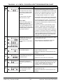
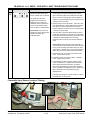
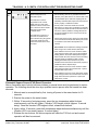
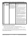
TB-A028-06 - A. O. SMITH - FVIR INTELLI-VENT TROUBLESHOOTING CHART
#
1
2
3
LED STATUS
PROBLEM
Inadequate or no earth ground
sensed by the Intelli-Vent™
control.
1 Ensure the wall outlet is properly grounded.
Power supply to Intelli-Vent™
control has reversed polarity.
1 Ensure the wall outlet is properly wired.
Pressure switch circuit remaining
closed for more than 5 seconds
after heating cycle begins.
Blower does not start.
1 Ensure air pressure switch circuit wiring is correct
and the air pressure switch is not jumpered.
Service Note:
Secure power - disconnect one
wire from the air pressure switch
or the vent temperature limit
switch. Turn power back on blower should start.
4
SOLUTION
Pressure switch circuit remains
open longer than 5 seconds after
the blower is energized.
Blower may run continuously
in this condition.
2 Ensure all ground connections/wires on the water
heater are secure.
2 Ensure all internal 120 VAC wiring connections and
wiring harness have no reversed wires. 120 VAC
“hot” wire must connect to the on/off switch.
2 Secure power to water heater, check continuity of air
pressure switch contacts with wires disconnected.
A If pressure switch contacts show continuity (closed
circuit) replace the pressure switch.
B If pressure switch contacts are open and all wiring
is correct - turn the power off for 10-20 seconds
then on again to clear the error code - if the error
code persists replace the Intelli-Vent™ control.
1 Ensure the blower is running - check for 120 VAC to
the blower when the heating cycle begins, check the
wiring. If the control does not energize the blower replace the Intelli-Vent™ control. If the blower fails to
start when energized - replace the blower assembly.
2 Ensure the air pressure switch sensing tube is
properly connected - not kinked or damaged.
3 Check continuity of vent temperature limit switch replace switch if contacts remain open under 160°F.
Service Note:
To learn more about performing
Air Pressure Switch tests visit
our web site www.hotwater.com
to download technical bulletin
TB-A023-06 Air Pressure
Switches.
4 Ensure the correct size of vent pipe (2”, 3”, 4”) was
used per the installation manual for vent length.
Ensure maximum number of elbows or equivalent
feet of vent pipe has not exceeded maximum limits.
5 Ensure there are no obstructions in the vent pipe.
6 Check air pressure switch performance - check
pressure with a digital manometer - check continuity
of contacts. (see service note in left column) If the
switch proves defective - replace the air pressure
switch and/or the blower assembly as required.
7 If air pressure switch performance test results prove
the air pressure switch is working properly and error
code 4 persists - replace the Intelli-Vent™ control.
5
The Intelli-Vent™ control has
detected an open ignitor circuit.
1 Check wiring to the hot surface ignitor - replace
ignitor assembly if wiring is damaged or worn.
2 Check ignitor assembly plug and the socket on the
Service Note:
Intelli-Vent™ body for good connection. Replace
Ignitors are wearing parts; the
ignitor assembly and/or control if necessary.
resistance (ohms) of a hot
surface ignitor will increase over 3 Check resistance of ignitor at room temperature
(77°F) at the plug end. Replace ignitor if resistance is
time. If the resistance at room
not within 11.5 and 18.8 ohms at room temperature.
temperature is near 18.8 ohms consider replacing the ignitor as a 4 If results from the above tests were good and error
preventative measure.
code 5 persists - replace the Intelli-Vent™ control.
A. O. Smith Water Products Company
Ashland City, Tennessee © 2006
AHSTB02807
1 of 5
Technical Training Department
Intelli-Vent Trouble Chart FVIR AOS.fm
TB-A028-06 - A. O. SMITH - FVIR INTELLI-VENT TROUBLESHOOTING CHART
#
LED STATUS
PROBLEM
Ignition/flame failure.
6
The water heater has reached
the maximum number of retries
and is currently locked out for
one hour.
Cycle the power to the water
heater off and on to reset.
SOLUTION
1 Gas supply is turned off - pressure too low. Ensure
supply and manifold gas pressures are within
requirements in the installation manual. Manifold gas
pressure is non-adjustable if pressure is off by more
than 0.3” W.C. replace the Intelli-Vent™ control.
2 Low supply voltage - should be 115 - 125 VAC.
3 Ensure flame sensor is making good contact with the
burner flame, ensure flame is steady see #8 below.
4 Ensure the flame sensor is clean - use ultra fine steel
wool or Scotch-Brite™ pad to clean flame sensor.
Service Note:
Ignitors are wearing parts; the
5 Ensure the hot surface ignitor is positioned to provide
resistance (ohms) of a hot
consistent ignition.
surface ignitor will increase over
6
Check
for any cracks in ignitor assembly ceramic
time. If the resistance at room
insulators
- replace ignitor assembly if damaged.
temperature is near 18.8 ohms consider replacing the ignitor as a 7 Check resistance of ignitor at room temperature
(77°F) at the plug end. Replace ignitor if resistance is
preventative measure.
not within 11.5 and 18.8 ohms at room temperature.
8 Ensure the correct size of vent pipe (2”, 3”, 4”) was
used per installation manual for vent length. Using
larger pipe than required may cause excessive air
turbulence in the combustion chamber.
7
8
Self diagnostic tests have found
a problem with the gas valve
driver circuit, internal
microprocessor, or other internal
circuits.
1 Turn the power off for 10-20 seconds then on again
to clear these error codes.
Flame signal has been sensed
out of proper sequence.
1 Turn the power off for 10-20 seconds and then on
again to clear this error code.
2 If any of these error codes persist or cannot be
cleared - replace the Intelli-Vent™ control.
9
10
2 Replace the Intelli-Vent™ control if this error code
persists.
Water temperature in the tank
has exceeded 195°F and has
activated the ECO.
1 Turn the power off for 10-20 seconds then on again
to clear this error code.
12
The self diagnostic check
detected one or both of the
temperature adjust buttons are
stuck.
1 Press and release temperature adjust buttons. If the
above action does not clear the error, the control will
continue to regulate water temperature at the last
setting. However, settings will no longer be
adjustable - the control should be replaced.
13
The self diagnostic test has
detected the water temperature
sensor (thermistor) is either
open or shorted.
1 Turn the power off for 10-20 seconds then on again
to clear this error code.
11
A. O. Smith Water Products Company
Ashland City, Tennessee © 2006
AHSTB02807
2 of 5
2 Replace the control if the error code persists.
2 Replace the Intelli-Vent™ control if this error code
persists.
Technical Training Department
Intelli-Vent Trouble Chart FVIR AOS.fm
TB-A028-06 - A. O. SMITH - FVIR INTELLI-VENT TROUBLESHOOTING CHART
#
14
LED STATUS
PROBLEM
SOLUTION
The self diagnostic test has
detected the flammable vapor
sensor is either open or shorted.
1 Turn off power to the water heater. Ensure all FV
sensor wiring, the ignitor assembly plug, and the
ignitor assembly socket on the bottom of the IntelliVent™ control are making good contact. Repair or
replace any worn/damaged components that are not
making a good connection.
The Intelli-Vent control is
programed to lock-out and
display this error code if the
resistance value it senses from
the FV sensor is below 5,000
ohms or above 1,700,000 ohms.
Service Note: To perform this
test the ohm meter used must be
capable of reading up to
2,000,000 ohms.
2 Restore power to the water heater - if the error code
has cleared place the water heater back in operation
and allow it to cycle several times to ensure the
problem has been resolved. If the error code persists
- continue to step 3 below.
3 Turn off power to the water heater. Remove the FV
sensor from it’s bracket on the base ring of the water
heater and disconnect both wires to the sensor. Take
a resistance reading between the two wiring
terminals of the FV sensor and note the resistance
value.
Service Note: Unless the ohm meter used has an
auto-range feature the resistance should be checked
twice. The first reading will be taken using an ohms
scale above 1,700,000 ohms. The second reading is
taken using an ohms scale just above 5,000 ohms.
4 If resistance of the FV sensor is lower than 5,000
ohms - replace the FV sensor.
5 If resistance of the FV sensor is above 1,700,000
ohms - replace the FV sensor.
6 If the resistance of the FV sensor is above 5,000
ohms and lower than 1,700,000 ohms and all the
above steps have been performed - ensure the
wiring and plug between the sensor and the IntelliVent™ control are not damaged or worn - replace the
ignitor assembly if the wiring and/or plug are
damaged/worn.
If the wiring and plug are in good condition - replace
the Intelli-Vent™ control valve
Flammable Vapor Sensor Location / Testing
A. O. Smith Water Products Company
Ashland City, Tennessee © 2006
AHSTB02807
3 of 5
Technical Training Department
Intelli-Vent Trouble Chart FVIR AOS.fm
TB-A028-06 - A. O. SMITH - FVIR INTELLI-VENT TROUBLESHOOTING CHART
#
15
LED STATUS
PROBLEM
The self diagnostic test has
detected the presence of
flammable vapors.
The Intelli-Vent control is
programed to lock-out and
display this error code if the
resistance value it senses from
the FV sensor is above 70,000
ohms but remains below
1,700,000 ohms.
The Intelli-Vent control is in a
hard lock-out condition that
cannot be reset by cycling power
to the water heater. See the
instructions below for the reset
procedure.
SOLUTION
1 Turn off power to the water heater. Carefully check
the surrounding area for any substances such as
gasoline, paint, paint thinners, or cleaners that could
emit flammable vapors. Remove anything that can
potentially emit flammable vapors from the area and
store it properly in a different location.
2 Ensure power to the water heater is turned off.
Remove the FV sensor from it’s bracket on the base
ring of the water heater and disconnect both wires to
the sensor. Take a resistance reading between the
two wiring terminals of the FV sensor and note the
resistance values.
Perform this test once in the area by the water heater
and a second time outdoors after allowing the sensor
to acclimate to the outdoor atmosphere for 5
minutes.
Service Note: These resistance readings should be
taken using an ohm scale above70,000 ohms.
3 If the resistance of the FV sensor is above 70,000
ohms during the indoor test only and the resistance
reading taken in the outdoor atmosphere dropped
below 70,000 ohms. Re-check the area surrounding
the water heater for substances that could be
emitting flammable vapors. Remove any such
substances from the area and store them properly in
a different location. Repeat step 2.
4 If the resistance of the FV sensor is above 70,000
ohms during the indoor and outdoor tests - replace
the flammable vapor sensor.
5 If the resistance of the FV sensor was below 70,000
ohms during the indoor and outdoor tests and all the
steps above have been performed - replace the
Intelli-Vent™ control.
Flammable Vapors Sensed (FVS) Reset Procedure
After a flammable vapor lockout has been initiated, a manual reset must be performed to restore
operation. The following should be done by a qualified service person after the hazard has been
removed:
1 Manual reset is accomplished by first, turning off power to the water heater for 10
seconds.
2 Restore the power to the water heater.
3 Within 10 seconds of restoring power, press the two temperature adjust buttons
simultaneously until the left (green) “Vacation” LED begins to blink (approx. 5 second
delay). Once the Vacation LED begins to blink, release both buttons.
4 Again, within 10 seconds, press both temperature adjust buttons simultaneously until the
Vacation LED is on steady (approx. 5 second delay).
5 Release the two buttons, the microcomputer will clear the FVS lock-out and normal
operation will then be restored.
A. O. Smith Water Products Company
Ashland City, Tennessee © 2006
AHSTB02807
4 of 5
Technical Training Department
Intelli-Vent Trouble Chart FVIR AOS.fm
TB-A028-06 - A. O. SMITH - FVIR INTELLI-VENT TROUBLESHOOTING CHART
#
16
LED STATUS
PROBLEM
LDO (Lint, Dust, and Oil) lockout condition.
Air pressure switch circuit is
opening repeatedly during one
heating cycle. May be caused by
the air pressure switch and/or
the vent temperature limit switch
(these two switches are wired
together in a “series” circuit).
SOLUTION
1 Check/clean intake air screen on the base ring of the
water heater.
2 Check/clean the dilution air screen on the blower
assembly.
3 Check/clean the flame arrestor - see the service note
below.
4 Remove the blower assembly and check the flue
baffle - ensure the flue baffle is in good condition and
properly installed - reinstall as necessary and/or
replace the flue baffle if worn or damaged.
5 Ensure water heater is not over-firing - check burner
orifice size - ensure the correct orifice is installed replace as necessary.
6 Ensure water heater is not over-firing - check
manifold gas pressure - ensure manifold gas
pressure is within 0.3” W.C. of the listed rating on the
Intelli-Vent™ control valve. Manifold gas pressure is
non-adjustable, if manifold gas pressure is off by
more than 0.3” W.C. - replace the Intelli-Vent™
control.
7 Check the vent temperature limit switch - if it is
determined that the vent temperature limit switch is
opening its contacts at normal operating
temperatures during the heating cycle - replace the
vent temperature limit switch.
Service Note: the flame arrestor is accessible
through the intake air opening in the base ring of the
water heater with the intake air screen removed. Use
a non-metallic household brush to clear away any lint
or dust from the ceramic flame arrestor, then vacuum
the surface of the flame arrestor and the base ring air
chamber thoroughly with a household vacuum
cleaner. A suitable vacuum hose attachment can be
fabricated in the field using a short length of 1/2”
PVC pipe with a short radius elbow on one end. Use
tape to temporarily seal it to the vacuum hose.
Additional Recommended Service Publications
• Power-Vent service manual - part number TC-048 R6 (revision 6 or later)
• Intelli-Vent™ service manual supplement - part number GTC-070 R3 (revision 3 or later)
• Air Pressure Switches technical bulletin - number TB-A023-06
Visit our web site at www.hotwater.com to download the above service manual and supplement.
Revision numbers for these service publications are designated by R3, R4, R6, R7, etc. as a suffix
to the part numbers IE: GTC-070 R4
A. O. Smith Water Products Company
Ashland City, Tennessee © 2006
AHSTB02807
5 of 5
Technical Training Department
Intelli-Vent Trouble Chart FVIR AOS.fm