1
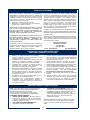
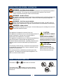
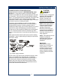
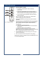
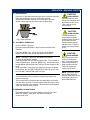
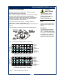
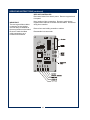
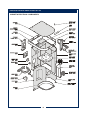
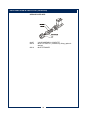
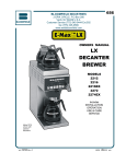
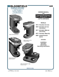
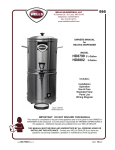
686
BLOOMFIELD INDUSTRIES
2 ERIK CIRCLE, P. O. Box 280
Verdi, NV 89439
telephone: 775-689-5700
fax: 888-492-2783
www.wellsbloomfield.com
OWNERS MANUAL
For
COFFEE BREWERS
MODELS:
0420 Automatic Airpot
Brewer
INCLUDES:
Installation
Operation
Use & Care
Servicing Instructions
Model: 0420 Airpot Brewer
PRINTED IN CHINA
p/n 77111 Rev. B ECN-12887
M686
050622 cps
WARRANTY STATEMENT
It also does not apply if the serial nameplate has been
removed or unauthorized service personnel perform service.
The prices charged by Bloomfield Industries for its products
are based upon the limitations in this warranty. Seller’s
obligation under this warranty is limited to the repair of defects
without charge by a Bloomfield Industries Authorized Service
Agency or one of its sub-agencies. This service will be
provided on customer’s premises for non-portable models.
Portable models (a device with a cord and plug) must be
taken or shipped to the closest Authorized Service Agency,
transportation charges prepaid, for services.
All electrical equipment manufactured by BLOOMFIELD
INDUSTRIES is warranted against defects in materials and
workmanship for a period of one year from the date of original
installation or eighteen (18) months from the date of shipment
from our factory, whichever comes first, and is for the benefit
of the original purchaser, except that:
a. airpots carry a 30 day parts warranty only.
b. dispensers; i.e., tea and coffee carry a 90 days parts
warranty only, excludes decanters.
THE FOREGOING OBLIGATION IS EXPRESSLY GIVEN IN
LIEU OF ANY OTHER WARRANTIES, EXPRESSED OR
IMPLIED, INCLUDING ANY IMPLIED WARRANTY OF
MERCHANTABILITY OR FITNESS FOR A PARTICULAR
PURPOSE, WHICH ARE HEREBY EXCLUDED.
In addition to restrictions contained in this warranty, specific
limitations are shown below (Additional Warranty Exclusions).
Bloomfield Industries Authorized Service Agencies are located
in principal cities.
BLOOMFIELD INDUSTRIES DIVISION / SPECIALTY
EQUIPMENT MANUFACTURING CORPORATION SHALL
NOT BE LIABLE FOR INDIRECT, INCIDENTAL OR
CONSEQUENTIAL DAMAGES OR LOSSES FROM ANY
CAUSE WHATSOEVER.
This warranty is valid in the United States and void elsewhere.
Please consult your classified telephone directory or your food
service equipment dealer; or, for information and other details
concerning warranty, write to:
Service Parts Department
Bloomfield Industries
P.O. Box 280
Verdi, NV 89439
Phone: (775) 689-5700
Fax: (888) 492-2783
This warranty is void if it is determined that upon inspection by
an Authorized Service Agency that the equipment has been
modified, misused, misapplied, improperly installed, or
damaged in transit or by fire, flood or act of God.
SERVICE POLICY AND PROCEDURE GUIDE
ADDITIONAL WARRANTY EXCLUSIONS
1.
2.
3.
4.
5.
6.
7. Full use, care and maintenance instructions are supplied
with each machine. Those miscellaneous adjustments
noted are customer responsibility. Proper attention will
prolong the life of the machine.
8. Travel mileage is limited to sixty (60) miles from an
authorized Service Agency or one of its sub-agencies.
9. All labor shall be performed during normal working hours.
Overtime premium shall be charged to the customer.
10. All genuine Bloomfield replacement parts are warranted
for ninety (90) days from date of purchase on nonwarranted equipment.
Any use of non-genuine
Bloomfield parts completely voids any warranty.
11. Installation, labor and job check-out are not considered
warranty.
12. Charges incurred by delays, waiting time or operating
restrictions that hinder the service technicians ability
to perform services are not covered by warranty.
This includes institutional and correctional facilities.
Resetting of safety thermostats, circuit breakers,
overload protectors, or fuse replacements unless
warranted conditions are the cause.
All problems due to operation at voltages other than
specified on equipment nameplates; conversion to
correct voltage must be the customer’s responsibility.
All problems due to electrical connections not made in
accordance with electrical code requirements and
wiring diagrams supplied with the equipment.
Replacement of items subject to normal wear, to include
such items as knobs and light bulbs. Normal maintenance
functions including adjustment of thermostats, microswitches,
and replacement of fuses and indicating lights are not
covered under warranty.
All problems due to inadequate water supply, such as
fluctuating, or high or low water pressure.
All problems due to mineral/calcium deposits, or
contamination from chlorides/chlorines. De-liming is
considered a preventative maintenance function and is
not covered by warranty.
SHIPPING DAMAGE CLAIMS PROCEDURE
NOTE: For your protection, please note that equipment in
this shipment was carefully inspected and packaged by
skilled personnel before leaving the factory.
Upon acceptance of this shipment, the transportation
company assumes full responsibility for its safe delivery.
IF SHIPMENT ARRIVES DAMAGED:
1. VISIBLE LOSS OR DAMAGE: Be certain that any
visible loss or damage is noted on the freight bill
or express receipt, and that the note of loss or damage
is signed by the delivery person.
2. FILE CLAIM FOR DAMAGE IMMEDIATELY:
Regardless of the extent of the damage.
3.
CONCEALED LOSS OR DAMAGE: if damage is
unnoticed until the merchandise is unpacked, notify the
transportation company or carrier immediately, and file
“CONCEALED DAMAGE” claim with them. This
must be done within fifteen (15) days from the date the
delivery was made to you. Be sure to retain the
container for inspection.
Bloomfield Industries cannot assume liability for damage or
loss incurred in transit. We will, however, at your request,
supply you with the necessary documents to support your
claim.
xi
xi
TABLE OF CONTENTS
WARRANTY STATEMENT
SPECIFICATIONS
FEATURES & OPERATING CONTROLS
PRECAUTIONS & GENERAL INFORMATION
AGENCY LISTING INFORMATION
INSTALLATION INSTRUCTIONS
OPERATION
Program Volume Select Keys
Brew Coffee
CLEANING INSTRUCTIONS
TROUBLESHOOTING SUGGESTIONS
SERVICING INSTRUCTIONS
Deliming Instructions
EXPLODED VIEW & PARTS LIST
WIRING DIAGRAMS
xi
1
2
3
3
4
7
8
9
10
11
12
17
18
21
Thank You for purchasing this
Bloomfield Industries appliance.
Proper installation, professional
operation and consistent
maintenance of this appliance will
ensure that it gives you the very
best performance and a long,
economical service life.
This manual contains the
information needed to properly
install this appliance, and to use,
care for and maintain or repair the
appliance in a manner which will
ensure its optimum performance.
SPECIFICATIONS
MODEL
0420
STYLE
FEATURES
VOLTS
AUTOMATIC
HOT
LO-PROFILE
WATER
120 VAC
AIRPOT
DISPENSER
WATTS
AMPS
1ø
POWER SUPPLY
CORD
1500
12.5
NEMA 5-15P
Also meets Canadian Standards
APPLICABILITY
This manual applies to the following Bloomfield Industries product:
0420
1
FEATURES AND OPERATING CONTROLS - AUTOMATIC BREWERS
Fig. 1 Features & Operating Controls for Automatic Brewers
2
PRECAUTIONS AND GENERAL INFORMATION
WARNING: ELECTRIC SHOCK HAZARD
All servicing requiring access to non-insulated components must be performed by qualified
service personnel. Do not open any access panels which require the use of tools.
Failure to heed this warning can result in electrical shock.
WARNING: INJURY HAZARD
All installation procedures must be performed by qualified personnel with full knowledge of all
applicable electrical and plumbing codes. Failure could result in property damage and
personal injury.
WARNING: ELECTRIC SHOCK HAZARD
Brewer must be properly grounded to prevent possible shock hazard. DO NOT assume a
plumbing line will provide such a ground. Electrical shock will cause death or serious Injury.
WARNING: BURN HAZARD
This appliance dispenses very hot liquid. Serious bodily injury from scalding can occur from
contact with dispensed liquids.
This appliance is intended for commercial use only.
CAUTION:
This appliance is intended for use to brew beverage products for
human consumption. No other use is recommended or
authorized by the manufacturer or its agents.
ELECTRICAL DAMAGE
This appliance is intended for use in commercial establishments,
where all operators are familiar with the appliance use,
limitations and associated hazards. Operating instructions and
warnings must be read and understood by all operators and
users.
DO NOT plug in or energize this
appliance until all Installation
Instructions are read and followed.
Damage to the Brewer will occur if
these instructions are not followed.
CAUTION:
BURN HAZARD
The following trouble shooting, component views and parts lists
are included for general reference, and are intended for use by
qualified service personnel.
This manual should be considered a permanent part of this
appliance. The manual must remain with the appliance if it is
sold or moved to another location.
Exposed surfaces of the
appliance, brew chamber and
airpot may be HOT to the touch,
and can cause serious burns.
AGENCY LISTING INFORMATION
This brewer is
and
listed under UL file E9253.
E9253
E9253
This brewer meets
Standard 4 only when installed,
operated and maintained in accordance with the enclosed
instructions.
STD 4
3
INSTALLATION
READ THIS CAREFULLY BEFORE STARTING THE INSTALLATION
IMPORTANT:
To enable the installer to make
a quality installation and to
minimize installation time, the
following suggestions and tests
should be done before the
actual unit installation is started:
CAUTION:
ELECTRICAL
DAMAGE
DO NOT plug in or energize this
appliance until all Installation
Instructions are read and
followed. Damage to the
Brewer will occur if these
instructions are not followed.
Unpack the unit. Inspect all components for completeness and
condition. Ensure that all packing materials have been removed
from the unit.
Verify that the Spray Head Gasket and Spray Disk are properly
installed.
LEVELING THE UNIT
Verify that an adjustable leg is installed at each of the five
locations on the bottom of the brewer.
Set Brewer in its operating location. Level the Brewer. A spirit
level should be placed on the top of the unit, at the edge, as a
guide when making level adjustments.
Level the unit from left to right and front to back by turning the
adjustable feet. Be sure all feet touch the counter to prevent
tipping.
CAUTION:
UNSTABLE
EQUIPMENT HAZARD
It is very important for safety
and for proper operation that the
brewer is level and stable when
standing in its final operating
position. Provided adjustable,
feet or legs must be installed at
each corner of the unit. Failure
to do so will result in movement
of the brewer which can cause
personal Injury and/or damage
to brewer.
4
INSTALLATION (continued)
PLUMBER’S INSTALLATION INSTRUCTIONS
CAUTION:
Brewer should be connected to a POTABLE WATER, COLD
WATER line. Flush water line before connecting to Brewer.
ELECTRICAL
DAMAGE
DO NOT use a saddle valve with a self-piercing tap for the water
line connection. Such a tap can become restricted by waterline
debris. For systems that must use a saddle tap, shut off the main
water supply and drill a 3/16” (minimum) tap for the saddle
connection, in order to insure an ample water supply. Remember
to flush the line prior to installing the saddle.
The brewer must be installed on a water line with average
pressure between 20 PSI and 90 PSI. If your water pressure
exceeds 90 PSI at anytime, a pressure regulator must be
installed in the water supply line to limit the pressure to not more
than 90 PSI in order to avoid damage to lines and solenoid.
A water shut-off valve should be installed on the incoming water
line in a convenient location (Use a low restriction type valve,
such as a 1/4-turn ball valve, to avoid loss of water flow thru the
valve.
NSF requires that the brewer be able to be moved for cleaning
underneath. Loops of copper tubing will satisfy this requirement.
See Figure 2 below.
DO NOT plug in or energize this
appliance until all Installation
Instructions are read and
followed. Damage to the
Brewer will occur if these
instructions are not followed.
NOTE: Water supply inlet line
must meet certain minimum
criteria to insure successful
operation of the brewer.
Bloomfield recommends 1/4"
copper tubing for installation of
less than 12 feet and 3/8" for
more than 12 feet from a 1/2"
water supply line.
NOTE: This equipment must be
installed to comply with
applicable federal, state and
local plumbing codes and
ordinances.
IMPORTANT:
Water pressure must be
between 20 p.s.i and 90 p.s.i.
flowing pressure. If water
pressure exceeds this value,
or if water pressure varies
greatly, a pressure regulator
must be installed in the water
supply line.
Fig. 2 Water Supply Installation
In some areas, local codes require a backflow preventer (check
valve) to be installed on the inlet water line. If a backflow
preventer is used, you must install a water hammer arrester in
the incoming line, between the backflow preventer and the
brewer inlet, as far away from the brewer as space will allow.
This will relieve the excessive back pressures that can cause
faucet leaks and solenoid malfunctions.
5
INSTALLATION (continued)
WARNING:
ELECTRICIAN’S INSTALLATION INSTRUCTIONS
SHOCK HAZARD
REFER TO ELECTRICAL SPECIFICATIONS - Page 1
Check the nameplate to determine correct electrical service
required for the Brewer to be installed.
Brewer must be properly
grounded to prevent possible
shock hazard. DO NOT
assume a plumbing line will
provide such a ground.
Electrical shock will cause death
or serious injury.
IMPORTANT:
Supply power must match
nameplate for voltage and
phase. Connecting to the
wrong voltage will damage the
brewer or result in decreased
performance. Such damage is
not covered by warranty.
IMPORTANT: Before connecting to electricity, make sure
brewer is connected to the water supply.
All models are equipped with a cord and plug. They require a
115 - 125 volt 20 amp circuit (50/60 Hz, 2 wire plus ground, with
NEMA 5-15R or 5-20R Receptacle).
See Figure 3 at right.
IMPORTANT:
Do not connect brewer to
electrical power until you are
ready to fill the tank. See
instructions on page 7.
IMPORTANT:
The ground prong of the plug is
part of a system designed to
protect you from electrical shock
in the event of internal damage.
Never cut off the ground prong
nor twist a blade to fit an
existing receptacle. Contact a
licensed electrician to install the
proper circuit and receptacle.
GROUND
PIN
NEMA 5-15P
PLUG
NEMA 5-15R
RECEPTACLE
Fig. 3 Power Supply Plug
6
OPERATION
Fig. 4 Water Flow Diagram
A. START-UP
For initial start-up, or if the brewer has not been used for an
extended period of time:
♦ Be sure spray disk and brew gasket are properly installed in the
brew head.
♦ Be sure the water supply is properly connected and the water
supply valve is turned ON and that TANK HEATER SWITCH
is OFF before connecting brewer to electric power.
♦ Be sure the WATER TANK IS FILLED.
IMPORTANT: Fill the water tank before energizing this brewer.
1.
Connect brewer to electric power. Brewer will begin filling. When
solenoid closes, tank is full.
2.
Place an empty container in the hot water well. Press the HOT
WATER DISPENSER BUTTON and dispense one cup of water.
Tank should refill. Discard water.
3.
Press TANK HEATER SWITCH to ON.
4.
When READY light glows, brewer is ready to use.
7
IMPORTANT:
TANK MUST BE FULL
OF WATER BEFORE
CONNECTING BREWER
TO ELECTRIC POWER.
Heating elements will be
damaged if allowed to
operate without being
fully submerged in water.
Damage caused by
operating the brewer
without water in the tank
is NOT COVERED BY
WARRANTY.
See page 8 for setting
delivered water volumes
for VOLUME SELECTION
KEYS.
OPERATION (continued)
B. PROGRAM BREW VOLUMES
♦
Each BREW VOLUME SELECT KEY is individually
programmable.
♦ Keys may be programmed for pulse brewing to optimize
contact times and extraction rates, or to minimize overflowing
the brew chamber when using large amounts of grounds.
♦ Up to 10 pulses may be programmed. Each pulse delay is
fixed at 15 seconds.
1. Place an empty airpot under the brew head. Install the brew
chamber (without filter) under the brew head
2. Press and hold BREW key until beep sounds and the indicator
lights flash.
Fig. 5 Program Volumes
3. Press and release the VOLUME SELECT KEY to be programmed.
Water will begin to flow into the airpot. When the desired water
level is reached, press the key again to stop the water flow.
For pulse brew:
a. Press the key to start the water flow.
b. Press the key again to stop the flow after the time desired for
the first pulse.
c. Press the key again to resume water flow.
d. Repeat until desired total delivered volume is reached.
NOTE: Water flow can be stopped and restarted up to 10 times per
brew. The delay between pulses is fixed at 15 seconds.
4. Press the BREW KEY to enter these settings into memory and
resume normal operation.
5. Run a normal brew with filter and grounds to verify settings.
Repeat steps 1 through 4 to program the other VOLUME SELECT KEY,
or to revise existing settings.
8
OPERATION - BREWING COFFEE
A. PREPARATION
CAUTION:
Place one (1) genuine Bloomfield paper filter in the brew chamber.
Add a pre-measured amount of fresh coffee grounds.
Gently shake the brew chamber to level the bed of grounds.
Slide the brew chamber into place under the brew head.
BURN HAZARD
Exposed surfaces of the
brewer, brew chamber and
airpot may be HOT to the
touch, and can cause
serious burns.
CAUTION:
BURN HAZARD
Fig. 6 Brew Chamber
B. AUTOMATIC OPERATION
Be sure “READY” light is lit.
Place the appropriate EMPTY airpot in place under the brew
chamber.
Press the “BREW” key. A beep will sound and the BREW
INDICATOR LIGHT will glow for the duration of the brew.
NOTE: VOLUME 1 (top key) is the default brew volume.
To brew the OPTIONAL volume:
Press and release the VOLUME 2 (bottom) KEY. The VOLUME 2
INDICATOR will glow. Press the “BREW” key. A beep will sound
and the BREW INDICATOR LIGHT will glow for the duration of the
brew.
At the conclusion of this brew, the system will revert to the default
brew volume, the VOLUME 2 INDICATOR LIGHT will go out, and
the VOLUME 1 INDICATOR LIGHT will glow.
The brew pump will operate for an amount of time determined by
the selected brew volume, drawing a measured quantity of hot
water from the tank.
The hot water will be forced into the brew head where it will spray
over the bed of grounds. Freshly brewed coffee will begin to fill the
container under the brew chamber. When the flow and all dripping
stops, the coffee is ready to serve.
D. PREPARE FOR NEXT BREW
Discard the contents of the brew chamber and rinse it in a sink.
When the ”READY ” light glows, the brewer is ready for
another brew cycle.
9
To avoid splashing or
overflowing hot liquids,
ALWAYS place an EMPTY
airpot under the brew
chamber before starting
the brew cycle. Failure to
comply can cause serious
burns.
CAUTION:
BURN HAZARD
After a brew cycle, brew
chamber contents are
HOT. Remove the brew
chamber and dispose of
used grounds with care.
Failure to comply can
cause serious burns.
NOTE: Excessive use of
the hot water dispense
function during a brew may
decrease the amount of
brew water delivered.
CLEANING INSTRUCTIONS
CAUTION:
PROCEDURE: Clean Coffee Brewer
BURN HAZARD
Brewing and serving
temperatures of coffee are
extremely hot.
Hot coffee will cause
serious skin burns.
PRECAUTIONS: Disconnect brewer from electric power.
Allow brewer to cool.
FREQUENCY:
Daily
TOOLS:
Mild Detergent, Clean Soft Cloth or Sponge
Bristle Brush, Bottle Brush
CAUTION:
SHOCK HAZARD
Do not submerge or immerse
brewer in water.
IMPORTANT:
DO NOT use steel wool, sharp
objects, or caustic, abrasive or
chlorinated cleansers to clean
the brewer or airpots.
1. Disconnect brewer from electric power.
Allow brewer to cool before cleaning.
2. Remove airpot and any cup.
3. Remove and empty brew chamber.
4. Remove the spray disk from the brew head (See figure 7):
Press up on the spray disk ears, then turn the disk to the left
to unlatch. Remove the gasket from inside the brew head.
5. Wipe inside of brew head and area around the brew head
with a soft clean cloth or sponge moistened with clean water.
6. Wash the spray disk in a sink using warm water and a mild
detergent. A bristle brush may be used to clear clogged
spray holes. Rinse the spray disk with clean water and allow
to air dry.
7. Wash the brew chamber in a sink using warm water and a
mild detergent. A bristle brush may be used to clean the
inside. Rinse with clean water and allow to air dry.
Fig. 7 Cleaning
8. Remove airpot drip tray and both grids. Wash in a sink using
warm water and a mild detergent. Wipe out hot water drip
tray with a soft cloth or sponge moistened with warm water.
Reinstall drip tray and grids.
9. Wipe the exterior of the brewer with a soft clean cloth or
sponge moistened with clean water.
10. Reinstall the gasket INSIDE the brew head, then reinstall the
spray disk.
11. Reinstall the brew chamber.
12. Clean airpots by filling with warm soapy water. Scrub the
inside with a bottle brush. Empty and rinse with clean water.
Wipe the exterior with a soft clean cloth or sponge moistened
with clean water. Invert and allow to air dry.
IMPORTANT: DO NOT submerge airpots in water.
Procedure is complete
10
TROUBLESHOOTING SUGGESTIONS
SYMPTOM
POSSIBLE CAUSE
SUGGESTED REMEDY
Water won’t heat
Brewer unplugged or circuit
breaker tripped
Check power supply cord
Check / reset circuit breaker
Temperature setpoint too low
Set for desired temperature
Hi-Limit safety switch tripped
Allow to cool hi-limit will selfreset
Damaged internal component
or wiring
Examine wiring & connectors,
controller, water level probe and
heating element
Repair/replace as needed
Coffee level too high or low
Volume keys not programmed
Program volume keys
Brew chamber overflows
Too many filter papers or wrong
filter paper
Use one (1) genuine Bloomfield
filter per brew
Brew chamber dispense hole
plugged
Thoroughly clean brew
chamber
Too much coffee or too fine a
grind
Use correct grind and amount
of coffee
Not using pulse brew feature
Program vol. key for pulse brew
Spray gasket improperly
installed
Check/reinstall gasket on
INSIDE of brew head
Spray disk plugged
Clean spray disk
No brew (faucet flows OK)
Damaged internal component
or wiring
Check keypad, controller, and
pump
Repair, replace as needed
No brew plus no flow from hot
water faucet
Water supply OFF
Turn water supply ON
Solenoid inlet strainer plugged
Clean strainer
Water filter (if used) plugged
Replace filter element
Damaged internal component
or wiring
Check controller and water level
probe
No flow from hot water faucet
(brew OK)
Damaged internal component
or wiring
Check solenoid and switch
Repair/replace as needed
Poor coffee quality
Keep brewer and airpots clean.
Install optional taste and odor filter, and replace cartridges
regularly.
Use a quality coffee with a consistent roast. Use proper grind
and amount of coffee per brew.
Sprays water from brew head
11
SERVICING INSTRUCTIONS
CAUTION:
SHOCK HAZARD
ACCESS PANELS
TOP PANEL:
Opening access panels on this
brew may expose uninsulated
electrical components.
Disconnect brewer from
electrical power before
removing any panel.
Remove top panel to access hot water tank, thermostat, heating
elements, brew pump and tubing, hot water dispenser solenoid
and piping,
Trouble shooting instructions,
component views and parts lists
in this manual are included for
general reference, and are
intended for use by qualified
service personnel only.
Remove front panel to access controller.
Top panel is held by screws around the edge.
FRONT PANEL:
Remove airpot drip tray. Front panel is held be screws on the
vertical edges and a retaining lip at the top.
SOLENOID DOOR:
Remove solenoid door to access solenoid plumbing connections.
Solenoid door is held by two screws and a retaining lip.
12
SERVICING INSTRUCTIONS (continued)
TEMPERATURE ADJUSTMENT
CAUTION:
Disconnect brewer from electric power. Remove top panel.
Remove button plug from front panel.
Pull vent tube out of tank lid and insert a thermometer of known
accuracy in hole. Reconnect brewer to electrical power.
Place empty container under brew chamber. Energize brewer
and allow unit to heat. When READY light glows, read the
temperature displayed on thermometer.
SHOCK HAZARD
These procedures involve
exposed electrical circuits.
These procedures are to be
performed by qualified
technical personnel only.
Adjust thermostat by turning shaft; clockwise increases
temperature. 1/8 turn = approximately 10ºF.
Refer to Table 1 below for proper brewing temperature based on
altitude.
NOTE:
Optimum brewing temperature
range is 195ºF to 205ºF (90ºC
to 96ºC).
Upon completion, remove thermometer and reinstall the plug.
IMPORTANT:
A mechanical thermostat will
maintain temperature within
±5ºF. To prevent boiling water
in the brewer, thermostat should
be adjusted to a maximum
temperature equal to the local
boiling temperature minus 5ºF.
Fig. 9 Checking and Adjusting Brew Temperature
BOILING
POINT OF
WATER
TEMP. (ºF)
210
205
IDEAL
BREWING
TEMPERATURE
200
195
0
50
0
1,
00
0
1,
50
0
2,
00
0
2,
50
0
3,
00
0
3,
50
0
4,
00
0
4,
50
0
5,
00
0
5,
50
0
6,
00
0
6,
50
0
190
MAXIMUM
TEMPERATURE
SETTING
ELEVATION (feet above seal level)
BOILING
POINT OF
WATER
97
IDEAL
BREWING
TEMPERATURE
RANGE
94
91
88
0
15
0
30
0
45
0
60
0
75
0
90
0
1.
05
0
1.
20
0
1.
35
0
1.
50
0
1.
65
0
1.
80
1. 0
95
0
TEMP. (ºC)
100
ELEVATION (meters above seal level)
Table 1
Boiling Temperature by Altitude
13
MAXIMUM
TEMPERATURE
SETTING
SERVICING INSTRUCTIONS (continued)
IMPORTANT:
Before setting assembly into
tank, make sure tank lid gasket
is properly seated on flange of
lid. DO NOT OVER-TIGHTEN.
REMOVE TANK LID ASSEMBLY
Disconnect brewer from electric power. Turn OFF water supply.
Remove top panel. Pull vent tube, inlet elbow, outlet elbow and
water level probe out of basin pan.
Disconnect all wiring from thermostat, hi-limit, and heating
element.
Loosen nuts on tank hold-down strap. Remove hold-down strap
by sliding short slotted end off of locking stud and lifting it off.
Remove cover assembly by lifting it straight up.
Reassemble in reverse order.
REPLACE THERMOSTAT (COTHERM)
IMPORTANT:
When mounting thermostat, be
sure to insert sensing bulb to
the bottom of the bulb well.
Tighten capillary lock nut only
enough to ensure no water
leakage. Excessive tightening
is not necessary.
Disconnect brewer from electric power. Turn OFF water supply.
Remove top panel.
Disconnect all wiring from thermostat only. Loosen and free jam
nut from pass-thru fitting securing temperature sensing bulb.
Remove two screws holding thermostat to bracket.
Lift out thermostat, sensing bulb and thermostat gasket.
Reassemble in reverse order. BE SURE the bulb well is fully
seated in the tank fitting, and that the temperature sensing bulb is
inserted to the very bottom of the bulb well.
IMPORTANT:
When replacing heating
element, also replace seal
gaskets.
REPLACE HEATING ELEMENT
Remove tank lid assembly per above.
Remove two hex nuts holding element to cover. Pull element
from mounting holes.
Reassemble in reverse order.
14
SERVICING INSTRUCTIONS (continued)
REPLACE SOLENOID
Symptom: Brewer will not flow water; or, brewer drips
continuously from brew head.
NOTE: Wrench p/n 86660 is designed to allow easy removal of
flare nuts from the water inlet fitting
IMPORTANT: Shut-off water to brewer and disconnect brewer
from electric power before removing hoses or wiring.
Remove water supply flare fitting:
a. Slide the 5/8" end of the wrench over the flats on the
inlet fitting of the valve.
b. Hold the wrench to prevent the inlet fitting from turning
while installing or removing the inlet water supply flare
nut.
Fig. 10 Wrench #86660
Remove fill tubing:
Disconnect wiring.
Remove two screws holding solenoid to access door.
Reassemble in reverse order.
CLEAN SOLENOID SCREEN
Symptom: Automatic brewer will not flow water.
Disconnect brewer from electric power. Turn OFF and disconnect
water supply from brewer inlet fitting.
Unscrew water inlet fitting from solenoid.
Using needle-nose pliers, withdraw strainer screen from solenoid.
Clean screen under faucet. A stiff bristle brush may be used if
necessary.
Reinsert screen in solenoid. Be careful to maintain correct
orientation. (The OPEN END of the screen goes in FIRST.)
Reassemble in reverse order.
15
Fig. 11 Clean Strainer Screen
SERVICING INSTRUCTIONS (continued)
REPLACE CONTROLLER
Disconnect brewer from electric power. Remove top panel and
front panel.
IMPORTANT:
The two keypad ribbon cables
connectors are not polarize,
and can easily be installed on
the wrong location on the board.
Be sure to mark the ribbon
cable connectors s as to
location and orientation.
Note location of wire connections. Be sure to mark the two
keypad ribbon cables as to location and orientation. Disconnect
wiring from controller.
Remove four nuts holding controller to cabinet.
Reassemble in reverse order.
16
SERVICING INSTRUCTIONS (continued)
CAUTION:
PROCEDURE: Delime the Water Tank
PRECAUTIONS: Disconnect brewer from electric power.
Allow brewer to cool.
FREQUENCY:
As required (Brewer slow to heat)
TOOLS:
Deliming Solution
Protective Gloves, Goggles & Apron
Mild Detergent, Clean Soft Cloth or Sponge
Bristle Brush, Bottle Brush
Large Sink (or other appropriate work area)
1. Disconnect brewer from electric power. Turn off the water
shut-off valve and disconnect the water supply line from the
brewer inlet fitting.
2. Remove the tank lid assembly as described on page 13.
3. Remove the water tank from the brewer body by lifting
straight up. Empty all water from the tank. Set the tank back
into the brewer.
4. Mix 2 quarts of deliming solution according to the
manufacturer’s directions. Carefully pour the deliming
solution into the water tank. Lower the lid assembly back
onto the tank. Allow to sit for 30 minutes, or as directed by
the manufacturer.
5. At end of soaking period, remove lid assembly from tank.
Thoroughly rinse internal components of lid assembly with
clear water. Using a stiff bristle brush, scrub the heating
element (and faucet water coil on automatic brewers) to
remove lime and calcium build-up. Rinse with clean water.
Store lid assembly in a safe location .
6. Remove the tank from the brewer and empty. Using a stiff
bristle brush, scrub the interior of the water tank to remove
lime and calcium build-up. Rinse with clean water.
7. Set the tank back into the brewer. Reassemble the tank lid to
the water tank. Make sure the gasket is properly in place,
then reinstall the hold-down strap.
8. Reinstall wiring to heating element and thermostat. Reinstall
the hi-limit thermostat (if removed). For automatic brewers,
reassemble piping for the faucet. Verify that all internal
components are dry, then reinstall the top panel.
10. Reconnect brewer to electrical supply and, for automatic
brewers, reconnect water supply.
11. Install the brew chamber without filter paper or grounds.
Run at least three full brew cycles and discard all water
generated.
12. Brewer is ready to use.
17
CHEMICAL BURN
HAZARD
Deliming chemicals may be
caustic. Wear appropriate
protective gloves and goggles
during this procedure.
Never siphon deliming
chemicals or solutions by
mouth.
This operation should only be
performed by qualified and
experienced service personnel.
IMPORTANT: DO NOT spill,
splash or pour water or deliming
solution into or over any internal
component other than the inside
of the water tank.
IMPORTANT: DO NOT allow
any internal components to
come into contact with the
deliming solution. Take care to
keep all internal components
dry.
NOTE: Repeat steps 4 thru 5
as required to remove all scale
and lime build-up.
NOTE: Normally, silicone
hoses do not need to be
delimed. Should deliming
hoses become necessary,
Bloomfield recommends
replacing the hoses.
0420 EXPLODED VIEW & PARTS LIST
CABINET & ELECTRICAL COMPONENTS
18
0420 EXPLODED VIEW & PARTS LIST (continued)
PLUMBING COMPONENTS
19
EXPLODED VIEW & PARTS LIST (continued)
SERVICE PARTS KITS
84427
85218
85219
VALVE ASSEMBLY, COMPLETE
INLET FITTING KIT ( Includes cap, fitting, gasket &
strainer)
INLET STRAINER
20
WIRING DIAGRAM
21
Bloomfield Industries proudly supports CFESA
Commercial Food Equipment Service Association
Bloomfield Industries, Inc.
Division of Carrier Commercial Refrigeration
In US and Canada
Telephone: 775-689-5700
Fax:
888-492-2783
Fax:
800-356-5142 (for orders only)
website: www.wellsbloomfield.com
PRINTED IN CHINA