1
Leica TPS400 Series
User Manual
Version 5.0
English
Electronical Total Station
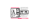
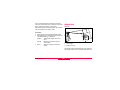
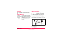
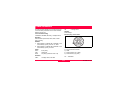
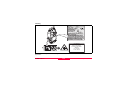
Symbols used in this manual
Congratulations on your purchase of a new
Leica Geosystems Total Station.
The symbols used in this User Manual have the
following meanings:
This manual contains important safety
directions as well as instructions for
setting up the product and operating it.
Refer to "Safety Directions" for further
information.
Read carefully through the User Manual
before you switch on the product.
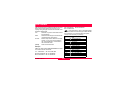
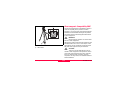
DANGER
Indicates an imminently hazardous situation
which, if not avoided, will result in death or serious
injury.
WARNING
Indicates a potentially hazardous situation
or an unintended use which, if not avoided, could
result in death or serious injury.
CAUTION
Indicates a potentially hazardous situation
or an unintended use which, if not avoided, may
result in minor or moderate injury and / or appreciable material, financial and environmental
damage.
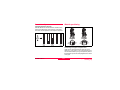
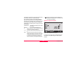
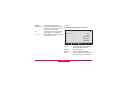
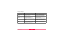
Product identification
The model and the serial number of your product is
indicated on the type plate.
Enter the model and the serial number in your
manual and always refer to this information when
you need to contact your agency or Leica Geosystems authorized service workshop.
Type: ____________
TPS400-5.0.1en
)
Important paragraphs which must be
adhered to in practice as they enable the product to
be used in a technically correct and efficient manner.
Serial no.: ____________
2
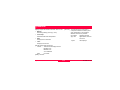
Trademarks
•
Windows is a registered trademark of Microsoft
Corporation
All other trademarks are the property of their respective owners.
3
TPS400-5.0.1en
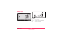
Validity of this manual
Description
General
This manual applies to all TPS400 Series instruments. Where there are differences between
the various models they are clearly described.
Telescope
•
When measuring distances to a reflector with EDM mode "IR" this telescope type uses
a wide visible red laser beam, which emerges coaxially from the telescope's objective.
•
Instruments that are equipped with a reflectorless EDM additionally offer the EDM
modes "RL" and "RL-Prism". When using these EDM modes a narrow visible red laser
beam is used to measure distances.
TPS400-5.0.1en
4
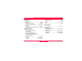
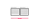
Contents - Overview
Contents - Overview........................... 5
System Info ..................................... 113
Contents.............................................. 6
Instrument Protection with PIN ..... 114
Introduction ........................................ 9
Care and Storage ............................ 115
Operating the product...................... 18
Safety Directions ............................ 122
Measuring Preparation / Setting up 26
Technical Data ................................ 143
FNC Key ............................................ 43
International Limited Warranty,
Software License Agreement ........ 153
Programs........................................... 50
Index ................................................ 155
Settings ............................................. 93
EDM Settings .................................... 98
File Management ............................ 103
Start-up sequence .......................... 106
Calibrations..................................... 107
COMM Parameters ......................... 111
Data Transfer .................................. 112
Contents - Overview
5
TPS400-5.0.1en
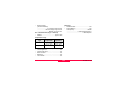
Contents
Introduction .................................................... 9
Menu tree........................................................ 25
Special features ............................................. 10
Important parts............................................... 11
Technical terms and abbreviations ............ 12
Area of applicability ....................................... 15
PC Program Package
Leica Geo Office Tools (LGO-Tools) ......... 15
Measuring Preparation / Setting up .. 26
Unpacking ....................................................... 26
Inserting / Replacing Battery ....................... 27
External power supply for total
station .............................................................. 29
Setting up the tripod...................................... 30
Instrument Setup ........................................... 31
Levelling up with the electronic level
step-by-step ................................................... 33
Laser intensity ................................................ 34
Hints for positioning ...................................... 34
Input mode - method 1 ................................. 35
Input mode - method 2 ................................. 35
Edit mode........................................................ 36
Installation on the PC ..................................... 15
Program content............................................. 15
Power Supply ................................................. 17
Operating the product ............................. 18
Keypad ............................................................ 18
Fixed keys ...................................................... 19
Trigger key...................................................... 19
Selection of Language.................................. 19
Distance measurement ................................ 20
Softkeys .......................................................... 23
Symbols .......................................................... 24
Erasing characters ......................................... 36
Inserting characters........................................ 37
Numerical and Alphanumerical input ......... 38
Pointsearch .................................................... 40
Wildcard search ............................................. 41
Measuring ....................................................... 42
Status symbol "EDM type" ............................. 24
Status symbol "Battery capacity" ................... 24
Status symbol "Compensator" ....................... 24
Status symbol "Offset" ................................... 24
TPS400-5.0.1en
6
Contents
FNC Key.......................................................... 43
Construction ................................................... 80
COGO (optional) ............................................ 82
Reference Plane (optional) ............................ 88
Coding ............................................................. 91
Light On /Off ................................................... 43
Level/Plummet ............................................... 43
IR/ RL Toggle ................................................. 43
Laser Pointer .................................................. 43
Free-Coding ................................................... 43
Units................................................................. 43
Delete Last Record ....................................... 44
Lock with PIN ................................................. 44
Target Offset .................................................. 44
Height Transfer .............................................. 47
Hidden Point................................................... 48
Settings........................................................... 93
EDM Settings ............................................... 98
File Management ...................................... 103
Start-up sequence ................................... 106
Calibrations ................................................ 107
Line-of-sight error (Hz-collimation)........... 108
V-Index (Vertical index error) .................... 108
Programs ....................................................... 50
Application pre-settings ................................ 50
COMM Parameters .................................. 111
Setting job ...................................................... 50
Setting Station................................................ 51
Orientation...................................................... 52
Applications .................................................... 56
Introduction .................................................... 56
Surveying ....................................................... 57
Stake out ........................................................ 58
Free Station.................................................... 60
Reference Line............................................... 67
Tie Distance ................................................... 73
Area & Volume ............................................... 76
Remote Height ............................................... 79
Contents
Data Transfer ............................................. 112
System Info ................................................. 113
Instrument Protection with PIN......... 114
Care and Storage ..................................... 115
Transport ...................................................... 115
In the field..................................................... 115
Inside vehicle ............................................... 116
7
TPS400-5.0.1en
Technical Data........................................... 143
Shipping ....................................................... 116
Storage.......................................................... 116
Atmospheric correction .............................. 149
Batteries ....................................................... 117
Cleaning ....................................................... 118
Checking and adjusting .............................. 119
Tripod ........................................................... 119
Circular level ................................................ 119
Circular level on the tribrach ........................ 120
Laser plummet ............................................. 120
Reduction formulae ...................................... 151
International Limited Warranty,
Software License Agreement............. 153
International Limited Warranty .................. 153
Software License Agreement .................... 153
Index............................................................... 155
Safety Directions...................................... 122
Intended Use ................................................ 122
Permitted use ............................................... 122
Adverse use ................................................. 122
Limits of Use ................................................ 123
Responsibilities ............................................ 124
Hazards of Use ............................................ 125
Laser classification...................................... 129
General ........................................................ 129
Distancer, Measurements with Reflectors
(IR mode) ..................................................... 129
Distancer, Measurements without Reflectors
(RL mode) .................................................... 132
Electronic Guide Light EGL.......................... 136
Laser plummet ............................................. 137
Electromagnetic Compatibility EMC ........ 139
FCC Statement (Applicable in U.S.) ........ 141
TPS400-5.0.1en
8
Contents
Introduction
The Leica Geosystems TPS400 is a high-quality
electronic total station.
Its innovative technology makes the daily surveying
jobs easier.
The instrument is ideally suited for simple construction surveys and setting out tasks.
The easy operation of the instrument functions can
be learned without problems in no time.
Introduction
9
TPS400-5.0.1en
Special features
•
•
•
•
•
•
•
Easy and quickly to learn !
Interactive keys; with large and clear LCD.
Small, light-weight and easy-to-use.
Measurements without reflector with the integrated visible laser beam (TCR instruments).
Additional trigger key on side cover.
Continuous drives for horizontal and vertical
angles (tangent screws).
With laser plummet as standard.
TPS400-5.0.1en
10
Introduction
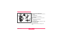
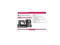
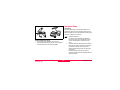
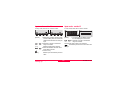
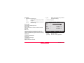
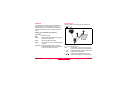
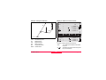
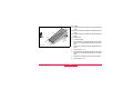
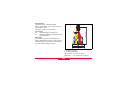
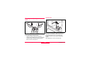
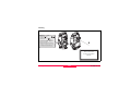
Important parts
1)
2)
3)
4)
5)
6)
7)
8)
9)
10)
11)
12)
Instrument with EGL
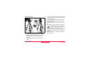
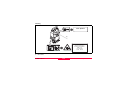
Introduction
13)
14)
15)
16)
17)
18)
Instrument without EGL
11
Optical sight
Integrated guide light EGL (optional)
Vertical drive
Battery
Battery stand for GEB111
Battery cover
Eyepiece; focussing graticule
Focussing telescope image
Detachable carrying handle with mounting
screws
Serial interface RS232
Foot screw
Objective with integrated Electronic Distance
Measurement (EDM); Beam exit
Display
Keyboard
Circular level
On/Off key
Trigger key
Horizontal drive
TPS400-5.0.1en
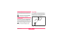
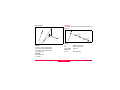
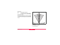
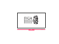
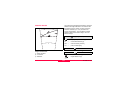
Technical terms and abbreviations
ZA = Line of sight / collimation axis
Telescope axis = line from the reticle to the centre of
the objective.
SA = Standing axis
Vertical rotation axis of the telescope.
KA = Tilting axis
Horizontal rotation axis of the telescope (Trunion
axis).
V = Vertical angle / zenith angle
VK = Vertical circle
With coded circular division for reading the V-angle.
Hz = Horizontal direction
HK = Horizontal circle
With coded circular division for reading the Hzangle.
TPS400-5.0.1en
12
Introduction
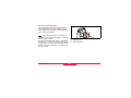
Plumb line / Compensator
Direction of gravity. The compensator defines the plumb line within
the instrument.
Standing axis inclination
Angle between plumb line and
standing axis. Standing axis tilt is
not an instrument error and is not
eliminated by measuring in both
faces. Any possible influence it may
have on the Hz-direction resp. Vangle is eliminate by the dual axis
compensator.
Zenith
Point on the plumb line above the
observer.
Line-of-sight error (Hz-collimation)
The line-of-sight error is the deviation from the perpendicular
between tilting axis and line-ofsight. This could be eliminated by
measuring in both faces.
Reticle
Glass plate within the telescope
with reticle.
V-Index (Vertical index error)
With horizontal line-of-sight the Vcircle reading should be exactly
90°(100gon). The deviation from
this values is termed V-index (i).
Introduction
13
TPS400-5.0.1en
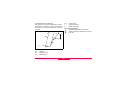
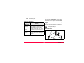
hr
hi
E0
N0
H0
E
N
H
TPS400-5.0.1en
14
Indicated meteorological corrected slope
distance between instrument tilting axis and
centre of prism/laser spot (TCR).
Indicated meteorological corrected horizontal distance.
Height difference between station and
target point.
Reflector height above ground
Instrument height above ground
Station coordinate (Easting)
Station coordinate (Northing)
Station height
Easting of target point
Northing of target point
Height of target point
Introduction
For the installation call program "setup.exe" in the
directory \LGO-Tools on the CD-ROM and follow
the input instructions of the installation program.
Area of applicability
This User Manual is valid for all instruments of the
TPS400 Series.
Program content
After successful installation the following programs
appear:
PC Program Package
Leica Geo Office Tools (LGO-Tools)
Tools
The program package LGO-Tools is used for the
data exchange between the Total Station and the
PC. It contains several auxiliary programs in order to
support your use of the instrument.
•
Installation on the PC
•
The installation program can be found on the CDROM supplied. Please note that LGO-Tools can
only be installed on computers with MS Windows
2000, XP and Vista operating systems.
•
•
)
Any previous versions of LGO-Tools on
your computer must be uninstalled first before
installing the new version.
Introduction
Data Exchange Manager
For data exchange of coordinates, measurements, codelists and output formats between
instrument and PC.
Coordinate Editor
Import/Export as well as creating and
processing of coordinate files.
Codelist Manager
For creating and processing of codelists.
Software Upload
For loading system software and EDM-software.
)
For EDM Software upload only LGO/LGOTools Software Version 3.0 or higher must be used
for error free operation.
15
TPS400-5.0.1en
Not using the correct upload Software can
permanently damage the instrument.
)
Before the Software Upload, always insert a
charged battery into the instrument.
• Format Manager
For creating of own, special formatted data
output files.
• Configuration Manager
Import/Export as well as creating of instrument
configuration.
)
For more information about LGO-Tools refer
to the comprehensive Online Help.
TPS400-5.0.1en
16
Introduction
1
2
3
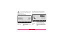
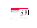
Power Supply
Use the Leica Geosystems batteries, chargers and
accessories or accessories recommended by Leica
Geosystems to ensure the correct functionality of
the instrument.
Power for the instrument can be supplied either
internally or externally. An external battery is
connected to the instrument using a LEMO cable.
• Internal battery:
One GEB111 or 121 battery fit in the battery
compartment.
• External battery:
One GEB171 battery connected via cable.
Introduction
GEB121
GEB111
Single cells in the battery adapter GAD39
Your Leica Geosystems instrument is powered by
rechargeable plug-in batteries. For this product, we
recommend the basic battery (GEB111) or the Pro
battery (GEB121). Optionally six single cells can be
used with the GAD39 battery adapter.
Six single cell batteries (1.5 V each) supply 9 Volts.
The voltmeter on the instrument is designed for a
voltage of 6 Volts (GEB111/ GEB121).
)
The battery charge is not displayed correctly
when using single cells. Use the single cells with the
battery adapter as emergency power supply. The
advantage of the single cells is in a lower rate of
discharge even over long periods.
17
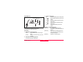
TPS400-5.0.1en
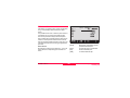
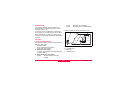
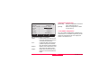
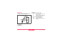
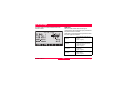
Operating the Instrument
The On / Off key is located on the side cover of the
TPS400.
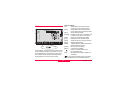
1) Focus
Actively measured field.
2) Symbols
3) Fixed keys
Keys with firmly assigned functions.
4) Navigation keys
Control of input bar in edit and input mode or
control of focus bar.
5) Function keys
Are assigned the variable functions displayed at
the bottom of the screen.
6) Softkey bar
Displays functions that can be called up with the
function keys.
)
All shown displays are examples. It is
possible that local software versions are different to
the basic version.
Keypad
TPS400-5.0.1en
18
Operating the Instrument
Fixed keys
[PAGE]
[MENU]
[USER]
[FNC]
[ESC]
Trigger key
Scrolls to next page when a dialogue
consists of several pages.
Accesses programs, settings, the data
manager, adjustments, communications parameters, system information
and data transfer.
Key, programmable with function from
the FNC menu.
Quick-access to measurementsupporting functions.
Quit a dialog or the edit mode with activation of the "previous" value. Return to
next higher level.
Confirm an input; continue to the next
field.
Operating the Instrument
The measurement trigger has three settings (ALL,
DIST, OFF).
The key can be activated in the configuration menu.
Selection of Language
After switching on the instrument the user is able to
choose his preferred language.
The dialog to choose the language is only shown if
two languages are loaded onto the instrument and
Lang.choice: On is set in Settings dialog.
To load an additional language connect the instrument to LGO Tools Version 4.0 or higher via the
serial interface and load using "LGO Tools - Software Upload".
19
TPS400-5.0.1en
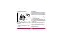
Distance measurement
A laser distancer (EDM) is incorporated into the
instruments of the TPS400 series.
In all versions, the distance can be determined by
using a laser beam which emerges coaxially from
the telescope objective.
)
Measurements to strongly reflecting
targets such as to traffic lights in Reflector EDM
mode without prism should be avoided. The
measured distances may be wrong or inaccurate.
For applications without reflector, a special arrangement of the EDM, and appropriate arrangement of
the beam paths, enable ranges of over five kilometres to be attained with standard prisms.
Miniprisms, 360° reflectors and reflector tapes can
also be used, and measurement is also possible
without a reflector.
If e.g. people, cars, animals, swaying branches, etc.
cross the laser beam while a measurement is being
taken, a fraction of the laser beam is reflected and
may lead to incorrect distance values.
Avoid interrupting the measuring beam while taking
reflectorless measurements or measurements using
reflective foils. Measurements to prism reflectors are
only critical if an object crosses the measuring beam
at a distance of 0 to 30m and the distance to be
measured is more than 300m.
In practice, because the measuring time is very
short, the user can always find a way of avoiding
these critical situations.
)
Very short distances may be measured
reflectorless in IR mode to well reflecting targets.
Note that the distances are corrected with the additive constant defined for the active reflector.
)
When a distance measurement is triggered, the EDM measures to the object which is
in the beam path at that moment.
TPS400-5.0.1en
20
Operating the Instrument
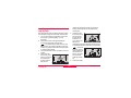
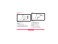
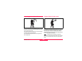
Reflectorless
)
Be sure that the laser beam is not reflected
by anything close to the line of sight (e.g. highly
reflective objects).
)
When a distance measurement is triggered,
the EDM measures to the object which is in the
beam path at that moment. In case of temporary
obstruction (e.g. a passing vehicle, heavy rain, fog
or snow) the EDM may measure to the obstruction.
)
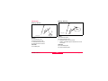
When measuring longer distances, any
divergence of the red laser beam from the line of
sight might lead to less accurate measurements.
This is because the laser beam might not be
reflected from the point at which the crosshairs are
pointing.
Therefore, it is recommended to verify that the Rlaser is well collimated with the telescope line of
sight (refer to the chapter "Checking and adjusting").
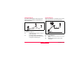
Incorrect result
)
Do not measure with two instruments to the
same target simultaneously.
Correct result
Operating the Instrument
21
TPS400-5.0.1en
Red laser to prisms
)
Accurate measurements to prisms should
be made with the standard program (Reflector EDM
mode).
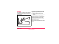
Red laser to reflector tape
The visible red laser beam can be used to measure
to reflective foils, also. To guarantee the accuracy
the red laser beam must be perpendicular to the
reflector tape and it must be well adjusted (refer to
the chapter "Checking and adjusting").
)
Make sure the additive constant belongs to
the selected target (reflector).
TPS400-5.0.1en
22
Operating the Instrument
General softkeys:
[ALL]
Starts distance and angle measurements and saves measured values.
[DIST]
Starts distance and angle measurements without saving measured values.
[REC]
Saves displayed values.
[ENTER] Deletes current value in the display and
is ready for the input of a new value.
[ENH]
Opens the coordinate input mode.
[LIST]
Displays the list of available points.
[FIND]
Starts the search for the point entered.
[EDM]
Displays EDM settings.
[IR/RL]
Toggles between reflector and reflectorless measurement modes.
[PREV]
Back to last active dialog.
[NEXT]
Continue to next dialog.
Returns to highest softkey level.
To next softkey level.
[OK]
Set displayed message or dialog and
quit dialog.
Softkeys
Under softkeys, a selection of commands and functions is listed at the bottom of the screen. They can
be activated with the corresponding function keys.
The available scope of each function depends on
the applications / functions currently active.
Operating the Instrument
)
Find further information about menu/application specific buttons in the relevant sections.
23
TPS400-5.0.1en
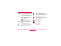
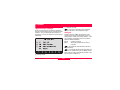
Status symbol "EDM type"
Symbols
Reflector EDM mode for measuring to
prisms and reflective targets.
Reflectorless EDM for measuring to all
targets.
Depending on software version different symbols
are displayed indicating a particular operating
status.
A double arrow indicates choice fields.
Status symbol "Battery capacity"
The battery symbol indicates the level of
the remaining battery capacity (75% full
shown in the example).
Using the navigation keys the
desired parameter can be
selected.
Quits a selection with the enter
key or the navigation keys.
Status symbol "Compensator"
Compensator is on.
Indicates that several pages are available which can be selected with
[PAGE].
Compensator is off.
Indicates telescope position I or II.
Status symbol "Offset"
Indicates that Hz is set to "left side angle
measurement" (anti-clockwise).
!
TPS400-5.0.1en
24
Offset is active.
Operating the Instrument
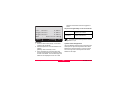
Menu tree
—— File Management
—— Job
—— Fixpoints
—— Measurements
—— Codes
—— Initialize Memory
—— Memory Statistic
Menu
—— Calibrations
—— Hz-Collimation
—— V-Index
—— View Calibration Data
—— Communication Parameters
—— Baudrate
—— Databits
—— Parity
—— Endmark
—— Stopbits
—— Data Transfer
—— Job
—— Data
—— Format
—— System Info
—— Battery
—— Instrument temperature
—— Date
—— Time
—— Start-up sequence
[MENU] >
Confirm menu selection.
[PAGE]
Scroll to next page.
)
Depending on user interface sequence and
arrangement of menu items may be different.
Menu
—— Programs
—— Surveying
—— Setting out
—— Free Station
—— Reference line
—— Tie Distance
—— Area & Volume
—— Remote Height
—— Construction
—— COGO
—— Reference Plane
—— Settings
—— Contrast, Trigger Key, USER key, V-Setting,
Tilt Correction
—— Sector Beep, Beep, Hz Incrementation,
Reticle Illumin., DSP Heater
—— Data Output, GSI 8/16, Mask 1/2/3
Hz Collimation, Auto-Off, Language
—— Min. Reading, Angle Unit, Distance Unit, Distance Decimals
Temperature, Pressure
—— EDM Settings
—— EDM-Mode
—— Prism Type
—— Prism Constant
—— Laser Pointer
—— Guide Light
Operating the Instrument
—— PIN Protection
25
TPS400-5.0.1en
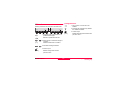
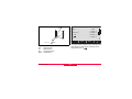
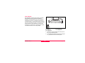
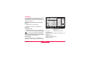
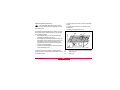
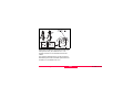
Measuring Preparation / Setting up
1) Data cable (optional)
2) Zenith eyepiece or eyepiece for steep angles
(optional)
3) Total station
4) Removable tribrach (optional)
5) Battery charger and accessories (optional)
6) Adjustment tools
7) Battery GEB111 (optional)
8) GAD105 Mini prism adapter (optional)
9) Battery GEB121 (optional)
10) Tip for mini prism (optional)
11) Spacing bracket GHT196 for height meter
(optional)
12) Height meter GHM007 (optional)
13) Protective cover / Lens hood
14) Mini prism rods
15) Mini prism + holder (optional)
16) User Manual
17) Counterweight for Zenith eyepiece (optional)
Unpacking
Remove TPS400 from transport case and check for
completeness:
1
11
2
3
4
5
6
12
13
14
15
7
8
9
10
16
17
TPS400-5.0.1en
26
Measuring Preparation /
Setting up
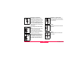
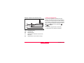
2. Remove battery.
Inserting / Replacing Battery
3. Insert battery into battery holder.
1. Remove battery holder.
4. Insert battery holder into the instrument.
)
Insert battery correctly (note pole markings
on the inside of the battery holder). Check and insert
battery holder true to side into the housing.
• To charge the battery refer to chapter "Charging
the batteries".
• For the type of battery refer to chapter "Technical data".
Measuring Preparation /
Setting up
27
TPS400-5.0.1en
)
)
When using the GEB121 battery, remove
the spacer for the GEB111 from the battery
compartment.
)
•
•
•
•
Charging / first-time use
The battery must be charged prior to using for
the first time because it is delivered with an
energy content as low as possible.
For new batteries or batteries that have been
stored for a long time (> three months), it is
effectual to make 3 - 5 charge/discharge cycles.
The permissible temperature range for charging
is between 0°C to +35°C / +32°F to +95°F. For
optimal charging we recommend charging the
batteries at a low ambient temperature of +10°C
to +20°C/+50°F to +68°F if possible.
It is normal for the battery to become warm
during charging. Using the chargers recommended by Leica Geosystems, it is not possible
to charge the battery if the temperature is too
high.
TPS400-5.0.1en
28
Operation/Discharging
The batteries can be operated from -20°C to
+55°C/-4°F to +131°F.
Low operating temperatures reduce the capacity
that can be drawn; very high operating temperatures
reduce the service life of the battery.
Measuring Preparation /
Setting up
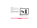
External power supply for total
station
To meet the conditions stipulated for electromagnetic acceptability when powering the TPS400 from
an external source, the supply cable used must be
equipped with a ferrite core.
)
The Lemo plug with the ferrite core always
has to be attached at the instrument side.
For assembling open up one ferrite core and clip it
around the supply cable, about 2cm away from the
Lemo plug, before using the supply cable for the first
time together with a TPS400 instrument.
The cables supplied along with your instrument
include a ferrite core as standard.
If you are using older cables without ferrite core, it's
necessary to attach ferrite cores to the cable.
If you need additional ferrite cores, please contact
your local Leica Geosystems agency. The sparepart number of the ferrite core is 703 707.
Measuring Preparation /
Setting up
29
TPS400-5.0.1en
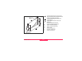
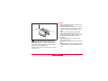
1. Loosen the clamping screws on the tripod legs,
pull out to the required length and tighten the
clamps.
2. In order to guarantee a firm foothold sufficiently
press the tripod legs into the ground. When
pressing the legs into the ground note that the
force must be applied along the legs.
Setting up the tripod
)
When setting up the tripod pay attention to a
horizontal position of the tripod plate.
Slight corrections of inclination can be made with the
foot screws of the tribrach. Larger corrections must
be done with the tripod legs.
)
When using a tribrach with an optical
plummet, the laser plummet cannot be used.
TPS400-5.0.1en
30
Measuring Preparation /
Setting up
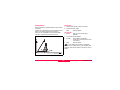
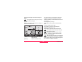
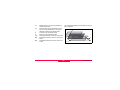
Instrument Setup
Description
This topic describes an instrument setup over a
marked ground point using the laser plummet. It is
always possible to set up the instrument without the
need for a marked ground point.
)
•
Careful handling of tripod
• Check all screws and bolts for correct fit.
• During transport always use the cover supplied.
• Use the tripod only for surveying tasks.
•
•
Measuring Preparation /
Setting up
31
Important features:
It is always recommended to shield the
instrument from direct sunlight and avoid
uneven temperatures around the instrument.
The laser plummet described in this topic is
built into the vertical axis of the instrument.
It projects a red spot onto the ground,
making it appreciably easier to centre the
instrument.
The laser plummet cannot be used in
conjunction with a tribrach equipped with an
optical plummet.
TPS400-5.0.1en
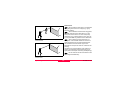
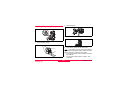
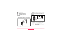
3. Turn on the instrument and switch on the laser
plummet and electronic level by pressing [FNC]
> [Level/Plummet].
4. Move the tripod legs (1) and use the tribrach
footscrews (6) to centre the plummet (4) over
the ground point.
5. Adjust the tripod legs to level the circular level
(7).
6. By using the electronic level turn the tribrach
footscrews (6) to precisely level the instrument.
Refer to "Levelling up with the electronic
level step-by-step" for more information.
7. Centre the instrument precisely over the ground
point (4) by shifting the tribrach on the tripod
plate (2).
8. Repeat steps 6. and 7. until the required accuracy is achieved.
Setup step-by-step
7
2
3
6
1
1
1
5
)
5
4
5
1. Extend the tripod legs to allow for a comfortable
working posture. Position the tripod over the
marked ground point, centring it as well as
possible.
2. Fasten the tribrach and instrument onto the
tripod.
TPS400-5.0.1en
32
Measuring Preparation /
Setting up
rotating the footscrews. When the electronic
level is centred the arrows are replaced by
checkmarks.
Levelling up with the electronic level
step-by-step
The electronic level can be used to precisely level up
the instrument using the footscrews of the tribrach.
1. Turn on the instrument and switch on the electronic level by pressing [FNC] > [Level/
Plummet].
2. Centre the circular level approximately by
turning the footscrews of the tribrach.
)
The bubble of the electronic level and
the arrows for the rotating direction of the footscrews only appear if the instrument tilt is inside
a certain levelling range.
3. Turn the instrument until it is parallel to two footscrews.
4. Centre the electronic level of this
axis by turning the
two footscrews.
Arrows show the
direction for
Measuring Preparation /
Setting up
33
5. Centre the electronic level for the
second axis by
turning the last
footscrew. An
arrow shows the
direction for
rotating the footscrew. When the electronic level
is centred the arrow is replaced by a checkmark.
)
When the
electronic level is
centred and three
checkmarks are
shown, the instrument has been
perfectly leveled
up.
6. Accept with [OK].
TPS400-5.0.1en
Laser intensity
Hints for positioning
Changing the laser intensity
External influences and the surface conditions may
require the adjustment of the intensity of the laser.
The laser can be adjusted in 25% steps as required.
Positioning over pipes or depressions
Under some circumstances the laser spot is not
visible (e.g. over pipes). In this case, the laser spot
can be made visible by using a transparent plate so
that the laser spot can be easily aligned to the centre
of the pipe.
TPS400-5.0.1en
34
Measuring Preparation /
Setting up
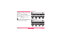
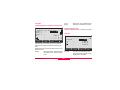
Input mode - method 1
Input mode - method 2
In entry mode, enter text or numeric values.
In entry mode, enter text or numeric values.
PtId:
F1
F2
F3
F4
[INPUT]
[>>>]
-
[ESC]
1. Delete entry, display numeric/ alphanumeric softkey bar. The cursor indicates that the instrument is ready for
input.
2. Selection of range of characters/
range of numbers.
Additional characters/ numbers.
3. Select the desired character. Character shifts to the left.
4. Confirm entry.
PtId:
1234
*ABC
PQRS
&?#@
5678
DEFG
TUVW
%*/
90.
HIJK
XYZ_
+ LMNO
.$ !
*ABC
DEFG
HIJK
LMNO
F1
F2
F3
F4
[INPUT]
1. The full range of available characters are displayed on the screen.
2. Selection of range of characters/
range of numbers.
Proceed with steps 3 and 4 from method 1.
)
The method you like to use can be set in the
settings.
Deletes input and restores previous
value.
Measuring Preparation /
Setting up
35
TPS400-5.0.1en
Erasing characters
Edit mode
1. Place cursor on character to be
deleted.
2. Pressing the navigation key deletes
the relevant character.
3. Confirm input.
Existing characters are changed in the edit mode.
Info4:
PREP
Info4:
PROP
[ESC]
1. Start edit mode. Vertical edit bar is
positioned flush right.
Edit bar is positioned flush left.
-
2. Select range of characters/ range of
numbers.
Additional characters / numbers.
-
3. Overwrite existing characters.
[>>>]
Deletes the change and restores the
previous value.
4. Confirm input.
[ESC]
Deletes change and restores
previous value.
TPS400-5.0.1en
36
Measuring Preparation /
Setting up
Inserting characters
If a character was skipped (e.g. -15 instead of -125)
you can insert it later.
1. Place cursor on "1".
2. Inserts an empty character on the
right of "1".
-
3. Select range of characters /range of
numbers.
-
4. Select relevant character.
5. Confirm input.
Measuring Preparation /
Setting up
37
TPS400-5.0.1en
Numerical input
Numerical and Alphanumerical input
Input is made with the softkey bar and the assigned
function keys.
Position the marker in the relevant field.
[INPUT]
1. Calls up the input dialogue.
[>>>]
2. Select range of characters /range of
numbers.
Additional characters / numbers.
3. Confirm input.
)
Alphanumerical input
Selection is limited to valid digits for entries,
that due to their display characteristics, fall into a
certain range (e.g. angles in degrees).
TPS400-5.0.1en
38
Measuring Preparation /
Setting up
Character set
Entry mode contains the following characters for
numeric and alphanumeric input.
Numerical
"+"
"-"
"."
"0-9"
(ASCII 43)
(ASCII 45)
(ASCII 46)
(ASCII 48 - 57)
The character entry "*" can be used in data fields
where point numbers or codes can be searched for.
Signs
+/- In the alphanumeric character set "+" and "-" are
treated as normal alphanumeric characters with
no mathematical function.
Alphanumerical
" "
"!"
"#"
"$"
"%"
"&"
"("
")"
"*"
"+"
","
"-"
"."
"/"
":"
"<"
"="
">"
"?"
"@"
" A - Z"
"_"
"‘"
Measuring Preparation /
Setting up
(ASCII 32) [space]
(ASCII 33)
(ASCII 35)
(ASCII 36)
(ASCII 37)
(ASCII 38)
(ASCII 40)
(ASCII 41)
(ASCII 42)
(ASCII 43)
(ASCII 44)
(ASCII 45)
(ASCII 46)
(ASCII 47)
(ASCII 58)
(ASCII 60)
(ASCII 61)
(ASCII 62)
(ASCII 63)
(ASCII 64)
(ASCII 65 .. 90)
(ASCII 95)
[Underscore]
(ASCII 96)
Additional characters
* Place holder during Wildcard point search (see
chapter "Wildcard search").
)
)
"+" / "-" appears only in the front position of
an input.
In the edit mode the position of the decimal
place cannot be changed. The decimal place is
skipped.
39
TPS400-5.0.1en
Pointsearch
Pointsearch is a global function used by applications
to e.g. find internally saved measured or fixed
points.
It is possible for the user to limit the point search to
a particular job or to search the whole storage.
The search procedure always finds fixed points
before measured points that fulfill the same search
criteria. If several points meet the search criteria,
then the points are listed according to their age. The
instrument finds the most current (youngest) fixed
point first.
[VIEW]
Direct search
By entering an actual point number (e.g. "P13") all
points with the corresponding point number are
found.
[ENH]
[OK]
[JOB]
TPS400-5.0.1en
40
Displays the coordinates and the
job of the selected point.
For manual input of coordinates.
Confirm selected point.
To select a different job.
Measuring Preparation /
Setting up
Wildcard search
The Wildcard search is indicated by a "*". The
asterisk is a place holder for any following sequence
of characters.
Wildcards are always used if the point number is not
fully known, or if a batch of points is to be searched
for.
*1 All points of any length with a "1" as the second
character are found (e.g.: A1, B12, A1C).
A*1 All points of any length with an "A" as the first
character and a "1" as the third character are
found. (e.g.: AB1, AA100, AS15).
Starts point search.
Examples:
* All points of any length are found.
A All points with exactly the point number "A" are
found.
A* All points of any length starting with "A" are
found (e.g.: A9, A15, ABCD).
Measuring Preparation /
Setting up
41
TPS400-5.0.1en
Example of a possible measuring display:
Measuring
After switching on and setting up correctly, the total
station is immediately ready for measuring.
In the measurement display it is possible to call up
fixed keys and function keys, as well as trigger keys
and their functions
)
All shown displays are examples. It is
possible that local software versions are different to
the basic version.
-
TPS400-5.0.1en
42
Calling up the assigned function.
Measuring Preparation /
Setting up
FNC Key
IR: Distance measurements with prisms.
RL: Distance measurements without prisms.
Find more information in chapter "EDM Settings".
Under [FNC] several functions can be called up.
Their applications are described below.
)
)
Functions can also be started directly from
the different applications.
Laser Pointer
Each function from the FNC menu can be
assigned to the [USER]-key (see chapter
"Settings").
Switches on or off the visible laser beam for illuminating the target point. The new settings are
displayed for about one second and then saved.
Light On /Off
Free-Coding
Switches display light on / off.
Starts "Coding" to select a code from a codelist or
enter a new code. Some functionality like softkey
button [CODE].
Level/Plummet
This function enables the electronic bubble and the
range of intensity settings of the laser plummet.
Units
Displays the current distance and angle unit and
gives the possibility to change these.
IR/ RL Toggle
Change between the two EDM types IR (on Reflectors) and RL (Reflectorless). New setting is
displayed for about one second.
FNC Key
43
TPS400-5.0.1en
Delete Last Record
Target Offset
This function deletes the last recorded data block.
This can be either a measurement block or a code
block.
If it is not possible to set up the reflector directly, or
it is not possible to aim the target point directly, the
offset values (length, cross and/or height offset) can
be entered. The values for the angle and distances
are calculated directly for the target point.
Lock with PIN
T_Offse
t-
tOf
fse
L_
This function is used to prevent unauthorized use
of the instrument. It enables you to lock the instrument from any application by pressing [FNC] > [Lock
with PIN] without switching off the instrument. After
that the instrument will prompt for a PIN code entry.
Offset Pt.
Measurement Pt.
t+
Only records can be deleted which were
recorded in "Surveying" or in "Measuring".
Of
fse
Deleting the last record is not reversible!
T_Offse
L_
)
)
t+
)
The function is available when the PIN
protection is activated under [MENU] > [PIN].
H_Offset +: Offset point is higher than measurement
TPS400-5.0.1en
44
FNC Key
distance measurement has been triggered or
exists.
Enter offset values!
The period of applicability can be set as follows:
Trav. Offset:
0.600 m
Length Offset:
0.800 m
Height Offset:
0.500 m
Mode
:
Reset after REC
RESET
CYLNDER
The offset values are reset to 0
after the point is saved.
Permanent
The offset values are applied to all
further measurements.
)
The offset values are always reset to 0 when
the application is quit.
OK
Procedure:
1. Enter the offset values (length, cross and/or
height) as per the sketch.
2. Define the period for which the offset is to be
applied.
[RESET]: Sets eccentricity to zero.
3. [SET]: calculates the corrected values and
jumps to the application from which the offset
function was started. The corrected angle and
distances are displayed as soon as a valid
FNC Key
Reset after REC
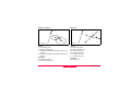
Cylinder Offset subapplication
Use [CYLNDER] to determine the coordinates of the
centre point of cylindrical objects and their radius.
Measure the horizontal angle to a point on the left
and on the right side of the object as well as the
distance to the object.
45
TPS400-5.0.1en
Procedure:
R
α
HzL
CYLINDRICAL OFFSET
Hz Left
:
120.4361
Hz Right
:
141.4435
V
:
99.4658
:
15.398
Hz
:
0.0000
PrismOffset:
0.030
P1
d
HzR
P0
TPS800_Z158
HZL:
HZR:
d:
Horizontal angle to a point on the left side of
the object
Horizontal angle to a point on the right side
of the object
Distance to the object in the middle between
HZL and HZR
HzLeft HzRight
1
2
3
4
TPS400-5.0.1en
46
ALL
g
g
g
m
g
m
EXIT
Enter the prism offset. This is the distance
between the centre of the prism and the surface
of the object to be measured. If the EDM mode
is RL, the value is set to zero automatically.
Use the vertical hair, aim at the left side of the
object, then press [HzLeft].
Use the vertical hair, aim at the right side of the
object, then press [HzRight].
Rotate the instrument accordingly such that the
S Hz, the deviation angle, is zero.
FNC Key
5
[ALL] Completes the measurement and displays
the results. That is the coordinates of the centre
point of the cylindrical object and its radius.
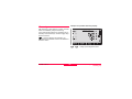
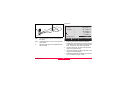
Height Transfer
Example:
Cylinder Offset Measure
PtID
:
POINTNUMBER
Description:
----North
:
638073,456 m
East
:
436102,123 m
Height
:
168,789 m
Radius
:
44,350 m
PREV
1)
2)
3)
4)
FNC Key
47
Reflector 1
Reflector 2
Reflector 3
Instrument
TPS400-5.0.1en
This function determines the height of the instrument from measurements to a maximum of 5 target
points, with known heights, in two faces.
With measurements to several targets, the improvement is indicated in the "delta" value.
Procedure:
1. Select known point and input reflector height.
2. After triggering the measurement with [ALL], the
calculated height H0 is displayed.
[AddPt]
Add another height of a known
point.
[FACE]
Measure to the same target in
second face.
3. [SET]
Save the changes and set the
station.
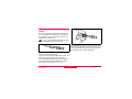
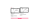
Hidden Point
Example:
3
2
1
1
2
3
E, N, H of Hidden Point
Rod Length
Distance R1-R2
The program allows measurements to a point that is
not directly visible, using a special hidden-point rod.
TPS400-5.0.1en
48
FNC Key
2. [All]
Starts measurement and proceeds
to the Result dialog.
3. Result is displayed.
Procedure:
1. Measure to first prism (P1).
[All]
Starts measurement and proceeds
to step 2.
[ROD]
Allows you to define the rod and the
EDM-Settings.
HIDDEN POINT RESULT
PtID
:
12
Desc.
:
GR
East
:
110.871 m
North
:
99.991 m
Heigth :
102.884 m
Rod Length
Total length of hidden-point rod.
Dist. R1-R2
Spacing between the centers of reflector R1 and
prism R2.
Meas. Tol
Limit for the difference between the given and
measured spacing of the reflectors. If the tolerance
value is exceeded, the program will issue a warning.
EDM-Mode
Changes the EDM-Mode.
FINISH
[NEW]
[FINISH]
NEW
Returns to step 1.
Returns to calling application.
Prism type
Changes the prism type.
Prism Const
Displays the prism constant.
FNC Key
49
TPS400-5.0.1en
Programs
[ ] Settings not made.
Application pre-settings
)
Find further information about individual
start-up programs on the subsequent pages !
These are programs that precede the application
programs and are used to set up and organize data
collection. They are displayed after selecting an
application. The user can select the start programs
individually.
Setting job
All data is saved in JOBS, like directories. Jobs
contain measurement data of different types (e.g.
measurements, codes, fixed points, stations,...) and
are individually manageable and can be readout,
edited or deleted separately.
[NEW]
Creating a new job.
[SET]
Setting the job and back to start-up
programs.
)
)
All subsequent recorded data is stored in
this job/directory.
If no job was defined and an application was
started or if in "Meas & Rec" [ALL] or [REC] was triggered, then the system automatically creates a new
job and names it "DEFAULT".
[ • ] Settings made.
TPS400-5.0.1en
50
Programs
Setting Station
Known Point
Each coordinate computation relates to the currently
set station.
At least plan coordinates (E, N) are required for the
station. The station height can be entered if
required. The coordinates can be entered either
manually or read from the internal memory.
1. Select a PtID stored in internal memory.
2. Input instrument height.
[OK]
Sets the station.
Set manually
1. [ENH]
Calls up manual point input
dialogue.
2. Input PtID and coordinates.
3. [SAVE]
Saves station coordinates.
Continues to the input of the instrument height.
4. [OK]
Sets the station.
)
If no station was set and no application
started and if in "Meas & Rec" [ALL] or [REC] was
activated, then the last station is set as the current
station.
Programs
51
TPS400-5.0.1en
Orientation
Method 2: with coordinates
With the orientation, Hz-direction can be input
manually or points with known coordinates can be
set.
To determine the orientation, a target with known
coordinates can also be used.
1.
As orientation with coordinates.
2. Input of the orientation point number and to
determine the point found.
3. To input and confirm the reflector height.
For determining the orientation a maximum of 5
target points with known coordinates can be used.
Method 1: Manual input
1.
To input a random Hz-orientation.
2. Input of Hz-direction, reflector height and PtID.
3. [ALL]
Triggers measurement and sets
orientation.
[REC]
Records Hz-direction and sets
orientation.
1) 1. Target point
2) 2. Target point
3) 3. Target point
TPS400-5.0.1en
52
Programs
Orientation coordinates can be either obtained from
the internal memory or entered manually.
The workflow is similar to Free Station workflow.
After each measurement you are asked wether to
proceed or not. Answering with yes brings you back
to the Measurement dialog, to take an additional
measurement. Answering with no brings you to the
Result dialog.
[COMPUTE]
Calculates and displays the orientation results.
[NextPt]
Input another backsight point.
1/I
Status indication; shows that first point was
measured in telescope position I.
1/I II First point measured in telescope pos. I and
II.
SHz:
After the first measurement the finding of
other target points (or the same point when
changing the telescope position) is easier
by setting the indicated angle difference
near to 0°00'00" by turning the instrument.
Programs
53
S
: Difference between horizontal distance to
target point computed from coordinates and
the measured distance.
Display of computed orientation
[OK]
Set computed Hz-orientation.
If more than one target point is measured then the
orientation is computed using the "least squares
method".
TPS400-5.0.1en
Displaying residuals
[RESID]
Display of residuals.
1) Actual
2) Design
SH:
Height correction
S
:
correction of the horizontal distance
SHz:
Correction of Hz-angle.
TPS400-5.0.1en
54
Programs
Useful information
•
•
•
If the orientation is only measured in telescope
position II the Hz-orientation is based on telescope position II. If measured only in telescope
position I or mixed the Hz-orientation is based
on telescope position I.
The prism height may not be changed during
measurements in the first and second telescope
position.
If a target point is measured several times in the
same telescope position the last valid measurement is used for the computation.
)
If no orientation was set and an application
was started resp. if in "Meas & Rec" [ALL] or [REC]
was triggered, then the current Hz-direction and Vangle are set as orientation.
Programs
55
TPS400-5.0.1en
[MENU]
Applications
1. Press the [MENU] fixed key.
2. Selecting the "Program" option.
Introduction
-
Applications are predefined programs, that cover a
wide spectrum of surveying duties and facilitate
daily work in the field.
3. Calling up applications and activating start programs.
[PAGE] Scroll to next page.
The following applications are available:
• Surveying
• Setting Out
• Tie Distance
• Area & Volume
• Free Station
• Reference Line
• Remote Height
• Construction
• Cogo (optional)
• Reference Plane (optional)
TPS400-5.0.1en
56
Programs
Surveying
With the program Surveying the measurement of an
unlimited number of points is supported. It is comparable to "Meas & Rec", but includes stationing, orientation and coding.
Two coding methods are available:
1. Simple coding = remark:
Input a code/remark in the relevant field. These
text is stored with the corresponding measurement with [ALL]. The code is not related to a
codelist, it is just a simple remark. A codelist on
the instrument is not necessary.
2. Expanded coding with codelist:
Press the [CODE] softkey. The code that was
input is searched for within the code list and it is
possible to add attributes to the code.
)
Codes are always stored as free codes
(Wi41-49), that means that codes are not directly
linked to a point. Point codes (Wi71-79) are not
available.
Procedure:
1. Input PtID, codes and the reflector height if
desired.
2. [ALL]
Triggers and records measurements.
[IndivPt]
Switches between individual and
current point number.
Programs
57
TPS400-5.0.1en
Stake out
Polar Stake out
This program calculates the required elements to
stakeout points from coordinates or manually
entered angles, horizontal distances and heights.
Setting out differences can be displayed continuously.
Normal indication of polar stake out offsets SHz,
S
,S
.
Setting out coordinates from memory
Procedure:
Select the point.
Starts measurement and calculation of
the stake-out elements.
[REC]
Saves the displayed values.
[B&D]
Input direction and Hz-distance of stake
out point.
[MANUAL] Enables simplified input of a point
without PtID and without the possibility
of storing the data of the point.
[DIST]
TPS400-5.0.1en
1) Actual
2) Point to be stake out
SHz:
Angle offset: positive if point to be setout is to the right of the actual direction.
S
:
Longitudinal offset: positive if point to be
stake out is further away.
S
:
Height offset: positive if point to be
stake out is higher than measured point.
58
Programs
Orthogonal Stake out
Cartesian Stake out
The position offset between measured point and
stake out point is indicated in a longitudinal and
transversal element.
Setting out is based on a coordinate system and the
offset is divided into a north and east element.
1) Actual
2) Point to be stake out
SL:
Longitudinal offset: positive if nominal
point further away.
ST:
Transversal offset, perpendicular to
line-of-sight: positive if nominal point is
to the right of measured point.
Programs
1) Actual
2) Point to be stake out
SE
Easting offset between stake out and actual
point.
SN
Northing offset between stake out and
actual point.
59
TPS400-5.0.1en
The following measurements sequences to
target points are possible:
1. Hz- and V-angles only (resection)
2. Distance and Hz- and V-angle (3 point
resection)
3. Hz- and V-angles to some point(s) and Hz- and
V-angle plus distance to other point(s).
Free Station
The application "Free Station" is used to determine
the instrument position from measurements to a
minimum of two known points and a maximum of
five known points.
The final computed results are Easting, Northing
and Height of the present instrument station,
including the instruments Hz-circle orientation.
Standard deviations and residuals for accuracy
assessments are provided.
For the calculation of the station, measured target
points can be re-measured, disabled and again
enabled.
TPS400-5.0.1en
60
Programs
Measuring facilities
Computation procedure
Single face I or II or dual face I + II measurements
are always possible. No specific point sequence or
specific face sequences are required.
Gross errors checks are made for dual face
measurements to ensure the same point(s) are
sighted with the other face.
The measuring procedure automatically determines
the method of evaluation, e.g. resection, 3 point
resection, etc.
If more than the minimum required measurements
are performed, the processing routine uses a least
squares adjustment to determine the plan position
and averages orientation and heights.
1. The original averaged face I and face II
measurements enter the computation process.
2. All measurements are treated with the same
accuracy, whether these are measured in single
or dual face.
3. Easting and northing is determined by the
method of least squares, including standard
deviation and improvements for Hz-direction
and horizontal distances.
4. The final height (H) is computed from averaged
height differences based on the original
measurements.
5. The Hz-circle orientation is computed with the
original averaged face I and face II measurements and the final computed plan position.
)
If a target point is measured several times in
the same telescope position the last valid measurement is used for computation.
Measurement restrictions:
• 2 face measurements
When measuring the same target in both faces,
the reflector height may not be altered when
changing the telescope position.
• Target points with 0.000 height
Target points with 0.000 height are discarded for
height processing. If target points have a valid
height of 0.000 m, use 0.001 m to enable it for
height processing.
Programs
61
TPS400-5.0.1en
Procedure:
Here you can enter a limit for the standard deviation
values. If your computed deviation exceeds the limit
a warning dialog appears, where you can decide
wether to proceed or not.
1. Input of the name of the station and the height of
the instrument.
2. Input of the target PtID and the reflector height.
Enables you to define an accuracy limit.
[ALL]
[REC]
TPS400-5.0.1en
62
Triggers angle and distance
measurement (3 point resection).
Saves Hz-direction and V-angle
(resection).
Programs
[AddPt]
[COMPUTE]
3/I
3/I II
Input another backsight point.
Calculates and displays the station
coordinates, if at least 2 points and
a distance were measured.
Indicates that the third point in telescope position I was measured.
Indicates that the third point in telescope positions I and II.
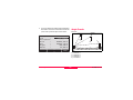
Results
Displays calculated station coordinates:
STATION COORDINATES
Station
hi
EO
NO
HO
PREV
[PREV]
[RESID]
[StdDev]
[OK]
Programs
63
:
:
:
:
:
RESID
100
1.500
100.506
100.040
99.999
StdDev
OK
Switches to measurement display,
to measure additional points.
Displays residuals.
Displays standard deviation.
Sets the displayed coordinates and
instrument height as new station.
TPS400-5.0.1en
)
This dialog shows the computed residuals:
Residual = Calculated value - Measured value
If the instrument height was set to 0.000 in
the setup screen, then the station height refers to
height of trunnion axis.
Displays standard deviations:
STATION
TARGET RESIDUALS 3/3
STANDARD-DEVITION
Std.Dev.EO :
Std.Dev.NO :
Std.Dev.HO :
Std.Dev.Ang:
PtID
Hz
0.027
0.013
0.000
+0.0121
PREV
PREV
[PREV]
OK
Std.Dev E0, N0, H0 Standard deviation of the
station coordinates
Std.Dev Ang
Standard deviation of the orientation
TPS400-5.0.1en
64
[Re-Meas]
[OK]
:
:
:
:
Re-Meas
300
-0.0096 g
-0.019 g
0.001 g
OK
Switches to measurement display,
to measure additional points.
Remeasures the displayed point.
Always sets the displayed coordinates and instrument height as new
station.
Programs
[Disable]/[Enable]
Excludes/includes the displayed
point from/in the calculations.
Recalculates the free station and
displays the station standard deviation. Press [PREV] to display the
new station coordinates.
[StdDev]
Displays standard deviation.
With the function keys, scroll
between the residuals of the individual backsight points.
Programs
65
TPS400-5.0.1en
Warnings / Messages
Important messages
Meaning
Selected point has no valid data !
This message occurs if the selected target point has no easting or northing
coordinate.
Max 5 points supported !
If 5 points have already been measured and another point is selected. The
system supports a maximum of 5 points.
Invalid data - no position computed !
The measurements may not allow final station coordinates (Eastings, Northings) to be computed.
Invalid data - no height computed !
Either the target height are invalid or insufficient measurements are available
to compute a final station height.
Insufficient space in job !
The present selected job is full and does not allow further storage.
Hz (I - II) > 0.9 deg, measure point again !
This error occurs if a point was measured in one face and the measurement
in the other face differs by more than 180° ±0.9° for the horizontal angle.
V (I - II) > 0.9 deg, measure point again !
This error occurs if a point was measured in one face and the measurement in
the other face differs by more than 360° - V ±0.9° for the vertical angle.
More points or distance required !
There is insufficient data measured to be able to compute a position. Either
there are not enough points used or not enough distances measured.
TPS400-5.0.1en
66
Programs
[ENH]
[LIST]
Reference Line
This program facilitates the easy stake out or
checking of lines for buildings, sections of road,
simple excavations, etc.
A reference line can be defined by referencing a
known base line. The reference line can be offset
either longitudinally, in parallel or vertically to the
base line, or be rotated around the first base point as
required.
Manually input coordinates.
Displays the list of available points.
Analogue procedure for the second base point.
Procedure:
1. Definition of the Base line:
The base line is fixed by two base points that can be
defined in three ways:
• Measured points
• Enter coordinates using keypad
• Select point from memory.
a) Measuring base points:
Input PtID and measure base points with [ALL]
or [DIST] / [REC].
b) Base points with coordinates:
[FIND]
Starts to search for the PtID
entered.
Programs
TPS800_Z36
1)
2)
3)
4)
67
1st base point
2nd base point
Base line
Reference line
TPS400-5.0.1en
2. Shifting/Rotating the Base line
The base line can be offset longitudinally, parallel
and vertically or rotated. This new line is called the
reference line. All measured data refers to the reference line.
BL
RL
BP2
Off:
L:
R:
Parallel offset
Longitudinal offset
Rotation parameter
Input of the parameters:
Use the navigation keys to select the
shifting and rotation parameters of the reference line.
R+
RP
L+
TPS800_Z37
BP:
BL:
RP:
RL:
BP1
Off+
Base point
Base line
Reference point
Reference line
TPS400-5.0.1en
68
Programs
3. Selecting the subapplication
REFERENCE LINE - MAIN 1/2
Length
:
14.872 m
Enter values to shift line:
Offset
:
1.000 m
Line
:
0.500 m
Height
:
0.900 m
Rotate
:
25.0000 g
NewBL
MEASURE
STAKE
[MEASURE]
[STAKE]
4. "Line & Offset" subapplication
SHIFT=0
The following entries are possible:
Offset+:
Parallel offset of the reference line
to the right, referred to the direction
of the base line (BP1-BP2).
Line+:
Longitudinal offset of the start point
(=reference point) of the reference
line in the direction of base point BP2.
Rotate+:
Rotation of the reference line clockwise around the reference point.
Height+:
Height offset; the reference line is
higher than the selected reference
height.
Programs
Starts the subapplication to measure
Line & Offset (see issue 4).
Starts the subapplication to stake
out (see issue 5).
69
The "Line & Offset" subapplication calculates from
measurements or coordinates longitudinal, parallel
offsets and height differences of the target point
relative to the reference line.
TPS400-5.0.1en
RL
PtID
:
hr
:
Offset:
Line :
:
MP
S
L+
SOff+
REFERENCE LINE
140
1.500
0.208
0.349
1.203
TPS800_Z38
1RP:
MP:
RL:
SL:
SOff:
DIST
1RP
IR
I
REC
The height of the first reference point is always used
as the reference height for the calculation of the
height differences (S
).
1st reference point
Measured point
Reference line
Longitudinal offset
Parallel offset
TPS400-5.0.1en
m
m
m
m
70
Programs
Example "relative to first reference point"
1RP
1BP
SH:
You can enter longitudinal, parallel and height
offsets for the target points to be set-out relative to
the reference line. The program calculates the difference between a measured point and the calculated
point. The program displays the orthogonal (SLine,
SOffset, S
) and the polar (SHz, S
,
S
) differences.
SH+
SH-
Hd+
1RP:
1BP:
RH:
Hd:
RH
5. "Stake out" subapplication
Procedure:
1. Input the orthogonal stake out elements.
2. [OK] Confirm entry and start calculation.
TPS800_Z39
1st reference point
1st base point
Reference height
Height difference between reference and
base point
Height difference from reference height
Programs
71
TPS400-5.0.1en
Display in "Stake out" measure mode:
Example "orthogonal stake out"
PtID
hr
Hz
RL
SL-
MP
ORTHOGONAL STAKEOUT 1/2
:
15
:
1.500 m
:
+0.200 g
IR
:
2.368 m
:
0.260 m
I
SP SO-
DIST
TPS800_Z40
1RP:
RL:
MP:
SP:
SL:
SOff:
1RP
Offset:
Line :
:
1st reference point
Reference line
Measured point
Stake out point
Longitudinal offset
Parallel offset
TPS400-5.0.1en
REC
2.040 m
1.203 m
0.260 m
The signs for the distance and angle differences are
correction values (required minus actual).
+SHz
Turn telescope clockwise to the stake
out point.
The stake out point is further away than
+S
the point measured.
72
Programs
+S
The stake out point is higher than the
measured point.
Tie Distance
The application Tie Distance computes slope
distance, horizontal distance, height difference and
azimuth of two target points measured online,
selected from the Memory or entered using the
Keypad.
The user can choose between two different
methods:
Polygonal (A-B, B-C)
Radial (A-B, A-C)
Warnings / Messages
Important
Messages
Meaning
Save via
RS232 !
Data output (system setting menu) via
RS232 interface is activated. To be able
to succesfully start reference line, the
"INTERN" setting must be enabled.
Base line too
short !
Base line is shorter than 1 cm. Choose
base points such that the horizontal
separation of both points is at least 1 cm.
Coordinates
invalid !
No coordinates or invalid coordinates for
a point. Ensure that a point used has at
least one Easting and one Northing coordinate.
Programs
Polygonal Method:
73
TPS400-5.0.1en
3. Result is displayed.
Brg
Azimuth between point1 and point2.
Radial Method:
Slope distance 1-2
S
Slope distance 1-3
S
S
Centre point
Grade
Slope distance 1-4
Softkeys - polygonal method:
[NewPt 1]
An additional missing line is
computed. Program starts again (at
point 1).
[NewPt 2]
Point 2 is set as starting point of a
new missing line. New point (Pt 2)
must be measured.
[RADIAL]
Switches to radial method.
In principal both methods are the same.
Any differences will be described.
Procedure:
1. Determine first target point.
[ALL]
Starts measurement to the target
point.
[FIND]
Searches internal memory for point
entered.
2. Determine second target point.
Proceed as with first target point.
TPS400-5.0.1en
Slope distance between point1 and
point2.
Horizontal distance between point1
and point2.
Height difference between point1
and point2.
Grade [%] between point1 and
point2.
74
Programs
Softkeys - radial method:
[NewPt 1]
Determine new central point.
[NewPt 2]
Determine new radial point.
[POLY]
Switch to polygonal method.
Programs
75
TPS400-5.0.1en
Area & Volume
The application program Area is used to compute
online areas of max. 50 points connected by
straights. The target points have to be measured,
selected from memory or entered via keyboard in
clockwise direction. The calculated area is projected
onto the horizontal plane (2D) or projected onto the
sloped reference plane defined by 3 points (3D).
Furthermore a volume with constant height can be
calculated in relation to the area (2D/3D).
P2
a
P3
b
P1
P4
P0
P0
P1
P2
a
b
TPS400-5.0.1en
76
Station
P3 Target point
Start point
P4 Target point
Target point
Perimeter, polygonal length from start point to
the current measured point.
Calculated area always closed to the start point
P1, projected onto the horizontal plane.
Programs
1. Determine area points
[ALL]
Starts the measurement to the
point.
[FIND] /
Searches for point in internal
[LIST]
memory.
[ENH]
For manual input of the coordinates.
[1PtBACK] Undo measurement or selection of
last point.
)
The area (2D) is calculated and displayed
once three points have been measured or selected.
The area (3D) is calculated once the sloped reference plane is defined by three points.
Programs
2. Results
[Def. 3D]
To define the sloped reference
plane by selecting or measuring
three points.
[VOLUME] To calculate a volume with constant
height. The height have to be
entered or measured.
[RESULT] To display and record additional
results (perimeter, volume).
)
)
Perimeter and volume are updated if
further area points are added.
The graphic shows always the area
projected onto the horizontal plane.
77
TPS400-5.0.1en
P0 Station
P1 Target point which defines the sloped reference
plane
P2 Target point which defines the sloped reference
plane
P3 Target point which defines the sloped reference
plane
P4 Target point
a Constant height
b Perimeter (3D), polygonal length from the start
point to the current measured point of the area
(3D)
c Area (3D), projected onto the sloped reference
plane
d Volume (3D) = a x c
e Perimeter (2D), polygonal length from the start
point to the current measured point of the area
(2D)
f Area (2D), projected onto the horizontal plane
g Volume (2D) = f x a
P2
P3
b
a
c
d
a
P0
P1
P4
g f
e
TPS800_Z101
TPS400-5.0.1en
78
Programs
Procedure:
1. Input PtID and reflector height
[ALL]
Starts measurement to base point
and continues to 2.
[hr?]
Starts the program that determines
an unknown reflector height.
2. Aim at inaccessible height point
[OK]
Saves the measured data.
[BASE]
Input and measurement of a new
base point.
Remote Height
Points directly above the base prism can be determined without a prism at the target point.
1)
2)
3)
4)
Remote point
Height diff.
Slope distance
Base point
Programs
79
TPS400-5.0.1en
Construction
This application allows to define a construction site
by combining set-up of the instrument along a
construction line, measuring and setting out points
in relation to the line.
PtID :
hr
:
:
Off:
:
After selecting the application you have two
options:
a) Defining a new construction site
or
b) Continue with previous site (skips set-up)
A11
1.500 m
7.225 m
10.194 m
-1.673 m
Procedure:
[ShiftLn]
Defining new site:
1. Measure line Start point [ALL], [DIST]+[REC]
2. Measure second line point [ALL], [DIST]+[REC]
[LAYOUT]
)
SLine
is positive:
Measured point is in direction from line start - to line
end point.
SOffset is positive:
Measured point is right of line.
SHeight is positive:
In case, you have entered coordinates by
ENH and measured to known points a plausibility
check informs you about the calculated line length,
the actual length and the difference.
As built check:
This dialog shows you the SLine, SOffset and
SHeight of a measured point in relation to the line.
TPS400-5.0.1en
Allows you to enter values for
shifting the line.
Switches to Layout-mode.
80
Programs
Measured point height is above line start point’s
height.
The graphics show you the position of the prism
related to the stake out point. Below, the exact
values are displayed, combined with arrows to show
the direction.
SLine is positive (arrow up):
Target point is further away than the measured
point.
)
The height of the line start point is always
used as the reference height!
Layout
Here you can search or enter points for staking out
related to the measured line.
SOffset
is positive (arrow right):
Target point is right of the measured point.
SHeight
is positive (arrow up):
Target point is higher than the measured point.
)
)
The height of the line start point is always
used as the reference height!
The graphics are scaled to give a better
overview. Therefore it’s possible that the station
point moves in the graphics.
[ShiftLn]
[AsBUILT]
Programs
)
Be aware that the line start point and the line
end point are measured in the previous coordinate
system. When staking out this points they appear in
the old system and appear as shifted.
Allows you to enter values for
shifting the line.
Switches to AsBuilt-mode.
81
TPS400-5.0.1en
)
During use of the application the previous
Orientation and Station parameters will be replaced
by the new calculated ones.
COGO (optional)
)
The application COGO can be started in
total 15 times for trial. Afterwards you have to enter
the license code.
COGO is an application program to perform coordinate geometry calculations such as:
• coordinates of points
• bearings between points
• distances between points
The COGO calculation methods are:
• Inverse & Traverse
• Intersections
• Offset
• Extension
Softkeys:
[MEAS]
Jumps to the Measurement dialog to
measure the point.
[Calc]
Starts the calculation, when all required
data is entered.
[STAKE] When the calculated point is displayed
you have the option to stake out this
point directly.
TPS400-5.0.1en
82
Programs
Traverse
Inverse & Traverse
Inverse
P4
d3
P2
d1
P3
d3
TPS800_Z87
P1
P1
Known
P1 Known point
a Direction from P1 to P2
d1 Distance between P1 and P2
d2 Positive offset to the right
d3 Negative offset to the left
Unknown
P2 COGO point without offset
P3 COGO point with positive offset
P4 COGO point with negative offset
Known
P1 First known point
P2 Second known point
Unknown
a Direction from P1 to P2
d1 Slope distance between P1 and P2
d2 Horizontal distance between P1 and P2
d3 Height difference between P1 and P2
Programs
d2
d1
d2
TPS800_Z86
P2
83
TPS400-5.0.1en
Bearing - Distance
Intersections
Bearing - Bearing
P4
r
1
P3
P3
P2
2
P1
TPS800_Z89
P1
P2
TPS800_Z88
Known
P1 First known point
P2 Second known point
a Direction from P1 to P3 and P4
r Radius, as defined by the distance from P2 to
P4 and P3
Unknown
P3 First COGO point
P4 Second COGO point
Known
P1 First known point
P2 Second known point
a1 Direction from P1 to P3
a2 Direction from P2 to P3
Unknown
P3 COGO point
TPS400-5.0.1en
84
Programs
By Points
Distance - Distance
P2
P4
P1
r1
b
P4
P5
r2
P3
P3
P2
TPS800_Z91
TPS800_Z90
P1
Known
P1 First known point
P2 Second known point
P3 Third known point
P4 Fourth known point
a Line from P1 to P2
b Line from P3 to P4
Unknown
P5 COGO point
Known
P1 First known point
P2 Second known point
r1 Radius, as defined by the distance from P1 to
P3 or P4
r2 Radius, as defined by the distance from P2 to
P3 or P4
Unknown
P3 First COGO point
P4 Second COGO point
Programs
a
85
TPS400-5.0.1en
Set Point by ...
Offset
Distance - Offset
P2
P2
b
P4
a
d2
d1
P3
P3
TPS800_Z92
TPS800_Z93
P1
Known
P1 Baseline start point
P2 Baseline end point
a Difference in length/abzissa (HD)
b Lateral deviation/ordinate (Offset)
Unknown
P3 Lateral point
Known
P1 Baseline start point
P2 Baseline end point
P3 Lateral point
Unknown
d1 Difference in length/abzissa (HD)
d2 Lateral deviation/ordinate (Offset)
P4 Base point
TPS400-5.0.1en
P1
86
Programs
Plane Offset
Extension
The "Extension" routine computes extend point from
base line.
P2
P5
P3
P1
d1
ΔL1
P2
P4
P3
P1
ΔL2
P4
TPS800_Z159
Known
P1
P3
SL1 or SL2
Unknown
P2, P4
Known
P1 Point 1 which defines plane
P2 Point 2 which defines plane
P3 Point 3 which defines plane
P4 Offset point
Unknown
P5 COGO point
d1 Offset
Programs
87
Baseline start point
Baseline end point
Distance
Extended point
TPS400-5.0.1en
•
Reference Plane (optional)
)
The application Reference Plane can be
trialed 15 times. Afterwards it is necessary to enter
the license code.
•
•
The Reference Plane application is used to measure
points relative to a reference plane. It can be used
for the following tasks:
• Measuring a point to calculate and store the
perpendicular offset to the plane.
• Calculating the perpendicular distance from the
intersection point to the local X- and Z-axis. The
intersection point is the footprint point of the
perpendicular vector from the measured point
through the defined plane.
• Viewing, storing and staking out the coordinates
of the intersection point.
The first point is the origin of a local coordinate
system.
The second point defines the direction of the
local Z-axis.
The third point defines the plane.
Z
Off+
a
P4
P2
P3
P1
X
Y
TPS800_Z147
A reference plane is created by measuring three
points on a plane. These three points define a local
coordinate system:
TPS400-5.0.1en
X
P5
Z
P1
P2
P3
88
b
First point, origin of local coordinate system
Second point
Third point
Programs
P4
P5
X
Z
Off+
SX
SZ
Measured point. This point is probably not
located on the plane.
Footprint point of the perpendicular vector
from P4 to the defined plane. This point is
definitely located on the defined plane.
X-axis of local coordinate system
Z-axis of local coordinate system
Perpendicular distance from P4 to the plane
Perpendicular distance from P5 to the local
Z-axis
Perpendicular distance from P5 to the local
X-axis
Programs
89
The perpendicular distance to the plane can be positive or negative:
Z
Off+
P1
X
OffY
TPS800_Z147a
TPS400-5.0.1en
[LIST]
[ENH]
Procedure
1. Measuring points defining the reference plane
Measure
Point 1
Point 2
Point 3
hr
ALL
PLANE 1/3
1st plane point !
:
A1
:
----IR
:
----:
1.500 m
:
-----.--- m
:
-----.--- m I
FIND
2. Measuring target point
Measure a target point as you usually survey points.
3. Results
PLANE RESULT 1/2
Int.PtID
X
Z
LIST
Input the name of the first point on the reference
plane and the height of the reflector. Measure the
point.
Repeat this for the second and the third point on the
reference plane.
[FIND]
Starts point search. Exact PtIDs can
be entered or the * wildcard-criteria
used.
TPS400-5.0.1en
Displays the list of available points.
Opens the coordinate input mode.
NewTgt
Int. PtID:
90
:
:
:
:
STAKE
104
1.380 m
4.500 m
2.000 m
NewPlan
EXIT
Point ID of the intersection point,
the perpendicular projection of the
target point on the plane.
Programs
Offset:
SX:
SZ:
[New Tgt]
[STAKE]
[New Plane]
[EXIT]
Calculated perpendicular distance
between target point and plane
(intersection point).
Perpendicular distance from the
intersection point to the local Z-axis.
Perpendicular distance from the
intersection point to the local X-axis.
The stake out point is higher than
the origin of the coordinate system.
To measure a new target point.
To display stake out values for the
intersection point.
To define a new reference plane.
Goes to the programs menu.
Coding
Codes contain information about recorded points.
With the help of coding, points can be assigned to a
particular group simplifying later processing.
More information on coding can be found under
"Data management".
GSI-coding
Code: Code name
Desc.: Additional remark
Info1: more, freely editable
...
information
Info8: lines
)
Codes are always stored as free codes
(Wi41-49), that means that codes are not directly
linked to a point. They are stored before or after the
measurement depending on the setting made.
Point codes (Wi71-79) are not available.
Programs
91
TPS400-5.0.1en
Warnings / Messages
Procedure:
Select code from a codelist or enter a new code:
[RECORD] The code is directly recorded without a
measurement with [ALL].
[OK]
The code is set. After a measurement
with [ALL] the code is recorded.
[AddList] Adds the entered code to the codelist.
Important
Messages
Extending / editing code
1. Call available code from code list.
2. Attributes can be overwritten freely.
Exceptions:
With the codelist editor of LGO/LGO-Tools a status
can be assigned to the attributes.
• Attributes with "fixed status" (see LGO/LGOTools) are write-protected. They cannot be overwritten or edited.
• For attributes with status "Mandatory" an input
or a confirmation is required.
• Attributes with status "Normal" can be edited
freely.
TPS400-5.0.1en
92
Meaning
Attrib. cannot be
changed !
Attribute with fixed status cannot
be changed.
No codelist available !
No codelist in memory. Manual
input for code and attributes are
called automatically.
Entry required !
Code missing. Extend input.
)
Individually entered code blocks are not
added to the code list.
Leica Geo Office Tools (LGO-Tools)
Codelists can be easily created and uploaded to the
instrument using the supplied "LGO-Tools" Software.
Programs
Settings
This menu enables extensive user-specific settings
in order to adapt the instrument to their own requirements.
•
•
•
Contrast
Setting the display contrast in 10% steps.
The % value increases rapidly. "--.--%"
appears on the display above 300%".
Trigger key
Configuration of the trigger key on side cover.
Off
Trigger key deactivated.
ALL
Trigger key with same function as
the [ALL]-key.
DIST
Trigger key with same function as
the [DIST]-key.
Tilt Correction
Off
Tilting compensation switched off.
1-axis
V-angles relate to the plumb line.
2-axis
V-angle refer to the plummet line and
the Hz-directions are corrected by the
standing axis tilt.
)
If the instrument is used on an unstable base (e.g.
shaking platform, ship, etc.) the compensator should
be switched off.
This avoids the compensator drifting out of it's
measuring range and interrupting the measuring
process by indicating an error.
USER Key
Configure the USER Key with a function from the
FNC-menu.
V-Setting
The "0"- orientation of the vertical circle can be
either selected for the zenith, the horizontal plane or
in %.
Settings
Zenith:
Zenith=0°; Horizon=90°
Horizon: Zenith=90°; Horizon=0°
V-(%):
45°=100%; Horizon=0°
)
The compensator setting remains active
even after the instrument is switched off.
93
TPS400-5.0.1en
Sector Beep
Off
Sector Beep switched off
On
Sector Beep sounds at right angles (0°,
90°, 180°, 270° or 0, 100, 200, 300 gon)
Example Sector Beep:
From 95.0 to 99.5 gon (or from 105.0 to 100.5 gon)
a "Fast beep" sounds whilst from 99.5 to 99.995 gon
(or from 100.5 to 100.005 gon) a "Permanent beep"
sounds.
1) No beep
2) Fast beep (interrupted)
3) Permanent beep
TPS400-5.0.1en
94
Settings
Beep
The beep is an acoustic signal after each key stroke.
Off
Beep switched off
Normal
Normal volume
Loud
Increased volume
Hz Incrementation
Right
Set right Hz for "Clockwise direction
measurement".
Left
Set left Hz for "Counter-clockwise direction measurement". "Counter-clockwise" directions are only displayed but
saved as "Clockwise direction".
Reticle Illumination
The reticle illumination is only switched on if the
display illumination is on.
Low
Low illumination
Medium
Medium illumination
High
High illumination
Settings
DSP Heater
On
Is automatically activated when the
display illumination is on and the instrument temperature is ≤ 5°C.
Language
The current loaded languages are shown.
Language choice
If two languages are loaded onto the instrument a
dialog to choose the language can be shown directly
after switching on the instrument.
On
The language dialog is shown as
startup dialog.
Off
The language dialog is not shown as
startup dialog.
Data Output
RS232
Data is recorded via the serial interface.
This setting in only required if an
external storage device is connected
and measurements are started at the
TPS with DIST/REC or ALL. This setting
is not required if the TPS is totally
controlled by a datalogger.
95
TPS400-5.0.1en
Intern
If option "Hz Collimation ON" is active, each
measured Hz-angle is corrected (depending on
V-angle).
For normal operation the Hz-collimation remains
switched on.
All data is recorded in the internal
memory.
GSI 8/16
Select GSI output format.
GSI 8:
81..00+12345678
GSI 16:
81..00+1234567890123456
)
More information on Hz-collimation can be
found under "Adjusments".
Auto-OFF
Enable
The instrument is switched off after 20
minutes without any action (= no key
pressed; V and Hz angle deviation
≤ ±3' / ±600cc).
Disable
The instrument is switched on permanently. Battery discharges quicker.
Sleep
Economy mode. Instrument is recovered by any key stroke.
Mask 1/2/3
Select GSI output mask.
Mask 1:
PtID, Hz, V, SD, ppm+mm, hr, hi
Mask 2:
PtID, Hz, V, SD, E, N, H, hr
Mask 3:
StationID, E, N, H, hi (Station)
StationID, Ori, E, N, H, hi (Station
Result)
PtID, E, N, H (Control)
PtID, Hz, V (Set Azimuth)
PtID, Hz, V, SD, ppm+mm, hr, E, N, H
(Measurement)
Angle Unit
°'"
(degree sexagesimal)
possible angle values: 0° to 359°59'59''
deg.dec
(degree decimal)
possible angle values: 0° to 359.999°
Hz Collimation
On
Hz Collimation is switched ON.
Off
Hz Collimation is switched OFF.
TPS400-5.0.1en
96
Settings
gon
mil
•
possible angle values: 0 gon to 399.999
gon
possible angle values: 0 to 6399.99mil
•
The setting of the angle units can be changed at any
time.
The actual displayed values are converted
according to the selected unit.
Distance Unit
meter
Meter
ft-in1/16
US-feet-Inch-1/16 inch
US-ft
US-feet
INT-ft
International feet
Min. Reading
The displayed angle format can be selected in three
steps.
• For 360°'":
0° 00' 01" / 0° 00' 05" / 0° 00' 10"
Always " are indicated.
• For 360°:
0.0001° / 0.0005° / 0.001°
• For gon:
0.0001 gon / 0.0005 gon / 0.001 gon
• For mil:
0.01 mil / 0.05 mil / 0.10 mil
Distance Digits
3
Displays distance with three decimals
4
Displays distance with four decimals
Temperature
°C
Degree Celsius
°F
Degree Fahrenheit
Pressure
mbar
hPa
mmHg
inHg
Input method
Here you can select the method to input alphanumeric characters.
Settings
Method 1
Standard method
Method 2
Advanced method
97
Millibar
Hecto Pascal
Millimeter mercury column
Inch mercury column
TPS400-5.0.1en
EDM Settings
The EDM-settings contain a detailed menu with
selection boxes.
TPS400-5.0.1en
EDM Mode
With TCR instruments different settings for
measurements with reflectorless (RL) and reflector
(IR) EDM mode are available.
Depending on selected measuring mode the selection prism types are different.
98
IR-Fine
Fine measuring mode for high
precision measurements with
prisms
(2mm + 2 ppm)
IR-Fast
Quick measuring mode with
higher measuring speed and
reduced accuracy
(5mm + 2 ppm)
IR-Track
Continuous distance
measuring
(5mm + 2 ppm)
IR-Tape
Distance measurement using
Retro targets
(5mm + 2 ppm)
EDM Settings
RL-Standard
For distance measurements
without prisms
(≤500m: 2mm + 2ppm
>500m: 4mm + 2ppm)
RL-Track
Continuous distance measurement without prisms
(5mm + 3 ppm)
RL-Prism
For distance measurements with
prisms
)
With the RL-EDM each object in the beam is
measured (possibly also branches, cars, etc.).
Prism type
Calling the function in the EDM settings.
Leica
Prisms
Constants
[mm]
Standard
prism (Round)
GPH1 +
GPR1
EDM Settings
360° prism
GRZ4
+23.1
360° Mini
prism
GRZ101
+30.0
Miniprism
GMP101/102
+17.5
JPMINI
+34.4 Mini prism
Reflective
targets
+34.4
USER
0.0
RL
99
is set at "Prismconst"
-- (-mm + 34.4; e.g.: mm = 14 ->
input = -14 + 34.4 = 20.4)
+34.4 Reflectorless
TPS400-5.0.1en
Prism Constant
Calling the function in the EDM settings.
Entry of a user specific prism constant. Input can
only be made in [mm].
Limit value: -999,9 mm to +999,9 mm
100 m (300 ft)
Laser Pointer
Off:
Visible laser beam is switched off.
On:
Visible laser beam for visualising the target
point is switched on.
Guide Light
The person at the prism can be guided by the
flashing lights directly to the line of sight. The light
points are visible up to a distance of 150 meters.
This is useful when setting out points.
6m
(20 ft)
6m
(20 ft)
1) Flashing red diode
2) Flashing yellow diode
Operat. range: 5 - 150 m (15 -500 ft)
Divergence:
12 m (40 ft) at 100 m (330 ft)
TPS400-5.0.1en
100
EDM Settings
[ATMOS]
Input of atmospheric parameters.
[SCALE]
Scale of projection.
Atmospheric Parameters (ppm):
Distance measurement is influenced directly by the
atmospheric conditions of the air in which distance
measurement are taken.
Scale factor:
Entering the scale of projection. Measured values
and coordinates are corrected with the PPM parameter.
[PPM=0]
Sets default parameters.
[PPM]
Input of individual scaling parameters.
EDM Settings
In order to take into consideration these influences
distance measurements are corrected using atmospheric correction parameters.
101
TPS400-5.0.1en
•
•
•
•
Ht. a. MSL
Height above sea level at instrument location.
Temperature
Air temperature at instrument location.
Pressure
Air pressure at instrument location.
Atmos PPM:
Calculated and indicated atmospheric PPM.
Signal
[SIGNAL]
Displays EDM signal strength (reflection
strength) in steps of 1%. Permits
optimal aiming at distant barely visible
targets.
TPS400-5.0.1en
102
EDM Settings
File Management
The File Manager contains all functions for entering,
editing and for checking data in the field.
File Management
Job
Jobs are a summary of data of different types, e.g.
fixed points, measurements, codes, results, etc.
The job definition consists of the input of job name
and user.
Additionally, the system generates time and date at
the time or creation.
Job search:
Scrolling through jobs.
[DELETE]
Deletes selected job.
[SET]
Sets the selected job.
[NEW]
Starts new job.
103
TPS400-5.0.1en
Fixpoints
Valid fixed points contain at least the PtID and the
coordinates (E, N) or (H).
[DELETE]
Deletes selected fixed point.
[FIND]
Starts point search. Exact PtIDs can
be entered or the * wildcard-criteria
used.
[NEW]
Opens input for PtID and coordinates.
Measurements
Measurement data available in the internal memory
can be searched and displayed or erased.
[FIND]
Starts point search dialogue.
[VIEW]
Displays all measurements.
[SAVE]
[VIEW]
[ATTRIB]
Save data.
Starts search dialogue.
Input of attributes.
Codes
To each code a description and a maximum of 8
attributes with up to 16 characters can be assigned.
Initialize Memory
Deletes jobs, single data areas of a job or all
data.
TPS400-5.0.1en
104
File Management
[DELETE]
[ALL]
)
Starts deleting process within the
selected area.
Deletes all data in memory. All data
will be lost !
Deleting the memory cannot be undone.
After confirming the message all data is deleted
permanently.
Memory Statistic
Displays job specific memory information such as:
• Number of stored fixpoints.
• Number of recorded data blocks (measured
points, codes, etc.).
• Number of free or not defined jobs.
File Management
105
TPS400-5.0.1en
Start-up sequence
Sets the screen the instrument starts in when
switched on. E.g. the electronic bubble can be
displayed at every start.
Procedure:
After confirming the dialogue of notification, the
"Meas & Rec" screen is displayed. A maximum of 16
of the next key presses are stored. The sequence is
ended with [ESC]. If the start sequence is activated,
the stored key presses are executed automatically
when the instrument is switched on.
)
The automatic start sequence has the same
effect as pressing the keys manually. Certain instrument settings can not be made in this way. "Relative
entries" such as automatically setting "IR-FINE"
upon switching on the instrument, are not possible.
[OK]
Stores current settings.
[RECORD] Defines the key presses that are
executed automatically upon start up.
TPS400-5.0.1en
106
Start-up sequence
Calibrations
Determining Line-of-sight error and V-Index
The calibration contains the determination of the
following instrument errors:
• Hz-collimation
• V-index (simultaneously electronic level)
For determining the Hz-collimation or the V-index it
is necessary to measure in both telescope positions.
The procedure can be started in any telescope position.
The user is guided clearly through the procedure. A
wrong determination of instrument error is thus eliminated.
The instruments are adjusted in the factory prior to
shipping.
Instrument errors can change with time and temperature.
Calibrations
)
These errors should be determined before
the instrument is used for the first time, before precision surveys, after long periods of transport, before
and after long periods of work, and if the temperature changes by more than 10°C (18°F).
Before determining the instrument
errors, level-up the instrument using the
electronic bubble. The instrument should
be secure and firm, and should be
protected from direct sunlight in order to avoid
thermal expansion on one side only.
107
TPS400-5.0.1en
Line-of-sight error (Hz-collimation)
V-Index (Vertical index error)
The line-of-sight error or collimation error (C) is the
deviation from the perpendicular between the tilting
axis and the line of sight.
The effect of the line-of-sight error to the Hz-angle
increases with the vertical angle.
For horizontal aimings the error of Hz equals the
line-of-sight error.
TPS400-5.0.1en
The vertical circle should read exactly 90° (100 gon)
when the line of sight is horizontal. Any deviation
from this figure is termed vertical index error (i).
By determining the vertical index error the electronic
level is adjusted automatically.
)
Procedures and conditions required to
correct line-of-sight and height index errors are the
same. Thus the procedure will only be described
once.
108
Calibrations
Hz-collimation
V-index
Display adjustment value:
Summarizes saved values.
4. Change telescope position and aim to the point
again.
For checking the horizontal aiming Hz and V are
displayed.
Procedure:
1. Level instrument with electronic bubble.
2. Aim at a point approximately 100m from the
instrument which is within 5° of the horizontal.
5. [ALL]: Starts measurement
6. Displays the old and new calculated values.
[SET]
Sets new calibration data.
[ESC]
Quits program without setting new
calibration data.
3. [ALL]: Trigger measurement.
Calibrations
109
TPS400-5.0.1en
Warnings / Messages
Important Messages
Meaning
Measures
V-Angle not suitable for
calibration (Check V-angle
or face) !
Aiming tolerance not met or telescope position/face not changed.
Aim on the target point with an accuracy of
min. 5 gon. The target point must be
approximately in the horizontal plane.
Confirmation of the message required.
Calibration result out of
tolerance. Previous values
retained !
Computed values out of tolerance.
Previous values retained.
Repeat measurements.
Confirmation of the message required.
Hz-Angle out of limit !
Hz-angle in second face/telescope pos.
deviates more than 5 gon from the target
point.
Aim on the target point with an accuracy of
min. 5 gon.
Confirmation of the message required.
Measurement Error. Try
again.
Measurement error appeared (e.g. instable
set up or period between measuring in telescope position I and II too long).
Repeat the process.
Confirmation of the message required.
TPS400-5.0.1en
110
Calibrations
COMM Parameters
For data transfer between PC and instrument the
communication parameters of the serial interface
RS232 must be set.
CR
Carriage return
Leica Standard setting
19200 Baud, 8 Databit, No Parity, 1 Stopbit, CR/LF
Interface plug connections:
Stopbits
Fixed setting 1.
Baudrate
Data transfer speed 2400, 4800, 9600, 19200
[bits / second]
Databits
7 Data transfer is realized with 7 databits. Is set
automatically if parity is "Even" or "Odd".
8 Data transfer is realized with 8 databits. Is set
automatically if parity is "None".
Parity
Even
Odd
None
Even parity
Odd parity
No parity (if data bit is set to 8)
Endmark
CRLF
Carriage return; line feed
COMM Parameters
1)
2)
3)
4)
5)
External battery
Not connected / inactive
GND
Data reception (TH_RXD)
Data transfer (TH_TXD)
TH ... Theodolite
111
TPS400-5.0.1en
Data Transfer
With this special function measured data can be transferred via the serial interface to a receiver (e.g. a
Laptop). Using this type of transfer the success of the
transfer is not checked.
Job:
Selection of job from which data should
be transferred.
Data:
Select the data range to be transferred
(measurements, fixed points)
Format:
Select output format. Select Leica-GSIformat, or your own format created in
the "Format Manager" and transfer to
the LGO/LGO-Tools.
[SEND]
Starts the transmission.
Example:
Within the "data" setting "MEASUREMENTS" a data
set could be shown as follows:
11....+00000D19 21..022+16641826
22..022+09635023 31..00+00006649
58..16+00000344 81..00+00003342
TPS400-5.0.1en
82..00-00005736 83..00+00000091
87..10+00001700
If the receiver is to slow in processing data
the data could be lost. With this type of data transfer
the instrument is not informed about the performance of the receiver (no protocol).
)
GSI-ID’s
11
21
22
25
31
32
33
41-49
51
58
81-83
84-86
87
88
112
PtID
Horizontal direction
Vertical angle
Orientation
Slope distance
Horizontal distance
Height difference
Codes and attributes
ppm [mm]
Prism constants
(E, N, H) Target point
(E, N, H) Stand point
Reflector height
Instrument height
Data Transfer
System Info
Displays helpful information and date / time are set.
•
Battery
Remaining battery power (e.g. 40%).
•
Instr.Temp.
Measured instrument temperature.
•
Date
Displays the current date.
•
Time
Displays current time.
[SW-Info]
The software of the instrument is
composed of different software packages. Depending on the package,
different versions are possible.
Op-System:
Operating System
App.-SW:
Applications, functions
and menu
Layout:
User displays
[DATE] Change date and format.
Format:
There are three display formats:
DD.MM.YYYY
MM.DD.YYYY
YYYY.MM.DDT
Date:
Input date
[TIME] Set time.
System Info
113
TPS400-5.0.1en
Instrument Protection with PIN
The instrument can be protected by a Personal
Identification Number. If the PIN protection is activated, the instrument will always prompt for a PIN
code entry after starting up. If a wrong PIN has been
typed in five times, a Personal UnblocKing code is
required which can be found on the instrument
delivery papers. If the PUK code entered is correct
then the old PIN code is set to default value "0" and
the PIN protection is deactivated.
by pressing [FNC] > Lock with PIN without switching
off the instrument
Procedure:
1. [MENU] > [PIN]
2. Activate PIN by setting <Use PIN Code>: On.
3. Enter your desired personal PIN Code (max. 6
character numeric) and accept with [OK].
)
Now the instrument is protected against
unauthorized use. After switching on the instrument
the PIN Code entry is necessary.
)
If the PIN protection is activated you can
furthermore lock the instrument from any application
TPS400-5.0.1en
114
Instrument Protection with
PIN
Care and Storage
In the field
Transport
When transporting or shipping the equipment
always use the original Leica Geosystems packaging (transport case and shipping cardboard).
)
After a longer period of storage or transport
of your product always check the field adjustment
parameters indicated in this manual before using the
product.
When transporting the equipment in the field,
always make sure to
• either carry the product in its original transport
case or,
• carry the tripod with its legs splayed across your
shoulder, keeping the attached product upright.
Care and Storage
115
TPS400-5.0.1en
Inside vehicle
Never transport the product loose inside the
vehicle.
The product can be damaged by blows and vibrations. It must always be transported in its case and
be properly secured.
Storage
Shipping
For shipping the product by rail, aircraft or ship use
the Leica Geosystems original packaging (transport
case or shipping cardboard) or another suitable
packaging securing the product against blows and
vibrations.
)
When storing the equipment, particularly in
summer and inside a vehicle, take the temperature
limits into account.
When storing the instrument inside a building also
use the transport case (if possible, in a safe place).
TPS400-5.0.1en
116
Care and Storage
Batteries
•
•
•
•
)
If the product becomes wet, leave it
unpacked. Wipe down, clean, and dry the product
(at not more than 40 °C/ 104°F), transport case,
foam inserts, and accessories. Pack up the equipment only when it is perfectly dry.
When using the product in the field always close the
transport case.
Care and Storage
•
•
117
Refer to Technical Data for information about
storage temperature range.
A storage temperature range of 0°C to +20°C /
+32°F to +68°F in a dry environment is recommended to minimize self-discharging of the
battery.
At the recommended storage temperature
range, batteries containing a 10% to 50%
charge can be stored for up to one year. After
this storage period the batteries must be
recharged.
Remove batteries from the product and the
charger before storing.
After storage recharge batteries (NiMH) before
using.
Protect batteries from damp and wetness. Wet
or damp batteries must be dried before storing
or use.
TPS400-5.0.1en
Cleaning
)
Fogging of prisms:
Reflector prisms that are cooler than the ambient
temperature tend to fog. It is not enough simply to
wipe them. Keep them for some time inside your
jacket or in the vehicle to allow them to adjust to the
ambient temperature.
)
Cables and plugs:
Keep plugs clean and dry. Blow away any dirt
lodged in the plugs of the connecting cables.
)
Objective, eyepiece and prisms:
Blow dust off lenses and prisms.
Never touch the glass with fingers.
Use only a clean, soft and lint-free cloth for
cleaning. If necessary, moisten the cloth with
pure alcohol.
Use no other liquids; these may attack polymer
components.
•
•
•
TPS400-5.0.1en
118
Care and Storage
Circular level
Checking and adjusting
Tripod
The connections between metal and timber components must always be firm and tight.
• Tighten the Allen screws (2) moderately.
• Tighten the articulated joints on the tripod head
(1) just enough to keep the tripod legs open
when you lift it off the ground.
Care and Storage
Level-up the instrument in advance with the electronic level. The bubble must be centered. If it
extends beyond the circle, use the Allen key
supplied to center it by turning the adjustment
screws.
After adjustment no screw must be loose.
119
TPS400-5.0.1en
Circular level on the tribrach
Laser plummet
The laser plummet is integrated into the vertical axis
of the instrument. Under normal circumstances
setting of the laser plummet is not necessary. If an
adjustment is necessary due to external influences
the instrument has to be returned to any Leica
service department.
Level the instrument and then remove it from the
tribrach. If the bubble is not centred, adjust it using the
adjusting pin.
Turning the adjustment screws:
• to the left: the bubble approaches the screw
• to the right: the bubble goes away from the
screw.
After adjustment no screw must be loose.
TPS400-5.0.1en
Checking by turning the instrument by 360°:
1. Install the instrument on the tripod approx. 1.5 m
above ground and level up.
2. Switch on laser plummet and mark the centre of
the red spot.
3. Turn instrument slowly by 360° and observe the
red laser spot.
Inspecting the laser plummet should be carried out
on a bright, smooth and horizontal surface (e.g. a
sheet of paper).
If the centre of the laser spot makes a clearly circular
movement or if the centre of the point is moving
away more than 3 mm from the first marked point an
adjustment is possibly necessary. Call your nearest
Leica service department.
120
Care and Storage
Depending on brightness and surface the size of the
laser spot can vary. At a distance of 1.5 m an
average value of 2.5 mm diameter must be estimated.
The maximum diameter of the circular movement
described by the centre of the laser point should not
exceed 3 mm at a distance of 1.5 m.
Care and Storage
121
TPS400-5.0.1en
Safety Directions
The following directions should enable the person
responsible for the product, and the person who
actually uses the equipment, to anticipate and avoid
operational hazards.
The person responsible for the product must ensure
that all users understand these directions and
adhere to them.
Intended Use
Permitted use
•
•
•
•
•
Measuring horizontal and vertical angles.
Measuring distances.
Recording measurements.
Computing by means of software.
Visualizing the aiming direction and vertical
axis.
Adverse use
•
•
•
•
•
•
•
TPS400-5.0.1en
122
Use of the product without instruction.
Use outside of the intended limits.
Disabling safety systems.
Removal of hazard notices.
Opening the product using tools (screwdriver,
etc.), unless this is specifically permitted for
certain functions.
Modification or conversion of the product.
Use after misappropriation.
Safety Directions
•
•
•
•
•
•
Use of products with obviously recognizable
damages or defects.
Use with accessories from other manufacturers
without the prior express approval of Leica
Geosystems.
Aiming directly into the sun.
Inadequate safeguards at the working site (e.g.
when measuring on roads, etc.).
Controlling machines, or controlling moving
objects or similar, with the integrated distancer
(visible laser).
Deliberate dazzling of third parties.
WARNING
Adverse use can lead to injury, malfunction,
and material damage. It is the task of the person
responsible for the equipment to inform the user
about hazards and how to counteract them. The
product is not to be operated until the user has been
instructed on how to work with it.
Safety Directions
Limits of Use
Environment
Suitable for use in an atmosphere appropriate for
permanent human habitation: not suitable for use in
aggressive or explosive environments.
DANGER
Local safety authorities and safety experts
must be contacted before working in hazardous
explosive areas, or in close proximity to electrical
installations or similar situations by the person in
charge of the product.
123
TPS400-5.0.1en
Responsibilities
Manufacturer of the product
Leica Geosystems AG, CH-9435 Heerbrugg, hereinafter referred to as Leica Geosystems, is responsible for supplying the product, including the user
manual and original accessories, in a completely
safe condition.
Manufacturers of non Leica Geosystems accessories
The manufacturers of non Leica Geosystems accessories for the product are responsible for developing, implementing and communicating safety
concepts for their products, and are also responsible
for the effectiveness of those safety concepts in
combination with the Leica Geosystems product.
TPS400-5.0.1en
Person in charge of the product
The person in charge of the product has the
following duties:
• To understand the safety instructions on the
product and the instructions in the user manual.
• To be familiar with local regulations relating to
safety and accident prevention.
• To inform Leica Geosystems immediately if the
product and the application becomes unsafe.
WARNING
The person responsible for the product must
ensure that it is used in accordance with the instructions. This person is also accountable for the
training and the deployment of personnel who use
the product and for the safety of the equipment in
use.
124
Safety Directions
Hazards of Use
WARNING
The absence of instruction, or the inadequate imparting of instruction, can lead to incorrect
or adverse use, and can give rise to accidents with
far-reaching human, material, financial and environmental consequences.
Precautions:
All users must follow the safety directions given by
the manufacturer and the directions of the person
responsible for the product.
CAUTION
Watch out for erroneous measurement
results if the product has been dropped or has been
misused, modified, stored for long periods or transported.
Precautions:
Periodically carry out test measurements and
perform the field adjustments indicated in the user
manual, particularly after the product has been
subjected to abnormal use and before and after
important measurements.
WARNING
Using a battery charger not recommended
by Leica Geosystems can destroy the batteries. This
can cause fire or explosions.
DANGER
Because of the risk of electrocution, it is very
dangerous to use poles and extensions in the
vicinity of electrical installations such as power
cables or electrical railways.
Precautions:
Only use chargers recommended by Leica
Geosystems to charge the batteries.
Precautions:
Keep at a safe distance from electrical installations. If
it is essential to work in this environment, first contact
Safety Directions
125
TPS400-5.0.1en
the safety authorities responsible for the electrical
installations and follow their instructions.
WARNING
If the product is used with accessories, for
example masts, staffs, poles, you may increase the
risk of being struck by lightning.
CAUTION
Be careful when pointing the product
towards the sun, because the telescope functions as
a magnifying glass and can injure your eyes and/or
cause damage inside the product.
Precautions:
Do not point the product directly at the sun.
TPS400-5.0.1en
Precautions:
The person responsible for the product must make
all users fully aware of the existing dangers.
Precautions:
Do not use the product in a thunderstorm.
WARNING
During dynamic applications, for example
stakeout procedures there is a danger of accidents
occurring if the user does not pay attention to the
environmental conditions around, for example
obstacles, excavations or traffic.
WARNING
Inadequate securing of the working site can
lead to dangerous situations, for example in traffic,
on building sites and at industrial installations.
Precautions:
Always ensure that the surveying site is adequately
secured. Adhere to the regulations governing safety
and accident prevention and road traffic.
WARNING
If computers intended for use indoors are
used in the field there is a danger of electric shock.
126
Safety Directions
Precautions:
Adhere to the instructions given by the computer
manufacturer with regard to field use in conjunction
with Leica Geosystems products.
Precautions:
Protect the batteries from mechanical influences
and high ambient temperatures. Do not drop or
immerse batteries into fluids.
CAUTION
During the transport, shipping or disposal of
batteries it is possible for inappropriate mechanical
influences to constitute a fire hazard.
Precautions:
Before shipping the product or disposing of it,
discharge the batteries by running the product until
they are flat.
When transporting or shipping batteries, the person
in charge of the product must ensure that the applicable national and international rules and regulations are observed. Before transportation or shipping contact your local passenger or freight transport company.
WARNING
High mechanical stress, high ambient
temperatures or immersion into fluids can cause
leakage, fire or explosions of the batteries.
Safety Directions
WARNING
If the product is improperly disposed of, the
following can happen:
• If polymer parts are burnt, poisonous gases are
produced which may impair health.
• If batteries are damaged or are heated strongly,
they can explode and cause poisoning, burning,
corrosion or environmental contamination.
• By disposing of the product irresponsibly you
may enable unauthorized persons to use it in
contravention of the regulations, exposing themselves and third parties to the risk of severe
injury and rendering the environment liable to
contamination.
• Improper disposal of silicone oil may cause
environmental contamination.
127
TPS400-5.0.1en
Precautions:
The product must not be disposed with
household waste. Dispose of the product
appropriately in accordance with the
national regulations in force in your
country. Always prevent access to the product by
unauthorized personnel.
Product specific treatment and waste management
information can be downloaded from the Leica
Geosystems home page at http://www.leicageosystems.com/treatment or received from your
Leica Geosystems dealer.
Avoid subjecting the product to mechanical stress.
CAUTION
Only Leica Geosystems authorized workshops are entitled to repair these products.
CAUTION
If the accessories used with the product are
not properly secured and the product is subjected to
mechanical shock, for example blows or falling, the
product may be damaged or people may sustain
injury.
Precautions:
When setting-up the product, make sure that the
accessories are correctly adapted, fitted, secured,
and locked in position.
TPS400-5.0.1en
128
Safety Directions
if used and operated as defined in this user manual
due to the low eye hazard level.
Laser classification
)
General
The following directions (in accordance with the
state of the art - international standard IEC 60825-1
(2007-03) and IEC TR 60825-14 (2004-02)) provide
instruction and training information to the person
responsible for the product and the person who
actually uses the equipment, to anticipate and avoid
operational hazards.
The person responsible for the product must ensure
that all users understand these directions and
adhere to them.
)
Products classified as laser class 1, class 2
and class 3R do not require:
• laser safety officer involvement,
• protective clothes and eye wear,
• special warning signs in the laser working
area
Safety Directions
Products classified as laser class 2 or class
3R may cause dazzle, flashblindness and afterimages, particularly under low ambient light conditions.
Distancer, Measurements with Reflectors (IR
mode)
The EDM module built into this product produces a
visible laser beam which emerges from the telescope objective.
The laser product described in this section is classified as laser class 1 in accordance with:
• IEC 60825-1 (2007-03): "Safety of laser
products"
Class 1 laser products are safe under reasonably
foreseeable conditions of operation and are not
harmful to the eyes provided that the products are
used and maintained in accordance with this user
manual.
129
TPS400-5.0.1en
Description
Value
Maximum average radiant power
0.33 mW
Pulse duration
800 ps
Pulse repetition frequency
100 MHz - 150 MHz
Wavelength
650 nm - 690 nm
TPS400-5.0.1en
130
Safety Directions
Labelling
Type: TC....
Art.No.: ......
Power: 12V/6V ---, 1A max
Leica Geosystems AG
CH-9435 Heerbrugg
Manufactured: ......
S.No.: ......
Complies with 21 CFR 1040.10 and 1040.11
except for deviations pursuant to Laser Notice
No.50, dated July 26,2001.
This device complies with part 15 of the FCC
Rules. Operation is subject to the following two
conditions: (1) This device may not cause harmful interference, and (2) this device must accept
any interference received, including inte
ference that may cause undesired operation.
Class 1 Laser Product
according to IEC 60825-1
( 2007-03 )
a) Laser beam exit
Safety Directions
131
TPS400-5.0.1en
Distancer, Measurements without Reflectors
(RL mode)
c) natural aversion behaviour for exposure to
bright light for the case of visible radiation.
The EDM module built into the product produces a
visible laser beam which emerges from the telescope objective.
Description
The laser product described in this section, is classified as laser class 3R in accordance with:
• IEC 60825-1 (2007-03): "Safety of laser
products"
Class 3R laser products:
Direct intrabeam viewing may be hazardous (lowlevel eye hazard), in particular for deliberate ocular
exposure. The risk of injury for laser class 3R products is limited because of:
a) unintentional exposure would rarely reflect
worst case conditions of (e.g.) beam alignment
with the pupil, worst case accommodation,
b) inherent safety margin in the maximum permissible exposure to laser radiation (MPE),
TPS400-5.0.1en
Value (R400/R1000)
Maximum average radiant power
5.00 mW
Pulse duration
800 ps
Pulse repetition frequency
100 MHz - 150 MHz
Wavelength
650 nm - 690 nm
Beam divergence
0.2 mrad x 0.3 mrad
NOHD (Nominal Ocular Hazard
Distance) @ 0.25s
80 m / 262 ft
WARNING
From a safety perspective class 3R laser
products should be treated as potentially hazardous.
Precautions:
Prevent direct eye exposure to the beam. Do not
direct the beam at other people.
132
Safety Directions
WARNING
Potential hazards are not only related to
direct beams but also to reflected beams aimed at
reflecting surfaces such as prisms, windows,
mirrors, metallic surfaces etc.
Precautions:
Do not aim at areas that are essentially reflective,
such as a mirror, or which could emit unwanted
reflections.
Do not look through or beside the optical sight at
prisms or reflecting objects when the laser is
switched on, in laser pointer or distance measurement mode. Aiming at prisms is only permitted when
looking through the telescope.
Safety Directions
133
TPS400-5.0.1en
Labelling
Laser Aperture
Laser Radiation
Avoid direct eye exposure
Class 3R Laser Product
according to IEC 60825-1
( 2007 - 03 )
Po ≤ 5.00 mW
λ = 650 - 690 nm
a) Laser beam
TPS400-5.0.1en
134
Safety Directions
Type: TC....
Art.No.: ......
Power: 12V/6V ---, 1A max
Leica Geosystems AG
CH-9435 Heerbrugg
Manufactured: ......
S.No.: ......
Complies with 21 CFR 1040.10 and 1040.11
except for deviations pursuant to Laser Notice
No.50, dated July 26,2001.
This device complies with part 15 of the FCC
Rules. Operation is subject to the following two
conditions: (1) This device may not cause harmful interference, and (2) this device must accept
any interference received, including inte
ference that may cause undesired operation.
Safety Directions
135
TPS400-5.0.1en
Electronic Guide Light EGL
The integrated Electronic Guide Light produces a
visible LED beam from the front side of the telescope. Depending on the type of telescope the EGL
may be designed differently.
)
The product described in this section, is
excluded from the scope of IEC 60825-1 (2007-03):
"Safety of laser products".
The product described in this section, is classified as
exempt group in accordance with IEC 62471 (200607) and does not pose any hazard provided that the
product is used and maintained in accordance with
this user manual.
TPS400-5.0.1en
a) LED beam red
b) LED beam yellow
136
Safety Directions
Laser plummet
The laser plummet built into the product produces a
visible red laser beam which emerges from the
bottom of the product.
The laser product described in this section, is classified as laser class 2 in accordance with:
• IEC 60825-1 (2007-03): "Safety of laser
products".
WARNING
From a safety perspective class 2 laser
products are not inherently safe for the eyes.
Precautions:
Avoid staring into the beam or pointing the beam at
other people.
Class 2 laser products:
These products are safe for momentary exposures
but can be hazardous for deliberate staring into the
beam.
Description
Value
Maximum average radiant power 1.00 mW
Pulse duration
c.w.
Pulse repetition frequency
c.w.
Wavelength
620 nm - 690 nm
Safety Directions
137
TPS400-5.0.1en
Labelling
Laser Radiation
Do not stare into beam
Class 2 Laser Product
according to IEC 60825-1
( 2007-03 )
P0 ≤ 1.00 mW
λ = 620 - 690 nm
a) Will be replaced by a Class 3R warning label if
applicable
TPS400-5.0.1en
138
Safety Directions
Electromagnetic Compatibility EMC
The term Electromagnetic Compatibility is taken to
mean the capability of the product to function
smoothly in an environment where electromagnetic
radiation and electrostatic discharges are present,
and without causing electromagnetic disturbances
to other equipment.
WARNING
Electromagnetic radiation can cause disturbances in other equipment.
1) Exit for laser beam
2) Laser beam
Although the product meet the strict regulations and
standards which are in force in this respect, Leica
Geosystems cannot completely exclude the possibility that other equipment may be disturbed.
CAUTION:
There is a risk that disturbances may be
caused in other equipment if the product is used in
conjunction with accessories from other manufacturers, for example field computers, personal
computers, two-way radios, non-standard cables or
external batteries.
Safety Directions
139
TPS400-5.0.1en
Precautions:
Use only the equipment and accessories recommended by Leica Geosystems. When combined
with the product, they meet the strict requirements
stipulated by the guidelines and standards. When
using computers and two-way radios, pay attention
to the information about electromagnetic acceptability provided by the manufacturer.
CAUTION
Disturbances caused by electromagnetic
radiation can result in erroneous measurements.
Although the product meets the strict regulations
and standards which are in force in this respect,
Leica Geosystems cannot completely exclude the
possibility that the product may be disturbed by very
intense electromagnetic radiation, for example, near
radio transmitters, two-way radios or diesel generators.
WARNING
If the product is operated with connecting
cables attached at only one of their two ends, for
example external supply cables, interface cables,
the permitted level of electromagnetic radiation may
be exceeded and the correct functioning of other
products may be impaired.
Precautions:
While the product is in use, connecting cables, for
example product to external battery, product to
computer, must be connected at both ends.
Precautions:
Check the plausibility of results obtained under
these conditions.
TPS400-5.0.1en
140
Safety Directions
•
FCC Statement (Applicable in U.S.)
WARNING
This equipment has been tested and found
to comply with the limits for a Class B digital device,
pursuant to part 15 of the FCC Rules.
These limits are designed to provide reasonable
protection against harmful interference in a residential installation.
This equipment generates, uses and can radiate
frequency energy and, if not installed and used in
accordance with the instructions, may cause
harmful interference to radio communications.
However, there is no guarantee that interference will
not occur in a particular installation.
•
•
Increase the separation between the equipment
and receiver.
Connect the equipment into an outlet on a circuit
different from that to which the receiver is
connected.
Consult the dealer or an experienced radio/TV
technician for help.
WARNING
Changes or modifications not expressly
approved by Leica Geosystems for compliance
could void the user's authority to operate the equipment.
If this equipment does cause harmful interference to
radio or television reception, which can be determined by turning the equipment off and on, the user
is encouraged to try to correct the interference by
one or more of the following measures:
• Reorient or relocate the receiving antenna.
Safety Directions
141
TPS400-5.0.1en
Labelling:
........
..........: ......
............. ..........
.......................
.......................
....................
....................
....................
........: ......
This device complies with part 15 of the FCC
Rules. Operation is subject to the following two
conditions: (1) This device may not cause harmful interference, and (2) this device must accept
any interference received, including inte
ference that may cause undesired operation.
TPS400-5.0.1en
142
Safety Directions
Technical Data
Telescope
• Transit fully
• Magnification:............................................. 30x
• Image: ................................................... upright
• Free Objective aperture: ....................... 40 mm
• Shortest focussing distance: ........1.7 m (5.6 ft)
• Focusing: ................................................... fine
• Field of view: ..............................1°30' (1.7gon)
• Telescope field of view at 100m.............. 2.6 m
Angle measurement
• absolute, continuous,
• Updates each 0.3 seconds
• Units selectable
360° sexagesimal, 400gon,
360° decimal, 6400 mil, V%, ±V
• Accuracy standard deviation Hz, V
(acc. to ISO 17123-3)
TC(R)403 ...................................... 3" (1 mgon)
TC(R)405 ................................... 5" (1.5 mgon)
TC(R)407 ...................................... 7" (2 mgon)
Technical Data
Display resolution
gon ........................................................ 0.0005
360d ...................................................... 0.0005
360s ..............................................................1"
mil ............................................................. 0.01
Level sensitivity
• Circular level: ...................................... 6'/2 mm
Compensator
• 2-axis-oil compensator
• Setting range ............................. ±4' (0.07 gon)
• Setting accuracy ..............................................
TC(R)407 ................................... 2" (0.7 mgon)
TC(R)405 ................................ 1.5" (0.5 mgon)
TC(R)403 ................................... 1" (0.3 mgon)
143
TPS400-5.0.1en
Laser plummet
• Location: ..............in vertical axis of instrument
• Accuracy: ..................................Deviation from
.............................................plumbline 1.5 mm
............................................ (2 sigma) at 1.5 m
............................................. instrument height
• Diameter of laser point............. 2.5 mm / 1.5 m
Keyboard
• Tilt angle: ....................................................70°
• optional 2nd keyboard
Display
• Backlit
• Heatable................................... (Temp. < -5°C)
• LCD:........................................ 280 x 160 Pixel
• 8 lines with 31 characters each
Type of tribrach
• Tribrach removable GDF111
Thread diam.:.............................................5/8"
.........................................(DIN 18720 / BS 84)
TPS400-5.0.1en
Dimensions
• Instrument: .......................................................
Height (including tribrach and carrying handle):
- with tribrach GDF111.....................................
............................................... 360 mm ± 5 mm
Width:.................................................. 203 mm
Length: ................................................ 151 mm
• Case: .................................. 468x254x355 mm
............................................................ (LxBxH)
Weight
(including battery and tribrach)
• with tribrach GDF111 ............................. 5,2 kg
Tilting axis height
• without tribrach ................................... 196 mm
• with tribrach GDF111 ............. 240 mm ± 5 mm
Power supply
• Battery GEB111: ......................................NiMh
Voltage:........................................................6V
Capacity: ..........................................2100 mAh
• Battery GEB121: ......................................NiMh
Voltage:........................................................6V
Capacity: ..........................................4200 mAh
144
Technical Data
•
Recording
• RS232 interface ......................................... Yes
• Internal Memory ........................................ Yes
Total capacity....................................... 768 KB
.............................. ≈ 12500 measurements or
............................................. ≈ 18000 fixpoints
External supply
(via serial interface)
............................. If an external cable is used,
........................ then the voltage range must lie
..................................between 11.5V and 14V.
No. of measurements (angle + distance)
• GEB111: ..................................... approx. 4000
• GEB121: ..................................... approx. 9000
Temperature range
Operating
temperature
Type
Storage
temperature
TPS400
-20°C to +50°C / -40°C to +70°C /
-4°F to +122°F -40°F to +158°F
Battery internal
-20°C to +50°C /
-4°F to +131°F
-40°C to +55°C /
-40°F to +131°F
Automatic corrections
• Line-of-sight error.......................................Yes
• Vertical-index error.....................................Yes
• Earth curvature ..........................................Yes
• Refraction...................................................Yes
• Tilt correction .............................................Yes
Technical Data
145
TPS400-5.0.1en
Distance measurement (IR: Reflector mode)
Principle:
Type:
Carrier wave:
Measuring system:
•
•
Phase measurement
Coaxial, visible red laser
Class 1
658 nm
System analyser basis
100 MHz - 150 MHz
EDM type ..............................................coaxial
Display (least count) ............................... 1 mm
EDM
measuring
program
Accuracy*
(Standard deviation
acc. to ISO 17123-4)
Time per
measurement
IR_Fine
2 mm + 2 ppm
typ. 2.4 s
IR_Fast
5 mm + 2 ppm
typ. 0.8 s
Tracking
5 mm + 2 ppm
typ. < 0.15 s
IR Tape
5 mm + 2 ppm
typ. 2.4 s
Range: (normal and rapid measurement)
Standard 3 prisms
prism
(GPH3)
360°
reflector
1800 m 2300 m
800 m
1 (6000 ft) (7500 ft) (2600 ft)
3000 m 4500 m 1500 m
2 (10000
ft) (14700 ft) (5000 ft)
3500
m
5400 m 2000 m
3
(12000 ft) (17700 ft) (7000 ft)
1)
2)
3)
Tape
60mm x
60mm
150 m
(500 ft)
250 m
(800 ft)
250 m
(800 ft)
Mini
prism
360° Mini
prism
800 m
(2600 ft)
1200 m
(4000 ft)
2000 m
(7000 ft)
450 m
(1500 ft)
800 m
(2600 ft)
1000 m
(3500 ft)
Strong haze, visibility 5km; or strong sunlight, severe
heat shimmer
Light haze, visibility about 20km; or moderate sunlight,
slight heat shimmer
Overcast, no haze, visibility about 40km; no heat
shimmer
* Beam interruptions, severe heat shimmer and
moving objects within the beam path can result in
deviations of the specified accuracy.
TPS400-5.0.1en
146
Technical Data
Distance measurement (RL: Reflectorless mode)
Measuring
system:
Type:
Carrier wave:
Power: Range (without reflector)
System analyser basis 100 MHz 150 MHz
Coaxial, visible red laser Class 3R
658 nm
Distance measurement (without reflector)
• Range of measurement:
Power..................................... 1.5 m to >400 m
Ultra ..................................... 1.5 m to >1000 m
• Display unambiguous:........................ to 760 m
• Prism constant (additive constant):. + 34.4 mm
Atmospheric
conditions
No reflector
(white target)*
No reflector
(grey, albedo 0.25)
4
200 m (600 ft)
100 m (330 ft)
5
300 m (990 ft)
150 m (490 ft)
6
>400 m (>1310 ft)
>200 m (>660 ft)
Ultra: Range (without reflector)
Atmospheric
conditions
No reflector
(white target)*
No reflector
(grey, albedo 0.25)
4
600 m (1970 ft)
300 m (990 ft)
5
800 m (2630 ft)
400 m (1310 ft)
6
>1000 m (>3280 ft)
>500 m (>1640 ft)
*
Kodak Grey Card used with exposure meter for
reflected light
4) Object in strong sunlight, severe heat shimmer
5) Object in shade, or sky overcast
6) Day, night and twilight
Technical Data
147
TPS400-5.0.1en
EDM
measuring
program
Accuracy
Time per
measurement
0 - 500 m
2 mm + 2 ppm
> 500 m
4 mm + 2 ppm
typ. 3 - 6 s
max. 12 s
Tracking***
5 mm + 3 ppm
typ. 0.25 s
Distance measurement RL-prism (with reflector)
• Range of measurement: .......... from 1000m up
• Display unambiguous: ....................... to 12 km
Standard**
Ultra & Power: Range (with reflector)
Atmospheric
conditions
** Standard deviation acc. to ISO 17123-4, beam
interruptions, severe heat shimmer and moving
objects within the beam path can result in deviations
of the specified accuracy.
*** Accuracy and measure time depend on atmospheric conditions, target object and observation
situation.
TPS400-5.0.1en
Standardprism
Reflector tape
60 x 60
1
2200 m (7200 ft)
600 m (2000 ft)
2
7500 m (24600 ft)
1000 m (3300 ft)
3
> 10000 m (33000 ft)
1300 m (4200 ft)
1) Strong haze, visibility 5km; or strong sunlight,
severe heat shimmer
2) Light haze, visibility about 20km; or moderate
sunlight, slight heat shimmer
3) Overcast, no haze, visibility about 40km; no
heat shimmer
148
Technical Data
Atmospheric correction
The distance displayed is correct only if the scale
correction in ppm (mm/km) which has been entered
corresponds to the atmospheric conditions
prevailing at the time of the measurement.
The atmospheric correction takes air pressure and
air temperature into account.
For utmost precision in distance measurements,
atmospheric correction must be determined with
1 ppm accuracy, air temperature to 1°C and air pressure to 3mb accuracy.
Technical Data
149
TPS400-5.0.1en
Atmospheric correction in ppm with °C, mb, H
(metres) at 60% relative humidity
TPS400-5.0.1en
Atmospheric correction in ppm with °F, inch Hg,
H (feet) at 60% relative humidity
150
Technical Data
Reduction formulae
The instrument calculates slope distance, horizontal
distance and height difference in accordance with
the following formula. Earth curvature and mean
refraction coefficient (k = 0.13) are taken into
account automatically. The calculated horizontal
distance relates to the station height, not to the
reflector height.
= D0 · (1 + ppm · 10-6) + mm
=
D0
displayed slope distance [m]
=
uncorrected distance [m]
ppm =
scale correction [mm/km]
mm
prism constant [mm]
=
=Y-A*X*Y
Height measurement
1) Mean sea level
2) Instrument
3) Reflector
Technical Data
= X + B * Y2
151
=
horizontal distance [m]
=
height difference [m]
TPS400-5.0.1en
· |sin ζ |
Y
=
X
=
ζ
=
A
=
=
1.47 · 10-7 [m-1]
B
=
=
6.83 · 10-8 [m-1]
k
=
0.13
R
=
6.37 · 106 m
· cos ζ
vertical-circle reading
TPS400-5.0.1en
152
Technical Data
International Limited Warranty, Software License Agreement
International Limited Warranty
Software License Agreement
This product is subject to the terms and conditions
set out in the International Limited Warranty which
you can download from the Leica Geosystems
home page at http://www.leica-geosystems.com/
international warranty or collect from your Leica
Geosystems distributor.
This product contains software that is preinstalled
on the product, or that is supplied to you on a data
carrier medium, or that can be downloaded by you
online pursuant to prior authorization from Leica
Geosystems. Such software is protected by copyright and other laws and its use is defined and regulated by the Leica Geosystems Software License
Agreement, which covers aspects such as, but not
limited to, Scope of the License, Warranty, Intellectual Property Rights, Limitation of Liability, Exclusion
of other Assurances, Governing Law and Place of
Jurisdiction. Please make sure, that at any time you
fully comply with the terms and conditions of the
Leica Geosystems Software License Agreement.
The foregoing warranty is exclusive and is in lieu of
all other warranties, terms or conditions, express or
implied, either in fact or by operation of law, statutory
or otherwise, including warranties, terms or conditions of merchantability, fitness for a particular
purpose, satisfactory quality and non-infringement,
all of which are expressly disclaimed.
Such agreement is provided together with all products and can also be referred to and downloaded at
the Leica Geosystems home page at
International Limited Warranty, Software License
153
TPS400-5.0.1en
http://www.leica-geosystems.com/swlicense or
collected from your Leica Geosystems distributor.
You must not install or use the software unless you
have read and accepted the terms and conditions of
the Leica Geosystems Software License Agreement. Installation or use of the software or any part
thereof, is deemed to be an acceptance of all the
terms and conditions of such license agreement. If
you do not agree to all or some of the terms of such
license agreement, you may not download, install or
use the software and you must return the unused
software together with its accompanying documentation and the purchase receipt to the dealer from
whom you purchased the product within ten (10)
days of purchase to obtain a full refund of the
purchase price.
TPS400-5.0.1en
154
International Limited Warranty, Software License
Index
A
Abbreviations ..................................................... 12
Additional characters ......................................... 39
Adverse uses ................................................... 122
Alphanumerical input ......................................... 38
Angle measurement ........................................ 143
Angle Unit .......................................................... 96
Application default settings ................................ 50
Applications ....................................................... 56
Area ................................................................... 76
ATMOS ............................................................ 101
Atmospheric correction .................................... 149
Automatic corrections ...................................... 145
Auto-OFF ........................................................... 96
Azimuth ............................................................. 74
B
Base Line .................................................... 67, 68
Battery ............................................................. 113
Battery capacity ................................................. 24
Index
Baudrate .......................................................... 111
Beep .................................................................. 95
Brg ..................................................................... 74
C
Calibration ....................................................... 107
Care and Storage ............................................ 115
Cartesian Stake out ........................................... 59
Character set ..................................................... 39
Checking and adjusting ................................... 119
Circular level ................................................... 119
Cleaning .......................................................... 118
Codelist ........................................................... 104
Codelist Manager .............................................. 15
COGO ......................................................... 56, 82
Collimation axis ................................................. 12
Communication parameters ............................ 111
Compensator ............................................. 24, 143
Computation procedure ..................................... 61
Construction application .................................... 80
155
TPS400-5.0.1en
Contrast ............................................................. 93
Coordinate Editor .............................................. 15
Cylinder Offset ................................................... 45
D
Data Exchange Manager ................................... 15
Data Output ....................................................... 95
Data Transfer .................................................. 112
Databits ........................................................... 111
Date ................................................................. 113
Delete Last Record ............................................ 44
Dimensions ...................................................... 144
Display ............................................................. 144
Distance Digits .................................................. 97
Distance measurement ............. 20, 146, 147, 148
Distance Unit ..................................................... 97
DSP Heater ....................................................... 95
E
Edit mode .......................................................... 36
EDM Mode ........................................................ 98
EDM Settings .................................................... 98
EDM type ........................................................... 24
TPS400-5.0.1en
EGL ................................................................. 100
Electromagnetic acceptability .......................... 139
Electronic Guide Light EGL ............................. 136
Electronic level ............................................ 32, 33
Endmark .......................................................... 111
Erasing characters ............................................ 36
ESC ................................................................... 19
Extending / editing code .................................... 92
F
FCC Statement ............................................... 141
File Management ............................................ 103
Fixed keys ......................................................... 19
Fixpoints .......................................................... 104
FNC ............................................................. 19, 43
Free Station ....................................................... 60
Free-Coding ...................................................... 43
Function keys .................................................... 18
G
GSI 8/16 ............................................................ 96
GSI output format .............................................. 96
GSI output mask ............................................... 96
156
Index
GSI-coding ........................................................ 91
GSI-ID’s ........................................................... 112
Guide Light ...................................................... 100
H
Hazards of use ................................................ 125
Height determination of remote points .............. 79
Height transfer ................................................... 47
Hidden Point ...................................................... 48
Horizontal circle ................................................. 12
Horizontal direction ............................................ 12
Hz Collimation ................................................... 96
Hz Incrementation ............................................. 95
I
Initialize Memory ............................................. 104
Input method ..................................................... 97
Input mode - method 1 ...................................... 35
Inserting / Replacing Battery ............................. 27
Inserting characters ........................................... 37
Instr.Temp. ...................................................... 113
Instrument Protection ...................................... 114
Interface .......................................................... 111
Index
Interface plug connections .............................. 111
Intersections ...................................................... 84
Bearing - Bearing .............................................. 84
Bearing - Distance ............................................. 84
By Points ........................................................... 85
Distance - Distance ........................................... 85
Inverse .............................................................. 83
IR ....................................................................... 43
IR/ RL Toggle .................................................... 43
IR-Fast .............................................................. 98
IR-Fine .............................................................. 98
IR-Tape ............................................................. 98
IR-Track ............................................................ 98
J
Job .................................................................. 103
JPMINI .............................................................. 99
K
Keyboard ......................................................... 144
Keypad .............................................................. 18
Known Point ...................................................... 51
157
TPS400-5.0.1en
L
Labelling .......................................... 131, 138, 141
Language .......................................................... 95
Language choice ......................................... 19, 95
Laser Classification ................................. 129, 132
Laser classification .......................................... 129
Laser intensity ................................................... 34
Laser plummet ................................. 120, 137, 144
Laser Pointer ................................................... 100
Laserpointer ...................................................... 43
Leica Geo Office Tools ................................ 15, 92
Level .................................................................. 33
Level sensitivity ............................................... 143
Level/Plummet ................................................... 43
LGO-Tools ......................................................... 92
Light On /Off ...................................................... 43
Limits of use .................................................... 123
Line of sight ....................................................... 12
Line-of-sight error ...................................... 13, 107
M
Mask 1/2/3 ......................................................... 96
Measurements ........................................... 60, 104
TPS400-5.0.1en
Measuring ......................................................... 42
Measuring facilities ............................................ 61
Memory ........................................................... 104
MENU .......................................................... 19, 25
Menu tree .......................................................... 25
Min. Reading ..................................................... 97
N
Navigation keys ................................................. 18
No. of measurements ...................................... 145
Numerical input ................................................. 38
O
Offset ........................................................... 24, 86
Distance - Offset ............................................... 86
Extention ........................................................... 87
Plane Offset ...................................................... 87
Set Point by ... ................................................... 86
Orientation ......................................................... 52
Orthogonal Setout ............................................. 71
Orthogonal Stake out ........................................ 59
P
PAGE ................................................................ 19
158
Index
Parity ............................................................... 111
Permitted uses ................................................ 122
PIN ............................................................ 44, 114
Plane Offset ....................................................... 87
Plumb line .......................................................... 13
Pointsearch ....................................................... 40
Polar Stake out .................................................. 58
Polygonal Method .............................................. 73
Positioning ......................................................... 34
Power Supply ............................................ 17, 144
PPM ................................................................. 101
Pressure ............................................................ 97
Prism Constant ................................................ 100
Prism type ......................................................... 99
Programs ........................................................... 50
PUK code ........................................................ 114
R
Radial Method ................................................... 74
Range .............................................. 146, 147, 148
Recording ........................................................ 145
Reduction formulae ......................................... 151
Reference Line .................................................. 67
Index
Reference Plane ......................................... 56, 88
Reflective targets .............................................. 99
Responsibilities ............................................... 124
Reticle ............................................................... 13
Reticle Illumin. ................................................... 95
RL ...................................................................... 43
RL-Prism ........................................................... 99
RL-Standard ...................................................... 99
RL-Track ........................................................... 99
Rod Length ........................................................ 49
RS232 ............................................................... 95
S
Safety Directions ............................................. 122
SCALE ............................................................ 101
Sector Beep ...................................................... 94
Set manually ..................................................... 51
Setting job ......................................................... 50
Setting Station ................................................... 51
Settings ............................................................. 93
Signal .............................................................. 102
Signs ................................................................. 39
Softkeys ............................................................ 23
159
TPS400-5.0.1en
Software Upload ................................................ 15
Stake out ........................................................... 58
Standard prism .................................................. 99
Standing axis ..................................................... 12
Standing axis inclination .................................... 13
Start programs ................................................... 50
Start-up sequence ........................................... 106
Statistics .......................................................... 105
Stopbits ........................................................... 111
Storage ............................................................ 116
Surveying .......................................................... 57
Symbols ............................................................. 24
System Info ..................................................... 113
T
Target Offset ..................................................... 44
Technical Data ................................................ 143
Technical terms ................................................. 12
Telescope ........................................................ 143
Temperature ...................................................... 97
Temperature range .......................................... 145
Tie Distance ...................................................... 73
Tilt Correction .................................................... 93
TPS400-5.0.1en
Tilting axis ......................................................... 12
Tilting axis height ............................................ 144
Time ................................................................ 113
Transport ......................................................... 115
Traverse ............................................................ 83
Tribrach ................................................... 120, 144
Trigger key .................................................. 19, 93
Tripod .................................................. 30, 32, 119
U
Units .................................................................. 43
USER ................................................................ 19
USER Key ......................................................... 93
V
Vertical angle .................................................... 12
Vertical circle ..................................................... 12
V-Index ...................................................... 13, 107
Volume ........................................................ 56, 76
V-Setting ........................................................... 93
W
Weight ............................................................. 144
Wildcard search ................................................ 41
160
Index
Z
Zenith ................................................................ 13
Zenith angle ....................................................... 12
Index
161
TPS400-5.0.1en
Leica Geosystems AG, Heerbrugg, Switzerland, has been
certified as being equipped with a quality system which
meets the International Standards of Quality Management
and Quality Systems (ISO standard 9001) and
Environmental Management Systems (ISO standard
14001).
Ask your local Leica dealer for more information about our TQM program.
Leica Geosystems AG
Heinrich-Wild-Strasse
CH-9435 Heerbrugg
Switzerland
Phone +41 71 727 31 31
www.leica-geosystems.com
731037-5.0.1en Original text
Printed in Switzerland - Copyright Leica Geosystems AG, Heerbrugg,
Switzerland 2008
Total Quality Management: Our commitment to total customer satisfaction.